JP6326993B2 - Vehicle control device - Google Patents
Vehicle control device Download PDFInfo
- Publication number
- JP6326993B2 JP6326993B2 JP2014120997A JP2014120997A JP6326993B2 JP 6326993 B2 JP6326993 B2 JP 6326993B2 JP 2014120997 A JP2014120997 A JP 2014120997A JP 2014120997 A JP2014120997 A JP 2014120997A JP 6326993 B2 JP6326993 B2 JP 6326993B2
- Authority
- JP
- Japan
- Prior art keywords
- ecu
- vehicle speed
- prohibition request
- function
- control device
- Prior art date
- Legal status (The legal status is an assumption and is not a legal conclusion. Google has not performed a legal analysis and makes no representation as to the accuracy of the status listed.)
- Active
Links
Images


Classifications
-
- B—PERFORMING OPERATIONS; TRANSPORTING
- B60—VEHICLES IN GENERAL
- B60W—CONJOINT CONTROL OF VEHICLE SUB-UNITS OF DIFFERENT TYPE OR DIFFERENT FUNCTION; CONTROL SYSTEMS SPECIALLY ADAPTED FOR HYBRID VEHICLES; ROAD VEHICLE DRIVE CONTROL SYSTEMS FOR PURPOSES NOT RELATED TO THE CONTROL OF A PARTICULAR SUB-UNIT
- B60W30/00—Purposes of road vehicle drive control systems not related to the control of a particular sub-unit, e.g. of systems using conjoint control of vehicle sub-units, or advanced driver assistance systems for ensuring comfort, stability and safety or drive control systems for propelling or retarding the vehicle
- B60W30/14—Adaptive cruise control
- B60W30/16—Control of distance between vehicles, e.g. keeping a distance to preceding vehicle
- B60W30/17—Control of distance between vehicles, e.g. keeping a distance to preceding vehicle with provision for special action when the preceding vehicle comes to a halt, e.g. stop and go
-
- F—MECHANICAL ENGINEERING; LIGHTING; HEATING; WEAPONS; BLASTING
- F02—COMBUSTION ENGINES; HOT-GAS OR COMBUSTION-PRODUCT ENGINE PLANTS
- F02D—CONTROLLING COMBUSTION ENGINES
- F02D41/00—Electrical control of supply of combustible mixture or its constituents
- F02D41/02—Circuit arrangements for generating control signals
- F02D41/04—Introducing corrections for particular operating conditions
- F02D41/10—Introducing corrections for particular operating conditions for acceleration
- F02D41/107—Introducing corrections for particular operating conditions for acceleration and deceleration
-
- B—PERFORMING OPERATIONS; TRANSPORTING
- B60—VEHICLES IN GENERAL
- B60K—ARRANGEMENT OR MOUNTING OF PROPULSION UNITS OR OF TRANSMISSIONS IN VEHICLES; ARRANGEMENT OR MOUNTING OF PLURAL DIVERSE PRIME-MOVERS IN VEHICLES; AUXILIARY DRIVES FOR VEHICLES; INSTRUMENTATION OR DASHBOARDS FOR VEHICLES; ARRANGEMENTS IN CONNECTION WITH COOLING, AIR INTAKE, GAS EXHAUST OR FUEL SUPPLY OF PROPULSION UNITS IN VEHICLES
- B60K31/00—Vehicle fittings, acting on a single sub-unit only, for automatically controlling vehicle speed, i.e. preventing speed from exceeding an arbitrarily established velocity or maintaining speed at a particular velocity, as selected by the vehicle operator
- B60K31/02—Vehicle fittings, acting on a single sub-unit only, for automatically controlling vehicle speed, i.e. preventing speed from exceeding an arbitrarily established velocity or maintaining speed at a particular velocity, as selected by the vehicle operator including electrically actuated servomechanism including an electric control system or a servomechanism in which the vehicle velocity affecting element is actuated electrically
- B60K31/04—Vehicle fittings, acting on a single sub-unit only, for automatically controlling vehicle speed, i.e. preventing speed from exceeding an arbitrarily established velocity or maintaining speed at a particular velocity, as selected by the vehicle operator including electrically actuated servomechanism including an electric control system or a servomechanism in which the vehicle velocity affecting element is actuated electrically and means for comparing one electrical quantity, e.g. voltage, pulse, waveform, flux, or the like, with another quantity of a like kind, which comparison means is involved in the development of an electrical signal which is fed into the controlling means
- B60K31/042—Vehicle fittings, acting on a single sub-unit only, for automatically controlling vehicle speed, i.e. preventing speed from exceeding an arbitrarily established velocity or maintaining speed at a particular velocity, as selected by the vehicle operator including electrically actuated servomechanism including an electric control system or a servomechanism in which the vehicle velocity affecting element is actuated electrically and means for comparing one electrical quantity, e.g. voltage, pulse, waveform, flux, or the like, with another quantity of a like kind, which comparison means is involved in the development of an electrical signal which is fed into the controlling means where at least one electrical quantity is set by the vehicle operator
-
- B—PERFORMING OPERATIONS; TRANSPORTING
- B60—VEHICLES IN GENERAL
- B60W—CONJOINT CONTROL OF VEHICLE SUB-UNITS OF DIFFERENT TYPE OR DIFFERENT FUNCTION; CONTROL SYSTEMS SPECIALLY ADAPTED FOR HYBRID VEHICLES; ROAD VEHICLE DRIVE CONTROL SYSTEMS FOR PURPOSES NOT RELATED TO THE CONTROL OF A PARTICULAR SUB-UNIT
- B60W30/00—Purposes of road vehicle drive control systems not related to the control of a particular sub-unit, e.g. of systems using conjoint control of vehicle sub-units, or advanced driver assistance systems for ensuring comfort, stability and safety or drive control systems for propelling or retarding the vehicle
- B60W30/14—Adaptive cruise control
- B60W30/16—Control of distance between vehicles, e.g. keeping a distance to preceding vehicle
-
- B—PERFORMING OPERATIONS; TRANSPORTING
- B60—VEHICLES IN GENERAL
- B60W—CONJOINT CONTROL OF VEHICLE SUB-UNITS OF DIFFERENT TYPE OR DIFFERENT FUNCTION; CONTROL SYSTEMS SPECIALLY ADAPTED FOR HYBRID VEHICLES; ROAD VEHICLE DRIVE CONTROL SYSTEMS FOR PURPOSES NOT RELATED TO THE CONTROL OF A PARTICULAR SUB-UNIT
- B60W30/00—Purposes of road vehicle drive control systems not related to the control of a particular sub-unit, e.g. of systems using conjoint control of vehicle sub-units, or advanced driver assistance systems for ensuring comfort, stability and safety or drive control systems for propelling or retarding the vehicle
- B60W30/18—Propelling the vehicle
- B60W30/18009—Propelling the vehicle related to particular drive situations
- B60W30/18018—Start-stop drive, e.g. in a traffic jam
-
- F—MECHANICAL ENGINEERING; LIGHTING; HEATING; WEAPONS; BLASTING
- F02—COMBUSTION ENGINES; HOT-GAS OR COMBUSTION-PRODUCT ENGINE PLANTS
- F02D—CONTROLLING COMBUSTION ENGINES
- F02D41/00—Electrical control of supply of combustible mixture or its constituents
- F02D41/02—Circuit arrangements for generating control signals
- F02D41/04—Introducing corrections for particular operating conditions
- F02D41/042—Introducing corrections for particular operating conditions for stopping the engine
-
- F—MECHANICAL ENGINEERING; LIGHTING; HEATING; WEAPONS; BLASTING
- F02—COMBUSTION ENGINES; HOT-GAS OR COMBUSTION-PRODUCT ENGINE PLANTS
- F02N—STARTING OF COMBUSTION ENGINES; STARTING AIDS FOR SUCH ENGINES, NOT OTHERWISE PROVIDED FOR
- F02N11/00—Starting of engines by means of electric motors
- F02N11/08—Circuits or control means specially adapted for starting of engines
- F02N11/0814—Circuits or control means specially adapted for starting of engines comprising means for controlling automatic idle-start-stop
- F02N11/0818—Conditions for starting or stopping the engine or for deactivating the idle-start-stop mode
- F02N11/0825—Conditions for starting or stopping the engine or for deactivating the idle-start-stop mode related to prevention of engine restart failure, e.g. disabling automatic stop at low battery state
-
- B—PERFORMING OPERATIONS; TRANSPORTING
- B60—VEHICLES IN GENERAL
- B60W—CONJOINT CONTROL OF VEHICLE SUB-UNITS OF DIFFERENT TYPE OR DIFFERENT FUNCTION; CONTROL SYSTEMS SPECIALLY ADAPTED FOR HYBRID VEHICLES; ROAD VEHICLE DRIVE CONTROL SYSTEMS FOR PURPOSES NOT RELATED TO THE CONTROL OF A PARTICULAR SUB-UNIT
- B60W2520/00—Input parameters relating to overall vehicle dynamics
- B60W2520/10—Longitudinal speed
-
- B—PERFORMING OPERATIONS; TRANSPORTING
- B60—VEHICLES IN GENERAL
- B60W—CONJOINT CONTROL OF VEHICLE SUB-UNITS OF DIFFERENT TYPE OR DIFFERENT FUNCTION; CONTROL SYSTEMS SPECIALLY ADAPTED FOR HYBRID VEHICLES; ROAD VEHICLE DRIVE CONTROL SYSTEMS FOR PURPOSES NOT RELATED TO THE CONTROL OF A PARTICULAR SUB-UNIT
- B60W2554/00—Input parameters relating to objects
- B60W2554/80—Spatial relation or speed relative to objects
- B60W2554/801—Lateral distance
-
- B—PERFORMING OPERATIONS; TRANSPORTING
- B60—VEHICLES IN GENERAL
- B60W—CONJOINT CONTROL OF VEHICLE SUB-UNITS OF DIFFERENT TYPE OR DIFFERENT FUNCTION; CONTROL SYSTEMS SPECIALLY ADAPTED FOR HYBRID VEHICLES; ROAD VEHICLE DRIVE CONTROL SYSTEMS FOR PURPOSES NOT RELATED TO THE CONTROL OF A PARTICULAR SUB-UNIT
- B60W2554/00—Input parameters relating to objects
- B60W2554/80—Spatial relation or speed relative to objects
- B60W2554/804—Relative longitudinal speed
-
- F—MECHANICAL ENGINEERING; LIGHTING; HEATING; WEAPONS; BLASTING
- F02—COMBUSTION ENGINES; HOT-GAS OR COMBUSTION-PRODUCT ENGINE PLANTS
- F02D—CONTROLLING COMBUSTION ENGINES
- F02D2200/00—Input parameters for engine control
- F02D2200/50—Input parameters for engine control said parameters being related to the vehicle or its components
- F02D2200/501—Vehicle speed
-
- F—MECHANICAL ENGINEERING; LIGHTING; HEATING; WEAPONS; BLASTING
- F02—COMBUSTION ENGINES; HOT-GAS OR COMBUSTION-PRODUCT ENGINE PLANTS
- F02N—STARTING OF COMBUSTION ENGINES; STARTING AIDS FOR SUCH ENGINES, NOT OTHERWISE PROVIDED FOR
- F02N11/00—Starting of engines by means of electric motors
- F02N11/08—Circuits or control means specially adapted for starting of engines
- F02N11/0814—Circuits or control means specially adapted for starting of engines comprising means for controlling automatic idle-start-stop
- F02N11/0818—Conditions for starting or stopping the engine or for deactivating the idle-start-stop mode
- F02N11/0833—Vehicle conditions
- F02N11/0837—Environmental conditions thereof, e.g. traffic, weather or road conditions
-
- F—MECHANICAL ENGINEERING; LIGHTING; HEATING; WEAPONS; BLASTING
- F02—COMBUSTION ENGINES; HOT-GAS OR COMBUSTION-PRODUCT ENGINE PLANTS
- F02N—STARTING OF COMBUSTION ENGINES; STARTING AIDS FOR SUCH ENGINES, NOT OTHERWISE PROVIDED FOR
- F02N11/00—Starting of engines by means of electric motors
- F02N11/10—Safety devices
- F02N11/108—Safety devices for diagnosis of the starter or its components
-
- F—MECHANICAL ENGINEERING; LIGHTING; HEATING; WEAPONS; BLASTING
- F02—COMBUSTION ENGINES; HOT-GAS OR COMBUSTION-PRODUCT ENGINE PLANTS
- F02N—STARTING OF COMBUSTION ENGINES; STARTING AIDS FOR SUCH ENGINES, NOT OTHERWISE PROVIDED FOR
- F02N2200/00—Parameters used for control of starting apparatus
- F02N2200/08—Parameters used for control of starting apparatus said parameters being related to the vehicle or its components
- F02N2200/0801—Vehicle speed
-
- F—MECHANICAL ENGINEERING; LIGHTING; HEATING; WEAPONS; BLASTING
- F02—COMBUSTION ENGINES; HOT-GAS OR COMBUSTION-PRODUCT ENGINE PLANTS
- F02N—STARTING OF COMBUSTION ENGINES; STARTING AIDS FOR SUCH ENGINES, NOT OTHERWISE PROVIDED FOR
- F02N2200/00—Parameters used for control of starting apparatus
- F02N2200/12—Parameters used for control of starting apparatus said parameters being related to the vehicle exterior
- F02N2200/125—Information about other vehicles, traffic lights or traffic congestion
-
- F—MECHANICAL ENGINEERING; LIGHTING; HEATING; WEAPONS; BLASTING
- F02—COMBUSTION ENGINES; HOT-GAS OR COMBUSTION-PRODUCT ENGINE PLANTS
- F02N—STARTING OF COMBUSTION ENGINES; STARTING AIDS FOR SUCH ENGINES, NOT OTHERWISE PROVIDED FOR
- F02N2300/00—Control related aspects of engine starting
- F02N2300/30—Control related aspects of engine starting characterised by the use of digital means
- F02N2300/302—Control related aspects of engine starting characterised by the use of digital means using data communication
- F02N2300/304—Control related aspects of engine starting characterised by the use of digital means using data communication with other systems inside the vehicle
-
- Y—GENERAL TAGGING OF NEW TECHNOLOGICAL DEVELOPMENTS; GENERAL TAGGING OF CROSS-SECTIONAL TECHNOLOGIES SPANNING OVER SEVERAL SECTIONS OF THE IPC; TECHNICAL SUBJECTS COVERED BY FORMER USPC CROSS-REFERENCE ART COLLECTIONS [XRACs] AND DIGESTS
- Y02—TECHNOLOGIES OR APPLICATIONS FOR MITIGATION OR ADAPTATION AGAINST CLIMATE CHANGE
- Y02T—CLIMATE CHANGE MITIGATION TECHNOLOGIES RELATED TO TRANSPORTATION
- Y02T10/00—Road transport of goods or passengers
- Y02T10/10—Internal combustion engine [ICE] based vehicles
- Y02T10/40—Engine management systems
Description
本開示は、車両制御装置に関する。 The present disclosure relates to a vehicle control device.
ACC(Active Cruise Control)作動中は、ブースタ負圧が第1の所定値よりも大きな第2の所定値以上となったらエンジンの自動停止を許可する車両用制御装置が知られている(例えば、特許文献1参照)。 During the operation of ACC (Active Cruise Control), a vehicular control device that permits automatic engine stop when a booster negative pressure is equal to or greater than a second predetermined value that is greater than a first predetermined value is known (for example, Patent Document 1).
ところで、ACCのような先行車追従制御機能の異常時に、先行車追従制御機能を実現する制御装置からエンジンの自動停止機能に対する禁止要求が出力されると、エンジンの自動停止機能が不必要に阻害される虞がある。 By the way, when the prohibition request for the automatic engine stop function is output from the control device that realizes the preceding vehicle following control function when the preceding vehicle following control function is abnormal such as ACC, the automatic engine stopping function is unnecessarily inhibited. There is a risk of being.
本開示は、先行車追従制御機能の異常時にエンジンの自動停止機能を維持することが可能な車両制御装置の提供を目的とする。 An object of the present disclosure is to provide a vehicle control device capable of maintaining an automatic engine stop function when a preceding vehicle following control function is abnormal.
本開示の一局面によれば、先行車の走行状態に基づいて車速を制御する先行車追従制御機能を有し、車速が所定車速以下である状況下で加速制御を行う場合にエンジンの自動停止機能に対する禁止要求を出力する第1制御装置と、
エンジンの自動停止機能を有する第2制御装置であって、車速が前記所定車速よりも大きい状況下で前記禁止要求が出力された場合に、制御フラグを前記先行車追従制御機能の異常を示す状態に設定する第2制御装置とを含み、
前記第2制御装置は、前記制御フラグが前記先行車追従制御機能の異常を示す状態においては、前記第1制御装置から出力された前記禁止要求に反してエンジンの自動停止機能を維持する、車両制御装置が提供される。
According to one aspect of the present disclosure , the engine has a preceding vehicle follow-up control function that controls the vehicle speed based on the traveling state of the preceding vehicle, and the engine is automatically stopped when acceleration control is performed in a situation where the vehicle speed is equal to or lower than a predetermined vehicle speed. A first control device that outputs a prohibition request for a function;
A second control device having an automatic engine stop function , wherein the control flag indicates an abnormality of the preceding vehicle following control function when the prohibition request is output under a situation where the vehicle speed is greater than the predetermined vehicle speed. A second control device set to
It said second control device, in a state in which the control flag indicates abnormality in the adaptive cruise control function, you keep the automatic stop function of the engine against the prohibition request output from said first control device, A vehicle control apparatus is provided.
本開示によれば、先行車追従制御機能の異常時にエンジンの自動停止機能を維持することが可能な車両制御装置が得られる。 According to the present disclosure, it is possible to obtain a vehicle control device capable of maintaining the automatic engine stop function when the preceding vehicle following control function is abnormal.
以下、添付図面を参照しながら各実施例について詳細に説明する。 Hereinafter, embodiments will be described in detail with reference to the accompanying drawings.
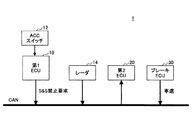
図1は、車両制御装置1の概略構成例を示す図である。車両制御装置1は、車両に搭載される。 FIG. 1 is a diagram illustrating a schematic configuration example of the vehicle control device 1. The vehicle control device 1 is mounted on a vehicle.
車両制御装置1は、第1ECU(Electronic Control Unit)10と、第2ECU20と、ブレーキECU30とを含む。第1ECU10、第2ECU20及びブレーキECU30は、例えばCAN(controller area network)などの適切なバスを介して接続される。
The vehicle control device 1 includes a first ECU (Electronic Control Unit) 10, a
第1ECU10は、先行車追従制御機能を有する。先行車追従制御機能は、ACCに代表されるが、呼び名は任意であり、その類の制御(例えば、CACC(Cooperative Adaptive Cruise Control)等)であればよい。但し、先行車追従制御機能は、好ましくは、車速0以上から作動する機能(例えば、全車速ACC)である。以下では、先行車追従制御機能は、車速0以上から作動するものとして説明を続ける。
The
第1ECU10には、ACCスイッチ12が接続されている。ACCスイッチ12は、車室内(例えばステアリングコラム)に設けられ、ユーザによる操作が可能である。ACCスイッチ12は、オン、オフ、リジューム(復帰)、速度設定(増速、減速等)、キャンセル等を行うことができるスイッチであってよく、マスタースイッチを含んでもよい。
An
第1ECU10には、音波(例えば超音波)や電波(例えばミリ波)、光波(例えばレーザー)等を用いて先行車情報(相対距離、相対速度等)を検出するレーダ14が接続されている。レーダ14は、例えばレーザーレーダ、ミリ波レーダ、超音波レーダ等であってよい。また、レーダ14に代えて又は加えて、画像センサが使用されてもよい。第1ECU10は、レーダ14からの先行車情報等に基づいて、先行車追従制御を行う。先行車追従制御は、例えば、加速制御、減速制御、定速走行制御等を含んでよい。 The first ECU 10 is connected to a radar 14 that detects preceding vehicle information (relative distance, relative speed, etc.) using sound waves (for example, ultrasonic waves), radio waves (for example, millimeter waves), light waves (for example, lasers), or the like. The radar 14 may be, for example, a laser radar, a millimeter wave radar, an ultrasonic radar, or the like. An image sensor may be used instead of or in addition to the radar 14. The first ECU 10 performs preceding vehicle follow-up control based on the preceding vehicle information from the radar 14 and the like. The preceding vehicle following control may include, for example, acceleration control, deceleration control, constant speed traveling control, and the like.
第2ECU20は、エンジンの自動停止機能を有する。エンジンの自動停止機能は、任意であるが、S&S(Stop & Start)又はその類であってよい。エンジンの自動停止機能は、エンジンの再始動を伴うものであってよい。 The second ECU 20 has an automatic engine stop function. The engine automatic stop function is optional, but may be S & S (Stop & Start) or the like. The engine automatic stop function may be accompanied by engine restart.
第2ECU20は、車速情報等に基づいて、所定のS&S開始条件が成立したか否かを判定し、所定のS&S開始条件が成立したと判定した場合に、エンジン自動停止機能を作動させる。エンジン自動停止機能を作動させることは、エンジンを停止させることを含む。S&S開始条件は、車速が所定車速Vth(以下、「E/G停止車速Vth」という)以下であることを含む。E/G停止車速Vthは、0であってもよいし、例えば13km/h程度の低車速領域内の値であってよいし、可変されてもよい。尚、S&S開始条件に含まれるその他の条件は、任意であるが、例えば、バッテリのオープン故障が検出されていないことや、ブレーキペダルが踏まれていることや、ブースタ負圧の大きさが所定値以上であること、その他、空調状態やバッテリ60の充電状態(SOC:State Of Charge)、道路勾配等に関する条件をアンド条件で含んでよい。 The second ECU 20 determines whether or not a predetermined S & S start condition is satisfied based on vehicle speed information and the like, and activates the engine automatic stop function when it is determined that the predetermined S & S start condition is satisfied. Activating the engine automatic stop function includes stopping the engine. The S & S start condition includes that the vehicle speed is equal to or lower than a predetermined vehicle speed Vth (hereinafter referred to as “E / G stop vehicle speed Vth”). The E / G stop vehicle speed Vth may be 0, may be a value within a low vehicle speed range of, for example, about 13 km / h, or may be variable. The other conditions included in the S & S start condition are arbitrary. For example, the battery open failure is not detected, the brake pedal is depressed, and the booster negative pressure is predetermined. In addition, the condition regarding the air conditioning state, the state of charge of the battery 60 (SOC: State Of Charge), the road gradient, and the like may be included as AND conditions.
第2ECU20は、所定のS&S終了条件が成立したか否かを判定し、所定のS&S終了条件が成立したと判定した場合に、エンジン自動停止機能の作動を終了させる。エンジン自動停止機能の作動を終了させることは、エンジンを始動させることを含む。所定のS&S終了条件は、任意であるが、典型的には、例えば、ブレーキペダルの踏み込みが解除されたことや、ブースタ負圧の大きさが所定値未満になったこと、その他、空調状態(空調快適性の低下)やバッテリ状態(充電量の低下)等に関する条件を含んでよい。
The
ブレーキECU30は、ブレーキアクチュエータ(図示せず)を制御する。ブレーキECU30は、車輪速センサ(図示せず)に基づいて算出した車速情報を第1ECU10及び第2ECU20に、例えばCANを介して、供給する。尚、第1ECU10及び/又は第2ECU20は、車速情報を他のECUから取得してもよいし、車輪速センサからの検出信号に基づいて直接的に取得してもよい。また、第1ECU10及び/又は第2ECU20は、車輪速センサからの情報に代えて又は加えて、車速情報を、GPS受信機からの自車位置の変化やトランスミッションの出力シャフトの回転数等から取得してもよい。
The
図2は、第1ECU10により実行されるS&S禁止要求生成処理の一例を示すフローチャートである。図2に示す処理は、車両のイグニッションスイッチがオン状態であり、ACCスイッチ12がオン位置にある間、所定周期毎に繰り返し実行されてもよい。
FIG. 2 is a flowchart showing an example of the S & S prohibition request generation process executed by the
ステップ200では、第1ECU10は、最新の車速情報に基づいて、車速がE/G停止車速Vth以下であるか否かを判定する。車速がE/G停止車速Vth以下である場合は、今回周期の処理は、ステップ202に進み、それ以外の場合は、今回周期の処理はそのまま終了する。
In step 200, the first ECU 10 determines whether or not the vehicle speed is equal to or lower than the E / G stop vehicle speed Vth based on the latest vehicle speed information. If the vehicle speed is equal to or lower than the E / G stop vehicle speed Vth, the current cycle process proceeds to
ステップ202では、第1ECU10は、ACCスイッチ12によりリジューム指令が入力されたか否かを判定する。リジューム指令は、典型的には、ACCの作動による定速走行中に速度セットをブレーキペダルやクラッチペダルを踏んで一旦解除した後、運転者がACCの作動を復帰させたいときに、ACCスイッチ12を例えばリジューム位置に操作することにより入力される。尚、この際、車速は、解除前の設定車速まで緩やかに加速される。ACCスイッチ12によりリジューム指令が入力された場合は、今回周期の処理は、ステップ204に進み、それ以外の場合は、今回周期の処理はそのまま終了する。
In
ステップ204では、第1ECU10は、S&S禁止要求を出力する。S&S禁止要求は、第2ECU20に対してエンジン自動停止機能を作動させないように要求する信号である。尚、第1ECU10は、S&S禁止要求を出力した場合、ある一定数の周期にわたり、ステップ200で肯定判定となる限り、ステップ202の判定を行うことなく、S&S禁止要求を出力してもよい。
In step 204, the
ここで、先行車追従制御機能による加速が必要となった時にエンジン自動停止機能が作動すると、エンジンを再始動する必要があり、無駄が生じる。また、先行車追従制御機能による加速が必要となった時にエンジン自動停止機能に起因してエンジンが既に停止状態であると、直ちにエンジンを始動する必要がある。この点、図2に示す処理によれば、車速がE/G停止車速Vth以下であり、且つ、ACCスイッチ12によりリジューム指令が入力された場合に、S&S禁止要求が出力される。S&S禁止要求が出力されると、基本的に(例外について後述)、第2ECU20によるエンジン自動停止機能が作動しない状態が形成される。従って、図2に示す処理によれば、エンジン自動停止機能に起因してエンジンが停止状態である状況下で先行車追従制御機能による加速が必要となった時に、エンジン自動停止機能の作動を禁止し又は停止状態のエンジンを直ちに始動させることができる。
Here, if the engine automatic stop function is activated when acceleration by the preceding vehicle following control function is required, it is necessary to restart the engine, resulting in waste. In addition, when acceleration by the preceding vehicle following control function is required, if the engine is already stopped due to the automatic engine stop function, it is necessary to start the engine immediately. In this regard, according to the processing shown in FIG. 2, when the vehicle speed is equal to or lower than the E / G stop vehicle speed Vth and a resume command is input by the
尚、図2に示す例では、ステップ200において、第1ECU10は、車速がE/G停止車速Vth以下であるか否かを判定するが、車速が所定車速(≠E/G停止車速Vth)以下であるか否かを判定してもよい。これは、第1ECU10及び第2ECU20間で生じうる車速の読み取り誤差(後述)を考慮するものである。従って、例えば、所定車速は、E/G停止車速Vthに対して所定誤差だけ小さい値であってもよい。所定誤差は、例えば、第1ECU10及び第2ECU20間で生じうる車速の読み取り誤差に応じて決定されてもよい。また、同様の観点から、ステップ202において、第1ECU10は、車速が所定車速以下である状態が所定時間以上継続したか否かを判定してもよい。
In the example shown in FIG. 2, in step 200, the
また、図2に示す例では、第1ECU10は、車速がE/G停止車速Vth以下であり、且つ、ACCスイッチ12によりリジューム指令が入力された場合に、S&S禁止要求を出力するが、これに加えて又は代えて、他の出力条件でS&S禁止要求を出力してもよい。他の出力条件は、エンジン自動停止機能が作動されうる車速領域において先行車追従制御機能による加速制御が予測又は実行される条件であってよく、例えば先行車追従制御機能による目標加速度が所定値以上となることであってもよい。
In the example shown in FIG. 2, the
図3は、第2ECU20により実行されるマスクフラグ設定処理の一例を示すフローチャートである。図3に示す処理は、イグニッションスイッチがオンである間、S&S禁止要求フラグ(後述)が“0”である状態において、S&S禁止要求を受信した場合(ステップ300参照)に起動される割り込み処理であってよい。
FIG. 3 is a flowchart showing an example of a mask flag setting process executed by the
ステップ300では、第2ECU20は、第1ECU10からS&S禁止要求を受信したか否かを判定する。即ち、第2ECU20は、第1ECU10からS&S禁止要求が出力されているか否かを判定する。第1ECU10からS&S禁止要求を受信した場合は、ステップ302に進み、それ以外の場合は、第1ECU10からのS&S禁止要求の出力を待機する状態となる。
In step 300, the
ステップ302では、第2ECU20は、最新の車速情報に基づいて、車速がE/G停止車速Vthより大きいか否かを判定する。車速がE/G停止車速Vthより大きい場合は、マスクフラグ設定処理は、ステップ304に進み、それ以外の場合は、今回受信のS&S禁止要求に対するマスクフラグ設定処理はそのまま終了する。
In step 302, the
ステップ304では、第2ECU20は、マスクフラグを“1”にセットする。マスクフラグは、第1ECU10からのS&S禁止要求をマスクするか否かを定めるフラグであり、“1”はマスクする状態を表し、“0”はマスクしない状態を表す。マスクフラグは、イグニッションスイッチのオフ時又はオン時に“0”にリセットされる。あるトリップ中に一旦マスクフラグが“1”にセットされると、その後、イグニッションスイッチがオフになるまで、“1”にセットされた状態が維持される。
In step 304, the
図3に示す処理によれば、第1ECU10からS&S禁止要求を受信したときに車速がE/G停止車速Vthより大きい場合は、マスクフラグを“1”にセットすることができる。S&S禁止要求は、図2に示したように、車速がE/G停止車速Vth以下である場合にしか出力されない。従って、第1ECU10からS&S禁止要求を受信したときに車速がE/G停止車速Vthより大きいことは、先行車追従制御機能に何らかの異常があることを示唆する。先行車追従制御機能の異常としては、例えば、第1ECU10の暴走等がある。従って、図3に示す処理によれば、先行車追従制御機能の異常時にマスクフラグを“1”にセットすることができる。
According to the process shown in FIG. 3, when the vehicle speed is higher than the E / G stop vehicle speed Vth when the S & S prohibition request is received from the
尚、図3に示す処理では、第1ECU10からS&S禁止要求を受信したときにマスクフラグを“1”にセットするための条件として、そのときの車速がE/G停止車速Vthより大きいことが必要とされる。但し、第1ECU10及び第2ECU20間で生じうる車速の読み取り誤差を考慮するために、ステップ302では、第2ECU20は、車速がE/G停止車速Vthよりも所定値以上(>0)大きいか否かを判定してもよいし、及び/又は、車速がE/G停止車速Vthより大きい状態が所定時間以上継続したか否かを判定してもよい。尚、第1ECU10及び第2ECU20間での車速の読み取り誤差は、CAN上の車速信号の読み取りタイミングの相違に起因して生じ、かかるタイミングの相違は、第1ECU10からS&S禁止要求の出力時点から第2ECU20S&S禁止要求の受信時点までの時間差等に起因して生じうる。
In the process shown in FIG. 3, as a condition for setting the mask flag to “1” when the S & S prohibition request is received from the
また、図3に示す処理では、第1ECU10からS&S禁止要求を受信したときにマスクフラグを“1”にセットするための条件として、そのときの車速がE/G停止車速Vthより大きいことが必要とされる。しかしながら、車速がE/G停止車速Vthより大きいことに代えて又は加えて、他の1つ以上の条件をアンド条件又はオア条件で追加してもよい。このとき、他の条件は、第1ECU10におけるS&S禁止要求の出力条件の裏であってよい。即ち、「出力条件が満たされたならばS&S禁止要求が出力される」という命題に関して対偶が真でないときはマスクフラグを“1”にセットすることとしてよい。
In the process shown in FIG. 3, as a condition for setting the mask flag to “1” when the S & S prohibition request is received from the
図4は、第1ECU10からS&S禁止要求を受信したときのエンジン自動停止機能の作動方法の一例を示すフローチャートである。図4に示す処理は、イグニッションスイッチがオンである間、エンジン自動停止機能の非作動中(エンジン作動中)に、所定周期毎に繰り返し実行されてよい。
FIG. 4 is a flowchart illustrating an example of an operation method of the engine automatic stop function when an S & S prohibition request is received from the
ステップ400では、第2ECU20は、第1ECU10からS&S禁止要求を受信したか否かを判定する。即ち、第2ECU20は、第1ECU10からS&S禁止要求が出力されているか否かを判定する。第1ECU10からS&S禁止要求を受信した場合は、ステップ402に進み、それ以外の場合は、後述する図5の処理に進む。
In
ステップ402では、第2ECU20は、最新の車速情報に基づいて、車速がE/G停止車速Vth以下であるか否かを判定する。車速がE/G停止車速Vth以下である場合は、今回周期の処理は、ステップ404に進み、それ以外の場合は、今回周期の処理は、そのまま終了する。
In step 402, the
ステップ404では、第2ECU20は、マスクフラグが“1”であるか否かを判定する。マスクフラグが“1”である場合は、ステップ406に進み、マスクフラグが“1”でない場合(即ち、マスクフラグが“0”である場合)は、今回周期の処理は、そのまま終了する。
In step 404, the
ステップ406では、第2ECU20は、他のS&S開始条件が成立することを条件として、エンジン自動停止機能を作動させる。他のS&S開始条件が成立しない場合は、今回周期の処理は、そのまま終了する。尚、他のS&S開始条件が成立するか否かは、ステップ402で判定されてもよいし、逆に、ステップ402の条件は、他のS&S開始条件としてステップ406で判定されてもよい。エンジン自動停止機能が作動されることでエンジン停止状態が形成されると、後述の図6の処理が開始される。
In
図4に示す処理によれば、第2ECU20は、第1ECU10からS&S禁止要求を受信したときにマスクフラグが“0”である場合は、ステップ406に進まず、エンジン自動停止機能を作動させない。これにより、先行車追従制御機能の異常がない時は、第1ECU10からのS&S禁止要求に応じてエンジン自動停止機能が禁止される。他方、第2ECU20は、第1ECU10からS&S禁止要求を受信したときにマスクフラグが“1”である場合は、ステップ406に進み、他のS&S開始条件が成立することを条件としてエンジン自動停止機能を作動させる。これにより、先行車追従制御機能の異常時は、第1ECU10からのS&S禁止要求をマスクしてエンジン自動停止機能の作動させることができる。
According to the processing shown in FIG. 4, if the mask flag is “0” when the S & S prohibition request is received from the
ところで、第1ECU10は、自身で先行車追従制御機能の異常を検出する自己異常検出機能を有する場合、自身で先行車追従制御機能の異常を検出した場合に、先行車追従制御機能を停止して、S&S禁止要求を出力しないようにすることができる。しかしながら、かかる自己異常検出機能によって検出できないような異常(例えば第1ECU10の暴走等)が発生した場合、S&S禁止要求が不必要に出力される虞がある。これは、第1ECU10が自己異常検出機能を備えていない場合も同じである。かかる場合には、不必要なS&S禁止要求によってエンジン自動停止機能の作動機会が低減され、エンジン自動停止機能による効果(燃費やエミッション低減)を十分に発揮できない虞がある。
By the way, when the
これに対して、図4に示す処理によれば、上述の如く、先行車追従制御機能の異常時は、第2ECU20側で第1ECU10からのS&S禁止要求をマスクしてエンジン自動停止機能の作動可能な状態を継続できる。これにより、先行車追従制御機能の異常時におけるS&S禁止要求の出力に起因した不都合を低減し、エンジン自動停止機能による効果(燃費やエミッション低減)を維持することができる。
On the other hand, according to the process shown in FIG. 4, when the preceding vehicle following control function is abnormal as described above, the engine automatic stop function can be activated by masking the S & S prohibition request from the
図5は、第1ECU10からS&S禁止要求を受信していないときのエンジン自動停止機能の作動方法の一例を示すフローチャートである。
FIG. 5 is a flowchart showing an example of an operation method of the engine automatic stop function when the S & S prohibition request is not received from the
ステップ500では、第2ECU20は、最新の車速情報に基づいて、車速がE/G停止車速Vth以下であるか否かを判定する。車速がE/G停止車速Vth以下である場合は、今回周期の処理は、ステップ502に進み、それ以外の場合は、次回周期から図4の処理を開始する。
In
ステップ502では、第2ECU20は、他のS&S開始条件が成立することを条件として、エンジン自動停止機能を作動させる。尚、他のS&S開始条件が成立しない場合は、今回周期の処理は、そのまま終了し、次回周期から図4の処理を開始する。他のS&S開始条件が成立するか否かは、ステップ500で判定されてもよいし、逆に、ステップ500の条件は、他のS&S開始条件としてステップ502で判定されてもよい。エンジン自動停止機能が作動されることでエンジン停止状態が形成されると、後述の図6の処理が開始される。
In
尚、上述では、説明の都合上、図4及び図5に示す処理を別々に説明したが、これらの処理は統合されてもよい。 In the above description, the processes shown in FIGS. 4 and 5 have been described separately for convenience of explanation. However, these processes may be integrated.
図6は、エンジン自動停止機能の作動中に第1ECU10からS&S禁止要求を受信した場合のエンジン自動停止機能の作動方法の一例を示すフローチャートである。図6に示す処理は、イグニッションスイッチがオンである間、エンジン自動停止機能の作動中(エンジン停止中)に、所定周期毎に繰り返し実行されてよい。
FIG. 6 is a flowchart showing an example of an operation method of the engine automatic stop function when an S & S prohibition request is received from the
ステップ600乃至ステップ604の各処理は、図4に示したステップ400乃至ステップ404の各処理と同様であってよい。ただし、ステップ604において、マスクフラグが“0”である場合は、ステップ606に進み、マスクフラグが“1”である場合は、今回周期の処理は、そのまま終了する。
The processes in
ステップ606では、第2ECU20は、エンジン自動停止機能の作動を終了する。ステップ606の処理が終了すると、次回周期から図4の処理を開始する。
In
図6に示す処理によれば、第2ECU20は、第1ECU10からS&S禁止要求を受信したときにマスクフラグが“0”である場合は、ステップ606に進み、エンジン自動停止機能の作動を終了する。これにより、先行車追従制御機能の異常がない時は、第1ECU10からのS&S禁止要求に応じてエンジンを速やかに再始動することができる。他方、第2ECU20は、第1ECU10からS&S禁止要求を受信したときにマスクフラグが“1”である場合は、ステップ606に進まず、エンジン自動停止機能の作動を終了させない。これにより、先行車追従制御機能の異常時は、第1ECU10からのS&S禁止要求をマスクしてエンジン自動停止機能の作動状態を維持することができる。
According to the process shown in FIG. 6, if the mask flag is “0” when the
図7は、エンジン自動停止機能の作動中に第1ECU10からS&S禁止要求を受信していない場合のエンジン自動停止機能の作動方法の一例を示すフローチャートである。
FIG. 7 is a flowchart showing an example of the operation method of the engine automatic stop function when the S & S prohibition request is not received from the
ステップ700の処理は、図5に示したステップ500の処理と同様であってよい。但し、車速がE/G停止車速Vth以下である場合は、今回周期の処理は、ステップ702に進み、それ以外の場合は、次回周期から図6の処理を開始する。
The process of step 700 may be the same as the process of
ステップ702では、第2ECU20は、所定のS&S終了条件が成立することを条件として、エンジン自動停止機能の作動を終了する。尚、所定のS&S終了条件が成立しない場合は、今回周期の処理は、そのまま終了し、次回周期から図6の処理を開始する。所定のS&S終了条件は、上述の通りであってよい。エンジン自動停止機能の作動を終了した場合は、次回周期から図4の処理を開始する。
In
尚、上述では、説明の都合上、図6及び図7に示す処理を別々に説明したが、これらの処理は統合されてもよい。 In the above description, the processes shown in FIGS. 6 and 7 have been described separately for convenience of explanation. However, these processes may be integrated.
以上、各実施例について詳述したが、特定の実施例に限定されるものではなく、特許請求の範囲に記載された範囲内において、種々の変形及び変更が可能である。また、前述した実施例の構成要素を全部又は複数を組み合わせることも可能である。 Although each embodiment has been described in detail above, it is not limited to a specific embodiment, and various modifications and changes can be made within the scope described in the claims. It is also possible to combine all or a plurality of the components of the above-described embodiments.
例えば、上述した実施例では、マスクフラグは1トリップ毎にリセットされているが、マスクフラグのリセットタイミングは任意である。例えば、マスクフラグは、複数トリップ毎にリセットされてもよいし、所定時間経過毎に又は所定距離走行毎にリセットされてもよいし、所定のリセット入力があった場合にリセットされてもよい。 For example, in the embodiment described above, the mask flag is reset every trip, but the reset timing of the mask flag is arbitrary. For example, the mask flag may be reset every multiple trips, may be reset every time a predetermined time elapses or every predetermined distance, or may be reset when a predetermined reset input is received.
1 車両制御装置
10 第1ECU
12 ACCスイッチ
20 第2ECU
1
12
Claims (2)
エンジンの自動停止機能を有する第2制御装置であって、車速が前記所定車速よりも大きい状況下で前記禁止要求が出力された場合に、制御フラグを前記先行車追従制御機能の異常を示す状態に設定する第2制御装置とを含み、
前記第2制御装置は、前記制御フラグが前記先行車追従制御機能の異常を示す状態においては、前記第1制御装置から出力された前記禁止要求に反してエンジンの自動停止機能を維持する、車両制御装置。 A first vehicle follow-up control function for controlling the vehicle speed based on the traveling state of the preceding vehicle, and outputting a prohibition request for the automatic engine stop function when the acceleration control is performed in a situation where the vehicle speed is equal to or lower than a predetermined vehicle speed . A control device;
A second control device having an automatic engine stop function , wherein the control flag indicates an abnormality of the preceding vehicle following control function when the prohibition request is output under a situation where the vehicle speed is greater than the predetermined vehicle speed. A second control device set to
It said second control device, in a state in which the control flag indicates abnormality in the adaptive cruise control function, you keep the automatic stop function of the engine against the prohibition request output from said first control device, Vehicle control device.
Priority Applications (4)
| Application Number | Priority Date | Filing Date | Title |
|---|---|---|---|
| JP2014120997A JP6326993B2 (en) | 2014-06-11 | 2014-06-11 | Vehicle control device |
| US15/305,255 US10030599B2 (en) | 2014-06-11 | 2015-05-22 | Vehicle control apparatus |
| PCT/JP2015/065491 WO2015190309A1 (en) | 2014-06-11 | 2015-05-22 | Vehicle control apparatus |
| CN201580030729.6A CN106660555B (en) | 2014-06-11 | 2015-05-22 | Controller of vehicle |
Applications Claiming Priority (1)
| Application Number | Priority Date | Filing Date | Title |
|---|---|---|---|
| JP2014120997A JP6326993B2 (en) | 2014-06-11 | 2014-06-11 | Vehicle control device |
Publications (3)
| Publication Number | Publication Date |
|---|---|
| JP2016000976A JP2016000976A (en) | 2016-01-07 |
| JP2016000976A5 JP2016000976A5 (en) | 2017-04-13 |
| JP6326993B2 true JP6326993B2 (en) | 2018-05-23 |
Family
ID=53398169
Family Applications (1)
| Application Number | Title | Priority Date | Filing Date |
|---|---|---|---|
| JP2014120997A Active JP6326993B2 (en) | 2014-06-11 | 2014-06-11 | Vehicle control device |
Country Status (4)
| Country | Link |
|---|---|
| US (1) | US10030599B2 (en) |
| JP (1) | JP6326993B2 (en) |
| CN (1) | CN106660555B (en) |
| WO (1) | WO2015190309A1 (en) |
Families Citing this family (4)
| Publication number | Priority date | Publication date | Assignee | Title |
|---|---|---|---|---|
| JP2019015278A (en) * | 2017-07-11 | 2019-01-31 | トヨタ自動車株式会社 | Control device of vehicle |
| JP6978377B2 (en) * | 2018-05-10 | 2021-12-08 | 本田技研工業株式会社 | Vehicle control device and vehicle equipped with vehicle control device |
| JP7255113B2 (en) | 2018-09-13 | 2023-04-11 | いすゞ自動車株式会社 | Vehicle control device and vehicle control method |
| CN112360658B (en) * | 2020-09-25 | 2022-04-26 | 东风小康汽车有限公司重庆分公司 | Engine start-stop control method compatible with ACC system |
Family Cites Families (19)
| Publication number | Priority date | Publication date | Assignee | Title |
|---|---|---|---|---|
| JP3323039B2 (en) * | 1995-08-17 | 2002-09-09 | 日野自動車株式会社 | Automotive power converter |
| JP3468167B2 (en) * | 1999-08-25 | 2003-11-17 | トヨタ自動車株式会社 | Abnormality detection device for power supply circuit and automatic stop / start control device for internal combustion engine |
| WO2004038260A1 (en) * | 2002-10-28 | 2004-05-06 | Nissan Diesel Motor Co., Ltd. | Automatic gear shift controller |
| FR2875557B1 (en) * | 2004-09-23 | 2006-11-24 | Valeo Equip Electr Moteur | METHOD FOR CONTROLLING A ROTATING ELECTRIC MACHINE |
| JP2006183600A (en) | 2004-12-28 | 2006-07-13 | Toyota Motor Corp | Device and method for control of engine stop and restart, and vehicle carrying the device thereon |
| JP2006290328A (en) * | 2005-03-16 | 2006-10-26 | Nissan Motor Co Ltd | Preceding vehicle follow-up control unit |
| JP4674491B2 (en) * | 2005-05-20 | 2011-04-20 | 日産自動車株式会社 | Preceding vehicle tracking control device |
| DE102006009654A1 (en) * | 2006-03-02 | 2007-11-08 | Robert Bosch Gmbh | Device for switching on and off a vehicle engine depending on the traffic situation |
| US7831364B2 (en) * | 2006-08-11 | 2010-11-09 | Clark Equipment Company | “Off-board” control for a power machine or vehicle |
| JP2008309068A (en) * | 2007-06-14 | 2008-12-25 | Toyota Motor Corp | Vehicle controller |
| JP4803222B2 (en) * | 2008-08-21 | 2011-10-26 | マツダ株式会社 | Vehicle system control method and vehicle system |
| US8825345B2 (en) * | 2010-07-16 | 2014-09-02 | Honda Motor Co., Ltd. | Engine control for a motor vehicle |
| JP2012111412A (en) * | 2010-11-26 | 2012-06-14 | Fuji Heavy Ind Ltd | Vehicle control system |
| US20120191317A1 (en) * | 2011-01-24 | 2012-07-26 | Armin Mueller-Lerwe | Method and Device for Controlling the Operation of an Internal Combustion Engine |
| JP2012206593A (en) * | 2011-03-29 | 2012-10-25 | Fuji Heavy Ind Ltd | Cruise control system |
| JP5867353B2 (en) * | 2012-09-28 | 2016-02-24 | トヨタ自動車株式会社 | Vehicle control device |
| JP5594343B2 (en) * | 2012-10-02 | 2014-09-24 | トヨタ自動車株式会社 | Control device, vehicle, and control method |
| JP5673644B2 (en) * | 2012-10-11 | 2015-02-18 | トヨタ自動車株式会社 | Hybrid vehicle |
| JP6082638B2 (en) * | 2013-03-29 | 2017-02-15 | 日立オートモティブシステムズ株式会社 | Travel control device and travel control system |
-
2014
- 2014-06-11 JP JP2014120997A patent/JP6326993B2/en active Active
-
2015
- 2015-05-22 CN CN201580030729.6A patent/CN106660555B/en active Active
- 2015-05-22 US US15/305,255 patent/US10030599B2/en active Active
- 2015-05-22 WO PCT/JP2015/065491 patent/WO2015190309A1/en active Application Filing
Also Published As
| Publication number | Publication date |
|---|---|
| CN106660555B (en) | 2019-02-12 |
| US10030599B2 (en) | 2018-07-24 |
| WO2015190309A1 (en) | 2015-12-17 |
| US20170107926A1 (en) | 2017-04-20 |
| JP2016000976A (en) | 2016-01-07 |
| CN106660555A (en) | 2017-05-10 |
Similar Documents
| Publication | Publication Date | Title |
|---|---|---|
| JP5715454B2 (en) | Vehicle driving support device | |
| EP3318460B1 (en) | Control apparatus for vehicle | |
| JP5206868B2 (en) | Driving assistance device | |
| WO2008059347A2 (en) | Vehicle control device and control method therefor | |
| JP2013129228A (en) | Vehicle control device | |
| JP2006321268A (en) | Economic running control method and economic running controlling device | |
| JP2015101207A (en) | Vehicular control apparatus and engine control method | |
| JP6326993B2 (en) | Vehicle control device | |
| US11104339B2 (en) | Driving support system | |
| US9278680B2 (en) | Control device and control method for vehicle | |
| JP2005255146A (en) | Vehicle decelerating control device | |
| JP6668640B2 (en) | Driving support device and driving support method | |
| JP2013136288A (en) | Collision damage reducing system | |
| JP6312356B2 (en) | Vehicle control device | |
| WO2015093189A1 (en) | Vehicle control device | |
| JP2019196746A (en) | Vehicle control device, and vehicle with vehicle control device | |
| JP2016070241A (en) | Control device for vehicle | |
| JP2016000977A (en) | Vehicle control device | |
| JP6406927B2 (en) | Vehicle control device | |
| JP2016070242A (en) | Control device for vehicle | |
| JP6241122B2 (en) | Vehicle control device | |
| KR20140085886A (en) | Integration Interworking Control Method and System | |
| JP7381545B2 (en) | Vehicle control device, vehicle control method, and program | |
| JP2013234674A (en) | Collision damage reducing system | |
| JP7268464B2 (en) | vehicle controller |
Legal Events
| Date | Code | Title | Description |
|---|---|---|---|
| A521 | Request for written amendment filed |
Free format text: JAPANESE INTERMEDIATE CODE: A523 Effective date: 20170309 |
|
| A621 | Written request for application examination |
Free format text: JAPANESE INTERMEDIATE CODE: A621 Effective date: 20170309 |
|
| A131 | Notification of reasons for refusal |
Free format text: JAPANESE INTERMEDIATE CODE: A131 Effective date: 20171024 |
|
| TRDD | Decision of grant or rejection written | ||
| A01 | Written decision to grant a patent or to grant a registration (utility model) |
Free format text: JAPANESE INTERMEDIATE CODE: A01 Effective date: 20180320 |
|
| A61 | First payment of annual fees (during grant procedure) |
Free format text: JAPANESE INTERMEDIATE CODE: A61 Effective date: 20180402 |
|
| R151 | Written notification of patent or utility model registration |
Ref document number: 6326993 Country of ref document: JP Free format text: JAPANESE INTERMEDIATE CODE: R151 |