JP6324316B2 - Air conditioner indoor unit - Google Patents
Air conditioner indoor unit Download PDFInfo
- Publication number
- JP6324316B2 JP6324316B2 JP2014544449A JP2014544449A JP6324316B2 JP 6324316 B2 JP6324316 B2 JP 6324316B2 JP 2014544449 A JP2014544449 A JP 2014544449A JP 2014544449 A JP2014544449 A JP 2014544449A JP 6324316 B2 JP6324316 B2 JP 6324316B2
- Authority
- JP
- Japan
- Prior art keywords
- wind direction
- air
- vane
- direction vane
- air conditioner
- Prior art date
- Legal status (The legal status is an assumption and is not a legal conclusion. Google has not performed a legal analysis and makes no representation as to the accuracy of the status listed.)
- Expired - Fee Related
Links
Images
Classifications
-
- F—MECHANICAL ENGINEERING; LIGHTING; HEATING; WEAPONS; BLASTING
- F24—HEATING; RANGES; VENTILATING
- F24F—AIR-CONDITIONING; AIR-HUMIDIFICATION; VENTILATION; USE OF AIR CURRENTS FOR SCREENING
- F24F13/00—Details common to, or for air-conditioning, air-humidification, ventilation or use of air currents for screening
- F24F13/08—Air-flow control members, e.g. louvres, grilles, flaps or guide plates
-
- F—MECHANICAL ENGINEERING; LIGHTING; HEATING; WEAPONS; BLASTING
- F24—HEATING; RANGES; VENTILATING
- F24F—AIR-CONDITIONING; AIR-HUMIDIFICATION; VENTILATION; USE OF AIR CURRENTS FOR SCREENING
- F24F1/00—Room units for air-conditioning, e.g. separate or self-contained units or units receiving primary air from a central station
- F24F1/0007—Indoor units, e.g. fan coil units
- F24F1/0011—Indoor units, e.g. fan coil units characterised by air outlets
-
- F—MECHANICAL ENGINEERING; LIGHTING; HEATING; WEAPONS; BLASTING
- F24—HEATING; RANGES; VENTILATING
- F24F—AIR-CONDITIONING; AIR-HUMIDIFICATION; VENTILATION; USE OF AIR CURRENTS FOR SCREENING
- F24F1/00—Room units for air-conditioning, e.g. separate or self-contained units or units receiving primary air from a central station
- F24F1/0007—Indoor units, e.g. fan coil units
- F24F1/0043—Indoor units, e.g. fan coil units characterised by mounting arrangements
- F24F1/0047—Indoor units, e.g. fan coil units characterised by mounting arrangements mounted in the ceiling or at the ceiling
-
- F—MECHANICAL ENGINEERING; LIGHTING; HEATING; WEAPONS; BLASTING
- F24—HEATING; RANGES; VENTILATING
- F24F—AIR-CONDITIONING; AIR-HUMIDIFICATION; VENTILATION; USE OF AIR CURRENTS FOR SCREENING
- F24F13/00—Details common to, or for air-conditioning, air-humidification, ventilation or use of air currents for screening
- F24F13/08—Air-flow control members, e.g. louvres, grilles, flaps or guide plates
- F24F13/10—Air-flow control members, e.g. louvres, grilles, flaps or guide plates movable, e.g. dampers
- F24F13/14—Air-flow control members, e.g. louvres, grilles, flaps or guide plates movable, e.g. dampers built up of tilting members, e.g. louvre
-
- F—MECHANICAL ENGINEERING; LIGHTING; HEATING; WEAPONS; BLASTING
- F24—HEATING; RANGES; VENTILATING
- F24F—AIR-CONDITIONING; AIR-HUMIDIFICATION; VENTILATION; USE OF AIR CURRENTS FOR SCREENING
- F24F5/00—Air-conditioning systems or apparatus not covered by F24F1/00 or F24F3/00, e.g. using solar heat or combined with household units such as an oven or water heater
- F24F5/0007—Air-conditioning systems or apparatus not covered by F24F1/00 or F24F3/00, e.g. using solar heat or combined with household units such as an oven or water heater cooling apparatus specially adapted for use in air-conditioning
Landscapes
- Engineering & Computer Science (AREA)
- Chemical & Material Sciences (AREA)
- Combustion & Propulsion (AREA)
- Mechanical Engineering (AREA)
- General Engineering & Computer Science (AREA)
- Life Sciences & Earth Sciences (AREA)
- Sustainable Development (AREA)
- Air-Flow Control Members (AREA)
Description
本発明は、空気調和機に関するものである。 The present invention relates to an air conditioner.
従来の天井埋込型の空気調和機としては、例えば、特許文献1に開示されたものがある。この空気調和機においては、本体吹出口それぞれの風向ベーンに屈曲部が設けられており、この屈曲部は、風向ベーンの上流側部分に位置し、吹出口それぞれの本体中央側の風路壁から離れる方向に屈曲されている。このような屈曲部を設けることによって、風向ベーンの本体中央側(内側)の風路面積を確保することができ、それにより、この部分の風速が低下せず、室内空気を巻き込みにくくなる。そのため、冷房運転時に温度の高い室内空気と温度の低い吹出し空気との混合による吹出口の結露を防止することが期待できる。 As a conventional ceiling-embedded air conditioner, for example, there is one disclosed in Patent Document 1. In this air conditioner, a bent portion is provided in the wind direction vane of each main body outlet, and this bent portion is located on the upstream side portion of the wind direction vane and extends from the air channel wall on the center side of each main body of the outlet. It is bent away. By providing such a bent portion, it is possible to secure the air passage area on the center side (inside) of the main body of the wind direction vane, and thereby the wind speed of this portion does not decrease, and it becomes difficult to entrain indoor air. Therefore, it can be expected to prevent dew condensation at the outlet due to mixing of high temperature indoor air and low temperature blowing air during cooling operation.
しかしながら、上述した特許文献1に開示の空気調和機では、風向ベーンの内側への流入風量を増加させることができるが、風向ベーンの吹出方向を水平方向に近づけるような態様では、気流の剥離が生じる恐れがある。 However, in the air conditioner disclosed in Patent Document 1 described above, it is possible to increase the amount of air flowing into the inside of the wind direction vane. However, in an aspect in which the blowing direction of the wind direction vane is close to the horizontal direction, separation of the air flow is performed. May occur.
本発明は、上記課題を解決するためになされたもので、吹出口付近での室内空気の巻き込みによる結露は防止しつつ、風向ベーンにおける気流の剥離も防止することができる、空気調和機を提供することを目的とする。 The present invention has been made in order to solve the above-described problem, and provides an air conditioner that can prevent dew condensation due to entrainment of room air in the vicinity of the air outlet and can also prevent separation of airflow in the wind direction vane. The purpose is to do.
上述した目的を達成するため、本発明の空気調和機は、本体内に収容され、且つ、吸込口から本体内に吸込まれ吹出口から対象空間へと吹出される空気の流動路中に配置された熱交換器と、前記吹出口に配置された風向ベーンとを備え、前記風向ベーンは、第1湾曲部と、第2湾曲部とを含み、前記第1湾曲部は、前記第2湾曲部よりも上流側に位置しており、該第1湾曲部の曲率は、該第2湾曲部の曲率よりも大きい。
前記第1湾曲部と前記第2湾曲部との境界部は、水平吹き状態にある前記風向ベーン上における前記吹出口の内側風路壁と最も接近した部分である最接近部に一致するか、または、当該最接近部よりも下流に位置するようにしてもよい。
前記第1湾曲部と前記第2湾曲部とが滑らかにつながっているように構成してもよい。
前記風向ベーンの上流端は、ラウンド形状に形成されており、前記風向ベーンの肉厚は、前記上流端において最大肉厚となるようにしてもよい。
前記風向ベーンの肉厚は、下流端において最小肉厚となるようにしてもよい。
前記風向ベーンは、平板部を更に含み、前記平板部は、前記第1湾曲部の上流側に位置しているようにしてもよい。
前記風向ベーンは、流出角が20°〜40°であり、且つ、流入角が10°〜25°であるように構成されていてもよい。
流出角が20°〜40°で配置された前記風向ベーン及び前記吹出口の内側風路壁で構成される内側風路と、該風向ベーン及び前記吹出口の外側風路壁で構成される外側風路とが、共に、縮小形状となるように構成されていてもよい。
前記風向ベーンにおける前記第1湾曲部と前記第2湾曲部との境界部は、長手方向にわたって下流端や上流端に対する位置が変化しているように構成してもよい。In order to achieve the above-described object, the air conditioner of the present invention is accommodated in the main body, and is disposed in a flow path of air that is sucked into the main body from the suction port and blown out from the outlet to the target space. A heat exchanger and a wind direction vane disposed at the air outlet, the wind direction vane including a first curved portion and a second curved portion, wherein the first curved portion is the second curved portion. The curvature of the first bending portion is larger than the curvature of the second bending portion.
Does the boundary between the first curved part and the second curved part coincide with the closest part which is the part closest to the inner air passage wall of the outlet on the wind direction vane in a horizontal blowing state, Alternatively, it may be positioned downstream of the closest part.
You may comprise so that the said 1st bending part and the said 2nd bending part may be connected smoothly.
The upstream end of the wind direction vane may be formed in a round shape, and the thickness of the wind direction vane may be the maximum thickness at the upstream end.
The thickness of the wind direction vane may be a minimum thickness at the downstream end.
The wind direction vane may further include a flat plate portion, and the flat plate portion may be located upstream of the first curved portion.
The said wind direction vane may be comprised so that an outflow angle may be 20 degrees-40 degrees, and an inflow angle may be 10 degrees-25 degrees.
An inner air passage composed of the wind direction vane and the inner air passage wall of the air outlet arranged at an outflow angle of 20 ° to 40 °, and an outer side constituted of the air direction vane and the outer air passage wall of the air outlet. Both the air paths may be configured to have a reduced shape.
You may comprise the boundary part of the said 1st curved part and the said 2nd curved part in the said wind direction vane so that the position with respect to a downstream end or an upstream end may change over the longitudinal direction.
本発明によれば、吹出口付近での室内空気の巻き込みによる結露は防止しつつ、風向ベーンにおける気流の剥離も防止することができる。 According to the present invention, it is possible to prevent the separation of the air flow in the wind direction vane while preventing the condensation due to the entrainment of the room air in the vicinity of the air outlet.
以下、本発明に係る空気調和機の実施の形態について添付図面に基づいて説明する。なお、図中、同一符号は同一又は対応部分を示すものとする。 Embodiments of an air conditioner according to the present invention will be described below with reference to the accompanying drawings. In the drawings, the same reference numerals indicate the same or corresponding parts.
実施の形態1.
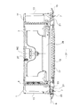
図1は、本発明の実施の形態1に係る空気調和機の内部構造を側方から示す模式図である。より詳細には、本実施の形態1に係る空気調和機は、いわゆるパッケージエアコンの室内機であり、図1は、空気調和機本体の主要部が部屋の天井に埋め込まれ、本体下部が部屋の室内に面した状態を示している。Embodiment 1 FIG.
FIG. 1 is a schematic diagram showing the internal structure of the air conditioner according to Embodiment 1 of the present invention from the side. More specifically, the air conditioner according to Embodiment 1 is a so-called indoor unit of a packaged air conditioner. In FIG. 1, the main part of the air conditioner main body is embedded in the ceiling of the room, and the lower part of the main body is the room air conditioner. It shows the state facing the room.
天井埋込型の空気調和機は、本体1と、ターボファン3と、熱交換器5と、少なくとも一つの風向ベーン7とを備えている。本体1は、対象空間である部屋の天井面9の裏側(部屋と逆側)に埋め込まれている。
The ceiling-embedded air conditioner includes a main body 1, a
一例であるが、本実施の形態1では、本体1は、平面視矩形の本体天板11と、本体天板11の四辺から下方に延びる四面の本体側板13とを有している。換言すると、本体1は、四つの本体側板13からなる角筒体の上端面が本体天板11によって閉塞された箱体である。
As an example, in the first embodiment, the main body 1 has a main
本体1の下部には、すなわち、上記の箱体でいう開放された下端面には、化粧パネル15が、本体1に対して着脱自在に取り付けられている。図1に示されるように、本体天板11は天井面9よりも上方に位置し、化粧パネル15は天井面9とほぼ同一面に位置している。
A
化粧パネル15の中央付近には、本体1への空気の吸込口である吸込グリル17が設けられている。吸込グリル17には、吸込グリル17を通過した後の空気を除塵するフィルタ19が設けられている。
In the vicinity of the center of the
一例であるが、本実施の形態1では、化粧パネル15及び吸込グリル17はそれぞれ平面視矩形の外縁を有している。
As an example, in the first embodiment, the
化粧パネル15の外縁と、吸込グリル17の外縁との間の領域には、空気の吹出口である複数のパネル吹出口21が設けられている。本実施の形態1では、化粧パネル15及び吸込グリル17それぞれが、四辺の外縁を有していることに対応し、パネル吹出口21は、四つ設けられており、パネル吹出口21それぞれが、化粧パネル15及び吸込グリル17における対応する辺に沿うように配置されている。また、四つのパネル吹出口21は、吸込グリル17を包囲するように位置している。
In a region between the outer edge of the
パネル吹出口21それぞれにおける本体1中央側(後述する回転軸RC側)は、内側風路壁23で画定されており、パネル吹出口21それぞれにおける化粧パネル15の外縁側は、外側風路壁25で画定されている。パネル吹出口21のそれぞれには、吹出す空気の方向を調整する風向ベーン7が設けられている。
The center side (the rotation axis RC side to be described later) of each of the
本体1内の中央部には、ファンモータ27が配置されている。ファンモータ27は、本体天板11の下面(本体1の内部空間側)に支持されている。ファンモータ27における下向きに延びる回転軸には、ターボファン3が取り付けられている。さらに、ターボファン3と吸込グリル17との間には、吸込グリル17からターボファン3に向かう吸込風路を形成するベルマウス29が設けられている。ターボファン3は、吸込グリル17から本体1内に空気を吸込み、その空気をパネル吹出口21から対象空間である室内31へと流出させる。
A fan motor 27 is disposed at the center in the main body 1. The fan motor 27 is supported on the lower surface (the inner space side of the main body 1) of the main
ターボファン3における径方向外側には、熱交換器5が配置されている。換言するならば、熱交換器5は、ターボファン3によって本体1内に生じる空気の流動路中に配置されて、その空気と冷媒との間で熱交換を行う。
A
熱交換器5は、水平方向に所定の間隔をあけて配置された複数のフィンと、それらフィンを貫通する伝熱管とを有し、伝熱管は、図示しない周知の室外機に接続配管によって接続されており、それにより熱交換器5には、冷却された冷媒または加熱された冷媒が供給される。なお、ターボファン3、ベルマウス29、熱交換器5の構成や態様は特に限定されるものではなく、本実施の形態1では周知のものが用いられている。
The
このような構成において、ターボファン3が回転すると室内31の空気が化粧パネル15の吸込グリル17に吸い込まれる。そして、フィルタ19において除塵された空気は、本体吸込口を構成するベルマウス29によって案内されてターボファン3に吸い込まれる。さらに、ターボファン3では、下方から上方に向かって吸い込まれた空気が、水平方向に、且つ、径方向でいう外側方向に、吹き出される。そのように吹き出された空気は、熱交換器3を通過する際に、熱交換及び/又は湿度調整された後、流れ方向を下方に変更して、パネル吹出口21それぞれから室内31に吹き出される。このとき、パネル吹出口9それぞれにおいて風向ベーン10によって後述する気流の流出角が制御される。
In such a configuration, when the
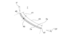
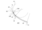
次に、風向ベーンの詳細について図2及び図3も参照して説明する。図2は、本実施の形態1に関する、風向ベーンの長手方向に垂直な断面図であり、図3は、本実施の形態1に関し、風向ベーンの湾曲態様を説明する図である。 Next, the detail of a wind direction vane is demonstrated with reference also to FIG.2 and FIG.3. FIG. 2 is a cross-sectional view perpendicular to the longitudinal direction of the wind direction vane relating to the first embodiment, and FIG. 3 is a diagram illustrating a curved aspect of the wind direction vane relating to the first embodiment.
風向ベーン7は、板状を成しており、その表面及び裏面は共に、湾曲している。図2に示されるように、風向ベーン7の表面側は凸面7aをなしており、風向ベーン7の裏面側は凹面7bをなしている。また、風向ベーン7の凹凸とパネル吹出口21との関係としては、凸面7aが内側風路壁23と対面し、凹面7bが外側風路壁25と対面するような向きで風向ベーン7は配置されている。
The
また、風向ベーン7は、第1湾曲部41と、第2湾曲部43とを含んでいる。一例であるが、本実施の形態1では、風向ベーン7は、第1湾曲部41及び第2湾曲部43のみで構成されている。風向ベーン7における第1湾曲部41は第2湾曲部43よりも上流側に位置している。さらに、第1湾曲部41の曲率は、第2湾曲部43の曲率よりも大きく設定されている。すなわち、第1湾曲部41は、図2及び図3の断面においてみて、第1円FCに沿って弧状に湾曲し、第2湾曲部43は、同断面においてみて、第2円SCに沿って弧状に湾曲しており、第1円FCの半径(曲率半径)が第2円SCの半径(曲率半径)よりも小さく設定されている。
The
また、風向ベーン7の第1湾曲部41と第2湾曲部43との境界部45においては、第1湾曲部41の表裏面と、第2湾曲部43の表裏面とが滑らかにつながっている。換言すると、図3に示されるように、第1円FCと第2円SCとは境界部(変曲点部)45において接している。また、一例であるが、本実施の形態1では、境界部45は、風向ベーン7において下流端47よりも上流端49に近い位置に設定されている。
Moreover, in the
なお、風向ベーン7の上流端49近傍における気流の流入角IFは、上流端49における第1円FCの接線方向に対する流入気流のなす角を示し、風向ベーン7の下流端47近傍における流出気流の流出角OFは、水平方向に対する流出気流のなす角を示すものとする。流入角IFは、図2においてみて、上流端49における第1円FCの接線から時計回りを正の値の角度とし、流出角OFは、図2においてみて、水平方向から時計回りを正の値の角度とする(流入角IF及び流出角OFとも、後述する図6においても同様)。また、流出角OFの範囲が50°〜70°である吹出態様を「下吹き」と称し、流出角OFの範囲が20°〜40°である吹出態様を「水平吹き」と称する。
The inflow angle IF of the airflow in the vicinity of the
このように構成された本実施の形態1に係る空気調和機においては、まず、風向ベーン7の上流側の部分に、上流端49が内側風路壁23から離れる向きに湾曲した第1湾曲部41が含まれているので、風向ベーン7の内側への流入風量を増加させることができ、例えば冷房運転時の室内空気の巻き込みによる結露を防止することができる。さらに加えて、風向ベーン7が第1湾曲部41及び第2湾曲部43を含み且つその第1湾曲部41が第2湾曲部43の曲率よりも大きいので、風向ベーン7を水平吹き角度に設置した場合でも、風向ベーン7に対する気流の流入角IFを極めて小さくすることができ、従来であれば風向ベーンの凸面側で発生していた気流の剥離を防止することができる。このように本実施の形態1によれば、室内空気の巻き込みによる結露を防止しつつ、尚且つ、気流の剥離による圧力損失を低減し、省エネ性能の改善、送風音の低減を図ることも可能となっている。さらに、本実施の形態1では、第1湾曲部41と第2湾曲部43とが滑らかにつながっているので、屈曲等の段差に起因して生じるような気流の剥離による圧力損失や流れの急激な変化による圧力損失を回避することができ、それによっても、省エネ性能の改善、送風音の低減を図ることができる。さらに加えて、本実施の形態1では、風向ベーン7の下流側となる第2湾曲部43の曲率が小さいことから風向ベーン7の高さを低くすることができるので、気流が風向ベーン7を通過する際の通風抵抗を減らすことができる。これによっても、圧力損失を低減し、省エネ性能の改善、送風音の低減を図ることができる。
In the air conditioner according to Embodiment 1 configured as described above, first, a first curved portion that is curved in a direction in which the
実施の形態2.
次に、図4に基づいて本発明の実施の形態2について説明する。図4は、本発明の実施の形態2に関する、風向ベーンの長手方向に垂直な断面図である。なお、本実施の形態2の空気調和機は、風向ベーンの後述する構成だけが上記実施の形態1と異なっており、他の構成は実施の形態1と同様であるものとする。Embodiment 2. FIG.
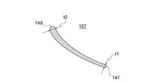
Next, a second embodiment of the present invention will be described with reference to FIG. FIG. 4 is a cross-sectional view perpendicular to the longitudinal direction of the wind vane, according to Embodiment 2 of the present invention. Note that the air conditioner of the second embodiment is different from the first embodiment only in the configuration of the wind vane described later, and the other configurations are the same as those in the first embodiment.
本実施の形態2の空気調和機の風向ベーン107の上流端149は、図4の断面においてみて、ラウンド形状に形成されている。また、風向ベーン107における肉厚(湾曲を構成している円の半径方向の厚み)は、上流端149において最大肉厚t2となり、下流端147において最小肉厚t1となる。
The
このように構成された本実施の形態2に係る空気調和機においても、上記実施の形態1と同様な利点が得られている。さらに加えて、本実施の形態2においては、風向ベーン107がラウンド形状の上流端149を備えることから、風向ベーン107の上流端149における気流の変化を小さくできることから気流の剥離を防止することができ、さらに、気流において流入角IFが変化しても広範な流入角IFにわたって気流の剥離を防止することができる。さらに、風向ベーン107の肉厚を下流端147で最小とすることで、後流幅を小さくすることができるため、後流で発生する混合損失を低減できる。これによっても、圧力損失を低減し、省エネ性能の改善、送風音の低減を図ることができる。
Also in the air conditioner according to the second embodiment configured as described above, the same advantages as those of the first embodiment are obtained. In addition, in the second embodiment, since the
実施の形態3.
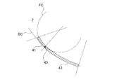
次に、図5に基づいて本発明の実施の形態3について説明する。図5は、本発明の実施の形態3に関し、風向ベーンの湾曲態様を説明する図である。なお、本実施の形態3の空気調和機は、風向ベーンの後述する構成だけが上記実施の形態1又は2と異なっており、他の構成は実施の形態1又は2と同様であるものとする。
Next, a third embodiment of the present invention will be described with reference to FIG. FIG. 5 is a diagram for explaining a curved aspect of the wind direction vane in the third embodiment of the present invention. The air conditioner of the third embodiment is different from the first or second embodiment only in the configuration of the wind vane, which will be described later, and the other configuration is the same as that of the first or second embodiment. .
本実施の形態3の空気調和機の風向ベーン207は、第1湾曲部41と、第2湾曲部43と、さらに加えて、平板部242を有している。平板部242は、第1湾曲部41のさらに上流側に位置している。平板部242は、図5においてみて、第1湾曲部41と平板部242との境界部(変曲点部)245における第1円FCの接線TLに沿って直線的に延びる平板状の部分である。また、言い換えると、風向ベーン207は、上流端49から下流端47までの間に、平板部242、第1湾曲部41及び第2湾曲部43をこの順で有している。
The
このように構成された本実施の形態3に係る空気調和機においても、上記実施の形態1と同様な利点が得られている。さらに加えて、本実施の形態3においては、気流がベーンの上流端49に衝突した後、すぐに、風向ベーン207の湾曲部を流れないで済むので、上流端49に衝突直後の気流が風向ベーン207に張り付いて流れやすく、気流の剥離を防止することができる。これによっても、気流の剥離による圧力損失を低減し、省エネ性能の改善、送風音の低減を図ることも可能となっている。
Also in the air conditioner according to the third embodiment configured as described above, the same advantages as those of the first embodiment are obtained. In addition, in the third embodiment, since the airflow does not flow through the curved portion of the
実施の形態4.
次に、図6に基づいて本発明の実施の形態4について説明する。図6は、本発明の実施の形態4に関する、風向ベーンの長手方向に垂直な断面図である。なお、本実施の形態4の空気調和機は、風向ベーンの後述する構成だけが上記実施の形態1〜3と異なっており、他の構成は実施の形態1〜3と同様であるものとする。Embodiment 4 FIG.
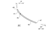
Next, a fourth embodiment of the present invention will be described based on FIG. FIG. 6 is a cross-sectional view perpendicular to the longitudinal direction of the wind direction vane, according to Embodiment 4 of the present invention. Note that the air conditioner of the fourth embodiment is different from the first to third embodiments only in the configuration of the wind direction vane described later, and the other configurations are the same as those of the first to third embodiments. .
本実施の形態4の空気調和機の風向ベーン307は、上記実施の形態1における風向ベーン7において、具体的に流入角IFを10°〜25°とし、流出角OFを20°〜40°としたものである。つまり、風向ベーン307は、水平吹き時の流入角IFを10°〜25°としたものである。流入角IFが25°を超えると、風向ベーン307の凸面7a側で気流の剥離が生じやすくなり、また、流入角IFが10°未満であると、風向ベーン307を下吹きの態様に設置した時に流入角IFが負の値の角度となり、凹面7b側で気流の剥離が生じやすくなる。
The
このように構成された本実施の形態4に係る空気調和機においても、上記実施の形態1と同様な利点が得られている。さらに加えて、本実施の形態4においては、流入角IFを10°〜25°としたことで、水平吹き時の凸面7a側での気流の剥離と、下吹き時の凹面7b側での気流の剥離とを抑制する風向ベーン構造を得ることが可能となっている。
In the air conditioner according to the fourth embodiment configured as described above, the same advantages as those of the first embodiment are obtained. In addition, in the fourth embodiment, the inflow angle IF is set to 10 ° to 25 °, so that the airflow on the
実施の形態5.
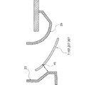
次に、図7に基づいて本発明の実施の形態5について説明する。図7は、本発明の実施の形態5に関し、水平吹き状態の風向ベーンの周辺部を、風向ベーンの長手方向に垂直な断面で示す図である。なお、本実施の形態5の空気調和機は、後述する構成以外は、実施の形態1〜4の何れかの構成と同様であるものとする。
Next, a fifth embodiment of the present invention will be described with reference to FIG. FIG. 7 is a view showing a peripheral portion of a wind direction vane in a horizontal blowing state in a cross section perpendicular to the longitudinal direction of the wind direction vane, according to
本実施の形態5の空気調和機では、風向ベーン7,107,207,307の境界部45が、水平吹き状態の風向ベーン上における内側風路壁23と最も接近した部分である最接近部に一致するか、または、境界部45が風向ベーン上におけるその最接近部よりも下流に位置する。なお、図7は、図示例として、風向ベーン7において境界部45が上記最接近部に一致している態様を示している。
In the air conditioner of the fifth embodiment, the
このように構成された本実施の形態5に係る空気調和機においても、対応する上記実施の形態1〜4と同様な利点が得られている。さらに加えて、本実施の形態5においては、次のような利点がある。すなわち、風向ベーンが内側風路壁23と最も接近した位置よりも上流側の領域は、風向ベーンの凸面が内側風路壁23との間で風路を構成することとなるので、第1湾曲部41の曲率が大きくても、風向ベーンの凸面7a側における気流の剥離を防止することができる。すなわち、曲率が大きな第1湾曲部41を用いて、上述した実施の形態1〜4の利点を得るに際して、凸面7a側での気流の剥離がより生じにくい態様で第1湾曲部41を活用することが可能となっている。
Also in the air conditioner according to the fifth embodiment configured as described above, advantages similar to those of the corresponding first to fourth embodiments are obtained. In addition, the fifth embodiment has the following advantages. That is, in the region upstream of the position where the wind direction vane is closest to the inner
実施の形態6.
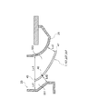
次に、図8に基づいて本発明の実施の形態6について説明する。図8は、本発明の実施の形態6に関する風向ベーンの周辺部を、風向ベーンの長手方向に垂直な断面で示す図である。なお、本実施の形態6の空気調和機は、後述する構成以外は、実施の形態1〜5の何れかの構成と同様であるものとする。Embodiment 6 FIG.
Next, a sixth embodiment of the present invention will be described with reference to FIG. FIG. 8 is a view showing a peripheral portion of the wind direction vane according to Embodiment 6 of the present invention in a cross section perpendicular to the longitudinal direction of the wind direction vane. In addition, the air conditioner of this Embodiment 6 shall be the same as that of the structure in any one of Embodiments 1-5 except the structure mentioned later.
本実施の形態6の空気調和機では、水平吹き時における風向ベーン7,107,207,307及び内側風路壁23により構成される内側風路551と、水平吹き時における風向ベーン7,107,207,307及び外側風路壁25により構成される外側風路553とが、共に、縮小形状となるように構成されている。すなわち、風向ベーンの上流端49と外側風路壁25との最短距離Lu1が、下流端47と外側風路壁25との最短距離Lu2より大きく、且つ、上流端49と内側風路壁23との最短距離Ld1が、それより下流側の風向ベーンから内側風路壁23までの最短距離Ld2より大きくなるように構成されている。なお、最短距離Ld2は、風向ベーンが内側風路壁23と最も接近した位置における風向ベーンと内側風路壁23との間隔であり、図8では、境界部45と内側風路壁23との間隔を図示例としている。
In the air conditioner of the sixth embodiment, the
このように構成された本実施の形態6に係る空気調和機においても、対応する上記実施の形態1〜5と同様な利点が得られている。さらに加えて、本実施の形態6においては、次のような利点がある。すなわち、内側風路551及び外側風路553の各風路が縮小形状となっているため、気流が安定しやすく、風向ベーン上、及び、内側風路壁23・外側風路壁25上での気流の剥離が発生しにくくなる利点が得られる。
Also in the air conditioner according to the sixth embodiment configured as described above, advantages similar to those of the corresponding first to fifth embodiments are obtained. In addition, the sixth embodiment has the following advantages. That is, since each of the
実施の形態7.
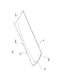
次に、図9に基づいて本発明の実施の形態7について説明する。図9は、本発明の実施の形態7に関する、風向ベーンの斜視図である。なお、本実施の形態7の空気調和機は、後述する構成以外は、実施の形態1〜6の何れかの構成と同様であるものとする。
Next, a seventh embodiment of the present invention will be described with reference to FIG. FIG. 9 is a perspective view of a wind direction vane according to
本実施の形態7の空気調和機における風向ベーン607は、第1湾曲部41と第2湾曲部43との境界部45が、ベーン長手方向(上流端及び下流端の延びる方向)にわたって下流端47や上流端49に対する位置が変化しているように構成されている。特に、図9の図示例においては、境界部45は、その長手方向中央領域655が、長手方向両端領域657よりも上流端49側に近くなるような態様で緩やかに湾曲している。
In the
このように構成された本実施の形態7に係る空気調和機においても、対応する上記実施の形態1〜6と同様な利点が得られている。さらに加えて、本実施の形態7においては、次のような利点がある。すなわち、境界部45の位置を長手方向にわたって変えておくことで、風向ベーン607の凸面7a側で気流の剥離が発生するとしても、その剥離発生位置を風向ベーン607の長手方向に応じてずらすことができるので、剥離によって発生する渦の成長を抑制することができ、剥離領域も小さくできる。
Also in the air conditioner according to the seventh embodiment configured as described above, the same advantages as those of the corresponding first to sixth embodiments are obtained. In addition, the seventh embodiment has the following advantages. That is, by changing the position of the
なお、上述した実施の形態5において、本実施の形態7のような境界部がベーン長手方向にわたって位置が変化している風向ベーンを用いる場合には、上流端側に最も近づいている境界部の部分に関してみて、その境界部の部分が、水平吹き状態の風向ベーン上における内側風路壁と最も接近した部分である最接近部に一致するか、または、その最接近部よりも下流に位置するように構成するものとする。 In the fifth embodiment described above, when the wind direction vane whose position is changed in the vane longitudinal direction as in the seventh embodiment, the boundary portion closest to the upstream end side is used. As for the part, the boundary part coincides with the closest part which is the part closest to the inner wind channel wall on the wind vane in the horizontal blowing state, or is located downstream of the closest part. It shall be constituted as follows.
以上、好ましい実施の形態を参照して本発明の内容を具体的に説明したが、本発明の基本的技術思想及び教示に基づいて、当業者であれば、種々の改変態様を採り得ることは自明である。 Although the contents of the present invention have been specifically described with reference to the preferred embodiments, various modifications can be made by those skilled in the art based on the basic technical idea and teachings of the present invention. It is self-explanatory.
例えば、本発明における空気調和機は、四つの吸込口を有することには限定されず、一つの吸込口だけを有している構成でも良いし、任意の複数の数の吸込口を有している構成でも良い。また、本発明では、吹出口の設置数も同様に、限定されない。そして、風向ベーンの設置態様は、複数個の吹出口が設置されている場合、それら複数の吹出口のうちの、一つの吹出口にだけ設置されている態様でもよく、あるいは、一部の複数の吹出口にだけ設置されている態様でもよく、あるいは、全部の吹出口に設置されている態様でもよい。上述した実施の形態は、かかる態様のうちの、全部の吹出口に風向ベーンが設置されている態様を例に説明した。 For example, the air conditioner in the present invention is not limited to having four suction ports, and may have a configuration having only one suction port, or may have any number of suction ports. It may be configured. Moreover, in this invention, the number of installation of a blower outlet is not limited similarly. And the installation aspect of a wind direction vane may be an aspect installed only in one blower outlet among those blower outlets, when a plurality of blower outlets are installed. The aspect installed only in the blower outlet may be sufficient, or the aspect installed in all the blower outlets may be sufficient. Embodiment mentioned above demonstrated the example in which the wind direction vane was installed in all the blower outlets among such aspects.
また、上述した実施の形態は、天井埋込型の空気調和機を例に説明したが、本発明はこれに限定されたものではなく、吸込口と吹出口との間で熱交換を行う装置に広く適用することができ、例を示すと、冷凍サイクル装置を構成する室内機、例えば空気調和機の室内機を挙げることができる。また、吸込口から吹出口までの気流を発生させるファンは、必ずしも吸込口から吹出口までの空気の流動路中に配置されていることには限定されない。 Moreover, although embodiment mentioned above demonstrated the example to the ceiling embedded type air conditioner, this invention is not limited to this, The apparatus which performs heat exchange between a suction inlet and a blower outlet For example, an indoor unit constituting the refrigeration cycle apparatus, for example, an indoor unit of an air conditioner can be given. Further, the fan that generates the airflow from the suction port to the blowout port is not necessarily limited to being disposed in the air flow path from the suction port to the blowout port.
1 本体、5 熱交換器、7,107,207,307,607 風向ベーン、17 吸込グリル(吸込口)、21 パネル吹出口(吹出口)、23 内側風路壁、25 外側風路壁、31 室内(対象空間)、41 第1湾曲部、43 第2湾曲部、45 境界部、47,147 下流端、49,149 上流端、242 平板部、551 内側風路、553 外側風路、655 長手方向中央領域、657 長手方向両端領域。 DESCRIPTION OF SYMBOLS 1 Main body, 5 Heat exchanger, 7, 107, 207, 307, 607 Wind direction vane, 17 Suction grill (suction port), 21 Panel blower outlet (blower), 23 Inner wind channel wall, 25 Outer wind channel wall, 31 Indoor (target space), 41 1st bending portion, 43 2nd bending portion, 45 boundary portion, 47, 147 downstream end, 49, 149 upstream end, 242 flat plate portion, 551 inner air passage, 553 outer air passage, 655 longitudinal Central region in the direction, 657 Both end regions in the longitudinal direction.
Claims (6)
前記吹出口に可動に設けられた風向ベーンとを備え、
前記風向ベーンは、第1湾曲部と、第2湾曲部とを含み、
前記第1湾曲部は、前記第2湾曲部よりも上流に位置しており、該第1湾曲部の厚さ方向の中心線の曲率は、該第2湾曲部の厚さ方向の中心線の曲率よりも大きく、
前記風向ベーンは、平板部を更に含み、
前記平板部は、前記第1湾曲部の上流に位置している、
空気調和機の室内機。 A heat exchanger disposed in the flow path of air that is housed in the body and is sucked into the main body from the suction port and blown out from the blowout port to the target space;
A wind direction vane movably provided at the air outlet,
The wind direction vane includes a first bending portion and a second bending portion,
The first curved portion, the second is located above flow than the curved portion, the curvature of the thickness direction of the center line of the first curved portion has a center line in the thickness direction of the second curved portion Larger than the curvature of
The wind direction vane further includes a flat plate portion,
Said plate is located on the upstream of the first bending portion,
Air conditioner indoor unit.
請求項1の空気調和機の室内機。 Does the boundary between the first curved part and the second curved part coincide with the closest part which is the part closest to the inner air passage wall of the outlet on the wind direction vane in a horizontal blowing state, Or located downstream of the closest part,
The indoor unit of the air conditioner of Claim 1.
請求項1又は2の空気調和機の室内機。 The first bending portion and the second bending portion are smoothly connected;
The indoor unit of the air conditioner according to claim 1 or 2.
請求項1又は3の空気調和機の室内機。 The wind direction vane is configured to have an outflow angle of 20 ° to 40 ° and an inflow angle of 10 ° to 25 °.
The indoor unit of the air conditioner according to claim 1 or 3.
請求項1乃至4の何れか一項の空気調和機の室内機。 An inner air passage composed of the wind direction vane and the inner air passage wall of the air outlet arranged at an outlet angle of 20 ° to 40 °, and an outer side constituted of the air vane and the outer air passage wall of the air outlet The air path is configured to be a reduced shape.
The indoor unit of the air conditioner as described in any one of Claims 1 thru | or 4 .
請求項1乃至5の何れか一項の空気調和機の室内機。 The position of the boundary between the first curved portion and the second curved portion in the wind direction vane changes with respect to the downstream end and the upstream end over the longitudinal direction.
The indoor unit of the air conditioner as described in any one of Claims 1 thru | or 5 .
Applications Claiming Priority (3)
| Application Number | Priority Date | Filing Date | Title |
|---|---|---|---|
| PCT/JP2012/077979 WO2014068654A1 (en) | 2012-10-30 | 2012-10-30 | Air conditioner |
| JPPCT/JP2012/077979 | 2012-10-30 | ||
| PCT/JP2013/078689 WO2014069301A1 (en) | 2012-10-30 | 2013-10-23 | Air conditioner |
Publications (2)
| Publication Number | Publication Date |
|---|---|
| JPWO2014069301A1 JPWO2014069301A1 (en) | 2016-09-08 |
| JP6324316B2 true JP6324316B2 (en) | 2018-05-16 |
Family
ID=50626633
Family Applications (1)
| Application Number | Title | Priority Date | Filing Date |
|---|---|---|---|
| JP2014544449A Expired - Fee Related JP6324316B2 (en) | 2012-10-30 | 2013-10-23 | Air conditioner indoor unit |
Country Status (5)
| Country | Link |
|---|---|
| US (1) | US9995504B2 (en) |
| EP (1) | EP2918936B1 (en) |
| JP (1) | JP6324316B2 (en) |
| CN (2) | CN104769368B (en) |
| WO (2) | WO2014068654A1 (en) |
Families Citing this family (12)
| Publication number | Priority date | Publication date | Assignee | Title |
|---|---|---|---|---|
| JP4952775B2 (en) * | 2009-11-05 | 2012-06-13 | ダイキン工業株式会社 | Air conditioner indoor unit |
| USD761411S1 (en) * | 2014-04-17 | 2016-07-12 | Stego-Holding Gmbh | Fan |
| JP6369684B2 (en) * | 2014-10-10 | 2018-08-08 | 株式会社富士通ゼネラル | Embedded ceiling air conditioner |
| JP6223953B2 (en) * | 2014-12-02 | 2017-11-01 | 三菱重工サーマルシステムズ株式会社 | Air conditioner |
| JP6233398B2 (en) * | 2015-12-22 | 2017-11-22 | ダイキン工業株式会社 | Indoor unit of air conditioner |
| CN111886456B (en) * | 2018-03-19 | 2022-10-21 | 夏普株式会社 | Fan blade, air conditioner and dehumidifier |
| EP3842703A4 (en) * | 2018-08-21 | 2022-03-30 | Hitachi-Johnson Controls Air Conditioning, Inc. | Indoor unit for air conditioner |
| CN110260502B (en) * | 2019-06-21 | 2021-10-26 | 广东美的制冷设备有限公司 | Air deflector of air conditioner and air conditioner |
| JP7082293B2 (en) * | 2019-09-17 | 2022-06-08 | ダイキン工業株式会社 | Air conditioning indoor unit and air conditioner |
| TR202007646A2 (en) | 2020-05-15 | 2021-09-21 | Daikin Isitma Ve Sogutma Sistemleri Sanayi Ticaret Anonim Sirketi | A AIR CONDITIONING DEVICE THAT ENABLES VERSATILE USAGE |
| KR102860418B1 (en) | 2020-06-11 | 2025-09-15 | 엘지전자 주식회사 | Indoor unit of air conditioner |
| CN115419955B (en) * | 2022-09-02 | 2024-07-23 | 珠海格力电器股份有限公司 | Air condensing units shell structure and air condensing units |
Family Cites Families (21)
| Publication number | Priority date | Publication date | Assignee | Title |
|---|---|---|---|---|
| US2123287A (en) * | 1934-11-22 | 1938-07-12 | Eugene J Ney | Combination ventilator |
| JPH03267651A (en) * | 1990-03-16 | 1991-11-28 | Hitachi Ltd | Air-conditioner and blow-off wind direction control method |
| US5722484A (en) * | 1995-12-26 | 1998-03-03 | Carrier Corporation | Louver assembly for fan discharge duct |
| JP3392644B2 (en) * | 1996-06-26 | 2003-03-31 | 東芝キヤリア株式会社 | Air conditioner indoor unit |
| US6217285B1 (en) * | 1996-08-08 | 2001-04-17 | Sanyo Electric Co., Ltd. | Impeller for a centrifugal blower |
| JP3116874B2 (en) | 1997-10-14 | 2000-12-11 | ダイキン工業株式会社 | Air outlet structure of air conditioner |
| JP3277868B2 (en) * | 1997-11-26 | 2002-04-22 | ダイキン工業株式会社 | Air conditioner indoor unit |
| JPH11248188A (en) * | 1998-03-03 | 1999-09-14 | Mitsubishi Electric Corp | Indoor air outlet structure in air conditioner |
| JP3885846B2 (en) * | 1998-04-17 | 2007-02-28 | 株式会社富士通ゼネラル | Air conditioner |
| JP2000065418A (en) * | 1998-08-25 | 2000-03-03 | Hitachi Ltd | Air conditioner |
| JP3438684B2 (en) * | 1999-11-05 | 2003-08-18 | ダイキン工業株式会社 | Ceiling embedded air conditioner |
| JP2003294303A (en) * | 2002-04-01 | 2003-10-15 | Mitsubishi Heavy Ind Ltd | Wind direction control plate, guide plate, indoor unit, and air conditioner |
| JP3820182B2 (en) * | 2002-05-10 | 2006-09-13 | 三菱重工業株式会社 | Air conditioner louver, airflow control structure for air conditioner, and air conditioner |
| ITVI20030021U1 (en) * | 2003-04-22 | 2004-10-23 | Xiang Srl Ora Xiang Spa | CEILING AIR CONDITIONER |
| EP1589292A1 (en) * | 2004-04-23 | 2005-10-26 | Unico Consumer Products Co., Ltd. | Ceiling-recessed air treatment apparatus |
| DE102006025185A1 (en) * | 2005-05-31 | 2007-02-22 | Technological Resources Pty. Ltd. | Apparatus for blowing gas into a vessel, especially a direct smelting vessel, comprises a swirler with vanes that have a straight front section, a spiral rear section and a smoothly changing transitional region |
| JP2007024345A (en) | 2005-07-12 | 2007-02-01 | Mitsubishi Electric Corp | Air conditioner |
| JP4335937B2 (en) * | 2007-10-23 | 2009-09-30 | シャープ株式会社 | Air conditioner |
| JP4858506B2 (en) * | 2008-07-29 | 2012-01-18 | ダイキン工業株式会社 | Air conditioner |
| JP5456402B2 (en) * | 2009-07-27 | 2014-03-26 | 三洋電機株式会社 | Embedded ceiling air conditioner |
| WO2011040519A1 (en) * | 2009-09-30 | 2011-04-07 | ダイキン工業株式会社 | Air conditioning device |
-
2012
- 2012-10-30 WO PCT/JP2012/077979 patent/WO2014068654A1/en not_active Ceased
-
2013
- 2013-10-23 EP EP13851221.5A patent/EP2918936B1/en active Active
- 2013-10-23 US US14/430,232 patent/US9995504B2/en active Active
- 2013-10-23 WO PCT/JP2013/078689 patent/WO2014069301A1/en not_active Ceased
- 2013-10-23 JP JP2014544449A patent/JP6324316B2/en not_active Expired - Fee Related
- 2013-10-23 CN CN201380057001.3A patent/CN104769368B/en not_active Expired - Fee Related
- 2013-10-30 CN CN201320676732.3U patent/CN203595181U/en not_active Expired - Lifetime
Also Published As
| Publication number | Publication date |
|---|---|
| EP2918936A4 (en) | 2016-07-27 |
| WO2014069301A1 (en) | 2014-05-08 |
| WO2014068654A1 (en) | 2014-05-08 |
| EP2918936A1 (en) | 2015-09-16 |
| CN203595181U (en) | 2014-05-14 |
| JPWO2014069301A1 (en) | 2016-09-08 |
| US9995504B2 (en) | 2018-06-12 |
| EP2918936B1 (en) | 2022-12-14 |
| US20150253032A1 (en) | 2015-09-10 |
| CN104769368B (en) | 2018-05-08 |
| CN104769368A (en) | 2015-07-08 |
Similar Documents
| Publication | Publication Date | Title |
|---|---|---|
| JP6324316B2 (en) | Air conditioner indoor unit | |
| JP6248486B2 (en) | Air conditioner duct type indoor unit | |
| JP6578907B2 (en) | Embedded ceiling air conditioner | |
| JP6167780B2 (en) | Fan unit and air conditioner | |
| JP2016142431A (en) | Air conditioner | |
| JP2007170331A (en) | Indoor unit of turbo fan and air conditioner using the same | |
| JP6008993B2 (en) | Air conditioner | |
| KR20140125522A (en) | turbo fan | |
| JP6139669B2 (en) | Air conditioner | |
| JP5293684B2 (en) | Air conditioner indoor unit | |
| KR102136879B1 (en) | turbo fan and ceiling type air conditioner using thereof | |
| JP6135125B2 (en) | Indoor unit | |
| EP3130860B1 (en) | Air conditioner | |
| JP5590016B2 (en) | Turbo fan, air conditioner | |
| JP6211101B2 (en) | Centrifugal fan, air conditioner and air purifier | |
| WO2018029878A1 (en) | Indoor unit and air-conditioning device | |
| KR20140105085A (en) | ceiling type air conditioner | |
| JP6153141B2 (en) | Air conditioner | |
| JPWO2018002987A1 (en) | Multi-blade fan and air conditioner | |
| JPWO2014207909A1 (en) | Air conditioner | |
| JPWO2013124877A1 (en) | Air conditioner outdoor unit | |
| JP2010084690A (en) | Air conditioner |
Legal Events
| Date | Code | Title | Description |
|---|---|---|---|
| A02 | Decision of refusal |
Free format text: JAPANESE INTERMEDIATE CODE: A02 Effective date: 20160524 |
|
| A521 | Request for written amendment filed |
Free format text: JAPANESE INTERMEDIATE CODE: A523 Effective date: 20160727 |
|
| A911 | Transfer to examiner for re-examination before appeal (zenchi) |
Free format text: JAPANESE INTERMEDIATE CODE: A911 Effective date: 20160804 |
|
| A912 | Re-examination (zenchi) completed and case transferred to appeal board |
Free format text: JAPANESE INTERMEDIATE CODE: A912 Effective date: 20161021 |
|
| RD04 | Notification of resignation of power of attorney |
Free format text: JAPANESE INTERMEDIATE CODE: A7424 Effective date: 20170407 |
|
| A521 | Request for written amendment filed |
Free format text: JAPANESE INTERMEDIATE CODE: A523 Effective date: 20170810 |
|
| A521 | Request for written amendment filed |
Free format text: JAPANESE INTERMEDIATE CODE: A523 Effective date: 20171129 |
|
| A61 | First payment of annual fees (during grant procedure) |
Free format text: JAPANESE INTERMEDIATE CODE: A61 Effective date: 20180410 |
|
| R150 | Certificate of patent or registration of utility model |
Ref document number: 6324316 Country of ref document: JP Free format text: JAPANESE INTERMEDIATE CODE: R150 |
|
| R250 | Receipt of annual fees |
Free format text: JAPANESE INTERMEDIATE CODE: R250 |
|
| R250 | Receipt of annual fees |
Free format text: JAPANESE INTERMEDIATE CODE: R250 |
|
| R250 | Receipt of annual fees |
Free format text: JAPANESE INTERMEDIATE CODE: R250 |
|
| LAPS | Cancellation because of no payment of annual fees |