JP6324061B2 - Image forming apparatus - Google Patents
Image forming apparatus Download PDFInfo
- Publication number
- JP6324061B2 JP6324061B2 JP2013267134A JP2013267134A JP6324061B2 JP 6324061 B2 JP6324061 B2 JP 6324061B2 JP 2013267134 A JP2013267134 A JP 2013267134A JP 2013267134 A JP2013267134 A JP 2013267134A JP 6324061 B2 JP6324061 B2 JP 6324061B2
- Authority
- JP
- Japan
- Prior art keywords
- exposure
- signal
- count value
- image forming
- forming apparatus
- Prior art date
- Legal status (The legal status is an assumption and is not a legal conclusion. Google has not performed a legal analysis and makes no representation as to the accuracy of the status listed.)
- Active
Links
Images


Classifications
-
- G—PHYSICS
- G03—PHOTOGRAPHY; CINEMATOGRAPHY; ANALOGOUS TECHNIQUES USING WAVES OTHER THAN OPTICAL WAVES; ELECTROGRAPHY; HOLOGRAPHY
- G03G—ELECTROGRAPHY; ELECTROPHOTOGRAPHY; MAGNETOGRAPHY
- G03G15/00—Apparatus for electrographic processes using a charge pattern
- G03G15/04—Apparatus for electrographic processes using a charge pattern for exposing, i.e. imagewise exposure by optically projecting the original image on a photoconductive recording material
- G03G15/043—Apparatus for electrographic processes using a charge pattern for exposing, i.e. imagewise exposure by optically projecting the original image on a photoconductive recording material with means for controlling illumination or exposure
-
- G—PHYSICS
- G03—PHOTOGRAPHY; CINEMATOGRAPHY; ANALOGOUS TECHNIQUES USING WAVES OTHER THAN OPTICAL WAVES; ELECTROGRAPHY; HOLOGRAPHY
- G03G—ELECTROGRAPHY; ELECTROPHOTOGRAPHY; MAGNETOGRAPHY
- G03G15/00—Apparatus for electrographic processes using a charge pattern
- G03G15/55—Self-diagnostics; Malfunction or lifetime display
- G03G15/553—Monitoring or warning means for exhaustion or lifetime end of consumables, e.g. indication of insufficient copy sheet quantity for a job
- G03G15/556—Monitoring or warning means for exhaustion or lifetime end of consumables, e.g. indication of insufficient copy sheet quantity for a job for toner consumption, e.g. pixel counting, toner coverage detection or toner density measurement
Description
本発明は記録媒体に画像を形成する画像形成装置に関する。 The present invention relates to an image forming apparatus that forms an image on a recording medium.
電子写真方式や静電記録方式の画像形成装置において、転写メモリによる画像濃度差を抑制するため、露光手段でトナー像を形成する部分以外の領域(非印字部)にもトナー像形成部を露光する際の露光量よりも弱い露光量で露光する方法が知られている。例えば特許文献1に記載されている技術である。以後、このトナー像形成部以外にも露光することをバックグラウンド露光と称する。
In an electrophotographic image forming apparatus or electrostatic recording image forming apparatus, in order to suppress a difference in image density due to a transfer memory, the toner image forming unit is exposed to an area (non-printing part) other than the part where the toner image is formed by the exposure unit. A method is known in which exposure is performed with an exposure amount that is weaker than the exposure amount at the time of exposure. For example, it is a technique described in
また、帯電ローラにDC電圧を印加して感光体を帯電するDC接触帯電方式において、高圧ユニットの小型化を狙って、帯電ローラに印加するDC電圧を所定の値に固定する構成が用いられることもある。この際に、感光体の膜厚変化や使用環境の変化による帯電後の感光体表面電位の変化に対応するため、バックグラウンド露光を行うことも知られている(特許文献2参照)。 In the DC contact charging method in which a DC voltage is applied to the charging roller to charge the photosensitive member, a configuration in which the DC voltage applied to the charging roller is fixed to a predetermined value is used in order to reduce the size of the high-voltage unit. There is also. At this time, it is also known to perform background exposure in order to cope with a change in the surface potential of the photoconductor after charging due to a change in the film thickness of the photoconductor or a change in use environment (see Patent Document 2).
バックグラウンド露光の方法としては、ひとつには弱い光量で画像領域の全域を露光する手法(以下、アナログバックグラウンド露光と称する)がある。 As a background exposure method, there is a method (hereinafter referred to as analog background exposure) in which the entire image area is exposed with a weak light quantity.
また別の方法としては、単位領域あたりの露光時間を、トナー像形成部(印画部)に露光する時間よりも短い時間として、非印画部をバックグラウンド露光する手法(以下、デジタルバックグラウンド露光と称する)が知られている(特許文献3参照)。デジタルバックグラウンド露光は、露光手段に用いるレーザ素子の特性で、弱い光量で露光が行なえない時などに有効である。 As another method, the exposure time per unit area is set to be shorter than the time for exposing the toner image forming unit (printing unit), and the non-printing unit is subjected to background exposure (hereinafter referred to as digital background exposure). Is known) (see Patent Document 3). Digital background exposure is effective when the exposure cannot be performed with a weak amount of light due to the characteristics of the laser element used for the exposure means.
また、トナー使用量を予測する方法として、露光手段に備えられたレーザ素子を制御するレーザドライバに入力される電気信号(ビデオ信号)をカウントするカウント手段を用いる方法が知られている。カウント手段は、予め定められた画像形成部内で特定の数だけビデオ信号をサンプルし、ビデオ信号がONである数をカウントする。サンプル数とカウント値の比率から、印刷画像の印画率を計算し、トナー使用量を予測するものである。以下、上記方法を、ビデオカウントトナー使用量予測検知と称する。実際に、レーザドライバに入力される信号を直接計測するため、精度よくトナー使用量を検知が可能となる。(特許文献4参照) Further, as a method for predicting the toner usage amount, a method using a counting unit that counts an electric signal (video signal) input to a laser driver that controls a laser element provided in the exposure unit is known. The counting means samples a video signal by a specific number in a predetermined image forming unit, and counts the number of video signals that are ON. From the ratio between the number of samples and the count value, the printing rate of the printed image is calculated to predict the toner usage. Hereinafter, the above method is referred to as video count toner usage prediction detection. Actually, since the signal input to the laser driver is directly measured, it is possible to accurately detect the amount of toner used. (See Patent Document 4)
しかしながら、上記のデジタルバックグラウンド露光を搭載した画像形成装置において、上記ビデオ信号トナー使用量予測検知を行なうと、以下の課題が生じることがあった。 However, in the image forming apparatus equipped with the digital background exposure, when the video signal toner usage prediction is detected, the following problems may occur.
前記のカウント手段は、レーザドライバに入力されるビデオ信号がどのような信号であっても計測する。そのため、トナー像を形成しない非印画部に露光する際にレーザドライバに入力される信号も計測することになる。しかしながら、この非印画部への露光ではトナーを消費しない。そのため、ビデオカウントトナー使用量予測検知でトナー使用量を予測しようとしたとき、非印画部のビデオ信号の分を余計に計測してしまい、実際のトナー使用量よりも多いと検知することがあった。 The counting means measures whatever video signal is input to the laser driver. For this reason, a signal input to the laser driver when the non-printing portion where no toner image is formed is exposed is also measured. However, the toner is not consumed in the exposure to the non-printing portion. For this reason, when trying to predict toner usage by video count toner usage prediction detection, the amount of video signal in the non-printing area is excessively measured and may be detected as being greater than the actual toner usage. It was.
よって、本発明の目的は、単位領域あたりの非印画部の露光時間を、単位領域あたりの印画部の露光時間よりも短くする画像形成装置において、露光を指示する電気信号によって現像剤の使用量を求めることである。 Therefore, an object of the present invention is to use the amount of developer by an electric signal instructing exposure in an image forming apparatus in which the exposure time of the non-printed area per unit area is shorter than the exposure time of the printed area per unit area. Is to seek.
上記課題を解決するための本発明の代表的な構成は、
像担持体と、
前記像担持体を帯電する帯電手段と、
前記帯電手段で帯電された前記像担持体を露光することで静電潜像を形成する露光手段であって、像担持体の単位領域ごとに断続的な光の照射を行う露光手段と、
現像剤を収容する現像剤収容部を有し、前記静電潜像を現像剤によって現像する現像手段と、
前記露光手段に露光を指示する画像データに対応した電気信号を出力する信号出力部であって、現像剤像が形成される像担持体の印画部を露光させる第1信号と、現像剤像が形成されない像担持体の非印画部を露光する第2信号と、を出力する信号出力部と、を有し、
前記第2信号に基づく前記像担持体の単位領域あたりの露光時間が、前記第1信号に基づく前記像担持体の単位領域あたりの露光時間よりも短い画像形成装置であって、前記信号出力部から出力された電気信号が入力され、所定のタイミングでサンプリングを行って前記第1信号および前記第2信号をカウントし、前記第1信号のカウント値及び前記第2信号のカウント値を含むカウント値Yを出力するカウント手段と、
前記露光手段が露光する前記像担持体の露光領域の全てを前記第1信号のみによって露光した場合に前記カウント手段がカウントするカウント値をカウント値Z、前記露光領域の全てを前記第2信号のみによって露光した場合に前記カウント手段がカウントするカウント値をカウント値BGとした際に、前記カウント手段がカウントした前記カウント値Y、前記カウント値Z、及び、前記カウント値BGに基いて前記現像手段による現像剤の使用量に対応するカウント値を求める演算を行う演算手段と、
を備えることを特徴とする画像形成装置。
A typical configuration of the present invention for solving the above problems is as follows.
An image carrier;
Charging means for charging the image carrier;
An exposure unit that forms an electrostatic latent image by exposing the image carrier charged by the charging unit, the exposure unit performing intermittent light irradiation for each unit region of the image carrier;
A developer containing a developer containing portion, and developing means for developing the electrostatic latent image with a developer;
A signal output unit that outputs an electrical signal corresponding to image data instructing exposure to the exposure unit, the first signal for exposing the printing unit of the image carrier on which the developer image is formed, and the developer image A signal output unit that outputs a second signal for exposing a non-printing part of the image carrier that is not formed, and
An image forming apparatus in which an exposure time per unit area of the image carrier based on the second signal is shorter than an exposure time per unit area of the image carrier based on the first signal, the signal output unit The electric signal output from the signal is input , sampling is performed at a predetermined timing to count the first signal and the second signal, and the count value includes the count value of the first signal and the count value of the second signal Counting means for outputting Y;
When all the exposure areas of the image carrier exposed by the exposure means are exposed only by the first signal, the count value counted by the counting means is a count value Z, and all the exposure areas are only the second signal. When the count value counted by the counting means when the exposure is performed is set to the count value BG, the developing means is based on the count value Y, the count value Z, and the count value BG counted by the counting means. Calculating means for calculating a count value corresponding to the amount of developer used by
An image forming apparatus comprising:
本発明によれば、単位領域あたりの非印画部の露光時間を、単位領域あたりの印画部の露光時間よりも短くする画像形成装置において、露光を指示する電気信号によって現像剤の使用量を求めることができる。 According to the present invention, in the image forming apparatus in which the exposure time of the non-printed area per unit area is shorter than the exposure time of the printed area per unit area, the usage amount of the developer is obtained by an electrical signal instructing exposure. be able to.
(実施例1)
以下、本発明に係る画像形成装置を図面に則して更に詳しく説明する。以下に説明する実施例は、例示的に本発明を説明するものであって、以下に記載される構成部品の寸法、材質、形状、その相対配置などは、特に特定的な記載がない限りは、本発明の範囲をそれに限定するものではない。
Example 1
The image forming apparatus according to the present invention will be described below in more detail with reference to the drawings. The examples described below illustrate the present invention by way of example, and the dimensions, materials, shapes, relative arrangements, etc. of the components described below are not particularly specified unless otherwise specified. However, the scope of the present invention is not limited thereto.
<画像形成装置の全体構成>
図1は本発明に係る画像形成装置の一実施例の概略断面を示す。本実施例の画像形成装置Aは、画像情報に応じて電子写真方式にて記録媒体24、例えば記録用紙、OHPシートなどに画像を形成するレーザービームプリンタとされる。又、本実施例の画像形成装置Aは、詳しくは後述するように、プロセスカートリッジBが着脱可能とされている。
<Overall configuration of image forming apparatus>
FIG. 1 shows a schematic cross section of an embodiment of an image forming apparatus according to the present invention. The image forming apparatus A according to the present embodiment is a laser beam printer that forms an image on a recording medium 24 such as a recording sheet or an OHP sheet by an electrophotographic method according to image information. In the image forming apparatus A of the present embodiment, the process cartridge B is detachable as will be described in detail later.
画像形成装置Aは、パーソナルコンピュータなどのホスト100に接続されて用いられる。ビデオコントローラ33は、ホスト100からのプリント要求信号並びに画像データを処理し、露光手段(露光装置、露光ユニット)であるスキャナユニット30内にあるレーザドライバ31に画像データに応じた電気信号(ビデオ信号)を入力する。レーザドライバ31は、入力されたビデオ信号に合わせてレーザ素子32を発光制御することで、像担持体上に静電潜像を形成する。ビデオコントローラ33は露光を指示する電気信号を出力する信号出力部である。
The image forming apparatus A is used by being connected to a
さらに、画像形成装置Aは、像担持体である感光ドラム1と、感光ドラム1の表面を所定の電位に帯電する帯電ローラ2を有する。更に、感光ドラム1上に形成された静電潜像にトナー(現像剤)を供給することで潜像をトナー像(現像剤像)として現像する現像装置8を有する。
Further, the image forming apparatus A includes a
感光ドラム1は、外径約30mmの円筒形状で矢印の方向に100mm/secの速度で回転している。感光ドラムは潜像(静電潜像)およびトナー像が形成される像担持体(画像を担持する部材)である。
The
現像装置8は、トナーを感光ドラム1上の潜像に現像する現像ローラ5と、現像ローラ5上のトナー量を規制する規制部材である規制ブレード7とを有する。さらに現像装置8は、現像ローラにトナーを供給するトナー供給部材(現像剤供給部材)であるトナー供給ローラ6と、トナーを収容するトナー収容室(現像剤収容部)9から構成されている。
The developing
現像ローラはその表面にトナー(現像剤)を担持し、トナーを感光ドラム7上の潜像に供給する現像剤担持体である。現像ローラ5は現像工程では感光ドラム1と表面が同じ方向に回転するように当接回転する。また、現像ローラ6は、現像工程以外のときには、回転停止し、感光ドラム1と離間した状態となっている。トナーの平均粒径は6μm程度である。
The developing roller is a developer carrying member that carries toner (developer) on its surface and supplies the toner to the latent image on the
帯電ローラ2は、感光ドラム1に圧接配置され従動回転している。また、感光ドラム1には、感光ドラム1上に形成したトナー像を記録媒体24に転写する転写ローラ20が当接されている。
The charging
さらに、感光ドラム1には、転写工程後に感光ドラム1に残留した転写残トナーを除去するためのクリーナユニット4が配備されている。クリーナユニット4は、感光ドラム1に接触配置されトナーを除去するクリーニングブレード3と、除去したトナーを収容する転写残トナー収容部10から構成されている。
Further, the
本実施例では、感光ドラム1と、現像装置8と、帯電ローラ2と、クリーナユニット4が一体で画像形成装置の装置本体から脱着可能なプロセスカートリッジBとして構成されている。プロセスカートリッジBには、使用した履歴やカートリッジの情報を記憶するための手段として不揮発性メモリ26が搭載されている。なお装置本体とは、画像形成装置AからプロセスカートリッジBを除いた部分を指す。
In this embodiment, the
また、画像形成装置Aには、記録媒体である紙などを収納する記録媒体収容部25と、記録媒体収容部から紙をピックアップし搬送する記録媒体供給ユニット22が、設けられている。また転写後に記録媒体上に乗っているトナー像を記録媒体に定着する定着手段21が設けられている。 Further, the image forming apparatus A is provided with a recording medium storage unit 25 that stores paper as a recording medium, and a recording medium supply unit 22 that picks up and conveys paper from the recording medium storage unit. A fixing unit 21 is provided for fixing the toner image on the recording medium after the transfer to the recording medium.
また、画像形成装置Aには、画像形成装置が使用されている環境の温度と湿度を検知するために環境センサが設けられている。 In addition, the image forming apparatus A is provided with an environmental sensor for detecting the temperature and humidity of the environment in which the image forming apparatus is used.
<画像形成プロセス>
感光ドラム1は、帯電ローラ2によって一様に帯電される。一様に帯電された感光ドラム1は、露光手段であるスキャナユニット30からのレーザ光Lにより露光され、その表面に静電潜像が形成される。その後、この静電潜像は、現像ローラ5によって現像剤が供給されて、トナー像として可視化される。
<Image formation process>
The
一方、記録媒体24は記録媒体収容部25から記録媒体供給ユニット22により分離給送され、感光ドラム1へのトナー像の形成タイミングとの同期をとり、転写手段である転写ローラ20と感光ドラム1との対向部(転写部)へと、記録媒体24を送り出す。
On the other hand, the recording medium 24 is separated and fed from the recording medium container 25 by the recording medium supply unit 22, and is synchronized with the formation timing of the toner image on the
こうして、可視化された感光ドラム1上のトナー像は、転写ローラ20の作用によって記録媒体24に転写される。トナー像を転写された記録媒体24は、定着手段21に搬送される。ここで、記録媒体24上の未定着のトナー像は、熱、圧力よって記録媒体14に定着される。その後、記録媒体24は排出ローラ23などにより機外に排紙される。
Thus, the visualized toner image on the
又、転写されずに感光ドラム1上に残留した転写残トナーは、クリーニングブレード3により転写残トナーを感光ドラム1から掻き取り、廃トナー容器10に収納する。クリーニングされた感光ドラム1は、上述と同様にして、を繰り返し画像形成に供される。
The transfer residual toner remaining on the
<露光動作について>
本実施例の構成では、出力を可変可能な電源ユニット(不図示)により帯電ローラ2、現像ローラ5には負極性のDC電圧が印加されている。そして、バックグラウンド露光の露光を一定にしたまま、帯電ローラ2に印加するDC電圧を可変させることで、使用環境が変化した場合や感光ドラムの膜厚が変化した際にも、感光ドラムの非印画部の表面電位が一定になるような制御を行っている。
<About exposure operation>
In the configuration of this embodiment, a negative DC voltage is applied to the charging
次に、本実施例での露光方法について詳細に説明する。 Next, the exposure method in the present embodiment will be described in detail.
感光ドラム1の回転方向と直交する方向に走査しながらレーザ照射を行なう。この感光ドラム1の回転方向の直交方向を以下、主走査方向と称する。レーザ発光のタイミングは、上記したようにビデオコントローラ33からレーザドライバ31に入力された信号によって制御される。本実施例では、600dpiの画像解像度を達成するため、主走査方向に約40μmをひとつの単位領域(1ドット)として露光を行っている。また、1ドット内を約100分割して発光を制御している。
Laser irradiation is performed while scanning in a direction orthogonal to the rotation direction of the
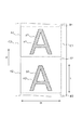
図7に、感光ドラム1の表面上において画像を形成することが可能な画像形成部と、この画像形成部における印画部と非印画部を説明するための模式図(概念図)を示す。図はに感光ドラム表面の回転方向(表面移動方向)Rにおける展開図である。
FIG. 7 is a schematic diagram (conceptual diagram) for explaining an image forming unit capable of forming an image on the surface of the
本実施例の画像形成装置Aでは反転現像方式を採用しているため、感光ドラム1において、トナー像が形成される印画部p1、p2(トナーが付着する部分)に露光を行っている。更に本実施例では、トナー像が形成されず、印画部の背景となる部分(非印画部n1,n2)にも露光を行っている。この非印画部n1,n2に対する露光によって、感光ドラム1を帯電した後の、非印画部n1,n2の電位を、バックグラウンド露光にて調整することができる。
Since the image forming apparatus A of the present embodiment employs the reversal development method, the
以下の説明においては区別のために、印画部p1、p2に対する露光を特に印画露光とよび、非印画部n1,n2に対する露光をバックグラウンド露光(背景露光、非印画露光)と呼ぶこととする。印画部p1と非印画部n1を合わせた領域がトナー像を形成可能な領域、すなわち画像を形成するための画像領域A1、A2である。同様に印画部p2と非印画部n1を合わせた領域が画像領域A2である。画像領域A1,A2は、印画露光もしくはバックグラウンド露光の何れかの露光がなされる露光領域でもある。 In the following description, for the sake of distinction, the exposure for the print portions p1 and p2 is particularly called print exposure, and the exposure for the non-print portions n1 and n2 is called background exposure (background exposure, non-print exposure). A region obtained by combining the print portion p1 and the non-print portion n1 is a region where a toner image can be formed, that is, image regions A1 and A2 for forming an image. Similarly, an area obtained by combining the printing part p2 and the non-printing part n1 is an image area A2. The image areas A1 and A2 are also exposure areas to be subjected to either a print exposure or a background exposure.
なお、画像領域と画像領域の間に挟まれることになる非画像領域B1、B2、B3はバックグラウンド露光される場合もあれば、バックグラウンド露光されない場合もある。画像形成装置Aの構成等によって適宜選択されるものである。本実施例では、非画像領域B1,B2、B3は露光されないものとする。つまり非画像領域B1、B2、B3は非露光領域とする。 Note that the non-image areas B1, B2, and B3 to be sandwiched between the image areas may be background-exposed or may not be background-exposed. It is appropriately selected depending on the configuration of the image forming apparatus A and the like. In this embodiment, it is assumed that the non-image areas B1, B2, and B3 are not exposed. That is, the non-image areas B1, B2, and B3 are non-exposed areas.
また記録媒体の幅によっては、画像領域A1の外側(幅方向Wの外側)の端部領域C1、C2も非画像領域となる。端部領域C1、C2も本実施理例では、露光せず非露光領域とした。しかし、端部領域C1、C2をバックグラウンド露光してもよい(端部領域C1、C2を露光領域に含めてもよい)。 Depending on the width of the recording medium, the end areas C1 and C2 outside the image area A1 (outside in the width direction W) are also non-image areas. In the present embodiment, the end regions C1 and C2 are not exposed but are non-exposed regions. However, the end regions C1 and C2 may be subjected to background exposure (the end regions C1 and C2 may be included in the exposure region).
トナー像を形成するときに印画露光する際は、1ドット(単位領域)あたり、少なくとも20μm以上の幅を露光している。これは、感光ドラム1上にトナーを現像するのに必要な潜像を形成するためには、少なくとも20μm以上の幅を露光する必要があるためである。
When printing exposure is performed when forming a toner image, a width of at least 20 μm or more per dot (unit area) is exposed. This is because it is necessary to expose at least a width of 20 μm or more in order to form a latent image necessary for developing the toner on the
一方で、バックグラウンド露光を行なう際には、4μmの幅で露光している。これによって、帯電ローラ2により帯電された感光ドラム1の表面電位を一定の量変化させている。しかし、バックグラウンド露光領域は、トナーによって現像されない(トナー像が形成されない)。
On the other hand, when performing background exposure, exposure is performed with a width of 4 μm. As a result, the surface potential of the
つまり、バックグラウンド露光による感光ドラム1の電位の変化量(絶対値の低下量)は、印画露光による変化量(絶対値の低下量)よりも少ない。そのためバックグラウンド露光した非印画部n1,n2には、現像ローラ5(図1参照)からトナーが転移せず、トナーが付着しない。
In other words, the amount of change in the potential of the
なお従来は、レーザの発光強度を印画露光よりも弱くした状態で、連続的に露光することでバックグラウンド露光を行っていた。これに対して本実施例では、露光においてレーザを断続的に発光させる方法を用いていることが特徴である。つまりバックグラウンド露光をする際、レーザ光量を弱くするのではなく、トナー像を形成するときの光量(印画露光と同じ光量)の状態でレーザを発光させつつ、発光時間を短くする(レーザによって露光する幅を短くする)。 Conventionally, background exposure has been performed by continuous exposure in a state where the laser emission intensity is weaker than that of print exposure. On the other hand, this embodiment is characterized in that a method of intermittently emitting a laser in exposure is used. In other words, when the background exposure is performed, the laser light is not weakened, but the light emission time is shortened while the laser light is emitted in the state of the light amount when forming the toner image (the same light amount as the print exposure). To reduce the width of
このようにバックグラウンド露光と印画露光で露光時間が異なる結果、スキャナユニットはバックグラウンド露光のために、感光ドラム1の1ドット(単位領域)毎に断続的に露光をすることになる。
As described above, as a result of the different exposure times between the background exposure and the print exposure, the scanner unit exposes intermittently for each dot (unit area) of the
従来のバックグラウンド露光方法では、バックグラウンド露光において印画露光よりも、光量を弱くする必要があった。そのためレーザ素子には、バックグラウンド露光用の弱い光量から、トナー像形成時に用いる印画露光用の強い光量までの広い光量出力範囲(光量可変域)が必要となっていた。さらに、その光量範囲全域において精度も求められることから、高価なレーザ素子を用いる必要があった。 In the conventional background exposure method, it is necessary to make the amount of light weaker in background exposure than in print exposure. Therefore, the laser element needs a wide light amount output range (light amount variable region) from a weak light amount for background exposure to a strong light amount for print exposure used at the time of toner image formation. Furthermore, since accuracy is also required over the entire light amount range, it is necessary to use an expensive laser element.
一方、本実施例では印画露光とバックグラウンド露光とでは、光量におおきな変化がないので、レーザ素子の光量可変域を限定することが可能となる。そのため比較的安価なレーザ素子を利用可能である。また、バックグラウンド露光でも強い光量で露光できる。感光ドラム1は一般に強い光量に対する感度特性の方が、弱い光量に対する感度特性より安定している。その観点でも本実施例の構成は利点がある。
On the other hand, in this embodiment, since there is no significant change in the light amount between the print exposure and the background exposure, it is possible to limit the light amount variable range of the laser element. Therefore, a relatively inexpensive laser element can be used. Moreover, it can expose with a strong light quantity even in background exposure. In general, the
<トナー使用量検知>
本実施例では、トナー使用量を検知するためにレーザドライバ31に入力されるビデオ信号をカウント手段34によって計測している。図1にあるように、ビデオコントローラ33とレーザドライバ31の間にカウント手段34を設け、レーザドライバ31に入力される信号を直接検知している。この方法にすることで、トナー消費に関係するレーザの発光を直接カウントすることができる。感光ドラム1に対してレーザ素子が発光すると、露光された感光ドラム1の領域に現像ローラ5からトナーが転移し、現像装置8に収容されたトナーが消費されることになる。レーザの発光を検知できれば、トナーの消費量(利用量)がわかり、その結果、現像装置8に収容されるトナーの残量もわかる。
<Toner usage detection>
In this embodiment, the video signal input to the
従来のホストPC100から送られてくる画像情報からトナー使用量を算出する方法では、画像形成装置本体Aで制御している定期的なトナー吐き出し動作や濃度検知制御などによるトナー使用量を検知することが困難であった。つまり、画像形成装置AはホストPC100から画像形成を指示された場合でなくても、キャリブレーション時等にトナーを消費することがある。しかしホストPC100から受ける画像情報からはそのようなトナー消費を検知できなかった。
In the conventional method of calculating the toner usage amount from the image information sent from the
この課題に対して、本実施例では、レーザドライバ31に入力されるビデオ信号(露光を指示する電気信号)をカウント手段34がカウントする。ホストPCからの指示による画像形成以外であっても、レーザの発光を確実に検知することができるため、その発光によって消費されるトナーの使用量も精度よく検知することが可能となる。
In response to this problem, in this embodiment, the counting means 34 counts the video signal (electric signal instructing exposure) input to the
カウント手段34は、ビデオコントローラ33から入力されたビデオ信号がONのときに計測し、その数を積算していく。
The counting means 34 measures when the video signal input from the
ただし、上記のように、レーザドライバ31に入るビデオ信号を直接検知する方法では、上記したバックグラウンド露光でレーザを発光させるビデオ信号も検知することになる。バックグラウンド露光がなされても、トナーは消費されない。バックグラウンド露光を指示するビデオ信号もカウントして、そのカウント値をトナー使用量の算出に利用してしまうと、ビデオ信号に基づいて算出されるトナー消費量が実際のトナー消費量と異なってしまう可能性がある。
However, as described above, in the method of directly detecting the video signal entering the
そのため、本実施例では以下に説明する方法でトナー使用量を算出することとしている。まず印画露光を指示するビデオ信号を第1信号とし、バックグラウンド露光を指示するビデオ信号を第2信号とする。そして本実施例では、カウント手段34が第1信号および第2信号の両方をカウントしつつ、カウントされたカウント値から、第1信号のみのカウント値を演算で求める演算手段を備えたことを特徴とする。 Therefore, in this embodiment, the toner usage is calculated by the method described below. First, a video signal instructing print exposure is a first signal, and a video signal instructing background exposure is a second signal. In this embodiment, the counting means 34 is provided with calculation means for calculating both the first signal and the second signal and calculating the count value of only the first signal from the counted value. And
本実施例のバックグラウンド露光は1ドットの10%の幅で露光し、トナー像形成時の印画露光は1ドットの50%以上の幅で露光している。カウント手段34は1ドット内をランダムなタイミングでサンプリングを行ない、ビデオ信号がONであるか否かを判断する。つまりカウント手段34はドットごとにサンプリング(カウント)を行うタイミングが異なる。 In this embodiment, the background exposure is performed with a width of 10% of one dot, and the printing exposure at the time of toner image formation is performed with a width of 50% or more of one dot. The counting means 34 samples within one dot at random timing and determines whether or not the video signal is ON. That is, the counting means 34 has a different sampling (counting) timing for each dot.
カウント手段34のサンプリング時間はバックグラウンド露光の発光時間よりも短く、カウント手段34の検知状態がHighのときにビデオ信号がON状態になっていればカウントを行う。 The sampling time of the counting means 34 is shorter than the light emission time of the background exposure. If the video signal is in the ON state when the detection state of the counting means 34 is High, the counting is performed.
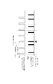
図2は1ドットの10%の幅でバックグラウンド露光を全ての露光領域(画像領域A1とA2のこと:図7参照)で行った場合に、カウント手段34が行うサンプリングを表したものである。7ドットのうち1ドットの発光が、カウント手段34にカウントされている。カウント手段34のサンプリングがランダムなタイミングで行われることにより、バックグラウンド露光されたドットの一部が発光しているドットとしてカウントされることになる。 FIG. 2 shows sampling performed by the counting means 34 when background exposure is performed in all exposure areas (refer to FIG. 7) with a 10% width of one dot. . One dot of the seven dots is counted by the counting means 34. Since the sampling of the counting means 34 is performed at random timing, a part of the dots subjected to background exposure are counted as light emitting dots.
印画画像の全ドットをサンプリングするなど、十分な数のサンプリングが行われる場合においては、バックグラウンド露光による発光がカウント手段34にカウントされる割合は、1ドットにおいてバックグラウンド露光による露光幅が占める割合に比例する。したがって、本実施例のように1ドットの10%幅でバックグラウンド露光している場合においては、非印画ドットの内の10%のドットが発光したものとしてカウント手段34にカウントされることになる。 In the case where a sufficient number of samplings are performed, such as sampling all dots of a print image, the ratio at which light emission by background exposure is counted by the counting means 34 is the ratio that the exposure width by background exposure occupies in one dot Is proportional to Therefore, when the background exposure is performed with 10% width of 1 dot as in this embodiment, 10% of the non-printing dots are counted by the counting means 34 as being emitted. .
つまりバックグラウンド露光(第2信号)がカウント手段34にカウントされる割合は、印画露光(第1信号)がカウントされる割合よりも小さいものの、一定の割合(約10パーセント)でかならずカウントされることになる。 That is, the ratio at which the background exposure (second signal) is counted by the counting means 34 is smaller than the ratio at which the print exposure (first signal) is counted, but is always counted at a constant ratio (about 10 percent). It will be.
実際にトナー像形成を行った場合は図3に示すように、バックグラウンド露光のためのビデオ信号(第2信号)と、トナー像形成時のビデオ信号(印画露光用の第1信号)が重なった最終ビデオ信号(電気信号)をカウントすることになる。カウント手段34はトナーが消費されていない露光分(第2信号による露光分)もまとめてカウントしてしまうことになる。 When the toner image is actually formed, as shown in FIG. 3, the video signal for background exposure (second signal) and the video signal at the time of toner image formation (first signal for print exposure) overlap. The final video signal (electrical signal) is counted. The counting means 34 also counts the amount of exposure for which toner is not consumed (exposure for the second signal).
例えば図3では、7ドット中、印画露光領域(p1、p2)となるドットが4ドットある(左から1、4,5,7ドット目)。バックグラウンド露光領域(n1,n2)となるドットが3ドットある(左から2,3,6ドット目)。そして、カウント手段34は、全ての印画領域に加えて、非印画領域である左から7ドット目もカウントしているので、カウント数は5ドット分となる。つまり印画露光領域に相当するカウント数(4ドット分)よりも多くカウント手段34はカウントしてしまっている。 For example, in FIG. 3, there are 4 dots (7th, 1st, 4th, 5th, and 7th dots from the left) that become print exposure areas (p1, p2) in 7 dots. There are 3 dots to be the background exposure area (n1, n2) (second, third and sixth dots from the left). The counting means 34 counts the seventh dot from the left, which is a non-printing area, in addition to all the printing areas, so the count number is 5 dots. That is, the counting means 34 counts more than the count number (4 dots) corresponding to the print exposure area.
上記課題を解決するため、カウント手段34がカウントした値からバックグラウンド露光分のカウント値(第2信号のカウント値)の影響を除いて、トナー像形成を行った露光のカウント値(第1信号のカウント値)だけ取り出す方法について説明する。 In order to solve the above problems, the count value of the exposure (first signal) in which the toner image is formed by removing the influence of the count value of the background exposure (count value of the second signal) from the value counted by the counting means 34. Will be described.
トナー像形成を行った露光カウント(印画露光を指示する第1信号をカウントした値)をXとする。そして、カウント手段34が実際にカウントするカウント値をY(第1信号をカウントした値と第2信号をカウントした値を足し合わせた値)とする。 Let X be the exposure count at which the toner image is formed (the value obtained by counting the first signal instructing print exposure). The count value actually counted by the counting means 34 is Y (the value obtained by adding the value obtained by counting the first signal and the value obtained by counting the second signal).
また、露光領域(A1、A2)の全てを印画露光した場合にカウント手段34がカウントする値をZ、露光領域(A1、A2)の全てをバックグラウンド露光した場合にカウント手段34がカウントする値をBGとする。 Further, the value counted by the counting means 34 when the exposure exposure (A1, A2) is all subjected to the print exposure is Z, and the value counted by the counting means 34 when the exposure exposure (A1, A2) is all exposed in the background. Is BG.
ここで求めたい値X(印画露光を指示する第1信号のみのカウント値)は、Y(第1信号と第2信号の両方を含んだカウント値)からバックグラウンド露光によってカウント手段34がカウントする値(第2信号のカウント値)を引いたものである。そのため以下の式であらわすことができる。 The value X to be obtained here (the count value of only the first signal instructing the print exposure) is counted by the counting means 34 by the background exposure from Y (the count value including both the first signal and the second signal). The value (count value of the second signal) is subtracted. Therefore, it can be expressed by the following formula.
X=Y−BG・(Z−X)/Z (式1)
この式をXだけの形であらわすと
X=Z・(Y−BG)/(Z−BG) (式2)
となる。
X = Y−BG · (Z−X) / Z (Formula 1)
When this equation is expressed in the form of X only, X = Z · (Y−BG) / (Z−BG) (Equation 2)
It becomes.
X:印画露光(第1信号による露光)のカウントに相当するカウント値(後述する演算手段(CPU35)が求めるカウント値)
Y:カウント手段34が実際にカウントしたカウント値(第1信号および第2信号のカウントが含まれるカウント値)
Z:露光領域がすべて印画部であった場合にカウント手段34がカウントするカウント値(露光領域の全てを第1信号のみによって露光した場合のカウントに相当するカウント値。既知の値)
BG:露光領域がすべて非印画部であった場合にカウント手段34がカウントするカウント値(露光領域の全てを第2信号のみによって露光した場合のカウントに相当するカウント値。既知の値)
ZとBGは露光領域(A1、A2)の大きさできまる値である。つまり画像領域の大きさを決める用紙サイズ(図7に示す幅Wや長さL)によって決まる値なので、あらかじめ用紙サイズごとの値を記憶しておけばよい。上記式(2)を用いることで、トナー像形成を行った露光のカウントだけ取り出すことが可能になる。
X: Count value corresponding to the count of print exposure (exposure by the first signal) (a count value obtained by a calculation means (CPU 35) described later)
Y: Count value actually counted by the counting means 34 (count value including the counts of the first signal and the second signal)
Z: a count value counted by the counting means 34 when all the exposure areas are print portions (a count value corresponding to a count when all the exposure areas are exposed only by the first signal; known value)
BG: a count value counted by the counting means 34 when all the exposure areas are non-printed portions (a count value corresponding to a count when all the exposure areas are exposed only by the second signal; a known value)
Z and BG are values that can be determined by the size of the exposure area (A1, A2). That is, since the value is determined by the paper size (width W or length L shown in FIG. 7) that determines the size of the image area, the value for each paper size may be stored in advance. By using the above formula (2), it is possible to take out only the exposure count at which the toner image is formed.
なお、式(1)の導出方法について、以下に説明する。 In addition, the derivation method of Formula (1) is demonstrated below.
第1信号に起因するカウント値は、印画露光がされる領域の面積に比例する。そして、露光領域(A1、A2)のすべてを印画露光した分のカウント値がZであり、露光領域(A1、A2)のうち印画部p1、p2のみに印画露光した分のみのカウント値がXである。 The count value resulting from the first signal is proportional to the area of the region where the print exposure is performed. The count value corresponding to the print exposure of all the exposure areas (A1, A2) is Z, and the count value corresponding to the print exposure of only the print portions p1, p2 in the exposure area (A1, A2) is X. It is.
露光領域(すなわち画像領域A1、A2)と、印画露光がされた印画露光領域(すなわち印画部p1、p2)との面積比は、ZとXを用いて、以下のように表せる。 The area ratio between the exposure area (that is, the image areas A1 and A2) and the print exposure area that has undergone the print exposure (that is, the print portions p1 and p2) can be expressed as follows using Z and X.
露光領域(A1、A2):印画露光領域(印画部p1、p2)=Z:X
そして、露光領域(A1、A2)から、印画露光領域(p1、p2)を除いた部分が、バックグラウンド露光がされるバックグラウンド露光領域である。このバックグラウンド領域は非印画部n1,n2に相当する(図7参照)。露光領域(A1、A2)と、バックグラウンド露光領域(非印画部n1,n2)の面積比は、以下のようになる。
Exposure area (A1, A2): Print exposure area (print portions p1, p2) = Z: X
A portion of the exposure area (A1, A2) excluding the print exposure area (p1, p2) is a background exposure area where background exposure is performed. This background area corresponds to the non-printed portions n1 and n2 (see FIG. 7). The area ratio between the exposure region (A1, A2) and the background exposure region (non-printed portions n1, n2) is as follows.
露光領域(A1、A2):バックグラウンド露光領域(非印画部n1,n2)
=Z:Z−X
つまりバックグラウンド露光されるバックグラウンド露光領域(非印画部n1,n2)の面積は、印画露光とバックグラウンド露光のいずれかがされる全ての露光領域(A1、A2)の面積に対して、(Z−X)/Zの割合を占める。
Exposure area (A1, A2): Background exposure area (non-printed parts n1, n2)
= Z: Z-X
That is, the area of the background exposure area (non-printed portions n1 and n2) subjected to background exposure is equal to the area of all exposure areas (A1, A2) subjected to either print exposure or background exposure. Z-X) / Z.
そして、露光領域(A1、A2)の全域をバックグラウンド露光した場合のカウント値がBGである。そのため露光領域(A1、A2)の(Z−X)/Zをバックグラウンド露光した場合には、バックグラウンド露光によるカウント値Aは、以下のようになる。 The count value when the entire exposure area (A1, A2) is subjected to background exposure is BG. Therefore, when (Z−X) / Z in the exposure areas (A1, A2) is subjected to background exposure, the count value A by background exposure is as follows.
A=BG・(Z−X)/Z (式3)
A:バックグラウンド露光(第2信号による露光)のカウントに相当するカウント値
カウント手段34が実際にカウントするカウント値Yは、トナー像を形成するための印画露光に起因するカウント値Xと、トナー像を形成しないバックグラウンド露光に起因するカウント値Aを足し合わせたものである。したがって、
Y=X+A
である。この式を変形すると、以下のような計算によって、式1が求まる。
A = BG · (Z−X) / Z (Formula 3)
A: Count value corresponding to the count of background exposure (exposure by the second signal) The count value Y actually counted by the counting means 34 is the count value X resulting from the print exposure for forming the toner image, and the toner. The count value A resulting from background exposure that does not form an image is added. Therefore,
Y = X + A
It is. When this equation is transformed,
X=Y−A=Y−BG・(Z−X)/Z (式1):再掲
そして、この式(1)を更に変形してXを求める式としたのが式2である。
X = Y−A = Y−BG · (Z−X) / Z (Formula 1): Reprinted Then,
X=Z・(Y−BG)/(Z−BG) (式2):再掲
つまり式2に基づいて、演算手段であるCPU35(図1)が、印画露光(第1信号による露光)によるカウント値Xを求めるものである。なお式2を見るとわかるように、CPU35が求めるカウント値Xは、カウント値Yを変数とした一次関数で求められる。
X = Z · (Y−BG) / (Z−BG) (Formula 2): Reprinting In other words, based on
つまり式2を変形すると以下のようになる。
In other words, the
X=DY−E (式4)
ただし
D=Z/(Z−BG)>0
E=Z・BG/(Z−BG)>0
である。
X = DY-E (Formula 4)
However, D = Z / (Z-BG)> 0
E = Z · BG / (Z-BG)> 0
It is.
以下に、例として、レターサイズ(215.9mm×279.4mm)の用紙に5%の印画率(印字率)の画像を印刷する場合について記述する。600dpiの解像度においてレターサイズの全ドット数は33660000ドットなので、Z=33660000となり、BGはZの10%に相当するので、BG=3366000となる。5%印画をした場合1683000ドットが像形成に使われるドットであり、残りの31977000ドットにバックグラウンド露光が行われる。したがって
Y=1683000+31977000×0.1=4880700
となる。これを前述の式2に当てはめると
X=1683000
と求めることができ、バックグラウンド露光の影響を除いた、印画露光に相当するカウント値を求めることができる。
Hereinafter, as an example, a case where an image having a printing rate (printing rate) of 5% is printed on a letter size (215.9 mm × 279.4 mm) sheet will be described. Since the total number of letter-size dots at a resolution of 600 dpi is 33660000 dots, Z = 3366600, and BG corresponds to 10% of Z, so BG = 3366000. In the case of 5% printing, 1683000 dots are used for image formation, and background exposure is performed on the remaining 31977000 dots. Therefore Y = 1683000 + 31977000 × 0.1 = 4880700
It becomes. Applying this to
The count value corresponding to the print exposure can be obtained without the influence of the background exposure.
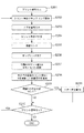
次に、画像形成時のトナー使用量検知の具体的なフローについて、図4に基づいて説明する。プリント信号が入力されると(S201)、カウント手段34がサンプリングを開始する(S202)。カウント手段34は、ビデオコントローラ33からレーザドライバ31に入力されるビデオ信号を計測する(S203、S204)。カウント手段34は、画像エンドの情報を受けると(S205)、サンプリングを終了する(S206)。
Next, a specific flow of toner usage detection at the time of image formation will be described with reference to FIG. When the print signal is input (S201), the
カウント手段34が計測(カウント)した値Yから式2(式4)を用いて、演算手段であるCPU35はXを算出し、画像イメージ1枚毎に集計する。そして、CPU35はXを、画像形成装置本体に搭載されたメモリ36に一旦、記憶する(S207)。プロセスカートリッジに搭載された不揮発メモリ26には、それまでに蓄積されたビデオカウントの積算値Vと、予め定められたビデオカウントの閾値Tが格納されている。閾値Tは白抜け画像等の画像不良が発生しないトナー残量により予め設定された値であり、事前にCPU35を介して読み出され、メモリ36に保持されている。CPU35は、蓄積されたカウント値Vに、今回の画像形成でカウントされた値Xを足した積算値Wを算出する(S208)。この積算値Wが、トナーの使用量に対応する値である。
Based on the value Y measured (counted) by the counting means 34, the
その積算値Wと予め定められた閾値Tとを比較して(S209)、閾値Tを超えている時(S209−Yes)には画像形成装置に予め備えられた表示部37を介して、トナー無を報知する(S211)。閾値を超えていない時(S209−No)は、プリント信号があれば(S210−Yes)、再度、同じプロセスを実施する。プリント信号がなければ終了し(S210−No)、積算値Wと閾値Tの値から見積もったトナーの残量を、表示部37を介して報知する。
The integrated value W is compared with a predetermined threshold value T (S209). When the threshold value T is exceeded (S209-Yes), the toner is passed through the
このようにして、画像形成装置AのCUP35はトナー使用量を検知し、トナー有無を判断している。そしてトCUP35はナー使用量に関する情報(トナー残量)を報知している。
In this way, the
最後に上記で説明した本実施例の特徴をまとめる。 Finally, the features of the present embodiment described above are summarized.
カウント手段34がビデオ信号をカウントしたカウント値Yは、第1信号(印画露光用の信号)のカウント値Xだけでなく、第2信号(バックグラウンド露光用の信号)のカウント値Aも含めた値である。 The count value Y obtained by the counting means 34 counting the video signal includes not only the count value X of the first signal (print exposure signal) but also the count value A of the second signal (background exposure signal). Value.
つまり発光がカウント手段34にカウントされる確率は、1ドットあたりにおいて、電気信号が発光を指示している時間(ONになっている時間)の長さに比例する。第2信号のON時間は、第1信号のON時間よりも短く、第2信号がカウントされる割合(確率)は、第1信号がカウントされる割合(確率)よりも小さい。しかしながら、サンプリング数を十分に大きくした場合には、第2信号も一定の割合でカウントされることになる。 That is, the probability that the light emission is counted by the counting means 34 is proportional to the length of time that the electrical signal instructs the light emission (the time when it is ON) per dot. The ON time of the second signal is shorter than the ON time of the first signal, and the rate (probability) at which the second signal is counted is smaller than the rate (probability) at which the first signal is counted. However, when the number of samplings is made sufficiently large, the second signal is also counted at a certain rate.
そのためトナー消費量を求めるためには、カウント値Yから、カウント値Xを求める必要がある。 Therefore, in order to obtain the toner consumption amount, it is necessary to obtain the count value X from the count value Y.
そこで、本実施例では、第1信号のカウントに相当するカウント値Xを、式2(式4)に基づきカウント値Yから求めている。カウント値Xは、カウント値Yを変数とする一次関数として求まるものである。 Therefore, in this embodiment, the count value X corresponding to the count of the first signal is obtained from the count value Y based on Expression 2 (Expression 4). The count value X is obtained as a linear function with the count value Y as a variable.
そしてカウント値Xは、トナー消費量にも対応する値である。したがって、CPU35はカウント値Xからトナー消費量を検出(算出)可能である。またあらかじめ現像装置8のトナー収容室に収容されていたトナー量が、メモリ26等に記憶されていれば、トナー残量を検出(算出)することも可能である。
The count value X is also a value corresponding to the toner consumption. Therefore, the
以上のような制御を行うことにより、背景部(非印画部)に対してバックグラウンド露光を行った場合においても、画像形成装置Aは現像装置8やプロセスカートリッジBが、残りどれだけ使用できるかより正確に判断することができる。
By performing the control as described above, the remaining amount of the developing
たとえば、画像領域の全てをバックグラウンド露光して連続して画像形成動作を行った場合、つまり印画を行わない画像(記録媒体の全面が白くなる全白画像)を連続して形成した場合、トナー消費はほぼ0である。その一方、カウント手段は、第2信号(バックグラウンド露光用の信号)をカウントすることになる。しかしながら、本実施例では、カウント手段によるカウント値Yから、バックグラウンド露光用の信号の影響(カウント値Aの影響)を除いたカウンタ値XをCUP35が求めている。すなわちCPU35がカウンタ値Xから算出するトナー使用量は0のままであり、画像形成を繰り返したとしても画像形成装置Aは使用量の増加や、トナー残量の低下を報知することはない。報知される使用量や残量は変化しない。
For example, when the entire image area is subjected to background exposure and an image forming operation is continuously performed, that is, when an image that is not printed (an all-white image in which the entire surface of the recording medium is white) is continuously formed, toner Consumption is almost zero. On the other hand, the counting means counts the second signal (background exposure signal). However, in this embodiment, the
そのため報知手段としてのCPU35は、表示部37やホストPC100に、トナー使用量(トナー残量)をより正確に報知できる。
Therefore, the
あるいはトナー使用量に応じて、画像形成時の各種条件(現像ローラに印加する電圧値など)を適宜変更することも容易となる。 Alternatively, various conditions during image formation (such as a voltage value applied to the developing roller) can be easily changed according to the amount of toner used.
なお本実施例では図7に示す非画像領域B1、B2,B3や端部領域C1、C2はバックグラウンド露光しなかった。しかし非画像領域B1、B2,B3や端部領域C1、C2もバックグラウンド露光するのであれば、A1,A2、B1、B2,B3、C1,C2を露光領域とすればよい。そして露光領域となる領域A1,A2、B1、B2,B3、C1,C2に基づいて、式1におけるZやBG(すなわち式4におけるDやE)を定めておけば、本実施例同様にトナー使用量を検知可能である。すなわち露光領域の大きさにあわせて、ZやBG(DやE)を定めておけば、トナー使用量(トナー残量)を検知可能である。 In this embodiment, the non-image areas B1, B2, B3 and the end areas C1, C2 shown in FIG. 7 were not subjected to background exposure. However, if the non-image areas B1, B2, B3 and the end areas C1, C2 are also subjected to background exposure, the exposure areas may be A1, A2, B1, B2, B3, C1, C2. Then, if Z and BG in Formula 1 (that is, D and E in Formula 4) are determined based on the exposure areas A1, A2, B1, B2, B3, C1, and C2, the toner is the same as in this embodiment. The amount used can be detected. That is, if Z or BG (D or E) is determined in accordance with the size of the exposure area, the toner usage (toner remaining amount) can be detected.
露光領域の大きさ(バックグラウンド露光の条件)に適合するZやBGの値(すなわちDやEの値)をメモリ36やメモリ26(図1参照)等にあらかじめ記憶しておけばよい。
Z and BG values (that is, D and E values) that match the size of the exposure area (background exposure conditions) may be stored in advance in the
(実施例2)
次にプロセスカートリッジの使用状況に応じて、バックグラウンド露光の露光幅を可変させる構成について説明する。基本的な構成(画像形成装置全体構成や画像形成プロセスの概要)は実施例1と同一なので、説明は省略し、異なる点について説明する。
(Example 2)
Next, a configuration for changing the exposure width of the background exposure according to the use status of the process cartridge will be described. Since the basic configuration (the overall configuration of the image forming apparatus and the outline of the image forming process) is the same as that of the first embodiment, the description thereof will be omitted, and different points will be described.
<露光動作について>
本実施例の構成では、不図示の電源ユニットから帯電ローラ2には−1000V、現像ローラ5には−400Vで固定された電圧が印加されている。この電圧値で固定することで、電気部品を最小限にすることが可能となり、電源ユニットの小型化が可能となっている。
<About exposure operation>
In the configuration of this embodiment, a fixed voltage of −1000 V is applied to the charging
実施例1の構成とは異なり、使用環境が変化した際にも、感光ドラム1の表面電位を一定に保つために、1ドットあたりの、バックグラウンド露光の露光幅を変える制御を行う。つまり画像形成装置Aが使用される環境に応じて、1ドット(単位領域)あたりをバックグラウンド露光(第2信号による露光)が露光する露光時間を変えるようにしている。
Unlike the configuration of the first embodiment, in order to keep the surface potential of the
例えば、実施例1ではバックグラウンド露光幅は1ドットの10パーセント程度(4μm)で固定であったが、本実施例では環境の絶対水分量(絶対湿度)が高くなるにしたがって4μmよりもよりも長い幅をバックグラウンド露光する。言い換えると、絶対水分量が高くなるにしたがって、第2信号による単位領域当たりの露光時間が長くする。 For example, in Example 1, the background exposure width was fixed at about 10 percent (4 μm) of one dot, but in this example, as the absolute water content (absolute humidity) of the environment increases, the background exposure width becomes more than 4 μm. Long background exposure. In other words, the exposure time per unit area by the second signal is increased as the absolute water content increases.
使用環境の検知は画像形成装置の装置本体が備える環境センサにより行われ、環境センサが測定した絶対水分量に応じてバックグラウンド露光の露光幅を変える制御を行う。本実施例においては図5に示すように、5つのゾーンに分けられた環境テーブルを持ち、そのゾーンに対応するバックグラウンド露光幅が設定されている。このような制御を行うことで、環境によって帯電ローラ2により帯電された後の感光ドラム1の表面電位を一定にすることが可能になる。本実施例においては環境をゾーンで分けているが、詳細な制御を行う必要がある場合には絶対水分量の値から計算してもよい。また環境制御に用いるパラメータは絶対水分量でなく温度または湿度(相対湿度)で行っても良い。
The detection of the usage environment is performed by an environmental sensor provided in the main body of the image forming apparatus, and control is performed to change the exposure width of background exposure according to the absolute water content measured by the environmental sensor. In this embodiment, as shown in FIG. 5, the environment table is divided into five zones, and the background exposure width corresponding to the zone is set. By performing such control, the surface potential of the
本実施例では、湿度(相対湿度や絶対湿度であらわされる空気中の水分量)が高くなるほど、BGを大きくする(D,Eを大きくする)。しかしこれに限るものではなく画像形成装置Aの構成にあわせて種々の応用が可能である。 In the present embodiment, the BG is increased (D and E are increased) as the humidity (the amount of moisture in the air expressed by relative humidity or absolute humidity) increases. However, the present invention is not limited to this, and various applications are possible according to the configuration of the image forming apparatus A.
<トナー使用量検知>
実施例1との違いについてのみ記載する。本実施例の構成においては使用環境により、バックグラウンド露光の露光幅を可変させている。したがって、露光領域の全てを印画露光した場合や露光領域の全てをバックグラウンド露光した場合にカウント手段34がカウントする値(前述のBG)が使用環境で変わることになる。環境によって区分される5つのゾーンごとにあらかじめBGの値を設定する。
<Toner usage detection>
Only differences from Example 1 will be described. In the configuration of the present embodiment, the exposure width of the background exposure is varied depending on the use environment. Accordingly, the value (BG described above) counted by the
図6はその一例として、レターサイズの画像形成を行う場合のBGの値をそれぞれの環境ゾーンにおいて設定したものである。これらのBGを用いて式2において、使用環境に応じてXの算出が行われる。同様に式4においては、使用環境が変わればBGから求まる定数Dや定数Eを異なる値にしてXを求める。
FIG. 6 shows an example in which BG values for letter-size image formation are set in each environment zone. Using these BGs, X is calculated in
これ以降のトナー使用量検知フローは実施例1と同じなので説明を省略する。 Since the subsequent toner usage amount detection flow is the same as that in the first embodiment, a description thereof will be omitted.
(実施例3)
本実施例ではカウント手段34によるカウントのタイミングを実施例1とは異ならせた構成について説明する。
(Example 3)
In this embodiment, a configuration in which the timing of counting by the counting means 34 is different from that in the first embodiment will be described.
実施例1では、カウント手段34がカウントするタイミングがランダムであったが略1ドットあたり1回のタイミングでサンプリングが行われていた(図3参照)。
In the first embodiment, the timing of counting by the
これに対して、本実施例では図8に示すようにカウント手段34がカウントするタイミングが周期的である一方で、カウントするタイミングが1ドット1回よりも遅いペースである。図8では、約1、2ドットあたり1回のペースでカウント手段34はカウントしている。 In contrast, in this embodiment, as shown in FIG. 8, the counting timing of the counting means 34 is periodic, while the counting timing is slower than one dot once. In FIG. 8, the counting means 34 counts at a pace of about once every 1 or 2 dots.
ビデオ信号の周期(1ドットあたり1回の周期)はごく短い時間である。そのためカウント手段34の性能によっては、ビデオ信号の周期に間に合うようにカウントできない。この場合には、図8のように、ビデオ信号の周期(発光の周期)よりもカウント手段34のカウント周期が長くなる。 The cycle of the video signal (one cycle per dot) is a very short time. Therefore, depending on the performance of the counting means 34, it cannot be counted in time for the period of the video signal. In this case, as shown in FIG. 8, the count cycle of the counting means 34 becomes longer than the cycle of the video signal (light emission cycle).
この場合カウント手段34が全くカウントしないドットが生じることになる(図8においては左から2ドット目)。しかし、カウント手段34がカウントできないドットがある場合であっても、カウント手段34によるサンプリング数が十分に大きいのであれば、カウント手段によるカウント値Y(実施例1の式(1)参照)は、実際に露光に対応した値となる。 In this case, a dot which is not counted at all by the counting means 34 is generated (second dot from the left in FIG. 8). However, even if there are dots that cannot be counted by the counting means 34, if the sampling number by the counting means 34 is sufficiently large, the count value Y by the counting means (see equation (1) of the first embodiment) is The value actually corresponds to exposure.
つまりサンプリング数が十分に大きければ、一定の割合でカウントしないドットが含まれていたとしても(サンプリングされるドットが一部だとしても)、統計的にほぼ正確なカウント値を得られる。 That is, if the number of samplings is sufficiently large, a statistically almost accurate count value can be obtained even if dots that are not counted at a certain rate are included (even if some of the dots are sampled).
つまり本実施例の構成にかぎらずカウント手段34は、統計的に必要とされる程度のドットをカウントすればよい。 In other words, the count means 34 may count dots that are statistically required, regardless of the configuration of the present embodiment.
また本実施例においてもそれぞれのドットにおいて、カウント手段34がビデオ信号をカウントするタイミングが異なり、一定の割合でバックグラウンド露光のための第2信号をカウントしてしまう。しかし本実施例でも式2(式4)に基づいて、第1信号(印画露光用の信号)のカウントに相当するカウント値Xを求めることが可能となる。本実施例で求められるカウント値Xも、統計的に第1信号のカウントに十分に対応した値とすることができる。 Also in this embodiment, the timing at which the counting means 34 counts the video signal is different for each dot, and the second signal for background exposure is counted at a constant rate. However, also in this embodiment, it is possible to obtain the count value X corresponding to the count of the first signal (print exposure signal) based on Expression 2 (Expression 4). The count value X obtained in the present embodiment can also be a value that sufficiently corresponds to the count of the first signal statistically.
1 感光ドラム
2 帯電ローラ
8 現像装置
9 トナー収納容室
30 スキャナユニット
33 ビデオコントローラ
34 カウント手段
35 CPU
A 画像形成装置
DESCRIPTION OF
A Image forming apparatus
Claims (12)
前記像担持体を帯電する帯電手段と、
前記帯電手段で帯電された前記像担持体を露光することで静電潜像を形成する露光手段であって、像担持体の単位領域ごとに断続的な光の照射を行う露光手段と、
現像剤を収容する現像剤収容部を有し、前記静電潜像を現像剤によって現像する現像手段と、
前記露光手段に露光を指示する画像データに対応した電気信号を出力する信号出力部であって、現像剤像が形成される像担持体の印画部を露光させる第1信号と、現像剤像が形成されない像担持体の非印画部を露光する第2信号と、を出力する信号出力部と、を有し、
前記第2信号に基づく前記像担持体の単位領域あたりの露光時間が、前記第1信号に基づく前記像担持体の単位領域あたりの露光時間よりも短い画像形成装置であって、前記信号出力部から出力された電気信号が入力され、所定のタイミングでサンプリングを行って前記第1信号および前記第2信号をカウントし、前記第1信号のカウント値及び前記第2信号のカウント値を含むカウント値Yを出力するカウント手段と、
前記露光手段が露光する前記像担持体の露光領域の全てを前記第1信号のみによって露光した場合に前記カウント手段がカウントするカウント値をカウント値Z、前記露光領域の全てを前記第2信号のみによって露光した場合に前記カウント手段がカウントするカウント値をカウント値BGとした際に、前記カウント手段がカウントした前記カウント値Y、前記カウント値Z、及び、前記カウント値BGに基いて前記現像手段による現像剤の使用量に対応するカウント値を求める演算を行う演算手段と、
を備えることを特徴とする画像形成装置。 An image carrier;
Charging means for charging the image carrier;
An exposure unit that forms an electrostatic latent image by exposing the image carrier charged by the charging unit, the exposure unit performing intermittent light irradiation for each unit region of the image carrier;
A developer containing a developer containing portion, and developing means for developing the electrostatic latent image with a developer;
A signal output unit that outputs an electrical signal corresponding to image data instructing exposure to the exposure unit, the first signal for exposing the printing unit of the image carrier on which the developer image is formed, and the developer image A signal output unit that outputs a second signal for exposing a non-printing part of the image carrier that is not formed, and
An image forming apparatus in which an exposure time per unit area of the image carrier based on the second signal is shorter than an exposure time per unit area of the image carrier based on the first signal, the signal output unit The electric signal output from the signal is input , sampling is performed at a predetermined timing to count the first signal and the second signal, and the count value includes the count value of the first signal and the count value of the second signal Counting means for outputting Y ;
When all the exposure areas of the image carrier exposed by the exposure means are exposed only by the first signal, the count value counted by the counting means is a count value Z, and all the exposure areas are only the second signal. When the count value counted by the counting means when the exposure is performed is set to the count value BG, the developing means is based on the count value Y, the count value Z, and the count value BG counted by the counting means. Calculating means for calculating a count value corresponding to the amount of developer used by
An image forming apparatus comprising:
前記演算手段は、前記使用環境に応じて前記一次関数で用いられる定数の値を変更することを特徴とする請求項4に記載の画像形成装置。 Depending on the usage environment of the image forming apparatus, the exposure time for the second signal to expose the unit area is changed,
The image forming apparatus according to claim 4, wherein the calculation unit changes a value of a constant used in the linear function according to the use environment.
前記一次関数は、X=DY−E(D>0、E>0)と表すことができ、
前記使用環境における空気中の水分量が大きくなるほど、前記Dおよび前記Eも大きくすることを特徴とする請求項5に記載の画像形成装置。 The count value corresponding to the count value of the first signal and the X,
The linear function can be expressed as X = DY−E (D> 0, E> 0),
The image forming apparatus according to claim 5, wherein the D and the E are increased as the moisture content in the air in the use environment increases.
X=Z・(Y−BG)/(Z−BG)
X:前記演算手段が求めるカウント値 5. The image forming apparatus according to claim 3, wherein the calculation unit obtains a count value corresponding to the count value of the first signal from the count value Y counted by the counting unit by the following expression. apparatus.
X = Z · (Y-BG) / (Z-BG)
X: Count value obtained by the calculation means
前記演算手段は、前記使用環境に応じて前記BGとして異なる値を使用することを特徴とする請求項7に記載の画像形成装置。 Depending on the usage environment of the image forming apparatus, the exposure time for the second signal to expose the unit area is changed,
The image forming apparatus according to claim 7, wherein the calculation unit uses a different value as the BG according to the use environment.
前記演算手段により求められた現像剤の使用量、もしくは前記使用量から求まる前記現像剤収容部に収容される現像剤の残量を報知する報知手段を備え、
印画を行わない画像形成動作を連続して行った場合に前記報知手段が報知する現像剤の残量または使用量が変化しないことを特徴とする請求項9に記載の画像形成装置。 The image forming apparatus includes:
A notification unit that notifies the usage amount of the developer obtained by the calculation unit or the remaining amount of the developer stored in the developer storage unit determined from the usage amount;
The image forming apparatus according to claim 9, wherein when the image forming operation without performing printing is continuously performed, the remaining amount or usage amount of the developer notified by the notification unit does not change.
Priority Applications (2)
| Application Number | Priority Date | Filing Date | Title |
|---|---|---|---|
| JP2013267134A JP6324061B2 (en) | 2013-12-25 | 2013-12-25 | Image forming apparatus |
| US14/579,992 US9323173B2 (en) | 2013-12-25 | 2014-12-22 | Image forming apparatus |
Applications Claiming Priority (1)
| Application Number | Priority Date | Filing Date | Title |
|---|---|---|---|
| JP2013267134A JP6324061B2 (en) | 2013-12-25 | 2013-12-25 | Image forming apparatus |
Publications (3)
| Publication Number | Publication Date |
|---|---|
| JP2015125160A JP2015125160A (en) | 2015-07-06 |
| JP2015125160A5 JP2015125160A5 (en) | 2017-02-09 |
| JP6324061B2 true JP6324061B2 (en) | 2018-05-16 |
Family
ID=53399880
Family Applications (1)
| Application Number | Title | Priority Date | Filing Date |
|---|---|---|---|
| JP2013267134A Active JP6324061B2 (en) | 2013-12-25 | 2013-12-25 | Image forming apparatus |
Country Status (2)
| Country | Link |
|---|---|
| US (1) | US9323173B2 (en) |
| JP (1) | JP6324061B2 (en) |
Cited By (1)
| Publication number | Priority date | Publication date | Assignee | Title |
|---|---|---|---|---|
| JP7006107B2 (en) | 2017-10-04 | 2022-01-24 | 株式会社デンソー | Motor control device |
Families Citing this family (1)
| Publication number | Priority date | Publication date | Assignee | Title |
|---|---|---|---|---|
| JP6797532B2 (en) * | 2016-02-19 | 2020-12-09 | キヤノン株式会社 | Image forming device |
Family Cites Families (8)
| Publication number | Priority date | Publication date | Assignee | Title |
|---|---|---|---|---|
| JP3236183B2 (en) | 1995-01-19 | 2001-12-10 | キヤノン株式会社 | Image forming device |
| JP4822578B2 (en) | 2000-08-25 | 2011-11-24 | キヤノン株式会社 | Image forming apparatus and method |
| JP2002296853A (en) | 2001-03-30 | 2002-10-09 | Canon Inc | Image forming device |
| US7289743B2 (en) * | 2004-01-20 | 2007-10-30 | Seiko Epson Corporation | Image forming apparatus, a toner counter and a calculation method of toner consumption |
| JP4586478B2 (en) * | 2004-09-30 | 2010-11-24 | セイコーエプソン株式会社 | Image forming apparatus, toner counter, and toner consumption calculation method |
| JP2008008991A (en) | 2006-06-27 | 2008-01-17 | Kyocera Mita Corp | Image forming apparatus |
| JP5875237B2 (en) * | 2011-03-11 | 2016-03-02 | キヤノン株式会社 | Color image forming apparatus |
| JP5649639B2 (en) * | 2012-12-13 | 2015-01-07 | キヤノン株式会社 | Image forming apparatus |
-
2013
- 2013-12-25 JP JP2013267134A patent/JP6324061B2/en active Active
-
2014
- 2014-12-22 US US14/579,992 patent/US9323173B2/en active Active
Cited By (1)
| Publication number | Priority date | Publication date | Assignee | Title |
|---|---|---|---|---|
| JP7006107B2 (en) | 2017-10-04 | 2022-01-24 | 株式会社デンソー | Motor control device |
Also Published As
| Publication number | Publication date |
|---|---|
| JP2015125160A (en) | 2015-07-06 |
| US20150177639A1 (en) | 2015-06-25 |
| US9323173B2 (en) | 2016-04-26 |
Similar Documents
| Publication | Publication Date | Title |
|---|---|---|
| JP2005092202A (en) | Toner consumption amount estimation method | |
| US20130141511A1 (en) | Image forming apparatus | |
| JP2000039819A (en) | Image forming device | |
| JP6235233B2 (en) | Image forming apparatus | |
| US8488985B2 (en) | Image forming apparatus and method for applying transfer voltage in the image forming apparatus | |
| JP5645862B2 (en) | Image forming apparatus | |
| JP6324061B2 (en) | Image forming apparatus | |
| JP5204696B2 (en) | Image forming apparatus | |
| JP5336139B2 (en) | Image forming apparatus | |
| JP2004163885A (en) | Image forming apparatus and method for estimating amount of toner consumption | |
| JP2016161618A (en) | Image forming device and process cartridge used for the same | |
| JP2010175874A (en) | Image forming method and apparatus | |
| JP6562732B2 (en) | Image forming apparatus | |
| JP5649639B2 (en) | Image forming apparatus | |
| JP2008026844A (en) | Toner consumption prediction quantity calculation method and apparatus, and image forming apparatus | |
| JP5251400B2 (en) | Image forming apparatus and printing method of image forming apparatus | |
| JP2008275877A (en) | Image forming apparatus | |
| JP4731978B2 (en) | Image forming apparatus | |
| JP6475149B2 (en) | Image forming apparatus | |
| JP2006243491A (en) | Image forming apparatus and process cartridge | |
| JP2007047630A (en) | Image forming apparatus | |
| JP2015106110A (en) | Image forming apparatus | |
| JP6627797B2 (en) | Image forming device | |
| JPH11249501A (en) | Image forming device and processing cartridge | |
| JP2011048217A (en) | Image forming apparatus and developing device |
Legal Events
| Date | Code | Title | Description |
|---|---|---|---|
| A521 | Written amendment |
Free format text: JAPANESE INTERMEDIATE CODE: A523 Effective date: 20161222 |
|
| A621 | Written request for application examination |
Free format text: JAPANESE INTERMEDIATE CODE: A621 Effective date: 20161222 |
|
| A131 | Notification of reasons for refusal |
Free format text: JAPANESE INTERMEDIATE CODE: A131 Effective date: 20170718 |
|
| A977 | Report on retrieval |
Free format text: JAPANESE INTERMEDIATE CODE: A971007 Effective date: 20170719 |
|
| A521 | Written amendment |
Free format text: JAPANESE INTERMEDIATE CODE: A523 Effective date: 20170915 |
|
| A131 | Notification of reasons for refusal |
Free format text: JAPANESE INTERMEDIATE CODE: A131 Effective date: 20171121 |
|
| A521 | Written amendment |
Free format text: JAPANESE INTERMEDIATE CODE: A523 Effective date: 20180119 |
|
| A131 | Notification of reasons for refusal |
Free format text: JAPANESE INTERMEDIATE CODE: A131 Effective date: 20180206 |
|
| A521 | Written amendment |
Free format text: JAPANESE INTERMEDIATE CODE: A523 Effective date: 20180216 |
|
| TRDD | Decision of grant or rejection written | ||
| A01 | Written decision to grant a patent or to grant a registration (utility model) |
Free format text: JAPANESE INTERMEDIATE CODE: A01 Effective date: 20180313 |
|
| A61 | First payment of annual fees (during grant procedure) |
Free format text: JAPANESE INTERMEDIATE CODE: A61 Effective date: 20180410 |
|
| R151 | Written notification of patent or utility model registration |
Ref document number: 6324061 Country of ref document: JP Free format text: JAPANESE INTERMEDIATE CODE: R151 |