JP4822578B2 - Image forming apparatus and method - Google Patents
Image forming apparatus and method Download PDFInfo
- Publication number
- JP4822578B2 JP4822578B2 JP2000256323A JP2000256323A JP4822578B2 JP 4822578 B2 JP4822578 B2 JP 4822578B2 JP 2000256323 A JP2000256323 A JP 2000256323A JP 2000256323 A JP2000256323 A JP 2000256323A JP 4822578 B2 JP4822578 B2 JP 4822578B2
- Authority
- JP
- Japan
- Prior art keywords
- video signal
- image
- counting
- emitting element
- laser beam
- Prior art date
- Legal status (The legal status is an assumption and is not a legal conclusion. Google has not performed a legal analysis and makes no representation as to the accuracy of the status listed.)
- Expired - Lifetime
Links
Images


Description
【0001】
【発明の属する技術分野】
本発明は、電子写真プロセスを用いて静電潜像を具現化する画像形成装置および方法に関する。より詳しくは、レーザビームプリンタ、複写機、ファクシミリ等におけるトナー消費量の予測に関する技術に関する。
【0002】
【従来の技術】
電子写真プロセスを用いて画像形成を行う、レーザビームプリンタ、複写機及びファクシミリ装置では、トナー及びキャリアを主成分とした二成分現像剤が用いられている。 この方式の場合には、トナーとキャリアの比率が画像濃度に対して極めて重要である。現像時には、混合されたトナーとキャリアのうちトナーは消費されキャリアについては消費されない為このトナーとキャリアの比率は変化する。このための二成分現像剤を用いる画像形成装置では、現像剤のトナー消費量を正確に予測してこの予測結果に応じて適切にトナーを補給する為に、現像器内部のトナーとキャリアの混合比率を検出するセンサが装備されている。
【0003】
図7は、現像器にトナーとキャリアの混合比率を検出するセンサを用いた濃度制御機能を有した従来の画像形成装置の全体構成を示す。
【0004】
ビデオコントローラ1は、ホストコンピュータ等(たとえばパーソナル・コンピュータ(以下PCと呼ぶ))により作成されある特定の記述言語により記述された信号を受信し、画像形成装置本体のレーザドライバ2により潜像を作成する為の信号処理を行い、レーザドライバ2に信号を送信する。
【0005】
レーザドライバ2は、電気信号を発光素子、たとえば、レーザダイオード(laser diode。以下、LDと呼ぶ)により光信号に変換し、高速度で回転するポリゴンモータ(不図示)に取り付けられたポリゴンミラー3にレーザを照射し、ポリゴンミラー3により反射された光信号は反射ミラー4によって感光ドラム6表面に照射される。
【0006】
感光ドラム6は予め帯電器5により一定電位に均一に帯電されており、光照射を受けることでこの光照射部位のみ電位が変化することで感光ドラム6上に静電潜像が形成される。
【0007】
現像器11には現像ローラ10及び現像剤12があり、感光ドラム6上に形成された静電潜像に従い現像ローラ10により現像剤12中トナーのみが感光ドラム6に付着し、画像として具現化される。この画像は、紙,OHTフィルム等に代表される記録部材20に、転写器8にて転写される。
【0008】
記録部材20は記録部材搬送ローラ7及び9により搬送される。転写器8により画像を転写された記録部材20は、搬送ローラ9により定着装置(不図示)により永久定着され、画像形成装置外に搬送される。
【0009】
現像器11には現像器内の現像剤のトナーとキャリアの混合比率を検出するセンサ21が取り付けられており、画像形成動作により消費されたトナー量を検出する構成となっている。
【0010】
またビデオコントローラ1では印字する記録部材20の画像サイズに占める実印字画像比率を計数する回路即ち、総画素数に対するレーザ点灯画素数計数回路を有し、この情報をプリンタエンジンCPU16に逐次告知する。現像剤のトナーとキャリアの混合比率を検出するセンサ21の出力信号もまたCPU16に接続されている。
【0011】
CPU16はこれらのビデオコントローラ1からの情報及び現像剤のトナーとキャリアの混合比率を検出するセンサ21からの情報により、トナー補給器14から現像器11に対してトナー補給を実行する様モータドライバ基板17に対して命令信号を送出する。
【0012】
モータドライバ基板17はモータ18と接続されておりCPU16からの信号に従い回転を実行する。モータ18が回転することによりモータ18とギヤ19にて接続されているスクリュ13が回転しトナー補給容器14内のトナーが現像器11内に搬送、補給される。このような動作により、現像器11内の現像剤12の濃度を一定に保つ様にしている。
【0013】
【発明が解決しようとする課題】
しかしながら、上述した従来技術に於いては、ビデオコントローラはLDの点灯比率を計数している為に、本来プリンタエンジンにおいて制御しなければならない要素を負担していることに加え、画像のエッジ部分を滑らかにするスムージング処理を行ったり画像に階調性を持たせる為の処理を施したりする為、上記計数の為のロジック規模が大きくなりコストアップ要因となってしまう。
【0014】
更にプリンタエンジンCPUが入手する情報が膨大な量となってしまう為、プリンタエンジンCPUでの処理作業量が増大してしまい、これもまたコストアップ要因となってしまうという解決すべき課題が従来技術にはあった。
【0015】
そこで本発明の目的は、安価な構成でトナー消費量の予測に係る処理を行う事を可能とすることにある。
【0016】
【課題を解決するための手段】
このような目的を達成するために、本発明は、レーザビーム発光素子と、入力される信号に基づきレーザビーム発光素子の発光を制御するレーザ制御手段と、レーザビーム発光素子による発光に基づいて静電潜像を形成する像担持体と、像担持体上の静電潜像にトナーを付着させトナー画像として可視化させる現像器とを備えた画像形成装置であって、レーザ制御手段に入力される信号であって、レーザビーム発光素子の発光を制御するためのビデオ信号を入力し、入力されたビデオ信号をカウントするカウント手段を備え、カウント手段は、入力されたビデオ信号について、1ページの画像領域全てのビデオ信号をカウントすることなく、1ページの全画像領域におけるランダムな複数の箇所で前記ビデオ信号をカウントし、複数の箇所におけるビデオ信号のサンプル数に対するカウントでのレーザビーム発光素子を発光させるビデオ信号の数の比率に応じたトナー消費量に係る予測を行う、或いは、複数の箇所におけるビデオ信号のサンプル数に対するカウントでのレーザビーム発光素子を発光させるビデオ信号の数の比率に応じたトナー消費量に対応した処理を行うことを特徴とする。
【0029】
【発明の実施の形態】
以下、図面を参照して本発明の実施形態を詳細に説明する。なお、前述の従来の技術も含めて各図面において同様の箇所には同一の符号を付している。
【0030】
(実施形態1)
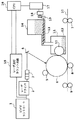
図1は、本発明を適用した画像形成装置の全体構成を示す。ビデオコントローラ1は、ホストコンピュータ等(PC)により作成されある特定の記述言語により記述された信号を受信し、画像形成装置本体のレーザドライバ2により潜像を作成する為の信号処理を行い、レーザドライバ2に信号を送信する。
【0031】
レーザドライバ2は、電気信号(ビデオ信号)に基づきLDによりレーザ光を発光(点灯)させる。LDにより発射されたレーザは高速度で回転するポリゴンミラー3、すなわち、ポリゴンモータ(不図示)に取り付けられたポリゴンミラー3により反射される。反射されたレーザは反射ミラー4によって感光ドラム6表面に照射される。
【0032】
感光ドラム6は予め帯電器5により一定電位に均一に帯電されており、光照射を受けるとこの光照射部位のみ電位が変化することで感光ドラム6上に静電潜像が形成される。
【0033】
現像器11は現像ローラ10及び現像剤12を有する。感光ドラム6上に形成された静電潜像に従い現像ローラ10により現像剤12中トナーのみが感光ドラム6に付着し、画像として具現化される。この画像は、紙,OHTフィルム等に代表される記録部材20に転写器8にて転写される。
【0034】
記録部材20は記録部材搬送ローラ7及び9により搬送される。転写器8により画像を転写された記録部材20は、搬送ローラ9により定着装置(不図示)により永久定着され、画像形成装置外に搬送される。
【0035】
本実施形態では、従来技術で行われていたビデオコントローラ1でのレーザ点灯比率の計数をプリンタエンジン部でのレーザ点灯カウント回路15にて算出することを特徴としている。
【0036】
このため本実施形態では、あらかじめ定められた画像領域内で特定の数だけビデオ信号をサンプルし、ビデオ信号がオンである数をカウントし、そのカウント値と総サンプル数の比率を算出することにより、あらかじめ定められた画像領域内でのレーザ点灯比率を算出する。
【0037】
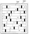
図2を用いて本実施形態でレーザ点灯比率を算出する方法を説明する。図2において112は画像が印刷される用紙を示している。113は前記用紙内での画像が印刷される領域を示している。
【0038】
本実施形態では画像領域113を16分割している。16分割された領域に1から16の番号をつけている。この1から16の画像領域内の1点でビデオ信号をサンプルし、それぞれビデオ信号のオン/オフを判定する。図2の各領域のうち黒く塗りつぶしてある部分でビデオ信号のオン/オフを判定する。
【0039】
ビデオ信号がオンである数をカウントし、その数を分割した画像領域数(この場合は16)で割ることでレーザ点灯比率を算出することができる。上述のようにして算出した値は厳密にいうとレーザ点灯比率と必ずしも一致しない。しかし、サンプルする数が十分大きければ上述のように算出した値と実際のレーザ点灯比率はほぼ等しい。
【0040】
本実施形態の方法では、画像領域内でできるだけ多くのビデオ信号をサンプルすることと、ランダムにビデオ信号をサンプルすることが重要である。上記2つの条件を満たさない場合は、算出したレーザ点灯比率と実際のレーザ点灯比率の誤差が大きくなってしまう。
【0041】
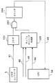
図3は本実施形態のレーザ点灯カウント回路の代表的回路を示したものである。図3を用いてレーザ点灯カウント回路の動作を説明する。これらの回路は同期式のディジタル回路で構成されている。ただし、システムクロックは図示していない。
【0042】
ビデオコントローラ1から入力されたビデオ信号S1をフリップフロップ102で受けて、同期信号にする。サンプルタイミング生成部106では、レーザビームの走査方向の画像領域を示す水平イネーブル信号S3とレーザビームの走査方向と垂直方向の画像印字領域を示す垂直イネーブル信号S2が入力されている。水平イネーブル信号S3は図示しない水平同期信号に基づいてプリンタエンジン内部の制御ロジック回路(不図示)で生成することができる。また、垂直イネーブル信号S2は紙搬送のタイミングに応じてプリンタエンジン内部の制御ロジック回路(不図示)で生成することができる。
【0043】
CPU16は、サンプルタイミング生成部106に、画像領域に応じた設定値S4を入力する。ゲート103はサンプルタイミング生成部106により決められたタイミングでビデオ信号S1を同期化した信号がオンである場合にハイ(HIGH)となる。
【0044】
カウンタ104は、所定の画像領域内でゲート103がハイ(HIGH)となった回数つまりビデオ信号がオンとなった回数をカウントする。上記カウント値は所定の画像領域内における静電潜像作成が終わるとCPU16に送られる(S5)。CPU16は上記カウント値とあらかじめ決められた総サンプル数(たとえば、図2の区間数16)との比率から所定の画像領域内でのレーザ点灯比率を算出することができる。
【0045】
図4はサンプルタイミング生成部106の構成を示す。カウンタ110は図2の16分割されたうちの1つ1つの区間を生成するためのタイマの役割を果たす。詳しくは、画像領域113を全て走査する期間を16等分してその1区間を走査する期間をカウントするカウント値(S8=S4)をCPU16がカウンタ110にロードして、そのカウント値をクロックごとにデクリメントするダウンカウンタを構成する。
【0046】
例えば、本実施形態においては図2の1つの区間を生成するために10クロック分カウントするとした場合、CPU16はカウンタ110にカウント値9をロードする。カウンタ110には、レーザが画像領域内部を走査している期間だけカウンタ110をイネーブルとするカウンタイネーブル信号S7が入力されていて、カウンタ110はレーザが画像領域を走査している期間だけカウント動作を行う。
【0047】
カウンタ110はカウント値が0になると、キャリアウト信号S9を出力し、CPU16からの値S8をロードする。以後この動作を続ける。このようにして、カウンタ110により、画像領域113を16分割することができる。上記のように16分割された各区間のそれぞれ1点でのみビデオ信号のオン/オフを判定する。
【0048】
この1区間内でビデオ信号をサンプルするタイミングはランダムであることが望まれる。リニアフィードバックシフトレジスタ107はランダムな値をレジスタ108にロードするために用いる。カウンタ110の出力S10が0になるタイミングで、キャリアウト信号S9がハイ(HIGH)となり、このリニアフィードバックシフトレジスタ107から出力された値をレジスタ108にロードする。
【0049】
リニアフィードバックシフトレジスタ107は垂直イネーブル信号S2がハイ(HIGH)の期間は動作するので、カウンタ110と動作している期間が同期しなくなるために、出力がランダムになることが期待できる。コンパレータ109はレジスタ108の値とカウンタ110の出力S10とを比較し、両者が一致したタイミングで信号S11をハイ(HIGH)とする。このような構成にすることにより、各区間の中で1回かつ各区間毎にランダムなタイミングでビデオ信号のオン/オフを判定するタイミング信号S6を生成することができる。
【0050】
以上のようにして、プリンタエンジンのCPU16は1ページあたりのレーザ点灯比率を算出することができる。また、レーザ点灯比率と紙サイズをパラメータとしてトナー消費量を求めるテーブル(不図示)をCPU16がアクセスするメモリ(不図示)にあらかじめ記憶しておくことにより、CPU16は上記テーブルを参照しトナー消費量を予測することができる。
【0051】
(実施形態2)
図5は本実施形態のレーザ点灯カウント回路の他の回路の構成を示す。実施形態1で説明した箇所と同じ動作を行う箇所には同じ符号を付している。本実施形態において、プリンタエンジン部は、図5に示したレーザ点灯カウント回路以外の部分は、実施形態1で示した回路を備える。
【0052】
実施形態2のレーザ点灯カウント回路は実施形態1の回路と比べて、CPU16からサンプルタイミング生成部106にロードする信号S4がなくなっており、カウンタ114を追加している。実施形態1では画像を印字する領域に応じてCPU16がロードするカウント値S4の値を変えていた。本実施形態では、サンプルタイミング生成部にロードする値は画像領域によらず一定とする。しかし、この値を一定にすると画像領域により、ビデオ信号S1をサンプルする回数が異なる。したがって、レーザ点灯比率を算出する際の分母の数が画像領域によって異なる。
【0053】
本実施形態ではビデオ信号S1をサンプルする回数をカウントするために、カウンタ114を追加する。カウンタ114により、画像領域内のビデオ信号S1をサンプルした回数をカウントする。
【0054】
カウンタ104によりカウントされた、ビデオ信号がオンであった数S5とサンプル総数S6をCPU16に送ることで、CPU16は画像領域によらず、1ページあたりのレーザ点灯比率を算出することができる。また、レーザ点灯比率と紙サイズをパラメータとしてトナー消費量を求めるテーブル(不図示)をCPU16がアクセスするメモリ(不図示)にあらかじめ記憶しておくことにより、CPU16は上記テーブルを参照しトナー消費量を予測することができる。
【0055】
(実施形態3)
図6は本実施形態のレーザ点灯カウント回路のさらに他の回路を示したものである。実施形態1で説明した箇所と同じ動作を行う箇所には同じ符号を付している。本実施形態において、プリンタエンジン部は、図6に示したレーザ点灯カウント回路以外の部分は、実施形態1で示した回路を備える。
【0056】
実施形態3のレーザ点灯カウント回路は実施形態1の回路と比べて、カウンタ114を追加している点が異なる。実施形態1では画像を印字する領域に応じてCPU16がロードするカウント値S4の値を変えていた。これにより、常に画像領域内でビデオ信号をサンプルする数を常に決められた所定の値としてCPU内部に格納する(たとえば、図2の区間数16)。
【0057】
しかしながら、サンプルする数を所定数(たとえば、16)に合わせるあたり、CPU16が図4のカウンタ110にロードするカウント値(S8=S4)は整数しか設定できないので、印字領域の大きさによっては全領域を走査する期間を上記カウント値で割り切れない場合があり、サンプルする数を所定の数にすることができない場合がある。
【0058】
本実施形態では、レーザ点灯比率を算出する精度を高めるために、画像領域内でサンプルする数をカウントするカウンタ114を追加している。カウンタ114により、画像領域内のビデオ信号S1をサンプルした回数をカウントする。
【0059】
カウンタ104によりカウントされた、ビデオ信号がオンであった数S5とサンプル総数S6をCPU16に送ることで、CPU16は高精度に1ページあたりのレーザ点灯比率を算出することができる。また、レーザ点灯比率と紙サイズをパラメータとしてトナー消費量を求めるテーブル(不図示)をCPU16がアクセスするメモリ(不図示)にあらかじめ記憶しておくことにより、CPU16は上記テーブルを参照しトナー消費量を予測することができる。
【0060】
(実施形態総括)
以上、本発明の実施形態で説明した方法で、レーザ点灯比率を算出することにより、トナー消費量を予測できる。このため、CPU16はトナー消費量の予測値に基づいて、以下のトナー補給シーケンスにより的確なトナー補給が可能となり、現像器11内の現像剤12の濃度を一定に保つ様にしている。
【0061】
図1を参照して、トナー補給方法について説明する。本発明の実施形態で説明した方法により、CPU16は1ページあたりのレーザ点灯比率を算出することができる。実際のトナー補給量は、紙サイズと上記レーザ点灯比率をパラメータとして、図1のモータ18の回転量をCPU16が制御することにより制御される。
【0062】
例えば、A4サイズでレーザ点灯比率が50%の場合は、モータ18を1回転だけ回転させることによりトナー補給を行う、というように制御することができる。この制御のためのデータとして、紙サイズとレーザ点灯比率をパラメータとした最適なモータ18の回転量のテーブル(不図示)をCPU16がアクセスするメモリ(不図示)に記憶しておくと良い。なお、ここで述べたモータ回転量は一例であって、このモータ回転量に限定されるものではない。
【0063】
また本発明の実施形態では、単色の画像形成装置にて説明を進めたが、多色画像形成装置等にも適用することが可能である。
【0064】
上記各実施形態においては、トナー消費量の予測値に基づいてトナー濃度を調整するものとして説明をしたが、CPU16が上記予測値を定着装置の温度制御のパラメータとして利用することも可能である。例えば、トナー消費量が多い(レーザ点灯比率が高い)と予測できた場合は、定着装置の温度を高く設定して定着性を高める、等である。
【0065】
上記予測値に基づいてCPU16が定着装置の温度制御を行う方法を説明する。本発明の実施形態で説明した方法により、CPU16は1ページあたりのレーザ点灯比率を算出することができる。上記レーザ点灯比率をパラメータとしたレーザ点灯比率に対応する定着装置の温度をテーブル(不図示)として、CPU16がアクセスするメモリ(不図示)に記憶しておくことにより、定着装置の温度を最適な値に制御することができる。例えば、レーザ点灯比率が20%未満の場合の定着装置の温度を180℃、20%以上50%未満の時の温度を190℃、50%以上の時の温度を200℃などに設定することにより、定着性を高めることができる。最適な定着装置の温度は一例であって、この温度に限定されるものではない。
以上、説明したように、ビデオ信号のオンの数をカウントし、そのカウント値に基づき、光(レーザ)の点灯比率を算出する。このため、算出したレーザ点灯比率からトナー消費量を正確に予測することができる。これにより、的確なトナー補給が可能となり濃度むらの少ない安定した画像の継続的出力が可能となる。また、回路構成についてもディジタル回路のみで構成でき、エンジン制御ロジック回路内部で安価に構成できる。
【0066】
【発明の効果】
以上、説明したように、本発明によれば、安価な構成でトナー消費量の予測に係る処理を行う事が可能となる。
【図面の簡単な説明】
【図1】本発明実施形態のプリンタの全体構成図である。
【図2】本発明実施形態のレーザ点灯比率を算出する方法の説明図である。
【図3】本発明実施形態の第1の実施形態の説明図である。
【図4】本発明実施形態のサンプルタイミング生成部の構成図である。
【図5】本発明実施形態の第2の実施形態の説明図である。
【図6】本発明実施形態の第3の実施形態の説明図である。
【図7】従来のプリンタの全体構成図である。
【符号の説明】
1 ビデオコントローラ
2 レーザドライバ
3 ポリゴンミラー
4 反射ミラー
5 帯電器
6 感光ドラム
7 記録部材搬送ローラ7
8 転写器
9 記録部材搬送ローラ
10 現像ローラ
11 現像器
12 現像剤
13 スクリュ
14 トナー補給容器
15 レーザ点灯カウント回路
16 CPU
17 モータドライバ基板
18 モータ
19 ギヤ
20 記録部材
102 フリップフロップ
103 ゲート
104 カウンタ
106 サンプルタイミング生成部
107 リニアフィードバックシフトレジスタ
108 レジスタ
109 コンパレータ
110 カウンタ
112 用紙
113 画像領域
114 カウンタ
S1 ビデオ信号
S2 垂直イネーブル信号
S3 水平イネーブル信号
S4 1区間を走査する期間のカウント値
S5 ビデオ信号がオンであったカウント値
S6 サンプル総数
S7 カウンタイネーブル信号
S8 1区間を走査する期間のカウント値
S9 キャリアウト信号
S10 カウンタ出力
S11 タイミング信号[0001]
BACKGROUND OF THE INVENTION
The present invention relates to an image forming apparatus and method for realizing an electrostatic latent image using an electrophotographic process. More specifically, a laser beam printer, a copier, a technique about the prediction of our Keru toner consumption facsimile.
[0002]
[Prior art]
Laser beam printers, copiers, and facsimile machines that perform image formation using an electrophotographic process use a two-component developer mainly composed of toner and a carrier. In the case of this method, the ratio of toner to carrier is extremely important for the image density. At the time of development, since the toner is consumed and the carrier is not consumed among the mixed toner and carrier, the ratio of the toner and the carrier changes. In an image forming apparatus using a two-component developer for this purpose, in order to accurately predict the toner consumption of the developer and to replenish the toner appropriately according to the prediction result, the toner and carrier inside the developing device are mixed. Equipped with a sensor to detect the ratio.
[0003]
FIG. 7 shows the overall configuration of a conventional image forming apparatus having a density control function using a sensor for detecting the mixing ratio of toner and carrier in the developing unit.
[0004]
The
[0005]
The
[0006]
The
[0007]
The developing
[0008]
The
[0009]
The developing
[0010]
Further, the
[0011]
The
[0012]
The
[0013]
[Problems to be solved by the invention]
However, in the above-described prior art, since the video controller counts the lighting ratio of the LD, in addition to bearing elements that must be controlled by the printer engine, the edge portion of the image is detected. Since smoothing processing for smoothing or processing for imparting gradation to the image is performed, the logic scale for the counting becomes large, which causes a cost increase.
[0014]
Furthermore, since the amount of information acquired by the printer engine CPU becomes enormous, the amount of processing work in the printer engine CPU increases, which also causes an increase in cost. There was.
[0015]
Accordingly, an object of the present invention is to enable processing related to prediction of toner consumption with an inexpensive configuration.
[0016]
[Means for Solving the Problems]
In order to achieve such an object, the present invention provides a laser beam light emitting element, laser control means for controlling light emission of the laser beam light emitting element based on an input signal, and light emission based on the laser beam light emitting element. An image forming apparatus comprising: an image carrier that forms an electrostatic latent image; and a developing unit that attaches toner to the electrostatic latent image on the image carrier and visualizes the image as a toner image. A video signal for controlling the light emission of the laser beam light emitting element, and counting means for counting the input video signal. The counting means is an image of one page for the input video signal. Without counting the video signal of all areas, the video signal is counted at a plurality of random locations in the entire image area of one page, Predict the toner consumption according to the ratio of the number of video signals that emit light from the laser beam emitting element in the count with respect to the number of samples of the video signal, or count with respect to the number of samples of the video signal in a plurality of locations. A process corresponding to a toner consumption amount corresponding to a ratio of the number of video signals to be emitted from the laser beam light emitting element is performed.
[0029]
DETAILED DESCRIPTION OF THE INVENTION
Hereinafter, embodiments of the present invention will be described in detail with reference to the drawings. In addition, the same code | symbol is attached | subjected to the same location in each drawing also including the above-mentioned prior art.
[0030]
(Embodiment 1)
FIG. 1 shows the overall configuration of an image forming apparatus to which the present invention is applied. The
[0031]
The
[0032]
The
[0033]
The developing
[0034]
The recording
[0035]
This embodiment is characterized in that the laser lighting ratio count in the
[0036]
For this reason, in this embodiment, a specific number of video signals are sampled within a predetermined image area, the number of video signals that are on is counted, and the ratio between the count value and the total number of samples is calculated. The laser lighting ratio in a predetermined image area is calculated.
[0037]
A method of calculating the laser lighting ratio in this embodiment will be described with reference to FIG. In FIG. 2,
[0038]
In this embodiment, the
[0039]
The laser lighting ratio can be calculated by counting the number of video signals turned on and dividing the number by the number of divided image areas (16 in this case). Strictly speaking, the value calculated as described above does not necessarily match the laser lighting ratio. However, if the number of samples is sufficiently large, the value calculated as described above and the actual laser lighting ratio are substantially equal.
[0040]
In the method of this embodiment, it is important to sample as many video signals as possible within an image region and to sample video signals randomly. If the above two conditions are not satisfied, the error between the calculated laser lighting ratio and the actual laser lighting ratio becomes large.
[0041]
FIG. 3 shows a typical circuit of the laser lighting count circuit of this embodiment. The operation of the laser lighting count circuit will be described with reference to FIG. These circuits are composed of synchronous digital circuits. However, the system clock is not shown.
[0042]
The video signal S1 input from the
[0043]
The
[0044]
The
[0045]
FIG. 4 shows the configuration of the sample
[0046]
For example, in this embodiment, when counting 10 clocks to generate one section of FIG. 2, the
[0047]
When the count value reaches 0, the
[0048]
It is desirable that the timing for sampling the video signal within one section is random. The linear
[0049]
Since the linear
[0050]
As described above, the
[0051]
(Embodiment 2)
FIG. 5 shows the configuration of another circuit of the laser lighting count circuit of this embodiment. Parts that perform the same operations as those described in the first embodiment are denoted by the same reference numerals. In this embodiment, the printer engine unit includes the circuit shown in the first embodiment except for the laser lighting count circuit shown in FIG.
[0052]
Compared with the circuit of the first embodiment, the laser lighting count circuit of the second embodiment has no signal S4 loaded from the
[0053]
In the present embodiment, a
[0054]
By sending the number S5 of video signals turned on and the total number of samples S6 counted by the
[0055]
(Embodiment 3)
FIG. 6 shows still another circuit of the laser lighting count circuit of this embodiment. Parts that perform the same operations as those described in the first embodiment are denoted by the same reference numerals. In this embodiment, the printer engine unit includes the circuit shown in the first embodiment except for the laser lighting count circuit shown in FIG.
[0056]
The laser lighting count circuit according to the third embodiment is different from the circuit according to the first embodiment in that a
[0057]
However, when the number of samples is adjusted to a predetermined number (for example, 16), the count value (S8 = S4) that the
[0058]
In the present embodiment, a
[0059]
By sending the number S5 of video signals turned on and the total number of samples S6 counted by the
[0060]
(Embodiment summary)
As described above, the toner consumption amount can be predicted by calculating the laser lighting ratio by the method described in the embodiment of the present invention. For this reason, the
[0061]
A toner replenishing method will be described with reference to FIG. With the method described in the embodiment of the present invention, the
[0062]
For example, when the A4 size and the laser lighting ratio is 50%, it is possible to perform control such that toner is supplied by rotating the
[0063]
In the embodiment of the present invention, the description has been made on a single-color image forming apparatus, but the present invention can also be applied to a multicolor image forming apparatus.
[0064]
In each of the above embodiments, the toner density is adjusted based on the predicted value of toner consumption. However, the
[0065]
A method in which the
As described above, the number of ON of the video signal is counted, and the lighting ratio of light (laser) is calculated based on the count value. For this reason, the toner consumption can be accurately predicted from the calculated laser lighting ratio. As a result, accurate toner replenishment can be performed, and a stable image with less uneven density can be continuously output. Also, the circuit configuration can be configured only with a digital circuit, and can be configured at low cost inside the engine control logic circuit.
[0066]
【The invention's effect】
As described above, according to the present invention, it is possible to perform processing related to prediction of toner consumption with an inexpensive configuration.
[Brief description of the drawings]
FIG. 1 is an overall configuration diagram of a printer according to an embodiment of the present invention.
FIG. 2 is an explanatory diagram of a method for calculating a laser lighting ratio according to an embodiment of the present invention.
FIG. 3 is an explanatory diagram of a first embodiment of the present invention.
FIG. 4 is a configuration diagram of a sample timing generation unit according to the embodiment of the present invention.
FIG. 5 is an explanatory diagram of a second embodiment of the present invention.
FIG. 6 is an explanatory diagram of a third embodiment of the present invention.
FIG. 7 is an overall configuration diagram of a conventional printer.
[Explanation of symbols]
DESCRIPTION OF
8
17
Claims (8)
前記レーザ制御手段に入力される信号であって、前記レーザビーム発光素子の発光を制御するためのビデオ信号を入力し、前記入力されたビデオ信号をカウントするカウント手段を備え、
前記カウント手段は、前記入力されたビデオ信号について、1ページの画像領域全ての前記ビデオ信号をカウントすることなく、1ページの全画像領域におけるランダムな複数の箇所で前記ビデオ信号をカウントし、
前記複数の箇所における前記ビデオ信号のサンプル数に対する前記カウントでの前記レーザビーム発光素子を発光させるビデオ信号の数の比率に応じたトナー消費量に係る予測を行う、或いは、前記複数の箇所における前記ビデオ信号のサンプル数に対する前記カウントでの前記レーザビーム発光素子を発光させるビデオ信号の数の比率に応じたトナー消費量に対応した処理を行うことを特徴とする画像形成装置。A laser beam light emitting element; laser control means for controlling light emission of the laser beam light emitting element based on an input signal; an image carrier for forming an electrostatic latent image based on light emission by the laser beam light emitting element; An image forming apparatus comprising: a developing unit that attaches toner to an electrostatic latent image on an image carrier and visualizes the toner image;
A signal input to the laser control means , comprising a video signal for controlling light emission of the laser beam light emitting element, and a counting means for counting the input video signal,
Said counting means, for the input video signal, without counting the image region all of the video signal for one page, and counting the video signal at random a plurality of locations in the entire image region for one page,
Predicting toner consumption according to the ratio of the number of video signals that cause the laser beam emitting element to emit light at the count with respect to the number of samples of the video signal at the plurality of locations, or at the plurality of locations An image forming apparatus that performs processing corresponding to a toner consumption amount according to a ratio of a number of video signals that cause the laser beam light emitting element to emit light at the count with respect to the number of samples of video signals .
前記カウント手段は、前記生成されたランダムな箇所を示すビデオ信号に従い前記入力されたビデオ信号をカウントすることを特徴とする請求項2に記載の画像形成装置。Wherein in response to each of the sampling interval, further comprising a random signal generating means for generating a video signal indicating a random position to count the video signal,
The counting means, the image forming apparatus according to claim 2, characterized in that counting the video signal the input in accordance with a video signal indicating a random location that is generated.
前記レーザ制御手段に入力される信号であって、前記レーザビーム発光素子の発光を制御するためのビデオ信号を入力し、前記入力されたビデオ信号をカウントするカウント工程を備え、
前記カウント工程が、前記入力されたビデオ信号について、1ページの画像領域全ての前記ビデオ信号をカウントすることなく、1ページの全画像領域におけるランダムな複数の箇所で前記ビデオ信号をカウントし、
前記複数の箇所における前記ビデオ信号のサンプル数に対する前記カウントでの前記レーザビーム発光素子を発光させるビデオ信号の数の比率に応じたトナー消費量に係る予測を行う、或いは、前記複数の箇所における前記ビデオ信号のサンプル数に対する前記カウントでの前記レーザビーム発光素子を発光させるビデオ信号の数の比率に応じたトナー消費量に対応した処理を行う工程を有することを特徴とする画像形成方法。A laser beam light emitting element; laser control means for controlling light emission of the laser beam light emitting element based on an input signal; an image carrier for forming an electrostatic latent image based on light emission by the laser beam light emitting element; An image forming method in an image forming apparatus comprising: a developing device that attaches toner to an electrostatic latent image on an image carrier and visualizes the toner image;
A signal input to the laser control means, the video signal for controlling the light emission of the laser beam light emitting element is input, and a counting step of counting the input video signal is provided.
The counting step, for the input video signal, without counting the image region all of the video signal for one page, and counting the video signal at random a plurality of locations in the entire image region for one page,
Predicting toner consumption according to the ratio of the number of video signals that cause the laser beam emitting element to emit light at the count with respect to the number of samples of the video signal at the plurality of locations, or at the plurality of locations An image forming method comprising: performing a process corresponding to a toner consumption amount according to a ratio of a number of video signals for causing the laser beam emitting element to emit light at the count with respect to a number of samples of a video signal .
前記カウント工程が、前記生成されたランダムな箇所を示すビデオ信号に従い前記入力されたビデオ信号をカウントすることを特徴とする請求項6に記載の画像形成方法。A random signal generating step of generating a video signal indicating a random location for counting the video signal corresponding to each of the sample sections;
The counting process, the image forming method according to claim 6, characterized in that counting the input video signal in accordance with a video signal representing a random location that is generated.
Priority Applications (1)
| Application Number | Priority Date | Filing Date | Title |
|---|---|---|---|
| JP2000256323A JP4822578B2 (en) | 2000-08-25 | 2000-08-25 | Image forming apparatus and method |
Applications Claiming Priority (1)
| Application Number | Priority Date | Filing Date | Title |
|---|---|---|---|
| JP2000256323A JP4822578B2 (en) | 2000-08-25 | 2000-08-25 | Image forming apparatus and method |
Publications (3)
| Publication Number | Publication Date |
|---|---|
| JP2002072770A JP2002072770A (en) | 2002-03-12 |
| JP2002072770A5 JP2002072770A5 (en) | 2010-06-17 |
| JP4822578B2 true JP4822578B2 (en) | 2011-11-24 |
Family
ID=18744951
Family Applications (1)
| Application Number | Title | Priority Date | Filing Date |
|---|---|---|---|
| JP2000256323A Expired - Lifetime JP4822578B2 (en) | 2000-08-25 | 2000-08-25 | Image forming apparatus and method |
Country Status (1)
| Country | Link |
|---|---|
| JP (1) | JP4822578B2 (en) |
Cited By (2)
| Publication number | Priority date | Publication date | Assignee | Title |
|---|---|---|---|---|
| US9035989B2 (en) | 2012-12-13 | 2015-05-19 | Canon Kabushiki Kaisha | Image forming apparatus with count portion measuring electric signal |
| US9323173B2 (en) | 2013-12-25 | 2016-04-26 | Canon Kabushiki Kaisha | Image forming apparatus |
Families Citing this family (1)
| Publication number | Priority date | Publication date | Assignee | Title |
|---|---|---|---|---|
| US9772578B2 (en) | 2015-06-22 | 2017-09-26 | Canon Kabushiki Kaisha | Image forming apparatus and method for counting image signals with changed image signal width |
Family Cites Families (4)
| Publication number | Priority date | Publication date | Assignee | Title |
|---|---|---|---|---|
| JPH0239178A (en) * | 1988-07-29 | 1990-02-08 | Ricoh Co Ltd | Toner exhaustion detecting device for image forming device |
| JPH0730758A (en) * | 1993-07-14 | 1995-01-31 | Minolta Co Ltd | Base density level detector for original image for image forming device |
| JP3142108B2 (en) * | 1994-11-07 | 2001-03-07 | 株式会社東芝 | Image processing apparatus and image processing method |
| JPH11320910A (en) * | 1998-05-11 | 1999-11-24 | Seiko Epson Corp | Printing system, printer, printing data generation apparatus and print method |
-
2000
- 2000-08-25 JP JP2000256323A patent/JP4822578B2/en not_active Expired - Lifetime
Cited By (2)
| Publication number | Priority date | Publication date | Assignee | Title |
|---|---|---|---|---|
| US9035989B2 (en) | 2012-12-13 | 2015-05-19 | Canon Kabushiki Kaisha | Image forming apparatus with count portion measuring electric signal |
| US9323173B2 (en) | 2013-12-25 | 2016-04-26 | Canon Kabushiki Kaisha | Image forming apparatus |
Also Published As
| Publication number | Publication date |
|---|---|
| JP2002072770A (en) | 2002-03-12 |
Similar Documents
| Publication | Publication Date | Title |
|---|---|---|
| JP4355636B2 (en) | Image forming apparatus | |
| US8264508B2 (en) | Image forming apparatus and method for controlling the same | |
| JP2008076895A (en) | Toner supply device and image forming apparatus | |
| JP2001042613A (en) | Developing device and image forming device provided with the developing device | |
| JP4822578B2 (en) | Image forming apparatus and method | |
| JP2004104888A (en) | Control device for stepping motor drive, document scanner and image forming device | |
| JP4950601B2 (en) | Toner supply controller and image forming apparatus | |
| JP2004163885A (en) | Image forming apparatus and method for estimating amount of toner consumption | |
| US8892007B2 (en) | Image forming apparatus, toner supplying method, and computer program product | |
| JP2009169307A (en) | Toner replenishing device, and image forming device | |
| JP2004191559A (en) | Toner supply system | |
| JP5357508B2 (en) | Image forming apparatus, control method therefor, and program | |
| JP3053915B2 (en) | Image forming device | |
| JP2002283616A (en) | Imaging apparatus and its laser diode controlling method | |
| JP2003280356A (en) | Image forming apparatus | |
| WO2010029711A1 (en) | Image-forming device and control method therefor | |
| JP6361285B2 (en) | Image forming apparatus | |
| JP2942017B2 (en) | Image forming device | |
| JP2002287440A (en) | Image forming device | |
| US20230400804A1 (en) | Image forming apparatus that forms image on sheet using tone correction condition corresponding to process speed | |
| JP2942018B2 (en) | Image forming device | |
| JP6781936B2 (en) | Image forming device | |
| JPH0667535A (en) | Image forming device | |
| JP3074040B2 (en) | Image forming device | |
| JP2010250214A (en) | Image forming apparatus |
Legal Events
| Date | Code | Title | Description |
|---|---|---|---|
| A621 | Written request for application examination |
Free format text: JAPANESE INTERMEDIATE CODE: A621 Effective date: 20070827 |
|
| A977 | Report on retrieval |
Free format text: JAPANESE INTERMEDIATE CODE: A971007 Effective date: 20100402 |
|
| A521 | Written amendment |
Free format text: JAPANESE INTERMEDIATE CODE: A523 Effective date: 20100423 |
|
| A131 | Notification of reasons for refusal |
Free format text: JAPANESE INTERMEDIATE CODE: A131 Effective date: 20100511 |
|
| A521 | Written amendment |
Free format text: JAPANESE INTERMEDIATE CODE: A523 Effective date: 20100712 |
|
| A131 | Notification of reasons for refusal |
Free format text: JAPANESE INTERMEDIATE CODE: A131 Effective date: 20101026 |
|
| RD02 | Notification of acceptance of power of attorney |
Free format text: JAPANESE INTERMEDIATE CODE: A7422 Effective date: 20101106 |
|
| A521 | Written amendment |
Free format text: JAPANESE INTERMEDIATE CODE: A523 Effective date: 20101227 |
|
| A131 | Notification of reasons for refusal |
Free format text: JAPANESE INTERMEDIATE CODE: A131 Effective date: 20110401 |
|
| A521 | Written amendment |
Free format text: JAPANESE INTERMEDIATE CODE: A523 Effective date: 20110531 |
|
| TRDD | Decision of grant or rejection written | ||
| A01 | Written decision to grant a patent or to grant a registration (utility model) |
Free format text: JAPANESE INTERMEDIATE CODE: A01 Effective date: 20110902 |
|
| A01 | Written decision to grant a patent or to grant a registration (utility model) |
Free format text: JAPANESE INTERMEDIATE CODE: A01 |
|
| A61 | First payment of annual fees (during grant procedure) |
Free format text: JAPANESE INTERMEDIATE CODE: A61 Effective date: 20110906 |
|
| R151 | Written notification of patent or utility model registration |
Ref document number: 4822578 Country of ref document: JP Free format text: JAPANESE INTERMEDIATE CODE: R151 |
|
| FPAY | Renewal fee payment (event date is renewal date of database) |
Free format text: PAYMENT UNTIL: 20140916 Year of fee payment: 3 |
|
| EXPY | Cancellation because of completion of term |