JP6235233B2 - Image forming apparatus - Google Patents
Image forming apparatus Download PDFInfo
- Publication number
- JP6235233B2 JP6235233B2 JP2013095667A JP2013095667A JP6235233B2 JP 6235233 B2 JP6235233 B2 JP 6235233B2 JP 2013095667 A JP2013095667 A JP 2013095667A JP 2013095667 A JP2013095667 A JP 2013095667A JP 6235233 B2 JP6235233 B2 JP 6235233B2
- Authority
- JP
- Japan
- Prior art keywords
- image
- recording material
- photosensitive drum
- pixel
- equation
- Prior art date
- Legal status (The legal status is an assumption and is not a legal conclusion. Google has not performed a legal analysis and makes no representation as to the accuracy of the status listed.)
- Active
Links
- 238000004140 cleaning Methods 0.000 claims description 125
- 238000012546 transfer Methods 0.000 claims description 74
- 230000008859 change Effects 0.000 claims description 9
- 230000015572 biosynthetic process Effects 0.000 claims description 5
- 239000000463 material Substances 0.000 description 229
- 230000007423 decrease Effects 0.000 description 90
- 230000006866 deterioration Effects 0.000 description 90
- 230000009467 reduction Effects 0.000 description 79
- 238000011084 recovery Methods 0.000 description 76
- 230000006872 improvement Effects 0.000 description 65
- 238000000034 method Methods 0.000 description 50
- 230000032258 transport Effects 0.000 description 44
- 230000008569 process Effects 0.000 description 42
- 238000011161 development Methods 0.000 description 19
- 230000018109 developmental process Effects 0.000 description 19
- 230000007547 defect Effects 0.000 description 17
- 238000001514 detection method Methods 0.000 description 10
- 239000000428 dust Substances 0.000 description 7
- CBENFWSGALASAD-UHFFFAOYSA-N Ozone Chemical compound [O-][O+]=O CBENFWSGALASAD-UHFFFAOYSA-N 0.000 description 5
- 239000000654 additive Substances 0.000 description 5
- 230000000694 effects Effects 0.000 description 5
- 230000014509 gene expression Effects 0.000 description 5
- 239000000454 talc Substances 0.000 description 4
- 229910052623 talc Inorganic materials 0.000 description 4
- 238000010586 diagram Methods 0.000 description 3
- 230000002093 peripheral effect Effects 0.000 description 3
- 239000000126 substance Substances 0.000 description 3
- 238000002474 experimental method Methods 0.000 description 2
- 238000012545 processing Methods 0.000 description 2
- 230000001105 regulatory effect Effects 0.000 description 2
- 238000007790 scraping Methods 0.000 description 2
- 238000003756 stirring Methods 0.000 description 2
- 239000004094 surface-active agent Substances 0.000 description 2
- XLYOFNOQVPJJNP-UHFFFAOYSA-N water Substances O XLYOFNOQVPJJNP-UHFFFAOYSA-N 0.000 description 2
- 238000005299 abrasion Methods 0.000 description 1
- 230000004323 axial length Effects 0.000 description 1
- 230000015556 catabolic process Effects 0.000 description 1
- 239000011248 coating agent Substances 0.000 description 1
- 238000000576 coating method Methods 0.000 description 1
- 238000009833 condensation Methods 0.000 description 1
- 230000005494 condensation Effects 0.000 description 1
- 238000006731 degradation reaction Methods 0.000 description 1
- 230000005684 electric field Effects 0.000 description 1
- 230000007613 environmental effect Effects 0.000 description 1
- 239000000835 fiber Substances 0.000 description 1
- 230000006870 function Effects 0.000 description 1
- 238000010438 heat treatment Methods 0.000 description 1
- 238000009434 installation Methods 0.000 description 1
- 230000001678 irradiating effect Effects 0.000 description 1
- 238000005259 measurement Methods 0.000 description 1
- 238000005498 polishing Methods 0.000 description 1
- 238000003825 pressing Methods 0.000 description 1
- 239000000758 substrate Substances 0.000 description 1
- 230000001360 synchronised effect Effects 0.000 description 1
Images


Landscapes
- Cleaning In Electrography (AREA)
- Control Or Security For Electrophotography (AREA)
- Physics & Mathematics (AREA)
- General Physics & Mathematics (AREA)
Description
本発明は、複写機、レーザビームプリンタ等の画像形成装置に関するものである。 The present invention relates to an image forming apparatus such as a copying machine or a laser beam printer.
最近ではコンピュータ等の出力装置として画像形成装置が世界各国に普及している。そのため、高温多湿環境でも高品質の画像が得られることが要求されている。また、使用される記録材としても世界各国で多種多様の記録材が生産使用されるため、それに適応出来ることが望まれている。 Recently, image forming apparatuses have become widespread throughout the world as output devices such as computers. Therefore, it is required to obtain a high quality image even in a high temperature and high humidity environment. In addition, since a wide variety of recording materials are produced and used in various countries as recording materials to be used, it is desired to be able to adapt to them.
例えば、高温多湿環境下における問題として、「画像流れ」が知られている。「画像流れ」は感光ドラムの表面に結露することによっても発生する。また、記録材に含まれる繊維や添加剤等の異物が感光ドラムの表面に付着する。そして、帯電装置により発生するオゾンから出来る酸化物と多湿環境下による水分とが化合して低抵抗物が生成される。この低抵抗物により感光ドラムの表面上に形成される静電潜像が乱されて「画像流れ」を引き起こす。 For example, “image flow” is known as a problem in a hot and humid environment. The “image flow” is also generated by condensation on the surface of the photosensitive drum. Further, foreign matters such as fibers and additives contained in the recording material adhere to the surface of the photosensitive drum. And the oxide made from ozone which generate | occur | produces with a charging device and the water | moisture content by a humid environment combine, and a low resistance thing is produced | generated. This low resistance material disturbs the electrostatic latent image formed on the surface of the photosensitive drum and causes “image flow”.
また、記録材として使用されるOHT(OverHead Transparency)シート(OHP(OverHead Projector)に使用される透明なシート)の表面に界面活性剤が設けられる。その界面活性剤が感光ドラムの表面上に付着して「画像流れ」が起きることもある。 Further, a surfactant is provided on the surface of an OHT (OverHead Transparency) sheet (transparent sheet used for OHP (OverHead Projector)) used as a recording material. The surfactant may adhere to the surface of the photosensitive drum and “image flow” may occur.
この「画像流れ」の問題を解決する方法としては、クリーニング装置により感光ドラムの表面上をクリーニングする時間を延長したり、クリーニング装置のクリーニング性能を向上させて感光ドラムの表面に付着した異物を除去する。或いは、感光ドラムの内部にヒータを設けて、該感光ドラムの温度を周辺の雰囲気温度よりも上げることで該感光ドラムの表面の湿度を下げ、低抵抗物の発生を抑制するものが提案されている。 As a method for solving this “image flow” problem, the cleaning device can be used to extend the time for cleaning the surface of the photosensitive drum, or to improve the cleaning performance of the cleaning device to remove foreign matter adhering to the surface of the photosensitive drum. To do. Alternatively, it has been proposed to provide a heater inside the photosensitive drum and raise the temperature of the photosensitive drum above the ambient temperature to lower the humidity of the surface of the photosensitive drum and suppress the generation of low resistance materials. Yes.
例えば、クリーニング装置により感光ドラムの表面上をクリーニングする時間を延長したり、クリーニング装置のクリーニング性能を向上させて感光ドラムの表面に付着した異物を除去する。このような方法によると、クリーニング時間の延長やクリーニング性能の向上には限界がある。感光ドラムの表面上の異物を除去する能力を向上させればさせる程、感光ドラムの表面の削れ量が増加する。これにより、感光ドラムの寿命が短縮し、クリーニング装置の耐久性が低下する等の問題がある。 For example, the cleaning device extends the time for cleaning the surface of the photosensitive drum, or improves the cleaning performance of the cleaning device to remove foreign matter adhering to the surface of the photosensitive drum. According to such a method, there is a limit in extending the cleaning time and improving the cleaning performance. As the ability to remove foreign matter on the surface of the photosensitive drum is improved, the amount of abrasion on the surface of the photosensitive drum increases. As a result, the life of the photosensitive drum is shortened, and the durability of the cleaning device is lowered.
一方、感光ドラムの内部にヒータを設けて該感光ドラムの表面の湿度を下げ、低抵抗物の発生を抑制する方法によると、新たにヒータを設けなければならない。このため、コスト高になってしまい、小型プリンタ等の画像形成装置には採用し難い。 On the other hand, according to the method of providing a heater inside the photosensitive drum to reduce the humidity of the surface of the photosensitive drum and suppressing the generation of low resistance, a new heater must be provided. For this reason, the cost is increased, and it is difficult to employ the image forming apparatus such as a small printer.
例えば、特許文献1には、高温高湿環境で画像流れまでの時間を、感光ドラムの回転時間や、印字率、印字枚数等から求めて適切なタイミングでクリーニング動作を行うことで画像流れを防止する技術が提案されている。 For example, Japanese Patent Laid-Open No. 2004-228867 prevents image flow by performing a cleaning operation at an appropriate timing by obtaining the time until image flow in a high-temperature and high-humidity environment from the rotation time of the photosensitive drum, the print rate, the number of prints, etc. Techniques to do this have been proposed.
しかしながら、特許文献1の技術では、搬送される記録材の端部位置に着目して画像流れの発生度合いを判断するものではなかった。
However, the technique of
本発明は、像担持体の状態変化による画像不良を防止できる画像形成装置を提供するものである。 The present invention is to provide an image forming apparatus that can prevent image defect due to a state change of the image carrier.
前記目的を達成するための本発明に係る画像形成装置の代表的な構成は、像担持体との間に形成されるニップ部を挟持搬送される記録シートへ前記像担持体に形成された画像を転写する転写手段と、所定サイズの記録シートが前記ニップ部を通過する時の前記所定サイズの記録シートの搬送方向における長さの積算長さから、前記所定サイズの記録シートを越えるサイズのシートが前記ニップ部を通過する時の前記越えるサイズのシートの搬送方向における長さの積算長さを除いた値に基づいて前記像担持体の状態変化を判定する判定手段と、を有することを特徴とする。 In order to achieve the above object, a typical configuration of an image forming apparatus according to the present invention is an image formed on the image carrier to a recording sheet that is nipped and conveyed with a nip formed between the image carrier and the image carrier. And a sheet having a size exceeding the recording sheet of the predetermined size from the integrated length of the length in the conveying direction of the recording sheet of the predetermined size when the recording sheet of the predetermined size passes through the nip portion. Determining means for determining a change in the state of the image carrier based on a value excluding an integrated length of the length in the conveyance direction of the oversized sheet when passing through the nip portion. And
本発明の画像形成装置は、像担持体の状態変化による画像不良を防止できる。 The image forming apparatus of the present invention can prevent image defects due to a change in the state of the image carrier.
図により本発明に係る画像形成装置の一実施形態を具体的に説明する。尚、以下の各実施形態において、「縦方向」とは、記録材P(記録シート)の搬送方向が長手方向となる方向とし、「横方向」とは、記録材Pの搬送方向が短手方向となる方向として説明する。 An embodiment of an image forming apparatus according to the present invention will be specifically described with reference to the drawings. In each of the following embodiments, the “longitudinal direction” is a direction in which the conveyance direction of the recording material P (recording sheet) is the longitudinal direction, and the “lateral direction” is the short conveyance direction of the recording material P. It demonstrates as a direction used as a direction.
先ず、図1〜図8を用いて本発明に係る画像形成装置の第1実施形態の構成について説明する。 First, the configuration of the first embodiment of the image forming apparatus according to the present invention will be described with reference to FIGS.
図1はプロセスカートリッジを着脱可能に構成したレーザビームプリンタからなる画像形成装置Mの概略構成を示す断面説明図である。図1において、1は所定のプロセススピード(周速度)で図1の矢印R1方向に回転可能で表面に像が担持される像担持体となる円筒状の感光ドラムである。感光ドラム1は、図1の矢印R2方向に回転する帯電手段となる帯電ローラ2によりその表面が一様に帯電される。帯電ローラ2により一様に帯電された感光ドラム1の表面は、露光手段となる露光装置3により露光されて静電潜像が形成される。
FIG. 1 is a cross-sectional explanatory view showing a schematic configuration of an image forming apparatus M composed of a laser beam printer in which a process cartridge is detachable. In FIG. 1,
感光ドラム1の表面に形成された静電潜像に現像剤となるトナーTを供給して現像する現像手段となる現像装置4は、トナーTを収容するトナー容器4aを有する。更に、図1の矢印R4方向に回転することで表面に担持したトナーTを感光ドラム1の表面に対向する現像位置に搬送する現像剤担持体となる現像スリーブ4bを有する。更に、該現像スリーブ4bの表面に担持されるトナーTの層厚を規制する現像剤規制部材となる現像ブレード4cと、トナー容器4a内のトナーTを攪拌し、現像スリーブ4bに向けて搬送する撹拌部材4dとを備えている。
A developing device 4 serving as a developing unit that supplies toner T as a developer to the electrostatic latent image formed on the surface of the
現像スリーブ4bの表面上に付着したトナーTは感光ドラム1の表面上に形成された静電潜像に供給されて現像剤像となるトナー像として現像される。
The toner T adhering to the surface of the developing
現像スリーブ4bの外周面近傍には現像剤規制部材となる現像ブレード4cが設けられている。現像ブレード4cはトナー容器4a内に回転可能に設けられた撹拌部材4dによって攪拌搬送されて現像スリーブ4bの表面に担持されたトナーの層厚を規制する。
A developing
そして、画像形成するためのバイアス電圧を供給する高圧回路を備えた図示しないエンジン制御部により、感光ドラム1と現像スリーブ4bとの間に直流バイアスに交流バイアスを重畳した現像バイアス電圧を印加する。
A developing bias voltage in which an AC bias is superimposed on a DC bias is applied between the
現像手段となる現像スリーブ4bによりトナーTが供給されて可視化された感光ドラム1の表面上に形成された現像剤像となるトナー像は、図1の矢印R5方向に回転する転写手段となる転写ローラ5により記録材Pに転写される。
The toner image, which is the developer image formed on the surface of the
記録材Pは図示しない給送カセット内に収容されている。そして、図示しない給送ローラにより1枚ずつ分離給送され、搬送ローラ8及び図示しないレジストローラにより感光ドラム1の表面上のトナー像と同期が取られて該感光ドラム1と転写ローラ5とのニップ部に送られる。
The recording material P is accommodated in a feeding cassette (not shown). Then, the sheet is separated and fed one by one by a feeding roller (not shown), and is synchronized with the toner image on the surface of the
転写ローラ5により感光ドラム1の表面から記録材Pに転写されたトナーTによるトナー像は、該記録材Pと共に定着手段となる定着装置9に搬送される。そして、該定着装置9に設けられた定着ローラ9aと加圧ローラ9bとにより挟持搬送される間に加熱及び加圧されて記録材Pの表面に定着される。
The toner image of the toner T transferred from the surface of the
トナー像が定着された記録材Pは、搬送ローラ10,11及び排出ローラ12によって排出トレイ13上に排出される。一方、感光ドラム1の表面から記録材Pへトナー像を転写する際に該記録材Pに転写されない残留トナーが発生する。該感光ドラム1の表面に残留したトナーは、該感光ドラム1の表面をクリーニングするクリーニング手段となるクリーニング装置6内のクリーニングブレード6aにより掻き取られて除去される。
The recording material P on which the toner image is fixed is discharged onto the
クリーニングブレード6aにより転写残トナーが除去された感光ドラム1は、次の画像形成プロセスに供され、前述の工程を繰り返す。
The
尚、図1中の感光ドラムユニット7は感光ドラム1とクリーニング装置6を含むユニットである。また、プロセスカートリッジ14は、該感光ドラムユニット7と現像装置4を含み、画像形成装置Mに対して着脱可能なカートリッジとして構成される。また、排出センサ15は、定着装置9から排出された記録材Pの通過を検知する。駆動源となるモータ16は図1の矢印R16方向に回転し、感光ドラム1を図1の矢印R1方向に回転させる。制御手段となるCPU(Central Processing Unit;中央演算装置)17は排出センサ15により検知した記録材Pの検知情報と、記憶手段となるメモリ18に記憶された各種情報に基づいてモータ16を回転駆動する。
Incidentally, the
メモリ18は、画像形成装置Mに転写される記録材Pのサイズ(所定サイズ)や坪量等の記録材情報を記憶する記録材情報記憶手段を兼ねる。更に、記録材Pに印字した画像の印字率情報を記憶する印字率情報記憶手段を兼ねる。更に、転写ローラ5に印加する転写バイアス電圧情報を記憶する転写バイアス電圧情報記憶手段とを兼ねる。
The
感光ドラム1の表面には、帯電ローラ2が接触配置されている。帯電ローラ2は、感光ドラム1の図1の矢印R1方向の回転に伴って、図1の矢印R2方向に従動回転する。そして、図示しない帯電バイアス電源によって帯電バイアス電圧が印加され、感光ドラム1の表面を一次帯電する。3は帯電後の感光ドラム1の表面にレーザ光を照射して静電潜像を形成する露光装置である。
A charging roller 2 is disposed in contact with the surface of the
転写ローラ5は感光ドラム1の表面に接触配置され、図1に示す感光ドラム1の矢印R1方向の回転に伴って図1の矢印R5方向に従動回転する。転写ローラ5には、図示しない転写バイアス電源によって転写バイアス電圧が印加され、これによって感光ドラム1の表面上のトナー像が記録材P上に転写される。
The
図1に示す画像形成装置Mでは、感光ドラム1と、帯電ローラ2と、クリーニング装置6とが一体的に感光ドラムユニット7として構成される。更に、感光ドラムユニット7と現像装置4とがカートリッジ容器14aに一体的に組み込まれてプロセスカートリッジ14を構成している。このプロセスカートリッジ14は画像形成装置M本体に対して着脱自在に装着される。
In the image forming apparatus M shown in FIG. 1, the
記録材Pの搬送方向において転写ローラ5の下流側には、定着ローラ9aと加圧ローラ9bとを有し、記録材Pを加熱及び加圧して表面にトナー像を定着させる定着手段となる定着装置9が設けられている。定着装置9の更に下流側には、搬送ローラ10,11及び排出ローラ12、更には排出トレイ13が配置されている。
A fixing
更に、図1において搬送ローラ8は、記録材Pを感光ドラム1と転写ローラ5との間の転写ニップ部Nに導く。排出センサ15は定着装置9を通過した記録材Pを検知する。モータ16は図1の矢印R16方向に回転して感光ドラム1を図1の矢印R1方向に回転駆動する。モータ16は、図示しないギア列を介して、搬送ローラ8、定着ローラ9a、搬送ローラ10,11及び排出ローラ12等も感光ドラム1の回転に連動させて駆動する。
Further, in FIG. 1, the
制御手段となるCPU(Central Processing Unit;中央演算装置)17は画像形成装置M本体を制御する。CPU17は後述する感光ドラム1の回転軸方向(図2の左右方向)の所定位置において、転写される記録材Pに起因する画像不良レベルを判断(判定)する判断手段(判定手段)を兼ねる。そして、CPU17により判断された転写される記録材Pに起因する画像不良レベルに応じて該CPU17によりクリーニング装置6の動作時間を制御する。
A CPU (Central Processing Unit) 17 serving as a control unit controls the main body of the image forming apparatus M. The
記憶手段となるメモリ18は、転写される記録材Pの記録材情報を記憶する記録材情報記憶手段を兼ねる。更に、メモリ18は記録材Pに形成する画像情報を記憶する画像情報記憶手段を兼ねる。更に、メモリ18は図示しない転写バイアス電源から転写ローラ5に印加する転写バイアス電圧情報を記憶する転写バイアス電圧情報記憶手段を兼ねる。メモリ18は画像形成装置M本体側に装着されている。
The
<画像形成プロセス>
次に画像形成装置Mの画像形成プロセスについて説明する。
<Image formation process>
Next, an image forming process of the image forming apparatus M will be described.
感光ドラム1は外径直径が30mmの円筒状の基体の外周面に有機感光層(OPC;Organic Photoconductor)を塗工して構成したものである。モータ16によって、図1の矢印R1方向に106mm/secの周速度(プロセススピード)で回転駆動される。
The
感光ドラム1の表面は、図示しない帯電バイアス電源から帯電ローラ2に交流電圧(図7に示す帯電AC)と直流電圧(図7に示す帯電DC)とを重畳させた帯電バイアス電圧を印加することにより、所定の極性及び電位に均一に一次帯電される。
The surface of the
一次帯電後の感光ドラム1の表面は、露光装置3によって画像情報に応じたレーザ光の照射が行われ、光照射部分の電荷が除去されて静電潜像が形成される。
The surface of the
静電潜像は現像装置4によってトナーが供給されて現像される。現像装置4の現像スリーブ4bはトナー容器4aの撹拌部材4dで撹拌されたトナーTの供給を受ける。このトナーTは、現像ブレード4cとの摺擦により摩擦帯電されて現像スリーブ4bの表面に均一にコーティングされる。更に、現像スリーブ4bが図1の矢印R4方向に回転することによって現像位置に搬送される。
The electrostatic latent image is developed with toner supplied by the developing device 4. The developing
現像スリーブ4bには図示しない現像バイアス電源によって、交流電圧(図7に示す現像AC)と直流電圧(図7に示す現像DC)とが重畳された現像バイアス電圧が印加される。これにより、現像スリーブ4bの表面に担持されたトナーTが感光ドラム1の表面の静電潜像に付着され、静電潜像をトナー像として現像する。
A developing bias voltage in which an AC voltage (developing AC shown in FIG. 7) and a DC voltage (developing DC shown in FIG. 7) are superimposed is applied to the developing
感光ドラム1の表面上のトナー像は、図示しない転写バイアス電源により転写ローラ5に転写バイアス電圧が印加されることにより記録材Pに転写される。
The toner image on the surface of the
記録材Pは、図示しない給送カセットに収納されていたものが、図示しない給送ローラ、搬送ローラ8等によって、感光ドラム1と転写ローラ5との間の転写ニップ部Nに供給される。転写ローラ5には、図示しない転写バイアス電源によって転写バイアス電圧が印加され、これにより、感光ドラム1の表面上のトナー像は記録材Pの表面に転写される。
The recording material P stored in a feeding cassette (not shown) is supplied to a transfer nip N between the
その後、記録材P上のトナー像は定着装置9によって定着される。記録材P上のトナー像は定着ローラ9aが発生する熱と、加圧ローラ9bが加える圧力により記録材Pの表面に溶融固着される。記録材Pが定着ローラ9aを通過中は排出センサ15により記録材Pを検知して制御手段となるCPU17に検知信号を送り、CPU17は記録材Pが定着動作中であることを認識する。
Thereafter, the toner image on the recording material P is fixed by the fixing
そして、記録材Pの後端が定着ローラ9aを抜けると、排出センサ15の検知信号が切れ、CPU17は記録材Pが定着装置9から排出されたことを認識する。その後、記録材Pは搬送ローラ10,11及び排出ローラ12により画像形成装置M本体の上部に設けられた排出トレイ13上に排出される。
When the trailing edge of the recording material P passes through the fixing
一方、感光ドラム1の表面に残った転写残トナーは、クリーニング装置6のクリーニングブレード6aによって除去される。転写残トナーが除去された感光ドラム1は、連続して画像形成を行う場合は、上述の帯電ローラ2による帯電から始まる画像形成プロセスが繰り返される。
On the other hand, the transfer residual toner remaining on the surface of the
CPU17には不揮発性メモリ等からなる記憶手段としてのメモリ18が接続されている。メモリ18にはCPU17から送信された感光ドラム1の回転時間、印字した記録材Pのサイズや枚数、印字されたサイズ毎の順番等が随時履歴情報として記憶される。
The
そして、CPU17はメモリ18に記憶された転写される記録材Pの記録材情報に基づいて画像流れが発生するおそれがあると判断する。更に、記録材Pに形成する画像情報に基づいて画像流れが発生するおそれがあると判断する。更に、転写手段となる転写ローラ5に印加する転写バイアス電圧情報に基づいて画像流れが発生するおそれがあると判断する。更に、検知手段となる温湿度センサ20により検知された温湿度情報等に基づいて画像流れが発生するおそれがあると判断する。
Then, the
転写される記録材Pに起因する画像不良レベルとしての画像流れが発生するおそれがあると判断した場合は、排出センサ15の検知信号が切れて画像形成プロセスが終了したと判断する。
If it is determined that there is a risk of image flow as an image defect level due to the recording material P to be transferred, it is determined that the detection signal of the
その後、CPU17に回復動作開始信号を送り、クリーニング装置6により感光ドラム1の表面のクリーニング動作を実行する。尚、本実施形態においては画像形成装置Mに使用される記録材Pの枚数検知手段をCPU17が兼ねる。
Thereafter, a recovery operation start signal is sent to the
<クリーニング動作実行の判断基準>
本実施形態においては、CPU17がクリーニング動作を実行するための判断基準は以下の通りとした。
<Criteria for cleaning operation execution>
In this embodiment, the criteria for the
図4は画像形成装置Mにおいて、気温32.5℃、相対湿度85%の高温高湿環境で記録材PとしてA4サイズの普通紙を搬送する場合を示す。そして、記録材Pを搬送方向が長手方向となる横方向に搬送した場合に感光ドラム1の表面上のA4サイズの横方向の記録材Pの短手方向端部位置で画像流れが発生し始めるときの印字枚数との関係をグラフaで示す。更に、記録材Pを該横方向と、搬送方向が短手方向となる縦方向に500枚ずつ交互に搬送した場合に感光ドラム1の表面上のA4サイズの横方向の記録材Pの短手方向端部位置で画像流れが発生し始めるときの印字枚数との関係をグラフbで示す。図4の横軸は記録材Pの総印字枚数で縦軸は画素低下率を示す。
FIG. 4 shows a case where A4-sized plain paper is conveyed as the recording material P in the image forming apparatus M in a high-temperature and high-humidity environment where the temperature is 32.5 ° C. and the relative humidity is 85%. Then, when the recording material P is transported in the lateral direction in which the transport direction is the longitudinal direction, image flow starts to occur at the lateral end position of the recording material P in the lateral direction of A4 size on the surface of the
図4に示されたように、A4サイズの普通紙を横方向にのみ印字したとき(グラフa)よりも横方向と縦方向とで500枚ずつ交互に搬送した(グラフb)方が、画像流れが発生するまでの印字枚数が2倍以上多いことが分かる。即ち、図4の縦軸に示される画素低下率が30%まで低下する場合についてグラフaでは総印字枚数が50000枚であったが、グラフbでは総印字枚数が100000枚であった。 As shown in FIG. 4, when the A4 size plain paper is printed only in the horizontal direction (graph a), the image is alternately conveyed 500 sheets in the horizontal and vertical directions (graph b). It can be seen that the number of printed sheets until the flow occurs is more than twice. That is, in the case where the pixel decrease rate shown on the vertical axis in FIG. 4 is reduced to 30%, the total number of printed sheets is 50000 in graph a, but the total number of printed sheets is 100000 in graph b.
感光ドラム1の表面上においてA4サイズの記録材Pの横方向の短手方向端部位置に記録材Pに起因するオゾン生成物や紙の添加物等の物質が遊離して感光ドラム1の表面上に付着する(状態変化する)場合がある。その上にA4サイズの記録材Pの縦方向のトナー像が形成された後、クリーニングブレード6aによって転写残トナーが掻き落とされる。その際に、トナーに外添されている研磨剤等によりオゾン生成物や紙の添加物等を掻き落とす効果が高くなる。また、感光ドラム1の表面を通過する紙自身にも該感光ドラム1の表面を研磨し、前記各物質を除去する働きがある。
On the surface of the
本発明者の実験によれば、転写される記録材Pに起因する物質が遊離し難い該記録材Pの端部以外の部分が、以前に記録材Pの端部が通過した履歴がある感光ドラム1の表面部分に当接して搬送される。その場合、その部分で発生する画像流れは改善される傾向にあることが判明した。
According to the experiment of the present inventor, a portion other than the end portion of the recording material P where the material due to the recording material P to be transferred is difficult to be released has a history that the end portion of the recording material P has previously passed. The
本実施形態では、メモリ18に転写される記録材Pのサイズ情報、枚数情報等の記録材情報が記憶されている。その記録材情報に基づいて感光ドラム1の回転軸方向の所定位置において、転写される記録材Pの搬送方向に直交する方向の端部が通過する。その積算長さ(通過量)を積算長さ算出手段を兼ねているCPU17が算出する。
In this embodiment, recording material information such as size information and number information of the recording material P transferred to the
そして、判断手段を兼ねるCPU17は、算出された感光ドラム1の回転軸方向の第一位置における第一積算長さを算出する。更に、該第一位置よりも感光ドラム1の回転軸方向外側に位置する第二位置における第二積算長さを算出する。そして、第一、第二積算長さの比較値に応じて、転写される記録材Pに起因する画像不良(画像流れ)レベルを判断する。
Then, the
また、本実施形態では、画像情報記憶手段を兼ねるメモリ18に記憶された画像情報に基づいて、感光ドラム1の回転軸方向の所定位置においてトナー像(現像剤像)が通過する積算長さを算出する第二の積算長さ算出手段をCPU17が兼ねている。
In the present embodiment, the integrated length through which the toner image (developer image) passes at a predetermined position in the rotation axis direction of the
そして、判断手段を兼ねるCPU17は、算出された感光ドラム1の回転軸方向の第一位置における第三積算長さに応じて、転写される記録材Pに起因する画像不良(画像流れ)レベルを判断する。
Then, the
そこで、図4に示すグラフa,bにより、画像流れが発生し易い平均印字率が1%の印字率でプリント出力する場合を考える。そして、それぞれの記録材Pの幅端部位置で画像流れが発生し始める記録材Pの枚数、つまりクリーニング装置6による感光ドラム1の表面の回復動作を実施するタイミングと動作時間を決定する以下の関係式を導いた。
Therefore, consider the case where the average print rate at which an image flow is likely to occur is printed out at a print rate of 1% with the graphs a and b shown in FIG. Then, the number of recording materials P at which image flow starts to occur at the width edge position of each recording material P, that is, the timing and operation time for performing the recovery operation of the surface of the
<回復動作実施タイミング>
ここで、回復動作開始閾値(%)を{予想画素低下率α(%)}が15%以上に設定した。また、{目標画素低下率G(%)}を10%に設定した。
<Recovery operation execution timing>
Here, the recovery operation start threshold (%) is set such that the {predicted pixel decrease rate α (%)} is 15% or more. Further, {target pixel reduction rate G (%)} was set to 10%.
{予想画素低下率α(%)}は以下の数1式で示される。 {Expected pixel reduction rate α (%)} is expressed by the following equation (1).
[数1]
{予想画素低下率α(%)}={画素低下率悪化分A(%)}−{画素低下率良化分B(%)}
[Equation 1]
{Expected pixel reduction rate α (%)} = {Pixel reduction rate deterioration A (%)} − {Pixel reduction rate improvement B (%)}
ここで、前記数1式における{画素低下率良化分B(%)}とは感光ドラム1の表面上の記録材Pの過去の通過履歴へのキャンセル分とし、それ以降の感光ドラム1の表面上の記録材Pの通過履歴への影響は無いものとする。
Here, the {pixel reduction rate improvement B (%)} in the
回復動作実施時間は以下の数2式で示される。 The recovery operation execution time is expressed by the following equation (2).
[数2]
回復動作実施時間(min)=0.2×[{予想画素低下率α(%)}−{目標画素低下率G(%)}]
[Equation 2]
Recovery operation execution time (min) = 0.2 × [{expected pixel decrease rate α (%)} − {target pixel decrease rate G (%)}]
ここで、{画素低下率悪化分A(%)}は以下の数3式で示される。 Here, {the pixel degradation rate deterioration A (%)} is expressed by the following equation (3).
[数3]
{画素低下率悪化分A(%)}=7×10⁻⁷×{悪化分の総通過距離(mm)}
[Equation 3]
{Pixel reduction rate deterioration A (%)} = 7 × 10 −7 × {Total passage distance (mm) for deterioration}
尚、前記数3式における{悪化分の総通過距離(mm)}は以下の数4式で示される。
In addition, {total passage distance (mm) for deterioration} in the
[数4]
{悪化分の総通過距離(mm)}={各サイズの記録材Pの搬送方向の長さ(mm)}×{そのサイズの記録材Pの枚数}
[Equation 4]
{Total passage distance (mm) for deterioration} = {Length of transporting direction of recording material P of each size (mm)} × {Number of recording materials P of that size}
尚、前記数1式における{画素低下率良化分B(%)}は過去の記録材Pの通過履歴のキャンセル分であって、以下の数5式で示される。 Note that {Pixel reduction rate improvement B (%)} in Equation (1) is a portion for canceling the past recording history of the recording material P, and is expressed by Equation (5) below.
[数5]
{画素低下率良化分B(%)}=0.1×[{良化分の総通過距離(mm)}/{悪化分の総通過距離(mm)}]×100
[Equation 5]
{Pixel reduction rate improvement B (%)} = 0.1 × [{Better total passage distance (mm)} / {Deterioration total passage distance (mm)}] × 100
尚、悪化分の記録材Pよりも感光ドラム1の長手方向に幅の広い記録材P1,P2が存在する場合における{良化分の総通過距離(mm)}は以下の数6式で示される。
The {total passage distance (mm) for improvement} in the case where there are recording materials P1 and P2 that are wider in the longitudinal direction of the
[数6]
{良化分の総通過距離(mm)}=[{記録材P1の搬送方向の長さ(mm)}×{記録材P1の枚数}]+[{記録材P2の搬送方向の長さ(mm)}×{記録材P2の枚数}]
[Equation 6]
{Total passage distance for improvement (mm)} = [{length of recording material P1 in conveyance direction (mm)} × {number of recording materials P1}] + [{length of recording material P2 in conveyance direction ( mm)} × {number of recording materials P2}]
例えば、画素低下率悪化分Aの要素として記録材PとしてA4サイズの普通紙を搬送方向が短手方向となる縦方向(1枚当たりの感光ドラム1の長手方向の通過幅が297mmで搬送方向の通過長さが210mm)が過去の搬送履歴として10万枚通過する。
For example, the A4 size plain paper as the recording material P as an element of the deterioration rate A of the pixel decrease rate is the vertical direction in which the conveyance direction is the short direction (the passing width in the longitudinal direction of the
その後、画素低下率良化分Bの要素としてA4サイズの縦方向以上の感光ドラム1の長手方向の通過幅を有するB4サイズの普通紙を搬送方向が長手方向となる横方向が過去の搬送履歴として2万枚通過する。A4サイズの横方向搬送では、1枚当たりの感光ドラム1の長手方向の通過幅が257mmで搬送方向の通過長さが364mmである。
Thereafter, B4 size plain paper having a longitudinal passage width of the
その後、A3サイズの普通紙を搬送方向が長手方向となる横方向(1枚当たりの感光ドラム1の長手方向の通過幅が297mmで搬送方向の通過長さが420mm)が3万枚通過した時点での予想画素低下率αは前記数1式から5.24%が求められる。
Thereafter, when 30,000 sheets of A3 size plain paper passes in the horizontal direction (the longitudinal width of the
即ち、前記数3式に示される{悪化分の総通過距離(mm)}としては以下の通りである。記録材PとしてA4サイズの普通紙を縦方向(記録材Pの搬送方向が長手方向となる方向)に搬送する。その場合の搬送方向の通過長さが297mmである。そして、過去の搬送履歴として297mmの10万枚通過分となる。このため前記数3式から{画素低下率悪化分A(%)}は以下の数7式により求められる。
In other words, the {total passage distance (mm) for deterioration} shown in the
[数7]
{画素低下率悪化分A(%)}=7×10−7×297×100000=20.8%
[Equation 7]
{Pixel decrease rate deterioration A (%)} = 7 × 10 −7 × 297 × 100000 = 20.8%
また、前記数5式に示される{画素低下率良化分B(%)}は過去の記録材Pの通過履歴のキャンセル分である。{良化分の総通過距離(mm)}としては、以下の通りである。
Also, {Pixel reduction rate improvement B (%)} shown in the
記録材PとしてA4サイズの縦方向以上の感光ドラム1の長手方向の通過幅を有するB4サイズの普通紙を横方向に搬送した場合の搬送方向の通過長さが364mmと、過去の搬送履歴として2万枚通過分との積で求める。更にA3サイズの普通紙を横方向に搬送した場合の搬送方向の通過長さが420mmと、過去の搬送履歴として3万枚通過分との積で求める。更にそれらの和である。
As a recording material P, when a B4-size plain paper having a passage width in the longitudinal direction of the
{悪化分の総通過距離(mm)}としては、記録材PとしてA4サイズの普通紙を縦方向に搬送した場合の搬送方向の通過長さが210mmと、過去の搬送履歴として10万枚通過分との積で求める。 As for {total passage distance (mm) for deterioration}, the length of passage in the transport direction when transporting A4-size plain paper as the recording material P in the vertical direction is 210 mm, and the past transport history passes 100,000 sheets. Calculated as the product of minutes.
これらにより、{画素低下率良化分B(%)}は以下の数8式により求められる。 Accordingly, {the pixel reduction rate improvement B (%)} is obtained by the following equation (8).
[数8]
{画素低下率良化分B(%)}=0.1×[{(364×20000)+(420×30000)}/(210×100000)]×100≒9.46%
[Equation 8]
{Pixel reduction rate improvement B (%)} = 0.1 × [{(364 × 20000) + (420 × 30000)} / (210 × 100000)] × 100≈9.46%
よって、{予想画素低下率α(%)}は前記数1式、数7式、数8式を用いて以下の数9式により求められる。 Therefore, the {expected pixel reduction rate α (%)} is obtained by the following equation (9) using the equations (1), (7), and (8).
[数9]
{予想画素低下率α(%)}=14.7−9.46=5.24%
[Equation 9]
{Expected pixel reduction rate α (%)} = 14.7-9.46 = 5.24%
この時点では、{予想画素低下率α=5.24%}は予め設定した回復動作開始閾値の15%には達していない。しかし、{画素低下率悪化分A(%)}として、更に、A4サイズの普通紙を縦方向(記録材Pの搬送方向が長手方向となる方向)に新たに1万8千枚通過する。その際には、新たな追加分となる{画素低下率悪化分A(%)}は以下の数10式により求められる。 At this point, {expected pixel reduction rate α = 5.24%} has not reached 15% of the preset recovery operation start threshold. However, as {pixel deterioration rate deterioration A (%)}, 18,000 new A4 size plain paper passes in the vertical direction (the direction in which the recording material P is conveyed in the longitudinal direction). In that case, {pixel deterioration rate deterioration A (%)} that is a new addition is obtained by the following equation (10).
[数10]
{画素低下率悪化分A(%)}=7×10−7×297×18000≒3.74%
[Equation 10]
{Pixel decrease rate deterioration A (%)} = 7 × 10 −7 × 297 × 18000≈3.74%
よって、{予想画素低下率α(%)}は前記数1式、数7式、数10式を用いて以下の数11式により求められる。 Therefore, {expected pixel reduction rate α (%)} is obtained by the following equation (11) using the equations (1), (7), and (10).
[数11]
{予想画素低下率α(%)}=(20.8+3.74)−9.46=15.1%
[Equation 11]
{Expected pixel reduction rate α (%)} = (20.8 + 3.74) −9.46 = 15.1%
更に、例えば、A4サイズの普通紙を縦方向(記録材Pの搬送方向が長手方向となる方向)に新たに所定枚数だけ通過して前記数11式に示す{予想画素低下率α(%)}が回復動作開始閾値の15%に達する。すると、CPU17はクリーニング装置6により感光ドラム1の表面をクリーニングして回復動作を実行する。
Further, for example, a predetermined number of sheets of A4 size plain paper are newly passed in the vertical direction (the direction in which the recording material P is transported in the longitudinal direction) and shown in
<回復動作実施時間>
{回復動作実施時間(min)}は、前記数2式において、{予想画素低下率α(%)}を15%、{目標画素低下率G(%)}を10%として、以下の数12式により求められる。
<Recovery operation time>
The {recovery operation execution time (min)} is expressed by the following equation (12), where {expected pixel reduction rate α (%)} is 15% and {target pixel reduction rate G (%)} is 10%. It is calculated by the formula.
[数12]
{回復動作実施時間(min)}=0.2×(15(%)−10(%))=1(min)
[Equation 12]
{Recovery operation execution time (min)} = 0.2 × (15 (%) − 10 (%)) = 1 (min)
CPU17はクリーニング装置6により前記数12式に示される回復動作実施時間だけ感光ドラム1の表面をクリーニングして回復動作を実施することで、画素低下率(%)は図5に示すように目標画素低下率が10%まで低下する。図5の縦軸は画素低下率(%)を示し、横軸は記録材Pの印字枚数を示す。
The
クリーニング装置6により初回のクリーニング動作が実施された際、メモリ18にクリーニング動作の実施履歴を記憶させ、クリーニング動作実施以降に印字した記録材Pのサイズや枚数、印字されたサイズ毎の順番等を随時記憶していく。そして、クリーニング装置6により二回目以降のクリーニング動作を実施した際の予想画素低下率βは以下のように算出する。
When the cleaning operation is performed for the first time by the cleaning device 6, the execution history of the cleaning operation is stored in the
<二回目以降のクリーニング動作を実施した際の予想画素低下率β>
ここで、回復動作開始閾値(%)を{予想画素低下率β(%)}が15%以上に設定した。また、{目標画素低下率G(%)}を10%に設定した。
<Expected pixel reduction rate β when the second and subsequent cleaning operations are performed>
Here, the recovery operation start threshold (%) is set such that the {predicted pixel decrease rate β (%)} is 15% or more. Further, {target pixel reduction rate G (%)} was set to 10%.
二回目以降のクリーニング動作を実施した際の{予想画素低下率β(%)}は以下の数13式により求められる。 The {predicted pixel decrease rate β (%)} when the second and subsequent cleaning operations are performed is obtained by the following equation (13).
[数13]
{予想画素低下率β(%)}={回復動作実施後の画素低下率が10%}+{画素低下率悪化分A´(%)}−{画素低下率良化分B´(%)}
[Equation 13]
{Expected pixel decrease rate β (%)} = {Pixel decrease rate after recovery operation is 10%} + {Pixel decrease rate deterioration A ′ (%)} − {Pixel decrease rate improvement B ′ (%) }
ここで、{画素低下率良化分B´}とは、直前のクリーニング動作を実施した後で、且つ、過去の記録材Pの通過履歴へのキャンセル分として、それ以降の記録材Pの通過履歴への影響は無いものとする。 Here, {the pixel reduction rate improving portion B ′} is the passage of the recording material P after the previous cleaning operation and as the amount of cancellation to the past recording material P passing history. There is no impact on the history.
<回復動作実施時間>
{回復動作実施時間(min)}は以下の数14式により求められる。
<Recovery operation time>
{Recovery operation execution time (min)} is obtained by the following equation (14).
[数14]
{回復動作実施時間(min)}=0.2×[{予想画素低下率β(%)}−{目標画素低下率G(%)}]
[Formula 14]
{Recovery operation execution time (min)} = 0.2 × [{Expected pixel decrease rate β (%)} − {Target pixel decrease rate G (%)}]
ここで、{画素低下率悪化分A´(%)}は以下の数15式で示される。 Here, {the pixel deterioration rate deterioration A ′ (%)} is expressed by the following equation (15).
[数15]
{画素低下率悪化分A´(%)}=7×10⁻⁷×{悪化分の総通過距離(mm)}
[Equation 15]
{Pixel decrease rate deterioration A ′ (%)} = 7 × 10 −7 × {Total passage distance (mm) for deterioration}
尚、前記数15式における{悪化分の総通過距離(mm)}は以下の数16式で示される。
In addition, {total passage distance (mm) for deterioration} in the
[数16]
{悪化分の総通過距離(mm)}={各サイズの記録材Pの搬送方向の長さ(mm)}×{そのサイズの記録材Pの枚数}
[Equation 16]
{Total passage distance (mm) for deterioration} = {Length of transporting direction of recording material P of each size (mm)} × {Number of recording materials P of that size}
尚、前記数13式における{画素低下率良化分B´(%)}は過去の記録材Pの通過履歴のキャンセル分であって、以下の数17式で示される。 Note that {Pixel reduction rate improvement B ′ (%)} in the equation (13) is a portion for canceling the past recording history of the recording material P, and is expressed by the following equation (17).
[数17]
{画素低下率良化分B´(%)}=0.1×[{良化分の総通過距離(mm)}/{悪化分の総通過距離(mm)}]×100
[Equation 17]
{Pixel reduction rate improvement B ′ (%)} = 0.1 × [{Total passage distance (mm) for improvement} / {Total passage distance (mm) for deterioration]] × 100
尚、悪化分の記録材Pよりも感光ドラム1の長手方向に幅の広い記録材P1,P2が存在する場合における{良化分の総通過距離(mm)}は以下の数18式で示される。
Note that the {total passage distance (mm) for improvement} in the case where there are recording materials P1 and P2 wider in the longitudinal direction of the
[数18]
{良化分の総通過距離(mm)}=[{記録材P1の搬送方向の長さ(mm)}×{記録材P1の枚数}]+[{記録材P2の搬送方向の長さ(mm)}×{記録材P2の枚数}]
[Equation 18]
{Total passage distance for improvement (mm)} = [{length of recording material P1 in conveyance direction (mm)} × {number of recording materials P1}] + [{length of recording material P2 in conveyance direction ( mm)} × {number of recording materials P2}]
本実施形態においては、印字された記録材Pのサイズや枚数、印字されたサイズ毎の順番等をメモリ18に記憶しておく。そして、前記各数式を用いて導いた予想画素低下率と目標画素低下率とを比較する。そして、予想画素低下率が、例えば、15%以上になった場合にCPU17はクリーニング装置6により感光ドラム1の表面をクリーニングして回復動作を実行する。
In the present embodiment, the size and number of printed recording materials P, the order of each printed size, and the like are stored in the
<クリーニング動作>
次に、クリーニング装置6により感光ドラム1の表面をクリーニングするクリーニング動作について説明する。尚、以下では、現像バイアス電圧をON/OFFする場合について説明する。
<Cleaning operation>
Next, a cleaning operation for cleaning the surface of the
記録材Pが紙の場合で感光ドラム1の表面に付着するパルプ・タルク等の紙粉に起因する画像ボケ、画像流れが発生する。これを防止するために、プリント時(画像形成時)以外に紙粉が付着した感光ドラム1の表面上にトナーTを所定時間だけ現像してクリーニング用トナー像を形成する。そして、トナーTと紙粉等とを混合させ、クリーニングブレード6aで紙粉とトナーTとを一緒にクリーニングする。
When the recording material P is paper, image blur and image flow caused by paper dust such as pulp and talc adhering to the surface of the
プリント時以外の感光ドラム1の回転時に、図6のタイムチャートで示すように、ある一定の時間t5に所定の間隔で現像バイアス電圧として直流電圧(以下、「現像DC」という。)のみONとする(図6のt1)。この一定の時間t5の間は帯電バイアス電圧(以下、「帯電AC」、「帯電DC」という。)、露光、転写バイアス電圧はOFFのままである。
During rotation of the
よって、現像時の感光ドラム1の表面の電位は0Vであり、現像DCは一定間隔でON(t1)となるため、その間隔でトナーTが感光ドラム1の表面上へ現像される。このとき感光ドラム1の表面に形成されるクリーニング用トナー像(以下、「トナー像」という。)は、図2に示すように、感光ドラム1の表面の長手方向に沿って帯状のトナー像が所定ピッチで等間隔で形成される。
Accordingly, the potential of the surface of the
帯状の各トナー像の長さは、感光ドラム1の表面における画像形成領域の軸方向の略全長に亘る長さに形成される。感光ドラム1の表面上にはプリント時に通過した記録材Pの紙中に含まれる成分であるタルクと、トナーとが混在した状態で付着している。
Each belt-like toner image is formed to have a length that covers substantially the entire axial length of the image forming area on the surface of the
感光ドラム1の表面上に現像された帯状のトナー像は、記録材Pに転写されることなく、そのままクリーニングブレード6aによりタルクと共に同時に掻き取られてクリーニングされ、感光ドラム1の表面が清掃される。
The belt-like toner image developed on the surface of the
これにより、クリーニング動作以降に形成される画像において転写される記録材Pの紙粉等に起因する画像ボケ、画像流れといった画像不良の発生を防ぐことが出来る。 As a result, it is possible to prevent image defects such as image blur and image flow caused by paper dust or the like of the recording material P transferred in an image formed after the cleaning operation.
この後、転写ローラ5にトナーTと同極性の転写バイアス電圧(ネガトナーの場合はマイナスバイアス電圧)を印加(図6のt3)して、転写ローラ5に付着したトナーTを感光ドラム1側に飛翔させて転写ローラ5をクリーニングする。その後、感光ドラム1の表面電位を均一に0Vにするために、帯電ACのみを感光ドラム1の1周分印加(t4)してクリーニング動作を終了する。
Thereafter, a transfer bias voltage (negative bias voltage in the case of negative toner) is applied to the transfer roller 5 (t3 in FIG. 6), and the toner T adhering to the
ここで、転写ローラ5に印加する転写バイアス電圧の印加時間t3及び印加タイミングは、現像DCのON時間t1とOFF時間t2との繰り返しの総時間t5及びその印加タイミングに合わせて印加するようにしても良い。
Here, the application time t3 and the application timing of the transfer bias voltage applied to the
本実施形態は、図6に示す現像DCの印加を所定間隔でON/OFFを繰り返すものである。これは、感光ドラム1の表面に付着した記録材Pから出た紙粉をクリーニングするための必要最小限のトナー像を現像するためである。本発明者は、以下に示す他の方法を実験したが次のような弊害が発生した。
In the present embodiment, the application of the development DC shown in FIG. 6 is repeatedly turned ON / OFF at predetermined intervals. This is to develop the minimum toner image necessary for cleaning the paper dust from the recording material P adhering to the surface of the
例えば、現像DCの絶対値を低くして、ONさせたまま少しずつトナーを現像させる場合は、現像スリーブ4b上の適正な電荷を持ったトナーTばかりが現像されてしまうことになる。このため、現像後に現像スリーブ4b上に残されたのは過剰電荷を有するトナーTや電荷が小さいトナーTが多くなり、これが繰り返されると、現像には不適正なトナーTばかりが現像スリーブ4b上に残ってしまう。このため、次のプリント時には濃度が低下した画像が出力されてしまうことになる。
For example, if the absolute value of the development DC is lowered and the toner is developed little by little while being turned on, only the toner T having an appropriate charge on the
次に、現像DCのON/OFFを1回だけ行う場合は、ON時間t1のみ多量のトナーが現像されてクリーニングされる。このため、クリーニングブレード6aのエッジ部に付着するトナーTが安定しない。また、一定時間のみトナー像が現像されてしまうため、現像スリーブ4b上のトナーTの電荷が該現像スリーブ4bの周方向で不均一になり、次のプリント時に濃度ムラを発生させる原因にもなりかねない。
Next, when the development DC is turned ON / OFF only once, a large amount of toner is developed and cleaned only during the ON time t1. For this reason, the toner T adhering to the edge portion of the
これに対して、本実施形態のように、現像DCのON/OFFを複数回繰り返す方法は、現像スリーブ4b上のトナーTをある一定間隔で現像するため、トナー電荷が不均一にならない。また、少しずつトナーTがクリーニングブレード6aに供給されるため、付着するトナーTがクリーニングブレード6aの長手方向で安定する。
On the other hand, the method of repeating ON / OFF of the development DC a plurality of times as in the present embodiment develops the toner T on the developing
以上のような実験の結果、本実施形態の方法が安定して感光ドラム1の表面に付着したタルクをクリーニング出来、かつ次のプリント時に安定した現像が可能であることが分かった。
As a result of the above experiment, it has been found that the method of the present embodiment can stably clean talc adhering to the surface of the
本実施形態では、図6に示すように、現像DCのON/OFFを複数回繰り返す場合について述べた。その他に、図7に示すように、帯電ローラ2に印加する帯電バイアス電圧の直流成分(以下、「帯電DC」という)のON/OFFを複数回繰り返す場合がある。他に、図8に示すように、露光装置3の発光のON/OFFを複数回繰り返すことによって形成した静電潜像を現像して、前述の図2に示すような複数の帯状のトナー像を形成するようにしても良い。 In this embodiment, as shown in FIG. 6, the case where ON / OFF of development DC is repeated a plurality of times has been described. In addition, as shown in FIG. 7, ON / OFF of a DC component (hereinafter referred to as “charging DC”) of the charging bias voltage applied to the charging roller 2 may be repeated a plurality of times. In addition, as shown in FIG. 8, the electrostatic latent image formed by repeating ON / OFF of light emission of the exposure device 3 a plurality of times is developed, and a plurality of belt-like toner images as shown in FIG. May be formed.
尚、図7に示すように、帯電DCのON/OFFを複数回繰り返す場合、帯電DCをON/OFFするのと同時に帯電ACをONし、かつ帯電DCのON/OFFに対応させて現像DCをONさせている。 In addition, as shown in FIG. 7, when the charging DC is repeatedly turned ON / OFF a plurality of times, the charging AC is turned ON at the same time as the charging DC is turned ON / OFF, and the developing DC is made corresponding to the ON / OFF of the charging DC. Is turned on.
また、図7に示すように、帯電DCのON/OFFを複数回繰り返す場合、露光のON/OFFに対応させて、帯電AC、帯電DC、現像DCをONさせる。 In addition, as shown in FIG. 7, when the ON / OFF of the charging DC is repeated a plurality of times, the charging AC, the charging DC, and the development DC are turned ON in correspondence with the ON / OFF of the exposure.
本実施形態では、画像流れが発生した場合に、図6に示すクリーニング動作を実施した場合の効果を確認した。クリーニングバイアス電圧としての現像DCを図9に示すように設定して、図6に示すクリーニング動作を行った。尚、本実施形態の転写ローラ5は外径直径が16mmであり、t3は転写ローラ5が2周分回転する印加時間である。t4は感光ドラム1が1周分回転する印加時間に設定している。また、現像DCのON時間t1と、OFF時間t2との繰り返し時間の総計であるt5は250secとした。
In the present embodiment, the effect of performing the cleaning operation shown in FIG. 6 when the image flow occurs is confirmed. The development DC as the cleaning bias voltage was set as shown in FIG. 9, and the cleaning operation shown in FIG. 6 was performed. Incidentally, the
クリーニングバイアス電圧としての現像DCの印加時間及び印加電圧を前述のように設定したクリーニング動作を文字が欠ける程度に画像流れが発生した場合に動作させた。すると、1回のクリーニング動作により文字がはっきり分かる程度になり、画像流れを略解消することが出来た。 The cleaning operation in which the application time of the development DC as the cleaning bias voltage and the applied voltage were set as described above was performed when image flow occurred to the extent that characters were missing. As a result, the character was clearly understood by one cleaning operation, and the image flow could be substantially eliminated.
次に図3を参照して、図1に示す画像形成装置Mの制御について説明する。図3は画像形成装置Mの制御動作を示すフローチャートである。 Next, control of the image forming apparatus M shown in FIG. 1 will be described with reference to FIG. FIG. 3 is a flowchart showing the control operation of the image forming apparatus M.
画像形成動作が要求されると、CPU17は画像形成プロセスを行うためにモータ16を駆動する。すると、メモリ18から印字した記録材Pのサイズや枚数、印字されたサイズ毎の順番を読み出す。そして、前記数1式にて演算される画素低下率悪化分Aと画素低下率良化分Bとを比較する。そして、予想画素低下率αが目標画素低下率Gの10%を上回った場合には、画像流れが発生するおそれがあると判断して画像形成動作を中断する。そして、クリーニング装置6によるクリーニング動作に入る。
When an image forming operation is requested, the
図3のステップS1に示すように、先ず、画像形成動作に入る前に、過去に回復動作(クリーニング動作)の実施履歴があるか否かを判断する。前記ステップS1において回復動作の実施履歴が無い場合には、ステップS2に進んで、画像形成装置M本体の初期設置後からの全ての記録材Pの通過履歴をメモリ18から読み出す。次にステップS3に進んでCPU17によりメモリ18から読み出した記録材Pの通過履歴情報に基づいて画素低下率悪化分A及び画素低下率良化分Bを算出し、ステップS4に進んで前記数1式により予想画素低下率αを算出する。
As shown in step S1 of FIG. 3, first, before entering the image forming operation, it is determined whether or not there is a past execution history of the recovery operation (cleaning operation). If there is no recovery operation execution history in
次にステップS5において前記ステップS4で算出した予想画素低下率αに基づいて前記数2式によりCPU17は回復動作(クリーニング動作)実施時間を算出する。
Next, in step S5, the
前記ステップS1において、過去に回復動作(クリーニング動作)実施履歴が有る場合には、ステップS6に進んでメモリ18から直前に実施された回復動作実施以降の記録材Pの通過履歴情報を読み出す。
In step S1, if there is a recovery operation (cleaning operation) execution history in the past, the flow proceeds to step S6 and the passage history information of the recording material P after the recovery operation performed immediately before is read from the
次にステップS7において、CPU17はメモリ18から読み出した直前に実施された回復動作実施以降の記録材Pの通過履歴情報に基づいて前記数15式、数17式により直前の回復動作実施以降の画素低下率悪化分A’及び画素低下率良化分B´を算出する。そして、ステップS8に進んで、前記ステップS7で算出した直前の回復動作実施以降の画素低下率悪化分A’及び画素低下率良化分B´に基づいてCPU17は前記数13式により予想画素低下率βを算出する。
Next, in step S7, the
次にステップS5において前記ステップS8で算出した予想画素低下率βに基づいて前記数14式によりCPU17は回復動作(クリーニング動作)実施時間を算出する。
Next, in step S5, based on the expected pixel decrease rate β calculated in step S8, the
次にステップS9において、CPU17は前記ステップSで算出された回復動作実施時間が「0」よりも大きいか否かを判断する。前記ステップS9において、回復動作実施時間が「0」よりも大きいと判断された場合には、ステップS10に進んで、前記ステップS5において算出された回復動作実施時間に応じた回復動作(クリーニング動作)を実施する。
Next, in step S9, the
そして、ステップS11に進んで、回復動作の実施履歴情報をメモリ18に記憶し、ステップS12において回復動作実施後の画素低下率が10%をメモリ18に記憶した後、ステップS13に進んで画像形成プロセスを行う。
Then, the process proceeds to step S11, and the recovery operation execution history information is stored in the
前記ステップS9において、回復動作実施時間が「0」と判断された場合には、前記ステップS13に進んで回復動作(クリーニング動作)を実施することなく画像形成プロセスを行う。 If it is determined in step S9 that the recovery operation execution time is “0”, the process proceeds to step S13 to perform the image forming process without performing the recovery operation (cleaning operation).
次にステップS14において、今回の記録材Pの通過履歴情報をメモリ18に記憶する。そして、今回の記録材Pの通過動作でクリーニング動作を実施する状態に達したか否かを判断する。そのために前記ステップS6、S7、S8、S5、S9、S10、S11、S12と同様の動作をステップS15〜S22で行った後、制御動作は終了する。
Next, in step S14, the current passage history information of the recording material P is stored in the
このように、本実施形態によれば、メモリ18に画像形成装置Mの使用状態を記憶しておく。これにより、高温高湿環境での画像流れが発生するまでの時間を、感光ドラム1の印字した記録材Pのサイズや枚数、印字されたサイズ毎の順番等から求めることが出来る。このため、適切なタイミングで回復動作(クリーニング動作)を実施することが出来、画像流れを有効に防止することが出来る。
Thus, according to the present embodiment, the use state of the image forming apparatus M is stored in the
また、プロセスカートリッジ14にメモリ18を設けることによって、使用途中でプロセスカートリッジ14を画像形成装置M本体から取り外した場合でも、該プロセスカートリッジ14に設けたメモリ18に記憶された情報を失うことが無い。
Further, by providing the
また、印字される記録材Pのサイズや枚数等の記録材情報に応じて、画像流れ等の画像不良の最悪レベルを予測・算出し、その値によって回復動作(クリーニング動作)タイミングや回復動作実施時間を調整する。これにより、最適な回復動作実施タイミングと回復動作実施時間に設定することが出来る。よって、感光ドラム1の寿命短縮を防止し、クリーニング装置6の耐久性の低下を防止し、別途、ヒータを設けることによるコスト高を伴うことがなく、画像流れ等の画像不良を防止し、長期に渡って良好な画像が得られる。
In addition, the worst level of image defects such as image flow is predicted and calculated according to the recording material information such as the size and number of recording materials P to be printed, and the recovery operation (cleaning operation) timing and recovery operation are performed based on these values. Adjust the time. Thereby, the optimal recovery operation execution timing and recovery operation execution time can be set. Therefore, the life of the
次に、図10〜図12を用いて本発明に係る画像形成装置の第2実施形態の構成について説明する。尚、前記第1実施形態と同様に構成したものは同一の符号を付して説明を省略する。 Next, the configuration of the second embodiment of the image forming apparatus according to the present invention will be described with reference to FIGS. In addition, what was comprised similarly to the said 1st Embodiment attaches | subjects the same code | symbol, and abbreviate | omits description.
本実施形態では、図10に示すように、画像形成装置M本体に温湿度情報を検知する環境検知手段となる温湿度センサ20を設けたものである。絶対湿度算出手段を兼ねるCPU17は該温湿度センサ20により検知された温湿度情報に基づいて絶対湿度情報を算出する。そして、判断手段を兼ねるCPU17は算出した絶対湿度情報に基づいて転写される記録材Pに起因する画像流れ等の画像不良レベルを判断する。よって、温湿度センサ20により画像形成装置M本体が高湿度環境であること検知した場合に、クリーニング装置6により感光ドラム1の表面のクリーニング動作を実行する。
In the present embodiment, as shown in FIG. 10, a temperature /
本実施形態においては、環境検知手段として温湿度センサ20を備えているが、他の環境検知手段としては、例えば、一次帯電を定電流制御する場合、環境により帯電ローラ2の抵抗値が変化する。これにより、一次帯電電圧が変化する。その変化値から雰囲気中の湿度を予測することが出来る。この場合、新たに環境検知手段を設ける必要が無く、コストアップを防ぐことが出来る。
In the present embodiment, the temperature /
また、高画質が要求されるグラフィック用のプリンタ等では、環境変動による抵抗値の変動が小さい帯電部材を用いる必要があり、前述の一次帯電電圧の振れが小さくなって精度が劣る。そこで精度の高い測定のためには本実施形態のように温湿度センサ20を用いた方が良い。
In addition, in a graphic printer or the like that requires high image quality, it is necessary to use a charging member that has a small variation in resistance value due to environmental variation, and the above-described primary charging voltage fluctuation becomes small, resulting in poor accuracy. Therefore, it is better to use the temperature /
図10に示すように、温湿度センサ20は感光ドラム1の表面の近くに配置され、該感光ドラム1の表面付近の雰囲気温湿度を検知している。
As shown in FIG. 10, the temperature /
感光ドラム1の表面付近の雰囲気温湿度を測定する。これは、例えば、画像形成装置M本体の外部の雰囲気温湿度が低めであっても紙等の記録材Pが吸湿している場合には定着時の熱により記録材P内の水分が蒸発する。その水分が感光ドラム1の表面に付着する場合がある。そのような場合には、温湿度センサ20が感光ドラム1の表面付近の雰囲気湿度が上昇したことを検知出来る。このためクリーニング装置6により感光ドラム1の表面のクリーニング動作を実行して画像流れを防ぐことが出来る。
The ambient temperature and humidity near the surface of the
また、図10に示すメモリ21は、不揮発性の記憶手段であり、図6のタイムチャートで示すクリーニング装置6によるクリーニング動作を実行するまでの記録材Pのサイズや印字枚数、サイズ毎の通過順等の履歴情報を記憶する。
Further, the
図10に示す温湿度センサ20は雰囲気温湿度を測定し、CPU17に検知信号を送る。CPU17はその検知信号から画像形成装置Mの使用環境が高湿度環境であると判断した場合には、クリーニング装置6により感光ドラム1の表面のクリーニング動作を実行する制御を行う。尚、温湿度の関係から、画像流れの心配が無い場合は、メモリ21には予め印字可能枚数として「−1」を入力しておくものとした。
The temperature /
CPU17は、温湿度センサ20により検知された温湿度情報が図12に示す気温と相対湿度との関係で示される領域R内に含まれると判断した場合、クリーニング動作が必要であると判断する。尚、クリーニング動作は前記第1実施形態と同様に実施される。
When the
図11に本実施形態の画像形成装置M本体の電源が投入されたところからクリーニング動作が実施されるまでのフローチャートを示す。 FIG. 11 is a flowchart from when the power source of the image forming apparatus M main body according to the present embodiment is turned on to when the cleaning operation is performed.
先ず、画像流れの心配がない場合には、メモリ21には予め印字可能枚数として「−1」を入れておくことになっているので、ステップS31において、それを確認する。ステップS31において、メモリ21に記憶された印字可能枚数が「−1」だった場合には、ステップS32に進んで、温湿度センサ20により雰囲気温湿度を測定してCPU17に通知する。
First, if there is no concern about image flow, “−1” is set in advance in the
その結果、ステップS33において、画像流れの心配がなければ、ステップS36に進んで画像形成動作を行い、終了する。 As a result, in step S33, if there is no concern about the image flow, the process proceeds to step S36 to perform the image forming operation, and the process ends.
前記ステップS32において、温湿度センサ20により測定した雰囲気温湿度が上昇している場合や、前記ステップS31においてメモリ21に記憶された印字可能枚数が「−1」でなければ、ステップS33に進む。そして、ステップS33において、雰囲気温湿度が上昇して画像が流れるおそれがあると判断して、ステップS34において、メモリ21が記憶する印字可能枚数から1枚を減算して該メモリ21に記憶する。
If it is determined in step S32 that the ambient temperature and humidity measured by the temperature and
その後、ステップS35において、メモリ21に記憶された新たな印字可能枚数が「0」よりも大きいか否かを確認する。その結果、メモリ21に記憶された新たな印字可能枚数が「0」よりも大きい場合には、ステップS36に進んで、そのまま画像形成動作を行い、終了する。
After that, in step S35, it is confirmed whether or not the new printable number stored in the
また、前記ステップS35において、メモリ21に記憶された新たな印字可能枚数が「0」枚以下であれば、ステップS37に進んでクリーニング装置6により感光ドラム1の表面のクリーニング動作を実行する。そして、ステップS38において、メモリ21に「−1」を記憶させた後、ステップS36に進んで画像形成動作を実行して終了する。
In step S35, if the new printable number stored in the
次回の画像形成動作の前には、随時、温湿度センサ20によって雰囲気温湿度の測定が行われる。
Before the next image forming operation, the ambient temperature and humidity are measured by the temperature and
図10に示すように、温湿度センサ20をプロセスカートリッジ14に設けることも出来る。この場合、プロセスカートリッジ14が画像形成装置M本体に装着されたときに、温湿度センサ20は図10に示す接続器22によってCPU17と接続される。
As shown in FIG. 10, a temperature /
これにより、使用途中で画像形成装置M本体からプロセスカートリッジ14を取り外し、このプロセスカートリッジ14を別の環境下にある画像形成装置M本体に装着する。その際にも、プロセスカートリッジ14内の感光ドラム1の表面付近の温湿度を検知することが出来る。
Thus, the
これにより、温湿度センサ20が画像形成装置M本体側に装着されていて、この画像形成装置M本体にプロセスカートリッジ14を装着する場合と比較して、より精度の高い温湿度の測定が可能となり、画像流れ発生の兆候を的確に判断することが出来る。
As a result, the temperature and
このように、本実施形態によれば、画像形成装置M本体内において、感光ドラム1の表面付近の雰囲気温湿度を測定することにより、高湿環境での画像流れの兆候を的確に判断することが出来る。また、適切なタイミングでクリーニング動作を実行することが出来、画像流れを有効に防止することが出来る。
As described above, according to the present embodiment, by measuring the ambient temperature and humidity near the surface of the
また、プロセスカートリッジ14にメモリ21を設ける場合には、感光ドラム1を有するプロセスカートリッジ14を使用途中で画像形成装置M本体から取り外した場合でも、該感光ドラム1についての情報を失うことが無い。即ち、感光ドラム1についての情報が該感光ドラム1の移動と共に移動することになる。他の構成は前記第1実施形態と同様に構成され、同様の効果を得ることが出来る。
Further, when the
次に、図13を用いて本発明に係る画像形成装置の第3実施形態の構成について説明する。尚、前記各実施形態と同様に構成したものは同一の符号を付して説明を省略する。 Next, the configuration of the third embodiment of the image forming apparatus according to the present invention will be described with reference to FIG. In addition, what was comprised similarly to each said embodiment attaches | subjects the same code | symbol, and abbreviate | omits description.
図13は画像形成装置Mにおいて、気温32.5℃、相対湿度85%の高温高湿環境で記録材PとしてA4サイズの普通紙を搬送する。その場合、平均印字率が0%(白紙)の記録材Pを縦方向と横方向とで500枚ずつ交互に搬送した場合に感光ドラム1の表面上のA4サイズの横方向の記録材Pの短手方向端部位置で画像流れが発生し始めるときの印字枚数との関係をグラフcで示す。
FIG. 13 shows an image forming apparatus M that transports A4-sized plain paper as a recording material P in a high-temperature and high-humidity environment where the temperature is 32.5 ° C. and the relative humidity is 85%. In that case, when 500 sheets of recording material P with an average printing rate of 0% (blank paper) are alternately conveyed in the longitudinal direction and the lateral direction, the recording material P in the lateral direction of A4 size on the surface of the
更に、平均印字率が1%のトナー像を形成した記録材Pを縦方向と横方向とで500枚ずつ交互に搬送した場合に感光ドラム1の表面上のA4サイズの横方向の記録材Pの短手方向端部位置で画像流れが発生し始めるときの印字枚数との関係をグラフdで示す。更に、平均印字率が5%のトナー像を形成した記録材Pを縦方向と横方向とで500枚ずつ交互に搬送した場合に感光ドラム1の表面上のA4サイズの横方向の記録材Pの短手方向端部位置で画像流れが発生し始めるときの印字枚数との関係をグラフeで示す。図13の横軸は総印字枚数で縦軸は画素低下率を示す。
Further, when the recording material P on which the toner image having an average printing rate of 1% is formed is conveyed alternately by 500 sheets in the longitudinal direction and the lateral direction, the recording material P in the lateral direction of A4 size on the surface of the
図13に示すように、平均印字率が0%(白紙)の記録材Pを縦方向と横方向とで500枚ずつ交互に搬送したグラフcを考える。また、平均印字率が1%の記録材Pを縦方向と横方向とで500枚ずつ交互に搬送したグラフdを考える。そして、グラフdの方がグラフcよりも画像流れが発生するまでの印字枚数が約2倍以上多いことが分かる。 As shown in FIG. 13, consider a graph c in which 500 sheets of recording material P having an average printing rate of 0% (blank paper) are alternately conveyed in the vertical and horizontal directions. Consider a graph d in which 500 sheets of recording material P having an average printing rate of 1% are alternately conveyed in the vertical direction and the horizontal direction. Then, it can be seen that the number of printed sheets in the graph d until the image flow occurs is about twice or more than the graph c.
そして、平均印字率が1%の記録材Pを縦方向と横方向とで500枚ずつ交互に搬送したグラフdを考える。更に、平均印字率が5%の記録材Pを縦方向と横方向とで500枚ずつ交互に搬送したグラフeを考える。そして、グラフeの方がグラフdよりも画像流れが発生するまでの印字枚数が約3倍以上多いことが分かる。 Consider a graph d in which 500 sheets of recording material P having an average printing rate of 1% are alternately conveyed in the vertical and horizontal directions. Further, consider a graph e in which 500 sheets of recording material P having an average printing rate of 5% are alternately conveyed in the vertical and horizontal directions. Then, it can be seen that the number of printed sheets in the graph e until the image flow is generated is about three times or more than the graph d.
即ち、図13の縦軸に示される画素低下率が30%まで低下する場合についてグラフcでは総印字枚数が約50000枚であったが、グラフdでは総印字枚数が100000枚であった。グラフeでは総印字枚数が300000枚であった。 That is, in the case where the pixel decrease rate shown on the vertical axis in FIG. 13 decreases to 30%, the total number of printed sheets in graph c was about 50000 sheets, but in graph d, the total number of printed sheets was 100,000 sheets. In graph e, the total number of printed sheets was 300,000.
これは、感光ドラム1の表面上においてA4サイズの記録材Pの横方向の短手方向端部位置に記録材Pに起因するオゾン生成物や紙の添加物等の物質が遊離して感光ドラム1の表面上に付着する場合がある。その上にA4サイズの記録材Pの縦方向のトナー像が形成された後、クリーニングブレード6aによって転写残トナーが掻き落とされる。その際に、トナーに外添されている研磨剤等によりオゾン生成物や紙の添加物等を掻き落とす効果が高くなるからである。
This is because, on the surface of the
本実施形態では、画像情報記憶手段を兼ねるメモリ18に記憶された画像情報に基づいて、感光ドラム1の回転軸方向の所定位置においてトナー像(現像剤像)が通過する積算長さを算出する第二の積算長さ算出手段をCPU17が兼ねている。
In the present embodiment, based on the image information stored in the
そして、判断手段を兼ねるCPU17は、算出された感光ドラム1の回転軸方向の第一位置における第三積算長さに応じて、転写される記録材Pに起因する画像不良(画像流れ)レベルを判断する。
Then, the
そこで、本実施形態では、図13に示すグラフc〜eにより、記録材Pに印字される平均印字率に応じて、それぞれの記録材Pの幅端部位置で画像流れが発生し始める。そのときの記録材Pの枚数、つまりクリーニング装置6による感光ドラム1の表面の回復動作を実施するタイミングと動作時間を決定する関係式を導いた。
Therefore, in the present embodiment, according to the graphs c to e shown in FIG. 13, an image flow starts to occur at the width end position of each recording material P according to the average printing rate printed on the recording material P. A relational expression for determining the number of recording materials P at that time, that is, the timing for performing the recovery operation of the surface of the
<回復動作実施タイミング>
ここで、回復動作開始閾値(%)を{予想画素低下率α(%)}が15%以上に設定した。また、{目標画素低下率G(%)}を10%に設定した。
<Recovery operation execution timing>
Here, the recovery operation start threshold (%) is set such that the {predicted pixel decrease rate α (%)} is 15% or more. Further, {target pixel reduction rate G (%)} was set to 10%.
予想画素低下率は前記第1実施形態で説明した前記数1式で示される。また、回復動作実施時間も前記数2式で示される。また、{画素低下率悪化分A(%)}も前記数3式で示される。
The expected pixel decrease rate is expressed by the
ただし、本実施形態では、前記数1式における{画素低下率良化分B(%)}は過去の記録材Pの通過履歴のキャンセル分であって、以下の数21式で示される。
However, in the present embodiment, {pixel reduction rate improvement B (%)} in
[数21]
{画素低下率良化分B(%)}=0.1×[{良化分の総通過距離(mm)}/{悪化分の総通過距離(mm)}]×100×(0.5×良化分の平均印字率+0.5)
[Equation 21]
{Pixel reduction rate improvement B (%)} = 0.1 × [{Better total passage distance (mm)} / {Deterioration total passage distance (mm)}] × 100 × (0.5 X Average print rate for improved parts + 0.5)
尚、悪化分の記録材Pよりも感光ドラム1の長手方向に幅の広い記録材P1,P2が存在する場合における{良化分の総通過距離(mm)}は前記第1実施形態で説明した前記数6式で示される。
Incidentally, the {total passage distance (mm) for improvement} in the case where there are recording materials P1 and P2 that are wider in the longitudinal direction of the
例えば、画素低下率悪化分Aの要素としてA4サイズの記録材Pが縦方向(1枚当たりの感光ドラム1の長手方向の通過幅が297mmで搬送方向の通過長さが210mm)が過去の搬送履歴として15万枚通過している。
For example, the A4 size recording material P as the element of the pixel decrease rate deterioration A in the vertical direction (passage width in the longitudinal direction of the
その後、画素低下率良化分Bの要素としてA4サイズの記録材Pの縦方向以上通過幅を有するB4サイズの記録材Pが横方向が過去の搬送履歴として2万枚通過している。B4サイズの横方向搬送では1枚当たりの感光ドラム1の長手方向の通過幅が257mmで搬送方向の通過長さが364mmである。
Thereafter, 20,000 sheets of B4 size recording material P having a passage width equal to or larger than the vertical direction of the A4 size recording material P as an element of the pixel reduction rate improvement B has passed in the horizontal direction as a past conveyance history. In the lateral conveyance of B4 size, the longitudinal width of the
その後、更に、A3サイズの記録材Pが横方向(1枚当たりの感光ドラム1の長手方向の通過幅が297mmで搬送方向の通過長さが420mm)が過去の搬送履歴として3万枚通過したとする。
Thereafter, further, 30,000 sheets of A3 size recording material P passed through in the horizontal direction (the passing width in the longitudinal direction of the
この際、画素低下率良化分の平均印字率が1%と5%とでは以下のような差が生じる。 At this time, the following difference occurs when the average printing rate for the pixel reduction rate is 1% and 5%.
<平均印字率が1%の場合>
{予想画素低下率α1(%)}は、以下の数22式により求められる。
<When the average printing rate is 1%>
{Expected pixel reduction rate α1 (%)} is obtained by the following equation (22).
[数22]
{予想画素低下率α1(%)}={画素低下率悪化分A(%)}−{画素低下率良化分B1(%)}=31.2%−6.3%=24.9%
[Equation 22]
{Expected pixel reduction rate α1 (%)} = {Pixel reduction rate deterioration A (%)} − {Pixel reduction rate improvement B1 (%)} = 31.2% −6.3% = 24.9%
ここで、前記数4式に示される{悪化分の総通過距離(mm)}としては、記録材PとしてA4サイズの普通紙を縦方向(記録材Pの搬送方向が長手方向となる方向)に搬送する。その場合の搬送方向の通過長さが297mmと、過去の搬送履歴として15万枚通過分との積となる。このため前記数3式から{画素低下率悪化分A(%)}は以下の数23式により求められる。 Here, as the {total passage distance (mm)} for deterioration as shown in the equation 4, the A4 size plain paper is used as the recording material P in the vertical direction (the direction in which the conveyance direction of the recording material P is the longitudinal direction). Transport to. In this case, the passing length in the transport direction is 297 mm, and the past transport history is the product of 150,000 sheets passed. For this reason, {the pixel deterioration rate deterioration A (%)} is obtained from the following equation (23) from the equation (3).
[数23]
{画素低下率悪化分A(%)}=7×10−7×297×150000≒31.2%
[Equation 23]
{Pixel decrease rate deterioration A (%)} = 7 × 10 −7 × 297 × 150,000≈31.2%
また、前記数22式に示される{画素低下率良化分B1(%)}は過去の記録材Pの通過履歴のキャンセル分である。 Further, {Pixel reduction rate improvement B1 (%)} shown in the equation (22) is a cancellation of the past recording material P passing history.
そして、{良化分の総通過距離(mm)}としては、以下の通りである。記録材PとしてA4サイズの縦方向以上の感光ドラム1の長手方向の通過幅を有するB4サイズの普通紙を横方向に搬送した場合の搬送方向の通過長さが364mmと、過去の搬送履歴として2万枚通過分との積を求める。
And {total passage distance (mm) for improvement} is as follows. As a recording material P, when a B4-size plain paper having a passage width in the longitudinal direction of the
更に、A3サイズの普通紙を横方向に搬送した場合の搬送方向の通過長さが420mmと、過去の搬送履歴として3万枚通過分との積を求め、それらの和を求める。 Further, the product of the passage length in the transport direction when the A3 size plain paper is transported in the horizontal direction is 420 mm and the past transport history of 30,000 sheets is obtained, and the sum thereof is obtained.
{悪化分の総通過距離(mm)}としては、記録材PとしてA4サイズの普通紙を縦方向に搬送した場合の搬送方向の通過長さが210mmと、過去の搬送履歴として15万枚通過分との積を求める。 As for the {total passage distance (mm) for deterioration}, the length of passage in the transport direction when transporting A4 size plain paper as the recording material P in the vertical direction is 210 mm, and 150,000 sheets have passed as past transport history Find the product of minutes.
これらを用いて{画素低下率良化分B1(%)}は以下の数24式により求められる。 Using these, {pixel reduction rate improvement B1 (%)} is obtained by the following equation (24).
[数24]
{画素低下率良化分B1(%)}=0.1×[{(364×20000)+(420×30000)}/(210×150000)]×100×(0.5×1+0.5)≒6.3%
[Equation 24]
{Pixel reduction rate improvement B1 (%)} = 0.1 × [{(364 × 20000) + (420 × 30000)} / (210 × 150,000)] × 100 × (0.5 × 1 + 0.5) ≒ 6.3%
{回復動作実施時間(min)}は、前記数2式において、前記数22式で求められた{予想画素低下率α1(%)}を15.7%、{目標画素低下率G(%)}を10%として、以下の数25式により求められる。
{Recovery operation execution time (min)} is obtained by calculating 15.7% of {expected pixel decrease rate α1 (%)} obtained by equation (22) and {target pixel decrease rate G (%). } Is 10%, and it is obtained by the following
[数25]
{回復動作実施時間(min)}=0.2×(24.9(%)−10(%))≒3.0(min)
[Equation 25]
{Recovery operation execution time (min)} = 0.2 × (24.9 (%) − 10 (%)) ≈3.0 (min)
従って、約3分程度のクリーニング動作が必要となる。 Therefore, a cleaning operation of about 3 minutes is required.
<平均印字率が5%の場合>
{予想画素低下率α1(%)}は、以下の数26式により求められる。
<When the average printing rate is 5%>
{Expected pixel reduction rate α1 (%)} is obtained by the following equation (26).
[数26]
{予想画素低下率α1(%)}={画素低下率悪化分A(%)}−{画素低下率良化分B1(%)}=31.2%−18.9%=12.3%
[Equation 26]
{Expected pixel decrease rate α1 (%)} = {Pixel decrease rate deterioration A (%)} − {Pixel decrease rate improvement B1 (%)} = 31.2% −18.9% = 12.3%
ここで、前記数4式に示される{悪化分の総通過距離(mm)}としては、記録材PとしてA4サイズの普通紙を縦方向に搬送した場合の搬送方向の通過長さが210mmと、過去の搬送履歴として15万枚通過分との積を求める。 Here, as the {total passage distance (mm) for deterioration} shown in the equation 4, the passage length in the conveyance direction when A4 size plain paper is conveyed in the vertical direction as the recording material P is 210 mm. Then, the product of 150,000 sheets passed is obtained as the past conveyance history.
そして前記数3式から{画素低下率悪化分A(%)}は以下の数27式により求められる。 Then, {the pixel deterioration rate deterioration A (%)} is obtained by the following equation (27) from the equation (3).
[数27]
{画素低下率悪化分A(%)}=7×10−7×210×150000≒22.0%
[Equation 27]
{Pixel decrease rate deterioration A (%)} = 7 × 10 −7 × 210 × 150,000≈22.0%
また、前記数26式に示される{画素低下率良化分B1(%)}は過去の記録材Pの通過履歴のキャンセル分である。 Further, {pixel reduction rate improvement B1 (%)} shown in the equation (26) is a part for canceling the past recording history of the recording material P.
そして、{良化分の総通過距離(mm)}としては、以下の通りである。記録材PとしてA4サイズの縦方向以上の感光ドラム1の長手方向の通過幅を有するB4サイズの普通紙を横方向に搬送した場合の搬送方向の通過長さが364mmと、過去の搬送履歴として2万枚通過分との積を求める。
And {total passage distance (mm) for improvement} is as follows. As a recording material P, when a B4-size plain paper having a passage width in the longitudinal direction of the
更に、A3サイズの普通紙を横方向に搬送した場合の搬送方向の通過長さが420mmと、過去の搬送履歴として3万枚通過分との積を求め、更にそれらの和を求める。 Further, the product of the passing length in the transporting direction when the A3 size plain paper is transported in the horizontal direction is 420 mm and the passing amount of 30,000 sheets as the past transport history is obtained, and the sum thereof is further obtained.
{悪化分の総通過距離(mm)}としては、記録材PとしてA4サイズの普通紙を縦方向に搬送した場合の搬送方向の通過長さが210mmと、過去の搬送履歴として15万枚通過分との積を求める。 As for the {total passage distance (mm) for deterioration}, the length of passage in the transport direction when transporting A4 size plain paper as the recording material P in the vertical direction is 210 mm, and 150,000 sheets have passed as past transport history Find the product of minutes.
これらを用いて{画素低下率良化分B1(%)}は以下の数28式により求められる。 Using these, {pixel reduction rate improvement B1 (%)} is obtained by the following equation (28).
[数28]
{画素低下率良化分B1(%)}=0.1×[{(364×20000)+(420×30000)}/(210×150000)]×100×(0.5×5+0.5)≒18.9%
[Equation 28]
{Pixel reduction rate improvement B1 (%)} = 0.1 × [{(364 × 20000) + (420 × 30000)} / (210 × 150,000)] × 100 × (0.5 × 5 + 0.5) ≒ 18.9%
前記数26式に示されたように、{予想画素低下率α1(%)}は、3.1%となり、回復動作開始閾値として設定された予想画素低下率の15%以下であるのため、クリーニング装置6による感光ドラム1の表面の回復動作は実施されない。
As shown in
この回復動作実施時間によって定められたクリーニング装置6による感光ドラム1の表面のクリーニング動作を実施することで画素低下率は、図5の横軸における印字枚数が30000枚程度の位置に示すように目標画素低下率が10%程度まで低下する。
By performing the cleaning operation of the surface of the
初回のクリーニング動作が実施された際、メモリ18にクリーニング動作実施履歴を記憶し、クリーニング動作実施以降に印字した記録材Pのサイズや枚数、印字されたサイズ毎の順番等を随時記憶していく。
When the first cleaning operation is performed, the cleaning operation history is stored in the
そして、二回目以降のクリーニング動作を実施した際の{予想画素低下率β(%)}は前記第1実施形態と同様に以下のように算出する。 Then, the {predicted pixel decrease rate β (%)} when the second and subsequent cleaning operations are performed is calculated as follows in the same manner as in the first embodiment.
ここで、回復動作開始閾値(%)を{予想画素低下率β(%)}が15%以上に設定した。 Here, the recovery operation start threshold (%) is set such that the {predicted pixel decrease rate β (%)} is 15% or more.
二回目以降のクリーニング動作を実施した際の{予想画素低下率β(%)}は以下の数29式で示される。 {Estimated pixel reduction rate β (%)} when the second and subsequent cleaning operations are performed is expressed by the following equation (29).
[数29]
{予想画素低下率β(%)}={回復動作実施後の画素低下率(図5に示す10%)+{画素低下率悪化分A´(%)}−{画素低下率良化分B´(%)}
[Equation 29]
{Expected pixel decrease rate β (%)} = {Pixel decrease rate after recovery operation (10% shown in FIG. 5) + {Pixel decrease rate deterioration A ′ (%)} − {Pixel decrease rate improvement B '(%)}
ここで、前記数29式における{画素低下率良化分B´(%)}とは直前のクリーニング動作を実施した以降でかつ感光ドラム1の表面上の記録材Pの過去の通過履歴へのキャンセル分とする。そして、それ以降の感光ドラム1の表面上の記録材Pの通過履歴への影響は無いものとする。
Here, the {pixel reduction rate improvement B ′ (%)} in the
回復動作実施時間は以下の数30式で示される。 The recovery operation execution time is expressed by the following equation (30).
[数30]
回復動作実施時間(min)=0.2×[{予想画素低下率β(%)}−{目標画素低下率G(%))
[Equation 30]
Recovery operation execution time (min) = 0.2 × [{expected pixel decrease rate β (%)} − {target pixel decrease rate G (%))
ここで、前記数30式における{目標画素低下率G(%))は、図5に示す10%に設定される。
Here, the {target pixel reduction rate G (%)) in the
ここで、{画素低下率悪化分A´(%)}は以下の数31式で示される。
Here, {the pixel decrease rate deterioration A ′ (%)} is expressed by the following
[数31]
{画素低下率悪化分A´(%)}=7×10⁻⁷×{悪化分の総通過距離(mm)}
[Equation 31]
{Pixel decrease rate deterioration A ′ (%)} = 7 × 10 −7 × {Total passage distance (mm) for deterioration}
尚、前記数31式における{悪化分の総通過距離(mm)}は以下の数32式で示される。
The {total passage distance (mm) for deterioration} in the
[数32]
{悪化分の総通過距離(mm)}={各サイズの記録材Pの搬送方向の長さ(mm)}×{そのサイズの記録材Pの枚数}
[Formula 32]
{Total passage distance (mm) for deterioration} = {Length of transporting direction of recording material P of each size (mm)} × {Number of recording materials P of that size}
尚、前記数29式における{画素低下率良化分B´(%)}は過去の記録材Pの通過履歴のキャンセル分であって、以下の数33式で示される。
Note that {Pixel reduction rate improvement B ′ (%)} in the
[数33]
{画素低下率良化分B´(%)}=0.1×[{良化分の総通過距離(mm)}/{悪化分の総通過距離(mm)}]×100×(0.5×良化分の平均印字率+0.5)
[Equation 33]
{Pixel reduction rate improvement B ′ (%)} = 0.1 × [{Better total passage distance (mm)} / {Deterioration total passage distance (mm)}] × 100 × (0. 5 x Average print rate for improved parts + 0.5)
尚、悪化分の記録材Pよりも感光ドラム1の長手方向に幅の広い記録材P1,P2が存在する場合における{良化分の総通過距離(mm)}は以下の数34式で示される。
Note that the {total passage distance (mm) for improvement} in the case where there are recording materials P1 and P2 that are wider in the longitudinal direction of the
[数34]
{良化分の総通過距離(mm)}=[{記録材P1の搬送方向の長さ(mm)}×{記録材P1の枚数}]+[{記録材P2の搬送方向の長さ(mm)}×{記録材P2の枚数}]
[Formula 34]
{Total passage distance for improvement (mm)} = [{length of recording material P1 in conveyance direction (mm)} × {number of recording materials P1}] + [{length of recording material P2 in conveyance direction ( mm)} × {number of recording materials P2}]
上記で決定された回復動作実施時間の通りに実施されるクリーニング動作については前記第1実施形態と同様である。 The cleaning operation performed according to the recovery operation execution time determined above is the same as in the first embodiment.
本実施形態によれば、印字される記録材Pのサイズや枚数、更には印字率の情報に応じて、画像流れ等の画像不良の最悪レベルを予測・算出し、その値によって回復動作(クリーニング動作)タイミングや回復動作実施時間を調整する。これにより、最適な回復動作の実施タイミングと回復動作実施時間で感光ドラム1の寿命短縮を防止する。更に、クリーニング装置6の耐久性の低下を防止する。また、別途、ヒータを設けることによるコスト高を伴うことがなく、画像流れ等の画像不良を防止し、長期に渡って良好な画像が得られる。他の構成は前記各実施形態と同様に構成され、同様の効果を得ることが出来る。
According to the present embodiment, the worst level of image defects such as image flow is predicted and calculated according to the size and number of recording materials P to be printed, and the information of the printing rate, and the recovery operation (cleaning is performed based on the value. Operation) Adjust timing and recovery operation execution time. Thus, the life of the
次に、図14を用いて本発明に係る画像形成装置の第4実施形態の構成について説明する。尚、前記各実施形態と同様に構成したものは同一の符号を付して説明を省略する。 Next, the configuration of the fourth embodiment of the image forming apparatus according to the present invention will be described with reference to FIG. In addition, what was comprised similarly to each said embodiment attaches | subjects the same code | symbol, and abbreviate | omits description.
本実施形態では、判断手段となるCPU17(転写バイアス電圧取得手段)が転写バイアス電圧情報記憶手段となるメモリ18に記憶された転写バイアス電圧情報に基づいて、転写される記録材Pに起因する画像流れ等の画像不良レバルを判断するものである。
In the present embodiment, the CPU 17 (transfer bias voltage acquisition means) serving as the determination means is based on the transfer bias voltage information stored in the
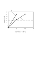
図14は、気温32.5℃、相対湿度85%の高温高湿環境で、記録材PとしてA4サイズの普通紙を搬送する場合である。そして、A4サイズの記録材Pが縦方向に搬送される際の通過幅の端部位置で画像流れが発生し始めるときの印字枚数との関係を示す。 FIG. 14 shows a case where A4-size plain paper is conveyed as the recording material P in a high-temperature and high-humidity environment where the temperature is 32.5 ° C. and the relative humidity is 85%. Then, a relationship with the number of printed sheets when an image flow starts to occur at the end position of the passing width when the A4-sized recording material P is conveyed in the vertical direction is shown.
図14に示すグラフfは、印字時に設定された転写ローラ5に印加する転写バイアス電圧が平均で+2.7kVで、記録材Pの坪量が100g/m2で縦方向と横方向に500枚ずつ交互に搬送した場合である。
A graph f shown in FIG. 14 shows that the transfer bias voltage applied to the
図14に示すグラフgは、印字時に設定された転写ローラ5に印加する転写バイアス電圧が平均で+2.5kVで、記録材Pの坪量が80g/m2で縦方向と横方向に500枚ずつ交互に搬送した場合である。
The graph g shown in FIG. 14 shows that the transfer bias voltage applied to the
図14に示されたように、グラフgは転写ローラ5に印加する転写バイアス電圧が+2.5kVで記録材Pの坪量が80g/m2で、記録材Pを縦方向と横方向に500枚ずつ交互に搬送したグラフである。グラフfは転写ローラ5に印加する転写バイアス電圧が+2.7kVで記録材Pの坪量が100g/m2で、記録材Pを縦方向と横方向に500枚ずつ交互に搬送したグラフである。グラフgよりもグラフfの方が、2分の1の印字枚数で画像流れが発生することが分かる。
As shown in FIG. 14, the graph g shows that the transfer bias voltage applied to the
図14に示すように、例えば、画素低下率(%)が30%の場合では、グラフfは総印字枚数が50000枚程度で到達し、グラフgは総印字枚数が100000枚程度で到達している。 As shown in FIG. 14, for example, when the pixel reduction rate (%) is 30%, the graph f reaches when the total number of printed sheets is about 50,000, and the graph g reaches when the total number of printed sheets is about 100,000. Yes.
これは、A4サイズの記録材Pの通過幅の端部位置に画像が印字される際、紙の坪量に応じて印加される転写バイアス電圧が増加する。これにより、転写ローラ5と、感光ドラム1との間の電界が強くなり記録材Pの紙粉が感光ドラム1の表面に付着し易くなることが原因である。
This is because when the image is printed at the end position of the passage width of the A4 size recording material P, the transfer bias voltage applied according to the basis weight of the paper increases. This is because the electric field between the
そこで、図14に示すグラフf,gに基づいて、印字される平均印字率に応じて、それぞれの記録材Pの通過幅の端部位置で画像流れが発生し始める印字枚数、つまり回復動作を実施するタイミングと動作実施時間を決定する関係式を導いた。 Therefore, based on the graphs f and g shown in FIG. 14, the number of prints at which image flow starts to occur at the end position of the passage width of each recording material P, that is, the recovery operation is determined according to the average print rate to be printed. A relational expression for determining the timing to perform and the operation execution time was derived.
<回復動作実施タイミング>
ここで、回復動作開始閾値(%)を{予想画素低下率α(%)}が15%以上に設定した。また、{目標画素低下率G(%)}を10%に設定した。
<Recovery operation execution timing>
Here, the recovery operation start threshold (%) is set such that the {predicted pixel decrease rate α (%)} is 15% or more. Further, {target pixel reduction rate G (%)} was set to 10%.
予想画素低下率は以下の数41式で示される。 The expected pixel decrease rate is expressed by the following equation (41).
[数41]
{予想画素低下率α(%)}={画素低下率悪化分A(%)}−{画素低下率良化分B(%)}
[Equation 41]
{Expected pixel reduction rate α (%)} = {Pixel reduction rate deterioration A (%)} − {Pixel reduction rate improvement B (%)}
ここで、前記数41式における画素低下率良化分Bとは感光ドラム1の表面上の記録材Pの過去の通過履歴へのキャンセル分とし、それ以降の感光ドラム1の表面上の記録材Pの通過履歴への影響は無いものとする。
Here, the pixel reduction rate improvement B in the equation 41 is the amount of cancellation of the recording material P on the surface of the
回復動作実施時間は以下の数42式で示される。 The recovery operation execution time is expressed by the following equation (42).
[数42]
回復動作実施時間(min)=0.2×[{予想画素低下率α(%)}−{目標画素低下率G(%)}]
[Formula 42]
Recovery operation execution time (min) = 0.2 × [{expected pixel decrease rate α (%)} − {target pixel decrease rate G (%)}]
ここで、{画素低下率悪化分A(%)}は以下の数43式で示される。 Here, {the pixel deterioration rate deterioration A (%)} is expressed by the following equation (43).
[数43]
{画素低下率悪化分A(%)}=7×10⁻⁷×{悪化分の総通過距離(mm)}×(12.5×平均転写バイアス電圧/2.5−11.5)
[Equation 43]
{Pixel decrease rate deterioration A (%)} = 7 × 10 −7 × {Total passage distance (mm) of deterioration} × (12.5 × Average transfer bias voltage / 2.5-11.5)
尚、前記数43式における{悪化分の総通過距離(mm)}は以下の数44式で示される。 In addition, {total passage distance (mm) for deterioration} in the above equation (43) is expressed by the following equation (44).
[数44]
{悪化分の総通過距離(mm)}={各サイズの記録材Pの搬送方向の長さ(mm)}×{そのサイズの記録材Pの枚数}
[Equation 44]
{Total passage distance (mm) for deterioration} = {Length of transporting direction of recording material P of each size (mm)} × {Number of recording materials P of that size}
尚、本実施形態では、基準の転写バイアス電圧を記録材Pが普通紙のときに設定する+2.5kVとした。 In this embodiment, the reference transfer bias voltage is set to +2.5 kV which is set when the recording material P is plain paper.
前記数41式における{画素低下率良化分B(%)}は過去の記録材Pの通過履歴のキャンセル分であって、以下の数45式で示される。 The {pixel reduction rate improvement B (%)} in the equation (41) is a cancellation amount of the past recording history of the recording material P, and is represented by the following equation (45).
[数45]
{画素低下率良化分B(%)}=0.1×[{良化分の総通過距離(mm)}/{悪化分の総通過距離(mm)}]×100
[Equation 45]
{Pixel reduction rate improvement B (%)} = 0.1 × [{Better total passage distance (mm)} / {Deterioration total passage distance (mm)}] × 100
尚、悪化分の記録材Pよりも感光ドラム1の長手方向に幅の広い記録材P1,P2が存在する場合における{良化分の総通過距離(mm)}は以下の数46式で示される。
Note that the {total passage distance (mm) for improvement} in the case where there are recording materials P1 and P2 that are wider in the longitudinal direction of the
[数46]
{良化分の総通過距離(mm)}=[{記録材P1の搬送方向の長さ(mm)}×{記録材P1の枚数}]+[{記録材P2の搬送方向の長さ(mm)}×{記録材P2の枚数}]
[Equation 46]
{Total passage distance for improvement (mm)} = [{length of recording material P1 in conveyance direction (mm)} × {number of recording materials P1}] + [{length of recording material P2 in conveyance direction ( mm)} × {number of recording materials P2}]
例えば、記録材Pが感光ドラム1の表面を通過する際に設定された転写ローラ5に印加する平均転写バイアス電圧が図14のグラフgで示す+2.5kVと、図14のグラフfで示す+2.7kVでは以下のような差が生じる。
For example, the average transfer bias voltage applied to the
<平均転写バイアス電圧が+2.5kVの場合>
例えば、画素低下率悪化分Aの要素としてA4サイズの記録材Pが縦方向(1枚当たりの感光ドラム1の長手方向の通過幅が297mmで搬送方向の通過長さが210mm)が過去の搬送履歴として10万枚通過する。
<When average transfer bias voltage is +2.5 kV>
For example, the A4 size recording material P as the element of the pixel decrease rate deterioration A in the vertical direction (passage width in the longitudinal direction of the
その後、画素低下率良化分Bの要素としてA4サイズの縦方向以上の感光ドラム1の長手方向の通過幅を有するB4サイズの普通紙を搬送方向が長手方向となる横方向が過去の搬送履歴として2万枚通過する。B4サイズの横方向搬送では、1枚当たりの感光ドラム1の長手方向の通過幅が257mmで搬送方向の通過長さが364mmである。
Thereafter, B4 size plain paper having a longitudinal passage width of the
その後、A3サイズの普通紙を搬送方向が長手方向となる横方向(1枚当たりの感光ドラム1の長手方向の通過幅が297mmで搬送方向の通過長さが420mm)が3万枚通過した時点での予想画素低下率α1は以下の数47式から5.3%が求められる。
Thereafter, when 30,000 sheets of A3 size plain paper passes in the horizontal direction (the longitudinal width of the
[数47]
{予想画素低下率α1(%)}={画素低下率悪化分A(%)}−{画素低下率良化分B1(%)}=11.4%
[Equation 47]
{Expected pixel decrease rate α1 (%)} = {Pixel decrease rate deterioration A (%)} − {Pixel decrease rate improvement B1 (%)} = 11.4%
ここで、前記数45式に示される{悪化分の総通過距離(mm)}としては、記録材PとしてA4サイズの普通紙を縦方向(記録材Pの搬送方向が長手方向となる方向)に搬送する。その場合の搬送方向の通過長さが297mmと、過去の搬送履歴として10万枚通過分との積を求める。
Here, as the {total passage distance (mm) for deterioration} shown in the
即ち、前記数3式から{画素低下率悪化分A(%)}は以下の数48式により求められる。
That is, {the pixel deterioration rate deterioration A (%)} is obtained by the following equation 48 from the
[数48]
{画素低下率悪化分A(%)}=7×10−7×297×100000×(12.5×2.5/2.5−11.5)=20.8%
[Formula 48]
{Pixel decrease rate deterioration A (%)} = 7 × 10 −7 × 297 × 100000 × (12.5 × 2.5 / 2.5-11.5) = 20.8%
また、前記数47式に示される{画素低下率良化分B1(%)}は過去の記録材Pの通過履歴のキャンセル分である。{良化分の総通過距離(mm)}としては、記録材PとしてA4サイズの縦方向以上の感光ドラム1の長手方向の通過幅を有するB4サイズの普通紙を横方向に搬送する。その場合の搬送方向の通過長さが364mmと、過去の搬送履歴として2万枚通過分との積を求める。更に、A3サイズの普通紙を横方向に搬送した場合の搬送方向の通過長さが420mmと、過去の搬送履歴として3万枚通過分との積を求め、これらの和を求める。
In addition, {pixel reduction rate improvement B1 (%)} shown in the equation 47 is a cancellation of the past recording history of the recording material P. As the total pass distance (mm) for the improvement, B4 size plain paper having a longitudinal passage width of the
{悪化分の総通過距離(mm)}としては、記録材PとしてA4サイズの普通紙を縦方向に搬送した場合の搬送方向の通過長さが210mmと、過去の搬送履歴として10万枚通過分との積を求める。 As for {total passage distance (mm) for deterioration}, the length of passage in the transport direction when transporting A4-size plain paper as the recording material P in the vertical direction is 210 mm, and the past transport history passes 100,000 sheets. Find the product of minutes.
これらを用いて{画素低下率良化分B1(%)}は以下の数49式により求められる。 Using these, {pixel reduction rate improvement B1 (%)} is obtained by the following equation (49).
[数49]
{画素低下率良化分B1(%)}=0.1×[{(364×20000)+(420×30000)}/(210×100000)]×100≒9.4%
[Equation 49]
{Pixel reduction rate improvement B1 (%)} = 0.1 × [{(364 × 20000) + (420 × 30000)} / (210 × 100000)] × 100≈9.4%
<平均転写バイアス電圧が+2.7kVの場合>
例えば、画素低下率悪化分Aの要素としてA4サイズの記録材Pが縦方向(1枚当たりの感光ドラム1の長手方向の通過幅が297mmで搬送方向の通過長さが210mm)が過去の搬送履歴として5万枚通過する。
<When the average transfer bias voltage is +2.7 kV>
For example, the A4 size recording material P as the element of the pixel decrease rate deterioration A in the vertical direction (passage width in the longitudinal direction of the
その後、画素低下率良化分Bの要素としてA4サイズの縦方向以上の感光ドラム1の長手方向の通過幅を有するB4サイズの普通紙を搬送方向が長手方向となる横方向が過去の搬送履歴として2万枚通過する。B4サイズの横方向搬送では、1枚当たりの感光ドラム1の長手方向の通過幅が257mmで搬送方向の通過長さが364mmである。
Thereafter, B4 size plain paper having a longitudinal passage width of the
その後、A3サイズの普通紙を搬送方向が長手方向となる横方向(1枚当たりの感光ドラム1の長手方向の通過幅が297mmで搬送方向の通過長さが420mm)が3万枚通過した時点での予想画素低下率α2は以下の数50式から−4.2%が求められる。
Thereafter, when 30,000 sheets of A3 size plain paper passes in the horizontal direction (the longitudinal width of the
[数50]
{予想画素低下率α2(%)}={画素低下率悪化分A(%)}−{画素低下率良化分B1(%)}=1.9%
[Equation 50]
{Expected pixel reduction rate α2 (%)} = {Pixel reduction rate deterioration A (%)} − {Pixel reduction rate improvement B1 (%)} = 1.9%
ここで、前記数45式に示される{悪化分の総通過距離(mm)}としては、記録材PとしてA4サイズの普通紙を縦方向(記録材Pの搬送方向が長手方向となる方向)に搬送する。その場合の搬送方向の通過長さが297mmと、過去の搬送履歴として5万枚通過分との積を求める。
Here, as the {total passage distance (mm) for deterioration} shown in the
そして、前記数3式から{画素低下率悪化分A(%)}は以下の数51式により求められる。 Then, {pixel deterioration rate deterioration A (%)} is obtained from the following equation (51) from the above equation (3).
[数51]
{画素低下率悪化分A(%)}=7×10−7×297×50000×(12.5×2.7/2.5−11.5)=20.8%
[Formula 51]
{Pixel decrease rate deterioration A (%)} = 7 × 10 −7 × 297 × 50000 × (12.5 × 2.7 / 2.5-11.5) = 20.8%
また、前記数50式に示される{画素低下率良化分B1(%)}は過去の記録材Pの通過履歴のキャンセル分である。{良化分の総通過距離(mm)}としては、記録材PとしてA4サイズの縦方向以上の感光ドラム1の長手方向の通過幅を有するB4サイズの普通紙を横方向に搬送する。その場合の搬送方向の通過長さが364mmと、過去の搬送履歴として2万枚通過分との積を求める。
Further, {pixel reduction rate improvement B1 (%)} shown in the
更に、A3サイズの普通紙を横方向に搬送した場合の搬送方向の通過長さが420mmと、過去の搬送履歴として3万枚通過分tの積を求め、それらの和を求める。 Further, the product of the passage length in the transport direction when the A3 size plain paper is transported in the horizontal direction is 420 mm, and the passage t of 30,000 sheets is obtained as the past transport history, and the sum thereof is obtained.
{悪化分の総通過距離(mm)}としては、記録材PとしてA4サイズの普通紙を縦方向に搬送した場合の搬送方向の通過長さが210mmと、過去の搬送履歴として5万枚通過分との積を求める。 As for {total passage distance (mm) for deterioration}, the passing length in the transport direction when transporting A4 size plain paper as the recording material P in the vertical direction is 210 mm, and 50,000 sheets have passed as the past transport history Find the product of minutes.
これらを用いて{画素低下率良化分B1(%)}は以下の数52式により求められる。 Using these, {pixel reduction rate improvement B1 (%)} is obtained by the following equation (52).
[数52]
{画素低下率良化分B1(%)}=0.1×[{(364×20000)+(420×30000)}/(210×50000)]×100≒18.9%
[Formula 52]
{Pixel reduction rate improvement B1 (%)} = 0.1 × [{(364 × 20000) + (420 × 30000)} / (210 × 50000)] × 100≈18.9%
これにより、A4サイズの記録材Pを縦方向に搬送する。そして、図14のグラフgに示す平均の転写バイアス電圧を+2.5kVに設定して記録材Pを10万枚搬送する。これと比べて、図14のグラフfに示す平均の転写バイアス電圧を+2.7kVに設定した場合は半分の5万枚の記録材Pを搬送した時点で同等の予想画素低下率となってしまうことが分かる。 Thereby, the A4-sized recording material P is conveyed in the vertical direction. Then, the average transfer bias voltage shown in the graph g of FIG. 14 is set to +2.5 kV, and 100,000 recording materials P are conveyed. Compared with this, when the average transfer bias voltage shown in the graph f in FIG. 14 is set to +2.7 kV, the same expected pixel reduction rate is obtained when half of the recording material P is conveyed. I understand that.
この予想画素低下率によって求められた回復動作実施時間により決定されるクリーニング動作を実施することで画素低下率は目標画素低下率の10%まで低下する。初回のクリーニング動作が実施された際、メモリ18にクリーニング動作実施履歴を記憶させ、クリーニング動作を実施した以降に印字した記録材Pのサイズや枚数、印字されたサイズ毎の順番等を随時記憶していく。そして、二回目以降のクリーニング動作を実施した際の予想画素低下率βは前記第1実施形態と同様に以下のように算出する。
By performing the cleaning operation determined by the recovery operation execution time obtained from the predicted pixel decrease rate, the pixel decrease rate is reduced to 10% of the target pixel decrease rate. When the first cleaning operation is performed, the cleaning operation execution history is stored in the
<二回目以降のクリーニング動作を実施した際の予想画素低下率β>
ここで、回復動作開始閾値(%)を{予想画素低下率β(%)}が15%以上に設定した。また、{目標画素低下率G(%)}を10%に設定した。
<Expected pixel reduction rate β when the second and subsequent cleaning operations are performed>
Here, the recovery operation start threshold (%) is set such that the {predicted pixel decrease rate β (%)} is 15% or more. Further, {target pixel reduction rate G (%)} was set to 10%.
二回目以降のクリーニング動作を実施した際の{予想画素低下率β(%)}は以下の数53式により求められる。 The {predicted pixel reduction rate β (%)} when the second and subsequent cleaning operations are performed is obtained by the following equation (53).
[数53]
{予想画素低下率β(%)}={回復動作実施後の画素低下率が10%}+{画素低下率悪化分A´(%)}−{画素低下率良化分B´(%)}
[Formula 53]
{Expected pixel decrease rate β (%)} = {Pixel decrease rate after recovery operation is 10%} + {Pixel decrease rate deterioration A ′ (%)} − {Pixel decrease rate improvement B ′ (%) }
ここで、{画素低下率良化分B´}とは、直前のクリーニング動作を実施した後で、且つ、過去の記録材Pの通過履歴へのキャンセル分として、それ以降の記録材Pの通過履歴への影響は無いものとする。 Here, {the pixel reduction rate improving portion B ′} is the passage of the recording material P after the previous cleaning operation and as the amount of cancellation to the past recording material P passing history. There is no impact on the history.
<回復動作実施時間>
{回復動作実施時間(min)}は以下の数54式により求められる。
<Recovery operation time>
{Recovery operation execution time (min)} is obtained by the following equation (54).
[数54]
{回復動作実施時間(min)}=0.2×[{予想画素低下率β(%)}−{目標画素低下率G(%)}]
[Formula 54]
{Recovery operation execution time (min)} = 0.2 × [{Expected pixel decrease rate β (%)} − {Target pixel decrease rate G (%)}]
ここで、{画素低下率悪化分A´(%)}は以下の数55式で示される。
Here, {the pixel deterioration rate deterioration A ′ (%)} is expressed by the following
[数55]
{画素低下率悪化分A´(%)}=7×10⁻⁷×{悪化分の総通過距離(mm)}×(12.5×平均転写バイアス電圧/2.5−11.5)
[Equation 55]
{Pixel decrease rate deterioration A ′ (%)} = 7 × 10 −7 × {Total passage distance (mm) for deterioration} × (12.5 × Average transfer bias voltage / 2.5-11.5)
尚、前記数55式における{悪化分の総通過距離(mm)}は以下の数56式で示される。
The {total passage distance (mm) for deterioration} in the
[数56]
{悪化分の総通過距離(mm)}=各サイズの記録材Pの搬送方向の長さ(mm)×そのサイズの記録材Pの枚数
[Formula 56]
{Total passage distance (mm) for deterioration} = Length (mm) in the conveyance direction of the recording material P of each size × Number of recording materials P of that size
尚、前記数53式における{画素低下率良化分B´(%)}は過去の記録材Pの通過履歴のキャンセル分であって、以下の数57式で示される。 Note that {Pixel reduction rate improvement B ′ (%)} in the equation 53 is the amount of cancellation of the past recording material P passing history, and is expressed by the following equation 57.
[数57]
{画素低下率良化分B´(%)}=0.1×[{良化分の総通過距離(mm)}/{悪化分の総通過距離(mm)}]×100
[Equation 57]
{Pixel reduction rate improvement B ′ (%)} = 0.1 × [{Total passage distance (mm) for improvement} / {Total passage distance (mm) for deterioration]] × 100
尚、悪化分の記録材Pよりも感光ドラム1の長手方向に幅の広い記録材P1,P2が存在する場合における{良化分の総通過距離(mm)}は以下の数58式で示される。
Note that the {total passage distance (mm) for improvement} in the case where there are recording materials P1 and P2 that are wider in the longitudinal direction of the
[数58]
{良化分の総通過距離(mm)}=[{記録材P1の搬送方向の長さ(mm)}×{記録材P1の枚数}]+[{記録材P2の搬送方向の長さ(mm)}×{記録材P2の枚数}]
[Formula 58]
{Total passage distance for improvement (mm)} = [{length of recording material P1 in conveyance direction (mm)} × {number of recording materials P1}] + [{length of recording material P2 in conveyance direction ( mm)} × {number of recording materials P2}]
上記のように決定された回復動作実施時間の通りに実施されるクリーニング動作については前記第1実施形態と同様である。 The cleaning operation performed according to the recovery operation execution time determined as described above is the same as that in the first embodiment.
本実施形態によれば、印字される記録材Pのサイズや枚数、紙の坪量(印加される転写バイアス電圧)の各種情報に応じて、精度よく画像流れ等の画像不良の最悪レベルを予測・算出する。その値によって回復動作(クリーニング動作)のタイミングや回復動作実施時間を調整する。 According to this embodiment, the worst level of image defects such as image flow can be accurately predicted according to various types of information such as the size and number of recording materials P to be printed and the basis weight of paper (applied transfer bias voltage). ·calculate. The timing of the recovery operation (cleaning operation) and the recovery operation execution time are adjusted according to the value.
これにより、最適な回復動作実施タイミングと回復動作実施時間で感光ドラム1の寿命短縮を防止する。更に、クリーニング装置6の耐久性の低下を防止する。更に、別途、ヒータを設けることによるコスト高を伴うことがなく、画像流れ等の画像不良を防止して長期に渡って良好な画像が得られる。
Thus, the life of the
P,P1,P2 …記録材
1 …感光ドラム(像担持体)
6 …クリーニング装置(クリーニング手段)
17 …CPU(制御手段;判断手段;積算長さ算出手段;第二の積算長さ算出手段;絶対湿度算出手段)
18 …メモリ(記録材情報記憶手段;画像情報記憶手段;転写バイアス電圧情報記憶手段;印字率情報記憶手段;記憶手段)
P, P1, P2 ...
6 ... Cleaning device (cleaning means)
17 ... CPU (control means; judgment means; integrated length calculation means; second integrated length calculation means; absolute humidity calculation means)
18 Memory (recording material information storage means; image information storage means; transfer bias voltage information storage means; printing rate information storage means; storage means)
Claims (5)
所定サイズの記録シートが前記ニップ部を通過する時の前記所定サイズの記録シートの搬送方向における長さの積算長さから、前記所定サイズの記録シートを越えるサイズのシートが前記ニップ部を通過する時の前記越えるサイズのシートの搬送方向における長さの積算長さを除いた値に基づいて前記像担持体の状態変化を判定する判定手段と、
を有することを特徴とする画像形成装置。 A transfer means for transferring an image formed on the image carrier to a recording sheet that is nipped and conveyed through a nip formed between the image carrier and the image carrier;
A sheet having a size exceeding the recording sheet of the predetermined size passes through the nip portion based on an accumulated length of the recording sheet of the predetermined size in the conveying direction when the recording sheet of the predetermined size passes through the nip portion. Determination means for determining a change in state of the image carrier based on a value excluding an accumulated length of the length in the conveyance direction of the sheet of the size exceeding the time ;
An image forming apparatus comprising:
前記判定手段は、前記像担持体の状態変化の判定に、前記転写バイアス電圧取得手段が取得した転写バイアス電圧を加味して判定することを特徴とする請求項1〜3のいずれか1項に記載の画像形成装置。 Transfer bias voltage acquisition means for acquiring a transfer bias voltage applied to the transfer means;
Said determining means to determine the state change of the image bearing member, to any one of claims 1 to 3, wherein the determining in consideration of the transfer bias voltage, wherein the transfer bias voltage acquisition unit acquires The image forming apparatus described.
所定サイズの記録シートが前記ニップ部を通過する時の通過量から前記所定サイズの記録シートを越えるサイズのシートが前記ニップ部を通過する時の通過量を除いた値に基づいて、前記像担持体に対する所定のクリーニング動作を行うクリーニング手段と、
を有することを特徴とする画像形成装置。 A transfer means for transferring an image formed on the image carrier to a recording sheet that is nipped and conveyed through a nip formed between the image carrier and the image carrier;
Based on the value sheet size exceeding the recording sheet from passing amount predetermined size excluding the passage amount when passing through the nip portion when a predetermined size recording sheet passes through the nip portion, the image bearing Cleaning means for performing a predetermined cleaning operation on the body;
An image forming apparatus comprising:
Priority Applications (1)
| Application Number | Priority Date | Filing Date | Title |
|---|---|---|---|
| JP2013095667A JP6235233B2 (en) | 2013-04-30 | 2013-04-30 | Image forming apparatus |
Applications Claiming Priority (1)
| Application Number | Priority Date | Filing Date | Title |
|---|---|---|---|
| JP2013095667A JP6235233B2 (en) | 2013-04-30 | 2013-04-30 | Image forming apparatus |
Publications (3)
| Publication Number | Publication Date |
|---|---|
| JP2014215598A JP2014215598A (en) | 2014-11-17 |
| JP2014215598A5 JP2014215598A5 (en) | 2016-06-23 |
| JP6235233B2 true JP6235233B2 (en) | 2017-11-22 |
Family
ID=51941361
Family Applications (1)
| Application Number | Title | Priority Date | Filing Date |
|---|---|---|---|
| JP2013095667A Active JP6235233B2 (en) | 2013-04-30 | 2013-04-30 | Image forming apparatus |
Country Status (1)
| Country | Link |
|---|---|
| JP (1) | JP6235233B2 (en) |
Families Citing this family (6)
| Publication number | Priority date | Publication date | Assignee | Title |
|---|---|---|---|---|
| JP6330722B2 (en) * | 2015-05-13 | 2018-05-30 | コニカミノルタ株式会社 | Image forming apparatus and image forming system |
| EP3112943B1 (en) | 2015-06-30 | 2020-08-26 | Canon Kabushiki Kaisha | Image forming apparatus, image forming system and fixing device |
| JP6192684B2 (en) * | 2015-06-30 | 2017-09-06 | キヤノン株式会社 | Image forming apparatus and image forming system |
| JP6192685B2 (en) * | 2015-06-30 | 2017-09-06 | キヤノン株式会社 | Image forming apparatus |
| JP6113230B2 (en) * | 2015-06-30 | 2017-04-12 | キヤノン株式会社 | Image forming apparatus and fixing device |
| JP6516620B2 (en) * | 2015-07-31 | 2019-05-22 | キヤノン株式会社 | Image forming apparatus and image forming system |
Family Cites Families (6)
| Publication number | Priority date | Publication date | Assignee | Title |
|---|---|---|---|---|
| JPH11249501A (en) * | 1998-02-27 | 1999-09-17 | Canon Inc | Image forming device and processing cartridge |
| JP2000039819A (en) * | 1998-07-22 | 2000-02-08 | Canon Inc | Image forming device |
| JP2001154430A (en) * | 1999-11-25 | 2001-06-08 | Seiko Epson Corp | Device and method for forming image |
| JP2002258683A (en) * | 2001-03-05 | 2002-09-11 | Murata Mach Ltd | Image recording device |
| JP2004361726A (en) * | 2003-06-05 | 2004-12-24 | Kyocera Mita Corp | Image forming apparatus |
| JP2005031384A (en) * | 2003-07-11 | 2005-02-03 | Kyocera Mita Corp | Image forming apparatus |
-
2013
- 2013-04-30 JP JP2013095667A patent/JP6235233B2/en active Active
Also Published As
| Publication number | Publication date |
|---|---|
| JP2014215598A (en) | 2014-11-17 |
Similar Documents
| Publication | Publication Date | Title |
|---|---|---|
| JP5741656B2 (en) | Image forming apparatus and image forming program | |
| JP6235233B2 (en) | Image forming apparatus | |
| JP6225824B2 (en) | Image forming apparatus and control method thereof | |
| JP5487134B2 (en) | Image forming apparatus | |
| JP2000039819A (en) | Image forming device | |
| JP2011013595A (en) | Image forming apparatus | |
| JP2009122241A (en) | Image forming apparatus and cleaning method for image forming apparatus | |
| JP6159692B2 (en) | Image forming apparatus | |
| JP2009192568A (en) | Image forming apparatus, and control program for image forming processing | |
| JP6531734B2 (en) | Image forming device | |
| JP6221976B2 (en) | Image forming apparatus | |
| JP6098454B2 (en) | Image forming apparatus | |
| JP2017054090A (en) | Image forming apparatus and control method of image forming apparatus | |
| JP4731978B2 (en) | Image forming apparatus | |
| JP6475149B2 (en) | Image forming apparatus | |
| JP6407046B2 (en) | Image forming apparatus | |
| JP6561933B2 (en) | Image forming apparatus | |
| JP7224820B2 (en) | image forming device | |
| JP2013020024A (en) | Image forming apparatus | |
| JP2010020246A (en) | Image forming apparatus | |
| JP2018132571A (en) | Image formation device | |
| JP2008309973A (en) | Image forming apparatus | |
| JP6627797B2 (en) | Image forming device | |
| JP6490568B2 (en) | Image forming apparatus | |
| JP6465062B2 (en) | Image forming apparatus |
Legal Events
| Date | Code | Title | Description |
|---|---|---|---|
| A521 | Request for written amendment filed |
Free format text: JAPANESE INTERMEDIATE CODE: A523 Effective date: 20160428 |
|
| A621 | Written request for application examination |
Free format text: JAPANESE INTERMEDIATE CODE: A621 Effective date: 20160428 |
|
| A977 | Report on retrieval |
Free format text: JAPANESE INTERMEDIATE CODE: A971007 Effective date: 20170118 |
|
| A131 | Notification of reasons for refusal |
Free format text: JAPANESE INTERMEDIATE CODE: A131 Effective date: 20170124 |
|
| A521 | Request for written amendment filed |
Free format text: JAPANESE INTERMEDIATE CODE: A523 Effective date: 20170310 |
|
| A131 | Notification of reasons for refusal |
Free format text: JAPANESE INTERMEDIATE CODE: A131 Effective date: 20170718 |
|
| A521 | Request for written amendment filed |
Free format text: JAPANESE INTERMEDIATE CODE: A523 Effective date: 20170830 |
|
| TRDD | Decision of grant or rejection written | ||
| A01 | Written decision to grant a patent or to grant a registration (utility model) |
Free format text: JAPANESE INTERMEDIATE CODE: A01 Effective date: 20171003 |
|
| A61 | First payment of annual fees (during grant procedure) |
Free format text: JAPANESE INTERMEDIATE CODE: A61 Effective date: 20171026 |
|
| R150 | Certificate of patent or registration of utility model |
Ref document number: 6235233 Country of ref document: JP Free format text: JAPANESE INTERMEDIATE CODE: R150 |
|
| R250 | Receipt of annual fees |
Free format text: JAPANESE INTERMEDIATE CODE: R250 |
|
| R250 | Receipt of annual fees |
Free format text: JAPANESE INTERMEDIATE CODE: R250 |
|
| R250 | Receipt of annual fees |
Free format text: JAPANESE INTERMEDIATE CODE: R250 |
|
| R250 | Receipt of annual fees |
Free format text: JAPANESE INTERMEDIATE CODE: R250 |
|
| R250 | Receipt of annual fees |
Free format text: JAPANESE INTERMEDIATE CODE: R250 |