JP6318641B2 - Droplet discharge device, degassing method, nozzle cleaning method, and image forming apparatus - Google Patents
Droplet discharge device, degassing method, nozzle cleaning method, and image forming apparatus Download PDFInfo
- Publication number
- JP6318641B2 JP6318641B2 JP2014010425A JP2014010425A JP6318641B2 JP 6318641 B2 JP6318641 B2 JP 6318641B2 JP 2014010425 A JP2014010425 A JP 2014010425A JP 2014010425 A JP2014010425 A JP 2014010425A JP 6318641 B2 JP6318641 B2 JP 6318641B2
- Authority
- JP
- Japan
- Prior art keywords
- path
- liquid
- ink
- droplet discharge
- valve
- Prior art date
- Legal status (The legal status is an assumption and is not a legal conclusion. Google has not performed a legal analysis and makes no representation as to the accuracy of the status listed.)
- Expired - Fee Related
Links
Images


Description
本発明は、インク、その他の液体を吐出する液滴吐出装置、液体からの脱気方法、ノズルの洗浄方法、及び画像形成装置に関する。 The present invention relates to a droplet discharge device that discharges ink and other liquids, a degassing method from a liquid, a nozzle cleaning method, and an image forming apparatus.
インクジェット方式の液滴吐出装置を利用して記録を行うプリンタ等の画像形成装置において、吐出ヘッド(インクジェットヘッド)に目詰りが発生すると、吐出ヘッド内のノズルからインクが吐出されず、正しく画像記録することができなくなる。
吐出ヘッドが目詰まりを起こす原因として、インク内に気泡が混入することと、ノズル部にインクの固体成分が固着することが知られている。
インク内に気泡が混入するとノズルに気泡が詰まり、インクの吐出が妨げられる。
In an image forming apparatus such as a printer that performs recording using an ink jet type droplet discharge device, if the discharge head (ink jet head) is clogged, ink is not discharged from the nozzles in the discharge head and the image is recorded correctly. Can not do.
As a cause of clogging of the discharge head, it is known that bubbles are mixed in the ink and that the solid component of the ink is fixed to the nozzle portion.
When bubbles are mixed in the ink, the nozzles are clogged and the ejection of ink is hindered.
また、固体成分が分離しやすいインクを用いる場合、吐出ヘッドにインクを供給する流路中のインクが流動しない状態が続くと、インク中の固体成分が沈殿してノズルを塞ぎ、インクの吐出が妨げられる。
さらに、ノズル内のインクが乾燥すると、インク中の固体成分がノズルを塞ぎ、インクの吐出が妨げられる。
インク中の気泡を除去する手段としては、特許文献1(特許第5209431号)のインクジェット装置に開示された気体を透過させる部材を用いた脱気装置が用いられる。
この脱気装置では、脱気室内に配置された気体を透過させる部材により、インク室と気体室とに分離された構造になっている。インク室にインクを流し、気体室を減圧すると、インク室内のインクに溶け込んだ気体が気体を透過させる部材を経由して気体室に移動し、インク内が脱気される仕組みになっている。
In addition, when ink that easily separates the solid component is used, if the ink in the flow path for supplying ink to the discharge head does not flow continuously, the solid component in the ink precipitates and closes the nozzle, and the ink is discharged. Be disturbed.
Furthermore, when the ink in the nozzles is dried, solid components in the ink block the nozzles, thereby preventing ink ejection.
As a means for removing bubbles in the ink, a deaeration device using a gas permeable member disclosed in an ink jet device disclosed in Patent Document 1 (Patent No. 5209431) is used.
This deaeration device has a structure in which an ink chamber and a gas chamber are separated by a member that transmits gas disposed in the deaeration chamber. When ink is flowed into the ink chamber and the gas chamber is depressurized, the gas dissolved in the ink in the ink chamber moves to the gas chamber via a member that allows the gas to pass through, and the inside of the ink is deaerated.
ところで、気体を透過させる部材を用いた脱気装置を用いてインクを脱気する場合に、脱気装置にインクが十分に流入しなくなった状態で気体室を減圧すると、インク室内のインクが過剰に減圧されることになる。この場合、インクを構成する溶媒が気体室に移動し、インク室内のインク濃度が上昇する。その結果、インクの粘度が上昇して吐出ヘッドでの吐出不良が発生する。そのため、脱気装置を用いて脱気する場合には、脱気装置に対してインクをある程度の流量で流し続ける必要がある。その手法の一つとして特許文献1には、ポンプを用いて脱気装置に一定流量のインクを流し続ける手法が開示されている。
これによれば、吐出ヘッド周辺のインク流路内にインクが常に循環するため、インク中の固体成分が沈殿することも同時に防ぐことができる。
By the way, when ink is deaerated using a deaeration device using a gas-permeable member, if the gas chamber is decompressed in a state where ink does not sufficiently flow into the deaeration device, the ink in the ink chamber is excessive. Will be decompressed. In this case, the solvent constituting the ink moves to the gas chamber, and the ink concentration in the ink chamber increases. As a result, the viscosity of the ink rises and discharge failure occurs at the discharge head. For this reason, when deaeration is performed using a deaeration device, it is necessary to keep ink flowing at a certain flow rate through the deaeration device. As one of the methods,
According to this, since the ink always circulates in the ink flow path around the ejection head, it is possible to prevent the solid component in the ink from being precipitated at the same time.
次に、ノズル部に付着、残留したインクの固形成分を取り除くため、吐出ヘッドに洗浄液を流す手法として特許文献2の手法が知られている。
特許文献2に開示されたインクジェット装置では、ヘッド内の流路に洗浄液を高圧で流せる構成になっているため、ノズル部で固化したインク成分を洗い流すことができる。
特許文献2に示されたインクジェット装置の構成を改良することにより、サブタンクからメインタンクへポンプでインクを戻す流路途中に脱気装置を取り付ける構成も考えうる。しかし、脱気装置とヘッドとの間に配置されたインクタンクが空気と接しているため、インクタンク内でインクに空気が溶け込むことになる。このため、特許文献2のインクジェット装置によって気泡によるヘッドの目詰まりの発生を防止することは困難である。
Next, a technique of
The ink jet device disclosed in
A configuration in which a deaeration device is attached in the middle of a flow path for returning ink from the sub tank to the main tank by a pump by improving the configuration of the ink jet device disclosed in
また、特許文献1に示されたインクジェット装置のようにポンプで液体を移動させる構成では、特許文献2のように空圧で液体を加圧して移動させる場合と比べ、洗浄液を十分な圧力で押し出すことができず、ノズルに固着したインクの固体成分を充分に取り除くことができない。
また、液体を移動させるためのポンプは、液体をせき止める機構を有するものが多い。そのため、加圧された液体をポンプに通そうとすると、ポンプ内の液体をせき止める機構と干渉し、ポンプが破損するおそれがある。
以上のように従来技術では、ポンプを用いてインクを循環、及び脱気させる構成と、洗浄液を空圧で加圧して押し出すことによりヘッド内を洗浄する構成とを両立させることが困難であった。
Further, in the configuration in which the liquid is moved by a pump as in the ink jet apparatus disclosed in
Moreover, many pumps for moving liquid have a mechanism for clogging the liquid. Therefore, when trying to pass the pressurized liquid through the pump, it interferes with a mechanism for blocking the liquid in the pump, and the pump may be damaged.
As described above, in the conventional technology, it is difficult to achieve both a configuration in which ink is circulated and degassed using a pump and a configuration in which the inside of the head is cleaned by pressurizing and ejecting the cleaning liquid with air pressure. .
本発明は上記の問題に鑑みてなされたものであり、インク等の液体中の気泡、及び固体成分の沈殿によるノズルの目詰まりを防止する機構と、液体の乾燥によるノズル目詰まりを解消する機構と、を兼ね備えた液滴吐出装置、脱気方法、ノズルの洗浄方法、及び画像形成装置を提供することを目的とする。 The present invention has been made in view of the above problems, and a mechanism for preventing clogging of nozzles due to bubbles in liquid such as ink and precipitation of solid components, and a mechanism for eliminating nozzle clogging due to drying of liquids A droplet discharge device, a deaeration method, a nozzle cleaning method, and an image forming apparatus.
上記目的を達成するため、本発明の液滴吐出装置は、液滴を吐出するノズルを有する液滴吐出部と、前記液滴吐出部に液体を供給するための第1の経路、及び第2の経路と、前記第1の経路を介して前記液滴吐出部に第1の液体を供給する第1の液体供給部と、前記第1の経路に対して第1の切り替え弁を介してつながると共に、前記第2の経路に対して第2の切り替え弁を介してつながり、且つ前記液滴吐出部を迂回する第3の経路と、前記第3の経路上に配置された液体循環手段と、前記第1の経路、若しくは前記第2の経路と、第3の切り替え弁を介してつながる第4の経路と、前記第4の経路を介して前記液滴吐出部に第2の液体を供給する第2の液体供給部と、前記第1の経路、若しくは前記第2の経路中の液体を前記液滴吐出部へ流すために前記第1の経路、若しくは前記第2の経路上に設置された経路開閉手段と、を備えていることを特徴とする。 In order to achieve the above object, a droplet discharge device of the present invention includes a droplet discharge unit having a nozzle for discharging a droplet, a first path for supplying liquid to the droplet discharge unit, and a second channel. And a first liquid supply unit that supplies the first liquid to the droplet discharge unit via the first path, and a first switching valve connected to the first path. And a third path that is connected to the second path via a second switching valve and bypasses the droplet discharge section, and a liquid circulation means disposed on the third path, A second liquid is supplied to the droplet discharge section via the first path or the second path, a fourth path connected via a third switching valve, and the fourth path. A second liquid supply section, and the liquid in the first path or the second path is discharged into the droplet discharge section. It said first path to flow, or characterized in that it and a path switching means disposed on said second path.
本発明によれば、液滴吐出部、及びその周囲の流路中の液体を循環するための循環経路内にフィルタ等の異物除去手段を配置することにより、循環中に液体中に発生した沈殿物によるノズルの目詰まりを防止できる。また、洗浄液で液滴吐出部を洗浄できるため、ノズル部に固着した液体の固体成分を取り除き、ノズルの目詰まりを解消できる。
つまり、液体中の気泡、及び固体成分の沈殿によるノズルの目詰まりを防止する機構と、液体の乾燥によるノズル目詰まりを解消する機構と、を兼ね備えた液滴吐出装置を提供することができる。
According to the present invention, the foreign matter removing means such as a filter is disposed in the circulation path for circulating the liquid in the droplet discharge section and the flow path around the droplet discharge section, so that the precipitate generated in the liquid during the circulation. It is possible to prevent clogging of the nozzle due to objects. In addition, since the droplet discharge portion can be cleaned with the cleaning liquid, the solid component of the liquid fixed to the nozzle portion can be removed, and clogging of the nozzle can be eliminated.
That is, it is possible to provide a droplet discharge device that has both a mechanism for preventing clogging of nozzles due to bubbles in liquid and precipitation of solid components, and a mechanism for eliminating nozzle clogging due to drying of liquids.
以下、本発明を図面に示した実施の形態により詳細に説明する。
《第1の実施形態》
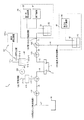
図1は、本発明の第1の実施形態に係る液滴吐出装置(インクジェット装置)の構成を示す略図である。
液滴吐出装置1は、インク等の液滴を吐出するノズル3、及び吐出機構を有するヘッド(液滴吐出部)2と、ヘッド2に液体(第1の液体、第2の液体)を供給するための第1のインク供給経路(第1の経路)100と、ヘッド2に液体(第1の液体、第2の液体)を供給するための第2のインク供給経路(第2の経路)110と、第1のインク供給経路100を介してヘッド2にインク(第1の液体)22を供給するインクタンク(第1の液体貯留部)21を備えた第1の液体供給部20と、第1のインク供給経路100、及び第2のインク供給経路110に対してバルブA(第1の切り替え弁101)及びバルブB(第2の切り替え弁111)を介して夫々つながり、且つヘッド2を迂回する循環経路(第3の経路)120と、循環経路120上に配置された脱気装置121(脱気手段121a+真空発生装置(ポンプ)121b)、及び液体循環手段(ポンプ)122と、第1のインク供給経路100、若しくは第2のインク供給経路110に対してバルブC(第3の切り替え弁102)を介してつながる洗浄液供給経路(第4の経路)130と、洗浄液供給経路130を介してヘッドに洗浄液42(第2の液体)を供給する洗浄液タンク41を備えた第2の液体供給部40と、第1のインク供給経路100、若しくは第2のインク供給経路110中の液体をヘッドへ流すために第1のインク供給経路100、若しくは第2のインク供給経路110上に設置されたバルブD(経路開閉手段112)と、を備える。
ヘッド(液滴吐出部)2は、先端面にインク(第1の液体)22を吐出する微細なノズル3を複数備え、その内部にはノズルと連通し、且つインクを保持する図示しない液室を備えている。また、ヘッド2の異なった部位には、液室にインクや洗浄液を出し入れするための第1の供給口5と第2の供給口6が夫々配置されている。第1の供給口5は第1のインク供給経路100の一端と連通接続され、第2の供給口6は第2のインク供給経路110の一端と連通接続されている。
Hereinafter, the present invention will be described in detail with reference to embodiments shown in the drawings.
First Embodiment
FIG. 1 is a schematic diagram showing a configuration of a droplet discharge device (inkjet device) according to a first embodiment of the present invention.
The
The head (droplet discharge unit) 2 includes a plurality of
ノズル3からインクを液滴として吐出する方式(液滴吐出機構)として、インクを加熱して押し出す方式や、ヘッド内部に配置したピエゾ素子に電圧を加えて変形させることでインクを押し出す方式などが挙げられる。
図示しない印刷対象に対してインクを吐出しつつ、図示しない移動手段を用いてヘッドと印刷対象を相対的に移動させることで、印刷対象に対して印刷することができる。印刷対象として、紙などシート状のものが挙げられる。
なお、液滴吐出装置1から突出される液体は、インクに限らず、印刷、画像形成以外の各種用途に使用される液体を含むものである。
図示しない移動手段として、モータ制御で印刷対象を前後左右に移動させる移動ステージなどが挙げられる。
As a method for ejecting ink as droplets from the nozzle 3 (droplet ejection mechanism), there are a method in which ink is heated and pushed out, a method in which ink is pushed out by applying a voltage to a piezo element arranged inside the head, and the like. Can be mentioned.
Printing can be performed on a print target by relatively moving the head and the print target using a moving unit (not shown) while ejecting ink to the print target (not shown). Examples of the print target include sheet-like materials such as paper.
The liquid protruding from the
Examples of the moving means (not shown) include a moving stage that moves the printing object in the front-rear and left-right directions by motor control.
第1のインク供給経路(第1の経路)100は、一端がヘッドの第1の供給口5につながり、他端がインクタンク21内のインク22に通じており、3つの流路r1、r2、r3から構成されている。
洗浄液供給経路(第4の経路)130は、一端がバルブCにつながり、他端が洗浄液タンク41内の洗浄液42に通じている流路r4から構成されている。
バルブA(第1の切り替え弁101)、バルブB(第2の切り替え弁111)、バルブC(第3の切り替え弁102)は、それぞれ3方の経路に連通接続され、3方の経路のうちのいずれか2方を同時に導通(連通)させる機能を有する。即ち、バルブAは第1のインク供給経路100の途中に配置されると共に、循環経路120の一端と接続されている。バルブBは第2のインク供給経路110の途中に配置されると共に、循環経路120の他端と接続されている。バルブCは、バルブAよりもインクタンク21寄りの第1のインク供給経路100の途中に配置されると共に、洗浄液供給経路130の一端(下流側端部)と接続されている。
バルブD(経路開閉手段112)は、バルブBよりも廃液タンク50寄りの第2のインク供給経路110の途中に配置されており、第2のインク供給経路110を開閉させて大気との連通状態を断接(遮断、接続)する機能を有する。
バルブA、バルブB、バルブC、バルブDによる経路間の接続パターン(開閉パターン)を切り替える方式として、手動式、空圧式、電磁式が挙げられる。ただし、図示しない制御回路でこれらを制御する場合には電磁式が望ましい。
One end of the first ink supply path (first path) 100 is connected to the first supply port 5 of the head, and the other end communicates with the
The cleaning liquid supply path (fourth path) 130 includes a flow path r4 having one end connected to the valve C and the other end communicating with the cleaning
The valve A (first switching valve 101), the valve B (second switching valve 111), and the valve C (third switching valve 102) are connected in communication with three paths, respectively. It has a function of conducting (communication) any two of them simultaneously. That is, the valve A is disposed in the middle of the first
The valve D (path opening / closing means 112) is disposed in the middle of the second ink supply path 110 closer to the
As a method of switching the connection pattern (opening / closing pattern) between paths by the valve A, the valve B, the valve C, and the valve D, there are a manual method, a pneumatic method, and an electromagnetic method. However, when these are controlled by a control circuit (not shown), an electromagnetic type is desirable.
次に、インクタンク21とその周辺部(第1の液体供給部20)について説明する。
インクタンク21は、ヘッド2のノズルから吐出するインクを蓄える容器である。
第1の加圧装置(第1の加圧手段)23、及び減圧装置(減圧手段)24が、インクタンク内の上部にある気相と通じている。
また、第1のインク供給経路100の一端部(開口部)がインクタンク内に入り込んでその下部まで達しており、インクタンク内部のインク22と連通するように配置されている。
第1のインク供給経路100は、インクタンク21内から、バルブC、バルブAを通じて第1の供給口5へつながっている。
Next, the
The
A first pressurization device (first pressurization means) 23 and a decompression device (decompression means) 24 communicate with the gas phase at the upper part in the ink tank.
Also, one end (opening) of the first
The first
第1の加圧装置23は、圧縮空気を送り出す空圧式の加圧装置であり、図示しない制御回路からの制御信号を受けて任意に駆動、停止を制御される。
第1の加圧装置23としては、コンプレッサーと、コンプレッサーで発生させた圧縮空気を送り出す経路を開閉する電磁弁と、を組み合わせた構成を一例として挙げることができる。
第1の加圧装置23を駆動すると、密閉されたインクタンク内の気相が加圧され、インクが第1のインク供給経路100の方向に押し出される。
The
An example of the
When the
減圧装置24は、空気を減圧する装置であり、図示しない制御回路により駆動、停止、及び減圧量の大小を制御される。減圧装置24は、第1の液体供給部と第2のインク供給経路110との間に圧力差を発生させてヘッドから第1の液体供給部20へインク(第1の液体)を回収する第1の液体回収機構を構成している。
減圧装置24としては、真空ポンプと、真空ポンプにつながった経路に流れる空気の流量を制限することで減圧量の大小を調節する調節装置と、を組み合わせた構成が考えられる。
減圧装置24を駆動してインクタンク内の気相を減圧すると、第1のインク供給経路100内のインクがインクタンク21側へ引き戻される。
The
The
When the
液滴吐出装置1では、ヘッド2内のインク圧力が大気圧より大きい場合、ノズル3から意図せずにインクが漏れ出すことが起こる。これを防ぐためには減圧装置24を駆動することが有効である。密閉されたインクタンク内の気相を減圧することにより、インクタンク内のインクを減圧する。それにより、第1のインク供給経路100を通じて負圧がヘッドの液室内に供給され、ヘッド内のインクを減圧することができる。このため、ヘッド内のインクの圧力を適正な負圧に維持できる。
また、減圧装置で発生させる減圧量を大きくすることにより、ヘッド内のインクを、第1のインク供給経路100を通じてインクタンクに回収することができる。
In the
Further, by increasing the amount of pressure generated by the pressure reducing device, the ink in the head can be collected in the ink tank through the first
次に、洗浄液タンク41とその周辺部(第2の液体供給部40)の構成について説明する。
洗浄液タンク41は、ヘッド2、及びその周辺経路100、110を洗浄するための洗浄液42を蓄える密閉された容器である。第2の加圧装置(第2の加圧手段)43が、洗浄液タンク41内の上部にある気相と通じている。
また、洗浄液供給経路130の端部(開口部)が洗浄液タンク内に入り込んでその下部まで延在しており、洗浄液タンク内部の洗浄液に連通するように配置されている。
洗浄液供給経路130は、洗浄液タンク41からバルブCにつながっている。
第2の加圧装置43の内部構成は第1の加圧装置23と同様である。
第2の加圧装置43を駆動すると、洗浄液タンク内の気相が加圧され、洗浄液が洗浄液供給経路130の方向に押し出される。
Next, the configuration of the cleaning
The cleaning
Further, the end (opening) of the cleaning liquid supply path 130 enters the cleaning liquid tank and extends to the lower part thereof, and is arranged to communicate with the cleaning liquid inside the cleaning liquid tank.
The cleaning liquid supply path 130 is connected to the valve C from the cleaning
The internal configuration of the
When the
次に、廃液タンク50、及びその周辺の構成について説明する。
廃液タンク50は、ヘッドの液室内を洗浄した洗浄液42の一部を排出するための容器である。ヘッドから第2のインク供給経路110へ排出された液を、廃液タンク50で受け取る構造になっている。
廃液タンク中の廃液と第2のインク供給経路110の端部とは接しておらず、第2のインク供給経路110の廃液タンク側の端部は大気と接している。
これにより、インクタンク側の減圧装置24を駆動したときに、第2のインク供給経路110からヘッド2へ大気を吸入することができる構成になっている。
廃液タンク50は、後述する洗浄工程において、ヘッド周辺経路を洗浄するために用いられる。ただし、後述するように、ヘッド周辺経路を洗浄する作業は、ノズルに固着したインクの固体成分を除去するために必須の作業ではない。そのため、廃液タンクも本発明で必須の構成要素ではない。
Next, the configuration of the
The
The waste liquid in the waste liquid tank is not in contact with the end of the second ink supply path 110, and the end of the second ink supply path 110 on the waste liquid tank side is in contact with the atmosphere.
Thereby, when the
The
次に、液体をヘッドを回避した経路を経て循環させる循環経路120について説明する。
循環経路120は一端がバルブAにつながり、他端がバルブBにつながっている。循環流路上には脱気装置121aとポンプ122、フィルタ123が配置されている。
脱気装置121aはインク中の溶存気体を除去する装置である。脱気装置の内部は、インク室121a−1と気体室121a−2とに分かれた構造になっている。インク室と気体室の間は、液体を通さず気体を透過させる部材121a−3で仕切られている。インク室121a−1にインクを流し、気体室121a−2を減圧すると、インク室内のインクに溶け込んだ気体が、気体を透過する部材121a−3を経由して気体室に移動し、インク内を脱気できる。液体を通さず気体を透過する部材として、中空糸膜が挙げられる。
Next, the circulation path 120 that circulates the liquid through the path avoiding the head will be described.
The circulation path 120 has one end connected to the valve A and the other end connected to the valve
The
また、脱気装置としては、インクを通過させる性質を有した材質、例えばテフロン(登録商標)チューブやシリコンチューブからなる中空繊維束を脱気室内に配置し、その周囲を真空ポンプにより減圧脱気処理することでインク内に溶存している気体を分離させて除去するものを利用することもできる。更に、脱気装置におけるインクの脱気方式としては、超音波振動方式や遠心分離方式などの様々な他の手法を採用することができる。
フィルタ123は、循環経路120中を流れるインクを通過させ、インク中に混ざっているゴミ、異物、固形物等を取り除くことができる。フィルタの素材として、グラスファイバーなど、繊維状のものがあげられる。
ポンプ122は、循環経路120とヘッド2内のインクを一定流量で循環させる手段である。図示しない制御回路を用いて、ポンプの駆動と停止を任意に制御できる。
In addition, as a deaeration device, a material having a property of allowing ink to pass, for example, a hollow fiber bundle made of a Teflon (registered trademark) tube or a silicon tube is arranged in a deaeration chamber, and the periphery thereof is degassed by a vacuum pump. What removes the gas dissolved in the ink by separating it can also be used. Furthermore, various other methods such as an ultrasonic vibration method and a centrifugal separation method can be adopted as the ink degassing method in the degassing device.
The
The
脱気装置の気体室121a−2は、チューブ121cを介して真空発生装置121bと連通接続されている。
真空発生装置121bを駆動して脱気装置121a内の気体室121a−2を減圧することによりインクからの脱気を実施できる。
真空発生装置121bとして、真空ポンプなどが挙げられる。
真空発生装置は、制御回路により任意に駆動と停止を制御できる。それにより、脱気装置による脱気と停止を任意に制御できる。
ポンプ122と脱気装置121a、フィルタ123を循環経路途中に配置する順序は、順不同で差し支えない。
The
By depressurizing the
A vacuum pump etc. are mentioned as the
The vacuum generator can be arbitrarily controlled to be driven and stopped by a control circuit. Thereby, the deaeration and stop by a deaeration apparatus can be controlled arbitrarily.
The order in which the
次に、循環経路120内にインクを充填する手順について説明する。
まず、バルブAを操作し、インクタンク21から脱気装置121aへの流路(r1、r2、r8)が通じるようにセットする。一方、バルブAにより流路r3を遮断し、バルブCにより流路r4も遮断する。また、バルブBを操作し、循環経路内のポンプ122から廃液タンク50(大気)までが通じるようにセットする。ポンプ122を駆動し、インクタンク21から廃液タンク50の方向にインクを移動させる。つまり、バルブBにより流路r5を遮断して流路r11(流路r10、r9、r8)と流路r6とを連通させ、バルブDを開放して流路r6とr7とを連通させる。バルブAから脱気装置121a、ポンプ122、バルブBまでの循環経路120(r8、r9、r10、r11)がインクで満たされるまでポンプを駆動する。循環経路がインクで満たされた時に、ポンプを停止させる。
これにより、バルブA〜脱気装置121〜ポンプ122〜フィルタ123〜バルブBの循環経路にインクが充填される。
Next, a procedure for filling the circulation path 120 with ink will be described.
First, the valve A is operated and set so that the flow paths (r1, r2, r8) from the
As a result, ink is filled in the circulation path of the valve A to the
次に、ヘッドにインクを充填する方法について説明する。
バルブA、及びバルブCを操作して、インクタンク21から第1の供給口5への流路(r1、r2、r3)を連通状態にセットする。バルブAを操作して流路r8は開放しておく。また、バルブCを操作して流路r4を遮断する。更に、バルブBを操作して、流路r5、r6、r11を連通させ、第2の供給口6から廃液タンクへ流路が通じるようにセットする。この際、バルブDを操作して流路r7を開放させる。
これにより、流路r1、r2、r3、ヘッド内の液室、流路r5、r6、r7が連通した状態となる。循環経路120も第1のインク供給経路100、バルブBと連通した状態となる。
Next, a method for filling the head with ink will be described.
By operating the valves A and C, the flow paths (r1, r2, r3) from the
As a result, the flow paths r1, r2, r3, the liquid chamber in the head, and the flow paths r5, r6, r7 are in communication. The circulation path 120 is also in communication with the first
次に、第1の加圧装置23を用いてインクタンク21内を加圧し、第1のインク供給経路100を経てインク22をヘッド2内へ移動させる。第1のインク供給経路100、ヘッド内の液室、及び第2の供給口6からバルブDまでの流路r1〜r3、r5、r6がインクで満たされた時点でインクタンクの加圧を停止する。次にバルブDを閉じる。
これにより、インクタンク21〜脱気装置121a〜ポンプ122〜フィルタ123〜バルブBの循環経路と、ヘッド内にインクが充填される。
この状態でヘッドを駆動することにより、ノズルからインク液滴を吐出することが可能となる。
Next, the inside of the
As a result, ink is filled in the
By driving the head in this state, it is possible to eject ink droplets from the nozzles.
また、ポンプ122により循環経路内のインクを循環させながら、真空発生装置121bを駆動することにより、脱気装置121aを用いたインクからの脱気を実施することができる。
このようにポンプを用いてインクを循環経路内に循環、及び脱気させる構成を採るため、インクを脱気することができる。また、後述するように、洗浄液を空圧で加圧してノズルから押し出すことによりヘッド内を洗浄することが可能となり、従来両立させることが困難であった2つの要請を同時に満たすことが可能となった。
In addition, by driving the
Since the ink is circulated and degassed in the circulation path using the pump as described above, the ink can be degassed. Further, as will be described later, the inside of the head can be cleaned by pressurizing the cleaning liquid with air pressure and pushing it out from the nozzle, so that it is possible to simultaneously satisfy two requirements that have been difficult to achieve at the same time. It was.
次に、ヘッドのノズルからインク(液滴)を吐出する方法について説明する。
バルブA、及びバルブCを操作して、インクタンク21から第1の供給口5への第1のインク供給経路100が通じるようにセットする。バルブBを操作して流路r5、r6を連通させ、第2の供給口6から廃液タンク(大気)へ流路が通じるようにセットし、バルブDを操作して流路r7が開くようにセットする。
このとき、ヘッド内の液室がインクで満たされ、且つインクタンクからヘッドへの第1のインク供給経路100が開通している。
Next, a method for ejecting ink (droplets) from the nozzles of the head will be described.
The valve A and the valve C are operated so that the first
At this time, the liquid chamber in the head is filled with ink, and the first
次に、図示しないヘッド駆動回路を用いてヘッドを駆動し、ノズルからインクを吐出する。
インクを吐出してヘッド内の液室中のインクを消費すると、浸透圧によりインクタンクからヘッドへインクが供給される。
また、減圧装置24を駆動してインクタンク内の減圧量を調節することにより、インクタンク内の気相と第1のインク供給経路100を通じ、ヘッド内のインク圧力を適正な負圧に維持する。
Next, the head is driven using a head drive circuit (not shown), and ink is ejected from the nozzles.
When ink is ejected and the ink in the liquid chamber in the head is consumed, the ink is supplied from the ink tank to the head by osmotic pressure.
Further, by driving the
ここで、ヘッド内のインク圧力を適正に維持するための負圧量について説明する。
インクタンクがヘッドよりも相対的に高い位置に設置され、ヘッドにインクが充填されているとき、ベルヌーイの定理に従いヘッド内のインクに圧力が加わる。
ここで、インクタンク内の気相の圧力をP1とする。また、ヘッド内のノズル部のインク圧力をP2とする。また、ノズル部から見たインクタンク底面の高さをh0とする。
このとき、ノズル部のインク圧力P2は以下の式で与えられる。
P2=P1+ρ*h0*g (式1)
ここで、ρはインクの密度、gは重力加速度である。
Here, a negative pressure amount for properly maintaining the ink pressure in the head will be described.
When the ink tank is installed at a position relatively higher than the head and the head is filled with ink, pressure is applied to the ink in the head according to Bernoulli's theorem.
Here, the pressure of the gas phase in the ink tank is P1. Further, the ink pressure of the nozzle portion in the head is set to P2. Further, the height of the bottom surface of the ink tank as viewed from the nozzle portion is h0.
At this time, the ink pressure P2 of the nozzle portion is given by the following equation.
P2 = P1 + ρ * h0 * g (Formula 1)
Here, ρ is the density of the ink, and g is the acceleration of gravity.
仮にインクタンク内の気相の圧力P1が大気圧と等しい場合、式1に従い、ノズル部のインク圧力P2は大気圧より大きい圧力になる。このとき、ノズル外部の空気の圧力は大気圧であるため、ノズル部内の圧力P2の方がノズル外部の空気より圧力が高くなり、ノズル部から外部へインクが垂れ出す現象が起こる。
ノズル部から外部へインクが垂れ出さないようにするためには、ノズル部のインク圧力P2が大気圧と同程度である必要がある。
ノズル部から外部へインクが垂れ出さないようにするためには、式1の関係より、インクタンク内の気相の圧力P1を大気圧より小さくすることが有効である。
If the gas-phase pressure P1 in the ink tank is equal to the atmospheric pressure, the ink pressure P2 in the nozzle portion is higher than the atmospheric pressure according to
In order to prevent ink from dripping from the nozzle portion to the outside, the ink pressure P2 of the nozzle portion needs to be approximately the same as the atmospheric pressure.
In order to prevent ink from dripping out of the nozzle portion, it is effective to make the gas phase pressure P1 in the ink tank smaller than the atmospheric pressure from the relationship of
ノズル部のインク圧力P2が大気圧と等しいときの、インクタンク内の気相の気体の圧力をP1’とすると、P1’は式1より、以下の式で与えられる。
P1’=P0−ρ*h0*g (式2)
ここで、P0は大気圧である。
インクをヘッドから吐出する際は、インクタンクの気相の圧力が式2で与えられるP1’と同程度になるように、減圧装置を駆動する。
ヘッドからインクを吐出しつつ、印刷対象とヘッドを相対的に移動させることにより、印刷を行うことができる。
Assuming that the pressure of the gas in the gas phase in the ink tank when the ink pressure P2 of the nozzle portion is equal to the atmospheric pressure is P1 ′, P1 ′ is given by the following equation from
P1 ′ = P0−ρ * h0 * g (Formula 2)
Here, P0 is atmospheric pressure.
When the ink is ejected from the head, the decompression device is driven so that the pressure in the gas phase of the ink tank is approximately the same as P1 ′ given by
Printing can be performed by relatively moving the print target and the head while discharging ink from the head.
次に、循環経路120内のインクを循環、及び脱気する方法(循環、及び脱気のタイミング、インクを流す方向と流れる流路)について説明する。
本実施形態では、液滴吐出装置1において、循環経路120(第3の経路)内にインク(第1の液体)を循環させつつ脱気する脱気方法を提供する。
この脱気方法では、バルブA(第1の切り替え弁101)と循環経路120とバルブB(第2の切り替え弁111)とヘッド2(液滴吐出部)とを通る閉鎖された経路(流路r3、r8、r9、r10、r11、r5、ヘッド)中にインクを充填させた状態で、ポンプ122(液体循環手段)によってインクを循環させると共に、脱気装置121a(脱気手段)を用いてインク中から脱気を行うようにした構成が特徴的である。
即ち、本例では、バルブA〜第1の供給口5〜ヘッド2〜第2の供給口6〜バルブB、及び循環経路120内にインクが充填されている状態で循環、及び脱気を行う。
Next, a method for circulating and degassing the ink in the circulation path 120 (circulation and degassing timing, ink flow direction and flow channel) will be described.
In the present embodiment, a degassing method is provided in the
In this deaeration method, a closed path (flow path) passing through the valve A (first switching valve 101), the circulation path 120, the valve B (second switching valve 111), and the head 2 (droplet discharge section). (r3, r8, r9, r10, r11, r5, head)), the ink is circulated by the pump 122 (liquid circulation means) and the
In other words, in this example, circulation and deaeration are performed in a state where ink is filled in the valve A to the first supply port 5 to the
まず、バルブA〜脱気装置121a〜ポンプ122〜フィルタ123〜バルブB〜第2の供給口6〜ヘッド2〜第1の供給口5〜バルブAの閉鎖された経路中のインクをポンプで循環する。
このとき、バルブAを第1の供給口5から脱気装置へ至る流路r3、r8が連通するようにセットする(流路r2は遮断)。バルブBはポンプから第2の供給口6へ至る流路r10、r11、r5が連通するようにセットする(流路r6は遮断)。
次に、ポンプ122を駆動して上記経路内にインクを循環させている間に、脱気装置を用いてインクを脱気する。即ち、真空発生装置121bを駆動し、脱気装置内部の気体室121a−2を減圧する。これにより、脱気装置の液体室121a−1内部を流れるインク中の溶存空気を、脱気装置を通して真空発生装置側へ吸引しインクを脱気する。
このとき、循環経路中のフィルタ123の中をインクが通過するため、インク中に混ざったゴミなどの微粒子を取り除くことができる。
First, the valve A, the deaerator 121a, the
At this time, the valve A is set so that the flow paths r3 and r8 from the first supply port 5 to the deaeration device communicate with each other (the flow path r2 is shut off). The valve B is set so that the flow paths r10, r11, r5 from the pump to the second supply port 6 communicate with each other (the flow path r6 is blocked).
Next, while the
At this time, since the ink passes through the
インクの循環、及び脱気は所定時間実施する。循環、及び脱気を始めてから所定時間経過後に、真空発生装置121bを停止して脱気操作を停止する。次に、ポンプを停止してインク循環を停止する。
ポンプ122により上記閉鎖経路内でインクを循環させる方向は、図1における時計まわり、及び反時計まわりのいずれによっても、循環及び脱気をすることができる。ただし、フィルタに対してインクを双方向に流した場合、フィルタで一旦捕捉したゴミがインク中に再度混入するおそれがある。
Ink circulation and deaeration are performed for a predetermined time. After a predetermined time has elapsed since the start of circulation and deaeration, the
The direction in which the ink is circulated in the closed path by the
また、ヘッドのノズル3からインクを吐出すると、流路r3内の未脱気のインクがバルブAから第1の供給口5側へ供給されてしまう。この未脱気のインクをポンプの駆動により循環する際に、図1における時計周りの方向にインクを循環させるとすれば、未脱気のインクが第1の供給口5からヘッド内へ向かうことになる。そして、未脱気のインク中に気泡が発生していた場合には、ヘッド内のノズルに気泡が付着するおそれがある。
このような不具合に対処するためには、バルブA〜第1の供給口5(流路r3)内のインクがヘッド2ではなく脱気装置121aへ向かう方向にインクを一方向循環させることが望ましい。そのため、ポンプでインクを循環させる方向は、図1における反時計まわりの一方のみとすることが望ましい。
このように本例では、ヘッド2(液滴吐出部)とバルブA(第1の切り替え弁)との間のインク(第1の液体)が、バルブAを経て脱気装置121aへ一方向移動するように、閉鎖された経路(流路r3、r8〜r11、r5、ヘッド)内のインクを循環させるようにした。このため、流路r3内の未脱気のインクが第1の供給口5からヘッド内に浸入してノズルに気泡が付着する虞を無くすることができる。
Further, when ink is ejected from the
In order to cope with such a problem, it is desirable that the ink in the valve A to the first supply port 5 (flow path r3) is circulated in one direction in a direction toward the
Thus, in this example, the ink (first liquid) between the head 2 (droplet discharge unit) and the valve A (first switching valve) moves in one direction through the valve A to the
次に、印刷工程において、インクを循環、及び脱気させるタイミングについて説明する。
インクを循環、及び脱気させる操作は、液滴吐出装置(インクジェット装置)を用いて印刷する印刷工程において、インクを吐出させる動作の前段階、及び吐出動作の途中で行う。ヘッド内にインクを充填した後に、循環、及び脱気を行い、インク中の気泡を除去する。そして、ヘッドからインクを吐出する作業を行う。
Next, the timing for circulating and degassing ink in the printing process will be described.
The operations of circulating and degassing the ink are performed in a printing step of printing using a droplet discharge device (inkjet device), before the operation of discharging ink and during the discharge operation. After filling the head with ink, circulation and deaeration are performed to remove bubbles in the ink. Then, an operation of ejecting ink from the head is performed.
次に、印刷工程におけるインク吐出と循環、及び脱気のフローチャートを図2に示す。
ステップ1ではヘッドの液室内にインクを充填する。この充填工程では、バルブC、A、Bにより流路r1、r2、r8〜r11、r5、ヘッド、流路r3を連通させる。
ステップ2では、ポンプ、及び真空発生装置を駆動してインクの循環、及び脱気を行う。
その後、印刷工程を実施し、一定量のインクを消費するまでインクを吐出する(ステップ3)。
ヘッド2からインクを吐出してインクを消費すると、未脱気のインクがバルブAから第1の供給口5側へ向かって供給される。更にノズルからインクを吐出した場合、未脱気のインクが第1の供給口5からヘッドへと入り込むことになる。未脱気のインク中には気泡が混入しているおそれがあるため、未脱気のインクが第1の供給口5からヘッドへ入り込む前に循環経路120へ流入させて循環、及び脱気の作業を行うことが望ましい。
従って、印刷を行う時は、一定量のインクを消費した後で、未脱気のインクを循環経路120へ流入させて循環、及び脱気をする、というサイクルを繰り返すことが望ましい(ステップ4→ステップ2→ステップ3)。
所定領域の印刷が終了するまで循環、脱気を実施し、所定の印刷領域への印刷が完了した段階で印刷工程を終了する(ステップ4 Yes)。
Next, FIG. 2 shows a flowchart of ink discharge, circulation, and deaeration in the printing process.
In
In
Thereafter, a printing process is performed, and ink is ejected until a certain amount of ink is consumed (step 3).
When ink is discharged from the
Therefore, when performing printing, it is desirable to repeat a cycle in which a certain amount of ink is consumed and then undeaerated ink is allowed to flow into the circulation path 120 for circulation and deaeration (
Circulation and deaeration are carried out until the printing of the predetermined area is completed, and the printing process is completed when the printing on the predetermined printing area is completed (
次に、インク供給経路内に残留したインクを回収する方法について説明する。
ヘッドからインクを吐出する作業を終えた後にヘッド内を洗浄するが。その準備作業として、ヘッド内のインクをインクタンク21へ回収する必要がある。その方法について次に説明する。
まず、バルブA、及びバルブCを操作して、第1の供給口5からインクタンクへの流路r3、r2、r1だけが連通するようにセットする。また、バルブBを操作して、バルブDから第2の供給口6への流路r6が開放するようにセットする。バルブDは、流路r7が開くようにセットする。なお、この時、循環経路120は、第1のインク供給経路100、第2のインク供給経路110と連通させないようにする。即ち、インクの回収作業、インク供給経路の洗浄作業、洗浄液排出作業等のメンテナンス時には、バルブA、バルブBを操作して循環経路は閉じた状態とする。そして、インクの回収作業において、循環経路内のインクは回収しない。洗浄作業においても、循環経路内は洗浄しない。つまり、循環経路内にはインクが充填されたままとする。
この状態で減圧装置24を駆動して減圧量を調節し、インクタンク21内を減圧する。このとき、インクを吐出するときと比べて減圧装置の減圧量が大きくなるように減圧量を調節する。
Next, a method for collecting ink remaining in the ink supply path will be described.
After finishing the work of ejecting ink from the head, the inside of the head is washed. As a preparatory work, it is necessary to collect the ink in the head into the
First, the valves A and C are operated so that only the flow paths r3, r2, and r1 from the first supply port 5 to the ink tank communicate with each other. Further, the valve B is operated so that the flow path r6 from the valve D to the second supply port 6 is opened. The valve D is set so that the flow path r7 is opened. At this time, the circulation path 120 is not communicated with the first
In this state, the
上記の操作を実施することにより、第2のインク供給経路110〜ヘッド〜第1のインク供給経路100の中のインクが吸引されてインクタンク内に回収される。このとき、第2のインク供給経路110の廃液タンク50側の端部から大気が吸引され、第2のインク供給経路110〜ヘッド〜第1のインク供給経路100の中は空気に置き換えられる。
第2のインク供給経路110〜ヘッド〜第1のインク供給経路100の中のインクをインクタンク内に回収し終えた時点で減圧装置を停止し、インクの回収を終了する。
By performing the above operation, the ink in the second ink supply path 110 to the head to the first
When the ink in the second ink supply path 110 to the head to the first
ここでインクを回収する際の減圧量について説明する。
第2のインク供給経路110〜ヘッド〜第1のインク供給経路100の中で、最も低い位置に存在するインクの高さをh1、最も高い位置に存在するインクの高さをh2とする。高い側のインクを減圧して、低い側のインクの高さをh1からh2まで移動させる場合に必要な、インクを減圧する圧力量P3は、ベルヌーイの定理より以下の式で表される。
P3=ρ*(h2−h1)*g (式3)
式3より、インクタンクに発生させる減圧量が圧力量P3より大きくなるように減圧装置を駆動させることにより、インクを回収できる。
Here, the amount of reduced pressure when collecting ink will be described.
In the second ink supply path 110 to the head to the first
P3 = ρ * (h2−h1) * g (Formula 3)
According to
なお、インクを回収するために減圧装置を用いず、第2のインク供給経路110の廃液タンク50側の端部に図示しない加圧手段を取り付けて圧力をかけることにより、第2のインク供給経路110からインクタンクへインクを押し出す方法を用いても良い。
なお、減圧装置24の構成によっては、発生しうる減圧量が小さく、ヘッド内のインクを適正な負圧量に維持できても、ヘッド内のインクを回収する程度には減圧量を大きくできない場合がありうる。
その場合には、後述する洗浄工程において、第1のインク供給経路100、及び第2のインク供給経路110、ヘッド内のインクを、洗浄液と一緒にノズル、及び第2のインク供給経路110(流路r7)の端部から排出することになる。この場合においても、ノズルを洗浄する、という機能を充分発揮することができる。
In order to collect ink, the second ink supply path is applied by applying pressure by attaching a pressure means (not shown) to the end of the second ink supply path 110 on the
Depending on the configuration of the
In this case, in the cleaning process described later, the first
次に、ヘッドの周辺経路とノズル3を洗浄する方法について説明する。
インク22をインクタンク21に回収した後に、洗浄液42を使ってヘッドの周辺経路とノズル3を洗浄する。
ここでは、ノズル3に固着したインクの固形成分を洗い流すためにノズルを洗浄する作業のみを行ってもよいため、ヘッドの周辺経路を洗浄する作業は必須ではない。ただし、第2の供給口6付近で洗浄液とインクが混ざり合い、結果的に、その混合液でノズルを洗浄することになる。この場合、洗浄液のみで洗浄する場合と比べてノズルを洗浄する能力が劣るおそれがある。そのような不具合に対処するため、ヘッド内の液室を洗浄した後に、ノズルを洗浄する方法を説明する。
Next, a method for cleaning the peripheral path of the head and the
After the
Here, since only the operation of cleaning the nozzles may be performed in order to wash away the solid component of the ink fixed to the
洗浄工程のフローチャートを図3に示す。
ステップ11においてヘッド2の内部からインクを回収してから洗浄工程を実施する。
以下、ヘッドの周辺経路を洗浄する手順について説明する。
ステップ12において、第2の加圧装置43を稼動して洗浄液タンク41内部を加圧して洗浄液を送出する。
続くステップ13では、送出されてきた洗浄液によって第1のインク供給経路100、ヘッド内の液室、第2のインク供給経路110を洗浄する。
ステップ12の洗浄液の送出に先だって、まず、バルブC、及びバルブAを操作して、流路r2、r3を介して洗浄液供給経路130(流路r4)と第1の供給口5とが連通するようにセットする。次いで、バルブBを操作して、第2の供給口6とバルブDとが通じるようにセットする(流路r5、r6を連通させる)。更に、バルブDを操作して流路r7が流路r6と連通するようにセットする。循環経路120は他の経路と連通しない状態としておくことは上述の通りである。
A flowchart of the cleaning process is shown in FIG.
In
Hereinafter, a procedure for cleaning the peripheral path of the head will be described.
In
In the
Prior to the delivery of the cleaning liquid in
次に、第2の加圧装置43を駆動して洗浄液タンク内の気相を加圧する。これにより、洗浄液タンク中の洗浄液が洗浄液供給経路へ押し出される。押し出された洗浄液はバルブC〜バルブA〜第1の供給口5を通ってヘッド内の液室を通る。これにより、バルブC〜バルブA〜第1の供給口5の経路、及びヘッド内の液室が洗浄される(ステップ13)。
次に、ヘッドを通った洗浄液は、第2の供給口6〜バルブB〜バルブDを経由し廃液タンク50へ排出される。これにより、第2の供給口6〜バルブB〜バルブDの経路も洗浄される(ステップ13)。
次に、ステップ14のノズル洗浄作業を実施する。即ち、まずヘッド周辺の経路を洗浄する作業を一定時間行った後でバルブDを閉じる。これにより、洗浄液タンクから押し出された洗浄液は、バルブC〜バルブA〜第1の供給口5〜ヘッドを経由してノズル3から排出され、ノズルを洗浄することができる。
洗浄開始から一定時間が経過した後、第2の加圧装置43による洗浄液タンク41の加圧を停止して、洗浄液の押し出しを停止し、洗浄工程を終了する(ステップ15)。
Next, the
Next, the cleaning liquid that has passed through the head is discharged to the
Next, the nozzle cleaning operation in
After a certain time has elapsed from the start of cleaning, pressurization of the cleaning
このようにノズルを洗浄する方法では、ヘッドの内部からインクを回収する回収工程と、洗浄液供給経路130とヘッド内とを連通させる工程と、バルブD(経路開閉手段)を開放して第2のインク供給経路110を介してヘッド内を大気と連通させる工程と、第2の加圧装置43(第2の液体供給部40)により洗浄液を送出して第1のインク供給経路、ヘッド内、及び第2のインク供給経路を洗浄する洗浄工程と、バルブDを閉鎖してから第2の加圧装置43から洗浄液の送出を行うことにより、洗浄液をノズルから排出するノズル洗浄工程と、第2の加圧装置からの洗浄液の送出を停止する工程と、を順次実施するようにした。
この洗浄方法によれば、第2の供給口6付近で洗浄液とインクが混ざり合い、その混合液を用いてノズルを洗浄することになるために洗浄不良が発生する、という不具合を防止することができる。
In the method of cleaning the nozzles in this way, the recovery step of recovering ink from the inside of the head, the step of communicating the cleaning liquid supply path 130 and the inside of the head, and the valve D (path opening / closing means) are opened to open the second. A step of communicating the inside of the head with the atmosphere via the ink supply path 110, and a cleaning liquid is sent out by the second pressurizing device 43 (second liquid supply unit 40), and the first ink supply path, the head, A cleaning process for cleaning the second ink supply path, a nozzle cleaning process for discharging the cleaning liquid from the nozzle by sending the cleaning liquid from the
According to this cleaning method, it is possible to prevent a problem that the cleaning liquid and the ink are mixed in the vicinity of the second supply port 6 and the nozzle is cleaned using the mixed liquid, thereby causing a cleaning failure. it can.
図4はヘッドに洗浄液を送る経路についての変形実施形態を示している。第1の実施形態と同一部分には同一符号を付している。
図4の変形実施形態では、図1のバルブCに代えてバルブH(103)を第1のインク供給経路100の途中に配置し、このバルブHには第2の液体供給部40は接続しない。その代わりに、第2のインク供給経路110の途中(バルブBとバルブDとの間)にバルブG(104)を配置し、このバルブGに対して洗浄液供給経路130(流路r4)の一端を接続する。
図4における第2の液体供給部40の構成は、図1のものと同等である。
バルブGはバルブA、及びバルブBと同様に3方の経路(流路r6の途中)に接続され、いずれか2方を同時に導通させる機能を持つ。バルブGはバルブDと同様に、接続された経路を開閉させる機能を有する。
この実施形態における洗浄工程では、バルブGを開くという操作を加える以外は図1の場合と同様の洗浄手順となる。
FIG. 4 shows a modified embodiment of the route for sending the cleaning liquid to the head. The same parts as those in the first embodiment are denoted by the same reference numerals.
In the modified embodiment of FIG. 4, a valve H (103) is arranged in the middle of the first
The configuration of the second
Like the valves A and B, the valve G is connected to three paths (in the middle of the flow path r6), and has a function of electrically conducting any one of the two paths. The valve G, like the valve D, has a function of opening and closing a connected path.
The cleaning process in this embodiment is the same cleaning procedure as in FIG. 1 except that an operation of opening the valve G is added.
図4の構成でノズルを洗浄する方法について説明する。
まず、バルブH、及びバルブDを操作して、第1、及び第2のインク供給経路100、110が閉じるようにセットする。
次いで、バルブG、及びバルブBを操作して、洗浄液供給経路130と第2の供給口6とが通じるようにセットする。
次に、第2の加圧装置43を駆動し、洗浄液タンク41内部を加圧して洗浄液42を洗浄液供給経路130へ押し出す。洗浄液はバルブG〜バルブB〜第2の供給口6〜ヘッド2内部を経由してノズル3から排出され、ノズルを洗浄することができる。
この洗浄工程開始から一定時間が経過した後、第2の加圧装置43による洗浄液タンクの加圧を停止して洗浄液の押し出しを停止し、洗浄工程を終了する。
A method of cleaning the nozzle with the configuration of FIG. 4 will be described.
First, the valve H and the valve D are operated so that the first and second
Next, the valve G and the valve B are operated so that the cleaning liquid supply path 130 and the second supply port 6 communicate with each other.
Next, the
After a certain time has elapsed from the start of the cleaning process, pressurization of the cleaning liquid tank by the
次に、図1の実施形態(図4でも同様)において洗浄を終了した後に洗浄液を排出する方法について説明する。
まず、図1におけるバルブC、及びバルブAを操作して、インクタンク21と第1の供給口5(流路r1、r2、r3)とが通じるようにセットする。バルブBを操作して、第2の供給口6とバルブD(流路r5、r6)とが通じるようにセットする。バルブDを操作して第2のインク供給経路110(流路r7)が開くようにセットする。循環経路120は他の経路と連通しない状態としておくことは上述の通りである。
次に、ヘッド2を駆動しノズル3から洗浄液を吐出する。これにより、ヘッド内の洗浄液が消費され、第2のインク供給経路110の廃液タンク50側の端から大気が吸引され、第2のインク供給経路110内の洗浄液がノズルから吐出される。
Next, a method for discharging the cleaning liquid after the cleaning is completed in the embodiment of FIG. 1 (also in FIG. 4) will be described.
First, the valve C and the valve A in FIG. 1 are operated to set the
Next, the
また、先行して実施されたインク回収動作時に、第1のインク供給経路100のバルブC〜インクタンク間(流路r1)が空気で置き換わっているため、バルブC〜インクタンク間の空気もヘッド内で洗浄液が消費されるとヘッドへ向かう。これにより、バルブC〜第1の供給口5〜ヘッド内の洗浄液もノズルから吐出される。
このとき、インクタンク21内のインクが第1のインク供給経路100へ吸い出され、ヘッド2内でインクと洗浄液が混ざるおそれがある。そのため、ヘッドを駆動させ、インクと洗浄液が混ざった液をノズルから排出する。
以上で洗浄液を排出する工程を終了する。
再度印刷を行うときは、図2のフローチャートに示した印刷工程を行うことで、印刷や循環を行うことができる。
Further, during the ink recovery operation performed in advance, the air between the valve C and the ink tank (the flow path r1) of the first
At this time, the ink in the
This completes the process of discharging the cleaning liquid.
When printing is performed again, printing and circulation can be performed by performing the printing process shown in the flowchart of FIG.
上記の特徴を備えた液滴吐出装置を備えたインクジェット装置は、ヘッド、及びその周囲のインク流路内のインクを循環させつつ脱気することができるため、気泡や沈殿物によるノズルの目詰まりを防止できる。また、洗浄液を加圧して圧送することによりヘッド(ノズル)を洗浄できるため、ノズル部に固着したインクの固体成分を取り除き、ノズルの目詰まりを解消できる。
なお、上記実施形態では加圧装置を二台設けたが、一つの加圧装置によってインクタンクへの加圧と、洗浄液タンクへの加圧を実施するようにしてもよい。
また、真空発生装置121bの役割を、減圧装置24によって実現することにより構成のシンプル化を図っても良い。つまり、減圧装置24からの負圧を脱気装置の気体室内に供給して循環経路内のインクの脱気を行うようにしてもよい。
An ink jet apparatus equipped with a liquid droplet ejection apparatus having the above-mentioned features can deaerate while circulating the ink in the head and the ink flow path around the head, so the nozzle is clogged with bubbles or precipitates. Can be prevented. Further, since the head (nozzle) can be cleaned by pressurizing and feeding the cleaning liquid, the solid component of the ink fixed to the nozzle portion can be removed and the clogging of the nozzle can be eliminated.
In the above embodiment, two pressurizing devices are provided. However, pressurization to the ink tank and pressurization to the cleaning liquid tank may be performed by one pressurizing device.
Further, the configuration of the
《第2の実施形態》
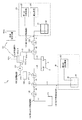
図5は本発明の液滴吐出装置の第2の実施形態を示す概略構成図である。なお、図1と同一部分には同一符号を付し、重複した構成、作用の説明は省略する。
本実施形態に係る液滴吐出装置1の特徴は、図1における洗浄液供給経路130(流路r4)の途中にバルブE(大気連通弁)131を配置した構成にある。バルブEからは大気連通路(流路r20)が延びている。バルブEは3方の経路(流路r4−1、r4−2、r20)に接続され、いずれか2方を連通させる機能を持つ。バルブEの一端が大気(空気流路r20)と連通しており、残り2方が洗浄液供給経路(流路r4−1、r4−2)に接続している(なお、バルブEを含めた同様の構成を図4の実施形態に適用してもよい)。
この構成において、ヘッド2内の洗浄液を排出する作業について説明する。
<< Second Embodiment >>
FIG. 5 is a schematic configuration diagram showing a second embodiment of the droplet discharge device of the present invention. In addition, the same code | symbol is attached | subjected to FIG. 1 and an identical part, and description of the overlapping structure and effect | action is abbreviate | omitted.
A feature of the
In this configuration, an operation for discharging the cleaning liquid in the
第1の実施形態中において説明したヘッド2の洗浄作業を実施した後では、洗浄液タンク41〜バルブE〜バルブC〜バルブA〜第1の供給口5の経路、及び、ヘッド内、第2のインク供給経路110に洗浄液42が残っている。なお、循環経路120は他の経路と連通しない状態としておくことは上述の通りである。
洗浄液を排出する作業においては、まずバルブEを大気とバルブC側の経路が通じるようにセットする。つまり、バルブEを操作して流路r20と流路r4−2とを連通させる。
更に、バルブA、及びバルブCを操作して、バルブEから第1の供給口5までの流路r4−2、r2、r3が通じるようにセットする。バルブBを操作して、バルブDから第2の供給口6まで(流路r6、r5)が通じるようにセットする。そしてバルブDを開くことにより、大気側の流路r7を流路r6と連通させる。
After performing the cleaning operation of the
In the operation of discharging the cleaning liquid, first, the valve E is set so that the atmosphere and the path on the valve C side communicate with each other. That is, by operating the valve E, the flow path r20 and the flow path r4-2 are communicated.
Further, the valves A and C are operated so that the flow paths r4-2, r2, and r3 from the valve E to the first supply port 5 are communicated. The valve B is operated and set so that the passage from the valve D to the second supply port 6 (the flow paths r6 and r5) is communicated. Then, by opening the valve D, the flow path r7 on the atmosphere side is communicated with the flow path r6.
次に、ヘッドを駆動し、ノズルから洗浄液を排出する。
これにより、ヘッド内の液室の洗浄液が消費され、バルブEに接続された空気流路r20からバルブC〜バルブA〜第1の供給口5〜ヘッドへ大気が流入する。また、第2のインク供給経路110を通じてバルブD〜バルブB〜第2の供給口6〜ヘッドへ大気が流入する。
これにより、第1のインク供給経路100、第2のインク供給経路110、ヘッド内の洗浄液を残らず排出し、空気流路r20から導入した空気に置き換えることができる。このように洗浄液とインクとが空気により分離されるので、洗浄液を排出する際に洗浄液とインクが混ざることが無くなり、洗浄液と混ざったインクをノズルから排出することによるインクの無駄な消費が無くなる。
Next, the head is driven and the cleaning liquid is discharged from the nozzle.
As a result, the cleaning liquid in the liquid chamber in the head is consumed, and the air flows from the air flow path r20 connected to the valve E to the valves C to A to the first supply port 5 to the head. In addition, air flows into the valve D to the valve B to the second supply port 6 to the head through the second ink supply path 110.
Thereby, the first
《第3の実施形態》
次に、図6は本発明の液滴吐出装置の第3の実施形態を示す概略構成図である。なお、図1、図5と同一部分には同一符号を付し、重複した構成、作用の説明は省略する。
本実施形態に係る液滴吐出装置1の特徴は、洗浄液供給経路130(流路r4)にバルブF(132)を配置し、バルブFから延びる流路r20の端部に第3の加圧装置(133)を配置した構成にある。バルブFは3方の経路(流路r4−1、r4−2、r20)に接続され、いずれか2方を連通させる機能を持つ。バルブFの一端が加圧装置(加圧手段)Cと連通しており、残り2方が洗浄液供給経路(流路r4−1、r4−2)に接続している。
第3の加圧装置133は、圧縮空気を送り出す機能を有する。
以上の構成において、ヘッド2内の洗浄液を排出する作業手順について説明する。
<< Third Embodiment >>
Next, FIG. 6 is a schematic configuration diagram showing a third embodiment of the droplet discharge device of the present invention. The same parts as those in FIGS. 1 and 5 are denoted by the same reference numerals, and the description of the overlapping configuration and operation is omitted.
A feature of the
The
In the above configuration, the operation procedure for discharging the cleaning liquid in the
第1の実施形態において説明したヘッド2の洗浄工程の後では、洗浄液タンク41〜バルブF〜バルブC〜バルブA〜第1の供給口5の経路、及び、ヘッド内、第2のインク供給経路110に洗浄液が残っている。
洗浄液の排出作業では、まず、バルブFを操作して第3の加圧装置133とバルブCとを結ぶ経路(流路r20と流路r4−2)とが通じるようにセットする(流路r4−1は遮断)。バルブA、及びバルブCを操作して、バルブFから第1の供給口5に至る流路r20、r4−2、r2、r3が連通するようにセットする。バルブBを操作して、バルブDから第2の供給口6へ至る流路r6、r5が通じるようにセットする。そしてバルブDを閉じる。
循環経路120は他の経路と連通しない状態としておくことは上述の通りである。
After the cleaning process of the
In the discharge operation of the cleaning liquid, first, the valve F is operated so that a path (flow path r20 and flow path r4-2) connecting the
As described above, the circulation path 120 is not in communication with other paths.
次に、第3の加圧装置を駆動し、バルブFへ圧縮空気を送り出す。
これにより、バルブF〜バルブC〜バルブA〜第1の供給口5の経路、及び、ヘッド内の洗浄液が圧縮空気によりノズルから押し出される。このとき、圧縮空気で押し出した洗浄液により、ノズルを再度洗浄することができる。
また、バルブF〜バルブC〜バルブA〜第1の供給口5の経路内、及びヘッド内の洗浄液がノズルから排出され、空気に置き換わる。
次に、バルブDを開くことにより、第3の加圧装置133からバルブFを経由してヘッドまで来ていた圧縮空気により、第2のインク供給経路110内部の洗浄液が廃液タンク50へ排出される。
また、洗浄液排出時にはノズルを加圧洗浄することができる。洗浄液を第2のインク供給経路の排出端側から外部に排出する際においてもノズルを洗浄できるため、洗浄液の消費量に対してノズルを洗浄する効率が向上する。
以上の操作により、第1のインク供給経路100、第2のインク供給経路110、ヘッド内の洗浄液を残らず排出することができる。
Next, the third pressurizer is driven to send compressed air to the valve F.
Thereby, the path | route of the valve | bulb F-the valve | bulb C-the valve | bulb A-the 1st supply port 5, and the washing | cleaning liquid in a head are extruded from a nozzle by compressed air. At this time, the nozzle can be cleaned again with the cleaning liquid extruded with compressed air.
Also, the cleaning liquid in the path from the valve F to the valve C to the valve A to the first supply port 5 and in the head is discharged from the nozzle and replaced with air.
Next, by opening the valve D, the cleaning liquid in the second ink supply path 110 is discharged to the
In addition, the nozzle can be pressure-washed when the cleaning liquid is discharged. Since the nozzle can be cleaned even when the cleaning liquid is discharged from the discharge end side of the second ink supply path to the outside, the efficiency of cleaning the nozzle with respect to the consumption of the cleaning liquid is improved.
By the above operation, all of the first
《本発明の液滴吐出装置を用いたプリンタ》
次に、本発明に係る液滴吐出装置は、画像形成装置(インクジェット記録装置)に適用可能である。
図7は、本発明の液滴吐出装置を用いたインクジェット記録装置の斜視説明図、図8は同記録装置の機構部の側面説明図である。
図7、図8に示すインクジェット記録装置は、記録装置本体201の内部に主走査方向に移動可能なキャリッジ、キャリッジに搭載した本発明を実施したインクジェットヘッドからなる記録ヘッド、記録ヘッドへインクを供給するインクカートリッジ等で構成される印字機構部202等を収納する。装置本体201の下方部には前方側から多数枚の用紙Pを積載可能な給紙カセット(或いは給紙トレイでもよい)204を抜き差し自在に装着することができる。また、用紙Pを手差しで給紙するための手差しトレイ205を開倒することができ、給紙カセット204或いは手差しトレイ205から給送される用紙Pを取り込み、印字機構部202によって所要の画像を記録した後、後面側に装着された排紙トレイ206に排紙する。
<< Printer using the droplet discharge device of the present invention >>
Next, the droplet discharge device according to the present invention can be applied to an image forming apparatus (inkjet recording apparatus).
FIG. 7 is a perspective explanatory view of an ink jet recording apparatus using the droplet discharge apparatus of the present invention, and FIG. 8 is a side explanatory view of a mechanism portion of the recording apparatus.
The ink jet recording apparatus shown in FIGS. 7 and 8 includes a carriage that can move in the main scanning direction inside the recording apparatus
印字機構部202は、図示しない左右の側板に横架したガイド部材である主ガイドロッド207と従ガイドロッド208とでキャリッジ209を主走査方向に摺動自在に保持する。このキャリッジ209にはイエロー(Y)、シアン(C)、マゼンタ(M)、ブラック(Bk)の各色のインク滴を吐出する本発明に係るインクジェットヘッドからなるヘッド210を複数のインク吐出口(ノズル孔)を主走査方向と交差する方向に配列し、インク滴吐出方向を下方に向けて装着している。またキャリッジ209にはヘッド210に各色のインクを供給するための各インクカートリッジ211を交換可能に装着している。
インクカートリッジ211は上方に大気と連通する大気口、下方にはインクジェットヘッドへインクを供給する供給口を、内部にはインクが充填された多孔質体を有しており、多孔質体の毛管力によりインクジェットヘッドへ供給されるインクをわずかな負圧に維持している。また、記録ヘッドとしてここでは各色のヘッド210を用いているが、各色のインク滴を吐出するノズル孔を有する1個のヘッドでもよい。
The
The
ここで、キャリッジ209は後方側(用紙搬送方向下流側)を主ガイドロッド207に摺動自在に嵌装し、前方側(用紙搬送方向上流側)を従ガイドロッド208に摺動自在に載置している。このキャリッジ209を主走査方向に移動走査するため、主走査モータ212で回転駆動される駆動プーリ213と従動プーリ214との間にタイミングベルト215を張装する。このタイミングベルト215をキャリッジ209に固定しており、主走査モータ212の正逆回転によりキャリッジ209が往復駆動される。
Here, the
一方、給紙カセット204にセットした用紙Pをヘッド210の下方側に搬送するために、給紙カセット204から用紙Pを分離給装する給紙ローラ216及びフリクションパッド217と、用紙Pを案内するガイド部材218と、給紙された用紙Pを反転させて搬送する搬送ローラ219と、この搬送ローラ219の周面に押し付けられる搬送コロ220及び搬送ローラ219からの用紙Pの送り出し角度を規定する先端コロ221とを設けている。搬送ローラ219は副走査モータ222によってギヤ列を介して回転駆動される。
そして、キャリッジ209の主走査方向の移動範囲に対応して搬送ローラ219から送り出された用紙Pを記録ヘッド210の下方側で案内する用紙ガイド部材である印写受け部材223を設けている。この印写受け部材223の用紙搬送方向下流側には、用紙Pを排紙方向へ送り出すために回転駆動される搬送コロ224、拍車225を設け、更に用紙Pを排紙トレイ206に送り出す排紙ローラ226及び拍車227と、排紙経路を形成するガイド部材228、229とを配設している。
記録時には、キャリッジ209を移動させながら画像信号に応じて記録ヘッド210を駆動することにより、停止している用紙Pにインクを吐出して1行分を記録し、用紙Pを所定量搬送後次の行の記録を行う。記録終了信号または、用紙Pの後端が記録領域に到達した信号を受けることにより、記録動作を終了させ用紙Pを排紙する。
On the other hand, in order to convey the paper P set in the
A printing receiving member 223 is provided as a paper guide member for guiding the paper P sent from the
At the time of recording, the
また、キャリッジ209の移動方向右端側の記録領域を外れた位置には、ヘッド210の吐出不良を回復するための回復装置230を配置している。回復装置230はキャップ手段と吸引手段とクリーニング手段を有している。キャリッジ209は印字待機中にはこの回復装置230側に移動されてキャッピング手段でヘッド210をキャッピングされ、吐出口部を湿潤状態に保つことによりインク乾燥による吐出不良を防止する。また、記録途中などに記録と関係しないインクを吐出することにより、全ての吐出口のインク粘度を一定にし、安定した吐出性能を維持する。
吐出不良が発生した場合等には、キャッピング手段でヘッド210の吐出口(ノズル孔)を密封し、チューブを通して吸引手段で吐出口からインクとともに気泡等を吸い出し、吐出口面に付着したインクやゴミ等はクリーニング手段により除去され吐出不良が回復される。また、吸引されたインクは、本体下部に設置された廃インク溜(不図示)に排出され、廃インク溜内部のインク吸収体に吸収保持される。
なお、本発明の液滴吐出装置は、インク以外の液体を吐出する他の画像形成装置一般に適用することができる。例えば、半導体プロセスで基板上に形成される液体レジストや、パターン材料等を液滴として吐出する装置(画像形成装置)にも適用することができる。
Further, a
When ejection failure occurs, etc., the ejection port (nozzle hole) of the
The droplet discharge device of the present invention can be applied to other image forming apparatuses that discharge liquids other than ink. For example, the present invention can be applied to an apparatus (image forming apparatus) that ejects liquid resist formed on a substrate in a semiconductor process, a pattern material, or the like as droplets.
《本発明の構成、作用、効果のまとめ》
第1の本発明に係る液滴吐出装置は、液滴を吐出するノズル3を有するヘッド2(液滴吐出部)と、液滴吐出部に液体を供給するための第1のインク供給経路100(第1の経路)、及び第2のインク供給経路110(第2の経路)と、第1のインク供給経路を介して液滴吐出部にインク22(第1の液体)を供給する第1の液体供給部20と、第1のインク供給経路に対してバルブA(第1の切り替え弁101)を介してつながると共に、第2のインク供給経路に対してバルブB(第2の切り替え弁111)を介してつながり、且つ液滴吐出部を迂回する循環経路120(第3の経路)と、を有する。更に、循環経路上に配置された液体循環手段122と、第1のインク供給経路、若しくは第2のインク供給経路とバルブC(第3の切り替え弁102)を介してつながる洗浄液供給経路130(第4の経路)と、洗浄液供給経路を介してヘッド2に洗浄液42(第2の液体)を供給する第2の液体供給部40と、第1のインク供給経路、若しくは第2のインク供給経路中の液体をヘッドへ流すために第1のインク供給経路、若しくは第2のインク供給経路上に設置されたバルブD(経路開閉手段112)と、を備えていることを特徴とする。
<< Summary of Configuration, Action, and Effect of the Present Invention >>
The droplet discharge device according to the first aspect of the present invention includes a head 2 (droplet discharge portion) having a
これによれば、ヘッド、及びその周囲の流路中のインクを循環するため、循環経路内にフィルタ等の異物除去手段を配置すれば循環中にインク中に発生した沈殿物によるノズルの目詰まりを防止できる。また、洗浄液でヘッドを洗浄できるため、ノズル部に固着したインクの固体成分を取り除き、ノズルの目詰まりを解消できる。
つまり、インク等の液体中の気泡、及び固体成分の沈殿によるノズルの目詰まりを防止する機構と、液体の乾燥によるノズル目詰まりを解消する機構と、を兼ね備えた液滴吐出装置を提供することができる。
According to this, in order to circulate the ink in the head and the flow path around it, if a foreign matter removing means such as a filter is arranged in the circulation path, the clogging of the nozzle due to the precipitate generated in the ink during the circulation. Can be prevented. In addition, since the head can be cleaned with the cleaning liquid, the clogging of the nozzle can be eliminated by removing the solid component of the ink fixed to the nozzle portion.
That is, to provide a droplet discharge device that has a mechanism for preventing clogging of nozzles due to bubbles in liquid such as ink and precipitation of solid components, and a mechanism for eliminating nozzle clogging due to drying of liquids. Can do.
第2の本発明に係る液滴吐出装置では、第3のインク供給経路上に脱気装置121a(脱気手段)を配置したことを特徴とする。
これによれば、ヘッド、及びその周囲の流路中のインクを脱気するため、気泡によるノズルの目詰まりを防止できる。
The liquid droplet ejection apparatus according to the second aspect of the present invention is characterized in that a
According to this, since the ink in the head and the flow path around the head is degassed, clogging of the nozzle due to bubbles can be prevented.
第3の本発明に係る液滴吐出装置では、第2の液体供給部40が液体を空圧で押し出す加圧装置43(加圧手段)を備えている。
洗浄液タンクからヘッドへ洗浄液を空圧で押し出すため、ポンプで洗浄液を押し出す場合と比べて洗浄液を強く押し出すことができて、ノズルを洗浄する能力を高めることができる。
In the droplet discharge device according to the third aspect of the present invention, the second
Since the cleaning liquid is pushed out from the cleaning liquid tank to the head by air pressure, the cleaning liquid can be pushed out more strongly than when the cleaning liquid is pushed out by a pump, and the ability to clean the nozzle can be enhanced.
第4の本発明に係る液滴吐出装置では、第1の液体供給部20が減圧装置24(減圧手段)を備えていることを特徴とする。
ヘッド部のインクを減圧して適正な圧力にするため、ノズルからインクが漏れ出すことを防ぐことができる。
In the droplet discharge device according to the fourth aspect of the present invention, the first
Since the ink in the head portion is reduced to an appropriate pressure, it is possible to prevent the ink from leaking from the nozzle.
第5の本発明に係る液滴吐出装置では、第1の液体供給部20と第2のインク供給経路110との間に圧力差を発生させてヘッド2から第1の液体供給部へインク(第1の液体)を回収する第1の液体回収機構を備えていること特徴とする。
ヘッドを洗浄する前にヘッドやその周囲の流路中のインクをインクタンクに回収できる。このため、ヘッドに洗浄液を流す際に、洗浄液と一緒にインクを無駄に排出することが無くなる。それにより、インクの消費量を減らすことができる。
In the liquid droplet ejection apparatus according to the fifth aspect of the present invention, a pressure difference is generated between the first
Before washing the head, the ink in the head and the flow path around it can be collected in the ink tank. For this reason, when the cleaning liquid is supplied to the head, the ink is not discharged wastefully together with the cleaning liquid. Thereby, ink consumption can be reduced.
第6の本発明に係る液滴吐出装置では、洗浄液供給経路130(第4の経路)上にバルブE(大気連通弁131)を備えていることを特徴とする。
これによれば、第1のインク供給経路100、第2のインク供給経路110、ヘッド内の洗浄液を残らず排出し、空気に置き換えることができる。洗浄液とインクとが空気により分離されるので、洗浄液を排出する際に洗浄液とインクが混ざることが無くなり、洗浄液と混ざったインクをノズルから排出することによるインクの無駄な消費が無くなる。
The liquid droplet ejection apparatus according to the sixth aspect of the present invention is characterized in that a valve E (atmospheric communication valve 131) is provided on the cleaning liquid supply path 130 (fourth path).
According to this, the first
第7の本発明に係る液滴吐出装置では、洗浄液供給経路130(第4の経路)にバルブF(132)を介してつながる加圧装置133(加圧手段)を備えていることを特徴とする。
洗浄液供給経路にバルブFを介して加圧装置133を配置することにより、バルブF〜バルブC〜バルブA〜第1の供給口5の経路、及び、ヘッド内の洗浄液がノズルから押し出され、ノズルを加圧洗浄することができる。また、上記経路内、及びヘッド内の洗浄液がノズルから排出され、空気に置き換わる。加圧装置133からバルブFを経由してヘッドまで来ていた圧縮空気により、第2のインク供給経路110内部の洗浄液が廃液タンク50へ排出される。これにより、第1のインク供給経路100、第2のインク供給経路110、ヘッド内の洗浄液を残らず排出することができる。
洗浄液を第2のインク供給経路の排出端側から外部に排出する際においてもノズルを洗浄できるため、洗浄液の消費量に対してノズルを洗浄する効率が向上する。
The droplet discharge device according to the seventh aspect of the present invention is characterized by including a pressurizing device 133 (pressurizing means) connected to the cleaning liquid supply path 130 (fourth path) via a valve F (132). To do.
By disposing the
Since the nozzle can be cleaned even when the cleaning liquid is discharged from the discharge end side of the second ink supply path to the outside, the efficiency of cleaning the nozzle with respect to the consumption of the cleaning liquid is improved.
第8の本発明に係る液滴吐出装置では、循環経路120(第3の経路)上に、液体中から微粒子を取り除くフィルタ123を配置したことを特徴とする。
ヘッド、及びその周囲の流路中のインクからフィルタがゴミ等の異物を除去するため、インク中のゴミ等によるノズルの目詰まりを防止できる。
The droplet discharge device according to the eighth aspect of the present invention is characterized in that a
Since the filter removes foreign matters such as dust from the ink in the head and the flow path around the head, it is possible to prevent clogging of the nozzles due to dust and the like in the ink.
第9の本発明に係る液滴吐出装置では、脱気装置121aが、液体を通さず気体を通す部材を介して液体室と気体室に分かれており、気体室に負圧を導入することで液体室中の液体を脱気することを特徴とする。
真空発生装置を用いて脱気しているため、液体容器内でインクを攪拌する脱気方法と異なり、インクを循環させながら脱気することができる。
In the droplet discharge device according to the ninth aspect of the present invention, the
Since the deaeration is performed using the vacuum generator, the deaeration can be performed while circulating the ink, unlike the deaeration method in which the ink is stirred in the liquid container.
本発明に係る液滴吐出装置を用いた脱気方法では、循環経路120(第3の経路)内に洗浄液(第2の液体)を循環させつつ脱気する脱気方法であって、第1の切り替え弁101と第3の経路120と第2の切り替え弁111と液滴吐出部2とを通る閉鎖された経路中に第2の液体42を充填させた状態で、液体循環手段122によって該第2の液体を循環させると共に、脱気手段121を用いて該第2の液体を脱気することを特徴とする。
インク等の液体中の気泡、及び固体成分の沈殿によるノズルの目詰まりを防止する機構と、液体の乾燥によるノズル目詰まりを解消する機構と、を兼ね備えた液滴吐出装置において、構成を複雑化することなく効果的に脱気を行うことが可能となる。
The degassing method using the droplet discharge device according to the present invention is a degassing method for degassing while circulating a cleaning liquid (second liquid) in a circulation path 120 (third path). In a state where the
Complicated configuration of a droplet discharge device that combines a mechanism for preventing clogging of nozzles due to precipitation of air bubbles and solid components such as ink and a mechanism for eliminating nozzle clogging due to liquid drying It becomes possible to perform deaeration effectively without doing.
本発明に係る液滴吐出装置を備えた脱気方法では、第3の経路中にフィルタを備え、液滴吐出部と第1の切り替え弁との間の第2の液体が、第1の切り替え弁を経て脱気手段へ一方向移動するように、閉鎖された経路内の第2の液体を循環させることを特徴とする。
ヘッドのノズル3からインクを吐出すると、流路r3内の未脱気のインクがバルブA(第1の切り替え弁)から第1の供給口5側へ供給されてしまう。未脱気のインク中に気泡が発生していた場合には、ヘッド内のノズルに気泡が付着するおそれがある。そこで、バルブAを経て脱気手段へ一方向移動するように循環させることにより、上記不具合を解消できる。
In the deaeration method including the droplet discharge device according to the present invention, the second liquid between the droplet discharge unit and the first switching valve is provided with the filter in the third path, and the first switching is performed. The second liquid in the closed path is circulated so as to move in one direction through the valve to the deaeration means.
When ink is ejected from the
本発明に係る液滴吐出装置において、液滴吐出部内の液室を洗浄した後に、ノズルを洗浄する洗浄方法にあっては、液滴吐出部の内部から第2の液体を回収する回収工程と、第4の経路と液滴吐出部内とを連通させる工程と、経路開閉手段を開放して、第2の経路を介して液滴吐出部内を大気と連通させる工程と、第2の液体供給部により第2の液体を送出して第1の経路、液滴吐出部内、及び第2の経路を洗浄する洗浄工程と、経路開閉手段を閉鎖してから第2の液体供給部からの第2の液体の送出を行うことにより、第2の液体をノズルから排出するノズル洗浄工程と、第2の液体供給部からの第2の液体の送出を停止する工程と、を備えたことを特徴とする。
この洗浄方法によれば、第2の供給口6付近で洗浄液とインクが混ざり合い、結果的に、その混合液を用いてノズルを洗浄することになる、という洗浄不良を防止することができる。
本発明に係る画像形成装置は、上記液滴吐出装置を備えたことを特徴とする。
In the droplet discharge device according to the present invention, in the cleaning method for cleaning the nozzle after cleaning the liquid chamber in the droplet discharge unit, a recovery step of recovering the second liquid from the inside of the droplet discharge unit; A step of communicating the fourth path with the inside of the droplet discharge unit, a step of opening the path opening / closing means to communicate the inside of the droplet discharge unit with the atmosphere via the second path, and a second liquid supply unit The second liquid is sent out to wash the first path, the droplet discharge section, and the second path, and the second opening from the second liquid supply section after closing the path opening / closing means. A nozzle cleaning step of discharging the second liquid from the nozzle by delivering the liquid and a step of stopping the delivery of the second liquid from the second liquid supply unit are provided. .
According to this cleaning method, it is possible to prevent a cleaning failure in which the cleaning liquid and the ink are mixed in the vicinity of the second supply port 6 and, as a result, the nozzle is cleaned using the mixed liquid.
An image forming apparatus according to the present invention includes the above-described droplet discharge device.
1…液滴吐出装置、2…ヘッド(液滴吐出部)、3…ノズル、5…供給口、6…供給口、20…第1の液体供給部、21…インクタンク、22…インク(第1の液体)、23…加圧装置(加圧手段)、24…減圧装置(減圧手段)、40…第2の液体供給部、41…洗浄液タンク、42…洗浄液(第2の液体)、43…加圧装置(加圧手段)、50…廃液タンク、100…第1のインク供給経路(第1の経路)、101…第1の切り替え弁、102…第3の切り替え弁、110…第2のインク供給経路(第2の経路)、111…第2の切り替え弁、112…経路開閉手段、120…循環経路、121…脱気手段、121a…脱気装置、121a−1…液体室、121a−2…気体室、121a−3…部材、121b…真空発生装置、121c…チューブ、122…ポンプ、122…液体循環手段、130…洗浄液供給経路、131…大気連通弁、133…加圧装置(加圧手段)、201…記録装置本体、202…印字機構部、204…給紙カセット、205…トレイ、206…排紙トレイ、207…主ガイドロッド、208…従ガイドロッド、209…キャリッジ、210…記録ヘッド、211…インクカートリッジ、212…主走査モータ、214…従動プーリ、215…タイミングベルト、216…給紙ローラ、217…フリクションパッド、218…ガイド部材、219…搬送ローラ、220…搬送コロ、221…先端コロ、222…副走査モータ、223…フィルタ、224…減圧装置、224…搬送コロ、225…拍車、226…排紙ローラ、227…拍車、228…ガイド部材、213…駆動プーリ、230…回復装置
DESCRIPTION OF
Claims (13)
前記液滴吐出部に液体を供給するための第1の経路、及び第2の経路と、
前記第1の経路を介して前記液滴吐出部に第1の液体を供給する第1の液体供給部と、
前記第1の経路に対して第1の切り替え弁を介してつながると共に、前記第2の経路に対して第2の切り替え弁を介してつながり、且つ前記液滴吐出部を迂回する第3の経路と、
前記第3の経路上に配置された液体循環手段と、
前記第1の経路、若しくは前記第2の経路と、第3の切り替え弁を介してつながる第4の経路と、
前記第4の経路を介して前記液滴吐出部に第2の液体を供給する第2の液体供給部と、
前記第1の経路、若しくは前記第2の経路中の液体を前記液滴吐出部へ流すために前記第1の経路、若しくは前記第2の経路上に設置された経路開閉手段と、
を備えていることを特徴とする液滴吐出装置。 A droplet discharge section having a nozzle for discharging droplets;
A first path and a second path for supplying liquid to the droplet discharge section;
A first liquid supply section for supplying a first liquid to the droplet discharge section via the first path;
A third path connected to the first path via a first switching valve, connected to the second path via a second switching valve, and bypassing the droplet discharge section When,
Liquid circulation means disposed on the third path;
A fourth path connected to the first path or the second path via a third switching valve;
A second liquid supply section for supplying a second liquid to the droplet discharge section via the fourth path;
A path opening / closing means installed on the first path or the second path to flow the liquid in the first path or the second path to the droplet discharge section;
A droplet discharge device comprising:
前記第3の経路上に脱気手段を配置したことを特徴とする液滴吐出装置。 The droplet discharge device according to claim 1,
A liquid droplet ejection apparatus, wherein a deaeration unit is disposed on the third path.
前記脱気手段が、液体を通さず気体を通す部材を介して液体室と気体室に分かれており、前記気体室に負圧を導入することで前記液体室中の液体を脱気することを特徴とする液滴吐出装置。 The droplet discharge device according to claim 2 ,
The deaeration means is divided into a liquid chamber and a gas chamber through a member that allows gas to pass therethrough, and degass the liquid in the liquid chamber by introducing a negative pressure into the gas chamber. A droplet discharge apparatus characterized by the above.
前記第2の液体供給部が液体を空圧で押し出す加圧手段を備えていることを特徴とする液滴吐出装置。 The liquid droplet ejection apparatus according to any one of claims 1 to 3 ,
The liquid droplet ejection apparatus, wherein the second liquid supply unit includes a pressurizing unit for extruding the liquid by air pressure.
前記第1の液体供給部が減圧手段を備えていることを特徴とする液滴吐出装置。 The droplet discharge device according to any one of claims 1 to 4 ,
The liquid droplet ejection apparatus, wherein the first liquid supply unit includes a decompression unit.
前記第1の液体供給部と前記第2の経路との間に圧力差を発生させて前記液滴吐出部から前記第1の液体供給部へ第1の液体を回収する第1の液体回収機構を備えていること特徴とする液滴吐出装置。 In the droplet discharge device according to any one of claims 1 to 5 ,
A first liquid recovery mechanism that generates a pressure difference between the first liquid supply unit and the second path to recover the first liquid from the droplet discharge unit to the first liquid supply unit. A droplet discharge device comprising:
前記第4の経路上に大気連通弁を備えていることを特徴とする液滴吐出装置。 In the droplet discharge device according to any one of claims 1 to 6 ,
A droplet discharge device comprising an atmosphere communication valve on the fourth path.
前記第4の経路に第4の切り替え弁を介してつながる加圧手段を備えていることを特徴とする液滴吐出装置。 In the droplet discharge device according to any one of claims 1 to 7 ,
A droplet discharge apparatus comprising a pressurizing unit connected to the fourth path via a fourth switching valve.
前記第3の経路上に、前記液体中から微粒子を取り除くフィルタを配置したことを特徴とする液滴吐出装置。 The droplet discharge device according to any one of claims 1 to 8 ,
A droplet discharge device, wherein a filter for removing fine particles from the liquid is disposed on the third path.
前記第1の切り替え弁と前記第3の経路と前記第2の切り替え弁と前記液滴吐出部とを通る閉鎖された経路中に前記第1の液体を充填させた状態で、前記液体循環手段によって該第1の液体を循環させると共に、請求項2に記載の脱気手段を用いて該第1の液体を脱気することを特徴とする脱気方法。 The liquid droplet ejection apparatus according to any one of claims 1 to 9, wherein the degassing method is for degassing while circulating the first liquid in the third path,
In a state where the first liquid is filled in a closed path passing through the first switching valve, the third path, the second switching valve, and the droplet discharge section, the liquid circulation means The degassing method is characterized in that the first liquid is circulated by the degassing and the degassing means according to claim 2 is used to degas the first liquid.
前記液滴吐出部と前記第1の切り替え弁との間の前記第1の液体が、前記第1の切り替え弁を経て前記脱気手段へ一方向移動するように、前記閉鎖された経路内の前記第1の液体を循環させることを特徴とする脱気方法。 The deaeration method according to claim 10, comprising the filter according to claim 9 in the third path.
The first liquid between the droplet discharge unit and the first switching valve moves in one direction to the deaeration means via the first switching valve, and is in the closed path. A degassing method comprising circulating the first liquid.
前記液滴吐出部の内部から前記第1の液体を回収する回収工程と、
前記第4の経路と前記液滴吐出部内とを連通させる工程と、
前記経路開閉手段を開放して、前記第2の経路を介して前記液滴吐出部内を大気と連通させる工程と、
前記第2の液体供給部により前記第2の液体を送出して第1の経路,前記液滴吐出部内、及び前記第2の経路を洗浄する洗浄工程と、
前記経路開閉手段を閉鎖してから前記第2の液体供給部からの前記第2の液体の送出を行うことにより、前記第2の液体を前記ノズルから排出するノズル洗浄工程と、
前記第2の液体供給部からの第2の液体の送出を停止する工程と、
を備えたことを特徴とするノズルの洗浄方法。 The droplet discharge device according to any one of claims 1 to 9, wherein the nozzle is cleaned after cleaning the liquid chamber in the droplet discharge unit.
A recovery step of recovering the first liquid from the inside of the droplet discharge section;
Communicating the fourth path with the inside of the droplet discharge section;
Opening the path opening / closing means and communicating the inside of the droplet discharge unit with the atmosphere via the second path;
A washing step of sending the second liquid from the second liquid supply unit to wash the first path, the droplet discharge unit, and the second path;
A nozzle cleaning step of discharging the second liquid from the nozzle by delivering the second liquid from the second liquid supply section after closing the path opening / closing means;
Stopping the delivery of the second liquid from the second liquid supply unit;
A method for cleaning a nozzle, comprising:
Priority Applications (1)
| Application Number | Priority Date | Filing Date | Title |
|---|---|---|---|
| JP2014010425A JP6318641B2 (en) | 2014-01-23 | 2014-01-23 | Droplet discharge device, degassing method, nozzle cleaning method, and image forming apparatus |
Applications Claiming Priority (1)
| Application Number | Priority Date | Filing Date | Title |
|---|---|---|---|
| JP2014010425A JP6318641B2 (en) | 2014-01-23 | 2014-01-23 | Droplet discharge device, degassing method, nozzle cleaning method, and image forming apparatus |
Publications (2)
| Publication Number | Publication Date |
|---|---|
| JP2015136887A JP2015136887A (en) | 2015-07-30 |
| JP6318641B2 true JP6318641B2 (en) | 2018-05-09 |
Family
ID=53768220
Family Applications (1)
| Application Number | Title | Priority Date | Filing Date |
|---|---|---|---|
| JP2014010425A Expired - Fee Related JP6318641B2 (en) | 2014-01-23 | 2014-01-23 | Droplet discharge device, degassing method, nozzle cleaning method, and image forming apparatus |
Country Status (1)
| Country | Link |
|---|---|
| JP (1) | JP6318641B2 (en) |
Families Citing this family (4)
| Publication number | Priority date | Publication date | Assignee | Title |
|---|---|---|---|---|
| EP3211048B1 (en) * | 2016-02-25 | 2020-07-08 | Ricoh Company, Ltd. | Surface treatment liquid composition, ink set, recording method, and recording device |
| JP6941269B2 (en) * | 2016-10-17 | 2021-09-29 | 株式会社リコー | Ink ejection device and ink ejection method |
| JP7098104B2 (en) * | 2018-03-20 | 2022-07-11 | 株式会社リコー | Inkjet printing method and inkjet printing equipment |
| JP7380311B2 (en) | 2020-02-21 | 2023-11-15 | 株式会社リコー | liquid discharge device |
Family Cites Families (4)
| Publication number | Priority date | Publication date | Assignee | Title |
|---|---|---|---|---|
| JP4746305B2 (en) * | 2004-10-28 | 2011-08-10 | 株式会社アルバック | Head module |
| JP4710356B2 (en) * | 2005-03-08 | 2011-06-29 | 富士ゼロックス株式会社 | Droplet discharge device |
| JP2008023806A (en) * | 2006-07-20 | 2008-02-07 | Olympus Corp | Inkjet recording device |
| EP2305475A1 (en) * | 2008-06-24 | 2011-04-06 | Mastermind Co., Ltd. | Printing device |
-
2014
- 2014-01-23 JP JP2014010425A patent/JP6318641B2/en not_active Expired - Fee Related
Also Published As
| Publication number | Publication date |
|---|---|
| JP2015136887A (en) | 2015-07-30 |
Similar Documents
| Publication | Publication Date | Title |
|---|---|---|
| US8480214B2 (en) | Liquid jetting head unit and image forming apparatus | |
| JP6256692B2 (en) | Liquid ejecting apparatus and control method thereof | |
| US20120050421A1 (en) | Inkjet printing device and method for replacing a print head | |
| US8764176B2 (en) | Liquid ejecting apparatus | |
| JP5975204B2 (en) | Liquid ejector | |
| JP6318641B2 (en) | Droplet discharge device, degassing method, nozzle cleaning method, and image forming apparatus | |
| JP2011161714A (en) | Liquid ejecting apparatus, and nozzle recovery method in liquid ejecting apparatus | |
| JP2010264678A (en) | Liquid ejector | |
| JP2010208187A (en) | Liquid jetting apparatus | |
| JP2010208143A (en) | Liquid delivering apparatus and method for controlling liquid delivering apparatus | |
| JP5995184B2 (en) | Image forming apparatus | |
| JP2006068904A (en) | Liquid drop ejector | |
| JP6103199B2 (en) | Liquid ejector | |
| JP2004009475A (en) | Ink jet recording device and ink supply device used therein | |
| JP2018094868A (en) | Inkjet printer and method for cleaning ink head in inkjet printer | |
| JP5371699B2 (en) | Recording device | |
| JP5953800B2 (en) | Image forming apparatus | |
| JP2005125653A (en) | Inkjet head, inkjet recorder, and device and method of cleaning inkjet head | |
| JP2009101668A (en) | Ink supply control method | |
| JP2004050472A (en) | Inkjet recorder | |
| JP2007015374A (en) | Inkjet printer and method for removing bubble in inkjet printer | |
| JP7226012B2 (en) | Droplet ejection device | |
| JP2005131791A (en) | Ink jet head and ink jet recorder | |
| JP2009208368A (en) | Flow path forming member, liquid injection head, and liquid injection apparatus | |
| JP2012240270A (en) | Liquid ejection device, and inkjet recorder |
Legal Events
| Date | Code | Title | Description |
|---|---|---|---|
| A621 | Written request for application examination |
Free format text: JAPANESE INTERMEDIATE CODE: A621 Effective date: 20170110 |
|
| A131 | Notification of reasons for refusal |
Free format text: JAPANESE INTERMEDIATE CODE: A131 Effective date: 20170926 |
|
| A977 | Report on retrieval |
Free format text: JAPANESE INTERMEDIATE CODE: A971007 Effective date: 20170927 |
|
| A521 | Request for written amendment filed |
Free format text: JAPANESE INTERMEDIATE CODE: A523 Effective date: 20171127 |
|
| TRDD | Decision of grant or rejection written | ||
| A01 | Written decision to grant a patent or to grant a registration (utility model) |
Free format text: JAPANESE INTERMEDIATE CODE: A01 Effective date: 20180306 |
|
| A61 | First payment of annual fees (during grant procedure) |
Free format text: JAPANESE INTERMEDIATE CODE: A61 Effective date: 20180319 |
|
| R151 | Written notification of patent or utility model registration |
Ref document number: 6318641 Country of ref document: JP Free format text: JAPANESE INTERMEDIATE CODE: R151 |
|
| LAPS | Cancellation because of no payment of annual fees |