JP2009208368A - Flow path forming member, liquid injection head, and liquid injection apparatus - Google Patents
Flow path forming member, liquid injection head, and liquid injection apparatus Download PDFInfo
- Publication number
- JP2009208368A JP2009208368A JP2008054157A JP2008054157A JP2009208368A JP 2009208368 A JP2009208368 A JP 2009208368A JP 2008054157 A JP2008054157 A JP 2008054157A JP 2008054157 A JP2008054157 A JP 2008054157A JP 2009208368 A JP2009208368 A JP 2009208368A
- Authority
- JP
- Japan
- Prior art keywords
- flow path
- fluid
- forming member
- ink
- head
- Prior art date
- Legal status (The legal status is an assumption and is not a legal conclusion. Google has not performed a legal analysis and makes no representation as to the accuracy of the status listed.)
- Withdrawn
Links
Images


Abstract
Description
本発明は、流路形成部材及び液体噴射ヘッド及び液体噴射装置に関する。 The present invention relates to a flow path forming member, a liquid ejecting head, and a liquid ejecting apparatus.
液体噴射ヘッドの代表例としては、例えば、圧電素子の変位による圧力を利用してノズル開口からインク滴を吐出するインクジェット式記録ヘッドが知られている。従来から知られているインクジェット式記録ヘッドは、インクが充填されたインクカートリッジ等の流体源からヘッド本体にインクが供給され、ヘッド本体から供給されたインクは圧電素子や発熱素子等の圧力発生手段を駆動させることによりノズルから吐出される。 As a typical example of a liquid ejecting head, for example, an ink jet recording head that ejects ink droplets from nozzle openings using pressure generated by displacement of a piezoelectric element is known. A conventionally known ink jet recording head is supplied with ink from a fluid source such as an ink cartridge filled with ink to the head body, and the ink supplied from the head body is pressure generating means such as a piezoelectric element or a heating element. Is discharged from the nozzle by driving.
例えば、インクカートリッジにインク供給針を挿入することでインク供給針の導入孔からインクカートリッジ内のインクをヘッド本体の圧力室側に導入している。また、記録装置本体側に配置したインクカートリッジとヘッド本体側のインク供給針とをインクチューブで連結し、ポンプ等の圧送手段によりインクカートリッジ内のインクをヘッド本体の圧力室側に導入する技術も知られている。 For example, by inserting the ink supply needle into the ink cartridge, the ink in the ink cartridge is introduced from the introduction hole of the ink supply needle to the pressure chamber side of the head body. Also, there is a technique in which an ink cartridge arranged on the recording apparatus main body side and an ink supply needle on the head main body side are connected by an ink tube, and ink in the ink cartridge is introduced to the pressure chamber side of the head main body by a pumping means such as a pump. Are known.
このインクジェット式記録ヘッドでは、インクカートリッジのインク内に存在する気泡、あるいはインクカートリッジを着脱する際にインク内に混入した気泡がヘッド本体に供給されてしまうと、この気泡によるドット抜け等の吐出不良が発生するという問題がある。このような問題を解決するために、インク供給針とヘッド本体との間のインク流路にフィルタを装着したものが提案されている(例えば、特許文献1参照)。インク供給針内で気泡を溜めることでヘッド本体に気泡が流れ込むことを防止することができる。 In this ink jet recording head, if bubbles that are present in the ink of the ink cartridge or bubbles that are mixed in the ink when the ink cartridge is attached or detached are supplied to the head body, defective ejection such as missing dots due to the bubbles. There is a problem that occurs. In order to solve such a problem, there has been proposed one in which a filter is attached to the ink flow path between the ink supply needle and the head body (see, for example, Patent Document 1). By collecting bubbles in the ink supply needle, it is possible to prevent the bubbles from flowing into the head body.
また近年の高速印刷の要望により、インクジェット式記録ヘッドの吐出流量は増加傾向にあり、それに伴うフィルタ部の圧力損失も増加するという問題がある。 In addition, due to the recent demand for high-speed printing, there is a problem that the discharge flow rate of the ink jet recording head tends to increase, and the pressure loss of the filter portion associated therewith increases.
そこで、複数平面にフィルタをレイアウトした技術が提案されている(例えば、特許文献2参照)。特許文献2に開示された技術では、フィルタの圧力損失を低減するためにフィルタ面積を大型化してもフィルタユニットの大型化を抑制することができる。
Therefore, a technique in which filters are laid out on a plurality of planes has been proposed (see, for example, Patent Document 2). With the technique disclosed in
しかしながら、上記従来技術では、フィルタは略水平面に配置されているため、フィルタ面積の増加によるインク供給針やフィルタユニットのサイズには限界があり、インクジェット式記録ヘッドを複数個並べて使用する,いわゆるマルチヘッド化した場合には装置の肥大化が避けられない状況であった. However, in the above prior art, since the filter is arranged in a substantially horizontal plane, there is a limit to the size of the ink supply needle and the filter unit due to the increase in the filter area. When heads were used, it was inevitable that the equipment would be enlarged.
本発明は上記状況に鑑みてなされたもので、流体源の流体をヘッド本体に供給するための流体流路で、気泡を制御することができる流路形成部材を提供することを目的とする。 The present invention has been made in view of the above situation, and an object of the present invention is to provide a flow path forming member capable of controlling bubbles in a fluid flow path for supplying a fluid of a fluid source to a head body.
また、本発明は上記状況に鑑みてなされたもので、流体源の流体をヘッド本体に供給するための流体流路で、気泡を制御することができ、かつマルチヘッド化した際の投影面積(フットスペース)を極小化することが可能な流路形成部材を備えた液体噴射ヘッド及び液体噴射装置を提供することを目的とする。 In addition, the present invention has been made in view of the above situation, and is a fluid flow path for supplying the fluid of the fluid source to the head main body, and can control the bubbles, and the projected area when the multi-head is formed ( An object is to provide a liquid ejecting head and a liquid ejecting apparatus including a flow path forming member capable of minimizing a foot space.
上記目的を達成するための本発明の流路形成部材は、流体源の流体をヘッド本体に供給するための流体流路が形成された流路形成部材において、前記流体流路は、前記流体源からの流体を水平方向に流通させる水平部、及び、前記水平部に連続して下方向に流通させる鉛直部を有する第一の流路と、前記第一の流路の前記水平部及び前記鉛直部の間で前記流体を流通させる第二の流路とを備え、前記流体流路の前記第一の流路及び前記第二の流路は、気泡の浮力及び前記流体源からの流体の流量に応じて気泡の流れを制御する形状とされることを特徴とする。
このため、流体流路の第一の流路及び第二の流路により気泡の流れを所望の状態に制御することができ、気泡を流体流路内に留めた状態で流体の流通を許容したり、気泡を下流側に流通させる等の任意の制御が可能になる。
In order to achieve the above object, a flow path forming member of the present invention is a flow path forming member in which a fluid flow path for supplying a fluid of a fluid source to a head body is formed. A first flow path having a horizontal section that circulates fluid from the horizontal direction and a vertical section that circulates downward in a continuous manner to the horizontal section, and the horizontal section and the vertical section of the first flow path A second flow path for allowing the fluid to circulate between the sections, and the first flow path and the second flow path of the fluid flow path are buoyancy of bubbles and a flow rate of the fluid from the fluid source. According to the method, the flow of the bubbles is controlled.
For this reason, the flow of bubbles can be controlled to a desired state by the first flow path and the second flow path of the fluid flow path, and the flow of the fluid is allowed with the bubbles kept in the fluid flow path. Arbitrary control such as circulating air bubbles downstream is possible.
また、本発明の流体形成部材は、上述した流路形成部材において、前記流体流路の出口部と前記ヘッド本体の流体入口との間には前記流体の流れ方向に対向する第一のフィルタが備えられていることを特徴とする。
このため、ヘッド吐出能力に応じてフィルタ面積を拡大してもヘッド投影面積であるフットスペースを極小化することが可能になる。更に、気泡を流体流路内で分離して流通させることで、気泡が抜け難い鉛直方向に面を有する第一のフィルタであっても、有効面積を十分に確保することが可能になる。
Further, the fluid forming member of the present invention is the above-described channel forming member, wherein a first filter facing the fluid flow direction is provided between the outlet of the fluid channel and the fluid inlet of the head body. It is provided.
For this reason, it is possible to minimize the foot space, which is the head projection area, even if the filter area is increased in accordance with the head ejection capacity. Furthermore, by separating and circulating the bubbles in the fluid flow path, it is possible to secure a sufficient effective area even with the first filter having a surface in the vertical direction in which the bubbles are difficult to escape.
また、本発明の流路形成部材は、上述した流路形成部材において、前記流体流路の前記第一の流路及び前記第二の流路は、前記ヘッド本体側の駆動により前記流体が流通する際には前記気泡を前記第一の流路に留め、例えば、気泡を除去するためのメンテナンス動作時による吸引圧力が印加された際には前記気泡を下流側に流通させる形状とされていることを特徴とする。 Further, the flow path forming member of the present invention is the above-described flow path forming member, wherein the fluid flows by driving the head body side through the first flow path and the second flow path of the fluid flow path. For example, the bubbles are retained in the first flow path, and, for example, when a suction pressure is applied during a maintenance operation for removing the bubbles, the bubbles are circulated downstream. It is characterized by that.
また、上述した流路形成部材において、前記流体源が接続される部位と前記流体流路の入口部との間には、第二のフィルタが備えられ、前記第二のフィルタの後流側には、前記ヘッド本体側の流路の圧力が相対的に低下した際に前記流体の流通を許容する弁体が備えられていることを特徴とする。 Further, in the above-described flow path forming member, a second filter is provided between a portion to which the fluid source is connected and an inlet portion of the fluid flow path, and on the downstream side of the second filter. Is provided with a valve body that allows the fluid to flow when the pressure in the flow path on the head main body side is relatively lowered.
これらにより、流路に平行なフィルタを備えて幅寸法を狭めた流路形成部材において、気泡の影響を抑制することが可能になる。 Accordingly, it is possible to suppress the influence of bubbles in the flow path forming member that includes a filter parallel to the flow path and has a narrow width.
上記目的を達成するための本発明の液体噴射ヘッドは、上述した流路形成部材と、前記流体形成部材の前記流体流路の出口側に接続されノズル開口を有するヘッド本体とを備えたことを特徴とする。 In order to achieve the above object, a liquid jet head according to the present invention includes the above-described flow path forming member and a head body connected to an outlet side of the fluid flow path of the fluid forming member and having a nozzle opening. Features.
また、上述した液体噴射ヘッドにおいて、前記流路形成部材はヘッド本体に固定され、前記ヘッド本体のノズル開口に連通するリザーバ室に前記流体流路の出口側が連通していることを特徴とする。 In the above-described liquid ejecting head, the flow path forming member is fixed to the head main body, and an outlet side of the fluid flow path communicates with a reservoir chamber that communicates with a nozzle opening of the head main body.
上記目的を達成するための本発明の液体噴射装置は、上述した液体噴射ヘッドと、前記流路形成部材の前記流体流路の入口側に接続される流体源とを備えたことを特徴とする。 In order to achieve the above object, a liquid ejecting apparatus of the present invention includes the above-described liquid ejecting head and a fluid source connected to an inlet side of the fluid flow path of the flow path forming member. .
これらにより、流体源の流体をヘッド本体に供給するための流体流路で、気泡を制御することができる流路形成部材を備えた液体噴射ヘッド及び液体噴射装置とすることができる。 Accordingly, the liquid ejecting head and the liquid ejecting apparatus including the flow path forming member that can control the bubbles in the fluid flow path for supplying the fluid of the fluid source to the head body can be provided.
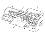
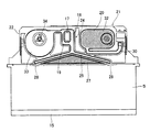
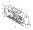
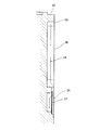
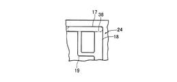
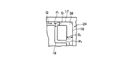
図1には本発明の一実施形態例に係るインク噴射ヘッドを備えたインクジェット式記録装置の概略構成、図2にはインク噴射ヘッドの主要部の断面側面、図3には流路形成部材の外観、図4には図2中の平面視、図5には図2中の要部詳細、図6には図5中のVI−VI線矢視を示してある。また、図7、図8には気泡の制御状況を表す流体流路の概念を示してある。 1 is a schematic configuration of an ink jet recording apparatus provided with an ink jet head according to an embodiment of the present invention, FIG. 2 is a cross-sectional side view of a main part of the ink jet head, and FIG. FIG. 4 shows a plan view in FIG. 2, FIG. 5 shows the details of the main part in FIG. 2, and FIG. 6 shows a VI-VI line arrow in FIG. 7 and 8 show the concept of the fluid flow path indicating the control state of the bubbles.
図1に基づいてインクジェット式記録装置を説明する。
図に示すように、液体噴射装置としてのインクジェット式記録装置(装置本体)1は、インクカートリッジ2が搭載されるキャリッジ3やキャリッジ3に取り付けられた記録ヘッド4等が一体化された液体噴射ヘッドとしてのヘッドユニット5を有している。キャリッジ3はタイミングベルト6を介してステッピングモータ7に接続され、ガイドバー8に案内されて記録紙9の紙幅方向(主走査方向)に往復移動するようになっている。キャリッジ3は上部に開放する箱型をなし、記録紙9と対面する面(下面)に記録ヘッド4のノズル面が露呈するよう取り付けられると共に、インクカートリッジ2が収容されるようになっている。
An ink jet recording apparatus will be described with reference to FIG.
As shown in the figure, an ink jet recording apparatus (apparatus main body) 1 as a liquid ejecting apparatus is a liquid ejecting head in which a carriage 3 on which an
記録ヘッド4にはインクカートリッジ2からインクが供給され、キャリッジ3を移動させながら記録紙9の上面にインク滴を吐出させて記録紙9に画像や文字をドットマトリックスにより印刷するようになっている。図1中の符号で、10は印刷休止中に記録ヘッド4のノズル開口を封止することによりノズルの乾燥を防止すると共に記録ヘッド4のノズル面に負圧を作用させてクリーニング動作をするキャップであり、11は記録ヘッド4のノズル面をワイピングするワイパーブレードであり、12はクリーニング動作で吸引した廃インクを貯留する廃インク貯留部であり、13は装置本体1の動作を制御する制御装置である。
Ink is supplied from the
図示のヘッドユニット5には、インクカートリッジ2からインクを記録ヘッド4に供給するための流路が形成された流路形成部材が備えられている。尚、図1の例では、キャリッジ3に流体源としてのインクカートリッジ2が収容される例を挙げて説明したが、インクカートリッジがキャリッジ3とは別の場所に収容され、供給管を介してインクが記録ヘッド4の流路形成部材に圧送される構成のインクジェット式記録装置であっても本発明を適用することが可能である。
The illustrated
図2に基づいてヘッドユニット5を説明する。
図に示すように、ヘッドユニット5は、例えば、圧電素子等の圧力発生手段が備えられ、圧電素子の変位による圧力を利用してノズルプレート15のノズル開口からインク滴を吐出するようになっている。ヘッドユニット5にはリザーバ室が設けられると共に、ヘッドユニット5の上部には流路形成部材21が接続されている。ヘッドユニット5のヘッド流路には流路形成部材21から流体としてのインクが供給され、ヘッド流路からリザーバ室にインクが送られる。そして、流路形成部材21にはインクカートリッジ2からインクが供給されるようになっている。例えば、供給管やインク供給針を介してインクカートリッジ2から流路形成部材21にインクが供給される。
The
As shown in the figure, the
図2〜図6に基づいて流路形成部材21を具体的に説明する。
流路形成部材21は矩形状の盤面を有する直方体ブロック形状とされ、樹脂製の本体22の両方の盤面にフィルム20が溶着されることで第一の流路24(流体流路)がそれぞれ形成される構成となっている。第一の流路24の下部には出口流路25が連続して設けられ、出口流路25は下流側(下側)に向けて幅広状態に形成されている。出口流路25の内側には第一のフィルタ27が備えられ、第一のフィルタ27は、幅広状態の出口流路25に略対応する面積で盤面の広い部分に配され、大面積が確保されている。第一のフィルタ27では、主に、後述する弁体34(機械的構成部材)を流通したインクに含まれる異物がトラップされる。
The flow
The flow
第一のフィルタ27はインクの流れ方向に対向する面(盤面と平行な面)を有し、第一の流路24を流通したインクは盤面の外側から第一のフィルタ27を通って本体22の内側の下部に送られ、2つの排出孔28からヘッドユニット5(図2参照)に送られる。第一の流路24を流通して出口流路25に送られたインクは、狭い流路から広い流路に広がって第一のフィルタ27を通り(図6参照)、端部の排出孔28からヘッドユニット5(図2参照)の一つのリザーバ室に送られる。つまり、それぞれの第一の流路24及び出口流路25に対して一つのリザーバ室につながる2つの排出孔28が設けられ、一つの流路形成部材21には4つの排出孔28が設けられている(図4参照)。
The
主に図5に示すように、第一の流路24は、インクを水平方向に流通させる水平部17と、水平部に連続して下方向に延びる鉛直部18とを有している。鉛直部18の下端が出口流路25につながり、水平部17と鉛直部18との間には第二の流路19が接続されている。水平部17及び鉛直部18で逆L字状の流路が形成され、第二の流路19はL字状の流路とされ、水平部17及び鉛直部18の逆L字状の流路と、第二の流路19のL字状の流路とで長方形状の流路が形成されている。水平部17及び鉛直部18、第二の流路19は、気泡の浮力及びインクの流量(流通圧力)に応じて気泡の流れが制御される形状にされている(詳細は後述する)。
As shown mainly in FIG. 5, the
流路形成部材21の上部の端部にはインク導入孔31がそれぞれ設けられ、インク導入孔31にはインクカートリッジ2からインクがそれぞれ供給される。一方(図4中左側)のインク導入孔31に供給されたインクは、所定の流路30を経由して図2に示した第一の流路24の入口側に送られ、他方(図4中右側)のインク導入孔31に供給されたインクは、所定の流路30を経由して図2の紙面の裏側に設けられた第一の流路24の入口部に送られる。
Ink introduction holes 31 are respectively provided at upper ends of the flow
インク導入孔31につながる流路30は、図4中矢印Aで示すように、一方(図4中左側)のインク導入孔31に供給されたインクが、図4中上側に流通した後下側に向かい、第二のフィルタ32を流通して図2に示したインク室33に送られるように形成されている。また、流路30は、図4中矢印Bで示すように、他方(図4中右側)のインク導入孔31に供給されたインクが、図4中下側に流通した後、図2に示した第二のフィルタ32を流通して図4中上側に向かい、図2のインク室33に送られるように形成されている。第二のフィルタ32は盤面と平行な面を有し、第一のフィルタ27と平行な状態で配されている。
As shown by an arrow A in FIG. 4, the
インク導入孔31(第二のフィルタ32)とインク室33(第一の流路24の入口側)の間の流路30には弁体34がそれぞれ設けられ、ヘッドユニット5(図2参照)のリザーバ室の圧力が低下した際に、即ち、インクが吐出されて第一の流路24側の圧力が相対的に低下した際に弁体34はインクの流通を許容するように作動する。つまり、所定の圧力でインクがインク導入孔31から供給される状態にある場合に、ヘッドユニット5(図2参照)のリザーバ室にインクが貯留されている際には弁体34は閉状態にされ、インクの吐出により後流側の圧力が低下すると、負圧力により弁体34が開状態にされてインクが供給される。
A
図7、図8に基づいて第一の流路24における気泡の制御状況を概念的に説明する。
第一の流路24に気泡38が混入した状態でインクの流れがない場合、図7に示すように、気泡38は浮力により第一の流路24の水平部17に留まり、第二の流路19の入口が塞がれた状態にされる。第一の流路24に気泡38が混入した状態で流量Qのインクが供給された場合、図8に示すように、気泡38の浮力と出口流路25側からの印字の時の吸引力(相対的な出口流路25側の低圧状態)により気泡38が制御され、第二の流路19の入口を開通した状態にして気泡38が水平部17及び鉛直部18にわたって停滞する。つまり、印字によりインクが吐出してヘッド本体側の流路が相対的に低圧力になってインクが流通する際には、第二の流路19の入口が開通してインクが第二の流路を通って出口流路25側に送られるように気泡38が留められる。また、クリーニング時で出口流路25側から大きな吸引力が印加された場合、気泡38は出口流路25側に吸引されて排出される(下流側に流通する)。
Based on FIGS. 7 and 8, the control state of bubbles in the
When there is no ink flow in the state where the air bubbles 38 are mixed in the
気泡38が制御される原理を説明する。
第二の流路19の入口の圧力をP1、第二の流路19の出口の圧力をP2とすると、出口流路25側への力ΔPは、
ΔP=P2−P1とすることができる。
第二の流路19の抵抗係数(インクの粘度、流路の断面積により決まる係数)をkとすると、ΔP=k・Qとなり、ΔP、即ち、P1、P2は、k(第二の流路19の設計寸法)とQ(流量)で決定される。
The principle by which the
If the pressure at the inlet of the
ΔP = P2−P1.
If the resistance coefficient of the second flow path 19 (coefficient determined by the viscosity of the ink and the cross-sectional area of the flow path) is k, ΔP = k · Q, and ΔP, that is, P1 and P2 are k (second flow rate). It is determined by the design dimension of the
気泡38にかかる力は、浮力FfとΔPによる吸引力FΔPであり、浮力Ffは第一の流路24の鉛直部18の体積である。第一の流路24の水平部17の断面積をS1、第一の流路24の鉛直部18の断面積をS2とすると、吸引力FΔPは、鉛直部18におけるP2・S2から水平部17におけるP1・S1を減じた値となり、
即ち、FΔP=(P2・S2)−(P1・S1)となる。
The force applied to the
That is, FΔP = (P2 · S2) − (P1 · S1).
このことにより、浮力Ffが吸引力FΔPよりも高くなれば気泡38が停滞し、浮力Ffが吸引力FΔPよりも低くなれば気泡38が排出される。
即ち、印字によりインクが吐出してヘッド本体側の流路が相対的に低圧力になってインクを流通させる際には、
浮力Ff>吸引力FΔPとなるようにし、
クリーニング時で出口流路25側から大きな吸引力が印加された場合には、
浮力Ff<吸引力FΔPとなるように、第一の流路24の水平部17及び鉛直部18の断面積・長さを決定する。
Thus, if the buoyancy Ff becomes higher than the suction force FΔP, the
That is, when ink is ejected by printing and the flow path on the head body side becomes relatively low pressure and the ink is circulated,
So that buoyancy Ff> suction force FΔP,
When a large suction force is applied from the
The cross-sectional areas and lengths of the
以上の原理に基づいて第一の流路24を設定することで、インクが吐出してヘッド本体側の流路が相対的に低圧力になってインクが流通する際には、第二の流路19の入口を開通させてインクが第二の流路19を流通するように気泡38を停滞させ、例えば、クリーニング時に出口流路25側から大きな吸引力が印加された場合には、気泡38が出口流路25側に吸引されて排出されるようにすることができる。
By setting the
上述したように、第一の流路24を、水平部17及び鉛直部18と、第二の流路19とで構成し、装置の仕様に応じた流路を設計することにより、気泡38の状態を制御することができる。
As described above, the
つまり、ヘッドユニット5(図2参照)のリザーバ室の圧力が低下して弁体34が開状態になってインクが流通される時には(印字される時には)、第二の流路19の入口を開通した状態にして気泡38を水平部17及び鉛直部18にわたって停滞させることができる。このため、流路内に気泡38が混入しても、第二の流路19を通ってインクが出口流路25側に送られ、印字の際にドット抜け等の不具合をなくすことができる。
That is, when the pressure in the reservoir chamber of the head unit 5 (see FIG. 2) decreases and the
また、第一のフィルタ27は、幅が狭い流路形成部材21であっても面積を広くするために垂直状態に配置されて気泡が抜け難い状態になっている。上述したように、第一の流路24で気泡38を停滞させてインクだけを流通させることで、即ち、第一の流路24で気液分離を行なうことで、面積が広い第一のフィルタ27に気泡38が送られず、垂直状態に配置された第一のフィルタ27の全面をフィルタの有効面積として確保することができる。
Further, the
従って、第一の流路24の水平部17、鉛直部18、第二の流路19の断面積・長さを適宜に設定することにより、インクカートリッジ2のインクをヘッドユニット5に供給するための流路形成部材21の第一の流路24で、気泡38を制御することが可能になる。
Accordingly, the ink of the
上述した実施形態例では、第一のフィルタ27をインクの流れ方向に沿った面に平行に設けて気泡が抜け難い状態で流路形成部材21の幅を狭めた場合でも、気泡38の流路の閉塞をなくして第一のフィルタ27の有効面積を確保することが可能になる。そして、印字の際の流速においてインクが流通できるように気泡38を停滞させ、クリーニング時の負圧力の流速で気泡38を排出させるように、第一の流路24を設定することで、流入した気泡38に対して印字できる許容範囲を大幅に広げることができる。
In the embodiment described above, even when the
尚、上述した実施形態例では、インクカートリッジ2がキャリッジ3に搭載された構成、いわゆるオンキャリッジの構成を例に挙げて説明したが、流路形成部材21には弁体34が備えられているので、インクの貯留部がキャリッジ3に搭載されていない、いわゆるオフキャリッジの構成に適用することも好適である。本実施形態例のように、オンキャリッジの構成で流路形成部材21を適用する場合、弁体34を省略しても差し支えない。
In the above-described embodiment, the configuration in which the
また、上述した実施形態例では、液体噴射ヘッドの一例としてインクジェット式記録ヘッドを挙げて説明したが、本発明は、広く液体噴射ヘッド全般を対象としたものであり、インク以外の液体を噴射する液体噴射ヘッドにも勿論適用することができる。その他の液体噴射ヘッドとしては、例えば、プリンタ等の画像記録装置に用いられる各種の記録ヘッド、液晶ディスプレー等のカラーフィルタの製造に用いられる色材噴射ヘッド、有機ELディスプレー、FED(電界放出ディスプレー)等の電極形成に用いられる電極材料噴射ヘッド、バイオchip製造に用いられる生体有機物噴射ヘッド等が挙げられる。 In the above-described embodiment, the ink jet recording head has been described as an example of the liquid ejecting head. However, the present invention is widely intended for the entire liquid ejecting head, and ejects liquid other than ink. Of course, the present invention can also be applied to a liquid ejecting head. Other liquid ejecting heads include, for example, various recording heads used in image recording apparatuses such as printers, color material ejecting heads used in the manufacture of color filters such as liquid crystal displays, organic EL displays, and FEDs (field emission displays). Examples thereof include an electrode material ejection head used for electrode formation, a bioorganic matter ejection head used for biochip production, and the like.
1 インクジェット式記録ヘッド、 2 インクカートリッジ、 4 記録ヘッド、 5 ヘッドユニット、 15 ノズルプレート、 17水平部、 18 垂直部、19 第二の流路、 20 フィルム、 21 流路形成部材、 22 本体、 23 盤面、 24 第一の流路、 25 出口流路、 27 第一のフィルタ、28 排出孔、 30 流路、 31 インク導入孔、 32 第二のフィルタ、 33 インク室、 34 弁体、 38 気泡 DESCRIPTION OF SYMBOLS 1 Inkjet recording head, 2 Ink cartridge, 4 Recording head, 5 Head unit, 15 Nozzle plate, 17 Horizontal part, 18 Vertical part, 19 2nd flow path, 20 Film, 21 Flow path formation member, 22 Main body, 23 Board surface, 24 first flow path, 25 outlet flow path, 27 first filter, 28 discharge hole, 30 flow path, 31 ink introduction hole, 32 second filter, 33 ink chamber, 34 valve body, 38 bubble
Claims (7)
前記流体流路は、
前記流体源からの流体を水平方向に流通させる水平部及び前記水平部に連続して下方向に流通させる鉛直部を有する第一の流路と、
前記第一の流路の前記水平部及び前記鉛直部の間で前記流体を流通させる第二の流路とを備え、
前記流体流路の前記第一の流路及び前記第二の流路は、気泡の浮力及び前記流体源からの流体の流量に応じて気泡の流れを制御する形状とされる
ことを特徴とする流路形成部材。 In the flow path forming member in which the fluid flow path for supplying the fluid of the fluid source to the head body is formed,
The fluid flow path is
A first flow path having a horizontal portion that circulates fluid from the fluid source in a horizontal direction and a vertical portion that circulates downward continuously in the horizontal portion;
A second channel for circulating the fluid between the horizontal portion and the vertical portion of the first channel,
The first flow path and the second flow path of the fluid flow path are shaped to control the flow of bubbles according to the buoyancy of the bubbles and the flow rate of fluid from the fluid source. A flow path forming member.
前記流体流路の出口部と前記ヘッド本体の流体入口との間には前記流体の流れ方向に対向する第一のフィルタが備えられている
ことを特徴とする流路形成部材。 In the flow path forming member according to claim 1,
A flow path forming member, wherein a first filter facing the fluid flow direction is provided between an outlet portion of the fluid flow path and a fluid inlet of the head body.
前記流体流路の前記第一の流路及び前記第二の流路は、
前記ヘッド本体側の駆動により前記流体が流通する際には前記気泡を前記第一の流路に留め、吸引圧力が印加された際には前記気泡を下流側に流通させる
形状とされている
ことを特徴とする流路形成部材。 In the flow path forming member according to claim 1 or 2,
The first channel and the second channel of the fluid channel are:
When the fluid is circulated by driving the head body side, the bubbles are retained in the first flow path, and when the suction pressure is applied, the bubbles are circulated downstream. A flow path forming member characterized by the above.
前記流体源が接続される部位と前記流体流路の入口部との間には、第二のフィルタが備えられ、
前記第二のフィルタの後流側には、前記ヘッド本体側の流路の圧力が相対的に低下した際に前記流体の流通を許容する弁体が備えられている
ことを特徴とする流路形成部材。 In the flow path forming member according to claim 3,
Between the part to which the fluid source is connected and the inlet of the fluid flow path, a second filter is provided,
A flow path is provided on the downstream side of the second filter, the valve body allowing flow of the fluid when the pressure of the flow path on the head body side is relatively lowered. Forming member.
前記流体形成部材の前記流体流路の出口側に接続されノズル開口を有するヘッド本体と
を備えたことを特徴とする液体噴射ヘッド。 The flow path forming member according to any one of claims 1 to 4,
A liquid ejecting head comprising: a head body connected to an outlet side of the fluid flow path of the fluid forming member and having a nozzle opening.
前記流路形成部材はヘッド本体に固定され、前記ヘッド本体のノズル開口に連通するリザーバ室に前記流体流路の出口側が連通している
ことを特徴とする液体噴射ヘッド。 The liquid ejecting head according to claim 5,
The liquid ejecting head, wherein the flow path forming member is fixed to a head body, and an outlet side of the fluid flow path communicates with a reservoir chamber that communicates with a nozzle opening of the head body.
前記流路形成部材の前記流体流路の入口側に接続される流体源と
を備えたことを特徴とする液体噴射装置。
A liquid jet head according to claim 5;
And a fluid source connected to an inlet side of the fluid flow path of the flow path forming member.
Priority Applications (1)
| Application Number | Priority Date | Filing Date | Title |
|---|---|---|---|
| JP2008054157A JP2009208368A (en) | 2008-03-04 | 2008-03-04 | Flow path forming member, liquid injection head, and liquid injection apparatus |
Applications Claiming Priority (1)
| Application Number | Priority Date | Filing Date | Title |
|---|---|---|---|
| JP2008054157A JP2009208368A (en) | 2008-03-04 | 2008-03-04 | Flow path forming member, liquid injection head, and liquid injection apparatus |
Publications (2)
| Publication Number | Publication Date |
|---|---|
| JP2009208368A true JP2009208368A (en) | 2009-09-17 |
| JP2009208368A5 JP2009208368A5 (en) | 2011-02-03 |
Family
ID=41181983
Family Applications (1)
| Application Number | Title | Priority Date | Filing Date |
|---|---|---|---|
| JP2008054157A Withdrawn JP2009208368A (en) | 2008-03-04 | 2008-03-04 | Flow path forming member, liquid injection head, and liquid injection apparatus |
Country Status (1)
| Country | Link |
|---|---|
| JP (1) | JP2009208368A (en) |
Cited By (3)
| Publication number | Priority date | Publication date | Assignee | Title |
|---|---|---|---|---|
| JP2011161878A (en) * | 2010-02-15 | 2011-08-25 | Brother Industries Ltd | Liquid droplet delivering head |
| JP2012086510A (en) * | 2010-10-22 | 2012-05-10 | Seiko Epson Corp | Printer |
| US8833916B2 (en) | 2011-03-24 | 2014-09-16 | Seiko Epson Corporation | Liquid ejecting head and liquid ejecting apparatus |
-
2008
- 2008-03-04 JP JP2008054157A patent/JP2009208368A/en not_active Withdrawn
Cited By (4)
| Publication number | Priority date | Publication date | Assignee | Title |
|---|---|---|---|---|
| JP2011161878A (en) * | 2010-02-15 | 2011-08-25 | Brother Industries Ltd | Liquid droplet delivering head |
| US8550613B2 (en) | 2010-02-15 | 2013-10-08 | Brother Kogyo Kabushiki Kaisha | Liquid ejecting head |
| JP2012086510A (en) * | 2010-10-22 | 2012-05-10 | Seiko Epson Corp | Printer |
| US8833916B2 (en) | 2011-03-24 | 2014-09-16 | Seiko Epson Corporation | Liquid ejecting head and liquid ejecting apparatus |
Similar Documents
| Publication | Publication Date | Title |
|---|---|---|
| US11007790B2 (en) | Method of discharging fluid from liquid ejecting apparatus | |
| JP5163286B2 (en) | Liquid ejection apparatus and image projection apparatus | |
| JP6264888B2 (en) | Liquid ejector | |
| JP7095243B2 (en) | Control method of liquid discharge device and liquid discharge device | |
| JP2015147365A (en) | Liquid injection device | |
| JP4617799B2 (en) | Inkjet recording head maintenance method and inkjet recording apparatus | |
| JP4254808B2 (en) | Liquid ejection device and liquid ejection head | |
| JP2008137385A (en) | Printhead reservoir with filter used as check valve | |
| JP2010052320A (en) | Liquid ejecting apparatus | |
| JP2010076413A (en) | Liquid supply device and liquid jetting apparatus | |
| JP2019051613A (en) | Liquid discharge device and control method of the liquid discharge device | |
| JP2010240925A (en) | Self-sealing unit, liquid ejecting head unit, and liquid ejecting apparatus | |
| JP2010052210A (en) | Air bubble control unit, liquid ejection head, and liquid ejection device | |
| JP2010240894A (en) | Filter device, channel unit, fluid supply device, and fluid jetting device | |
| JP2006068904A (en) | Liquid drop ejector | |
| JP2009184202A (en) | Flow channel forming member, liquid injection head, and liquid injection device | |
| US8608301B2 (en) | Liquid ejecting head and liquid ejecting apparatus | |
| JP2009208368A (en) | Flow path forming member, liquid injection head, and liquid injection apparatus | |
| JP2019084760A (en) | Liquid injection device, and maintenance method for liquid injection device | |
| JP2010076414A (en) | Liquid supply device and liquid jetting apparatus | |
| JP4710420B2 (en) | Liquid distribution device and liquid ejection device | |
| US10737501B2 (en) | Liquid discharge apparatus and driving method of liquid discharge apparatus | |
| JP2007230041A (en) | Liquid jet device and auxiliary storage means | |
| JP2019051635A (en) | Liquid jet device, liquid discharge method of liquid jet device | |
| JP6331559B2 (en) | Liquid ejection device and storage method of liquid ejection device |
Legal Events
| Date | Code | Title | Description |
|---|---|---|---|
| A521 | Written amendment |
Free format text: JAPANESE INTERMEDIATE CODE: A523 Effective date: 20101201 |
|
| A621 | Written request for application examination |
Free format text: JAPANESE INTERMEDIATE CODE: A621 Effective date: 20101201 |
|
| A131 | Notification of reasons for refusal |
Free format text: JAPANESE INTERMEDIATE CODE: A131 Effective date: 20120829 |
|
| A977 | Report on retrieval |
Effective date: 20120829 Free format text: JAPANESE INTERMEDIATE CODE: A971007 |
|
| A761 | Written withdrawal of application |
Free format text: JAPANESE INTERMEDIATE CODE: A761 Effective date: 20121024 |