JP6316618B2 - Injection device and adapter detection device - Google Patents

Injection device and adapter detection device Download PDF

Info

Publication number
JP6316618B2
JP6316618B2 JP2014038273A JP2014038273A JP6316618B2 JP 6316618 B2 JP6316618 B2 JP 6316618B2 JP 2014038273 A JP2014038273 A JP 2014038273A JP 2014038273 A JP2014038273 A JP 2014038273A JP 6316618 B2 JP6316618 B2 JP 6316618B2
Authority
JP
Japan
Prior art keywords
adapter
injection
button
syringe
rear end
Prior art date
Legal status (The legal status is an assumption and is not a legal conclusion. Google has not performed a legal analysis and makes no representation as to the accuracy of the status listed.)
Active
Application number
JP2014038273A
Other languages
Japanese (ja)
Other versions
JP2015160061A (en
Inventor
根本 茂
茂 根本
茂 村松
茂 村松
宇田川 誠
誠 宇田川
Current Assignee (The listed assignees may be inaccurate. Google has not performed a legal analysis and makes no representation or warranty as to the accuracy of the list.)
Nemoto Kyorindo Co Ltd
Original Assignee
Nemoto Kyorindo Co Ltd
Priority date (The priority date is an assumption and is not a legal conclusion. Google has not performed a legal analysis and makes no representation as to the accuracy of the date listed.)
Filing date
Publication date
Application filed by Nemoto Kyorindo Co Ltd filed Critical Nemoto Kyorindo Co Ltd
Priority to JP2014038273A priority Critical patent/JP6316618B2/en
Publication of JP2015160061A publication Critical patent/JP2015160061A/en
Application granted granted Critical
Publication of JP6316618B2 publication Critical patent/JP6316618B2/en
Active legal-status Critical Current
Anticipated expiration legal-status Critical

Links

Images

Landscapes

  • Infusion, Injection, And Reservoir Apparatuses (AREA)

Description

本発明は、アダプタを検出するアダプタ検出装置、及びこのアダプタ検出装置を備えた注入装置に関する。   The present invention relates to an adapter detection device that detects an adapter and an injection device that includes the adapter detection device.

特許文献1には、押圧スイッチの検出パターンからシリンジの識別データを判定する薬液注入装置が開示されている。この薬液注入装置では、シリンダアダプタの凸部により注入ヘッドの押圧スイッチが押圧され、その押圧スイッチの検出信号が注入制御ユニットのマイクロコンピュータにデータ入力される。   Patent Document 1 discloses a chemical liquid injector that determines identification data of a syringe from a detection pattern of a push switch. In this chemical solution injector, the pressing switch of the injection head is pressed by the convex portion of the cylinder adapter, and the detection signal of the pressing switch is input to the microcomputer of the injection control unit.

特開2005−21431号JP-A-2005-21431

特許文献1に記載の注入装置においては、シリンダアダプタの凸部により注入ヘッドの押圧スイッチが押圧される。そのため、凸部と押圧スイッチとの接触に起因して、押圧スイッチの経年劣化が生じる可能性がある。そして、押圧スイッチが劣化すると、凸部による押圧を検出できなくなってしまう。   In the injection device described in Patent Document 1, the pressing switch of the injection head is pressed by the convex portion of the cylinder adapter. For this reason, the press switch may deteriorate over time due to the contact between the convex portion and the press switch. And if a press switch deteriorates, it will become impossible to detect the press by a convex part.

上記課題を解決するため、本発明の一例としての注入装置は、薬液を注入するための注入装置であって、前記薬液が充填されたシリンジが搭載される注入ヘッドと、前記シリンジを前記注入ヘッドに搭載すると共に、凸部が設けられたアダプタと、前記凸部により押し下げられるボタンと、前記ボタンの押し下げを非接触で検出するセンサーとを有するアダプタ検出部とを備えることを特徴とする。   In order to solve the above-described problem, an injection device as an example of the present invention is an injection device for injecting a chemical solution, and includes an injection head on which a syringe filled with the chemical solution is mounted, and the syringe is connected to the injection head. And an adapter having a convex portion, a button pushed down by the convex portion, and an adapter detecting unit that detects the depression of the button in a non-contact manner.

また、本発明の他の例としてのアダプタ検出装置は、薬液が充填されたシリンジが搭載される注入ヘッドに設けられたアダプタ検出装置であって、前記シリンジを前記注入ヘッドに搭載するアダプタに設けられた凸部により押し下げられるボタンと、前記ボタンの押し下げを非接触で検出するセンサーとを備えることを特徴とする。   An adapter detection device as another example of the present invention is an adapter detection device provided in an injection head on which a syringe filled with a chemical solution is mounted, and the syringe is provided in an adapter mounted on the injection head. A button that is pressed down by the projected portion, and a sensor that detects the pressing of the button in a non-contact manner.

これにより、アダプタ検出部は、押し下げられたボタンを非接触で検出できる。そのため、非接触でボタンの押し下げを検出できるので、ボタンとセンサーの接触に起因する経年劣化を防止できる。   Thereby, the adapter detection part can detect the pressed button non-contactingly. For this reason, since it is possible to detect the depression of the button without contact, it is possible to prevent the deterioration over time due to the contact between the button and the sensor.

本発明のさらなる特徴は、添付図面を参照して例示的に示した以下の実施形態の説明から明らかになる。   Further features of the present invention will become apparent from the following description of embodiments, given by way of example with reference to the accompanying drawings.

第1実施形態に係る注入装置の概略斜視図である。It is a schematic perspective view of the injection device concerning a 1st embodiment. 第1実施形態に係る注入装置の概略ブロック図である。It is a schematic block diagram of the injection device concerning a 1st embodiment. 注入ヘッドの前端部分の概略上面図である。It is a schematic top view of the front end portion of the injection head. 図4Aは一例としてのアダプタの概略斜視図であり、図4Bは一例としてのアダプタの概略側面図である。4A is a schematic perspective view of an example adapter, and FIG. 4B is a schematic side view of the example adapter. アダプタ検出装置の概略斜視図である。It is a schematic perspective view of an adapter detection apparatus. アダプタ検出装置の概略断面図である。It is a schematic sectional drawing of an adapter detection apparatus. 固定されたアダプタ検出装置を説明する概略断面図である。It is a schematic sectional drawing explaining the fixed adapter detection apparatus. 注入ヘッドの前側部分の概略上面図である。It is a schematic top view of the front portion of the injection head. 注入ヘッドの前側部分の概略断面図である。It is a schematic sectional drawing of the front side part of an injection | pouring head. 図10Aは押圧部の前端部分の概略斜視図であり、図10Bはシリンジの後端の保持を説明する概略斜視図である。FIG. 10A is a schematic perspective view of the front end portion of the pressing portion, and FIG. 10B is a schematic perspective view illustrating holding of the rear end of the syringe. 図11Aは押圧部の前端部分の概略斜視図であり、図11Bはシリンジの後端の保持を説明する概略斜視図である。FIG. 11A is a schematic perspective view of the front end portion of the pressing portion, and FIG. 11B is a schematic perspective view for explaining holding of the rear end of the syringe. 第1実施形態に係る前進停止を説明するフローチャートである。It is a flowchart explaining the forward stop which concerns on 1st Embodiment. 図13Aは後端検出を説明する概略断面図であり、図13Bは前進停止を説明する概略断面図である。FIG. 13A is a schematic cross-sectional view illustrating rear end detection, and FIG. 13B is a schematic cross-sectional view illustrating forward stop.

以下、本発明を実施するための例示的な実施形態を、図面を参照して詳細に説明する。ただし、以下の実施形態で説明する寸法、材料、形状、構成要素の相対的な位置等は任意であり、本発明が適用される装置の構成又は様々な条件に応じて変更できる。また、特別な記載がない限り、本発明の範囲は、以下に具体的に記載された実施形態に限定されるものではない。なお、本明細書において、上下とは重力方向における上方向と下方向とにそれぞれ対応する。また、前側は注入装置におけるシリンジが搭載される側に対応し、後側は前側とは反対側に対応する。   Hereinafter, exemplary embodiments for carrying out the present invention will be described in detail with reference to the drawings. However, dimensions, materials, shapes, relative positions of components, and the like described in the following embodiments are arbitrary and can be changed according to the configuration of the apparatus to which the present invention is applied or various conditions. In addition, unless otherwise specified, the scope of the present invention is not limited to the embodiments specifically described below. In the present specification, “up and down” corresponds to an upward direction and a downward direction in the direction of gravity, respectively. Further, the front side corresponds to the side on which the syringe in the injection device is mounted, and the rear side corresponds to the side opposite to the front side.

[第1実施形態]
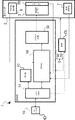
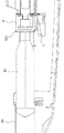
図1は注入装置1の概略斜視図であり、図2は注入装置1の概略ブロック図である。図1及び図2に示すように、薬液を注入するための注入装置1は、薬液が充填されたシリンジ91が搭載される注入ヘッド2と、注入ヘッド2に設けられ、シリンジ91の後端としてピストン93の後端931(図9)を押す押圧部4と、注入ヘッド2に設けられ、後端931を非接触で検出する後端検出装置としての後端検出部7と、注入ヘッド2を制御する制御部50を有する制御装置5とを備える。
[First Embodiment]
FIG. 1 is a schematic perspective view of the injection device 1, and FIG. 2 is a schematic block diagram of the injection device 1. As shown in FIGS. 1 and 2, an injection device 1 for injecting a chemical solution is provided with an injection head 2 on which a syringe 91 filled with a chemical solution is mounted, and the injection head 2 as a rear end of the syringe 91. The pressing portion 4 that pushes the rear end 931 (FIG. 9) of the piston 93, the rear end detection portion 7 that is provided in the injection head 2 and detects the rear end 931 in a noncontact manner, and the injection head 2 And a control device 5 having a control unit 50 for controlling.

押圧部4は、シリンジ91内の薬液を送り出すために、制御部50によってピストン93の後端931を押圧して前進するように制御される。具体的に、制御部50は、注入ヘッド2に設けられた超音波モーター3を制御し、超音波モーター3が正転するときに押圧部4が前進し、超音波モーター3が逆転するときに押圧部4が後進する。また、後端検出部7は、シリンジ91の後端として、ピストン93の後端931を検出する。   The pressing unit 4 is controlled to advance by pressing the rear end 931 of the piston 93 by the control unit 50 in order to send out the chemical solution in the syringe 91. Specifically, the control unit 50 controls the ultrasonic motor 3 provided in the injection head 2. When the ultrasonic motor 3 rotates forward, the pressing unit 4 moves forward and when the ultrasonic motor 3 rotates reversely. The pressing part 4 moves backward. Further, the rear end detection unit 7 detects the rear end 931 of the piston 93 as the rear end of the syringe 91.

さらに、注入装置1は、シリンジ91を注入ヘッド2に搭載するためのアダプタ8と、アダプタ8を検出するアダプタ検出装置としてのアダプタ検出部6とを備える。このアダプタ8は、シリンジ91を搭載するためのシリンジホルダー92に取り付けられる。   Furthermore, the injection device 1 includes an adapter 8 for mounting the syringe 91 on the injection head 2 and an adapter detection unit 6 as an adapter detection device for detecting the adapter 8. This adapter 8 is attached to a syringe holder 92 for mounting the syringe 91.

また、注入装置1は、撮像装置(不図示)に有線又は無線接続されている。そして、薬液の注入時及び画像の撮影時には、撮像装置と注入装置1との間で各種データが送受信される。例えば、注入装置1において撮像条件が設定又は表示されてもよく、撮像装置において注入条件が設定又は表示されてもよい。このような撮像装置としては、例えば、MRI(Magnetic Resonance Imaging)装置、CT(Computed Tomography)装置、アンギオ撮像装置、PET(Positron Emission Tomography)装置、SPECT(Single Photon Emission Computed Tomography)装置、CTアンギオ装置、MRアンギオ装置、超音波診断装置、血管撮像装置等の各種医療用撮像装置がある。   The injection device 1 is wired or wirelessly connected to an imaging device (not shown). Various types of data are transmitted and received between the imaging device and the injection device 1 when the chemical solution is injected and when an image is taken. For example, the imaging conditions may be set or displayed on the injection device 1, and the injection conditions may be set or displayed on the imaging device. Examples of such an imaging apparatus include an MRI (Magnetic Resonance Imaging) apparatus, a CT (Computed Tomography) apparatus, an angio imaging apparatus, a PET (Positron Emission Tomography) apparatus, a SPECT (Single Photon Emission Computed Tomography) apparatus, and a CT angio apparatus. There are various medical imaging devices such as MR angio devices, ultrasonic diagnostic devices, and blood vessel imaging devices.

また、注入装置1は、薬液の注入状況等が表示されるディスプレイとしてのタッチパネルを有するコンソール10と、制御部50と注入ヘッド2の電源55とを有する制御装置5とを備えている。このコンソール10、制御装置5及び注入ヘッド2のそれぞれは、互いに有線接続又は無線接続することができる。例えば、それぞれがメタルケーブル12及び光ケーブル13等を介して有線接続されてもよく、また2.4GHz〜5GHzの周波数帯を使用する無線方式で無線接続されてもよい。また、ハンドスイッチ14等の遠隔操作装置が、コンソール10に有線又は無線接続されてもよい。なお、遠隔操作装置が注入ヘッド2に有線又は無線接続されて、薬液注入をスタート又はストップさせることもできる。   Further, the injection device 1 includes a console 10 having a touch panel as a display for displaying a medical solution injection status and the like, and a control device 5 having a control unit 50 and a power supply 55 of the injection head 2. Each of the console 10, the control device 5, and the injection head 2 can be connected to each other by wire or wireless. For example, each may be connected by wire via the metal cable 12 and the optical cable 13 or the like, or may be wirelessly connected by a wireless method using a frequency band of 2.4 GHz to 5 GHz. A remote control device such as the hand switch 14 may be connected to the console 10 by wire or wirelessly. The remote control device can be connected to the injection head 2 by wire or wirelessly to start or stop the chemical solution injection.

制御装置5と注入ヘッド2は、キャスタースタンド11と一体的に構成することができる。また、それぞれをばらばらに設け、キャスタースタンド11に搭載することもできる。なお、キャスタースタンド11に代えて天吊部材を設け、この天吊部材を介して天井から注入ヘッド2を天吊することもできる。また、電源55は、注入ヘッド2又はコンソール10に設けることもでき、独立した電源55を別途設けることもできる。さらに、電源55はバッテリーに代えることもできる。   The control device 5 and the injection head 2 can be configured integrally with the caster stand 11. Moreover, each can be provided separately and mounted on the caster stand 11. In addition, it replaces with the caster stand 11, a ceiling suspension member is provided, and the injection head 2 can also be suspended from the ceiling via this ceiling suspension member. Further, the power source 55 can be provided in the injection head 2 or the console 10, and an independent power source 55 can be provided separately. Furthermore, the power source 55 can be replaced with a battery.

また、コンソール10には、動作パターン(注入プロトコル)のデータ、及び薬液のデータ等が予め記憶されている。患者に薬液を注入する場合、オペレーターは、タッチパネル又は入力ボタンを操作して、注入速度、注入量、注入時間及び注入最大圧力などの注入プロトコル、体重、身長、体表面積、心拍数及び心拍出量などの患者の身体的データ、及び薬液の種類のデータ等を入力する。そして、コンソール10は、入力されたデータと予め記憶されているデータに応じて、最適な注入条件を算出する。その後、コンソール10は、算出された注入条件に基づいて、患者に注入する薬液の量及び注入プロトコルを決定する。   In addition, the operation pattern (infusion protocol) data, drug solution data, and the like are stored in the console 10 in advance. When injecting medicinal solution into the patient, the operator operates the touch panel or input buttons to inject the injection protocol such as infusion rate, infusion volume, infusion time and maximum infusion pressure, weight, height, body surface area, heart rate and cardiac output. Enter the patient's physical data such as the amount, and the data of the type of medicinal solution. Then, the console 10 calculates optimal injection conditions according to the input data and data stored in advance. Thereafter, the console 10 determines the amount of the drug solution to be injected into the patient and the injection protocol based on the calculated injection conditions.

さらに、コンソール10は、薬液の注入量、注入速度及び注入最大圧力などの注入プロトコルを決定すると制御装置5に送信する。制御装置5は、受信した注入プロトコルを一時的に記憶する。そして、所定のデータ又はグラフなどが、コンソール10のタッチパネル又は表示部、及び注入ヘッド2のヘッドディスプレイ(不図示)の少なくとも一方に表示される。また、データ又はグラフなどは、ポータブルディスプレイ又はタブレット型コンピューター等に表示させることもできる。これらのデバイスは、注入ヘッド2又は制御装置5とBluetooth(登録商標)及びWi-Fi等の規格に従い無線接続され、注入ヘッド2のヘッドディスプレイに代えることもできる。これにより、オペレーターは、表示されたデータ又はグラフなどを確認することができる。なお、動作パターン(注入プロトコル)のデータ及び薬液のデータ等は、外部の記憶媒体から入力することもできる。また、制御装置5は、超音波モーター3に接続されており、超音波モーター3にはエンコーダー39が接続されている。そして、エンコーダー39は、超音波モーター3の回転速度に対応する周波数のパルス信号を制御装置5に送信している。   Further, when the console 10 determines the injection protocol such as the injection amount of the chemical solution, the injection speed, and the maximum injection pressure, the console 10 transmits it to the control device 5. The control device 5 temporarily stores the received injection protocol. Predetermined data or graphs are displayed on at least one of the touch panel or display unit of the console 10 and the head display (not shown) of the injection head 2. Data or graphs can also be displayed on a portable display or tablet computer. These devices are wirelessly connected to the injection head 2 or the control device 5 in accordance with standards such as Bluetooth (registered trademark) and Wi-Fi, and can be replaced with the head display of the injection head 2. Thereby, the operator can check the displayed data or graph. Note that the operation pattern (injection protocol) data, drug solution data, and the like can be input from an external storage medium. The control device 5 is connected to the ultrasonic motor 3, and the encoder 39 is connected to the ultrasonic motor 3. The encoder 39 transmits a pulse signal having a frequency corresponding to the rotational speed of the ultrasonic motor 3 to the control device 5.

押圧部4は、不図示の駆動機構を有する。駆動機構は、超音波モーター3のシャフトに接続された伝達機構と、伝達機構に接続されたネジ軸と、ネジ軸に取り付けられた台形ネジナットと、台形ネジナットに接続されたアクチュエーターとを備える。また、伝達機構は、シャフトに接続されたピニオンギアと、ネジ軸に接続されたスクリューギアとを有している。そして、伝達機構は、超音波モーター3からの回転をネジ軸に伝達する。そのため、超音波モーター3のシャフトの回転は、ピニオンギア及びスクリューギアを介してネジ軸に伝達される。これにより、ネジ軸は、伝達された回転に従って回転する。そして、台形ネジナットは、ネジ軸の回転に伴い前進方向又は後進方向に摺動する。この台形ネジナットの摺動に伴い、押圧部4の前端部分が前進又は後進する。   The pressing part 4 has a drive mechanism (not shown). The drive mechanism includes a transmission mechanism connected to the shaft of the ultrasonic motor 3, a screw shaft connected to the transmission mechanism, a trapezoidal screw nut attached to the screw shaft, and an actuator connected to the trapezoidal screw nut. The transmission mechanism has a pinion gear connected to the shaft and a screw gear connected to the screw shaft. The transmission mechanism transmits the rotation from the ultrasonic motor 3 to the screw shaft. Therefore, the rotation of the shaft of the ultrasonic motor 3 is transmitted to the screw shaft via the pinion gear and the screw gear. Thereby, the screw shaft rotates according to the transmitted rotation. The trapezoidal screw nut slides in the forward or backward direction as the screw shaft rotates. As the trapezoidal screw nut slides, the front end portion of the pressing portion 4 moves forward or backward.

シリンジ91には、シリンジ91内において摺動可能であるピストン93が取り付けられている。そして、ピストン93の後端931が押圧部4に当接した状態で超音波モーター3が正転すると、押圧部4がピストン93を前進方向に押すことになる。そして、ピストン93が前進するとシリンジ91内の薬液が押し出され、シリンジ91の先端に接続される延長チューブ900及びミキシングデバイス910等を介して患者の体内に注入される。このミキシングデバイス910は、旋回流を生成するための旋回流生成室と、混合された薬液が流出する流出口と、旋回流生成室及び流出口の間に設けられ、流出口に向かって連続的に狭窄している空間を有する狭窄室とを備える。また、超音波モーター3が逆転すると、押圧部4がピストン93を後退方向に引くことになる。   A piston 93 slidable in the syringe 91 is attached to the syringe 91. When the ultrasonic motor 3 rotates forward with the rear end 931 of the piston 93 in contact with the pressing portion 4, the pressing portion 4 pushes the piston 93 in the forward direction. When the piston 93 moves forward, the chemical solution in the syringe 91 is pushed out and injected into the patient's body through the extension tube 900 and the mixing device 910 connected to the tip of the syringe 91. This mixing device 910 is provided between a swirl flow generation chamber for generating a swirl flow, an outflow port from which the mixed chemical solution flows out, and the swirl flow generation chamber and the outflow port, and is continuously directed toward the outflow port. And a constriction chamber having a constricted space. Further, when the ultrasonic motor 3 is reversed, the pressing portion 4 pulls the piston 93 in the backward direction.

薬液が充填されたシリンジ91は、プレフィルドシリンジであってもよい。また、薬液は、手動でシリンジ91に充填されてもよく、注入装置1や充填器でシリンジ91に充填されてもよい。さらに、シリンジ91には、RFIDやバーコードといったデーターキャリアを設けることができる。このデーターキャリアには、充填された薬液の情報等が記録されている。そして、注入装置1は、注入ヘッド2を介してデーターキャリアから記録された情報を読み取り、薬液の注入圧力等を制御することができる。例えば、制御装置5は、読み取った薬液の情報(ヨード量、ガドリニウム含有量等)に基づいて、体重当たりの最適な注入量を計算してコンソール10のタッチパネルに表示させることができる。   The syringe 91 filled with the chemical solution may be a prefilled syringe. Moreover, a chemical | medical solution may be manually filled into the syringe 91, and may be filled into the syringe 91 with the injection apparatus 1 or a filling device. Furthermore, the syringe 91 can be provided with a data carrier such as an RFID or a barcode. In this data carrier, information on the filled chemical solution is recorded. The injection device 1 can read the information recorded from the data carrier via the injection head 2 and control the injection pressure and the like of the chemical solution. For example, the control device 5 can calculate the optimum injection amount per body weight based on the read information on the chemical solution (iodine amount, gadolinium content, etc.) and display it on the touch panel of the console 10.

薬液を注入する場合、オペレーターは注入装置1の電源をオンにし、シリンジ91を搭載する。その後、オペレーターは、注入ヘッド2のスタートボタン28を押す。また、注入ヘッド2に操作パネルが設けられている場合には、オペレーターはこの操作パネルの注入ボタンを押すこともできる。さらに、オペレーターは、ハンドスイッチ14のボタン又はタッチパネルに表示された注入ボタンを押して注入を開始することもできる。なお、オペレーターは、シリンジ91を搭載した後に、注入装置1の電源をオンしてもよい。   When injecting a chemical solution, the operator turns on the power of the injection device 1 and mounts the syringe 91. Thereafter, the operator presses the start button 28 of the injection head 2. When the operation panel is provided on the injection head 2, the operator can press the injection button on the operation panel. Further, the operator can start injection by pressing a button on the hand switch 14 or an injection button displayed on the touch panel. Note that the operator may turn on the power of the injection device 1 after mounting the syringe 91.

注入ボタンが押されると、制御装置5は超音波モーター3に駆動電圧として正転信号を送る。この正転信号に応じて、超音波モーター3のシャフトが正転すると、エンコーダー39は回転を検出して制御装置5にパルス信号を送る。その後、注入が終了しシリンジ91を取り外す場合、ピストン93を後進させるために、制御装置5は超音波モーター3に駆動電圧として逆転信号を送る。この逆転信号に応じて超音波モーター3のシャフトが逆転する。超音波モーター3に送信される駆動電圧は交流であり、位相が異なる2種類の駆動電圧のうち一方が他方に対して遅れている場合を正転信号としたときに、他方が一方に対して遅れている場合が逆転信号となる。   When the injection button is pressed, the control device 5 sends a normal rotation signal as a drive voltage to the ultrasonic motor 3. When the shaft of the ultrasonic motor 3 rotates normally according to the normal rotation signal, the encoder 39 detects the rotation and sends a pulse signal to the control device 5. Thereafter, when the injection is completed and the syringe 91 is removed, the control device 5 sends a reverse signal as a drive voltage to the ultrasonic motor 3 in order to move the piston 93 backward. The shaft of the ultrasonic motor 3 reverses in response to the reverse signal. The drive voltage transmitted to the ultrasonic motor 3 is alternating current, and when one of the two types of drive voltages having different phases is delayed with respect to the other, the other is set to the other. When it is late, it becomes a reverse rotation signal.

制御装置5は記憶部としてのメモリ部53を有し、メモリ部53には注入プロトコルが記憶されている。薬液の注入は、この注入プロトコルに従って自動的に行われる。この注入プロトコルには、例えば、注入時間、注入速度、注入量及び注入圧力リミット値が設定されている。そして、注入プロトコルの内容はコンソール10に表示されるので、オペレーターは注入プロトコルの内容を確認することができる。また、制御装置5は、タイマー(不図示)を利用して注入時間を制御すると共に、薬液の注入圧力等の注入状況を監視している。なお、コンソール10に注入プロトコルが記憶された記憶媒体を接続して、記憶媒体から読み込んだ注入プロトコルに従って薬液の注入行うこともできる。また、注入プロトコルを変更できないように、パスワードによりロックすることもできる。   The control device 5 has a memory unit 53 as a storage unit, and the memory unit 53 stores an injection protocol. The injection of the chemical solution is automatically performed according to this injection protocol. In this injection protocol, for example, an injection time, an injection speed, an injection amount, and an injection pressure limit value are set. Then, since the contents of the injection protocol are displayed on the console 10, the operator can check the contents of the injection protocol. The control device 5 controls the injection time using a timer (not shown), and monitors the injection status such as the injection pressure of the chemical solution. In addition, the storage medium in which the injection protocol is stored can be connected to the console 10, and the chemical solution can be injected according to the injection protocol read from the storage medium. It can also be locked with a password so that the injection protocol cannot be changed.

注入ヘッド2及び制御装置5は、検査室内に配置できるように非磁性体材料を用いて構成されている。具体的には、ステンレス、アルミニウム、プラスチック、真鍮、銅、セラッミックス等を用いて構成されている。さらに、操作室に配置されるコンソール10も、非磁性体材料を用いて構成すれば検査室内に配置できる。また、超音波モーター3も非磁性体材料を用いて構成されている。具体的には、弾性体の材料はリン青銅であり、シャフト、ネジ及びスペーサの材料は真鍮であり、ケース、ベース及びローターの材料はアルミニウムであり、ブッシュの材料はフッ素樹脂である。これにより、MRI装置等の磁気を利用する機器の近傍で注入装置1を使用することができる。ただし、MRI装置から十分に離して使用する場合、磁気シールド処理を施した場合、又は他の撮像装置の近傍で使用する場合には、磁性体材料を用いて注入ヘッド2及び制御装置5を構成することもできる。   The injection head 2 and the control device 5 are configured using a non-magnetic material so that they can be arranged in the examination room. Specifically, it is configured using stainless steel, aluminum, plastic, brass, copper, ceramics, or the like. Furthermore, the console 10 arranged in the operation room can also be arranged in the examination room by using a non-magnetic material. The ultrasonic motor 3 is also made of a nonmagnetic material. Specifically, the material of the elastic body is phosphor bronze, the material of the shaft, screw and spacer is brass, the material of the case, base and rotor is aluminum, and the material of the bush is fluororesin. Thereby, the injection apparatus 1 can be used in the vicinity of a device using magnetism such as an MRI apparatus. However, the injection head 2 and the control device 5 are made of a magnetic material when used sufficiently away from the MRI apparatus, when a magnetic shield process is performed, or when used in the vicinity of another imaging apparatus. You can also

図2に示すように、制御装置5にはコンソール10が接続されており、制御装置5のメインCPU51は、コンソール10と信号の送受信を行う。制御装置5の制御部50は超音波モーター3を制御し、電源55は制御部50及び注入ヘッド2に電力を供給する。また、制御部50のメインCPU(制御ユニット)51は、ワンチップマイコンからなり、予めメモリ部53に記憶されたプログラムに応じて、超音波モーター3の制御の他、所定の演算、制御、判別などの処理動作を実行する。メモリ部53は、メインCPU(Central Processing Unit)が動作するためのシステムワークメモリであるRAM(Random Access Memory)、プログラム又はシステムソフトウェア等を格納するROM(Read Only Memory)、又はハードディスクドライブ等を備える。   As shown in FIG. 2, a console 10 is connected to the control device 5, and the main CPU 51 of the control device 5 transmits and receives signals to and from the console 10. The control unit 50 of the control device 5 controls the ultrasonic motor 3, and the power supply 55 supplies power to the control unit 50 and the injection head 2. The main CPU (control unit) 51 of the control unit 50 is composed of a one-chip microcomputer, and in addition to controlling the ultrasonic motor 3 according to a program stored in the memory unit 53 in advance, predetermined calculation, control, and determination Execute processing operations such as The memory unit 53 includes a RAM (Random Access Memory) that is a system work memory for operating a main CPU (Central Processing Unit), a ROM (Read Only Memory) that stores programs or system software, a hard disk drive, and the like. .

メインCPU51は、FPGA(Field-Programmable Gate Array)56との間で信号の送受信を行う。このFPGA56は、ドライブ回路(駆動電圧生成ユニット)52に接続され、ドライブ回路52は、超音波モーター3に接続されている。そして、超音波モーター3のローターには、超音波モーター3の回転速度に対応するパルス信号を出力するエンコーダー39が接続されている。このエンコーダー39は、FPGA56にパルス信号を出力する。   The main CPU 51 transmits and receives signals to and from an FPGA (Field-Programmable Gate Array) 56. The FPGA 56 is connected to a drive circuit (drive voltage generation unit) 52, and the drive circuit 52 is connected to the ultrasonic motor 3. The rotor of the ultrasonic motor 3 is connected to an encoder 39 that outputs a pulse signal corresponding to the rotational speed of the ultrasonic motor 3. The encoder 39 outputs a pulse signal to the FPGA 56.

注入を開始するための指令信号を受信したメインCPU51は、FPGA56へ設定速度信号を出力する。この設定速度信号に基づいて、FPGA56は、駆動電圧を生成するための駆動信号としてのsin生成信号、-sin生成信号、cos生成信号及び-cos生成信号を生成する。そして、FPGA56は、この駆動信号をドライブ回路52へ出力する。さらに、駆動信号等を受信したドライブ回路52は、超音波モーター3を駆動する駆動電圧としてのAC(Alternating Current)電圧(sin波、cos波)を生成して、超音波モーター3へ出力する。   Receiving the command signal for starting the injection, the main CPU 51 outputs a set speed signal to the FPGA 56. Based on the set speed signal, the FPGA 56 generates a sin generation signal, a −sin generation signal, a cos generation signal, and a −cos generation signal as drive signals for generating a drive voltage. Then, the FPGA 56 outputs this drive signal to the drive circuit 52. Further, the drive circuit 52 that has received the drive signal or the like generates an AC (Alternating Current) voltage (sin wave, cos wave) as a drive voltage for driving the ultrasonic motor 3, and outputs it to the ultrasonic motor 3.

なお、超音波モーター3と制御部50とが一体的に設けられた駆動装置を注入装置1が備え、この駆動装置によって押圧部4を駆動することもできる。また、制御部50は、コンソール10と一体的に設けることもできる。   In addition, the injection device 1 includes a driving device in which the ultrasonic motor 3 and the control unit 50 are integrally provided, and the pressing unit 4 can be driven by the driving device. In addition, the control unit 50 can be provided integrally with the console 10.

[アダプタ検出装置]
図1のシリンジホルダー92には、シリンジ91を注入ヘッド2に搭載すると共に、凸部83(図4)が設けられたアダプタ8が取り付けられる。そして、注入ヘッド2には、アダプタ検出装置として、アダプタ8を検出するアダプタ検出部6(図5)が設けられている。
[Adapter detection device]
1 is mounted with the syringe 91 on the injection head 2 and the adapter 8 provided with the convex portion 83 (FIG. 4). The injection head 2 is provided with an adapter detection unit 6 (FIG. 5) that detects the adapter 8 as an adapter detection device.

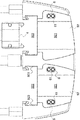
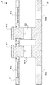
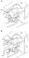
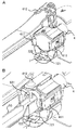
以下、図3〜7を参照してアダプタ検出部6について説明する。図3は、アダプタ8を取り付ける前の注入ヘッド2の前端部分を示す概略上面図である。また、図4A及び図4Bは、アダプタの一例として造影剤側のシリンジホルダー92に取り付け可能なアダプタ8を示す。なお、図4Aは上方から見たアダプタ8を示す概略斜視図であり、図4Bは外方から見たアダプタ8を示す概略側面図である。また、図5は、下方から見たアダプタ検出部6を示す概略斜視図である。また、図6はアダプタ検出部6を長手方向(前後方向)に切断した概略断面図である。また、図7は、固定されたアダプタ検出部6を長手方向に切断した概略断面図である。   Hereinafter, the adapter detection unit 6 will be described with reference to FIGS. FIG. 3 is a schematic top view showing the front end portion of the injection head 2 before the adapter 8 is attached. 4A and 4B show an adapter 8 that can be attached to a contrast-agent-side syringe holder 92 as an example of an adapter. 4A is a schematic perspective view showing the adapter 8 viewed from above, and FIG. 4B is a schematic side view showing the adapter 8 viewed from the outside. FIG. 5 is a schematic perspective view showing the adapter detection unit 6 as viewed from below. FIG. 6 is a schematic cross-sectional view of the adapter detection unit 6 cut in the longitudinal direction (front-rear direction). FIG. 7 is a schematic cross-sectional view of the fixed adapter detector 6 cut in the longitudinal direction.

図3に示すように、アダプタ検出部6はシリンジホルダー92の前側上部に設けられている。そして、アダプタ検出部6は、シリンジホルダー92に取り付けられるアダプタ8を検出する。2つのシリンジホルダー92の一方には、造影剤が充填されたシリンジ91が搭載される。そして、このシリンジホルダー92には、アダプタ8が挿入される凹部を挟んで両側にアダプタ検出部6が設けられている。また、他方のシリンジホルダー92には、生理食塩水が充填されたシリンジ91が搭載される。そして、このシリンジホルダー92には、アダプタ8が挿入される凹部に対して外側であり、造影剤側のシリンジホルダー92とは反対の側に1つのアダプタ検出部6が設けられている。   As shown in FIG. 3, the adapter detection unit 6 is provided on the upper front side of the syringe holder 92. The adapter detection unit 6 detects the adapter 8 attached to the syringe holder 92. A syringe 91 filled with a contrast agent is mounted on one of the two syringe holders 92. And this syringe holder 92 is provided with the adapter detection part 6 on both sides across the recessed part where the adapter 8 is inserted. The other syringe holder 92 is mounted with a syringe 91 filled with physiological saline. The syringe holder 92 is provided with one adapter detector 6 on the side opposite to the contrast medium side of the syringe holder 92 that is outside the recess into which the adapter 8 is inserted.

各アダプタ検出部6は、アダプタ8に設けられた凸部83により押し下げられるシリコンゴム製のボタン61を有する。造影剤側のシリンジホルダー92には、2つのボタン61が設けられている。また、生理食塩水側のシリンジホルダー92には、1つのボタン61が設けられている。   Each adapter detection unit 6 has a button 61 made of silicon rubber that is pushed down by a convex portion 83 provided on the adapter 8. Two buttons 61 are provided on the syringe holder 92 on the contrast medium side. Moreover, one button 61 is provided on the syringe holder 92 on the physiological saline side.

シリンジ91は、外形及び材質(ガラス又は樹脂等)の少なくとも一方が製造会社毎に異なることがある。そのため、複数種類の外形のシリンジ91をシリンジホルダー92に搭載させるために、アダプタ8が用いられる。このアダプタ8は、シリンジホルダー92に取り付けられ、取り付けられたアダプタ8にシリンジ91が搭載される。これにより、シリンジ91が注入ヘッド2に搭載される。シリンジ91の外形に応じて異なるアダプタ8を用いることにより、複数種類のシリンジ91を搭載することができる。   The syringe 91 may have different outer shapes and / or materials (glass or resin) for each manufacturer. Therefore, the adapter 8 is used in order to mount the syringe 91 having a plurality of types of external shapes on the syringe holder 92. The adapter 8 is attached to a syringe holder 92, and a syringe 91 is mounted on the attached adapter 8. Thereby, the syringe 91 is mounted on the injection head 2. By using different adapters 8 according to the outer shape of the syringe 91, a plurality of types of syringes 91 can be mounted.

図4Aに示すように、アダプタ8は、シリンジ91が搭載される凹部81と、凹部81から外側に向かって延在するフランジ82と、フランジ82の下側に設けられた凸部83とを有する。この凹部81は略U字状に湾曲し、シリンジホルダー92の略U字状に湾曲した溝921に挿入されると共に、シリンジ91の外形と相補的な内面形状を有する。また、図4Bに示すように、凹部81には、シリンジ91を外部から観察するための窓部811が設けられている。なお、凸部83は両フランジ82に設けられているが、両フランジ82の一方にのみ凸部83が設けられていてもよい。   As shown in FIG. 4A, the adapter 8 has a concave portion 81 in which the syringe 91 is mounted, a flange 82 extending outward from the concave portion 81, and a convex portion 83 provided on the lower side of the flange 82. . The concave portion 81 is curved in a substantially U shape, is inserted into a substantially U-shaped groove 921 of the syringe holder 92, and has an inner surface shape complementary to the outer shape of the syringe 91. As shown in FIG. 4B, the recess 81 is provided with a window portion 811 for observing the syringe 91 from the outside. In addition, although the convex part 83 is provided in both the flanges 82, the convex part 83 may be provided only in one of the both flanges 82. FIG.

アダプタ8は、フランジ82の上面に設けられて水平方向に回転自在である保持部材84としてのストッパーアームをさらに有する。この保持部材84は、凹部81の上方の開口から退避した退避位置と、この開口に突出した保持位置との間で移動することができる。また、保持部材84はレバー部842を有しており、保持部材84が保持位置に向かって回転すると、レバー部842がストッパー841に当接して回転が停止する。そして、保持位置に位置する保持部材84は、凹部81に位置するシリンジ91の外面に上方から当接する。これにより、シリンジ91は、下方の凹部81及び上方の保持部材84により確実に保持される。   The adapter 8 further includes a stopper arm as a holding member 84 that is provided on the upper surface of the flange 82 and is rotatable in the horizontal direction. The holding member 84 can move between a retracted position retracted from the opening above the recess 81 and a holding position protruding from the opening. The holding member 84 has a lever portion 842. When the holding member 84 rotates toward the holding position, the lever portion 842 contacts the stopper 841 and stops rotating. And the holding member 84 located in a holding position contacts the outer surface of the syringe 91 located in the recessed part 81 from upper direction. Thereby, the syringe 91 is reliably held by the lower concave portion 81 and the upper holding member 84.

アダプタ8の後部には、弾性を有する係合部85が設けられている。そして、シリンジホルダー92には、係合部85を受け入れる係合溝922が設けられており、係合溝922は溝921と連通している。また、係合部85の外面には隆起部851が設けられており、係合溝922の内面には内方に向かって突出する規制部923が設けられている。また、係合部85の上端にはつまみ部852が設けられている。   An engaging portion 85 having elasticity is provided at the rear portion of the adapter 8. The syringe holder 92 is provided with an engagement groove 922 that receives the engagement portion 85, and the engagement groove 922 communicates with the groove 921. A raised portion 851 is provided on the outer surface of the engaging portion 85, and a restricting portion 923 that protrudes inward is provided on the inner surface of the engaging groove 922. Further, a knob portion 852 is provided at the upper end of the engaging portion 85.

オペレーターが内方に向かう力をつまみ部852に加えると、両つまみ部852が互いに近付くように係合部85が変形する。これにより、係合部85の外寸が変化するので、隆起部851が規制部923を乗り越えるように、係合部85を係合溝922に挿入することができる。その後、オペレーターがつまみ部852を離すと、係合部85の変形が解消され、隆起部851は規制部923の下方に位置する。これにより、アダプタ8の上方への移動は、規制部923によって規制される。また、係合部85の変形が解消される際に、係合部85の外面が係合溝922と衝突し衝突音を生じさせる。この衝突音を確認することにより、オペレーターはアダプタ8が正常に取り付けられたことを確認することができる。   When the operator applies an inward force to the knob portion 852, the engaging portion 85 is deformed so that both knob portions 852 are close to each other. Thereby, since the outer dimension of the engaging part 85 changes, the engaging part 85 can be inserted into the engaging groove 922 so that the raised part 851 gets over the restricting part 923. Thereafter, when the operator releases the knob portion 852, the deformation of the engaging portion 85 is eliminated, and the raised portion 851 is positioned below the restricting portion 923. Thereby, the upward movement of the adapter 8 is regulated by the regulation unit 923. Further, when the deformation of the engaging portion 85 is eliminated, the outer surface of the engaging portion 85 collides with the engaging groove 922 to generate a collision sound. By confirming this collision sound, the operator can confirm that the adapter 8 has been normally attached.

図4Bに示すように、フランジ82の上面と係合部85の上面とは、同一平面を構成している。そして、フランジ82の上面から凸部83の下端までの長さは、係合部85の上面から隆起部851の下端までの長さよりも短い。そのため、アダプタ8が取り付けられる前、すなわち、隆起部851が規制部923を乗り越える前は、凸部83がアダプタ検出部6のボタン61に当接しない。これにより、アダプタ8が正常に取り付けられる前に、誤ってアダプタ8が検出されてしまうことを抑制することができる。   As shown in FIG. 4B, the upper surface of the flange 82 and the upper surface of the engaging portion 85 constitute the same plane. The length from the upper surface of the flange 82 to the lower end of the convex portion 83 is shorter than the length from the upper surface of the engaging portion 85 to the lower end of the raised portion 851. Therefore, before the adapter 8 is attached, that is, before the raised portion 851 gets over the restricting portion 923, the convex portion 83 does not contact the button 61 of the adapter detecting portion 6. Thereby, before the adapter 8 is normally attached, it can suppress that the adapter 8 will be detected accidentally.

なお、図4A及び図4Bに示すアダプタ8は一例であり、注入ヘッド2には他の形状のアダプタ8を取り付けることもできる。例えば、保持部材84及びつまみ部852の、いずれか一方のみを有するアダプタ8を注入ヘッド2に取り付けることもできる。また、保持部材84及びつまみ部852を有さないアダプタ8を注入ヘッド2に取り付けることができる。   The adapter 8 shown in FIGS. 4A and 4B is an example, and the adapter 8 having another shape can be attached to the injection head 2. For example, the adapter 8 having only one of the holding member 84 and the knob portion 852 can be attached to the injection head 2. Further, the adapter 8 that does not have the holding member 84 and the knob portion 852 can be attached to the injection head 2.

図5及び図6に示すように、アダプタ検出部6は、アダプタ8の凸部83により押し下げられるボタン61と、ボタン61の押し下げを非接触で検出するセンサー62とを有している。このセンサー62は、複数のボタン61の下方に対向配置され、押し下げられたボタン61を非接触で検出する光学式のスリットセンサーである。   As shown in FIGS. 5 and 6, the adapter detection unit 6 includes a button 61 that is pushed down by the convex portion 83 of the adapter 8 and a sensor 62 that detects the depression of the button 61 in a non-contact manner. The sensor 62 is an optical slit sensor that is disposed to face the lower side of the plurality of buttons 61 and detects the pressed button 61 in a non-contact manner.

具体的に、ボタン61は、凸部83に当接する2つの当接部611を有し、当接部611は凸部83に押し下げられると下方に突出するように変形する。また、アダプタ8が取り外され、凸部83が当接部611から離れると、当接部611は自身の弾性力によって元の形状に復帰する。センサー62は、互いに対向する発光部621と受光部622とを有しており、当接部611により光が遮られるとアダプタ8(ボタン61の押し下げ)を検出する。これにより、非接触でボタン61の押し下げを検出できるため、ボタン61とセンサー62の接触に起因する経年劣化を防止できる。   Specifically, the button 61 has two abutting portions 611 that abut against the convex portion 83, and the abutting portion 611 is deformed so as to protrude downward when pushed down by the convex portion 83. When the adapter 8 is removed and the convex portion 83 is separated from the contact portion 611, the contact portion 611 returns to its original shape by its own elastic force. The sensor 62 includes a light emitting unit 621 and a light receiving unit 622 that are opposed to each other. When the light is blocked by the contact unit 611, the sensor 8 detects the adapter 8 (the button 61 is pressed down). As a result, the depression of the button 61 can be detected in a non-contact manner, so that it is possible to prevent aged deterioration due to the contact between the button 61 and the sensor 62.

また、ボタン61は長手方向に並んだ2つの穴部612を有し、センサー62は穴部612と対向するねじ穴623を有する。そして、図7に示すように、ボタン61は、注入ヘッド2のフレーム21の内側に固定されている。具体的には、フレーム21から下方に突出する固定部22を穴部612に挿入し、ボタン61をフレーム21の内側に取り付ける。そして、ボタン61とセンサー62との間に押さえ部材23を配置する。その後、ねじ穴623を介して、センサー62をねじ624により固定部22に固定する。固定されたボタン61の当接部611上面は、フレーム21に設けられた穴を介して外部に露出する。なお、図7においては、上側がフレーム21の外側に対応する。   The button 61 has two holes 612 aligned in the longitudinal direction, and the sensor 62 has a screw hole 623 facing the hole 612. As shown in FIG. 7, the button 61 is fixed inside the frame 21 of the injection head 2. Specifically, the fixing part 22 protruding downward from the frame 21 is inserted into the hole 612, and the button 61 is attached to the inside of the frame 21. Then, the pressing member 23 is disposed between the button 61 and the sensor 62. Thereafter, the sensor 62 is fixed to the fixing portion 22 with the screw 624 through the screw hole 623. The upper surface of the contact portion 611 of the fixed button 61 is exposed to the outside through a hole provided in the frame 21. In FIG. 7, the upper side corresponds to the outside of the frame 21.

このようにボタン61を内側から固定することにより、ボタン61がフレーム21から外れることを防止できる。また、ボタン61は防水性の材料から形成されている。そのため、薬液が漏れた場合であっても、フレーム21内への薬液の進入をボタン61により抑制できる。   By fixing the button 61 from the inside in this way, it is possible to prevent the button 61 from being detached from the frame 21. The button 61 is made of a waterproof material. Therefore, even if the chemical liquid leaks, the button 61 can suppress the chemical liquid from entering the frame 21.

[アダプタの検出]
続いて、図2を参照して、アダプタ検出部6によるアダプタ8の検出について説明する。アダプタ8は、搭載可能なシリンジ種類に応じて、凸部83の配置パターンが異なる。例えば、両側にそれぞれ2つの凸部83(合計4つの凸部83)を有するアダプタにはA社が製造したシリンジを搭載できるが、B社が製造したシリンジは搭載できない。一方、両側にそれぞれ1つの凸部83(合計2つの凸部83)を有するアダプタにはB社が製造したシリンジを搭載できるが、A社が製造したシリンジは搭載できない。そのため、アダプタ8を検出すると、凸部83の配置パターンに基づいてアダプタ8の種類を判定することができる。
[Detect Adapter]
Next, detection of the adapter 8 by the adapter detection unit 6 will be described with reference to FIG. The adapter 8 has a different arrangement pattern of the protrusions 83 depending on the type of syringe that can be mounted. For example, a syringe manufactured by Company A can be mounted on an adapter having two protrusions 83 on each side (four protrusions 83 in total), but a syringe manufactured by Company B cannot be mounted. On the other hand, a syringe manufactured by Company B can be mounted on an adapter having one convex portion 83 (two convex portions 83 in total) on both sides, but a syringe manufactured by Company A cannot be mounted. Therefore, when the adapter 8 is detected, the type of the adapter 8 can be determined based on the arrangement pattern of the convex portions 83.

具体的にアダプタ検出部6のセンサー62は、凸部83により押し下げられた当接部611を検出した場合は、検出信号(ON信号)を制御部50に送信する。例えば、センサー62は、両側にそれぞれ2つの当接部611を検出したことを示す検出信号を制御部50に送信する。そして、制御部50は、検出された当接部611の配置パターンをメモリ部53に記憶させる。また、アダプタ8が取り外され、当接部611を検出しない場合、センサー62は非検出信号を制御部50に送信する。   Specifically, when the sensor 62 of the adapter detection unit 6 detects the contact portion 611 pushed down by the convex portion 83, the sensor 62 transmits a detection signal (ON signal) to the control unit 50. For example, the sensor 62 transmits a detection signal indicating that the two contact portions 611 are detected on both sides to the control unit 50. Then, the control unit 50 stores the detected arrangement pattern of the contact portions 611 in the memory unit 53. When the adapter 8 is removed and the contact portion 611 is not detected, the sensor 62 transmits a non-detection signal to the control unit 50.

検出信号は、FPGA56を介してメインCPU51に送信される。そして、制御部50のFPGA56及びメモリ部53の少なくとも一方には、予め凸部83の配置パターンとアダプタ8の種類とを対応させたデータテーブルが記憶されている。制御部50は、このデータテーブルを参照し、アダプタ8の種類を判定して判定結果を一時的に記憶する。これにより、制御部50は、注入ヘッド2に取り付けられたアダプタ8の種類を取得することができる。   The detection signal is transmitted to the main CPU 51 via the FPGA 56. At least one of the FPGA 56 and the memory unit 53 of the control unit 50 stores a data table in which the arrangement pattern of the protrusions 83 is associated with the type of the adapter 8 in advance. The control unit 50 refers to this data table, determines the type of the adapter 8, and temporarily stores the determination result. Thereby, the control unit 50 can acquire the type of the adapter 8 attached to the injection head 2.

このアダプタ8の種類は、シリンジ種類に対応している。そして、FPGA56及びメモリ部53の少なくとも一方には、アダプタ8の種類に対応するシリンジ種類が予め記憶されている。これにより、制御部50は、シリンジ種類を判定することができる。例えば、両側にそれぞれ2つの凸部83を有するアダプタ8であると判定された場合、制御部50は、搭載されるシリンジ種類をA社が製造したシリンジであると判定し、種類を一時的に記憶する。同時に、制御部50は、シリンジ種類としてA社のシリンジであることをコンソール10に表示させる。なお、製造会社に代えて又は製造会社と共に、シリンジ種類として薬剤名をコンソール10に表示させてもよい。   The type of the adapter 8 corresponds to the syringe type. At least one of the FPGA 56 and the memory unit 53 stores a syringe type corresponding to the type of the adapter 8 in advance. Thereby, the control part 50 can determine a syringe kind. For example, when it is determined that the adapter 8 has two convex portions 83 on both sides, the control unit 50 determines that the syringe type to be mounted is a syringe manufactured by Company A, and temporarily sets the type. Remember. Simultaneously, the control part 50 displays on the console 10 that it is a syringe of A company as a syringe kind. Note that the medicine name may be displayed on the console 10 as the syringe type instead of or together with the manufacturer.

アダプタ8の種類に対応させて予め記憶させる情報としては、製造会社、後端検出時の前進距離、後端までの推定距離、製品名称、薬剤名、製品ID、化学分類、含有成分、濃度、粘度、シリンジ容量、シリンジ耐圧、シリンダ内径及びピストンストローク等がある。これらの情報を予め記憶しておくことにより、制御部50は、各種判定を行うことができる。例えば、両側にそれぞれ2つの凸部83を有するアダプタ8であると判定された場合、制御部50は、後端検出時の前進距離を判定することができる。   Information stored in advance corresponding to the type of the adapter 8 includes the manufacturer, the advance distance when detecting the rear end, the estimated distance to the rear end, the product name, the drug name, the product ID, the chemical classification, the contained component, the concentration, There are viscosity, syringe capacity, syringe pressure resistance, cylinder inner diameter, piston stroke and the like. By storing these pieces of information in advance, the control unit 50 can make various determinations. For example, when it is determined that the adapter 8 has two convex portions 83 on both sides, the control unit 50 can determine the advance distance when the rear end is detected.

凸部83の配置パターンは適宜設計することができるが、アダプタ8の片側にのみ凸部83を設ける場合には、1つのみの凸部83を設けることが好ましい。アダプタ8の片側に2つの凸部83を設けてボタン61を押し下げた場合、当接部611の弾性力(復帰力)でアダプタ8の片側が押し上げられる可能性がある。アダプタ8の片側が押し上げられるとアダプタ8が傾いてしまい、当接部611を正確に検出できない可能性がある。そのため、片側のみに凸部83を設ける場合には、1つの凸部83のみを設けることにより、アダプタ8が受ける力を最小限に抑え傾きを抑制することができる。特に、造影剤のシリンジ91は軽いため、このシリンジ91を搭載するためのアダプタ8の片側にのみ凸部83を設ける場合には、1つのみの凸部83を設けることが好ましい。   The arrangement pattern of the projections 83 can be designed as appropriate, but when the projections 83 are provided only on one side of the adapter 8, it is preferable to provide only one projection 83. When the two convex portions 83 are provided on one side of the adapter 8 and the button 61 is pushed down, the one side of the adapter 8 may be pushed up by the elastic force (return force) of the contact portion 611. When one side of the adapter 8 is pushed up, the adapter 8 tilts, and the contact portion 611 may not be detected accurately. Therefore, when providing the convex part 83 only on one side, by providing only one convex part 83, the force received by the adapter 8 can be minimized and the inclination can be suppressed. In particular, since the contrast agent syringe 91 is light, when the convex portion 83 is provided only on one side of the adapter 8 for mounting the syringe 91, it is preferable to provide only one convex portion 83.

アダプタ8が取り外され、アダプタ検出部6から非検出信号を受信した制御部50は、一時的にメモリ部53に記憶した配置パターンをリセットさせ、次のアダプタ8の取り付けに備える。この時、制御部50は、当接部611の全ての非検出信号受信した場合に、メモリ部53に配置パターンをリセットさせる。例えば、両側にそれぞれ2つの当接部611含む配置パターンが記憶されていた場合、制御部50は、4つの当接部611の全てが検出されなくなるまでリセットを行わない。これにより、取り付けられたアダプタ8が誤って傾いてしまい、一部の当接部611が検出されなくなった場合でも、制御部50はリセットを行わない。そのため、制御部50が、アダプタ8の取り外しを誤って判断することを抑制できる。   When the adapter 8 is removed and the non-detection signal is received from the adapter detection unit 6, the control unit 50 temporarily resets the arrangement pattern stored in the memory unit 53 and prepares for the next attachment of the adapter 8. At this time, the control unit 50 causes the memory unit 53 to reset the arrangement pattern when all the non-detection signals of the contact unit 611 are received. For example, when an arrangement pattern including two contact portions 611 is stored on both sides, the control unit 50 does not reset until all four contact portions 611 are not detected. Thereby, even when the attached adapter 8 is inclined by mistake and a part of the contact portions 611 is not detected, the control unit 50 does not reset. Therefore, it can suppress that the control part 50 judges the removal of the adapter 8 accidentally.

なお、ボタン61の当接部611は2つに限定されず、1つ又は3つ以上の当接部611を設けることもできる。これに対応して、アダプタ8にも1つ又は6つ以上の凸部83を設けることができる。さらに、ボタン61の数も限定されず、1つ又は3つ以上のボタン61を設けることもできる。   Note that the number of contact portions 611 of the button 61 is not limited to two, and one or three or more contact portions 611 may be provided. Correspondingly, the adapter 8 can also be provided with one or six or more convex portions 83. Further, the number of buttons 61 is not limited, and one or three or more buttons 61 can be provided.

[後端検出装置]
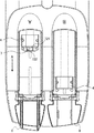
注入ヘッド2には、シリンジ91の後端931を非接触で検出する後端検出装置として、後端検出部7が設けられている。以下、図8〜10を参照して後端検出部7について説明する。図8は、注入ヘッド2の前側部分を示す概略上面図である。なお、図8の左側の押圧部4は完全に後退した位置にあり、図8の右側の押圧部4は完全に前進した位置にある。図9は、後端検出部7及びピストン93を長手方向(前後方向)に切断した概略断面図である。また、図10Aは後端931を保持していない押圧部4を示し、図10Bは後端931を保持している押圧部4を示す。また、図11Aは後端931を保持していない押圧部4を示し、図11Bは後端931を保持している押圧部4を示す。
[Rear edge detection device]
The injection head 2 is provided with a rear end detection unit 7 as a rear end detection device that detects the rear end 931 of the syringe 91 in a non-contact manner. Hereinafter, the rear end detection unit 7 will be described with reference to FIGS. FIG. 8 is a schematic top view showing the front portion of the injection head 2. 8 is in a fully retracted position, and the right pressing part 4 in FIG. 8 is in a fully advanced position. FIG. 9 is a schematic cross-sectional view of the rear end detection unit 7 and the piston 93 cut in the longitudinal direction (front-rear direction). 10A shows the pressing portion 4 that does not hold the rear end 931, and FIG. 10B shows the pressing portion 4 that holds the rear end 931. 11A shows the pressing portion 4 that does not hold the rear end 931, and FIG. 11B shows the pressing portion 4 that holds the rear end 931.

図8及び図9に示すように、後端検出部7は、発光部721と受光部722とを有する光学式のセンサーである。また、後端検出部7を保持する保持部としても機能する押圧部4が、後端検出部7を保持している。具体的に、後端検出部7は、発光部721と受光部722とが押圧部4の前方に突出するように押圧部4の下部に保持されている。そして、発光部721から出射された可視光は、ピストン93の後端931で反射されて受光部722に入射する。なお、可視光に代えて、赤外光等の他の波長の光を用いることもできる。   As shown in FIGS. 8 and 9, the rear end detection unit 7 is an optical sensor having a light emitting unit 721 and a light receiving unit 722. In addition, the pressing unit 4 that also functions as a holding unit that holds the rear end detection unit 7 holds the rear end detection unit 7. Specifically, the rear end detection unit 7 is held at the lower part of the pressing unit 4 such that the light emitting unit 721 and the light receiving unit 722 protrude in front of the pressing unit 4. The visible light emitted from the light emitting unit 721 is reflected by the rear end 931 of the piston 93 and enters the light receiving unit 722. Note that light of other wavelengths such as infrared light can be used instead of visible light.

発光部721と受光部722とは、図8の矢印Aで示す押圧部4の前進方向に対して直交する方向に並んで配置されている。これにより、押圧部4が前進している状態であっても、受光部722に確実に反射光を入射させることができる。そのため、後端検出部7は、後端931を確実に検出することができる。   The light emitting unit 721 and the light receiving unit 722 are arranged side by side in a direction orthogonal to the forward direction of the pressing unit 4 indicated by an arrow A in FIG. Thereby, even if the pressing part 4 is moving forward, the reflected light can be reliably incident on the light receiving part 722. Therefore, the rear end detection unit 7 can reliably detect the rear end 931.

図9に示すように、後端検出部7は、押圧部4の当接面の垂線Bに対してシリンジ91側(前方)に傾いて配置されている。この後端検出部7の上面と垂線Bとの間の傾きの角度は、0度よりも大きく10度以下であることが好ましい。このように傾けて配置することにより、押圧部4の当接面からの反射光が受光部722に入射してしまうことを抑制できる。そのため、後端検出部7が後端931を誤って検出することを抑制できる。ただし、当接面からの反射光が問題とならないならば、後端検出部7は傾けずに配置することもできる。   As illustrated in FIG. 9, the rear end detection unit 7 is disposed to be inclined toward the syringe 91 (forward) with respect to the perpendicular B of the contact surface of the pressing unit 4. The angle of inclination between the upper surface of the rear end detection unit 7 and the perpendicular B is preferably greater than 0 degree and 10 degrees or less. By disposing it in this way, it is possible to suppress the reflected light from the contact surface of the pressing part 4 from entering the light receiving part 722. Therefore, it can suppress that the rear end detection part 7 detects the rear end 931 accidentally. However, if the reflected light from the contact surface does not matter, the rear end detection unit 7 can be arranged without being inclined.

なお、後端検出部7は、2つのシリンジホルダー92のうち、造影剤のシリンジ91が搭載される側の押圧部4に設けられている。ただし、後端検出部7は、他方の押圧部4にも設けることができる。また、発光部721は、受光部722に対して他方の押圧部4側に配置されている。   The rear end detection unit 7 is provided in the pressing unit 4 of the two syringe holders 92 on the side where the contrast agent syringe 91 is mounted. However, the rear end detection unit 7 can also be provided in the other pressing unit 4. The light emitting unit 721 is disposed on the other pressing unit 4 side with respect to the light receiving unit 722.

図10A及び図10Bを参照して、爪411による後端931の保持について説明する。押圧部4は、後端931を保持する爪411を有している。この爪411は、押圧部4の当接面が後端931の後面に近接すると、押し広げられて後端931を受け入れる。その後、爪411は、バネの付勢力により自動的に元の位置に移動し、図10Bに示すように後端931をその両側の縁と係合するように保持する。そして、保持状態で押圧部4が前進すると、ピストン93が押されてシリンジ91のシリンダ内に挿入され、シリンダ内の薬液が押し出される。一方、押圧部4が後退するとピストン93も後退し、シリンジ91に薬液容器が接続されていれば、シリンダ内に薬液を吸引することができる。ここで、「近接する」とは、例えば、押圧部4の当接面と後端931の後面との間の距離が1mm未満、より好ましくは0.5mm未満になるまで接近することを意味する。   With reference to FIG. 10A and FIG. 10B, the holding | maintenance of the rear end 931 by the nail | claw 411 is demonstrated. The pressing part 4 has a claw 411 that holds the rear end 931. When the contact surface of the pressing portion 4 comes close to the rear surface of the rear end 931, the claw 411 is pushed out and receives the rear end 931. Thereafter, the claw 411 automatically moves to the original position by the biasing force of the spring, and holds the rear end 931 so as to engage with the edges on both sides as shown in FIG. 10B. And if the press part 4 advances in a holding | maintenance state, the piston 93 will be pushed and inserted in the cylinder of the syringe 91, and the chemical | medical solution in a cylinder will be extruded. On the other hand, when the pressing portion 4 is retracted, the piston 93 is also retracted, and if the chemical liquid container is connected to the syringe 91, the chemical liquid can be sucked into the cylinder. Here, “approach” means, for example, that the distance between the contact surface of the pressing portion 4 and the rear surface of the rear end 931 is less than 1 mm, more preferably less than 0.5 mm. .

図11A及び図11Bを参照して、シリンジフック412による後端931の保持について説明する。押圧部4には、後端931を保持するシリンジフック412を取り付けることができる。そして、シリンジフック412が設けられている場合は、後端931が爪411に保持されることに代えて、シリンジフック412によりシリンジ91が保持される。これにより、爪411では保持できない小径のシリンジ91であっても、前進又は後退させることができる。   With reference to FIG. 11A and FIG. 11B, holding | maintenance of the rear end 931 by the syringe hook 412 is demonstrated. A syringe hook 412 that holds the rear end 931 can be attached to the pressing portion 4. When the syringe hook 412 is provided, the syringe 91 is held by the syringe hook 412 instead of the rear end 931 being held by the claw 411. Thereby, even if it is the small diameter syringe 91 which cannot be hold | maintained with the nail | claw 411, it can be advanced or retreated.

シリンジフック412は、上下に回動可能である。オペレーターは、押圧部4の当接面を後端931の後面に近接させた後に、シリンジフック412を下におろす。これにより、図11Bに示すように後端931が上方から保持されるため、後端931が押圧部4に固定される。そして、保持状態で押圧部4が前進すると、ピストン93が押されてシリンジ91のシリンダ内に挿入され、シリンダ内の薬液が押し出される。一方、押圧部4が後退するとピストン93も後退し、シリンジ91に薬液容器が接続されていれば、シリンダ内に薬液を吸引することができる。   The syringe hook 412 can be rotated up and down. The operator lowers the syringe hook 412 after bringing the contact surface of the pressing portion 4 close to the rear surface of the rear end 931. Thereby, as shown in FIG. 11B, the rear end 931 is held from above, so that the rear end 931 is fixed to the pressing portion 4. And if the press part 4 advances in a holding | maintenance state, the piston 93 will be pushed and inserted in the cylinder of the syringe 91, and the chemical | medical solution in a cylinder will be extruded. On the other hand, when the pressing portion 4 is retracted, the piston 93 is also retracted, and if the chemical liquid container is connected to the syringe 91, the chemical liquid can be sucked into the cylinder.

[停止アシストモード]
続いて、図12を参照して、停止アシストモードにおける前進停止について説明する。停止アシストモードにおいて制御部50は、後端931が検出された後に押圧部4を所定の前進距離だけ前進させると共に、後端931から離れた位置で押圧部4を停止させる。
[Stop assist mode]
Next, referring to FIG. 12, the forward stop in the stop assist mode will be described. In the stop assist mode, the control unit 50 advances the pressing unit 4 by a predetermined advance distance after the rear end 931 is detected, and stops the pressing unit 4 at a position away from the rear end 931.

前述したように、アダプタ8が取り付けられると(S101のYES)、凸部83が当接部611を押し下げる。すると、アダプタ検出部6は、押し下げられた当接部611を検出し(S102)、検出信号を制御部50に送信する。アダプタ8が取り付けられていない場合(S101のNO)、ステップS101が繰り返される。   As described above, when the adapter 8 is attached (YES in S101), the convex portion 83 pushes down the contact portion 611. Then, the adapter detection unit 6 detects the pressed contact portion 611 (S102) and transmits a detection signal to the control unit 50. When the adapter 8 is not attached (NO in S101), step S101 is repeated.

検出信号を受信した制御部50は、凸部83の配置パターンを判定し、この配置パターンとアダプタ8の種類とを対応させたデータテーブルを参照する。そして、制御部50は、配置パターンに基づいてアダプタ8の種類を判定する(S103)。これにより、制御部50は、注入ヘッド2に取り付けられたアダプタ8の種類を取得することができる。   The control unit 50 that has received the detection signal determines the arrangement pattern of the convex portions 83 and refers to a data table in which the arrangement pattern is associated with the type of the adapter 8. Then, the control unit 50 determines the type of the adapter 8 based on the arrangement pattern (S103). Thereby, the control unit 50 can acquire the type of the adapter 8 attached to the injection head 2.

後端931が検出された後に押圧部4を前進させる前進距離(後端検出時の前進距離)とアダプタ8の種類とを対応させたデータテーブルは、FPGA56及びメモリ部53の少なくとも一方に予め記憶されている。そして、アダプタ8の種類を取得した制御部50は、このデータテーブルを参照し、アダプタ8の種類に基づいて対応する前進距離を判定する(S104)。これにより、制御部50は、後端検出時の前進距離を取得することができる。   A data table in which the advance distance (advance distance at the time of detecting the rear end) for moving the pressing portion 4 after the rear end 931 is detected and the type of the adapter 8 is stored in advance in at least one of the FPGA 56 and the memory unit 53. Has been. And the control part 50 which acquired the kind of adapter 8 refers to this data table, and determines a corresponding advance distance based on the kind of adapter 8 (S104). Thereby, the control part 50 can acquire the advance distance at the time of rear end detection.

押圧部4は手動で操作されるため、オペレーターが注入ヘッド2の前進ボタン24(図1)を押し下げている間に(S105のYES)、制御部50は押圧部4を前進させる(S106)。また、オペレーターが注入ヘッド2の前進ボタン24と加速ボタン25(図1)とを同時に押すと、制御部50は押圧部4の前進速度を加速させることができる。そして、後端検出部7は、ピストン93の後端931を検出すると(S107)、検出信号を制御部50に送信する。前進ボタン24が押されない場合(S105のNO)、ステップS105が繰り返される。   Since the pressing unit 4 is manually operated, the control unit 50 moves the pressing unit 4 forward (S106) while the operator is pressing the forward button 24 (FIG. 1) of the injection head 2 (YES in S105). Further, when the operator simultaneously presses the forward button 24 and the acceleration button 25 (FIG. 1) of the injection head 2, the control unit 50 can accelerate the forward speed of the pressing unit 4. Then, when the rear end detection unit 7 detects the rear end 931 of the piston 93 (S107), it transmits a detection signal to the control unit 50. If the forward button 24 is not pressed (NO in S105), step S105 is repeated.

ここで、後端931が検出された後の前進停止について図13A,図13Bを参照して説明する。図13Aは後端検出時の後端931及び押圧部4の概略断面を示し、図13Bは前進停止時の後端931及び押圧部4の概略断面を示す。なお、説明の便宜のため、図13Bにおいては、後端検出時の押圧部4の位置が点線で図示されている。   Here, the forward stop after the rear end 931 is detected will be described with reference to FIGS. 13A and 13B. 13A shows a schematic cross section of the rear end 931 and the pressing portion 4 at the time of detecting the rear end, and FIG. 13B shows a schematic cross section of the rear end 931 and the pressing portion 4 at the time of forward stop. For convenience of explanation, in FIG. 13B, the position of the pressing portion 4 when the rear end is detected is indicated by a dotted line.

図13Aに示すように、後端検出部7の発光部721及び受光部722は、押圧部4の前方に突出している。そのため、発光部721から出射されて後端931の下側端面で反射された光は、押圧部4が後端931の後面に当接する前に受光部722に入射する。そして、受光部722に反射光が入射すると、後端検出部7は検出信号を制御部50に送信する。この時、押圧部4の当接面と後端931の後面は離れている。   As shown in FIG. 13A, the light emitting unit 721 and the light receiving unit 722 of the rear end detection unit 7 protrude in front of the pressing unit 4. Therefore, the light emitted from the light emitting unit 721 and reflected by the lower end surface of the rear end 931 enters the light receiving unit 722 before the pressing unit 4 contacts the rear surface of the rear end 931. When the reflected light is incident on the light receiving unit 722, the rear end detection unit 7 transmits a detection signal to the control unit 50. At this time, the contact surface of the pressing part 4 and the rear surface of the rear end 931 are separated.

そのため、前進ボタン24が押し下げられている間に後端検出部7が後端931を検出したときは、検出信号を受信した制御部50は、押圧部4を予め取得した前進距離(図13Bの距離C)だけ前進させて後端931から離れた位置で停止させる(S108)。すなわち、制御部50は、押圧部4の当接面が後端931の後面に当接しない位置で前進を停止する。これにより、停止アシストモードが終了する。なお、停止アシストモードにおいては、オペレーターは前進ボタン24を押したままであっても制御部50により前進が停止される。   Therefore, when the rear end detection unit 7 detects the rear end 931 while the forward movement button 24 is depressed, the control unit 50 that has received the detection signal determines the advance distance (in FIG. It is advanced by a distance C) and stopped at a position away from the rear end 931 (S108). That is, the control unit 50 stops moving forward at a position where the contact surface of the pressing unit 4 does not contact the rear surface of the rear end 931. As a result, the stop assist mode ends. In the stop assist mode, the advancement is stopped by the control unit 50 even if the operator holds down the advance button 24.

この前進距離は、後端931の形状、厚み、材質、及び端面の反射率等に応じて異なる。例えば、図13Aで示す後端931の後面は曲面である。そのため、後面が平面である場合と比較すると、図13Aにおいて後端931が検出された時点での押圧部4の当接面と後端931の後面の間の距離は短い。そのため、後面が平面である場合と比較すると、前進距離も短く設定される。また、制御部50は、エンコーダー39から受信した信号に基づいて超音波モーター3の回転数を判断している。そして、制御部50は、この回転数に基づいて押圧部4が前進した距離を判断している。なお、制御部50は、超音波モーター3を所定の速度で正転させる時間に基づいて押圧部4が前進した距離を判断してもよい。   The advance distance varies depending on the shape, thickness, material, and end face reflectance of the rear end 931. For example, the rear surface of the rear end 931 shown in FIG. 13A is a curved surface. Therefore, compared with the case where the rear surface is a flat surface, the distance between the contact surface of the pressing portion 4 and the rear surface of the rear end 931 when the rear end 931 is detected in FIG. 13A is shorter. Therefore, the advance distance is also set shorter than in the case where the rear surface is a flat surface. Further, the control unit 50 determines the rotation speed of the ultrasonic motor 3 based on the signal received from the encoder 39. And the control part 50 judges the distance which the press part 4 advanced based on this rotation speed. Note that the control unit 50 may determine the distance that the pressing unit 4 has advanced based on the time during which the ultrasonic motor 3 is rotated forward at a predetermined speed.

押圧部4が停止した後、オペレーターは再び前進ボタン24を押して押圧部4の当接面を後端931の後面に近接させる。そして、後端931が爪411に保持される。その後、注入準備が完了したら、オペレーターは、注入ヘッド2のチェックボタン27(図1)又はコンソール10のチェックボタンを押す。これにより、注入ヘッド2は、注入可能な状態で待機する。   After the pressing unit 4 stops, the operator presses the forward button 24 again to bring the contact surface of the pressing unit 4 close to the rear surface of the rear end 931. Then, the rear end 931 is held by the claw 411. Thereafter, when preparation for injection is completed, the operator presses the check button 27 (FIG. 1) of the injection head 2 or the check button of the console 10. Thereby, the injection head 2 stands by in a state where injection is possible.

また、制御部50は、押圧部4の前進速度を加速させている間に後端検出部7が後端931を検出したときは、前進速度を減速させる。すなわち、オペレーターが加速ボタン25を押している間に検出信号を受信した制御部50は、前進速度を加速速度から通常速度まで下げる。これにより、押圧部4の当接面が後端931の後面に当接する前に、より正確に押圧部4を所望の位置で停止させることができる。なお、制御部50は、オペレーターが加速ボタン25を押していない場合に後端検出部7が後端931を検出したときに、前進速度を通常速度からさらに減速させてもよい。   Further, when the rear end detection unit 7 detects the rear end 931 while accelerating the forward speed of the pressing unit 4, the control unit 50 decelerates the forward speed. That is, the control unit 50 that has received the detection signal while the operator presses the acceleration button 25 reduces the forward speed from the acceleration speed to the normal speed. Thereby, before the contact surface of the press part 4 contact | abuts to the rear surface of the rear end 931, the press part 4 can be stopped more accurately in a desired position. The control unit 50 may further reduce the forward speed from the normal speed when the rear end detection unit 7 detects the rear end 931 when the operator does not press the acceleration button 25.

また、制御部50は、オペレーターが注入ヘッド2の後退ボタン26(図1)を押している間、押圧部4を後退させるように構成されている。なお、押圧部4が所定の位置まで自動で後退するように、注入装置1を構成してもよい。例えば、注入ヘッド2の後退ボタン26をオペレーターが押すと、予め記憶された位置まで押圧部4が自動で後退するように注入装置1を構成してもよい。   Moreover, the control part 50 is comprised so that the press part 4 may be reverse | retreated while the operator is pushing the backward button 26 (FIG. 1) of the injection head 2. In addition, you may comprise the injection apparatus 1 so that the press part 4 may be automatically retracted to a predetermined position. For example, the injection device 1 may be configured such that when the operator presses the retreat button 26 of the injection head 2, the pressing unit 4 automatically retracts to a previously stored position.

[変形例]
後端931には、押圧部4と後端931との間に位置するようにスペーサを取り付けることもできる。この場合、後端検出部7は、シリンジ91の後端931としてスペーサの後端を検出する。また、押圧部4が自動で前進するように、注入装置1を構成してもよい。例えば、注入ヘッド2の前進ボタン24をオペレーターが押すと、後端検出部7が後端931を検出するまで押圧部4が自動で前進するように注入装置1を構成してもよい。
[Modification]
A spacer can be attached to the rear end 931 so as to be positioned between the pressing portion 4 and the rear end 931. In this case, the rear end detection unit 7 detects the rear end of the spacer as the rear end 931 of the syringe 91. Moreover, you may comprise the injection apparatus 1 so that the press part 4 advances automatically. For example, the injection device 1 may be configured so that when the operator presses the forward button 24 of the injection head 2, the pressing unit 4 automatically advances until the rear end detection unit 7 detects the rear end 931.

以上説明した第1実施形態の注入装置1によれば、アダプタ検出部6は、押し下げられたボタン61を非接触で検出する。これにより、非接触でボタン61の押し下げを検出できるため、ボタン61とセンサー62の接触に起因する経年劣化を防止できる。   According to the injection device 1 of the first embodiment described above, the adapter detection unit 6 detects the pressed button 61 in a non-contact manner. As a result, the depression of the button 61 can be detected in a non-contact manner, so that it is possible to prevent aged deterioration due to the contact between the button 61 and the sensor 62.

また、制御部50は、搭載されるシリンジ91に応じた前進距離を予め取得し、後端検出部7が後端931を検出した後に、この前進距離だけ進んだ位置で押圧部4を停止させる。これにより、押圧部4の当接面が後端931の後面に当接しないように、押圧部4を停止させることができる。そのため、押圧部4の前進を、ピストン93の後端931に当接する直前に停止することができる。また、薬液がシリンジ91から押し出されてしまうことを確実に防止することができる。   Moreover, the control part 50 acquires the advance distance according to the syringe 91 mounted in advance, and after the rear end detection part 7 detects the rear end 931, the pressing part 4 is stopped at a position advanced by this advance distance. . Thereby, the pressing part 4 can be stopped so that the contact surface of the pressing part 4 does not contact the rear surface of the rear end 931. Therefore, the forward movement of the pressing portion 4 can be stopped immediately before coming into contact with the rear end 931 of the piston 93. Moreover, it can prevent reliably that a chemical | medical solution will be extruded from the syringe 91. FIG.

さらに、制御部50は、後端検出部7が後端931を検出してから押圧部4を停止している。そのため、エア抜きのために僅かに薬液を注入したことにより、ピストン93が未使用位置よりも前方に位置する場合であっても、押圧部4を後端931に近接させて停止させることができる。また、押圧部4と後端931との間に指等の異物が存在する場合、後端検出部7が異物を検出すると、押圧部4の前進が停止する。これにより、誤って指等を挟んでしまうことを防止することができる。   Further, the control unit 50 stops the pressing unit 4 after the rear end detection unit 7 detects the rear end 931. Therefore, by slightly injecting the chemical solution for air bleeding, the pressing portion 4 can be brought close to the rear end 931 and stopped even when the piston 93 is positioned in front of the unused position. . Further, when a foreign object such as a finger is present between the pressing unit 4 and the rear end 931, the forward movement of the pressing unit 4 stops when the rear end detection unit 7 detects the foreign object. Thereby, it is possible to prevent a finger or the like from being caught by mistake.

以上、各実施形態を参照して本発明について説明したが、本発明は上記実施形態に限定されるものではない。本発明に反しない範囲で変更された発明、及び本発明と均等な発明も本発明に含まれる。また、上述の各実施形態及び各変形例は、本発明に反しない範囲で適宜組み合わせることができる。   The present invention has been described above with reference to each embodiment. However, the present invention is not limited to the above embodiment. Inventions modified within the scope not departing from the present invention and inventions equivalent to the present invention are also included in the present invention. In addition, the above-described embodiments and modifications can be combined as appropriate without departing from the scope of the present invention.

なお、注入装置1は、注入結果(注入履歴)に関する情報を、ネットワーク経由でRIS(Radiology Information System)、PACS(Picture Archiving and Communication Systems)、及びHIS(Hospital Information System)等の外部記憶装置に送信し記憶させることもできる。また、光学式センサーに代えて、非接触式センサーとして、超音波センサー、静電センサー及び磁気センサー等を用いることもできる。   The injection device 1 transmits information on the injection result (injection history) to an external storage device such as RIS (Radiology Information System), PACS (Picture Archiving and Communication Systems), and HIS (Hospital Information System) via the network. Can also be memorized. Further, instead of the optical sensor, an ultrasonic sensor, an electrostatic sensor, a magnetic sensor, or the like can be used as a non-contact sensor.

1:注入装置、2:注入ヘッド、4:押圧部、6:アダプタ検出部、7:後端検出部、8:アダプタ、21:フレーム、24:前進ボタン、50:制御部、53:記憶部、61:ボタン、62:センサー、83:凸部、91:シリンジ、611:当接部、721:発光部、722:受光部、931:後端   1: injection device, 2: injection head, 4: pressing unit, 6: adapter detection unit, 7: rear end detection unit, 8: adapter, 21: frame, 24: forward button, 50: control unit, 53: storage unit , 61: button, 62: sensor, 83: convex part, 91: syringe, 611: contact part, 721: light emitting part, 722: light receiving part, 931: rear end

Claims (5)

薬液を注入するための注入装置であって、
前記薬液が充填されたシリンジが搭載される注入ヘッドと、
前記シリンジを前記注入ヘッドに搭載すると共に、凸部が設けられたアダプタと、
前記凸部により押し下げられるボタンと、前記ボタンの押し下げを非接触で検出するセンサーとを有するアダプタ検出部とを備え
前記ボタンは、防水性の材料から形成され、且つ前記凸部により押し下げられて突出する当接部を有し、
前記ボタンにおける前記当接部の周辺部分は、前記当接部と一体的に構成されている、注入装置。
An injection device for injecting a chemical solution,
An injection head on which a syringe filled with the chemical solution is mounted;
While mounting the syringe on the injection head, an adapter provided with a convex portion,
An adapter detection unit having a button pushed down by the convex part and a sensor for detecting the push-down of the button in a non-contact manner ;
The button is formed of a waterproof material and has a contact portion that is pushed down by the convex portion and protrudes,
The peripheral part of the said contact part in the said button is an injection | pouring apparatus comprised integrally with the said contact part .
記センサーは、前記当接部に対向配置されると共に、前記当接部を検出する光学式センサーである、請求項1に記載の注入装置。 Before SL sensors, the conjunction is disposed opposite to the contact portion is an optical sensor for detecting the contact portion, the injection device according to claim 1. 記センサーは、前記当接部を検出した場合は検出信号を制御部に送信し、前記当接部を検出しない場合は非検出信号を前記制御部に送信し、
前記制御部は、検出された前記当接部の配置パターンを記憶部に記憶させると共に、前記当接部の全ての前記非検出信号受信した場合に、前記記憶部に前記配置パターンをリセットさせる、請求項1に記載の注入装置。
Before SL sensors, the person if the contact portion has detected the sends a detection signal to the controller, transmits the non-detection signal does not detect the contact portion to the control unit,
The control unit causes the storage unit to store the detected arrangement pattern of the contact unit, and causes the storage unit to reset the arrangement pattern when all the non-detection signals of the contact unit are received. The injection device according to claim 1.
前記ボタンは、前記注入ヘッドのフレームの内側に固定されている、請求項1〜3のいずれか1項に記載の注入装置。   The injection device according to any one of claims 1 to 3, wherein the button is fixed inside a frame of the injection head. 薬液が充填されたシリンジが搭載される注入ヘッドに設けられたアダプタ検出装置であって、
前記シリンジを前記注入ヘッドに搭載するアダプタに設けられた凸部により押し下げられるボタンと、
前記ボタンの押し下げを非接触で検出するセンサーとを備え
前記ボタンは、防水性の材料から形成され、且つ前記凸部により押し下げられて突出する当接部を有し、
前記ボタンにおける前記当接部の周辺部分は、前記当接部と一体的に構成されている、アダプタ検出装置。
An adapter detection device provided in an injection head on which a syringe filled with a chemical solution is mounted,
A button pushed down by a convex portion provided on an adapter for mounting the syringe on the injection head;
A sensor for detecting the depression of the button in a non-contact manner ,
The button is formed of a waterproof material and has a contact portion that is pushed down by the convex portion and protrudes,
The peripheral part of the said contact part in the said button is an adapter detection apparatus comprised integrally with the said contact part .
JP2014038273A 2014-02-28 2014-02-28 Injection device and adapter detection device Active JP6316618B2 (en)

Priority Applications (1)

Application Number Priority Date Filing Date Title
JP2014038273A JP6316618B2 (en) 2014-02-28 2014-02-28 Injection device and adapter detection device

Applications Claiming Priority (1)

Application Number Priority Date Filing Date Title
JP2014038273A JP6316618B2 (en) 2014-02-28 2014-02-28 Injection device and adapter detection device

Publications (2)

Publication Number Publication Date
JP2015160061A JP2015160061A (en) 2015-09-07
JP6316618B2 true JP6316618B2 (en) 2018-04-25

Family

ID=54183571

Family Applications (1)

Application Number Title Priority Date Filing Date
JP2014038273A Active JP6316618B2 (en) 2014-02-28 2014-02-28 Injection device and adapter detection device

Country Status (1)

Country Link
JP (1) JP6316618B2 (en)

Families Citing this family (3)

* Cited by examiner, † Cited by third party
Publication number Priority date Publication date Assignee Title
US10500376B2 (en) 2013-06-07 2019-12-10 Becton, Dickinson And Company IV catheter having external needle shield and internal blood control septum
BR112016024163B1 (en) 2014-04-18 2022-11-22 Becton, Dickinson And Company CATHETER SET
JP6683453B2 (en) * 2015-10-20 2020-04-22 株式会社根本杏林堂 Syringe adapter, injection device, injection system, and method for manufacturing syringe adapter

Family Cites Families (6)

* Cited by examiner, † Cited by third party
Publication number Priority date Publication date Assignee Title
JP4381735B2 (en) * 2003-07-03 2009-12-09 株式会社根本杏林堂 Chemical injection system
EP1642606A1 (en) * 2003-07-07 2006-04-05 Nemoto Kyorindo Co., Ltd. Chemical liquid injection system detecting attachment and detachment of chemical liquid syringe to and from chemical liquid injection device
US7507221B2 (en) * 2004-10-13 2009-03-24 Mallinckrodt Inc. Powerhead of a power injection system
FR2950811B1 (en) * 2009-10-02 2012-10-26 Fresenius Vial ANTIBOLUS CONTROL METHOD AND CORRESPONDING DEVICE
JP5508083B2 (en) * 2010-03-26 2014-05-28 テルモ株式会社 Syringe pump
WO2011145464A1 (en) * 2010-05-20 2011-11-24 株式会社根本杏林堂 Injection head and drug solution injection system

Also Published As

Publication number Publication date
JP2015160061A (en) 2015-09-07

Similar Documents

Publication Publication Date Title
JP6422939B2 (en) Injection device and rear end detection device
JP7010513B2 (en) Chemical injection device and chemical injection system
US10561800B2 (en) Skin sensors for drug delivery devices
JP6817644B2 (en) Injection device and control device for injection device
JP5227791B2 (en) Chemical injection device
JP6804977B2 (en) Chemical suction device, chemical injection system and fluoroscopic imaging system
JP4769199B2 (en) Chemical injection device
JP6316618B2 (en) Injection device and adapter detection device
KR20190109475A (en) Injector system and syringe adapter for use with it
JP2015217176A (en) Chemical feeder
JPWO2005051463A1 (en) Chemical injection device
WO2018003681A1 (en) Injection system, data processing device, and injection device
JP6683453B2 (en) Syringe adapter, injection device, injection system, and method for manufacturing syringe adapter
JP6104538B2 (en) Injection device and method for determining injection pressure
US20220370292A1 (en) Automated syringe filling and measuring system and methods of using same
WO2020116621A1 (en) Injection system, syringe, and adapter
JP2004344472A (en) Device for detecting air

Legal Events

Date Code Title Description
A621 Written request for application examination

Free format text: JAPANESE INTERMEDIATE CODE: A621

Effective date: 20161124

A977 Report on retrieval

Free format text: JAPANESE INTERMEDIATE CODE: A971007

Effective date: 20170825

A131 Notification of reasons for refusal

Free format text: JAPANESE INTERMEDIATE CODE: A131

Effective date: 20170905

A521 Request for written amendment filed

Free format text: JAPANESE INTERMEDIATE CODE: A523

Effective date: 20171025

TRDD Decision of grant or rejection written
A01 Written decision to grant a patent or to grant a registration (utility model)

Free format text: JAPANESE INTERMEDIATE CODE: A01

Effective date: 20180308

A61 First payment of annual fees (during grant procedure)

Free format text: JAPANESE INTERMEDIATE CODE: A61

Effective date: 20180328

R150 Certificate of patent or registration of utility model

Ref document number: 6316618

Country of ref document: JP

Free format text: JAPANESE INTERMEDIATE CODE: R150

R250 Receipt of annual fees

Free format text: JAPANESE INTERMEDIATE CODE: R250

R250 Receipt of annual fees

Free format text: JAPANESE INTERMEDIATE CODE: R250