JP6316042B2 - Engine mounting structure - Google Patents
Engine mounting structure Download PDFInfo
- Publication number
- JP6316042B2 JP6316042B2 JP2014056086A JP2014056086A JP6316042B2 JP 6316042 B2 JP6316042 B2 JP 6316042B2 JP 2014056086 A JP2014056086 A JP 2014056086A JP 2014056086 A JP2014056086 A JP 2014056086A JP 6316042 B2 JP6316042 B2 JP 6316042B2
- Authority
- JP
- Japan
- Prior art keywords
- engine
- mount
- frame
- pair
- supports
- Prior art date
- Legal status (The legal status is an assumption and is not a legal conclusion. Google has not performed a legal analysis and makes no representation as to the accuracy of the status listed.)
- Active
Links
- 238000003780 insertion Methods 0.000 description 15
- 230000037431 insertion Effects 0.000 description 15
- 238000003466 welding Methods 0.000 description 8
- 239000002184 metal Substances 0.000 description 5
- 239000000463 material Substances 0.000 description 3
- 230000005540 biological transmission Effects 0.000 description 2
- 238000007792 addition Methods 0.000 description 1
- 238000012217 deletion Methods 0.000 description 1
- 230000037430 deletion Effects 0.000 description 1
- 229910003460 diamond Inorganic materials 0.000 description 1
- 239000010432 diamond Substances 0.000 description 1
- 239000002828 fuel tank Substances 0.000 description 1
- 238000009434 installation Methods 0.000 description 1
- 238000012986 modification Methods 0.000 description 1
- 230000004048 modification Effects 0.000 description 1
Images


Classifications
-
- B—PERFORMING OPERATIONS; TRANSPORTING
- B60—VEHICLES IN GENERAL
- B60K—ARRANGEMENT OR MOUNTING OF PROPULSION UNITS OR OF TRANSMISSIONS IN VEHICLES; ARRANGEMENT OR MOUNTING OF PLURAL DIVERSE PRIME-MOVERS IN VEHICLES; AUXILIARY DRIVES FOR VEHICLES; INSTRUMENTATION OR DASHBOARDS FOR VEHICLES; ARRANGEMENTS IN CONNECTION WITH COOLING, AIR INTAKE, GAS EXHAUST OR FUEL SUPPLY OF PROPULSION UNITS IN VEHICLES
- B60K5/00—Arrangement or mounting of internal-combustion or jet-propulsion units
- B60K5/12—Arrangement of engine supports
- B60K5/1208—Resilient supports
- B60K5/1216—Resilient supports characterised by the location of the supports relative to the motor or to each other
-
- B—PERFORMING OPERATIONS; TRANSPORTING
- B62—LAND VEHICLES FOR TRAVELLING OTHERWISE THAN ON RAILS
- B62K—CYCLES; CYCLE FRAMES; CYCLE STEERING DEVICES; RIDER-OPERATED TERMINAL CONTROLS SPECIALLY ADAPTED FOR CYCLES; CYCLE AXLE SUSPENSIONS; CYCLE SIDE-CARS, FORECARS, OR THE LIKE
- B62K11/00—Motorcycles, engine-assisted cycles or motor scooters with one or two wheels
- B62K11/02—Frames
- B62K11/04—Frames characterised by the engine being between front and rear wheels
-
- B—PERFORMING OPERATIONS; TRANSPORTING
- B62—LAND VEHICLES FOR TRAVELLING OTHERWISE THAN ON RAILS
- B62M—RIDER PROPULSION OF WHEELED VEHICLES OR SLEDGES; POWERED PROPULSION OF SLEDGES OR SINGLE-TRACK CYCLES; TRANSMISSIONS SPECIALLY ADAPTED FOR SUCH VEHICLES
- B62M7/00—Motorcycles characterised by position of motor or engine
- B62M7/02—Motorcycles characterised by position of motor or engine with engine between front and rear wheels
- B62M7/04—Motorcycles characterised by position of motor or engine with engine between front and rear wheels below the frame
-
- B—PERFORMING OPERATIONS; TRANSPORTING
- B60—VEHICLES IN GENERAL
- B60Y—INDEXING SCHEME RELATING TO ASPECTS CROSS-CUTTING VEHICLE TECHNOLOGY
- B60Y2200/00—Type of vehicle
- B60Y2200/10—Road Vehicles
- B60Y2200/12—Motorcycles, Trikes; Quads; Scooters
-
- B—PERFORMING OPERATIONS; TRANSPORTING
- B62—LAND VEHICLES FOR TRAVELLING OTHERWISE THAN ON RAILS
- B62K—CYCLES; CYCLE FRAMES; CYCLE STEERING DEVICES; RIDER-OPERATED TERMINAL CONTROLS SPECIALLY ADAPTED FOR CYCLES; CYCLE AXLE SUSPENSIONS; CYCLE SIDE-CARS, FORECARS, OR THE LIKE
- B62K2201/00—Springs used in cycle frames or parts thereof
- B62K2201/02—Rubber springs
Description
本発明は、自動二輪車の車体フレームにエンジンを支持するエンジンのマウント構造に関するものである。 The present invention relates to an engine mount structure for supporting an engine on a body frame of a motorcycle.
自動二輪車のエンジンは、例えば、前部、後方上部、後方下部の3箇所のマウント部で車体フレームに支持されるが、走行時に、エンジンの振動が車体フレームに伝わって、車体が振動することがある。そこで、各マウント部を、防振ゴムを介在させたラバーマウントとし、エンジンの振動が車体フレームに伝わるのを抑制したものがある(例えば、特許文献1)。 For example, the engine of a motorcycle is supported by the body frame at three mounting parts, for example, a front part, a rear upper part, and a rear lower part. During running, the vibrations of the engine may be transmitted to the body frame and the car body may vibrate. is there. In view of this, there is a type in which each mount portion is a rubber mount with an anti-vibration rubber interposed, and the vibration of the engine is prevented from being transmitted to the body frame (for example, Patent Document 1).
特許文献1の車体フレームは、エンジンを上と下からフレームメンバーで囲む、いわゆるクレードルフレームであり、フレームに十分な強さがある。しかしながら、エンジン下方のダウンチューブを省略し、エンジン自体をフレーム強度の一部に取り入れた、いわゆるダイヤモンドフレームのような車体フレームでは、エンジンの前側のマウント部をラバーマウントとすると、フレームの強度が低下してしまう。
The body frame of
本発明は、エンジン振動がフレームに伝わるのを防ぎつつ、フレームの強度が低下するのを抑制できるエンジンのマウント構造を提供することを目的とする。 SUMMARY OF THE INVENTION An object of the present invention is to provide an engine mount structure that can prevent the strength of a frame from being lowered while preventing engine vibration from being transmitted to the frame.
上記目的を達成するために、本発明のエンジンのマウント構造は、自動二輪車の車体フレームにエンジンを支持するエンジンのマウント構造であって、前記車体フレームは、ヘッドパイプから後方斜め下方に延びるメインフレームを有し、前記エンジンは、クランク軸を支持するクランクケースと、その上部に連結されたシリンダブロックとを有し、かつ、エンジンの前部、後方上部および後方下部の3箇所で前記メインフレームに支持され、前記メインフレームは、前記エンジンの上方から後方にかけて延びる左右一対の第1フレーム片と、前記第1フレーム片の前部から下方斜め後方に延びる左右一対の第2フレーム片と、前記第2フレーム片の下端から前記シリンダブロックの外側方を通って後方に延びて前記第1フレーム片の中間部に連結された左右一対の第3フレーム片とを有し、前記エンジンの前部を支持する第1マウント部は、前記第2フレーム片と第3フレーム片との接続部に設けられた左右一対の支持部と前記エンジンに設けられた左右一対の被支持部とが弾性部材を介して連結されたラバーマウントで構成され、前記左右一対の支持部が左右方向に延びる連結部材により連結されている。 To achieve the above object, an engine mounting structure according to the present invention is an engine mounting structure that supports an engine on a body frame of a motorcycle, and the body frame extends rearward and obliquely downward from a head pipe. The engine includes a crankcase that supports a crankshaft, and a cylinder block that is coupled to an upper portion of the crankcase. The engine is mounted on the main frame at three locations including a front portion, a rear upper portion, and a rear lower portion of the engine. The main frame is supported by a pair of left and right first frame pieces extending from the top to the rear of the engine, a pair of left and right second frame pieces extending diagonally downward from the front of the first frame piece, and the first frame An intermediate portion of the first frame piece extending rearward from the lower end of the two frame pieces through the outside of the cylinder block A first mount portion supporting a front portion of the engine, and a pair of left and right third frame pieces connected to the second frame piece and the third frame piece. A support portion and a pair of left and right supported portions provided in the engine are configured by rubber mounts connected via an elastic member, and the pair of left and right support portions are connected by a connecting member extending in the left-right direction.
上記構成によれば、エンジンの前部を支持する第1マウント部をラバーマウントとすることで、エンジン振動がフレームに伝わるのを防ぐことができる。特に、第1マウント部はヘッドパイプに近いので、第1マウント部をラバーマウントとすることで、メインフレームからヘッドパイプを介してライダーの腕に振動が伝わるのが抑制され、乗り心地がよくなる。しかも、連結部材により左右の接続部が連結されているので、ラバーマウントとしても、十分なフレーム強度を確保できる。 According to the said structure, it can prevent that an engine vibration is transmitted to a flame | frame by making the 1st mount part which supports the front part of an engine into a rubber mount. In particular, since the first mount portion is close to the head pipe, by using the rubber mount as the first mount portion, transmission of vibration from the main frame to the rider's arm via the head pipe is suppressed, and the ride comfort is improved. In addition, since the left and right connecting portions are connected by the connecting member, sufficient frame strength can be ensured even as a rubber mount.
本発明において、前記シリンダブロックは、ピストンを内蔵したシリンダと、その上方のシリンダヘッドとを有し、前記シリンダが、前記第1マウント部により前記メインフレームに支持されていることが好ましい。この構成によれば、シリンダヘッドよりも低温のシリンダの前部を支持することで、フレームの強度を確保しやすい。 In the present invention, it is preferable that the cylinder block includes a cylinder having a piston built therein and a cylinder head above the cylinder, and the cylinder is supported by the main frame by the first mount portion. According to this configuration, it is easy to ensure the strength of the frame by supporting the front part of the cylinder at a temperature lower than that of the cylinder head.
本発明において、前記エンジンの後方上部を支持する第2マウント部は、弾性部材が介在されたラバーマウントで構成されていることが好ましい。この構成によれば、ライダーシートに近い第2マウント部をラバーマウントとすることで、エンジン振動がライダーに伝わるのを防ぐことができ、その結果、乗り心地がよくなる。 In this invention, it is preferable that the 2nd mount part which supports the back upper part of the said engine is comprised by the rubber mount in which the elastic member was interposed. According to this configuration, since the second mount portion close to the rider seat is a rubber mount, it is possible to prevent the engine vibration from being transmitted to the rider, and as a result, ride comfort is improved.
本発明において、前記エンジンの後方下部を支持する第3マウント部は、弾性部材が介在しないリジッドマウントで構成されていることが好ましい。この構成によれば、出力スプロケットに近い第3マウント部をリジッドとすることで、出力スプロケットの揺れを防ぐことができ、その結果、出力スプロケットに連結されるチェーン、ベルト等の動作が安定する。 In this invention, it is preferable that the 3rd mount part which supports the back lower part of the said engine is comprised by the rigid mount which an elastic member does not interpose. According to this configuration, by making the third mount portion close to the output sprocket rigid, it is possible to prevent the output sprocket from shaking, and as a result, the operation of the chain, belt, etc. connected to the output sprocket is stabilized.
本発明において、前記接続部にブラケットが連結され、前記第1マウント部の支持部が、前記ブラケットにおける前記接続部よりも下方に位置していることが好ましい。この構成によれば、第2フレーム片を下方に大きく延ばすことなく、シリンダヘッドよりも低温のシリンダの前部を支持できる。 In the present invention, it is preferable that a bracket is coupled to the connection portion, and a support portion of the first mount portion is positioned below the connection portion in the bracket. According to this configuration, the front portion of the cylinder having a temperature lower than that of the cylinder head can be supported without greatly extending the second frame piece downward.
本発明において、前記エンジンの後方上部を支持する第2マウント部および前記エンジンの後方下部を支持する第3マウント部は、前記メインフレームに形成されたスイングアームブラケットに設けられていることが好ましい。この構成によれば、強度の高いスイングアームブラケットに支持することで、エンジンを安定して支持できる。 In the present invention, it is preferable that the second mount part for supporting the rear upper part of the engine and the third mount part for supporting the lower rear part of the engine are provided on a swing arm bracket formed on the main frame. According to this configuration, the engine can be stably supported by supporting the swing arm bracket with high strength.
本発明のエンジンのマウント構造によれば、エンジンの前部を支持する第1マウント部をラバーマウントとすることで、エンジン振動がフレームに伝わるのを防ぐことができる。しかも、連結部材により左右の接続部が連結されているので、ラバーマウントを使用しても、十分なフレーム強度を確保できる。 According to the engine mount structure of the present invention, the first mount portion that supports the front portion of the engine is a rubber mount, so that the engine vibration can be prevented from being transmitted to the frame. In addition, since the left and right connecting portions are connected by the connecting member, sufficient frame strength can be ensured even if a rubber mount is used.
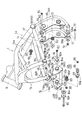
以下、本発明の好ましい実施形態について図面を参照しながら説明する。この明細書中の左右方向は、自動二輪車に乗車したライダーから見た左右を言う。図1において、本発明の自動二輪車は、車体フレームFRの前半部を構成するメインフレーム1の前端にフロントフォーク2が支持され、このフロントフォーク2の下端部に前輪4が支持されている。フロントフォーク2は、これを支持するアッパブラケット6およびロワブラケット7とともに、メインフレーム1の前端のヘッドパイプ8に回動自在に支持されており、アッパブラケット6にハンドル10が取り付けられている。
Hereinafter, preferred embodiments of the present invention will be described with reference to the drawings. The left and right directions in this specification refer to the left and right as viewed from a rider riding a motorcycle. In FIG. 1, in the motorcycle according to the present invention, a front fork 2 is supported at a front end of a
一方、メインフレーム1の後端下部には、スイングアームブラケット11が固着され、このスイングアームブラケット11に、図示しない後輪を支持するスイングアームが揺動自在に軸支されている。メインフレーム1の中央下部には後輪を駆動する原動機であるエンジンEが支持されている。エンジンEは、クランク軸20を支持するクランクケース22と、その上部に連結されたシリンダブロック24とを有している。シリンダブロック24は、ピストン(図示せず)を内蔵したシリンダ26と、その上方のシリンダヘッド28とを有している。
On the other hand, a
メインフレーム1の後部には、車体フレームFRの後半部を形成するリヤフレーム12が連結されており、このリヤフレーム12の上部を形成するシートレール12aに、ライダーシート13とその後方の同乗者シート(図示せず)とが支持されている。メインフレーム1の上部、つまり車体上部にはヘッドパイプ8とライダーシート13との間に位置して、燃料タンク18が支持されている。
A
前記メインフレーム1は、ヘッドパイプ8から概ね後方斜め下方に延びており、図2に示すように、エンジンEの上方から後方にかけて延びたのち屈曲して下方に延びる左右一対の第1フレーム片1aと、第1フレーム片1aの前部から下方斜め後方に延びる左右一対の第2フレーム片1bと、第2フレーム片1bの下端からシリンダブロック24の外側方を通って後方に延びる左右一対の第3フレーム片1cとを有している。
The
第1フレーム片1aは、エンジンEの上方から後方にかけて延びる第1フレーム片前半部1aaと、第1フレーム片前半部1aaの後端に連結されて下方に延びる第1フレーム片後半部1abとからなる。前記スイングアームブラケット11は、第3フレーム片1cと第1フレーム片後半部1abとの連結部を挟んだ部分に溶接で固着されている。第3フレーム片1cの前端は、接続部36を介して第2フレーム片1bの下端に連結され、第3フレーム片1cの後端は、第1フレーム片1aにおける第1フレーム片前半部1aaと第1フレーム片後半部1abとの連結部に連結されている。
The
第1フレーム片1aの第1フレーム片前半部1aaと第2フレーム片1bとの間に第4フレーム片1dが架け渡されている。第1フレーム片1aの中間部、詳細には、第1フレーム片1aにおける第3フレーム片1cの後端が連結される部分が、左右方向に延びる第1クロスパイプ37により連結されている。左右のスイングアームブラケット11,11の上部は、第2クロスパイプ39により連結されている。第1フレーム片1aの下端は、第3クロスパイプ41により連結されている。これら第1〜3フレーム片1a,1b,1c、第4フレーム片1dおよび第1〜3クロスパイプ37,39,41は溶接により連結されている。
A
メインフレーム1の右側の接続部36Rに、板材からなる第1取付片46が溶接により固着され、第1取付片46に2つのねじ孔46aが形成されている。本実施形態では、ねじ孔46aは溶接ナットにより形成されている。左側の接続部36Lは、有底の円筒パイプ48からなり、円筒パイプ48の底部にボルト挿通孔48aが形成されている。左側の第2フレーム片1bにおける接続部36Lの近傍に、板材からなる第2取付片50が溶接により固着され、第2取付片50に1つのボルト挿通孔50aが形成されている。
A
図1のエンジンEは、その前部、後方上部および後方下部の3箇所でメインフレーム1に支持されている。具体的には、メインフレーム1に、エンジンEの前部を支持する第1マウント部M1、エンジンEの後方上部を支持する第2マウント部M2およびエンジンEの後方下部を支持する第3マウント部M3が形成されている。第1および第2マウント部M1,M2は、防振用の後述する図2の第1ダンパ69および第2ダンパ60をそれぞれ有している。図1の車体フレームFRは、エンジンE下方のダウンチューブを省略し、エンジンEをフレーム強度の一部に取り入れた構造である。
The engine E in FIG. 1 is supported by the
第1マウント部M1は、第2フレーム片1bと第3フレーム片1cとの接続部36に設けられた左右一対の支持部38,38で構成されている。詳細には、接続部36に左右一対のエンジンブラケット40が連結され、このエンジンブラケット40に第1マウント部M1の支持部38が形成されている。つまり、支持部38は接続部36よりも下方に位置している。この第1マウント部M1に、シリンダ26が支持されている。
The first mount portion M1 includes a pair of left and
各エンジンブラケット40,40は金属製の板材からなり、その中心部に形成された貫通孔40aに、円筒状の金属パイプ38が挿入されて溶接で固定されている。この金属パイプ38が前記支持部38を構成する。左右のエンジンブラケット40,40は、左右方向に延びる連結部材44により連結されている。連結部材44は金属製のパイプからなり、その左右方向両端が溶接により左右のエンジンブラケット40,40の内側面に固着されている。連結部材44は、支持部38の下方に位置している。
Each of the
右側のエンジンブラケット40Rの上部に、2つのボルト挿通孔42が形成されている。ボルト挿通孔42は、第1取付片46のねじ孔46aに相当する位置に形成されている。左側のエンジンブラケット40Lの上部に、2つのねじ孔52が形成されている。本実施形態では、ねじ孔52は溶接ナット(図示せず)により形成されている。ねじ孔52は、第2取付片50のボルト挿通孔50aと円筒パイプ48の底壁に設けたボルト挿通孔48aに相当する位置に形成されている。
Two bolt insertion holes 42 are formed in the upper portion of the
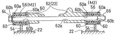
第2マウント部M2は、スイングアームブラケット11に設けられている。詳細には、第2クロスパイプ39に、第3取付片54を介して円筒パイプ56が連結されており、この円筒パイプ56が第2マウント部M2を構成している。円筒パイプ56は、左右方向を向いた軸心を有し、左右方向に並んで2つ設けられている。第2マウント部M2にクランクケース22(図1)の後方上部が支持されている。
The second mount portion M2 is provided on the
第3マウント部M3は、第1フレーム片1aの下端に設けられている。詳細には、第3クロスパイプ41に、板材からなるマウント金具58が前方に突出するように連結されており、このマウント金具58が第3マウント部M3を構成している。マウント金具58は、左右方向を向いたボルト挿通孔58aを有し、左右方向に並んで2つ設けられている。第3マウント部M3にクランクケース22(図1)の後方下部が支持されている。
The third mount M3 is provided at the lower end of the
エンジンの取付手順を説明する。まず、第2マウント部M2の円筒パイプ56に、ゴムのような弾性部材からなる4つの第2ダンパ60を挿入する。第2ダンパ60は、片側に鍔部60aを有する円筒状で、左右逆方向から1つの円筒パイプ56に対して2つ挿入される。図4に示すように、第2ダンパ60の鍔部60aは、円筒パイプ56の端面に当接あるいは対向する。
The engine installation procedure will be described. First, four
つぎに、2つの円筒パイプ56の間に位置するクランクケース22の後方上部の第2被支持部62に、車体左側からボルト64を各第2ダンパ60の内部60bおよび第2被支持部62のボルト挿通孔62aに挿通し、ナット66で締め付ける。これにより、第2マウント部M2にクランクケース22の後方上部が支持される。
Next,
さらに、図5に示すように、第3マウント部M3の2つのマウント金具58の間に、クランクケース22の後方下部の第3被支持部68を配置した状態で、車体左側からボルト70を各マウント金具58のボルト挿通孔58aおよび第3被支持部68のボルト挿通孔68aに挿通し、ナット72で締め付ける。これにより、第3マウント部M3にクランクケース22の後方下部が支持される。
Further, as shown in FIG. 5, with the third supported
つづいて、図2の第1マウント部M1の左右の支持部38に、ゴムのような弾性部材からなる概ね円筒状の第1ダンパ69を車体内側から挿入する。図3に示すように、第1ダンパ69は、車体内側の大径のフランジ部69aと、フランジ部69aに連なり支持部38の内部にある中間部69bと、車体外側の小径の凸部69cとからなる。中間部69bの外径は支持部38の内径と同じである。フランジ部69aの外径は支持部38の内径よりも大きく、フランジ部69aは支持部38の端面38aに当接している。中間部69bは、図2に示すように、円筒体の外周に軸方向に平行に延びる複数の突起が形成されている。
Subsequently, a substantially cylindrical
つぎに、ボルト74,76によりエンジンブラケット40をメインフレーム1に取り付ける。詳細には、ボルト74を右側のエンジンブラケット40Rのボルト挿通孔42に挿通し、第1取付片46のねじ孔46aに締め付ける。また、ボルト76を円筒パイプ48のボルト挿通孔48aおよび第2取付片50のボルト挿通孔50aに挿通し、左側のエンジンブラケット40Lのねじ孔52に締め付ける。
Next, the
つづいて、図3に示すように、2つの支持部38の間に、シリンダ26に一体形成された左右の第1被支持部78L,78Rを位置させた状態で、ゴムのような弾性体からなる円環状の弾性ワッシャ84を第1ダンパ69の凸部69cの外周に装着し、さらに弾性ワッシャ84に円環椀状のキャップ82を被せる。その後、車体左側からボルト80を椀状のキャップ82の中心孔82a、第1ダンパ69の中心孔69dおよび左側の第1被支持部78Lのボルト挿通孔78Laの順に挿通し、ナット86で締め付ける。これにより、左側の第1マウント部M1にシリンダ26の前部が支持される。
Next, as shown in FIG. 3, the left and right first supported
さらに、右側の第1マウント部M1では、右側の第1被支持部78Rと第1ダンパ69との間に両端鍔付円筒状のカラー88を介在させた状態で、車体右側からボルト80をキャップ82の中心孔82a、第1ダンパ69の中心孔69d、カラー88の中心孔88aおよび右側の第1被支持部78Rのボルト挿通孔78Raの順に挿通し、ナット86で締め付ける。これにより、右側の第1マウント部M1にシリンダ26の前部が支持される。最後に、各ボルト64,70,74,76,80を規定のトルクにて締め付ける。以上により、図1のエンジンEがメインフレーム1に取り付けられる。
Further, in the first mount portion M1 on the right side, the
図3に示すように、第1マウント部M1は、左右一対の支持部38,38とシリンダ26に設けられた左右一対の被支持部78L,78Rとが第1ダンパ69を介して連結されたラバーマウントで構成されている。
As shown in FIG. 3, the first mount portion M <b> 1 has a pair of left and
図4に示すように、第2マウント部M2は、左右一対の円筒パイプ56,56とクランクケース22に設けられた左右一対の第2被支持部62,62との間に、第2ダンパ60が介在されたラバーマウントで構成されている。
As shown in FIG. 4, the second mount portion M <b> 2 includes a
図5に示すように、第3マウント部M3は、マウント金具58とクランクケース22に設けられた被支持部68との間に、弾性部材が介在しないリジッドマウントで構成されている。
As shown in FIG. 5, the third mount portion M <b> 3 is configured by a rigid mount in which no elastic member is interposed between the mount fitting 58 and the supported
上記構成によれば、図1のエンジンEの前部を支持する第1マウント部M1がラバーマウントで構成されているので、エンジンEの振動がメインフレーム1に伝わるのを防ぐことができる。特に、第1マウント部M1はハンドル10に近いので、第1マウント部M1をラバーマウントとすることで、メインフレーム1からハンドル10を介してライダーの腕に振動が伝わるのが抑制され、乗り心地がよくなる。しかも、図2の連結部材44により左右の接続部36,36が連結されているので、ラバーマウントを使用しているにもかかわらず、十分なフレーム強度を確保できる。
According to the above configuration, since the first mount portion M1 that supports the front portion of the engine E in FIG. 1 is configured by the rubber mount, it is possible to prevent the vibration of the engine E from being transmitted to the
また、図1のシリンダヘッド28よりも低温のシリンダ26が、第1マウント部M1によりメインフレーム1に支持されているので、メインフレーム1の強度を確保しやすい。
Further, since the
さらに、ライダーシート13に近い第2マウント部M2もラバーマウントで構成されているので、エンジンEの振動がライダーシート13を介してライダーに伝わるのを防ぐことができ、その結果、乗り心地がよくなる。
Further, since the second mount portion M2 close to the
出力スプロケット90に近い第3マウント部M3は、弾性部材が介在しないリジッドマウントで構成されているので、出力スプロケット90の揺れを防ぐことができ、その結果、出力スプロケット90に連結されるチェーン、ベルト等(図示せず)の動作が安定する。
Since the third mount portion M3 close to the
また、接続部36にエンジンブラケット40が連結され、第1マウント部M1を構成する支持部38が、エンジンブラケット40における接続部36よりも下方に位置している。これにより、第2フレーム片1bを下方に大きく延ばすことなく、シリンダヘッド28よりも低温のシリンダ26の前部を支持できる。
Further, the
さらに、第2マウント部M2が、強度の高いスイングアームブラケット11に設けられているので、エンジンEを安定して支持できる。
Furthermore, since the second mount portion M2 is provided on the
本発明は、以上の実施形態に限定されるものでなく、本発明の要旨を逸脱しない範囲内で、種々の追加、変更または削除が可能である。例えば、上記実施形態では、第1および第2マウント部M1,M2をラバーマウントで構成したが、少なくとも第1マウント部M1がラバーマウントであればよく、第2および第3はマウント部M2,M3は、ラバーマウントであってもリジッドマウントのどちらでもよい。また、第1マウント部M1でクランクケース22の前部を支持してもよい。さらに、第3マウント部M3もスイングアームブラケット11に設けてもよい。したがって、そのようなものも本発明の範囲内に含まれる。
The present invention is not limited to the above-described embodiment, and various additions, modifications, or deletions can be made without departing from the gist of the present invention. For example, in the above embodiment, the first and second mount portions M1, M2 are configured by rubber mounts, but at least the first mount portion M1 may be a rubber mount, and the second and third mount portions M2, M3 Either a rubber mount or a rigid mount may be used. Further, the front portion of the
1 メインフレーム
1a 第1フレーム片
1b 第2フレーム片
1c 第3フレーム片
8 ヘッドパイプ
11 スイングアームブラケット
22 クランクケース
24 シリンダブロック
36 接続部
38 支持部
40 エンジンブラケット
44 連結部材
69 第1ダンパ(弾性部材)
78L,78R 第1被支持部
E エンジン
FR 車体フレーム
M1 第1マウント部
M2 第2マウント部
M3 第3マウント部
DESCRIPTION OF
78L, 78R First supported portion E Engine FR Body frame M1 First mount portion M2 Second mount portion M3 Third mount portion
Claims (5)
前記車体フレームは、ヘッドパイプから後方斜め下方に延びるメインフレームを有し、
前記エンジンは、クランク軸を支持するクランクケースと、その上部に連結されたシリンダブロックとを有し、かつ、エンジンの前部、後方上部および後方下部の3箇所で前記メインフレームに支持され、
前記メインフレームは、前記エンジンの上方から後方にかけて延びる左右一対の第1フレーム片と、前記第1フレーム片の前部から下方斜め後方に延びる左右一対の第2フレーム片と、前記第2フレーム片の下端から前記シリンダブロックの外側方を通って後方に延びて前記第1フレーム片の中間部に連結された左右一対の第3フレーム片とを有し、
前記エンジンの前部を支持する第1マウント部は、前記第2フレーム片と第3フレーム片との接続部に設けられた左右一対の支持部と前記エンジンに設けられた左右一対の被支持部とが弾性部材を介して連結されたラバーマウントで構成され、
前記左右一対の支持部が左右方向に延びる連結部材により連結されて、
前記接続部にブラケットが連結され、
前記第1マウント部の支持部が、前記ブラケットにおける前記接続部よりも下方に位置し、
左右一対の前記ブラケットが前記連結部材により連結されているエンジンのマウント構造。 An engine mounting structure for supporting an engine on a body frame of a motorcycle,
The vehicle body frame has a main frame extending obliquely downward and rearward from the head pipe,
The engine has a crankcase that supports a crankshaft and a cylinder block connected to the crankcase, and is supported by the main frame at three locations, a front part, a rear upper part, and a rear lower part of the engine,
The main frame includes a pair of left and right first frame pieces extending from the upper side to the rear side of the engine, a pair of left and right second frame pieces extending obliquely rearwardly downward from a front portion of the first frame piece, and the second frame piece. A pair of left and right third frame pieces extending rearward from the lower end of the cylinder block through the outside of the cylinder block and connected to an intermediate portion of the first frame piece,
The first mount portion that supports the front portion of the engine includes a pair of left and right support portions provided at a connection portion between the second frame piece and the third frame piece, and a pair of left and right support portions provided in the engine. And a rubber mount connected via an elastic member,
The pair of left and right support portions are connected by a connecting member extending in the left-right direction,
A bracket is coupled to the connection part,
The support portion of the first mount portion is located below the connection portion in the bracket,
An engine mounting structure in which a pair of left and right brackets are connected by the connecting member .
前記シリンダが、前記第1マウント部により前記メインフレームに支持されているエンジンのマウント構造。 The engine mount structure according to claim 1, wherein the cylinder block includes a cylinder having a built-in piston, and a cylinder head above the cylinder.
An engine mount structure in which the cylinder is supported by the main frame by the first mount portion.
Priority Applications (4)
| Application Number | Priority Date | Filing Date | Title |
|---|---|---|---|
| JP2014056086A JP6316042B2 (en) | 2014-03-19 | 2014-03-19 | Engine mounting structure |
| EP15764534.2A EP3121106B1 (en) | 2014-03-19 | 2015-02-04 | Engine mount structure |
| PCT/JP2015/053051 WO2015141310A1 (en) | 2014-03-19 | 2015-02-04 | Engine mount structure |
| US15/244,324 US10059183B2 (en) | 2014-03-19 | 2016-08-23 | Engine mount structure |
Applications Claiming Priority (1)
| Application Number | Priority Date | Filing Date | Title |
|---|---|---|---|
| JP2014056086A JP6316042B2 (en) | 2014-03-19 | 2014-03-19 | Engine mounting structure |
Publications (3)
| Publication Number | Publication Date |
|---|---|
| JP2015178303A JP2015178303A (en) | 2015-10-08 |
| JP2015178303A5 JP2015178303A5 (en) | 2017-03-02 |
| JP6316042B2 true JP6316042B2 (en) | 2018-04-25 |
Family
ID=54144290
Family Applications (1)
| Application Number | Title | Priority Date | Filing Date |
|---|---|---|---|
| JP2014056086A Active JP6316042B2 (en) | 2014-03-19 | 2014-03-19 | Engine mounting structure |
Country Status (4)
| Country | Link |
|---|---|
| US (1) | US10059183B2 (en) |
| EP (1) | EP3121106B1 (en) |
| JP (1) | JP6316042B2 (en) |
| WO (1) | WO2015141310A1 (en) |
Families Citing this family (4)
| Publication number | Priority date | Publication date | Assignee | Title |
|---|---|---|---|---|
| US9469363B1 (en) * | 2013-03-15 | 2016-10-18 | John M. Speicher | High performance motorcycle |
| JP2018203038A (en) * | 2017-06-02 | 2018-12-27 | ヤマハ発動機株式会社 | Saddle-riding type vehicle |
| JP6489172B2 (en) * | 2017-08-03 | 2019-03-27 | マツダ株式会社 | Sound vibration attenuation structure of vehicle |
| JP6671403B2 (en) * | 2018-02-28 | 2020-03-25 | 本田技研工業株式会社 | Engine hanger structure |
Family Cites Families (11)
| Publication number | Priority date | Publication date | Assignee | Title |
|---|---|---|---|---|
| JPS494428Y1 (en) * | 1970-07-02 | 1974-02-01 | ||
| FR2401459A1 (en) | 1977-08-26 | 1979-03-23 | Cii Honeywell Bull | PORTABLE INFORMATION MEDIA EQUIPPED WITH A MICROPROCESSOR AND A PROGRAMMABLE DEAD MEMORY |
| JPS5446447U (en) * | 1977-09-06 | 1979-03-30 | ||
| JPH0550969A (en) * | 1991-08-15 | 1993-03-02 | Suzuki Motor Corp | Engine mounting device for motor scooter |
| JPH0616171A (en) | 1991-11-01 | 1994-01-25 | Yamaha Motor Co Ltd | Engine support structure of motorcycle |
| JP4105442B2 (en) * | 2002-01-31 | 2008-06-25 | 本田技研工業株式会社 | Engine mount structure for motorcycles |
| JP4708061B2 (en) * | 2005-03-31 | 2011-06-22 | 本田技研工業株式会社 | Body frame structure |
| US7644795B2 (en) * | 2005-06-17 | 2010-01-12 | Kawasaki Jukogyo Kabushiki Kaisha | Vehicle body structure of motorcycle |
| JP4786947B2 (en) * | 2005-06-17 | 2011-10-05 | 川崎重工業株式会社 | Motorcycle body structure |
| JP5814781B2 (en) * | 2011-12-27 | 2015-11-17 | 川崎重工業株式会社 | Power unit mounting structure for motorcycles |
| JP6083134B2 (en) * | 2012-06-08 | 2017-02-22 | スズキ株式会社 | Welded joint structure |
-
2014
- 2014-03-19 JP JP2014056086A patent/JP6316042B2/en active Active
-
2015
- 2015-02-04 WO PCT/JP2015/053051 patent/WO2015141310A1/en active Application Filing
- 2015-02-04 EP EP15764534.2A patent/EP3121106B1/en active Active
-
2016
- 2016-08-23 US US15/244,324 patent/US10059183B2/en active Active
Also Published As
| Publication number | Publication date |
|---|---|
| EP3121106A4 (en) | 2017-11-15 |
| US20160355080A1 (en) | 2016-12-08 |
| WO2015141310A1 (en) | 2015-09-24 |
| EP3121106A1 (en) | 2017-01-25 |
| US10059183B2 (en) | 2018-08-28 |
| JP2015178303A (en) | 2015-10-08 |
| EP3121106B1 (en) | 2019-03-06 |
Similar Documents
| Publication | Publication Date | Title |
|---|---|---|
| JP6316042B2 (en) | Engine mounting structure | |
| JP2007230538A (en) | Suspension structure | |
| US10829178B2 (en) | Vehicle body frame of straddle-type vehicle | |
| JP4607745B2 (en) | Engine support structure for motorcycles | |
| JP6309410B2 (en) | Engine support structure for saddle-ride type vehicles | |
| US20090247309A1 (en) | Shaft drive device | |
| JP4814739B2 (en) | Motorcycle | |
| JP2018203038A (en) | Saddle-riding type vehicle | |
| JP2012236467A (en) | Motorcycle | |
| JP4995060B2 (en) | Motorcycle exhaust system | |
| JP6231270B2 (en) | Saddle type vehicle fuel tank mounting structure | |
| JP6282497B2 (en) | Handle mount structure for saddle riding type vehicles | |
| JP5570376B2 (en) | Step-stay structure for saddle-ride type vehicles | |
| JP4014603B2 (en) | Motor unit support structure for scooter type motorcycles | |
| JP4881685B2 (en) | Motorcycle | |
| JP2016203827A (en) | vehicle | |
| KR101034019B1 (en) | Dynamic damping apparatus | |
| JP6907533B2 (en) | Anti-vibration structure | |
| JP2006027466A (en) | Engine suspension device of saddle riding type vehicle | |
| JP2009161018A (en) | Saddle-riding type vehicle | |
| JP6134243B2 (en) | Suspension structure for saddle riding type vehicles | |
| JP2017197068A (en) | Saddle-riding type vehicle | |
| JP4766901B2 (en) | Motorcycle | |
| JP2020050069A (en) | Saddle-riding vehicle | |
| JP2007091163A (en) | Frame vibration-proofing structure for saddle-riding type vehicle |
Legal Events
| Date | Code | Title | Description |
|---|---|---|---|
| A521 | Request for written amendment filed |
Free format text: JAPANESE INTERMEDIATE CODE: A523 Effective date: 20170124 |
|
| A621 | Written request for application examination |
Free format text: JAPANESE INTERMEDIATE CODE: A621 Effective date: 20170124 |
|
| A131 | Notification of reasons for refusal |
Free format text: JAPANESE INTERMEDIATE CODE: A131 Effective date: 20170829 |
|
| A521 | Request for written amendment filed |
Free format text: JAPANESE INTERMEDIATE CODE: A523 Effective date: 20171004 |
|
| TRDD | Decision of grant or rejection written | ||
| A01 | Written decision to grant a patent or to grant a registration (utility model) |
Free format text: JAPANESE INTERMEDIATE CODE: A01 Effective date: 20180306 |
|
| A61 | First payment of annual fees (during grant procedure) |
Free format text: JAPANESE INTERMEDIATE CODE: A61 Effective date: 20180327 |
|
| R150 | Certificate of patent or registration of utility model |
Ref document number: 6316042 Country of ref document: JP Free format text: JAPANESE INTERMEDIATE CODE: R150 |
|
| S111 | Request for change of ownership or part of ownership |
Free format text: JAPANESE INTERMEDIATE CODE: R313111 |
|
| R350 | Written notification of registration of transfer |
Free format text: JAPANESE INTERMEDIATE CODE: R350 |
|
| R250 | Receipt of annual fees |
Free format text: JAPANESE INTERMEDIATE CODE: R250 |