JP6310331B2 - Data collection apparatus and data collection method for vehicle diagnosis - Google Patents
Data collection apparatus and data collection method for vehicle diagnosis Download PDFInfo
- Publication number
- JP6310331B2 JP6310331B2 JP2014114864A JP2014114864A JP6310331B2 JP 6310331 B2 JP6310331 B2 JP 6310331B2 JP 2014114864 A JP2014114864 A JP 2014114864A JP 2014114864 A JP2014114864 A JP 2014114864A JP 6310331 B2 JP6310331 B2 JP 6310331B2
- Authority
- JP
- Japan
- Prior art keywords
- data
- ecu
- vehicle
- data collection
- collection device
- Prior art date
- Legal status (The legal status is an assumption and is not a legal conclusion. Google has not performed a legal analysis and makes no representation as to the accuracy of the status listed.)
- Active
Links
Images


Description
本発明は、車両診断用のデータ収集装置及びデータ収集方法に関する。 The present invention relates to a data collection device and a data collection method for vehicle diagnosis.
車両の運転中に異常な症状が発生した場合、インスツルメントパネルに設けられた警告灯を点灯する等の警告によって運転者に知らせることが行われている。異常な症状又はこれに伴う警告に伴ってユーザが販売店又は整備工場に車両を持ち込むと、そこで車両の診断又は修理が行われる。 When an abnormal symptom occurs during driving of a vehicle, the driver is informed by a warning such as turning on a warning light provided on the instrument panel. When a user brings a vehicle to a dealer or a maintenance shop with an abnormal symptom or a warning associated therewith, the vehicle is diagnosed or repaired there.
修理を担当する作業者(テクニシャン等)は、故障車両の電子制御装置(以下「ECU」という。)に故障診断機を接続してECUに記憶された故障発生時の故障コード等の情報を読み出すことにより、比較的容易に異常系統(異常が発生している電気回路)を特定することが可能である。この種の故障診断機は広く普及しており、例えば、特許文献1に記載されている。
An operator (technician or the like) in charge of repair connects a fault diagnosis machine to an electronic control device (hereinafter referred to as “ECU”) of a faulty vehicle and reads information such as a fault code at the time of fault stored in the ECU. Thus, it is possible to identify an abnormal system (an electric circuit in which an abnormality has occurred) relatively easily. This type of failure diagnosis machine is widely used, and is described in
ところが、ユーザから異常な症状の訴えは何度もあるものの、故障コードの記録がなく、また、修理担当のテクニシャンが訴えに応じて再現を試みても再現せず、修理が難しい場合(いわゆる難問修理の場合)がある。 However, although there are many complaints of abnormal symptoms from the user, there is no record of the fault code, and even if the technician in charge of repair does not reproduce it even if it tries to reproduce according to the complaint, repair is difficult (so-called difficult problem In case of repair).
このような難問修理に対しては、例えば、特許文献2及び特許文献3に記載されるような大容量の記憶装置を対象車両のECUに一時的に取り付け、数日間に亘ってユーザに運転してもらう。そして、故障診断に必要なデータ(運転パラメータデータ)を記憶装置に収集し、収集したデータを故障診断機又は故障解析装置で検討することにより、詳細な診断を行う。
For such difficult problem repair, for example, a large-capacity storage device as described in Patent Document 2 and
特許文献2では、データの収集や出力を自動で行うため、イグニションキースイッチ51のオンオフ操作及びパソコン接続によるUSB電源のオンオフ操作を検知してデータの収集や出力を行う(要約)。特許文献2では、どの制御データを選択して収集するかは、設定手段である設定部18によって予めデータ収集部15に設定されている。設定部18は、入力操作部を有し、また、設定部18での設定作業のために、予め機種テーブル19が用意されている。そして、作業者が設定部18の入力操作部から車両データ収集装置1の搭載車種を入力すると、機種テーブル19に予めグループ化して格納されている収集すべき制御データの種類(パラメータID)等が、設定部18に読み出され、データ収集部15に設定される([0034])。
In Patent Document 2, since data is collected and output automatically, on / off operation of the ignition key switch 51 and on / off operation of the USB power supply by connecting to a personal computer are detected to collect and output data (summary). In Patent Document 2, which control data is selected and collected is set in the
特許文献3では、作業者がデータ収集条件を入力する([0052])。ここでのデータ収集条件には、車種、型式、仕向地、仕様、ネットワークの種類、データ収集装置18で使用する入力チャンネルの番号、対象となるネットワーク24のボーレートが含まれ得る([0057])。さらに、データ収集条件には、運転パラメータデータDの内容(項目)、データDを要求するECU20(対象ECU20tar)、データDの連続的な取得を行う時間(連続的データ取得時間)、データDの連続的な取得を行う周期(連続的データ取得周期)、データDの収集にかける総時間(データ収集総時間)が含まれ得る([0058])。
In
上記のように、特許文献2、3では、収集する運転パラメータデータの種類等を作業者が設定する必要がある。このため、そのような設定作業に多大な工数がかかるおそれがあると共に、人為的なミスにより誤った設定内容となることも懸念される。
As described above, in
本発明は、上記のような事情を考慮したものであり、データ収集設定にかかる工数の削減及び誤ったデータ収集設定の防止の少なくとも一方が可能な車両診断用のデータ収集装置及びデータ収集方法を提供することを目的する。 The present invention takes the above-described circumstances into consideration, and provides a vehicle diagnostic data collection device and data collection method capable of at least one of reducing man-hours for data collection settings and preventing erroneous data collection settings. The purpose is to provide.
本発明に係る車両診断用のデータ収集装置は、複数のECUを有する車内ネットワークに外部から着脱自在に接続された状態において、車両の各部の動作状態を示す運転パラメータデータを要求するデータ要求信号を、前記複数のECUの少なくとも1つである対象ECUに対して送信し、前記データ要求信号に対応する前記運転パラメータデータを受信してデータ記憶部に記憶するものであって、
前記データ収集装置は、
作業者からの入力に基づいて前記対象ECUの種類を設定する種類設定部と、
前記複数のECUそれぞれが出力可能な前記運転パラメータデータの項目を、前記複数のECUの識別情報に対応させて記憶するデータ項目記憶部と、
前記種類設定部で設定した前記対象ECUの種類毎に搭載ECUの識別情報を前記車両に問い合わせて、前記識別情報を受信した前記搭載ECUを前記対象ECUとして識別し、前記対象ECUとして識別された前記搭載ECUが出力可能な前記運転パラメータデータの項目を、前記搭載ECUの前記識別情報に基づいて前記データ項目記憶部から読み出して収集項目として設定する収集項目設定部と、前記収集項目に対応する前記運転パラメータデータを要求する前記データ要求信号を前記対象ECUに対して送信し、前記データ要求信号に対応する前記運転パラメータデータを受信して前記データ記憶部に記憶させるデータ収集管理部と
を備えることを特徴とする。
A data collection device for vehicle diagnosis according to the present invention provides a data request signal for requesting operation parameter data indicating an operation state of each part of a vehicle in a state in which the vehicle collection network having a plurality of ECUs is detachably connected from the outside. Transmitting to the target ECU that is at least one of the plurality of ECUs, receiving the operation parameter data corresponding to the data request signal, and storing the data in a data storage unit;
The data collection device includes:
A type setting unit for setting the type of the target ECU based on an input from an operator ;
A data item storage unit that stores items of the operation parameter data that can be output by each of the plurality of ECUs in association with identification information of the plurality of ECUs;
Query the identity of the mounted ECU on the vehicle for each type of the target ECU set by the type setting unit identifies the mounted ECU that has received the identification information as the target ECU, it is identified as the target ECU an item of the operating parameter data the mounting ECU can output, a collection item setting unit that sets as a collection item is read from the data item storage unit based on the identification information of the mounted ECU, corresponding to the collection item A data collection management unit that transmits the data request signal for requesting the operation parameter data to the target ECU, receives the operation parameter data corresponding to the data request signal, and stores the data in the data storage unit. It is characterized by that.
本発明によれば、収集項目の設定の少なくとも一部をデータ収集装置が行うため、収集項目の設定に伴う作業者の工数を削減することが可能となる。また、車両から通知された搭載ECUを対象ECUとして識別すると共に、当該対象ECUに対応する項目を収集項目として設定するため、収集項目の設定に伴う作業者の人為的なミスを防止することが可能となる。 According to the present invention, since the data collection device performs at least a part of the setting of the collection item, it is possible to reduce the man-hours of the worker accompanying the setting of the collection item. In addition, since the mounted ECU notified from the vehicle is identified as the target ECU and the item corresponding to the target ECU is set as the collection item, it is possible to prevent an operator's human error due to the setting of the collection item. It becomes possible.
本発明に係る車両診断用のデータ収集装置は、複数のECUを有する車内ネットワークに外部から着脱自在に接続された状態において、車両の各部の動作状態を示す運転パラメータデータを要求するデータ要求信号を、前記複数のECUの少なくとも1つである対象ECUに対して送信し、前記データ要求信号に対応する前記運転パラメータデータを受信してデータ記憶部に記憶するものであって、
前記データ収集装置は、
前記対象ECUの種類を設定する種類設定部と、
前記複数のECUそれぞれが出力可能な前記運転パラメータデータの項目を、前記複数のECUの識別情報に対応させて記憶するデータ項目記憶部と、
前記種類設定部で設定した前記対象ECUの種類毎に搭載ECUの有無を前記車両に問い合わせて前記搭載ECUを前記対象ECUとして識別し、前記対象ECUとして識別された前記搭載ECUが出力可能な前記運転パラメータデータの項目を、前記搭載ECUの識別情報に基づいて前記データ項目記憶部から読み出して収集項目として設定する収集項目設定部と、前記収集項目に対応する前記運転パラメータデータを要求する前記データ要求信号を前記対象ECUに対して送信し、前記データ要求信号に対応する前記運転パラメータデータを受信して前記データ記憶部に記憶させるデータ収集管理部と
を備え、
前記収集項目設定部は、前記データ収集装置を前記車両に接続した状態での起動スイッチの初回オン操作に対応して、前記種類設定部で設定した前記対象ECUの種類毎に前記搭載ECUの有無を前記車両に問い合わせて前記収集項目を設定し、
これに続いて、前記データ収集管理部は、前記起動スイッチのオフ操作及びその後の再オン操作が行われたことを条件として、前記データ要求信号の送信及び前記運転パラメータデータの記憶を開始してもよい。
A data collection device for vehicle diagnosis according to the present invention provides a data request signal for requesting operation parameter data indicating an operation state of each part of a vehicle in a state in which the vehicle collection network having a plurality of ECUs is detachably connected from the outside. Transmitting to the target ECU that is at least one of the plurality of ECUs, receiving the operation parameter data corresponding to the data request signal, and storing the data in a data storage unit;
The data collection device includes:
A type setting unit for setting the type of the target ECU;
A data item storage unit that stores items of the operation parameter data that can be output by each of the plurality of ECUs in association with identification information of the plurality of ECUs;
For each type of the target ECU set by the type setting unit, the vehicle is inquired about the presence or absence of the mounted ECU, the mounted ECU is identified as the target ECU, and the mounted ECU identified as the target ECU can output the An item of operation parameter data is read from the data item storage unit based on identification information of the mounted ECU and set as a collection item, and the data requesting the operation parameter data corresponding to the collection item A data collection management unit for transmitting a request signal to the target ECU, receiving the operation parameter data corresponding to the data request signal, and storing the operation parameter data in the data storage unit;
With
The collection item setting unit is provided with the presence or absence of the on-board ECU for each type of the target ECU set by the type setting unit in response to an initial ON operation of a start switch in a state where the data collection device is connected to the vehicle. To the vehicle to set the collection item,
Subsequently, the data collection management unit starts transmission of the data request signal and storage of the operation parameter data on the condition that the start switch is turned off and then turned on again. Also good.
これにより、収集項目の設定の少なくとも一部及び運転パラメータデータの収集開始は、車内ネットワークに対するデータ収集装置の接続と、起動スイッチの操作とにより行うことができる。従って、作業者は、収集項目の設定の少なくとも一部及び運転パラメータデータの収集開始を簡易な操作で行うことが可能となる。 Thereby, at least a part of the setting of the collection item and the start of collection of the operation parameter data can be performed by connecting the data collection device to the in-vehicle network and operating the start switch. Therefore, the operator can perform at least a part of the collection item setting and the start of operation parameter data collection with a simple operation.
前記車内ネットワークに対する前記データ収集装置の接続が一旦解除された場合には、新たな車内ネットワークに接続後の前記起動スイッチの初回オン操作に対応して、前記種類設定部で設定した前記対象ECUの種類毎に前記搭載ECUの有無を前記新たな車内ネットワークに問い合わせて新たな収集項目を設定してもよい。これにより、データ収集装置をある車両(第1車両)から取り外して他の車両(第2車両)に付け替えることで、診断対象車両を容易に変更することが可能になる。 When the connection of the data collection device to the in-vehicle network is once released, the target ECU of the target ECU set by the type setting unit in response to the first-on operation of the start switch after connecting to the new in-vehicle network. A new collection item may be set by inquiring the new in-vehicle network about the presence or absence of the mounted ECU for each type. Accordingly, the diagnosis target vehicle can be easily changed by removing the data collection device from a certain vehicle (first vehicle) and replacing it with another vehicle (second vehicle).
前記データ収集装置と前記車内ネットワークとの接続は、前記車両のデータリンクコネクタを介して行われ、前記データ収集装置は、前記データリンクコネクタを介した車載電源からの供給電力により起動してもよい。これにより、データ収集装置の起動タイミングを、データリンクコネクタへの接続時とすることができる。従って、診断対象車両の変更のためのデータリンクコネクタへの着脱に伴ってデータ収集装置の再起動を行うことができ、診断対象車両の変更後もデータ収集装置を簡単に作動させることが可能となる。 The connection between the data collection device and the in-vehicle network may be made via a data link connector of the vehicle, and the data collection device may be activated by power supplied from an in-vehicle power source via the data link connector. . Thereby, the starting timing of the data collection device can be set at the time of connection to the data link connector. Accordingly, the data collection device can be restarted with the attachment / detachment of the data link connector for changing the diagnosis target vehicle, and the data collection device can be easily operated even after the change of the diagnosis target vehicle. Become.
前記種類設定部は、複数の車種を統合し且つ各車種に搭載されているECUを機能毎の種類で区分してもよい。これにより、作業者による入力負担の軽減又は入力ミスの防止を図りつつ、データ収集装置における演算負荷及びこれに伴う作業者の工数削減を図ることが可能となる。 The type setting unit may integrate a plurality of vehicle types and classify ECUs mounted on each vehicle type according to type for each function. As a result, it is possible to reduce the calculation load in the data collection device and the number of man-hours associated with the operator while reducing the input burden on the operator or preventing an input error.
本発明に係る車両診断用のデータ収集方法は、複数のECUを有する車内ネットワークに外部から着脱自在に接続された状態において、車両の各部の動作状態を示す運転パラメータデータを要求するデータ要求信号を、前記複数のECUの少なくとも1つである対象ECUに対して送信し、前記データ要求信号に対応する前記運転パラメータデータを受信して記憶部に記憶するデータ収集装置を用いるものであって、
前記データ収集装置は、
作業者からの入力に基づいて前記対象ECUの種類を設定する種類設定処理と、
前記複数のECUそれぞれが出力可能な前記運転パラメータデータの項目を、前記複数のECUの識別情報に対応させて前記記憶部に記憶させる記憶処理と、
前記種類設定処理で設定した前記対象ECUの種類毎に搭載ECUの識別情報を前記車両に問い合わせて、前記識別情報を受信した前記搭載ECUを前記対象ECUとして認識し、前記対象ECUとして識別された前記搭載ECUが出力可能な前記運転パラメータデータの項目を、前記搭載ECUの前記識別情報に基づいて前記記憶部から読み出して収集項目として設定する収集項目設定処理と、
前記収集項目に対応する前記運転パラメータデータを要求する前記データ要求信号を前記対象ECUに対して送信し、前記データ要求信号に対応する前記運転パラメータデータを受信して前記記憶部に記憶させるデータ収集処理と
を含むことを特徴とする。
A data collection method for vehicle diagnosis according to the present invention includes a data request signal for requesting operation parameter data indicating an operation state of each part of a vehicle in a state in which the vehicle is detachably connected to an in-vehicle network having a plurality of ECUs. Using a data collection device that transmits to at least one of the plurality of ECUs, receives the operating parameter data corresponding to the data request signal, and stores it in a storage unit,
The data collection device includes:
A type setting process for setting the type of the target ECU based on an input from an operator ;
A storage process for storing the operation parameter data items that can be output by each of the plurality of ECUs in the storage unit in association with identification information of the plurality of ECUs,
Query the identity of the mounted ECU on the vehicle for each type of the target ECU set by the type setting processing to recognize the mounting ECU that has received the identification information as the target ECU, it is identified as the target ECU a collection item setting process of setting a collection item is read from the storage unit based on the mounting ECU items of the operational parameter data that can be output, the identification information of the mounted ECU,
Data collection for transmitting the data request signal requesting the operation parameter data corresponding to the collection item to the target ECU, receiving the operation parameter data corresponding to the data request signal, and storing the data in the storage unit And processing.
本発明によれば、データ収集設定にかかる工数の削減及び誤ったデータ収集設定の防止の少なくとも一方が可能となる。 According to the present invention, it is possible to reduce the man-hour required for data collection setting and / or to prevent erroneous data collection setting.
A.一実施形態
[1.構成]
(1−1.全体構成)
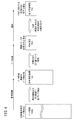
図1は、本発明の一実施形態に係るデータ収集装置18を含む診断システム10(以下「システム10」ともいう。)の概略的な構成を示すブロック図である。システム10は、診断対象としての車両12と、車両12外部から車両12の故障診断を行う外部診断機14と、外部診断機14に車両12の情報を提供するサーバ15とを有する。外部診断機14は、診断機本体16(以下「本体16」ともいう。)及びデータ収集装置18(data logger)を有する。
A. One Embodiment [1. Constitution]
(1-1. Overall configuration)
FIG. 1 is a block diagram showing a schematic configuration of a diagnostic system 10 (hereinafter also referred to as “
(1−2.車両12)
本実施形態の車両12は、駆動用エンジン及び走行モータ(いずれも図示せず)を有するハイブリッド車としての自動四輪車である。或いは、車両12は、走行モータを有さずエンジンのみを有するガソリン車、電気自動車(battery vehicle)、燃料電池車等の車両であってもよく、また、自動二輪車、自動三輪車等の車両であってもよい。
(1-2. Vehicle 12)
The
車両12は、車両12を制御するための複数の電子制御装置20a〜20i(以下「第1〜第9ECU20a〜20i」又は「ECU20a〜20i」といい、「ECU20」と総称する。)と、ゲートウェイ22と、低電圧バッテリ24(以下「バッテリ24」ともいう。)とを有する。なお、図1では、理解を容易化するため、9つのECU20a〜20iのみを示しているが、それ以外のECU20を設けることもできる。ECU20の数としては、例えば、2〜数百個とすることができる。
The
ECU20の例としては、例えば、エンジンECU、モータECU、トランスミッションECU、車両挙動安定ECU(以下「VSA ECU」という。)、アンチロックブレーキシステムECU(以下「ABS ECU」という。)、電動パワーステアリングECU(以下「EPS ECU」という。)、バッテリECU、メータECU、エアコンディショナECU(以下「エアコンECU」という。)、補助拘束システムECU(以下「SRS ECU」という。)、イモビライザECU等を挙げることができる。 Examples of the ECU 20 include an engine ECU, a motor ECU, a transmission ECU, a vehicle behavior stability ECU (hereinafter referred to as “VSA ECU”), an anti-lock brake system ECU (hereinafter referred to as “ABS ECU”), and an electric power steering ECU. (Hereinafter referred to as “EPS ECU”), battery ECU, meter ECU, air conditioner ECU (hereinafter referred to as “air conditioner ECU”), auxiliary restraint system ECU (hereinafter referred to as “SRS ECU”), immobilizer ECU, and the like. Can do.
エンジンECUは、図示しないエンジンの出力を制御する。モータECUは、図示しない走行モータの出力を制御する。トランスミッションECUは、図示しないトランスミッションを制御する。VSA ECUは、車両挙動安定化(Vehicle Stability Assist)制御を実行する。ABS ECUは、アンチロックブレーキ制御を実行する。EPS ECUは、操舵アシスト制御を実行する。バッテリECUは、図示しない高電圧バッテリ又は低電圧バッテリ24の充放電等を制御する。メータECUは、図示しないインストルメントパネルに設けられたメータ表示装置(図示せず)を制御する。エアコンECUは、図示しないエアコンディショナを制御する。SRS ECUは、図示しないエアバッグシステムの制御を行う。イモビライザECUは、図示しないイモビライザ装置及びスマートキーシステムの制御を行う。 The engine ECU controls the output of an engine (not shown). The motor ECU controls the output of a travel motor (not shown). The transmission ECU controls a transmission (not shown). The VSA ECU executes vehicle behavior stability (Vehicle Stability Assist) control. The ABS ECU performs antilock brake control. The EPS ECU executes steering assist control. The battery ECU controls charging / discharging of a high voltage battery or a low voltage battery 24 (not shown). The meter ECU controls a meter display device (not shown) provided on an instrument panel (not shown). The air conditioner ECU controls an air conditioner (not shown). The SRS ECU controls an airbag system (not shown). The immobilizer ECU controls an immobilizer device and a smart key system (not shown).
各ECU20は、入出力部26、演算部28及び記憶部30を有する。なお、図1では、第1ECU20aのみ入出力部26、演算部28及び記憶部30を図示し、その他のECU20b〜20iについては内部構成の図示を省略している。
Each ECU 20 includes an input /
第1〜第6ECU20a〜20fは、通信バス36aを介して接続され、車内ネットワーク34a(以下「ネットワーク34a」ともいう。)を構成する。本実施形態におけるネットワーク34aは、CAN(Controller Area Network)であり、特に、ISO11898で定義されるようないわゆる高速通信CAN(以下「高速CAN」という。)である。第7〜第9ECU20g〜20iは、通信バス36bを介して接続され、車内ネットワーク34b(以下「ネットワーク34b」ともいう。)を構成する。本実施形態におけるネットワーク34bは、CANであり、特に、ISO11519で定義されるようないわゆる低速通信CAN(以下「低速CAN」という。)である。或いは、ネットワーク34a、34bは、LIN(Local Interconnect Network)、FlexRay、Kライン等のその他のネットワークに対して本発明を適用することもできる。以下では、ネットワーク34a、34bを車内ネットワーク34又はネットワーク34と総称する。
The first to
通信バス36aとバッテリ24からの電力線37とは、車室内(例えば、図示しないインスツルメントパネルの一部)に設けられたデータリンクコネクタ38に接続している。
The
なお、図1では、バッテリ24からの電力線37がコネクタ38にのみ接続されているが、バッテリ24は、例えば、12Vバッテリであり、車両12の低電圧系の各構成要素(例えば、ECU20a〜20i)にも電力を供給する。
In FIG. 1, the
また、車両12に搭載されている全てのECU20には、イグニッションスイッチ40(以下「IGSW40」という。)を介して電源が供給されており、且つECU20の中には、IGSW40がオフである場合にもバッテリ24から電力供給を受けて起動を続けるものも存在する場合がある。この場合、IGSW40がオンのときとは違った動作を継続するように設定される。
Further, all ECUs 20 mounted on the
(1−3.外部診断機14)
上記の通り、外部診断機14は、診断機本体16及びデータ収集装置18を有する。
(1-3. External diagnostic machine 14)
As described above, the external
(1−3−1.診断機本体16)
(1−3−1−1.概要)
診断機本体16は、データ収集装置18の各種設定(動作設定等)を行うと共に、データ収集装置18が収集した運転パラメータデータD(以下「データD」ともいう。)を解析して故障診断を行う。故障診断の代わりにその他の診断を行ってもよい(詳細は後述する。)。
(1-3-1. Diagnostic machine body 16)
(1-3-1. Overview)
The
図1に示すように、本体16は、入出力部50、演算部52、記憶部54、表示部56及びコネクタ58を有する。
As shown in FIG. 1, the
本体16は、例えば、市販のノート型パーソナルコンピュータ、タブレット型コンピュータ又はスマートフォンから構成することができる。本体16は、必ずしも単一の筐体から構成される必要はなく、例えば、本体としてのパーソナルコンピュータと、データ収集装置18とのインタフェースとしての子機(中継器)とから構成してもよい。
The
(1−3−1−2.演算部52の各種機能)
図2は、診断機本体16及びデータ収集装置18が有する各種機能を示す図である。図2に示すように、診断機本体16は、収集条件設定機能60と、データ収集装置通信機能62と、データ解析機能64とを有する。各機能60、62、64は、記憶部54に記憶されたプログラムを演算部52が実行すること等により実現される。
(1-3-1-2. Various functions of the calculation unit 52)
FIG. 2 is a diagram illustrating various functions of the
収集条件設定機能60は、データ収集装置18がデータDを収集する条件(例えば、データDの取得対象項目、取得期間等)であるデータ収集条件を設定する。
The collection
データ収集装置通信機能62は、データ収集装置18との間の通信に関連した機能である。通信機能62は、データ収集装置18に対してデータ収集条件を送信する収集条件送信機能66と、データ収集装置18からデータDを読み出す収集データ読出し機能68とを有する。
The data collection
データ解析機能64は、データ収集装置18から取得したデータDを用いて故障診断のためのデータ解析を行う。データ解析機能64は、異常が発生しているECU20(以下「異常ECU20mal」ともいう。)を判定する異常判定部として機能する。また、データ解析機能64は、サーバ15との間で通信し、車両12が搭載しているECU20(以下「搭載ECU20ins」ともいう。)を特定する搭載ECU特定部としても機能する。搭載ECU20insの特定に際しては、車両12の車両識別番号(以下「VIN」という。)を用いる(詳細は、後述する。)。
The
(1−3−1−3.記憶部54)
記憶部54(図1)は、機能60、62、64の実行等のための各種プログラム及び各種データベースを記憶している。当該データベースには、データ項目データベース70(以下「データ項目DB70」又は「DB70」という。)が含まれる。DB70には、データ収集装置18が収集し得るデータDの項目(以下「データ項目Idata」ともいう。)が蓄積されている。DB70は、駆動源に応じた車両12の種類に基づいてデータ項目Idataを区分している。駆動源に応じた車両12の種類としては、例えば、ガソリン車、ディーゼル車、ハイブリッド車、電気自動車等を含めることができる。
(1-3-1-3. Storage Unit 54)
The storage unit 54 (FIG. 1) stores various programs and various databases for executing the
(1−3−2.データ収集装置18)
(1−3−2―1.概要)
データ収集装置18は、車両12における運転パラメータデータDを収集する。図1に示すように、データ収集装置18は、入出力部80、演算部82、記憶部84、表示部86、キャパシタ88、通信線90、電力線92及びコネクタ94を有する。コネクタ94は、例えば、USBコネクタである。
(1-3-2. Data collection device 18)
(1-3-2-1. Overview)
The
(1−3−2―2.演算部82の各種機能)
図2に示すように、データ収集装置18は、本体通信機能100及びデータ収集機能102を有する。各機能100、102は、記憶部84に記憶されたプログラムを演算部82が実行すること等により実現される。本体通信機能100は、診断機本体16との間の通信に関連した機能であり、データ収集機能102は、車両12との間でのデータDの収集に関連した機能である。
(1-3-2-2. Various functions of the calculation unit 82)
As shown in FIG. 2, the
本体通信機能100は、収集条件読込み機能104及び収集データ送信機能106を有する。収集条件読込み機能104は、データ収集装置18がデータDを収集する条件(データ収集条件)を診断機本体16から読み込む機能である。収集データ送信機能106は、データ収集装置18が収集したデータDを診断機本体16に送信する機能である。
The main
データ収集機能102は、要求信号特定機能108、データ要求機能110及びデータ受信・記憶機能112を有する。要求信号特定機能108は、車両12に対してデータDの送信を要求するデータ要求信号Sreqを特定する機能である。データ要求機能110は、データDを要求する対象であるECU20(以下「対象ECU20tar」という。)に対してデータ要求信号Sreqを送信して、特定項目のデータDを要求する機能である。データ受信・記憶機能112は、データ要求信号Sreqに応じて対象ECU20tarが出力したデータDを受信し、記憶部84(データ記憶部)に記憶する機能である。
The
(1−3−2−3.記憶部84)
記憶部84は、機能100、102の実行等のための各種プログラム及び各種データベースを記憶している。当該データベースには、データ項目データベース120(以下「データ項目DB120」、「項目DB120」又は「DB120」という。)が含まれる。本体16のDB70と同様、データ収集装置18のDB120には、データ収集装置18が収集し得る運転パラメータデータDの項目(データ項目Idata)が蓄積されている。但し、DB120に蓄積されるデータ項目Idataは、本体16から受信したもののみである。換言すると、DB120に蓄積されるデータ項目Idataは、DB70に蓄積されるデータ項目Idataの一部である。DB120は、データ項目記憶部として機能する。
(1-3-2-2. Storage unit 84)
The
(1−3−2―4.キャパシタ88)
キャパシタ88は、バッテリ24からの電力により充電され、コネクタ94がコネクタ38から取り外された際にデータ収集装置18内に電力を供給する。
(1-3-4-2. Capacitor 88)
The
なお、図1では、コネクタ94からの電力線92がキャパシタ88にのみ接続されているが、電力線92は、キャパシタ88に加え、その他の部位(例えば、演算部82)にも接続される。このため、バッテリ24又はキャパシタ88からの電力が当該その他の部位にも供給される。
In FIG. 1, the
(1−4.サーバ15)
サーバ15は、外部診断機14からの要求に応じて外部診断機14に対して車両12の各種情報を提供する。サーバ15は、入出力部、演算部、記憶部及び表示部(いずれも図示せず)を備える。図1に示すように、サーバ15は、車両12に関する各種の情報を記憶した車両データベース130(以下「車両DB130」という。)を備える。車両DB130は、前記記憶部に含まれる。
(1-4. Server 15)
The
[2.運転パラメータデータDの内容]
本実施形態における運転パラメータデータDは、車両12の故障診断に用いるものであり、例えば、次のようなものを含むことができる。
[2. Contents of operation parameter data D]
The operation parameter data D in the present embodiment is used for failure diagnosis of the
例えば、車両12の駆動状態(エンジン及び走行モータに関するもの)を診断したい場合、前記エンジンECU及び前記モータECUを指定して取得したいデータDを取得する。 For example, when it is desired to diagnose the driving state of the vehicle 12 (related to the engine and the travel motor), the engine ECU and the motor ECU are designated and data D to be acquired is acquired.
この場合、エンジンECUから取得するデータDとしては、例えば、図示しない車速センサが検出した車速、図示しない温度センサが検出したエンジン冷却水の温度、図示しないクランク角センサが検出したクランク角に基づきエンジンECUが算出したエンジン回転数、図示しない吸気圧センサが検出した吸気圧、エンジンECUにおける各種設定値が含まれる。 In this case, the data D acquired from the engine ECU includes, for example, the engine based on the vehicle speed detected by a vehicle speed sensor (not shown), the temperature of engine coolant detected by a temperature sensor (not shown), and the crank angle detected by a crank angle sensor (not shown). The engine speed calculated by the ECU, the intake pressure detected by an intake pressure sensor (not shown), and various set values in the engine ECU are included.
モータECUから取得するデータDとしては、例えば、図示しないレゾルバからの出力に基づきモータECUが算出したモータ回転数、駆動モータ用の高圧バッテリの残容量、及びモータECUの各種設定値が含まれる。 The data D acquired from the motor ECU includes, for example, the motor rotation number calculated by the motor ECU based on an output from a resolver (not shown), the remaining capacity of the high voltage battery for the drive motor, and various set values of the motor ECU.
[3.故障診断]
次に、本実施形態における故障診断に関する各種の作業及び処理について説明する。
(3−1.全体的な流れ)
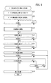
図3は、本実施形態における故障診断のための作業者の作業並びに車両12、外部診断機14及びサーバ15の処理の全体的な流れの一例を示すフローチャートである。図4は、図3の作業及び処理において用いられるデータ項目Idataを説明する図である。
[3. Fault diagnosis]
Next, various operations and processes related to failure diagnosis in the present embodiment will be described.
(3-1. Overall flow)
FIG. 3 is a flowchart showing an example of the overall flow of the worker's work for failure diagnosis and the processing of the
図3のステップS1、S2は、事前準備の段階での処理であり、ステップS3〜S6は、車両12にデータ収集装置18を接続して実際にデータDを収集する段階での処理であり、ステップS7〜S9は、データDの収集後において車両12からデータ収集装置18を取り外して、故障原因を解析する段階での処理である。
Steps S1 and S2 in FIG. 3 are processes in the preliminary preparation stage, and steps S3 to S6 are processes in the stage of actually collecting the data D by connecting the
ステップS1において、外部診断機14(本体16及びデータ収集装置18)では、駆動源に関する車両12の種類(以下「車両種類Cv」又は「種類Cv」ともいう。)と、診断対象部位に関するECU20の種類(以下「ECU種類Cecu」又は「種類Cecu」ともいう。)を作業者からの入力に基づいて設定する。
In step S1, the external diagnostic machine 14 (
選択され得る車両種類Cvには、例えば、ガソリン車、ディーゼル車、ハイブリッド車が含まれる。取得対象として指定され得るECU種類Cecuには、例えば、エンジンECU、モータECU、トランスミッションECU等の多数のECUが含まれる。 The vehicle types Cv that can be selected include, for example, gasoline vehicles, diesel vehicles, and hybrid vehicles. The ECU types Cecu that can be designated as acquisition targets include, for example, a large number of ECUs such as an engine ECU, a motor ECU, and a transmission ECU.
ステップS2において、外部診断機14では、本体16のデータ項目DB70に含まれるデータ項目Idataの中から、種類Cv、Cecuに対応するもの(以下「収集項目候補Iop」という。)を抽出して、データ収集装置18のデータ項目DB120に記憶する(図4参照)。これにより、種類Cv、Cecuに対応する収集項目候補Iopが特定される。
In step S 2, the external
続くステップS3〜S6において、車両12に取り付けられたデータ収集装置18を用いて、実際にデータDの収集が行われる。すなわち、ステップS3において、データ収集装置18は、車両12からVINを取得する。
In subsequent steps S <b> 3 to S <b> 6, data D is actually collected using the
ステップS4において、データ収集装置18は、事前準備の際(S1)に設定されたECU種類Cecuに属する複数のECU20のうち、診断対象の車両12に実際に搭載されているECU20(すなわち、対象ECU20tar)の識別情報(ID)を特定する。この際、データ収集装置18は、ECU種類Cecuに属する複数のECU20それぞれのIDを特定し、いずれのIDを有するECU20が車両12に搭載されているかを、通信によって各ECU20に問い合わせる。以下では、車両12に実際に搭載されているECU20(対象ECU20tar)のIDを「IDins」ともいう。
In step S4, the
ステップS5において、データ収集装置18は、事前準備の際(S2)に抽出(又は記憶)した収集項目候補Iopのうち、ステップS4で搭載されているECU20(搭載ECU20ins)として特定したIDinsに対応するECU20が装備しているものを、実際に収集するデータDの項目(以下「収集項目Idet」という。)として設定する(図4参照)。これにより、実際の収集項目Idetを搭載ECU20insに対応して自動的に設定することが可能となる。
In step S5, the
ステップS6において、データ収集装置18は、ステップS5で設定した収集項目Idetについて、車両12から運転パラメータデータDを収集する。データDの収集期間は、通常、1週間程度であるが、特定することが困難な故障原因を診断する場合、長期に亘る場合もある。
In step S6, the
データDの収集が終了すると、ステップS7〜S9において、データ収集装置18が収集したデータDを外部診断機14の本体16に読み込んで、故障原因の解析が行われる。まずステップS7において、外部診断機14の本体16では、データDの収集時(S3)において取得したVINに対応するECU20(すなわち、対象ECU20tar)のID及び出力可能項目Iout(以下「収集予定項目Iex」ともいう。)を特定する。
When the collection of the data D is completed, in steps S7 to S9, the data D collected by the
本実施形態では、インターネット環境で接続可能なサーバ15において、車両12毎のECU搭載データを、VINに対応させて記憶した車両DB130が設けられている。本体16は、データ収集装置18からVINを取得した後、サーバ15にVINを通知する。サーバ15は、通知されたVINに対応するECU20(すなわち、対象ECU20tar)のIDvin及び出力可能項目Ioutを車両DB130から読み出して本体16に通知する(なお、以下の記載では、VINに対応する対象ECU20tarのIDをIDvinともいう。)。
In the present embodiment, the
ステップS8において、本体16は、データ収集装置18が車両12から取得したIDins(S4)及びこれに基づく収集項目Idet(S5)と、サーバ15から取得したIDvin及び出力可能項目Iout(S7)とを比較する(図4参照)。
In step S8, the
ステップS9において、本体16は、ステップS8での比較結果を出力する。車両12から実際に収集した収集項目Idetが、車両12のVINで確認した搭載ECU20insに対応する出力可能項目Ioutに対して不足している場合、不足している収集項目Idetについての通信異常があったと推定し、対象ECU20tarに故障が発生していると判定可能である。また、収集項目Idetと出力可能項目Ioutとが同じであれば、データ収集装置18と各対象ECU20tarとの通信異常はない。そこで、作業者は、データ収集装置18が収集し、その後、診断機本体16に読み込んだデータDに基づいて診断作業を行う。
In step S9, the
(3−2.事前準備)
(3−2−1.事前準備の全体的な流れ)
図5は、運転パラメータデータDの収集のための事前準備としての作業者の作業並びに診断機本体16及びデータ収集装置18の処理の一例を示すフローチャートである。図5の内容は、図3のステップS1、S2をより詳細に示したものである。図5のステップS11において、作業者(テクニシャン等)は、データ収集装置18のコネクタ94を診断機本体16のコネクタ58に接続する。
(3-2. Advance preparation)
(3-2-1. Overall flow of advance preparation)
FIG. 5 is a flowchart showing an example of a worker's work as a preliminary preparation for collecting the operation parameter data D and processing of the diagnostic machine
ステップS12において、作業者は、診断機本体16の入出力部50(マウス、キーボード等)を操作して、運転パラメータデータDの収集に用いる診断ソフトウェアを起動する。これに伴い、診断機本体16は、データDの収集に関する表示画面200(以下「入力画面200」ともいう。)(例えば図6)を表示部56に表示する。ステップS11、S12の順番は逆であってもよい。
In step S <b> 12, the operator operates the input / output unit 50 (mouse, keyboard, etc.) of the diagnostic machine
ステップS13において、作業者は、表示画面200への入力によりデータ収集条件を入力する(詳細は後述する。)。 In step S13, the worker inputs data collection conditions by inputting to the display screen 200 (details will be described later).
ステップS14において、作業者は、表示画面200を介しての入力により診断機本体16とデータ収集装置18との間での通信を確立することを要求する。当該要求を受けた本体16(データ収集装置通信機能62)は、データ収集装置18との間で通信を確立する。なお、ステップS13、S14の順番は反対でもよい。
In step S <b> 14, the worker requests establishment of communication between the diagnostic machine
ステップS15において、作業者は、表示画面200を介しての入力によりデータ収集装置18のデータ収集条件の変更を本体16に要求する。当該要求を受けた本体16(収集条件送信機能66)は、データ収集装置18のデータ収集条件を、ステップS13で入力されたものに変更する。すなわち、本体16は、新たなデータ収集条件をデータ収集装置18に送信し、データ収集装置18(収集条件読込み機能104)は、受信したデータ収集条件を新たなデータ収集条件として設定する。
In step S <b> 15, the worker requests the
ステップS16において、作業者は、表示画面200を介しての入力により診断機本体16とデータ収集装置18との間での通信を切断することを要求する。当該要求を受けた本体16(データ収集装置通信機能62)は、データ収集装置18との間で通信を切断する。
In step S <b> 16, the worker requests that communication between the diagnostic machine
ステップS17において、作業者は、データ収集装置18のコネクタ94を診断機本体16のコネクタ58から取り外す。
In step S <b> 17, the operator removes the
(3−2−2.データ収集条件)
(3−2−2−1.データ収集条件の概要)
図5のステップS13で入力されるデータ収集条件は、例えば、ネットワークの種類{CAN、LIN、FlexRay、Kライン等の別及び複数のCAN(高速CAN、低速CAN等)がある場合、それらの別}、データ収集を中断及び再開するバス使用率及び対象ECU20tarの種類(又は診断対象部位)を含む。加えて、特許文献3に記載の内容(例えば、データDの連続的な取得を行う時間(連続的データ取得時間)、データDの連続的な取得を行う周期(連続的データ取得周期)又はデータDの収集にかける総時間(データ収集総時間))を指定してもよい。
(3-2-2. Data collection conditions)
(3-2-2-1. Overview of data collection conditions)
The data collection conditions input in step S13 in FIG. 5 include, for example, network types {CAN, LIN, FlexRay, K line, etc., and if there are multiple CANs (high speed CAN, low speed CAN, etc.) }, Including the bus usage rate for interrupting and resuming data collection and the type (or diagnosis target part) of the target ECU 20tar. In addition, the contents described in Patent Document 3 (for example, time for continuously acquiring data D (continuous data acquisition time), period for continuously acquiring data D (continuous data acquisition period), or data The total time for collecting D (total time for data collection)) may be specified.
さらに、図3のステップS1、S2に関連して述べた通り、図5のステップS13で入力されるデータ収集条件には、駆動源に関する車両12の種類(車両種類Cv)と、診断対象部位に関するECU20の種類(ECU種類Cecu)が含まれる。 Furthermore, as described in relation to steps S1 and S2 in FIG. 3, the data collection conditions input in step S13 in FIG. 5 include the type of vehicle 12 (vehicle type Cv) related to the drive source and the diagnosis target region. The type of ECU 20 (ECU type Cecu) is included.
演算部52は、入力された種類Cv、Cecuに対応するデータ項目Idataをデータ項目DB70から抽出し、データ収集装置18に送信するデータ収集条件の一部とする。
The
なお、ECU種類Cecuは、ユーザから聞き出した故障の症状に基づいて推定される故障原因に対応するデータDを出力するECU20の種類である。後に図7を参照して詳述するように、ECU種類Cecuに含まれるECU20は複数存在するが、特定の車両12においてECU種類Cecuに含まれるECU20は1つしかない。このため、入力された種類Cecuに基づいて抽出されるデータ項目Idataは、入力された種類Cecuに含まれる複数のECU20が取得可能なデータDの項目全てに対応する(図4参照)。
The ECU type Cecu is a type of the ECU 20 that outputs data D corresponding to the cause of failure estimated based on the failure symptom heard from the user. As will be described in detail later with reference to FIG. 7, there are a plurality of ECUs 20 included in the ECU type Cecu, but there is only one ECU 20 included in the ECU type Cecu in a
(3−2−2−2.実行ファイル)
作業者が診断機本体16においてデータ収集条件を入力することで、データ収集装置18が実行するプログラム(実行ファイルFexe)が生成される。ここでの実行ファイルFexeは、駆動源に関する車両12の種類Cv毎に生成されるファイルパッケージの形態を取る。
(3-2-2-2. Executable file)
When an operator inputs data collection conditions in the diagnostic machine
前記ファイルパッケージには、次のファイルが含まれる。
(a)VINを取得するためのプログラムファイル(VIN取得ファイルFvin)、及び
(b)各ネットワーク34a、34bのECU20a〜20iからデータDを取得するためのプログラムファイル(データ取得ファイルFdata)
The file package includes the following files.
(A) Program file for acquiring VIN (VIN acquisition file Fvin), and (b) Program file for acquiring data D from the
VIN取得ファイルFvinは、ネットワーク34a、34b毎に設定することができる。例えば、高速CANであるネットワーク34aで用いるファイルFvinを「VIN.unt」として設定する。拡張子「unt」は、VINを取得するためのファイル(プログラム)の拡張子として用いる。
The VIN acquisition file Fvin can be set for each of the
データ取得ファイルFdataは、診断対象部位毎又は対象ECU20tarが属するECU20の種類Cecu毎に設定することができる。複数の診断対象部位を設定する場合、複数のデータ取得ファイルFdataが設定される。例えば、トランスミッションを診断対象部位とする場合(換言すると、ECU種類CecuとしてトランスミッションECUが選択された場合)、ファイルFdataを「MISSION.mam」として設定する。拡張子「mam」は、データDを取得するためのファイル(プログラム)の拡張子として用いる。ファイルFdata用の拡張子は、ネットワーク34a、34b毎に変化させる。
The data acquisition file Fdata can be set for each part to be diagnosed or for each type Cecu of the ECU 20 to which the target ECU 20tar belongs. When a plurality of diagnosis target parts are set, a plurality of data acquisition files Fdata are set. For example, when the transmission is a diagnosis target part (in other words, when the transmission ECU is selected as the ECU type Cecu), the file Fdata is set as “MISSION.mam”. The extension “mam” is used as an extension of a file (program) for acquiring the data D. The extension for the file Fdata is changed for each of the
なお、VIN取得ファイルFvinとデータ取得ファイルFdataを分けることにより、VINを記憶しているECU20(例えば、ECU20a)をデータ取得ファイルFdataの対象から除外することが可能となる。
By separating the VIN acquisition file Fvin and the data acquisition file Fdata, it is possible to exclude the ECU 20 (for example, the
また、実行ファイルFexe(ファイルパッケージ)の種類は、特定の入力画面で設定する。具体的には、後述する入力画面200のハードウェア設定選択部204(図6)において「機種情報/設定ファイル管理」を選択した場合に表示される入力画面(図示せず)において設定する。
The type of the execution file Fexe (file package) is set on a specific input screen. Specifically, the setting is made on an input screen (not shown) displayed when “model information / setting file management” is selected in a hardware setting selection unit 204 (FIG. 6) of the
(3−2−2−3.データ収集条件の入力)
(3−2−2−3−1.入力画面200の概要)
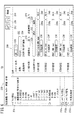
図6は、データ収集条件を入力する際の入力画面200の一例を示す図である。図7は、診断対象部位の種類又は対象ECU20tarが属するECU20の種類(種類Cecu)に応じた各種情報(対象ECU20tarの識別情報(ID)等)の一例を示す図である。図7において、CNG車は、天然ガス(compressed natural gas)自動車を意味し、FFVは、フレックス燃料車(flexible-fuel vehicle)を意味する。
(3-2-2-3. Input of data collection conditions)
(3-2-23-1. Overview of Input Screen 200)
FIG. 6 is a diagram illustrating an example of the
データ収集条件の入力時には、まず駆動源に関する車両12の種類Cv(ガソリン車/CNG車/FFV、ハイブリッド車等)を特定(入力)する。その上で、ユーザの操作により、図6のような入力画面200を表示させる。
When inputting the data collection conditions, first, the type Cv (gasoline vehicle / CNG vehicle / FFV, hybrid vehicle, etc.) of the
図6に示すように、入力画面200は、メニュー選択ボタン202a〜202cと、ハードウェア設定選択部204と、データ収集条件入力部206と、条件入力ボタン208と、接続ボタン210と、データ読込みボタン212とを有する。
As shown in FIG. 6, the
(3−2−2−3−2.メニュー選択ボタン202a〜202c)
メニュー選択ボタン202a〜202cは、複数のメニュー(「ハードウェア設定」、「ハードウェア管理」及び「不具合解析」)を選択するためのボタンである。本実施形態では、データ収集装置18のデータ収集条件を入力する際は、ボタン202a(ハードウェア設定)を選択する。また、後述するデータ解析(図10のS55)を行う際は、ボタン202c(不具合解析)を選択する。
(3-2-2-3-2.
The
(3−2−2−3−3.ハードウェア設定選択部204)
ハードウェア設定選択部204(以下「選択部204」ともいう。)は、入力チャンネル(CH)の設定、出力チャンネルの設定等のハードウェア設定の選択肢をポインタ(図示せず)により選択するための部位である。なお、選択部204は、表示データサイズに応じてスクロール可能としてもよい(データ収集条件入力部206等も同様である。)。
(3-2-2-3-3. Hardware Setting Selection Unit 204)
A hardware setting selection unit 204 (hereinafter also referred to as a “
(3−2−2−3−4.データ収集条件入力部206)
データ収集条件入力部206(以下「入力部206」ともいう。)は、選択部204で選ばれた選択肢に応じて入力欄を表示する部位である。なお、図6の例では、選択部204において出力チャンネルの設定として高速CAN(すなわち、ネットワーク34a)が選択された場合を示している。これに加えて又はこれに代えて、他のネットワーク(例えば、低速CANであるネットワーク34b)について設定を行うこともできる。
(3-2-2-3-4. Data collection condition input unit 206)
The data collection condition input unit 206 (hereinafter also referred to as “
図6に示すように、入力部206は、メッセージ出力設定欄220と、ファイル名入力欄222と、送信条件表示欄224と、送信停止条件入力欄226と、送信再開条件入力欄228と、ECU設定ファイル入力欄230と、読込ボタン232と、保存ボタン234と、ECU選択ボタン236と、ECU設定表示欄238a〜238eと、リセットボタン240とを有する。
As shown in FIG. 6, the
メッセージ出力設定欄220は、データ収集装置18の表示部86に案内メッセージを表示させるか否かを設定する欄である。ファイル名入力欄222は、実行ファイルFexe(ファイルパッケージ)の名称を入力する欄である。送信条件表示欄224は、データ収集装置18がデータ要求信号Sreqの送信を開始する条件(換言すると、データDの収集を開始する条件)を表示する欄である。
The message
送信停止条件入力欄226は、データDを収集中の場合に、データ収集装置18がデータ要求信号Sreqの送信を中断する条件(バス使用率の閾値)を表示する欄である。送信再開条件入力欄228は、データ要求信号Sreqの送信を中断中の場合に、データ収集装置18がデータ要求信号Sreqの送信を再開する条件(バス使用率の閾値)を表示する欄である。
The transmission stop
ECU設定ファイル入力欄230は、データ取得ファイルFdataをテキスト入力する欄である。読込ボタン232は、入力欄230に入力されたファイルFdataを読み込むためのボタンである。ボタン232が押されると、入力欄230に入力されたファイルFdataが、ECU設定表示欄238a〜238eのいずれか空いている欄に表示される。保存ボタン234は、入力部206における選択内容を保存するためのボタンである。
The ECU setting
ECU選択ボタン236は、診断対象部位(又はECU種類Cecu)を入力するためのボタンである。ボタン236が押されると、データ取得ファイルFdataの選択肢が表示され、当該選択肢の中から特定のデータ取得ファイルFdataを選択することができる。本実施形態において、データ取得ファイルFdataの入力又は選択は、ECU種類Cecuの入力又は選択としての意味を持つ。
The
ECU設定表示欄238a〜238eは、データ取得ファイルFdata(すなわち、ECU種類Cecu又は診断対象部位)を表示する。リセットボタン240は、表示欄238a〜238eに表示されているファイルFdataをリセットするためのボタンである。
The ECU
(3−2−2−3−5.条件入力ボタン208、接続ボタン210及びデータ読込みボタン212)
条件入力ボタン208は、データ収集条件を入力するための部位(例えば、データ収集条件入力部206)を表示させるためのボタンである。接続ボタン210は、本体16とデータ収集装置18との通信を確立させ、本体16で入力されたデータ収集条件をデータ収集装置18に出力させるためのボタンである。データ読込みボタン212は、データ収集装置18で収集されたデータDを本体16に読み込ませるためのボタンである。
(3-2-2-3-5.
The
(3−2−2−4.対象ECU20tarの種類Cecu)
上記のように、図6の入力画面200には、ECU種類Cecuを入力するECU選択ボタン236と、種類Cecuを表示するECU設定表示欄238a〜238eとが含まれる。データ収集装置18及び各ECU20a〜20iの処理能力が相対的に高い場合、車両12の全てのECU20に対してデータ収集装置18からデータDを収集することも考えられる。
(3-2-2-4. Type of ECU 20tar Cecu)
As described above, the
しかしながら、データ収集装置18と各ECU20との通信を増加させると、ネットワーク34a、34b内の通信量が膨大となり、ネットワーク34a、34b内での通信が正常に行われなくなるおそれがある。そこで、本実施形態では、車両12について顧客が主張している不具合症状を引き起こす可能性のある部位(診断対象部位)についてのデータDを取得するため、特定可能な対象ECU20tarの数をネットワーク34a、34bの種類に応じて制限する。例えば、ネットワーク34a(高速CAN)に含まれるECU20a〜20fの数が15である場合、ネットワーク34aについて特定可能な対象ECU20tarの数を3〜10のいずれかの値に制限することが可能である。ネットワーク34b(低速CAN)等についても同様である。
However, if communication between the
前記診断対象部位としては、例えば、ガソリン車、CNG車又はFFVであれば、例えば、エンジン、トランスミッション、シフト・レバー、電動パワーステアリング(EPS)機構、反力ペダル機構、アクティブ・コントロール・マウント(ACM)機構、自動クルーズ制御(ACC)機構、メータ類、電動パーキング・ブレーキ機構、音響車両警報システム(AVAS:Acoustic Vehicle Alerting System)、補助拘束システム(SRS:Supplemental Restraint System)及びシートベルト自動締付け装置の全部又は一部が含まれ得る。また、ハイブリッド車又は電気自動車であれば、ガソリン車等の診断対象部位に加え又はこれに代えて、1つ又は複数の走行モータ及びバッテリが含まれ得る。 For example, in the case of a gasoline car, a CNG car or an FFV, the diagnosis target part is, for example, an engine, a transmission, a shift lever, an electric power steering (EPS) mechanism, a reaction force pedal mechanism, an active control mount (ACM). ) Mechanism, automatic cruise control (ACC) mechanism, meters, electric parking and brake mechanism, acoustic vehicle alert system (AVAS), supplemental restraint system (SRS) and automatic seat belt tightening device All or part may be included. In addition, in the case of a hybrid vehicle or an electric vehicle, one or a plurality of travel motors and a battery may be included in addition to or instead of the diagnosis target portion such as a gasoline vehicle.
一般に、車両12では、1つ又は複数の診断対象部位を1つのECU20で制御することが多い。このため、ECU種類Cecuを特定することにより、診断対象部位を特定することとなる。
In general, in the
本実施形態において、ECU種類Cecuを、データDのファイル名で特定する。例えば、ECU種類CecuとしてエンジンECUを選択する場合、ファイル「Gasoline&CNG.mam」又は「Diesel.mam」を選択する(図7参照)。 In the present embodiment, the ECU type Cecu is specified by the file name of the data D. For example, when the engine ECU is selected as the ECU type Cecu, the file “Gasoline & CNG.mam” or “Diesel.mam” is selected (see FIG. 7).
また、ECU種類Cecuが同一であっても、対象ECU20tarのIDは、車種に応じて複数存在する場合がある。例えば、図7では、トランスミッションECUに関し、対象ECU20tarのIDとして「0E」、「1D」及び「1E」が存在する。0Eは、エンジンECUとトランスミッションECUが同一のケース内に配置されていること(換言すると、エンジンECUとトランスミッションECUとが一体的に構成されていること)を示す。1Dは、例えば、オートマチック・トランスミッション(AT)であることを示す。1Eは、例えば、エンジンECUとトランスミッションECUが別個に設けられていることを示す。 Even if the ECU type Cecu is the same, there may be a plurality of IDs of the target ECU 20tar depending on the vehicle type. For example, in FIG. 7, regarding the transmission ECU, “0E”, “1D”, and “1E” exist as IDs of the target ECU 20tar. 0E indicates that the engine ECU and the transmission ECU are arranged in the same case (in other words, the engine ECU and the transmission ECU are integrally configured). 1D indicates, for example, an automatic transmission (AT). 1E indicates that, for example, an engine ECU and a transmission ECU are provided separately.
本実施形態では、ECU種類Cecuが選択されると、種類Cecuに対応する複数のECU20それぞれについての出力可能項目Ioutの全てをECU20のID毎にデータ収集装置18に記憶する。出力可能項目Ioutは、ECU20が出力可能な運転パラメータデータDの項目である。以下では、事前準備の段階で選択及び記憶した出力可能項目Ioutを、収集項目候補Iopという。
In this embodiment, when the ECU type Cecu is selected, all the output possible items Iout for each of the plurality of ECUs 20 corresponding to the type Cecu are stored in the
図7に示す各種情報(換言すると、ECU種類Cecuの指定方法及び利用方法)については、図8及び図9のフローチャートを説明する際に併せて説明する。 Various information shown in FIG. 7 (in other words, a method for specifying and using the ECU type Cecu) will be described together with the description of the flowcharts of FIGS. 8 and 9.
(3−3.運転パラメータデータDの収集時の作業及び処理)
(3−3−1.運転パラメータデータDの収集時の全体的な流れ)
図8は、運転パラメータデータDの収集時における作業者の作業及びデータ収集装置18の処理の一例を示すフローチャートである。図8の内容は、図3のステップS3〜S6をより詳細に示したものである。図8並びに後述する図9、図10及び図12におけるデータ収集装置18の処理は、演算部82が実行する。また、特定することが困難な故障原因を診断する場合、データDの収集は、比較的長期(例えば、1〜2週間)に亘る。
(3-3. Work and processing when collecting operation parameter data D)
(3-3-1. Overall flow when collecting operation parameter data D)
FIG. 8 is a flowchart illustrating an example of the work of the worker and the processing of the
図8のステップS21において、作業者(テクニシャン等)は、データ収集装置18のコネクタ94を車両12のデータリンクコネクタ38に接続する。バッテリ24からデータ収集装置18までの電力線37、92には、特段のスイッチは設けられていない(但し、ヒューズを設けることが好ましい。)。このため、コネクタ38、94を接続すると、車両12のバッテリ24からの電力がデータ収集装置18に供給されて、データ収集装置18が起動される(ステップS22)。この際、バッテリ24からの電力は、データ収集装置18のキャパシタ88に充電され、コネクタ94が取り外された際も、データ収集装置18をある程度の時間作動させ続けることが可能となる。
In step S <b> 21 of FIG. 8, an operator (technician or the like) connects the
なお、データ収集装置18に図示しない収録可否スイッチを設け、作業者が当該スイッチを操作することでデータ収集装置18に対してデータ収録可否の選択を行えるような構成としてもよい。また、データ収集装置18を長時間作動させることが可能な電源をデータ収集装置18自体に設けてもよい。
The
データ収集装置18は、コネクタ94の接続後、初めて電力が供給された場合、初期化を行う。ここでの初期化は、データDの保存ファイルFsaveを新たに作成し直す。すなわち、コネクタ94が取り外された後、再接続された場合、新たな保存ファイルFsaveを作成する。これにより、作業者は、コネクタ94の抜き差しのみにより、診断対象の車両12を切り替えることが可能となる。この場合、各保存ファイルFsaveは、新たに作成される。
The
図8のステップS23において、データ収集装置18は、IGSW40がオンになったか否かを判定する。当該判定は、ネットワーク34aを介して第1ECU20aから通知を受けることにより行う。IGSW40がオンでない場合(S23:NO)、ステップS23を繰り返す。
In step S23 of FIG. 8, the
IGSW40がオンになると(S23:YES)、第1ECU20aと共に他のECU20b〜20iが起動する。この際、データ収集装置18は、各ECU20a〜20iとの通信を確立する。なお、ECU20a〜20iのいずれか(例えば、イモビライザECUに対応するもの)については、IGSW40がアクセサリ(ACC)の位置に来たときに起動する。
When the
ステップS24において、データ収集装置18(要求信号特定機能108)は、初期設定処理を実行する。初期設定処理は、各対象ECU20tarにおいて出力可能なデータDの項目(出力可能項目Iout)を確認し、データ収集装置18が対象ECU20tarから取得するデータDの項目(以下「収集項目Idet」という。)として出力可能項目Ioutを設定する処理である。初期設定処理は、データ収集装置18の初期化(S22)に伴って実行されるものである。このため、データ収集装置18が車両12から取り外されるまでは、新たな初期設定処理は実行されない。初期設定処理の詳細は、図9を参照して後述する。
In step S24, the data collection device 18 (request signal specifying function 108) executes an initial setting process. In the initial setting process, an item of data D (outputtable item Iout) that can be output in each target ECU 20tar is confirmed, and an item of data D that the
続くステップS25において、データ収集装置18は、作業者にIGSW40のオフを求める要求を表示部86に表示させる。IGSW40がオンのままである場合(S26:NO)、ステップS25に戻り、当該要求を継続する。IGSW40がオフになった場合(S26:YES)、ステップS27において、データ収集装置18は、作業者にIGSW40のオン(再オン)を求める要求を表示部86に表示させる。IGSW40がオフのままである場合(S28:NO)、ステップS27に戻り、当該要求を継続する。IGSW40がオンされた場合(S28:YES)、ステップS29において、データ収集装置18は、データ収集処理を実行する。
In subsequent step S25, the
データ収集処理では、データ収集装置18から各対象ECU20tarに対してデータ要求信号Sreqが送信される。データ要求信号Sreqは、要求信号特定機能108により特定され、データ要求機能110により送信される。データ要求信号Sreqを受信した対象ECU20tarは、データ要求信号Sreqで要求されたデータDをデータ収集装置18に返信する。データ収集装置18のデータ受信・記憶機能112は、各対象ECU20tarからのデータDを受信し、記憶部84(データ記憶部)に記憶する。データ収集処理の詳細は、例えば、特許文献3に記載のものを用いることができる。
In the data collection process, a data request signal Sreq is transmitted from the
ステップS30において、データ収集装置18は、IGSW40がオフされたか否かを判定する。IGSW40がオンのままである場合(S30:NO)、ステップS29に戻り、データ収集装置18は、データ収集処理を継続する。IGSW40がオフされた場合(S30:YES)、車両12は停止中であるが、コネクタ38、94が接続中のままである。このため、データ収集装置18にはバッテリ24からの電力供給が継続される。この場合、ステップS31に進む。
In step S30, the
ステップS31において、データ収集装置18は、コネクタ94が取り外されたか否かを判定する。当該判定は、例えば、通信バス36a、36bと接続された通信線90における信号出力を監視することにより行う。
In step S31, the
コネクタ94が取り外されていない場合(S31:NO)、ステップS32において、データ収集装置18は、IGSW40がオンされたか否かを判定する。IGSW40がオフのままである場合(S32:NO)、ステップS31に戻る。IGSW40がオンされた場合(S32:YES)、ステップS29に戻り、データ収集装置18は、データ収集処理を再開する。従って、コネクタ38、94が接続され続けている間、IGSW40がオンであれば(S32:YES)、データ収集装置18はデータDの収集を行う(S29)。
When the
この際、初期設定処理(S24)で設定した収集項目Idetを用いる。また、コネクタ38、94が接続され続けている間、IGSW40がオフであれば(S30:YES)、データ収集装置18はデータDの収集を中止して待機状態(又はスリープ状態)となる。
At this time, the collection item Idet set in the initial setting process (S24) is used. If the
ステップS31に戻り、コネクタ94が取り外された場合(S31:YES)、バッテリ24からデータ収集装置18への電力供給は終了する。この場合、ステップS33において、データ収集装置18は、終了処理を実行する。終了処理では、それまでに取得したデータDを保存ファイルFsaveに保存する等の処理を行う。終了処理を実行する際の電力は、キャパシタ88から供給される。また、保存ファイルFsaveへのデータDの保存は、データ収集処理(S29)の間も行うことが可能である。
Returning to step S31, when the
なお、IGSW40をオフにすることなくコネクタ94が取り外された場合も、同様に、データ収集装置18は、終了処理(S33)を実行してもよい。
Even when the
(3−3−2.初期設定処理)
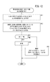
図9は、本実施形態における初期設定処理のフローチャート(図8のS24の詳細)である。ステップS41において、データ収集装置18は、ネットワーク34を介して特定のECU20(例えば、ECU20a)からVINを取得する。この際、データ収集装置18(演算部82)は、VIN取得ファイルFvin(例えば、「VIN.unt」)を実行する。
(3-3-2. Initial setting process)
FIG. 9 is a flowchart of the initial setting process in this embodiment (details of S24 in FIG. 8). In step S41, the
具体的には、データ収集装置18は、ファイルFvinで指定されたネットワーク34(例えば、ネットワーク34a)に対してVINの出力要求指令Sreqvinを出力する。当該指令Sreqvinを受信した各ECU20a〜20fは、自己がVINを記憶しているか否かを確認する。そして、VINを記憶しているECU20は、データ収集装置18に対してVINを送信する。なお、本実施形態において、VINを記憶しているECU20は1つのみである。また、VINを記憶しているECU20が予め特定可能である場合、データ収集装置18は、当該ECU20に対してVINを要求してもよい。
Specifically, the
取得したVINは、データ解析(図10のS55)の際に用いられる。すなわち、データ収集装置18は、取得したVINを記憶部84に記憶しておき、後に診断機本体16に出力する。
The acquired VIN is used for data analysis (S55 in FIG. 10). That is, the
ステップS42において、データ収集装置18は、対象ECU20tarのID(すなわち、IDins)を特定する。上記のように、本実施形態では、ECU種類Cecuが特定されても、種類Cecuに含まれるECU20は、車両12によって異なる場合がある。例えば、図7の例では、トランスミッションECUに関し、IDの候補として「0E」、「1D」及び「1E」の3つが存在する。そこで、データ収集装置18は、この3つのIDを用いて、実際に車両12に搭載されているトランスミッションECUのIDinsを特定する。
In step S42, the
すなわち、データ収集装置18は、3つのIDを宛先として含む1つの応答指令を送信する。そして、データ収集装置18は、所定時間内に返信があった対象ECU20tarのIDをIDinsとして設定する。なお、ネットワーク34bについては、宛先としてECU20を指定した場合であっても、ゲートウェイ22から返信させることも可能である。また、所定時間内にいずれのIDの対象ECU20tarからも返信がなかった場合、データ収集装置18は、いずれのIDの候補についても返信がなかったことを記憶部84に記憶する。
That is, the
図7からもわかるように、本実施形態では、対象ECU20tarのIDの候補は、車両12の種類(ガソリン車等)にかかわらず、共通である。換言すると、対象ECU20tarのIDの候補は、診断対象部位毎(又はECU種類Cecu毎)に区分されている。複数の診断対象部位が存在する場合、診断対象部位毎に対象ECU20tarのIDを特定する。 As can be seen from FIG. 7, in this embodiment, the candidate ID of the target ECU 20tar is common regardless of the type of the vehicle 12 (gasoline vehicle or the like). In other words, the ID candidates for the target ECU 20tar are classified for each diagnosis target part (or for each ECU type Cecu). When there are a plurality of diagnosis target parts, the ID of the target ECU 20tar is specified for each diagnosis target part.
ステップS43において、データ収集装置18は、ステップS42で特定したIDinsに対応する各対象ECU20tarの出力可能項目Ioutを特定する。上記のように、事前準備(図3)の際、ECU種類Cecuが選択されると、種類Cecuに対応する複数のECU20それぞれの出力可能項目Ioutの全てが収集項目候補IopとしてECU20のID毎にデータ収集装置18に記憶される。このため、特定したIDinsに基づいて、当該対象ECU20tarの出力可能項目Ioutを特定することが可能となる。出力可能項目Ioutは、対象ECU20tarが出力可能な運転パラメータデータDの項目である。
In step S43, the
ステップS44において、データ収集装置18は、記憶部84に記憶している収集項目候補Iopのうち、ステップS43で特定した出力可能項目Iout以外のものを除外して収集項目Idetを設定する。収集項目Idetは、データ収集処理(図8のS29)においてデータ収集装置18が実際に収集するデータDの項目である。従って、収集項目候補Iopに含まれるが、出力可能項目Ioutに含まれない項目は、収集項目Idetに設定されない。
In step S44, the
なお、ステップS44では、出力可能項目Ioutがそのまま収集項目Idetとして設定される。また、収集項目Idetの設定に着目した場合、出力可能項目Ioutをそのまま収集項目Idetとして用いることもできる。 In step S44, the output possible item Iout is set as it is as the collection item Idet. Further, when focusing on the setting of the collection item Idet, the output possible item Iout can be used as it is as the collection item Idet.
(3−4.運転パラメータデータDの収集後の作業及び処理)
(3−4−1.全体的な流れ)
図10は、運転パラメータデータDの収集後における作業者の作業及びデータ収集装置18の処理の一例を示すフローチャートである。ステップS51において、作業者(テクニシャン等)は、データ収集装置18のコネクタ94を診断機本体16のコネクタ58に接続する。
(3-4. Work and processing after collection of operation parameter data D)
(3-4-1. Overall flow)
FIG. 10 is a flowchart showing an example of the work of the worker after the collection of the operation parameter data D and the processing of the
ステップS52において、作業者は、診断機本体16の入出力部50(マウス、キーボード等)を操作して、運転パラメータデータDの取得に用いる診断ソフトウェアを起動する。これに伴い、診断機本体16は、データDの取得に関する表示画面300(以下「診断画面300」又は「画面300」ともいう。)(図11)を表示部56に表示する。ステップS51、S52の順番は逆であってもよい。
In step S <b> 52, the operator operates the input / output unit 50 (mouse, keyboard, etc.) of the diagnostic machine
ステップS53において、作業者は、表示画面300を介しての入力により診断機本体16とデータ収集装置18との間での通信を確立することを要求する。当該要求を受けた本体16(データ収集装置通信機能62)は、データ収集装置18との間で通信を確立する。
In step S <b> 53, the worker requests establishment of communication between the
ステップS54において、作業者は、表示画面300を介しての入力により診断機本体16に対し、収集した運転パラメータデータDをデータ収集装置18から取得することを要求する。当該要求は、例えば、データ読込みボタン212(図6)を介して行う。当該要求を受けた本体16(収集データ読出し機能68)は、データ収集装置18に対し、収集した運転パラメータデータDを送信することを要求する。当該要求を受けたデータ収集装置18(収集データ送信機能106)は、本体16に対し、収集した運転パラメータデータD(VIN及び収集項目Idetを含む。)を送信する。データ収集装置18からデータDを受信した本体16(収集データ読出し機能68)は、当該データDを記憶部54に保存する。
In step S <b> 54, the operator requests the diagnostic machine
ステップS55において、作業者は、本体16の表示画面300を操作して運転パラメータデータDの解析を行い、故障原因を特定する。ここでの解析には、異常が発生しているECU20(異常ECU20mal)の判定が含まれる。異常ECU20malの判定における外部診断機14側の処理は、主として、診断機本体16のデータ解析機能64により行われる。
In step S55, the operator operates the
なお、ステップS55のデータ解析に際しては、VINを利用した解析を行うことも可能である。具体的には、事前準備において設定するデータ収集条件には、ECU種類Cecuが含まれる(図5のS13、S15)。また、データ収集時には、複数のIDを宛先として含む1つの応答指令を送信して対象ECU20tarのIDを特定する(図9のS42、図7)。この際、所定時間内にいずれのIDの対象ECU20tarからも返信がなかった場合、データ収集装置18は、いずれのIDの候補についても返信がなかったことを記憶部84に記憶する。
In the data analysis in step S55, it is also possible to perform analysis using VIN. Specifically, the ECU type Cecu is included in the data collection conditions set in preparation (S13, S15 in FIG. 5). Further, at the time of data collection, one response command including a plurality of IDs as destinations is transmitted to identify the ID of the target ECU 20tar (S42 in FIG. 9, FIG. 7). At this time, if there is no reply from the target ECU 20tar of any ID within the predetermined time, the
このように、いずれのIDの候補についても返信がなかった場合、実際に車両12が当該種類のECU20を搭載していないのか、それともECU20の故障により返信がなかったのかを確認することができない。
Thus, when there is no reply for any candidate ID, it cannot be confirmed whether the
そこで、本実施形態では、診断対象の車両12(以下「診断対象車両12tar」という。)に搭載されているECU20の情報を、VINを介して特定する。そして、診断対象車両12tarに実際に当該種類のECU20が搭載されていなかったのか、それとも、診断対象車両12tarに当該種類のECU20が搭載されているが、故障により応答がなかったのかを確認することができる。 Thus, in the present embodiment, information of the ECU 20 mounted on the diagnosis target vehicle 12 (hereinafter referred to as “diagnosis target vehicle 12tar”) is specified via the VIN. Then, whether the type of ECU 20 is actually mounted on the diagnosis target vehicle 12tar or whether the type of ECU 20 is mounted on the diagnosis target vehicle 12tar but there is no response due to a failure is confirmed. Can do.
上記のような確認を行うため、作業者は、診断対象車両12tarに搭載されているECU20の種類をVINに基づいて特定する。具体的には、作業者は、図示しない表示画面を介してサーバ15に対して、診断対象車両12tarに搭載されているECU20(以下「搭載ECU20ins」という。)の情報を求める要求(以下「搭載ECU情報要求Riecu」又は「要求Riecu」)を入力する。当該要求Riecuが入力された診断機本体16は、サーバ15に対して要求Riecuと診断対象車両12tarのVINを出力する。要求Riecu及びVINを受信したサーバ15は、受信したVINに対応する搭載ECU20insの情報を出力する。
In order to perform the confirmation as described above, the worker specifies the type of the ECU 20 mounted on the diagnosis target vehicle 12tar based on the VIN. Specifically, the operator requests the
搭載ECU20insの情報を受信した診断機本体16は、搭載ECU20insに含まれているにもかかわらず、データDが収集されていないECU20の出力可能項目Ioutについては、強調表示する。
The
(3−4−2.診断時の表示)
図11は、収集項目Idetと出力可能項目Ioutとの比較結果を表示する本体16の表示画面300の一例を示す。画面300には、詳細表示部302が含まれる。
(3-4-2. Display at diagnosis)
FIG. 11 shows an example of the
詳細表示部302は、データ収集装置18から取得したデータDの詳細を表示するための部位である。詳細表示部302は、送信周期欄310と、カテゴリ欄312と、データ項目欄314と、説明欄316と、単位欄318と、チェック欄320とを含む。
The
詳細表示部302に表示されるデータ項目Idataは、収集項目候補Iop及び収集項目Idetの両方である。収集項目候補Iop及び収集項目Idetは、いずれもデータ収集装置18から取得することが可能である。或いは、収集項目候補Iopは、データ項目DB70又は車両DB130を用いて、データ収集装置18から取得したVIN及びデータ取得ファイルFdataのファイル名に基づいて特定することも可能である。
The data item Idata displayed on the
送信周期欄310は、データ収集装置18によるデータ要求信号Sreqの送信周期を表示する欄である。カテゴリ欄312は、車両12のカテゴリを表示する欄である。図11では、カテゴリとして、駆動源に関する車両12の種類(車両種類Cv)を用いている。
The
データ項目欄314は、データ項目Idataを表示する欄である。説明欄316は、データ項目欄314に表示されたデータ項目Idataの説明を表示する欄である。単位欄318は、データDの単位を表示する欄である。
The
チェック欄320は、出力可能項目Ioutのうち収集項目Idet(データ収集装置18が実際に取得したデータDの項目)が存在するものがチェックされ、収集項目Idetが存在しないものがチェックされない欄である。ここでのチェックは、データ収集装置18からの出力(収集項目Idetと出力可能項目Ioutの比較結果)を用いて行うことができる。或いは、本体16の演算部52が収集項目Idetと出力可能項目Ioutを比較してチェックを行うことも可能である。
The
上記のように、図9のステップS44では、出力可能項目Ioutがそのまま収集項目Idetとして設定される。対象ECU20tar又はゲートウェイ22から送信される出力可能項目Ioutには欠落がある可能性がある。そのような場合、欠落している項目が、不具合症状の原因であることも考えられる。
As described above, in step S44 of FIG. 9, the output possible item Iout is set as it is as the collection item Idet. There is a possibility that the output possible item Iout transmitted from the target ECU 20tar or the
そこで、作業者は、チェック欄320の表示内容を確認することで、欠落している出力可能項目Ioutを特定し、故障診断に生かすことが可能となる。すなわち、作業者は、出力可能項目Ioutとして表示されているにもかかわらず、チェック欄320がチェックされていないデータ項目Idataについては、異常が発生していると判定すること(換言すると、当該データ項目IdataのデータDを出力するはずのECU20に異常が発生していると判定すること)が可能である。以下では、そのような異常が発生しているECU20を異常ECU20malともいう。
Therefore, the operator can identify the missing output possible item Iout by confirming the display content of the
なお、本体16は、上記のような欠落項目を強調表示してもよい。ここにいう強調表示とは、例えば、色の変化、輝度の増加又は文字若しくは背景の点滅等を用いることができる。これに加えて又はこれに代えて、欠落項目とこれに関連して想定される故障原因とを組み合わせてデータベースとして記憶部54に記憶しておき、欠落項目に対応する故障原因を表示又は外部出力してもよい。
The
(3−4−3.異常ECU20malの判定)
図12は、異常ECU20malの判定に伴う作業者の作業及び診断機本体16の処理のフローチャートである。図12における診断機本体16の処理は、演算部52により実行される。ステップS61において、作業者が診断の開始を指令すると、本体16は、データDの収集時において取得したVINに対応するECU20(すなわち、対象ECU20tar)のID(IDvin)及び出力可能項目Ioutを特定する。
(3-4-3. Determination of Abnormal ECU 20mal)
FIG. 12 is a flowchart of the worker's work accompanying the determination of the abnormality ECU 20mal and the processing of the diagnostic machine
ステップS62において、診断機本体16は、データ収集装置18が車両12から取得したIDins(S4)及びこれに基づく収集項目Idet(S5)と、VINに対応するIDvin及び出力可能項目Iout(S7)とを比較する(図4参照)。
In step S62, the diagnostic machine
全てのIDins及び収集項目Idetと、全てのIDvin及び出力可能項目Ioutとが一致する場合(S63:YES)、ステップS64において、本体16は、当該対象ECU20tarが正常であると判定し、正常時の表示を行う。
When all the IDins and the collection items Idet match all the IDvins and the outputable items Iout (S63: YES), in step S64, the
IDinsの一部とIDvinの一部が一致しない場合又は収集項目Idetの一部と出力可能項目Ioutの一部が一致しない場合(S63:NO)、ステップS65において、本体16は、当該対象ECU20tarが異常であると判定する。この場合、本体16は、対になるIDinsが存在しないIDvin又は対になる収集項目Idetが存在しない出力可能項目Ioutを画面300において強調表示する。
When a part of IDins and a part of IDvin do not match, or a part of the collection item Idet and a part of the outputable item Iout do not match (S63: NO), in step S65, the
[4.本実施形態の効果]
以上のように、本実施形態によれば、収集項目Idetの設定の少なくとも一部をデータ収集装置18が行うため(図3のS5、図9のS44)、収集項目Idetの設定に伴う作業者の工数を削減することが可能となる。また、車両12から通知された搭載ECU20insを対象ECU20tarとして識別すると共に(図3のS4、図9のS42)、当該対象ECU20tarに対応する出力可能項目Ioutを収集項目Idetとして設定する(図3のS5、図9のS44)。このため、収集項目Idetの設定に伴う作業者の人為的なミスを防止することが可能となる。
[4. Effects of this embodiment]
As described above, according to the present embodiment, since the
本実施形態において、データ収集装置18の要求信号特定機能108(収集項目設定部)は、データ収集装置18を車両12に接続した状態でのIGSW40(起動スイッチ)の初回オン操作(図8のS23:YES)に対応して、診断機本体16(種類設定部)で設定したECU種類Cecu(対象ECU20tarの種類)毎に搭載ECU20insの有無を車両12に問い合わせて(図8のS24、図9のS42)収集項目Idetを設定する(図3のS5、図9のS44)。さらに、データ収集装置18のデータ要求機能110及びデータ受信・記憶機能112(データ収集管理部)は、IGSW40のオフ操作及びその後の再オン操作が行われたことを条件として(図8のS26:YES→S28:YES)、データ要求信号Sreqの送信及びデータDの記憶を開始する。
In the present embodiment, the request signal specifying function 108 (collection item setting unit) of the
上記によれば、収集項目Idetの設定の少なくとも一部及び運転パラメータデータDの収集開始は、車内ネットワーク34a、34bに対するデータ収集装置18の接続と、IGSW40(起動スイッチ)の操作とにより行うことができる(図8及び図9)。従って、作業者は、収集項目Idetの設定の少なくとも一部及びデータDの収集開始を簡易な操作で行うことが可能となる。
According to the above, at least a part of the setting of the collection item Idet and the collection start of the operation parameter data D can be performed by connecting the
本実施形態において、車内ネットワーク34a、34bに対するデータ収集装置18の接続が一旦解除された場合(図8のS31:YES)には、新たな車内ネットワーク34a、34bに接続(S21)後のIGSW40の初回オン操作(S23:YES)に対応して新たな対象ECU20tarを設定する(図8のS24、図9のS42)。これに続いて、要求信号特定機能108(収集項目設定部)は、新たな収集項目Idetを設定する(図8のS24、図9のS44)。
In this embodiment, when the connection of the
これにより、データ収集装置18をある車両12(第1車両)から取り外して他の車両12(第2車両)に付け替えることで、診断対象車両12tarを容易に変更することが可能になる。
Thus, the diagnosis target vehicle 12tar can be easily changed by removing the
本実施形態において、データ収集装置18と車内ネットワーク34a、34bとの接続は、データ収集装置18のコネクタ94と車両12のデータリンクコネクタ38の接続を介して行われる(図1)。また、データ収集装置18は、コネクタ94とデータリンクコネクタ38を介したバッテリ24(車載電源)からの供給電力により起動する(図8のS22)。
In the present embodiment, the connection between the
これにより、データ収集装置18の起動タイミングを、データリンクコネクタ38への接続時とすることができる。従って、診断対象車両12tarの変更のためのデータリンクコネクタ38へのコネクタ94の着脱に伴ってデータ収集装置18の再起動を行うことができ、診断対象車両12tarの変更後もデータ収集装置18を簡単に作動させることが可能となる。
Thereby, the start timing of the
本実施形態において、診断機本体16(種類設定部)は、駆動源に関する車両12の種類毎に区分されたECU種類Cecuを、作業者の入力に応じて設定する(図3のS1、図7参照)。ここにいう駆動源に関する車両12の種類は、複数の車種を統合し且つ各車種に搭載されているECU20を機能毎の種類として区分したものといえる。
In the present embodiment, the diagnostic machine main body 16 (type setting unit) sets the ECU type Cecu classified according to the type of the
作業者にとって駆動源に関する車両12の種類Cv(ガソリン車、ディーゼル車、ハイブリッド車等)は容易に判別することが可能である。その一方、当該車両12の種類Cvに応じて運転パラメータデータDの項目は大きく相違する。本実施形態では、車両種類Cvについては作業者(ユーザ)が指定し、データ収集装置18は、作業者が指定した種類Cvに応じた範囲に含まれる収集項目候補Iopを用いる(図3のS1、S2、S4、S5)。これにより、作業者による入力負担の軽減又は入力ミスの防止を図りつつ、データ収集装置18における演算負荷及びこれに伴う作業者の工数削減を図ることが可能となる。
The operator can easily determine the type Cv (gasoline vehicle, diesel vehicle, hybrid vehicle, etc.) of the
B.変形例
なお、本発明は、上記実施形態に限らず、本明細書の記載内容に基づき、種々の構成を採り得ることはもちろんである。例えば、以下に示す構成を採ることができる。
B. Modifications It should be noted that the present invention is not limited to the above-described embodiment, and it is needless to say that various configurations can be adopted based on the description of the present specification. For example, the following configuration can be adopted.
[1.適用対象]
上記実施形態では、外部診断機14を車両12に用いたが、これに限らず、例えば、複数のECU20が接続されたローカルネットワークを備えるスタンドアロン型の機器(例えば、船舶、航空機等の移動物体、各種の製造装置)に用いることもできる。
[1. Applicable to]
In the above embodiment, the external
[2.車両12]
上記実施形態では、車内ネットワーク34a、34bとしてCANを用いたが、これに限らず、LIN、FlexRay、Kライン等のネットワークであってもよい。
[2. Vehicle 12]
In the above embodiment, CAN is used as the in-
上記実施形態では、IGSW40がロータリスイッチであることを前提として説明した。しかしながら、IGSW40は、プッシュ式のもの等、実際のデータ収集の診断対象車両12tarに備えられているスイッチであってもよい。なお、IGSW40は、狭義には点火スイッチを意味し、エンジンを有する車両12で用いられるものであるが、ここでは、車両12の起動スイッチを意味し、車両12がEVであっても同様の方法で利用可能である。
The above embodiment has been described on the assumption that the
[3.外部診断機14]
(3−1.診断目的)
上記実施形態では、外部診断機14は車両12の故障診断を行うものであったが、データ収集装置18により運転パラメータデータDを収集する観点からすれば、その他の車両診断を行うものであってもよい。例えば、外部診断機14は、各車載機器の劣化状態又は動作状態を確認する健康診断や、運転者の運転技能(例えば、アクセル操作、ブレーキ操作)を診断する運転技能診断を行うものであってもよい。このため、運転パラメータデータDも故障診断を目的するデータに限らず、その他の診断で用いるデータであってもよい。
[3. External diagnostic machine 14]
(3-1. Diagnostic purpose)
In the above embodiment, the external
(3−2.診断機本体16)
上記実施形態では、診断機本体16は、例えば、市販のノート型パーソナルコンピュータ、タブレット型コンピュータ又はスマートフォンから構成し、単一のものとしたが、これに限らない。例えば、本体16は、本体としてのパーソナルコンピュータと、データ収集装置18とのインタフェースとしての子機(中継器)とから構成してもよい。
(3-2. Diagnostic machine body 16)
In the said embodiment, although the diagnostic machine
上記実施形態では、診断機本体16で用いる診断ソフトウェアは、記憶部54に予め記録されていたが、これに限らない。例えば、診断ソフトウェアは、外部(例えば、公衆ネットワークを介して通信可能な外部サーバ)からダウンロードしたもの、又はダウンロードを伴わないいわゆるASP(Application Service Provider)型で実行するものであってもよい。
In the above embodiment, the diagnostic software used in the diagnostic machine
(3−3.データ収集装置18)
(3−3−1.構成)
上記実施形態では、データ収集装置18は、診断機本体16とは別体のものとして構成したが(図1)、本体16内にデータ収集装置18の機能を持たせることもできる。
(3-3. Data Collection Device 18)
(3-3-1. Configuration)
In the above embodiment, the
上記実施形態では、診断機本体16とデータ収集装置18との間の通信及び車両12とデータ収集装置18との間の通信はいずれも有線通信であったが(図1)、一部に無線通信を介することも可能である。例えば、診断機本体16とデータ収集装置18との間を無線通信で行うこともできる。或いは、車内ネットワーク34a、34bに接続された無線通信機(図示せず)を車両12に設けてもよい。この場合、データ収集装置18と当該無線通信機との間で無線通信を行うと共に、当該無線通信機を介してデータ収集装置18が各ECU20と通信することも可能である。
In the above embodiment, the communication between the diagnostic machine
(3−3−2.起動条件)
上記実施形態では、コネクタ94をデータリンクコネクタ38に接続すると、自動的にデータ収集装置18が起動するようにした(図8のS22)。しかしながら、例えば、データ収集装置18を起動させる観点からすれば、これに限らない。例えば、データ収集装置18に図示しない開始スイッチを設け、作業者が当該開始スイッチを操作することでデータ収集装置18をオンするように構成してもよい。また、データ収集装置18を長時間作動させることが可能な電源をデータ収集装置18自体に設けてもよい。
(3-3-2. Startup conditions)
In the above embodiment, when the
(3−3−3.データ収集条件)
上記実施形態では、データDの収集(図8のS29)を開始する条件として、IGSW40のオン、オフ及び再オンを条件とした(S23、S26、S28)。しかしながら、例えば、出力可能項目Ioutを確認して収集項目Idetを設定する観点からすれば、これに限らない。例えば、データDの収集の開示条件を、IGSW40のオン及びオフの後、IGSW40の位置をアクセサリ(ACC)まで移動させたこととすることが可能である。すなわち、ECU20の中には、IGSW40の位置がオンになったときに起動するものと、ACCになったときに起動するものがある場合がある。そこで、データ収集の開始自体は、IGSW40の位置がオフからACCになったときに開始してもよい。
(3-3-3. Data collection conditions)
In the above-described embodiment, the conditions for starting the collection of data D (S29 in FIG. 8) are on, off, and re-on of the IGSW 40 (S23, S26, S28). However, for example, from the viewpoint of confirming the output possible item Iout and setting the collection item Idet, the present invention is not limited to this. For example, the disclosure condition for collecting the data D may be that the position of the
12…車両 16…診断機本体(種類設定部)
18…データ収集装置 20a〜20i…ECU
20ins…搭載ECU 20tar…対象ECU
24…低電圧バッテリ(車載電源) 34a、34b…車内ネットワーク
38…データリンクコネクタ 40…IGSW(起動スイッチ)
84…記憶部(データ記憶部) 94…コネクタ
108…要求信号特定機能(収集項目設定部)
110…データ要求機能(データ収集管理部の一部)
112…データ受信・記憶機能(データ収集管理部の一部)
120…データ項目DB(データ項目記憶部)
Cv…車両種類 Cecu…ECU種類
D…運転パラメータデータ Idet…収集項目
Iop…収集項目候補 Iout…出力可能項目
Sreq…データ要求信号
12 ...
18 ...
20 ins ... mounted ECU 20 tar ... target ECU
24 ... Low voltage battery (on-vehicle power source) 34a, 34b ... In-
84 ... Storage unit (data storage unit) 94 ...
110 ... Data request function (part of the data collection manager)
112 ... Data reception / storage function (part of data collection management unit)
120: Data item DB (data item storage unit)
Cv ... Vehicle type Cecu ... ECU type D ... Operating parameter data Idet ... Collecting item Iop ... Collecting item candidate Iout ... Output possible item Sreq ... Data request signal
Claims (6)
前記データ収集装置は、
作業者からの入力に基づいて前記対象ECUの種類を設定する種類設定部と、
前記複数のECUそれぞれが出力可能な前記運転パラメータデータの項目を、前記複数のECUの識別情報に対応させて記憶するデータ項目記憶部と、
前記種類設定部で設定した前記対象ECUの種類毎に搭載ECUの識別情報を前記車両に問い合わせて、前記識別情報を受信した前記搭載ECUを前記対象ECUとして識別し、前記対象ECUとして識別された前記搭載ECUが出力可能な前記運転パラメータデータの項目を、前記搭載ECUの前記識別情報に基づいて前記データ項目記憶部から読み出して収集項目として設定する収集項目設定部と、
前記収集項目に対応する前記運転パラメータデータを要求する前記データ要求信号を前記対象ECUに対して送信し、前記データ要求信号に対応する前記運転パラメータデータを受信して前記データ記憶部に記憶させるデータ収集管理部と
を備えることを特徴とするデータ収集装置。 A data request signal for requesting operating parameter data indicating an operating state of each part of the vehicle in a state in which it is detachably connected from the outside to an in-vehicle network having a plurality of electronic control units (hereinafter referred to as “ECU”). Vehicle diagnosis that is transmitted to a target electronic control device (hereinafter referred to as “target ECU”) that is at least one of the ECUs, receives the driving parameter data corresponding to the data request signal, and stores it in a data storage unit Data collection device for
The data collection device includes:
A type setting unit for setting the type of the target ECU based on an input from an operator ;
A data item storage unit that stores items of the operation parameter data that can be output by each of the plurality of ECUs in association with identification information of the plurality of ECUs;
Query the identity of the mounted ECU on the vehicle for each type of the target ECU set by the type setting unit identifies the mounted ECU that has received the identification information as the target ECU, it is identified as the target ECU and collecting item setting unit that sets as a collection item is read from the data item storage section on the basis of the items of the mounting ECU said operating parameter data that can be output, the identification information of the mounted ECU,
Data for transmitting the data request signal for requesting the operation parameter data corresponding to the collection item to the target ECU, receiving the operation parameter data corresponding to the data request signal, and storing the data in the data storage unit A data collection device comprising: a collection management unit.
前記データ収集装置は、
前記対象ECUの種類を設定する種類設定部と、
前記複数のECUそれぞれが出力可能な前記運転パラメータデータの項目を、前記複数のECUの識別情報に対応させて記憶するデータ項目記憶部と、
前記種類設定部で設定した前記対象ECUの種類毎に搭載ECUの有無を前記車両に問い合わせて前記搭載ECUを前記対象ECUとして識別し、前記対象ECUとして識別された前記搭載ECUが出力可能な前記運転パラメータデータの項目を、前記搭載ECUの識別情報に基づいて前記データ項目記憶部から読み出して収集項目として設定する収集項目設定部と、
前記収集項目に対応する前記運転パラメータデータを要求する前記データ要求信号を前記対象ECUに対して送信し、前記データ要求信号に対応する前記運転パラメータデータを受信して前記データ記憶部に記憶させるデータ収集管理部と
を備え、
前記収集項目設定部は、前記データ収集装置を前記車両に接続した状態での起動スイッチの初回オン操作に対応して、前記種類設定部で設定した前記対象ECUの種類毎に前記搭載ECUの有無を前記車両に問い合わせて前記収集項目を設定し、
これに続いて、前記データ収集管理部は、前記起動スイッチのオフ操作及びその後の再オン操作が行われたことを条件として、前記データ要求信号の送信及び前記運転パラメータデータの記憶を開始する
ことを特徴とするデータ収集装置。 A data request signal for requesting operating parameter data indicating an operating state of each part of the vehicle in a state in which it is detachably connected from the outside to an in-vehicle network having a plurality of electronic control units (hereinafter referred to as “ECU”). Vehicle diagnosis that is transmitted to a target electronic control device (hereinafter referred to as “target ECU”) that is at least one of the ECUs, receives the driving parameter data corresponding to the data request signal, and stores it in a data storage unit Data collection device for
The data collection device includes:
A type setting unit for setting the type of the target ECU;
A data item storage unit that stores items of the operation parameter data that can be output by each of the plurality of ECUs in association with identification information of the plurality of ECUs;
For each type of the target ECU set by the type setting unit, the vehicle is inquired about the presence or absence of the mounted ECU, the mounted ECU is identified as the target ECU, and the mounted ECU identified as the target ECU can output the A collection item setting unit that reads the operation parameter data items from the data item storage unit based on the identification information of the mounted ECU and sets the items as collection items;
Data for transmitting the data request signal for requesting the operation parameter data corresponding to the collection item to the target ECU, receiving the operation parameter data corresponding to the data request signal, and storing the data in the data storage unit Collection management department
With
The collection item setting unit is provided with the presence or absence of the on-board ECU for each type of the target ECU set by the type setting unit in response to an initial ON operation of a start switch in a state where the data collection device is connected to the vehicle. To the vehicle to set the collection item,
Subsequently, the data collection management unit starts transmission of the data request signal and storage of the operation parameter data on condition that the start switch is turned off and then turned on again. A data collection device characterized by.
前記車内ネットワークに対する前記データ収集装置の接続が一旦解除された場合には、新たな車内ネットワークに接続後の前記起動スイッチの初回オン操作に対応して、前記種類設定部で設定した前記対象ECUの種類毎に前記搭載ECUの有無を前記新たな車内ネットワークに問い合わせて新たな収集項目を設定する
ことを特徴とするデータ収集装置。 The data collection device according to claim 2,
When the connection of the data collection device to the in-vehicle network is once released, the target ECU of the target ECU set by the type setting unit in response to the first-on operation of the start switch after connecting to the new in-vehicle network. A data collection device characterized in that, for each type, the new in-vehicle network is inquired about the presence or absence of the mounted ECU, and a new collection item is set.
前記データ収集装置と前記車内ネットワークとの接続は、前記車両のデータリンクコネクタを介して行われ、
前記データ収集装置は、前記データリンクコネクタを介した車載電源からの供給電力により起動する
ことを特徴とするデータ収集装置。 In the data collection device according to any one of claims 1 to 3,
The connection between the data collection device and the in-vehicle network is performed via a data link connector of the vehicle,
The data collection device is activated by power supplied from an in-vehicle power source via the data link connector.
前記種類設定部は、複数の車種を統合し且つ各車種に搭載されているECUを機能毎の種類で区分する
ことを特徴とするデータ収集装置。 In the data collection device according to any one of claims 1 to 4,
The data collection device characterized in that the type setting unit integrates a plurality of vehicle types and classifies ECUs mounted on the vehicle types according to types for each function.
前記データ収集装置は、
作業者からの入力に基づいて前記対象ECUの種類を設定する種類設定処理と、
前記複数のECUそれぞれが出力可能な前記運転パラメータデータの項目を、前記複数のECUの識別情報に対応させて前記記憶部に記憶させる記憶処理と、
前記種類設定処理で設定した前記対象ECUの種類毎に搭載ECUの識別情報を前記車両に問い合わせて、前記識別情報を受信した前記搭載ECUを前記対象ECUとして識別し、前記対象ECUとして識別された前記搭載ECUが出力可能な前記運転パラメータデータの項目を、前記搭載ECUの前記識別情報に基づいて前記記憶部から読み出して収集項目として設定する収集項目設定処理と、
前記収集項目に対応する前記運転パラメータデータを要求する前記データ要求信号を前記対象ECUに対して送信し、前記データ要求信号に対応する前記運転パラメータデータを受信して前記記憶部に記憶させるデータ収集処理と
を含むことを特徴とするデータ収集方法。 A data request signal for requesting operating parameter data indicating an operating state of each part of the vehicle in a state in which it is detachably connected from the outside to an in-vehicle network having a plurality of electronic control units (hereinafter referred to as “ECU”). A data collecting device that transmits to the target electronic control device (hereinafter referred to as “target ECU”) that is at least one of the ECUs, receives the operating parameter data corresponding to the data request signal, and stores it in the storage unit A data collection method for vehicle diagnosis using
The data collection device includes:
A type setting process for setting the type of the target ECU based on an input from an operator ;
A storage process for storing the operation parameter data items that can be output by each of the plurality of ECUs in the storage unit in association with identification information of the plurality of ECUs,
Query the identity of the mounted ECU on the vehicle for each type of the target ECU set by the type setting processing to identify the mounted ECU that has received the identification information as the target ECU, it is identified as the target ECU a collection item setting process of setting a collection item is read from the storage unit based on the mounting ECU items of the operational parameter data that can be output, the identification information of the mounted ECU,
Data collection for transmitting the data request signal requesting the operation parameter data corresponding to the collection item to the target ECU, receiving the operation parameter data corresponding to the data request signal, and storing the data in the storage unit A data collection method comprising: processing.
Priority Applications (2)
| Application Number | Priority Date | Filing Date | Title |
|---|---|---|---|
| JP2014114864A JP6310331B2 (en) | 2014-06-03 | 2014-06-03 | Data collection apparatus and data collection method for vehicle diagnosis |
| US14/723,671 US9858733B2 (en) | 2014-06-03 | 2015-05-28 | Vehicle diagnostic data collecting apparatus, vehicle diagnostic data collecting method, vehicle diagnostic machine, and vehicle diagnosing method |
Applications Claiming Priority (1)
| Application Number | Priority Date | Filing Date | Title |
|---|---|---|---|
| JP2014114864A JP6310331B2 (en) | 2014-06-03 | 2014-06-03 | Data collection apparatus and data collection method for vehicle diagnosis |
Publications (2)
| Publication Number | Publication Date |
|---|---|
| JP2015229363A JP2015229363A (en) | 2015-12-21 |
| JP6310331B2 true JP6310331B2 (en) | 2018-04-11 |
Family
ID=54886399
Family Applications (1)
| Application Number | Title | Priority Date | Filing Date |
|---|---|---|---|
| JP2014114864A Active JP6310331B2 (en) | 2014-06-03 | 2014-06-03 | Data collection apparatus and data collection method for vehicle diagnosis |
Country Status (1)
| Country | Link |
|---|---|
| JP (1) | JP6310331B2 (en) |
Families Citing this family (3)
| Publication number | Priority date | Publication date | Assignee | Title |
|---|---|---|---|---|
| US10755496B2 (en) | 2016-06-23 | 2020-08-25 | Honda Motor Co., Ltd. | Vehicle diagnostic system, vehicle diagnostic method, and diagnostic device |
| JP7465755B2 (en) | 2020-08-07 | 2024-04-11 | 新明和工業株式会社 | Fault diagnosis system for work vehicle and computer program |
| CN112399380A (en) * | 2020-10-28 | 2021-02-23 | 星火科技技术(深圳)有限责任公司 | Communication method, device, equipment and storage medium based on Internet of vehicles |
Family Cites Families (4)
| Publication number | Priority date | Publication date | Assignee | Title |
|---|---|---|---|---|
| JP3331111B2 (en) * | 1996-02-05 | 2002-10-07 | 本田技研工業株式会社 | Vehicle diagnostic device |
| JP4661438B2 (en) * | 2005-08-04 | 2011-03-30 | 株式会社デンソー | Vehicle communication system |
| CA2692530C (en) * | 2009-02-09 | 2016-08-02 | James G. Sarnacke | Vehicle diagnostic tool with copy protection and automatic identification of vehicle ecus and fault display |
| JP5663339B2 (en) * | 2011-02-15 | 2015-02-04 | ヤンマー株式会社 | Data collection apparatus and system including the same |
-
2014
- 2014-06-03 JP JP2014114864A patent/JP6310331B2/en active Active
Also Published As
| Publication number | Publication date |
|---|---|
| JP2015229363A (en) | 2015-12-21 |
Similar Documents
| Publication | Publication Date | Title |
|---|---|---|
| JP6310332B2 (en) | Vehicle diagnostic machine and vehicle diagnostic method | |
| US9858733B2 (en) | Vehicle diagnostic data collecting apparatus, vehicle diagnostic data collecting method, vehicle diagnostic machine, and vehicle diagnosing method | |
| US20200258323A1 (en) | Method and apparatus for remote vehicle diagnosis | |
| US8924071B2 (en) | Online vehicle maintenance | |
| CN106406273B (en) | Determination of the cause of a fault in a vehicle | |
| CN105511448A (en) | Integrated automotive diagnostic instrument and diagnosing method thereof | |
| JP6185976B2 (en) | Storage condition setting device and data storage system for vehicle diagnosis | |
| EP2799834A1 (en) | Vehicle diagnostic system, vehicle diagnostic method, and vehicle | |
| US20200175789A1 (en) | Method and Apparatus for Vehicle Warning Light Handling | |
| US10755496B2 (en) | Vehicle diagnostic system, vehicle diagnostic method, and diagnostic device | |
| US11295560B2 (en) | Cloud-managed validation and execution for diagnostic requests | |
| WO2015002025A1 (en) | Method for generating index for evaluating driving, information processing apparatus, vehicle-mounted device, and control method and control program therefor | |
| US20130158779A1 (en) | Method for operating a fault diagnosis system of a vehicle and vehicle | |
| JP6310331B2 (en) | Data collection apparatus and data collection method for vehicle diagnosis | |
| CN110077340A (en) | The malfunction diagnostic device and system of electric car | |
| CN115016428A (en) | Three-dimensional multi-stage diagnosis system and method applied to special vehicle | |
| CN109116830B (en) | Method and system for predicting fault | |
| JP2024054211A (en) | Apparatus and program | |
| EP2609565A1 (en) | Method and apparatus for remote vehicle diagnosis | |
| KR102255599B1 (en) | System and method for providing vehicle diagnosis service | |
| JP2007248070A (en) | Vehicle running test device | |
| US11010992B2 (en) | In-vehicle surveys for diagnostic code interpretation | |
| KR102242227B1 (en) | System and method for providing vehicle diagnosis information using vehicle gateway device | |
| JP2018119866A (en) | On-vehicle troubleshooting system | |
| JP6612688B2 (en) | Vehicle diagnostic system, vehicle diagnostic method and diagnostic apparatus |
Legal Events
| Date | Code | Title | Description |
|---|---|---|---|
| A621 | Written request for application examination |
Free format text: JAPANESE INTERMEDIATE CODE: A621 Effective date: 20161129 |
|
| A977 | Report on retrieval |
Free format text: JAPANESE INTERMEDIATE CODE: A971007 Effective date: 20170809 |
|
| A131 | Notification of reasons for refusal |
Free format text: JAPANESE INTERMEDIATE CODE: A131 Effective date: 20170822 |
|
| A521 | Written amendment |
Free format text: JAPANESE INTERMEDIATE CODE: A523 Effective date: 20171023 |
|
| TRDD | Decision of grant or rejection written | ||
| A01 | Written decision to grant a patent or to grant a registration (utility model) |
Free format text: JAPANESE INTERMEDIATE CODE: A01 Effective date: 20180313 |
|
| A61 | First payment of annual fees (during grant procedure) |
Free format text: JAPANESE INTERMEDIATE CODE: A61 Effective date: 20180316 |
|
| R150 | Certificate of patent or registration of utility model |
Ref document number: 6310331 Country of ref document: JP Free format text: JAPANESE INTERMEDIATE CODE: R150 |