JP6309028B2 - Method and apparatus for welding molding elements made of plastic material (especially PVC) - Google Patents
Method and apparatus for welding molding elements made of plastic material (especially PVC) Download PDFInfo
- Publication number
- JP6309028B2 JP6309028B2 JP2015555842A JP2015555842A JP6309028B2 JP 6309028 B2 JP6309028 B2 JP 6309028B2 JP 2015555842 A JP2015555842 A JP 2015555842A JP 2015555842 A JP2015555842 A JP 2015555842A JP 6309028 B2 JP6309028 B2 JP 6309028B2
- Authority
- JP
- Japan
- Prior art keywords
- groove
- workpiece
- pressing means
- moving
- zone
- Prior art date
- Legal status (The legal status is an assumption and is not a legal conclusion. Google has not performed a legal analysis and makes no representation as to the accuracy of the status listed.)
- Active
Links
- 238000000465 moulding Methods 0.000 title claims description 45
- 238000003466 welding Methods 0.000 title claims description 40
- 239000000463 material Substances 0.000 title claims description 30
- 238000000034 method Methods 0.000 title claims description 20
- 239000011324 bead Substances 0.000 claims description 31
- 238000003825 pressing Methods 0.000 claims description 28
- 238000010438 heat treatment Methods 0.000 claims description 17
- 230000004308 accommodation Effects 0.000 claims description 5
- 230000002093 peripheral effect Effects 0.000 claims description 5
- 238000002844 melting Methods 0.000 claims description 4
- 230000008018 melting Effects 0.000 claims description 4
- 238000003860 storage Methods 0.000 claims description 3
- 238000006073 displacement reaction Methods 0.000 claims 2
- 238000003801 milling Methods 0.000 description 6
- 238000003754 machining Methods 0.000 description 4
- 238000004140 cleaning Methods 0.000 description 3
- 239000012768 molten material Substances 0.000 description 3
- 238000007493 shaping process Methods 0.000 description 3
- 230000015572 biosynthetic process Effects 0.000 description 2
- 230000035939 shock Effects 0.000 description 2
- 230000032258 transport Effects 0.000 description 2
- KEQXNNJHMWSZHK-UHFFFAOYSA-L 1,3,2,4$l^{2}-dioxathiaplumbetane 2,2-dioxide Chemical compound [Pb+2].[O-]S([O-])(=O)=O KEQXNNJHMWSZHK-UHFFFAOYSA-L 0.000 description 1
- 229910000831 Steel Inorganic materials 0.000 description 1
- 238000004026 adhesive bonding Methods 0.000 description 1
- 229910052924 anglesite Inorganic materials 0.000 description 1
- 230000007547 defect Effects 0.000 description 1
- 230000007812 deficiency Effects 0.000 description 1
- 238000010586 diagram Methods 0.000 description 1
- 238000005485 electric heating Methods 0.000 description 1
- 238000005516 engineering process Methods 0.000 description 1
- 238000005304 joining Methods 0.000 description 1
- 239000002184 metal Substances 0.000 description 1
- 238000007789 sealing Methods 0.000 description 1
- 238000000926 separation method Methods 0.000 description 1
- 238000007711 solidification Methods 0.000 description 1
- 230000008023 solidification Effects 0.000 description 1
- 239000010959 steel Substances 0.000 description 1
Images


Classifications
-
- B—PERFORMING OPERATIONS; TRANSPORTING
- B29—WORKING OF PLASTICS; WORKING OF SUBSTANCES IN A PLASTIC STATE IN GENERAL
- B29C—SHAPING OR JOINING OF PLASTICS; SHAPING OF MATERIAL IN A PLASTIC STATE, NOT OTHERWISE PROVIDED FOR; AFTER-TREATMENT OF THE SHAPED PRODUCTS, e.g. REPAIRING
- B29C65/00—Joining or sealing of preformed parts, e.g. welding of plastics materials; Apparatus therefor
- B29C65/02—Joining or sealing of preformed parts, e.g. welding of plastics materials; Apparatus therefor by heating, with or without pressure
- B29C65/18—Joining or sealing of preformed parts, e.g. welding of plastics materials; Apparatus therefor by heating, with or without pressure using heated tools
- B29C65/20—Joining or sealing of preformed parts, e.g. welding of plastics materials; Apparatus therefor by heating, with or without pressure using heated tools with direct contact, e.g. using "mirror"
- B29C65/2053—Joining or sealing of preformed parts, e.g. welding of plastics materials; Apparatus therefor by heating, with or without pressure using heated tools with direct contact, e.g. using "mirror" characterised by special ways of bringing the welding mirrors into position
- B29C65/2061—Joining or sealing of preformed parts, e.g. welding of plastics materials; Apparatus therefor by heating, with or without pressure using heated tools with direct contact, e.g. using "mirror" characterised by special ways of bringing the welding mirrors into position by sliding
-
- B—PERFORMING OPERATIONS; TRANSPORTING
- B23—MACHINE TOOLS; METAL-WORKING NOT OTHERWISE PROVIDED FOR
- B23C—MILLING
- B23C3/00—Milling particular work; Special milling operations; Machines therefor
- B23C3/28—Grooving workpieces
- B23C3/30—Milling straight grooves, e.g. keyways
- B23C3/305—Milling straight grooves, e.g. keyways in which more than one milling tool is used simultaneously, e.g. for sheet material
-
- B—PERFORMING OPERATIONS; TRANSPORTING
- B29—WORKING OF PLASTICS; WORKING OF SUBSTANCES IN A PLASTIC STATE IN GENERAL
- B29C—SHAPING OR JOINING OF PLASTICS; SHAPING OF MATERIAL IN A PLASTIC STATE, NOT OTHERWISE PROVIDED FOR; AFTER-TREATMENT OF THE SHAPED PRODUCTS, e.g. REPAIRING
- B29C65/00—Joining or sealing of preformed parts, e.g. welding of plastics materials; Apparatus therefor
- B29C65/02—Joining or sealing of preformed parts, e.g. welding of plastics materials; Apparatus therefor by heating, with or without pressure
- B29C65/18—Joining or sealing of preformed parts, e.g. welding of plastics materials; Apparatus therefor by heating, with or without pressure using heated tools
- B29C65/20—Joining or sealing of preformed parts, e.g. welding of plastics materials; Apparatus therefor by heating, with or without pressure using heated tools with direct contact, e.g. using "mirror"
- B29C65/2007—Joining or sealing of preformed parts, e.g. welding of plastics materials; Apparatus therefor by heating, with or without pressure using heated tools with direct contact, e.g. using "mirror" characterised by the type of welding mirror
- B29C65/2015—Joining or sealing of preformed parts, e.g. welding of plastics materials; Apparatus therefor by heating, with or without pressure using heated tools with direct contact, e.g. using "mirror" characterised by the type of welding mirror being a single welding mirror comprising several separate heating surfaces in different planes, e.g. said heating surfaces having different temperatures
-
- B—PERFORMING OPERATIONS; TRANSPORTING
- B29—WORKING OF PLASTICS; WORKING OF SUBSTANCES IN A PLASTIC STATE IN GENERAL
- B29C—SHAPING OR JOINING OF PLASTICS; SHAPING OF MATERIAL IN A PLASTIC STATE, NOT OTHERWISE PROVIDED FOR; AFTER-TREATMENT OF THE SHAPED PRODUCTS, e.g. REPAIRING
- B29C65/00—Joining or sealing of preformed parts, e.g. welding of plastics materials; Apparatus therefor
- B29C65/02—Joining or sealing of preformed parts, e.g. welding of plastics materials; Apparatus therefor by heating, with or without pressure
- B29C65/18—Joining or sealing of preformed parts, e.g. welding of plastics materials; Apparatus therefor by heating, with or without pressure using heated tools
- B29C65/20—Joining or sealing of preformed parts, e.g. welding of plastics materials; Apparatus therefor by heating, with or without pressure using heated tools with direct contact, e.g. using "mirror"
- B29C65/2092—Joining or sealing of preformed parts, e.g. welding of plastics materials; Apparatus therefor by heating, with or without pressure using heated tools with direct contact, e.g. using "mirror" and involving the use of a facer
-
- B—PERFORMING OPERATIONS; TRANSPORTING
- B29—WORKING OF PLASTICS; WORKING OF SUBSTANCES IN A PLASTIC STATE IN GENERAL
- B29C—SHAPING OR JOINING OF PLASTICS; SHAPING OF MATERIAL IN A PLASTIC STATE, NOT OTHERWISE PROVIDED FOR; AFTER-TREATMENT OF THE SHAPED PRODUCTS, e.g. REPAIRING
- B29C65/00—Joining or sealing of preformed parts, e.g. welding of plastics materials; Apparatus therefor
- B29C65/02—Joining or sealing of preformed parts, e.g. welding of plastics materials; Apparatus therefor by heating, with or without pressure
- B29C65/18—Joining or sealing of preformed parts, e.g. welding of plastics materials; Apparatus therefor by heating, with or without pressure using heated tools
- B29C65/24—Joining or sealing of preformed parts, e.g. welding of plastics materials; Apparatus therefor by heating, with or without pressure using heated tools characterised by the means for heating the tool
- B29C65/30—Electrical means
- B29C65/305—Electrical means involving the use of cartridge heaters
-
- B—PERFORMING OPERATIONS; TRANSPORTING
- B29—WORKING OF PLASTICS; WORKING OF SUBSTANCES IN A PLASTIC STATE IN GENERAL
- B29C—SHAPING OR JOINING OF PLASTICS; SHAPING OF MATERIAL IN A PLASTIC STATE, NOT OTHERWISE PROVIDED FOR; AFTER-TREATMENT OF THE SHAPED PRODUCTS, e.g. REPAIRING
- B29C65/00—Joining or sealing of preformed parts, e.g. welding of plastics materials; Apparatus therefor
- B29C65/78—Means for handling the parts to be joined, e.g. for making containers or hollow articles, e.g. means for handling sheets, plates, web-like materials, tubular articles, hollow articles or elements to be joined therewith; Means for discharging the joined articles from the joining apparatus
- B29C65/7802—Positioning the parts to be joined, e.g. aligning, indexing or centring
-
- B—PERFORMING OPERATIONS; TRANSPORTING
- B29—WORKING OF PLASTICS; WORKING OF SUBSTANCES IN A PLASTIC STATE IN GENERAL
- B29C—SHAPING OR JOINING OF PLASTICS; SHAPING OF MATERIAL IN A PLASTIC STATE, NOT OTHERWISE PROVIDED FOR; AFTER-TREATMENT OF THE SHAPED PRODUCTS, e.g. REPAIRING
- B29C65/00—Joining or sealing of preformed parts, e.g. welding of plastics materials; Apparatus therefor
- B29C65/78—Means for handling the parts to be joined, e.g. for making containers or hollow articles, e.g. means for handling sheets, plates, web-like materials, tubular articles, hollow articles or elements to be joined therewith; Means for discharging the joined articles from the joining apparatus
- B29C65/7841—Holding or clamping means for handling purposes
-
- B—PERFORMING OPERATIONS; TRANSPORTING
- B29—WORKING OF PLASTICS; WORKING OF SUBSTANCES IN A PLASTIC STATE IN GENERAL
- B29C—SHAPING OR JOINING OF PLASTICS; SHAPING OF MATERIAL IN A PLASTIC STATE, NOT OTHERWISE PROVIDED FOR; AFTER-TREATMENT OF THE SHAPED PRODUCTS, e.g. REPAIRING
- B29C66/00—General aspects of processes or apparatus for joining preformed parts
- B29C66/01—General aspects dealing with the joint area or with the area to be joined
- B29C66/02—Preparation of the material, in the area to be joined, prior to joining or welding
- B29C66/022—Mechanical pre-treatments, e.g. reshaping
- B29C66/0224—Mechanical pre-treatments, e.g. reshaping with removal of material
- B29C66/02245—Abrading, e.g. grinding, sanding, sandblasting or scraping
-
- B—PERFORMING OPERATIONS; TRANSPORTING
- B29—WORKING OF PLASTICS; WORKING OF SUBSTANCES IN A PLASTIC STATE IN GENERAL
- B29C—SHAPING OR JOINING OF PLASTICS; SHAPING OF MATERIAL IN A PLASTIC STATE, NOT OTHERWISE PROVIDED FOR; AFTER-TREATMENT OF THE SHAPED PRODUCTS, e.g. REPAIRING
- B29C66/00—General aspects of processes or apparatus for joining preformed parts
- B29C66/01—General aspects dealing with the joint area or with the area to be joined
- B29C66/05—Particular design of joint configurations
- B29C66/10—Particular design of joint configurations particular design of the joint cross-sections
- B29C66/11—Joint cross-sections comprising a single joint-segment, i.e. one of the parts to be joined comprising a single joint-segment in the joint cross-section
- B29C66/116—Single bevelled joints, i.e. one of the parts to be joined being bevelled in the joint area
- B29C66/1162—Single bevel to bevel joints, e.g. mitre joints
-
- B—PERFORMING OPERATIONS; TRANSPORTING
- B29—WORKING OF PLASTICS; WORKING OF SUBSTANCES IN A PLASTIC STATE IN GENERAL
- B29C—SHAPING OR JOINING OF PLASTICS; SHAPING OF MATERIAL IN A PLASTIC STATE, NOT OTHERWISE PROVIDED FOR; AFTER-TREATMENT OF THE SHAPED PRODUCTS, e.g. REPAIRING
- B29C66/00—General aspects of processes or apparatus for joining preformed parts
- B29C66/01—General aspects dealing with the joint area or with the area to be joined
- B29C66/32—Measures for keeping the burr form under control; Avoiding burr formation; Shaping the burr
- B29C66/322—Providing cavities in the joined article to collect the burr
-
- B—PERFORMING OPERATIONS; TRANSPORTING
- B29—WORKING OF PLASTICS; WORKING OF SUBSTANCES IN A PLASTIC STATE IN GENERAL
- B29C—SHAPING OR JOINING OF PLASTICS; SHAPING OF MATERIAL IN A PLASTIC STATE, NOT OTHERWISE PROVIDED FOR; AFTER-TREATMENT OF THE SHAPED PRODUCTS, e.g. REPAIRING
- B29C66/00—General aspects of processes or apparatus for joining preformed parts
- B29C66/01—General aspects dealing with the joint area or with the area to be joined
- B29C66/32—Measures for keeping the burr form under control; Avoiding burr formation; Shaping the burr
- B29C66/326—Shaping the burr, e.g. by the joining tool
-
- B—PERFORMING OPERATIONS; TRANSPORTING
- B29—WORKING OF PLASTICS; WORKING OF SUBSTANCES IN A PLASTIC STATE IN GENERAL
- B29C—SHAPING OR JOINING OF PLASTICS; SHAPING OF MATERIAL IN A PLASTIC STATE, NOT OTHERWISE PROVIDED FOR; AFTER-TREATMENT OF THE SHAPED PRODUCTS, e.g. REPAIRING
- B29C66/00—General aspects of processes or apparatus for joining preformed parts
- B29C66/50—General aspects of joining tubular articles; General aspects of joining long products, i.e. bars or profiled elements; General aspects of joining single elements to tubular articles, hollow articles or bars; General aspects of joining several hollow-preforms to form hollow or tubular articles
- B29C66/51—Joining tubular articles, profiled elements or bars; Joining single elements to tubular articles, hollow articles or bars; Joining several hollow-preforms to form hollow or tubular articles
- B29C66/52—Joining tubular articles, bars or profiled elements
- B29C66/524—Joining profiled elements
- B29C66/5243—Joining profiled elements for forming corner connections, e.g. for making window frames or V-shaped pieces
- B29C66/52431—Joining profiled elements for forming corner connections, e.g. for making window frames or V-shaped pieces with a right angle, e.g. for making L-shaped pieces
-
- B—PERFORMING OPERATIONS; TRANSPORTING
- B29—WORKING OF PLASTICS; WORKING OF SUBSTANCES IN A PLASTIC STATE IN GENERAL
- B29C—SHAPING OR JOINING OF PLASTICS; SHAPING OF MATERIAL IN A PLASTIC STATE, NOT OTHERWISE PROVIDED FOR; AFTER-TREATMENT OF THE SHAPED PRODUCTS, e.g. REPAIRING
- B29C66/00—General aspects of processes or apparatus for joining preformed parts
- B29C66/70—General aspects of processes or apparatus for joining preformed parts characterised by the composition, physical properties or the structure of the material of the parts to be joined; Joining with non-plastics material
- B29C66/72—General aspects of processes or apparatus for joining preformed parts characterised by the composition, physical properties or the structure of the material of the parts to be joined; Joining with non-plastics material characterised by the structure of the material of the parts to be joined
- B29C66/725—General aspects of processes or apparatus for joining preformed parts characterised by the composition, physical properties or the structure of the material of the parts to be joined; Joining with non-plastics material characterised by the structure of the material of the parts to be joined being hollow-walled or honeycombs
- B29C66/7252—General aspects of processes or apparatus for joining preformed parts characterised by the composition, physical properties or the structure of the material of the parts to be joined; Joining with non-plastics material characterised by the structure of the material of the parts to be joined being hollow-walled or honeycombs hollow-walled
- B29C66/72523—General aspects of processes or apparatus for joining preformed parts characterised by the composition, physical properties or the structure of the material of the parts to be joined; Joining with non-plastics material characterised by the structure of the material of the parts to be joined being hollow-walled or honeycombs hollow-walled multi-channelled or multi-tubular
-
- B—PERFORMING OPERATIONS; TRANSPORTING
- B29—WORKING OF PLASTICS; WORKING OF SUBSTANCES IN A PLASTIC STATE IN GENERAL
- B29C—SHAPING OR JOINING OF PLASTICS; SHAPING OF MATERIAL IN A PLASTIC STATE, NOT OTHERWISE PROVIDED FOR; AFTER-TREATMENT OF THE SHAPED PRODUCTS, e.g. REPAIRING
- B29C66/00—General aspects of processes or apparatus for joining preformed parts
- B29C66/70—General aspects of processes or apparatus for joining preformed parts characterised by the composition, physical properties or the structure of the material of the parts to be joined; Joining with non-plastics material
- B29C66/73—General aspects of processes or apparatus for joining preformed parts characterised by the composition, physical properties or the structure of the material of the parts to be joined; Joining with non-plastics material characterised by the intensive physical properties of the material of the parts to be joined, by the optical properties of the material of the parts to be joined, by the extensive physical properties of the parts to be joined, by the state of the material of the parts to be joined or by the material of the parts to be joined being a thermoplastic or a thermoset
- B29C66/739—General aspects of processes or apparatus for joining preformed parts characterised by the composition, physical properties or the structure of the material of the parts to be joined; Joining with non-plastics material characterised by the intensive physical properties of the material of the parts to be joined, by the optical properties of the material of the parts to be joined, by the extensive physical properties of the parts to be joined, by the state of the material of the parts to be joined or by the material of the parts to be joined being a thermoplastic or a thermoset characterised by the material of the parts to be joined being a thermoplastic or a thermoset
- B29C66/7392—General aspects of processes or apparatus for joining preformed parts characterised by the composition, physical properties or the structure of the material of the parts to be joined; Joining with non-plastics material characterised by the intensive physical properties of the material of the parts to be joined, by the optical properties of the material of the parts to be joined, by the extensive physical properties of the parts to be joined, by the state of the material of the parts to be joined or by the material of the parts to be joined being a thermoplastic or a thermoset characterised by the material of the parts to be joined being a thermoplastic or a thermoset characterised by the material of at least one of the parts being a thermoplastic
- B29C66/73921—General aspects of processes or apparatus for joining preformed parts characterised by the composition, physical properties or the structure of the material of the parts to be joined; Joining with non-plastics material characterised by the intensive physical properties of the material of the parts to be joined, by the optical properties of the material of the parts to be joined, by the extensive physical properties of the parts to be joined, by the state of the material of the parts to be joined or by the material of the parts to be joined being a thermoplastic or a thermoset characterised by the material of the parts to be joined being a thermoplastic or a thermoset characterised by the material of at least one of the parts being a thermoplastic characterised by the materials of both parts being thermoplastics
-
- B—PERFORMING OPERATIONS; TRANSPORTING
- B29—WORKING OF PLASTICS; WORKING OF SUBSTANCES IN A PLASTIC STATE IN GENERAL
- B29C—SHAPING OR JOINING OF PLASTICS; SHAPING OF MATERIAL IN A PLASTIC STATE, NOT OTHERWISE PROVIDED FOR; AFTER-TREATMENT OF THE SHAPED PRODUCTS, e.g. REPAIRING
- B29C66/00—General aspects of processes or apparatus for joining preformed parts
- B29C66/80—General aspects of machine operations or constructions and parts thereof
- B29C66/81—General aspects of the pressing elements, i.e. the elements applying pressure on the parts to be joined in the area to be joined, e.g. the welding jaws or clamps
- B29C66/814—General aspects of the pressing elements, i.e. the elements applying pressure on the parts to be joined in the area to be joined, e.g. the welding jaws or clamps characterised by the design of the pressing elements, e.g. of the welding jaws or clamps
- B29C66/8141—General aspects of the pressing elements, i.e. the elements applying pressure on the parts to be joined in the area to be joined, e.g. the welding jaws or clamps characterised by the design of the pressing elements, e.g. of the welding jaws or clamps characterised by the surface geometry of the part of the pressing elements, e.g. welding jaws or clamps, coming into contact with the parts to be joined
- B29C66/81411—General aspects of the pressing elements, i.e. the elements applying pressure on the parts to be joined in the area to be joined, e.g. the welding jaws or clamps characterised by the design of the pressing elements, e.g. of the welding jaws or clamps characterised by the surface geometry of the part of the pressing elements, e.g. welding jaws or clamps, coming into contact with the parts to be joined characterised by its cross-section, e.g. transversal or longitudinal, being non-flat
-
- B—PERFORMING OPERATIONS; TRANSPORTING
- B29—WORKING OF PLASTICS; WORKING OF SUBSTANCES IN A PLASTIC STATE IN GENERAL
- B29C—SHAPING OR JOINING OF PLASTICS; SHAPING OF MATERIAL IN A PLASTIC STATE, NOT OTHERWISE PROVIDED FOR; AFTER-TREATMENT OF THE SHAPED PRODUCTS, e.g. REPAIRING
- B29C66/00—General aspects of processes or apparatus for joining preformed parts
- B29C66/80—General aspects of machine operations or constructions and parts thereof
- B29C66/81—General aspects of the pressing elements, i.e. the elements applying pressure on the parts to be joined in the area to be joined, e.g. the welding jaws or clamps
- B29C66/814—General aspects of the pressing elements, i.e. the elements applying pressure on the parts to be joined in the area to be joined, e.g. the welding jaws or clamps characterised by the design of the pressing elements, e.g. of the welding jaws or clamps
- B29C66/8141—General aspects of the pressing elements, i.e. the elements applying pressure on the parts to be joined in the area to be joined, e.g. the welding jaws or clamps characterised by the design of the pressing elements, e.g. of the welding jaws or clamps characterised by the surface geometry of the part of the pressing elements, e.g. welding jaws or clamps, coming into contact with the parts to be joined
- B29C66/81427—General aspects of the pressing elements, i.e. the elements applying pressure on the parts to be joined in the area to be joined, e.g. the welding jaws or clamps characterised by the design of the pressing elements, e.g. of the welding jaws or clamps characterised by the surface geometry of the part of the pressing elements, e.g. welding jaws or clamps, coming into contact with the parts to be joined comprising a single ridge, e.g. for making a weakening line; comprising a single tooth
-
- B—PERFORMING OPERATIONS; TRANSPORTING
- B29—WORKING OF PLASTICS; WORKING OF SUBSTANCES IN A PLASTIC STATE IN GENERAL
- B29C—SHAPING OR JOINING OF PLASTICS; SHAPING OF MATERIAL IN A PLASTIC STATE, NOT OTHERWISE PROVIDED FOR; AFTER-TREATMENT OF THE SHAPED PRODUCTS, e.g. REPAIRING
- B29C66/00—General aspects of processes or apparatus for joining preformed parts
- B29C66/80—General aspects of machine operations or constructions and parts thereof
- B29C66/81—General aspects of the pressing elements, i.e. the elements applying pressure on the parts to be joined in the area to be joined, e.g. the welding jaws or clamps
- B29C66/814—General aspects of the pressing elements, i.e. the elements applying pressure on the parts to be joined in the area to be joined, e.g. the welding jaws or clamps characterised by the design of the pressing elements, e.g. of the welding jaws or clamps
- B29C66/8145—General aspects of the pressing elements, i.e. the elements applying pressure on the parts to be joined in the area to be joined, e.g. the welding jaws or clamps characterised by the design of the pressing elements, e.g. of the welding jaws or clamps characterised by the constructional aspects of the pressing elements, e.g. of the welding jaws or clamps
- B29C66/81457—General aspects of the pressing elements, i.e. the elements applying pressure on the parts to be joined in the area to be joined, e.g. the welding jaws or clamps characterised by the design of the pressing elements, e.g. of the welding jaws or clamps characterised by the constructional aspects of the pressing elements, e.g. of the welding jaws or clamps comprising a block or layer of deformable material, e.g. sponge, foam, rubber
-
- B—PERFORMING OPERATIONS; TRANSPORTING
- B29—WORKING OF PLASTICS; WORKING OF SUBSTANCES IN A PLASTIC STATE IN GENERAL
- B29C—SHAPING OR JOINING OF PLASTICS; SHAPING OF MATERIAL IN A PLASTIC STATE, NOT OTHERWISE PROVIDED FOR; AFTER-TREATMENT OF THE SHAPED PRODUCTS, e.g. REPAIRING
- B29C66/00—General aspects of processes or apparatus for joining preformed parts
- B29C66/80—General aspects of machine operations or constructions and parts thereof
- B29C66/81—General aspects of the pressing elements, i.e. the elements applying pressure on the parts to be joined in the area to be joined, e.g. the welding jaws or clamps
- B29C66/816—General aspects of the pressing elements, i.e. the elements applying pressure on the parts to be joined in the area to be joined, e.g. the welding jaws or clamps characterised by the mounting of the pressing elements, e.g. of the welding jaws or clamps
- B29C66/8167—Quick change joining tools or surfaces
-
- E—FIXED CONSTRUCTIONS
- E06—DOORS, WINDOWS, SHUTTERS, OR ROLLER BLINDS IN GENERAL; LADDERS
- E06B—FIXED OR MOVABLE CLOSURES FOR OPENINGS IN BUILDINGS, VEHICLES, FENCES OR LIKE ENCLOSURES IN GENERAL, e.g. DOORS, WINDOWS, BLINDS, GATES
- E06B3/00—Window sashes, door leaves, or like elements for closing wall or like openings; Layout of fixed or moving closures, e.g. windows in wall or like openings; Features of rigidly-mounted outer frames relating to the mounting of wing frames
- E06B3/96—Corner joints or edge joints for windows, doors, or the like frames or wings
- E06B3/9604—Welded or soldered joints
- E06B3/9608—Mitre joints
-
- B—PERFORMING OPERATIONS; TRANSPORTING
- B23—MACHINE TOOLS; METAL-WORKING NOT OTHERWISE PROVIDED FOR
- B23C—MILLING
- B23C3/00—Milling particular work; Special milling operations; Machines therefor
- B23C3/28—Grooving workpieces
- B23C3/30—Milling straight grooves, e.g. keyways
-
- B—PERFORMING OPERATIONS; TRANSPORTING
- B29—WORKING OF PLASTICS; WORKING OF SUBSTANCES IN A PLASTIC STATE IN GENERAL
- B29C—SHAPING OR JOINING OF PLASTICS; SHAPING OF MATERIAL IN A PLASTIC STATE, NOT OTHERWISE PROVIDED FOR; AFTER-TREATMENT OF THE SHAPED PRODUCTS, e.g. REPAIRING
- B29C65/00—Joining or sealing of preformed parts, e.g. welding of plastics materials; Apparatus therefor
- B29C65/02—Joining or sealing of preformed parts, e.g. welding of plastics materials; Apparatus therefor by heating, with or without pressure
- B29C65/18—Joining or sealing of preformed parts, e.g. welding of plastics materials; Apparatus therefor by heating, with or without pressure using heated tools
- B29C65/20—Joining or sealing of preformed parts, e.g. welding of plastics materials; Apparatus therefor by heating, with or without pressure using heated tools with direct contact, e.g. using "mirror"
- B29C65/2007—Joining or sealing of preformed parts, e.g. welding of plastics materials; Apparatus therefor by heating, with or without pressure using heated tools with direct contact, e.g. using "mirror" characterised by the type of welding mirror
-
- B—PERFORMING OPERATIONS; TRANSPORTING
- B29—WORKING OF PLASTICS; WORKING OF SUBSTANCES IN A PLASTIC STATE IN GENERAL
- B29C—SHAPING OR JOINING OF PLASTICS; SHAPING OF MATERIAL IN A PLASTIC STATE, NOT OTHERWISE PROVIDED FOR; AFTER-TREATMENT OF THE SHAPED PRODUCTS, e.g. REPAIRING
- B29C65/00—Joining or sealing of preformed parts, e.g. welding of plastics materials; Apparatus therefor
- B29C65/74—Joining or sealing of preformed parts, e.g. welding of plastics materials; Apparatus therefor by welding and severing, or by joining and severing, the severing being performed in the area to be joined, next to the area to be joined, in the joint area or next to the joint area
- B29C65/749—Removing scrap
-
- B—PERFORMING OPERATIONS; TRANSPORTING
- B29—WORKING OF PLASTICS; WORKING OF SUBSTANCES IN A PLASTIC STATE IN GENERAL
- B29C—SHAPING OR JOINING OF PLASTICS; SHAPING OF MATERIAL IN A PLASTIC STATE, NOT OTHERWISE PROVIDED FOR; AFTER-TREATMENT OF THE SHAPED PRODUCTS, e.g. REPAIRING
- B29C66/00—General aspects of processes or apparatus for joining preformed parts
- B29C66/70—General aspects of processes or apparatus for joining preformed parts characterised by the composition, physical properties or the structure of the material of the parts to be joined; Joining with non-plastics material
- B29C66/71—General aspects of processes or apparatus for joining preformed parts characterised by the composition, physical properties or the structure of the material of the parts to be joined; Joining with non-plastics material characterised by the composition of the plastics material of the parts to be joined
-
- B—PERFORMING OPERATIONS; TRANSPORTING
- B29—WORKING OF PLASTICS; WORKING OF SUBSTANCES IN A PLASTIC STATE IN GENERAL
- B29K—INDEXING SCHEME ASSOCIATED WITH SUBCLASSES B29B, B29C OR B29D, RELATING TO MOULDING MATERIALS OR TO MATERIALS FOR MOULDS, REINFORCEMENTS, FILLERS OR PREFORMED PARTS, e.g. INSERTS
- B29K2027/00—Use of polyvinylhalogenides or derivatives thereof as moulding material
- B29K2027/06—PVC, i.e. polyvinylchloride
-
- B—PERFORMING OPERATIONS; TRANSPORTING
- B29—WORKING OF PLASTICS; WORKING OF SUBSTANCES IN A PLASTIC STATE IN GENERAL
- B29L—INDEXING SCHEME ASSOCIATED WITH SUBCLASS B29C, RELATING TO PARTICULAR ARTICLES
- B29L2031/00—Other particular articles
- B29L2031/001—Profiled members, e.g. beams, sections
- B29L2031/003—Profiled members, e.g. beams, sections having a profiled transverse cross-section
- B29L2031/005—Profiled members, e.g. beams, sections having a profiled transverse cross-section for making window frames
-
- E—FIXED CONSTRUCTIONS
- E06—DOORS, WINDOWS, SHUTTERS, OR ROLLER BLINDS IN GENERAL; LADDERS
- E06B—FIXED OR MOVABLE CLOSURES FOR OPENINGS IN BUILDINGS, VEHICLES, FENCES OR LIKE ENCLOSURES IN GENERAL, e.g. DOORS, WINDOWS, BLINDS, GATES
- E06B3/00—Window sashes, door leaves, or like elements for closing wall or like openings; Layout of fixed or moving closures, e.g. windows in wall or like openings; Features of rigidly-mounted outer frames relating to the mounting of wing frames
- E06B3/96—Corner joints or edge joints for windows, doors, or the like frames or wings
-
- Y—GENERAL TAGGING OF NEW TECHNOLOGICAL DEVELOPMENTS; GENERAL TAGGING OF CROSS-SECTIONAL TECHNOLOGIES SPANNING OVER SEVERAL SECTIONS OF THE IPC; TECHNICAL SUBJECTS COVERED BY FORMER USPC CROSS-REFERENCE ART COLLECTIONS [XRACs] AND DIGESTS
- Y10—TECHNICAL SUBJECTS COVERED BY FORMER USPC
- Y10T—TECHNICAL SUBJECTS COVERED BY FORMER US CLASSIFICATION
- Y10T156/00—Adhesive bonding and miscellaneous chemical manufacture
- Y10T156/17—Surface bonding means and/or assemblymeans with work feeding or handling means
Description
本発明は、プラスチック材料(特にPVC)で構成された成形要素を溶接するための方法および相対的装置に関する。 The present invention relates to a method and a relative apparatus for welding molded elements made of plastic material (especially PVC).
現行技術においては、ドアまたは窓へ取り付けることが可能なフレーム構造を構築するために、主に窓およびドアフレームとして用いられるPVC成形要素を各ヘッド表面の溶融により相互溶接する。 In the current technology, PVC molding elements, which are used primarily as windows and door frames, are welded together by melting each head surface to build a frame structure that can be attached to a door or window.
詳細には、溶融は、適切な電気加熱プレートを用いて接続部位を加熱した後、溶接を行い易いように加熱部位を相互に押圧することにより、行われる。 Specifically, melting is performed by heating the connection sites using a suitable electric heating plate and then pressing the heating sites together to facilitate welding.
一般的には、加熱部位は、成形要素のヘッド先端であり、適切に45°で切断されており、これにより例えば各窓またはドアフレームの直角部位を規定する。 In general, the heating site is the head tip of the molding element, suitably cut at 45 °, thereby defining, for example, a right angle site for each window or door frame.
本方法は、成形要素の各保持部材を備えた溶接機によって実行される。これらの成形要素は、往復方向の近接する移動方向において移動可能であり、これにより、加熱先端同志を接触させて溶接する。 The method is carried out by a welding machine with each holding element of the forming element. These forming elements are movable in the direction of reciprocal movement in the reciprocating direction, whereby the heating tips are brought into contact with each other and welded.
他の機器は、2つの成形要素の溶融時に形成されるビードまたは溶接ビードの除去に適した仕上げシステムを備える。 Other equipment includes a finishing system suitable for removal of beads or weld beads formed when the two molding elements are melted.
実際、2つの成形要素(45°で切断された表面)の接合線に対応して、余分な溶融材料の部位が露出および移動して、成形要素の視認可能な表面から突出するビードを形成する。この理由のため、仕上げ後のドアまたは窓フレームの美観を高めるためには、溶接後の成形要素に対し、溶融ビードを除去する作業を行う必要が出てくる。 In fact, corresponding to the joining line of the two molding elements (surface cut at 45 °), the portion of excess molten material is exposed and moved to form a bead protruding from the visible surface of the molding element. . For this reason, in order to enhance the appearance of the finished door or window frame, it is necessary to perform an operation for removing the molten bead on the molded element after welding.
しかし、概要を述べた公知の溶接装置の場合、上記した溶接ビードの形成に主に関連する大きな欠陥がある。実際、PVC成形要素の溶接ゾーンの均一性が不完全であり、また往復方向の成形要素に対して完全に平行ではないため、面を平坦にするためには、大量の材料が溶融されるため、余分なビードが形成されることになり、余分な材料を大量に除去することとなると思われる。 However, in the case of the known welding apparatus outlined, there are major defects mainly related to the formation of the above-mentioned weld beads. In fact, because the uniformity of the weld zone of the PVC forming element is incomplete and not completely parallel to the reciprocating forming element, a large amount of material is melted to flatten the surface. , An extra bead will be formed and a large amount of extra material will be removed.
さらに、ビードの除去および溶接ゾーンの清浄のための仕上げ作業により、ドアまたは窓フレームの機械加工に必要な総時間に大きく影響が出る。実際、各ドアまたは窓フレームの溶接作業のたびに、その後成形要素を機械加工する必要が出てくる。さらに、スポーク成形要素の場合、このようなビード除去が極めて複雑になる。 In addition, finishing operations for bead removal and weld zone cleaning greatly affect the total time required to machine the door or window frame. Indeed, for each door or window frame welding operation, it is then necessary to machine the molding element. Moreover, such bead removal is extremely complicated in the case of spoke-molding elements.
さらに、上記の仕上げ作業に用いられる機器は煩雑であり、特に高価でもある。 Furthermore, the equipment used for the finishing operation is cumbersome and particularly expensive.
その結果、さらに煩雑な器具が必要となるため、さらなるコストおよび作業時間を維持する必要が発生する。 As a result, a more complicated instrument is required, so that it is necessary to maintain further cost and working time.
本文脈において、本発明の技術的目的は、上記した現行技術の欠陥を解消する、プラスチック材料(特にPVC)製の成形要素を溶接するための方法および相対的装置を提案することである。 In this context, the technical object of the present invention is to propose a method and relative apparatus for welding molding elements made of plastic material (especially PVC), which eliminate the deficiencies of the current art mentioned above.
詳細には、本発明の目的は、溶接ビードの除去に適したさらなる作業全てを不要にすることが可能な、プラスチック材料(特にPVC)製の2つの成形要素を溶接するための方法および相対的装置を提供することである。 In particular, the object of the present invention is to provide a method and relative for welding two molding elements made of plastic material (especially PVC), which can obviate all further work suitable for removal of weld beads. Is to provide a device.
本発明のさらなる目的は、溶接線およびその後の清浄と比較して高速かつ安価な、プラスチック材料(特にPVC)製の成形要素を溶接する方法を提供することである。
溶接線およびその後の清浄と比較して高速かつ安価な
It is a further object of the present invention to provide a method for welding molded elements made of plastic material (especially PVC) that is fast and inexpensive compared to weld lines and subsequent cleaning.
Faster and cheaper compared to welding lines and subsequent cleaning
上記の目的は、添付の請求項のいずれかに記載の技術仕様を含む、プラスチック材料(特にPVC)製の成形要素を溶接するための方法および相対的装置によって実質的に達成される。 The above objective is substantially achieved by a method and relative apparatus for welding molded elements made of plastic material (especially PVC), including the technical specifications according to any of the appended claims.
本発明の他の特性および利点は、プラスチック材料(特にPVC)製の成形要素を溶接するための方法および相対的装置の好適であるが唯一ではない実施形態の包括的かつ非限定的な記載からより明らかになる。
図1aおよび図1bは、本発明によるプラスチック材料(特にPVC)製の成形要素を溶接するワンヘッド装置(ヘッドは、の4〜6個の角部を同時に加工する機器上において繰り返すことができる)の斜視図および模式図である。
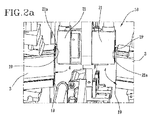
図2a、図2bおよび図2cは、各動作条件における図1aおよび図1b中の装置の詳細を示す。
図3は、さらなる動作シーケンスの詳細な図をさらに示す。
図4および図5は、往復方向に近接方向に移動するステップ時のプラスチック材料製の成形要素を示す。
図6は、本発明による収容型押圧器の斜視図である。
図7は、図6の収容型押圧器の別の角度からの斜視図である。
図8、図9、図10および図11は、本発明による成形要素のヘッド先端の溶接の後続ステップの模式図である。図中、ビードを収容型区画中に収容することを可能にする図6および図7中の収容型押圧器の使用を強調表示している。
図12は、収容型押圧器の別の実施形態の横断断面図である。
Other characteristics and advantages of the present invention are derived from a comprehensive and non-limiting description of preferred but not exclusively embodiments of methods and relative apparatus for welding molded elements made of plastic material (especially PVC). It becomes clearer.
FIGS. 1a and 1b show a one-head device for welding molding elements made of plastic material (especially PVC) according to the invention (the head can be repeated on equipment that simultaneously processes four to six corners). It is a perspective view and a schematic diagram.
2a, 2b and 2c show details of the device in FIGS. 1a and 1b at each operating condition.
FIG. 3 further shows a detailed view of a further operation sequence.
4 and 5 show the molding element made of plastic material during the step of moving in the proximity direction in the reciprocating direction.
FIG. 6 is a perspective view of a housed press according to the present invention.
FIG. 7 is a perspective view from another angle of the housed press of FIG.
8, 9, 10 and 11 are schematic views of the subsequent steps of the welding of the head tip of the forming element according to the invention. In the figure, the use of the housed pusher in FIGS. 6 and 7 which allows the bead to be housed in the housed compartment is highlighted.
FIG. 12 is a cross-sectional view of another embodiment of a housed press.
特に添付の図を参照して、参照符号1によって図示しているのは、プラスチック材料(特にPVC)製の成形要素を溶接する装置である。 Illustrated by reference numeral 1 in particular with reference to the accompanying figures, is an apparatus for welding molded elements made of plastic material (especially PVC).
このような装置は、プラスチック材料(特にPVC)製の成形要素を溶接する方法を実行する。ここで、少なくとも2つの成形要素3が配置され、それぞれの溶接対象ゾーン4が相互に対向している。
Such an apparatus implements a method for welding molded elements made of plastic material (especially PVC). Here, at least two forming
本方法に従って以下に詳細に述べるように、溝部19は、除去動作(フライス加工、溶融、面取りなど)により、成形要素3の各溶接対象ゾーン4に対応して構成される。
As will be described in detail below in accordance with this method, the
その後、成形要素3を相互に押圧して溶接対象ゾーン4を往復方向に接触保持させることにより、溶接対象ゾーン4を加熱および連結する。このようにして、2つの成形要素3の溝部19は、各成形要素3の溶融時において生成されたビードまたは溶接ビードを収容する収容型区画19aを規定する。
Then, the welding object zone 4 is heated and connected by pressing the shaping | molding
本記載の残りにおいて、2つの各成形要素の先端の溶接に適した単一の溶接装置1を例示する。それにもかかわらず、本発明は、一連の装置1を含み得る。これらの装置1はそれぞれ、成形要素3の各先端上において動作する。例えば、ドアまたは窓フレームとして用いられる矩形フレームを作製するために、4つの装置1が用いられ、装置1はそれぞれ、上記フレームの直角に対応して成形要素3を溶接することを意図する。
In the remainder of this description, a single welding device 1 suitable for welding the tips of each of the two forming elements is illustrated. Nevertheless, the present invention may include a series of devices 1. Each of these devices 1 operates on each tip of the forming
図1を参照して、装置1は、成形要素3そのものを対応する相互に対向する溶接対象ゾーン4と係合させるのに適したPVC製の各成形要素3の一対の保持部材2を含む。点に留意されたい。
With reference to FIG. 1, the device 1 includes a pair of holding
詳細には、各保持部材2は、成形要素3が載置されたベース部位5と、ベース部位5の上方に配置されたモバイル部位6とを含む。モバイル部位6は、ベース部位5に向かって適切に移動されるため、成形要素3を保持する。
Specifically, each
添付の例示から分かるように、各成形要素3はベース部位5とモバイル部位6との間に配置され、各ヘッド先端が突出している。成形要素のヘッド先端により溶接対象ゾーン4が構成されているため、相互に対向している。
As can be seen from the attached examples, each
溶接対象ゾーン4が適切に45°で切断されているため、2つの直角成形要素が連結された状態となる点に留意されたい。 Note that because the zone to be welded 4 is properly cut at 45 °, the two right-angle forming elements are connected.
さらに、装置1は、第1の往復方向の遠位位置と、溶接対象ゾーン4が共に連結される第2の往復方向の近位位置との間で成形要素3を移動させるための保持部材2の移動手段7を含む。
Furthermore, the device 1 comprises a
詳細には、各保持部材2に対し、移動手段7は、成形要素3の長手方向延長に対して平行に延びるスライドガイド8を有する。スライドガイド上には、上記ベース部位5と一体化されたカートリッジ9が取り付けられる。さらに、各カートリッジ9は、保持部材2のカートリッジ9双方を往復方向に近位/遠位へ移動させるのに適した移動システム10と連結される。
Specifically, for each
また、装置1は、PVC製の成形要素3の上記の溶接対象ゾーン4を加熱する加熱手段11を含む。加熱手段11は好適には、加熱手段11が成形要素3間に配置される活性状態と、加熱手段11が成形要素3から離隔方向に移動する非使用状態との間でとの間で移動可能である。
Moreover, the apparatus 1 includes a heating means 11 for heating the welding object zone 4 of the
詳細には、成形要素3が移動手段7により往復方向に離隔移動方向において配置された場合、成形要素3は、通過ゾーンof加熱手段11点に留意されたい。このようにして、溶接対象ゾーン4が加熱されると、成形要素3は相互に近位方向に移動し、各先端ヘッドにより相互に押圧される。
Specifically, when the forming
有利なことに、加熱手段11は、例えば移動要素13上に取り付けられた実質的にプレート形状の電気抵抗によって構成されたホットプレートヒートシール要素12を含む。好適には、移動要素13は、各レール15内にスライドして取り付けられた一対のカートリッジ14により構成される。レール15はそれぞれ、上記抵抗12の対向する側部上に配置される。このようにして、抵抗12は、カートリッジ14へ締結され、レール15に沿ってこれらによって移動させられる。カートリッジ14はまた、接続ロッドクランク17によってモータ16へ動作可能に接続される。有利なことに、接続ロッドクランク17により、モータ16からの回転移動がカートリッジ14および抵抗12の前後移動へと変換されて、電気抵抗12が上記した成形要素3間に取り付けられる/上記した成形要素3から除去される。装置1はまた、少なくとも1つの溶接対象ゾーン4の周辺縁部上に少なくとも1つの溝部19を構成する除去手段18を備える。
Advantageously, the heating means 11 comprises a hot plate
除去手段18は、例えばフライス加工型であり、保持部材2の上方に配置された支持フレーム20と、少なくとも機械加工ツール21とを含む。機械加工ツール21は、溶接対象ゾーン4上に上記した溝部19を構成する成形要素3と対向する。
The removing means 18 is, for example, a milling mold, and includes a
ツール21は、モータ部22により回転移動させられる。モータ部22は、好適には電気型であり、回転速度が極めて高速の小型のブラシレスセンサーレスモータである。さらに、ツール21は、第1のアイドル状態(ツール21が成形要素3間において配置されていない位置)と、ツール21がPVC製の成形要素3間に配置される第2の作動状態との間で移動させられる。
The
より詳細には、フライス加工を用いた除去手段18は好適にはは、一対の機械加工ツール21を含む。機械加工ツール21はそれぞれ、各溶接対象ゾーン4の周辺縁部上の活性ヘッド21aを備える。
More particularly, the removal means 18 using milling preferably includes a pair of
詳細な図に示すように、ツール21は、相互に対向して、成形要素3双方において同時に機械加工を行う。
As shown in the detailed figures, the
換言すれば、2つのツール21は、支持フレーム20の対向する側部上の同一回転軸周囲において回転する。このようにして、支持フレーム20の移動により、溶接対象ゾーン4上において作動するツール21および別の溶接対象ゾーン4上に作動する他方のツール21の前方移動の制御が可能になる。
In other words, the two
各ツール21によって得られる溝部19は、溶接対象ゾーン4の全体延長に沿って延びる、実質的に段付きの四角形形状を有する(すなわち、90°で形状される)。
The
溝部19をこのように沿って構成することにより規定される収容型区画19aは、ベース壁部60および一対の対向する側壁61によって区切られる。
The accommodation-
ベース壁部60は実質的に水平であり、側壁61は実質的に垂直である。
The
さらに、フレーム20は、支持バー24を有する。支持バー24は、保持部材2の上方に配置され、ツール21を支持するように設計される。ツール21は、この状況において、バー24そのものの下側先端上に取り付けられる。
Further, the
バー24は、溶接対象ゾーン4に対応して移動する移動部材23へ動作可能に接続される。
The
有利なことに、ツール21は、上記した移動部材23の移動により溶接対象ゾーン4の側縁部に対応して配置される。
Advantageously, the
詳細には、部材23は、バー24がスライドして上部に取り付けられかつ公知の詳述しないモータによって移動させられない一対の支持ガイド25を含む。さらに、バー24isは、フレーム20に対応して配置されたワームスクリュー26と共に軸により垂直方向に移動させられる。
Specifically, the member 23 includes a pair of support guides 25 on which the
有利なことに、ツール21およびモータ部22はどちらとも、バー24によって支持され、また、(ガイド25に沿った)水平方向および(ワームスクリュー26により)垂直方向双方に移動可能である。
Advantageously, both the
装置1はまた、ツール21と同心の渦吸引システム29aおよび29bを有する。ツール21により、フライス加工による除去動作時に発生する削りくずの除去が可能になる。
The device 1 also has
吸引システム29aおよび29bは、例えばチャンバ29aからなる。チャンバ29aは、各ツール21の周囲に配置され、削りくずを離隔方向に移動させる吸引ダクト29bへ接続される。
The
この目的のため、さらに、ツール21は、除去された削りくずをチャンバ29aの内側へ搬送して削りくずの吸引を容易にするらせん状のカッターからなる。
For this purpose, the
有利なことに、フライス加工によって除去動作により発生したプラスチック材料中の全削りくずが容易に吸引される。 Advantageously, all shavings in the plastic material generated by the removal operation by milling are easily sucked.
装置1はまた、溝部19上に隣接して溝部そのものと協働して収容型区画19aを規定するのに適した押圧手段27および28を有する。
The device 1 also has pressing
押圧手段27および28は、実際、ベース壁部60に対向しかつ側壁61に隣接する収容型区画19aの側部の近隣にあり、これにより、区画そのものからの溶融材料の流出を回避する。
The pressing means 27 and 28 are in fact near the side of the
押圧手段27および28は、詳細には、
少なくとも突出部位63を有する第1のワーク表面62と、
−少なくとも最終仕上げの第2のワーク表面64と、
を含む。
The pressing means 27 and 28 are described in detail below.
A
At least a
including.
押圧手段27および28は、動作手段65および66と協働する。押圧手段27および28は、
成形要素3から離隔方向に移動するアイドル位置
第1のワーク位置であって、溝部19上に隣接する第1のワーク表面62は、収容型区画19aの内側に少なくとも部分的に配置された突出部位63と共に、溶接ビードを収容型区画19aの側壁61に向かって逸脱させる、第1のワーク位置と、
第2のワーク位置であって、第2のワーク表面64は、仕上げ後の溶接ビードが得られるように溝部19上に隣接する、第2のワーク位置と、
の間で押圧手段27および28を交互に変位させるのに適している。
The pressing means 27 and 28 cooperate with the operating means 65 and 66. The pressing means 27 and 28 are
An idle position that moves away from the forming element 3 A first work position that is a first work position and that is adjacent to the
A second workpiece position, wherein the
It is suitable for alternately displacing the pressing means 27 and 28.
押圧手段27および28は、第1のワーク表面62および第2のワーク表面64双方を有する収容型押圧器27および28を少なくとも含む。
The pressing means 27 and 28 include at least the
しかし、第1のワーク表面62および第2のワーク表面64が相互に別個であり別個に可動であるコンポーネント上に取り付けられた別の実施形態は除外されない。
However, other embodiments in which the
例示に示す装置1の実施形態において、押圧手段27および28は、成形要素3が載置された面に対して対向する側部(上方および下方)上に対向する一対の収容型押圧器27および28を含む。
In the illustrated embodiment of the device 1, the pressing means 27 and 28 comprise a pair of housed presses 27 facing on the sides (upper and lower) facing the surface on which the
詳細には、第1の収容型押圧器27は、成形要素3の上方に配置され、本明細書中以下において上側収容型押圧器と呼ばれ援用するる。第2の収容型押圧器28は、成形要素3の下側に配置され、本明細書中以下において下側収容型押圧器と呼ばれ得る。
In detail, the 1st
収容型押圧器27および28はどちらとも、往復方向の近接する移動方向において可動であり、これにより、溝部19と協働して、区画そのものから出てくる材料を制約および限定するように、成形要素3の対向する側部上に得られた2つの収容型区画19aを規定する。実際、溝部19は、成形要素3の外部の視認可能な部位(すなわち、45°で切断された面の上側および下側縁部)のために付与される点に留意されたい。これらの部位は、相互に溶接されると、突出する溶接ビードの形成を決定する。
Both housed
この状況において、ビードは、収容型区画19aから出てこず、内部に収容される。
In this situation, the bead does not come out of the
各収容型押圧器27および28は、溝部19と実質的に平行な長手方向Aに沿って延びるロッド68を含む。
Each housed
詳細には、長手方向は実質的に水平である。 Specifically, the longitudinal direction is substantially horizontal.
ロッド68は剛性であり、例えばスチール製である。
The
各収容型押圧器27および28について、ロッド68は、第1の長手方向面69および第2の長手方向面70を含む。第1の長手方向面69に対応して、第1のワーク表面62が配置される。第2の長手方向面70に対応して、第2のワーク表面64が配置される。
For each housed
第1の長手方向面69および第2の長手方向面70は、実質的に対向しており、相互に平行である。
The first
第1のワーク表面62は、例えば接着によって第1の長手方向面69と関連付けることが可能なインサート71によって規定される。
The
インサート71は剛性であり、例えば硬質プラスチック製である。
The
第1のワーク表面62は、平坦部位72を有する。この平坦部位72から、突出部位63が延びる。
The
突出部位63は、ロッド68の実質的全体に沿って長手方向に延びる。
The protruding
その代わりに、横断部において、突出部位63は、一対の空洞73を有する。空洞73は、第1のワーク位置において、実質的に収容型区画19aの側壁61に対向して配置される。
Instead, at the cross section, the protruding
換言すれば、空洞73の存在により、突出部位63の横断面が切断される。
In other words, the cross section of the protruding
より詳細には、突出部位63は、突出するより長尺のベースを有する二等辺台形のような形状に実質的にされた横断面を有する。
More specifically, the protruding
この点において、本記載の範囲内において、「突出するより長尺のベース」という表現は、台形のより小量のベースが平坦部位72に対応して規定され、台形の二等辺が平坦部位72から突出して延び、台形のより長尺のベースの下側に延びるため、ベースは平坦部位72に対して遠位位置に配置されることが強調される。
In this regard, within the scope of the present description, the expression “longer projecting base” is defined by a smaller amount of base of the trapezoid corresponding to the
本実施形態において、突出部位63の横断面の空洞73は、台形の二等辺と平坦部位72との間に規定される。
In the present embodiment, the
しかし、突出部位の横断面が異なる形態を有する別の実施形態は除外されない。 However, another embodiment in which the cross section of the protruding portion has a different form is not excluded.
図12は、例えば、突出部位63の横断面が実質的に矩形である実施形態を示す。
FIG. 12 shows an embodiment in which, for example, the cross section of the protruding
第2のワーク表面64は、溝部19上の隣接に適したシート状要素74と、シート状要素74を支持する衝撃吸収要素75とにより、規定される。
The
シート状要素74は、例えば、肉薄または可撓性の硬質プラスチックの金属ブレードからなる。
The sheet-
一方、衝撃吸収要素75は、第2の長手方向面70とシート状要素74との間に配置されたゴムなどの降伏材料製の層である。
On the other hand, the
例示中に示す実施形態において、第2のワーク表面64は実質的に平坦であり、実質的に平坦仕上げ後の溶接ビードを得ることが可能になる。
In the illustrated embodiment, the
しかし、別の実施形態は、加工されたばかりの高温ピースを特定形状にするための突出および/または凹部第2のワーク表面64がを有する別の実施形態は除外されない。高温のままである材料は、実際に容易に成形することができる。
However, other embodiments do not exclude other embodiments having a protruding and / or recessed
また、スポーク付きの視認可能な表面を有する成形要素3の存在において、第1のワーク表面62および第2のワーク表面64は、視認可能な表面の形状に追随するような形状にされることも容易に理解される。
Further, in the presence of the
この点について、有用なことに、収容型押圧器27および28を装置1の残りから解放し、溶接すべき成形要素3の種類に応じて、形状が変化した収容型押圧器27および28と交換することが可能であることが強調される。
In this regard, it is useful to release the housed
操作手段65および66は、成形要素3の移動方向を横断する方向Bに沿って押圧手段27および28を移動させる移動ユニット65を少なくとも含む。
The operating means 65 and 66 include at least a moving
横断方向Bは、成形要素3が載置された面に対して実質的に直角であるため、垂直である。
The transverse direction B is vertical because it is substantially perpendicular to the surface on which the forming
図1aおよび図1bは、上側収容型押圧器27を平行移動させるための移動ユニット65のみを詳細に示す。
FIGS. 1 a and 1 b show in detail only the moving
このような移動ユニット65は、支持要素76が取り付けられたモバイル先端を有する垂直空気圧シリンダーにより規定される。
Such a moving
しかし、移動ユニット65の別の実施形態も可能である。
However, other embodiments of the
操作手段65および66は、少なくとも回転ユニット66も含む。回転ユニット66は、収容型押圧器27および28のロッド68を長手方向Aの周囲において回転させ、第1のワーク表面62および第2のワーク表面64を溝部19へ向かって交互に回転させるのに適している。
The operating means 65 and 66 also include at least a rotating unit 66. The rotation unit 66 rotates the
第1のワーク表面62および第2のワーク表面64がロッド68の対向する面上に取り付けられていることを考えると、回転ユニット66は、ロッド68を回転ユニット66自身の周囲において180°だけ回転させるのに適している。
Considering that the
しかし、ワーク表面62および64がロッド68の隣接および連続する面上に配置され、ロッド68の回転がちょうど90°まで低下する別の実施形態は排除されない。
However, another embodiment in which the work surfaces 62 and 64 are disposed on adjacent and continuous surfaces of the
図1aおよび図1bは、上側収容型押圧器27の回転のための回転ユニット66のみの詳細を示す。
FIGS. 1 a and 1 b show details of only the rotation unit 66 for rotation of the upper housed
このような回転ユニット66は、支持要素76とロッド68のグリップ先端77との間に配置された回転モータによって規定される。
Such a rotation unit 66 is defined by a rotation motor arranged between the
しかし、アクチュエータシリンダーおよびレバーによるクランク機構からなる場合に回転ユニット66の別の実施形態が可能である。 However, another embodiment of the rotation unit 66 is possible when it consists of a crank mechanism with an actuator cylinder and lever.
上記した装置1は、広範に構造的な意味において、本発明の対象である溶接方法を実行する。 The device 1 described above carries out the welding method which is the subject of the present invention in a broad structural sense.
この方法は、相互に対向する各溶接対象ゾーン4と共に保持部材2に対応して配置される少なくとも2つの成形要素3を作製するステップを含む。
This method comprises the step of producing at least two forming
その後、溝部19は、成形要素3の各溶接対象ゾーン4に対応して構成される。
Then, the
溝部19を作製するステップは、各成形要素3のヘッド先端によって規定された周辺縁部上の材料の除去動作により、行われる。
The step of producing the
この除去は、ツール21を用いてフライス加工により行われる。
This removal is performed by milling using the
除去ステップ時において、らせん形状のツール21と、除去された削りくずをチャンバ29a内に搬送する軸方向吸引とにより、保持ステップが行われる。
During the removal step, the holding step is performed by the
その後、溶接対象ゾーン4をホットプレートヒートシール要素12の対向する側部上に押圧し、成形要素3を相互に押圧することにより連結することにより、溶接対象ゾーン4を加熱する。溶接対象ゾーン4の連結を往復方向の接触を保持しつつ行うことにより、溶接対象ゾーン4を共に溶解させ、溶接ビードを規定する。
Then, the welding object zone 4 is heated by pressing the welding object zone 4 on the opposite side part of the hot plate heat-
溶接対象ゾーン4の連結時において、押圧手段27および28溝部19に対応して配置することからなるサブステップを行って、溝部そのものと協働して、溶接ビードの収容型区画19aを規定する。
When the welding target zone 4 is connected, a sub-step consisting of arrangement corresponding to the pressing means 27 and the 28
このようなサブステップは、押圧手段27および28をアイドル位置、第1のワーク位置および第2のワーク位置間において交互に移動させる操作手段65および66により行われる。 Such a sub-step is performed by operating means 65 and 66 that alternately move the pressing means 27 and 28 between the idle position, the first work position, and the second work position.
このようなサブステップにおいて、収容型押圧器27および28双方は、動作し、対向する側部上において成形要素3の上方および下方において動作および配置される。
In such sub-steps, both housed
図8〜図11は、上側収容型押圧器27のみの動作を示すが、下側収容型押圧器28の場合も容易に理解される。
Although FIGS. 8-11 shows operation | movement of only the upper
溶接対象ゾーン4が相互に近接して配置されると、収容型押圧器27および28は、押圧手段を横断方向Bに沿って移動させる移動ユニット65の動作により、アイドル位置から第1のワーク位置へ移動する。
When the welding object zone 4 is arranged close to each other, the housed presses 27 and 28 are moved from the idle position to the first work position by the operation of the moving
このようにして、各収容型押圧器27および28の第1のワーク表面62は、溝部19と共に、相対的な収容型区画19a(図8)の内側の突出部位63と隣接する。
In this way, the
成形要素3の相対的に近接する移動によって得られる溶接ビードは、突出部位63と接触するまで、収容型区画19aの中心において隆起し、その結果、空洞73が充填される(図9)まで、側壁61に向かって逸脱する。
The weld bead obtained by the relatively close movement of the forming
突出部位63の存在は、溶接ビードを形成する溶融プラスチック材料を収容型区画19a全体に完全かつ正確に充填する目的のために、重要である。
The presence of the protruding
この点について、突出部位63が無い場合、溶接ビードは、収容型区画19aの中心に留まり、材料が固化し始めたときにずっと後に側壁61に到達する傾向となり、これにより、常に最適にとは限らずまたいずれかの場合において非機能的な様態の収容型区画19aの充填が決定されることが強調される。
In this regard, in the absence of the protruding
その後、収容型押圧器27および28は、横断方向Bに沿って成形要素3から離隔方向に除去される。
Thereafter, the housed presses 27 and 28 are removed away from the forming
突出部位63の台形形状によって規定される切断により、空洞73を今まで占拠していた(未だに柔軟な状態であるため容易に変形可能である)プラスチック材料の記2つのリップ78の若干の上昇が決定される(図10)。
Due to the cut defined by the trapezoidal shape of the protruding
この時点において、収容型押圧器27および28が移動し、長手方向Aの周囲を回転させられて、第2のワーク表面64を第1のワーク表面62ではなく溝部19に向かって回転させ、第2のワーク位置に配置されるまで、成形要素3に近接する方向に移動させる。
At this time, the accommodating presses 27 and 28 are moved and rotated around the longitudinal direction A to rotate the
この位置において、シート状要素74は、事前に上昇していたリップ78を下方に押圧して平坦にし、溶接ビードにより任意の外方の突出を曲線状にする。
In this position, the sheet-
実際、このステップにおいて、成形要素3の溶接対象ゾーン4は、近接する方向に移動し続け、収容型区画19aが完全に充填されかつリップ78が並ぶ(図11)まで、溶融プラスチック材料は形成し続ける。
In fact, in this step, the zone 4 to be welded of the forming
図8〜図11に示すサブステップは全て、収容型区画19aが完全に充填される前に溶融材料の固化が発生することの無いような時間以内に迅速に行われる。
All the sub-steps shown in FIGS. 8 to 11 are carried out rapidly within a time such that no solidification of the molten material occurs before the
この点について、第2のワーク位置において、衝撃吸収要素75の存在により、動作時に溝部19中に発生する内圧を収容型区画19a全体に沿って均等かつ均質な様態で分散させることが可能になることが強調される。
In this regard, at the second work position, the presence of the
本発明は、提案される目的を達成する。 The present invention achieves the proposed objective.
詳細には、2つの溝部によって規定される収容型区画内に溶接ビードを維持できることにより、余分な材料の流出が回避される。 Specifically, the ability to maintain the weld bead within the containment compartment defined by the two grooves avoids excess material spillage.
その結果、余分な材料を除去するための表面仕上げ作業が全て不要になるため、さらなる機器の仕様に関連して、時間、エネルギーおよび節減において有利になる。この点に加えて、突出部位を備える第1のワーク表面および最終仕上げの第2のワーク表面による交互の干渉により、成形要素の最終的結果が美観的に優れたものになり、公知のいかなる種類の溶接方法および装置の場合よりもずっと優れたものとなる。
As a result, all surface finishing operations to remove excess material are not required, which is advantageous in terms of time, energy and savings with respect to additional equipment specifications. In addition to this point, the alternating interference between the first workpiece surface with the protruding portion and the second workpiece surface in the final finish makes the final result of the molding element aesthetically superior and any known type This is much better than the welding method and apparatus.
Claims (18)
相互に対向する各溶接対象ゾーン(4)と共に配置されたプラスチック材料製の少なくとも2つの成形要素(3)を作製するステップと、
前記溶接対象ゾーン(4)を加熱するステップと、
前記成形要素(3)を相互に押圧して溶接対象ゾーン(4)を接触した状態で保持することにより、前記溶接対象ゾーン(4)を相互に連結するステップと、
を含み、
前記前記溶接対象ゾーン(4)を連結するステップは、前記溶接対象ゾーン(4)を相互に溶融させて溶接ビードを規定するサブステップを規定し、
前記加熱ステップの前に前記溶接対象ゾーン(4)それぞれの周辺縁部に対応して溝部(19)を作製するステップを含む点において特徴付けられ、前記溶接対象ゾーン(4)を連結するステップは、
前記溝部(19)に対応して押圧手段(27、28)を配置して、前記溝部(19)と協働して、少なくとも前記溶接ビードの収容型区画(19a)を規定するサブステップであって、前記押圧手段(27、28)は、
少なくとも突出部位(63)を有する第1のワーク表面(62)、および少なくとも最終仕上げの第2のワーク表面(64)を含む、サブステップと、
前記成形要素(3)から離隔方向に移動したアイドル位置と、
前記第1のワーク表面(62)が前記溝部(19)上に隣接した第1のワーク位置であって、前記第1のワーク位置において、前記突出部位(63)が少なくとも前記収容型区画(19a)の内側に部分的に配置されて前記溶接ビードを前記収容型区画(19a)の前記側壁(61)に向かって逸脱させる、第1のワーク位置と、
仕上げ後の溶接ビードが得られるように前記第2のワーク表面(64)が前記溝部(19)上に隣接する第2のワーク位置と、
の間において交互に前記押圧手段(27、28)を変位させるサブステップと、
を含む、方法。 A method of welding the molded elements of plastic materials made,
Producing at least two molding elements (3) made of plastic material arranged with each welding zone (4) facing each other;
Heating the zone to be welded (4);
A step wherein by holding the molding element (3) is pressed to each other while touch contact the welded zone (4), interconnecting the welded zone (4),
Including
The step of connecting the weld target zones (4) defines a sub-step of melting the weld target zones (4) to define a weld bead;
Before the heating step, characterized in that it includes the step of creating a groove (19) corresponding to the peripheral edge of each of the zones to be welded (4), the step of connecting the zones to be welded (4) comprising: ,
The pressing means (27, 28) are arranged corresponding to the groove portion (19), and cooperate with the groove portion (19) to define at least the accommodating type section (19a) of the weld bead. The pressing means (27, 28)
A sub-step comprising at least a first workpiece surface (62) having a protruding portion (63) and at least a final workpiece second workpiece surface (64);
An idle position moved away from the forming element (3);
The first work surface (62) is a first work position adjacent to the groove (19), and at the first work position, the projecting part (63) is at least the storage section (19a). A first work position that is partially disposed inside the housing bead and deviates toward the side wall (61) of the containment section (19a);
A second workpiece position where the second workpiece surface (64) is adjacent to the groove (19) so as to obtain a finished weld bead;
A sub-step of displacing the pressing means (27, 28) alternately between
Including a method.
前記成形要素(3)を対向する対応する溶接対象ゾーン(4)と係合させるプラスチック材料製の各成形要素(3)の一対の保持部材(2)と、
活性状態と非使用状態との間で移動する前記成形要素(3)の前記溶接対象ゾーン(4)の加熱手段(11)であって、前記活性状態において、前記加熱手段(11)は前記成形要素(3)間に配置され、前記非使用状態において、前記加熱手段(11)は前記成形要素(3)から離隔方向に移動される、加熱手段(11)と、
前記成形要素(3)を第1の離隔移動位置と第2の近接移動位置との間で変位させる前記保持部材(2)の移動手段(7)であって、前記第2の近接移動位置において、前記溶接対象ゾーン(4)は相互に連結される、移動手段(7)と、
を含み、
前記溶接対象ゾーン(4)それぞれの周辺縁部上に少なくとも溝部(19)を作製する除去手段(18)と、
前記溝部(19)上に、前記溝部(19)と協働して、溶接ビードの収容型区画(19a)を規定する押圧手段(27、28)と、
を含み、前記押圧手段(27、28)は、
少なくとも突出部位(63)を有する第1のワーク表面(62)、および少なくとも最終仕上げの第2のワーク表面(64)と、
動作手段(65、66)であって、
前記成形要素(3)から離隔方向に移動したアイドル位置と、
前記第1のワーク表面(62)が少なくとも前記収容型区画(19a)の内側に部分的に配置された前記突出部位(63)と共に前記溝部(19)上に隣接して、前記収容型区画(19a)の前記側壁(61)に向かって前記溶接ビードを逸脱させる第1のワーク位置と、
仕上げ後の溶接ビードが得られるように前記第2のワーク表面(64)が前記溝部(19)上に隣接する第2のワーク位置と、
の間で前記押圧手段(27、28)を交互に変位させる、
動作手段(65、66)を含む点において特徴付けられる、装置(1)。 An apparatus for welding the molded elements of plastic materials manufactured by (1),
A pair of holding members (2) of each molding element (3) made of plastic material that engages the corresponding welded zone (4) facing the molding element (3);
Heating means (11) of the zone to be welded (4) of the forming element (3) moving between an active state and a non-use state, wherein in the active state, the heating means (11) Heating means (11) arranged between the elements (3), and in the non-use state, the heating means (11) is moved away from the molding element (3);
Wherein a moving means of the holding member to displace between the molding element (3) and the first release septum moved position and the second proximity movement position (2) (7), the second proximity In the moving position, the welding zone (4) is connected to each other, the moving means (7);
Including
Removing means (18) for producing at least a groove (19) on the peripheral edge of each of the welding object zones (4);
On the groove (19), wherein in cooperation with the groove (19), and housed compartment of the weld bead the pressing means you define the (19a) (27, 28),
The pressing means (27, 28) includes:
A first workpiece surface (62) having at least a protruding portion (63), and at least a final workpiece second workpiece surface (64);
Operating means (65, 66),
An idle position moved away from the forming element (3);
The first work surface (62) is adjacent to the groove (19) together with the projecting portion (63) disposed at least partially inside the housing type section (19a), and the housing type section ( A first workpiece position that deviates the weld bead towards the side wall (61) of 19a);
A second workpiece position where the second workpiece surface (64) is adjacent to the groove (19) so as to obtain a finished weld bead;
The pressing means (27, 28) are alternately displaced between
Device (1) characterized in that it comprises operating means (65, 66).
Applications Claiming Priority (3)
| Application Number | Priority Date | Filing Date | Title |
|---|---|---|---|
| ITMO2013A000024 | 2013-02-05 | ||
| IT000024A ITMO20130024A1 (en) | 2013-02-05 | 2013-02-05 | METHOD AND DEVICE FOR WELDING PROFILES IN PLASTIC MATERIAL, IN PARTICULAR PVC |
| PCT/IB2014/058769 WO2014122572A1 (en) | 2013-02-05 | 2014-02-04 | A method for welding profiled elements made of a plastic material, in particular pvc |
Related Child Applications (1)
| Application Number | Title | Priority Date | Filing Date |
|---|---|---|---|
| JP2017069790A Division JP6431117B2 (en) | 2013-02-05 | 2017-03-31 | Method and apparatus for welding molding elements made of plastic material (especially PVC) |
Publications (2)
| Publication Number | Publication Date |
|---|---|
| JP2016504976A JP2016504976A (en) | 2016-02-18 |
| JP6309028B2 true JP6309028B2 (en) | 2018-04-11 |
Family
ID=47997673
Family Applications (2)
| Application Number | Title | Priority Date | Filing Date |
|---|---|---|---|
| JP2015555842A Active JP6309028B2 (en) | 2013-02-05 | 2014-02-04 | Method and apparatus for welding molding elements made of plastic material (especially PVC) |
| JP2017069790A Active JP6431117B2 (en) | 2013-02-05 | 2017-03-31 | Method and apparatus for welding molding elements made of plastic material (especially PVC) |
Family Applications After (1)
| Application Number | Title | Priority Date | Filing Date |
|---|---|---|---|
| JP2017069790A Active JP6431117B2 (en) | 2013-02-05 | 2017-03-31 | Method and apparatus for welding molding elements made of plastic material (especially PVC) |
Country Status (10)
| Country | Link |
|---|---|
| US (1) | US9364994B2 (en) |
| EP (3) | EP3132916B2 (en) |
| JP (2) | JP6309028B2 (en) |
| CN (2) | CN107009628B (en) |
| CA (1) | CA2899380C (en) |
| ES (2) | ES2628252T3 (en) |
| IT (1) | ITMO20130024A1 (en) |
| PL (2) | PL3132916T5 (en) |
| RU (1) | RU2644865C2 (en) |
| WO (1) | WO2014122572A1 (en) |
Families Citing this family (20)
| Publication number | Priority date | Publication date | Assignee | Title |
|---|---|---|---|---|
| ES2712057T3 (en) * | 2012-03-07 | 2019-05-09 | Graf Synergy Srl | Device for welding profiled elements in plastic material, in particular PVC |
| ITMO20130024A1 (en) | 2013-02-05 | 2014-08-06 | Graf Synergy Srl | METHOD AND DEVICE FOR WELDING PROFILES IN PLASTIC MATERIAL, IN PARTICULAR PVC |
| DE102016104806A1 (en) * | 2015-03-24 | 2016-11-24 | Urban Gmbh & Co. Maschinenbau Kg | Method for connecting profile pieces |
| ITUB20152125A1 (en) | 2015-07-13 | 2017-01-13 | Graf Synergy Srl | MACHINE FOR WELDING OF PLASTIC PROFILES |
| DE102015013439B4 (en) * | 2015-10-15 | 2022-10-13 | Stürtz Maschinenbau GmbH | Process and device for welding profile bars made of plastic |
| ITUB20155075A1 (en) * | 2015-10-27 | 2017-04-27 | Graf Synergy Srl | PROCEDURE AND PLANT FOR MANUFACTURING OF WINDOWS |
| ES2961340T3 (en) * | 2016-03-15 | 2024-03-11 | Rotox Holding Gmbh & Co Kg | Device and method for joining profile parts |
| IT201600071193A1 (en) * | 2016-07-07 | 2018-01-07 | Graf Synergy Srl | MACHINE FOR WELDING OF PLASTIC PROFILES |
| DE102016114106A1 (en) * | 2016-07-29 | 2018-02-01 | Urban Gmbh & Co. Maschinenbau Kg | Method for welding profile bars |
| FR3055918B1 (en) * | 2016-09-12 | 2018-09-28 | Bruno Hassan Moini Cyrus | PROCESS FOR OBTAINING A CARPENTRY FRAME AND OPTIMIZED WELD CORK CORP. |
| IT201700056007A1 (en) * | 2017-05-23 | 2018-11-23 | Graf Synergy Srl | PROFILE WELDING MACHINE |
| DE102017127483A1 (en) | 2017-11-21 | 2019-05-23 | Rotox Besitz-Und Verwaltungsgesellschaft Mbh | Device and method for joining profile parts |
| BE1026099B1 (en) * | 2018-03-16 | 2019-10-14 | Kreafin Group Sa | PANEL OF WHICH THE COUPLING DEVICES ARE SUITABLE FOR CONNECTING THE LONG SIDE AND / OR KOPSE SIDE TOGETHER |
| DE102019109294B4 (en) * | 2019-04-09 | 2022-07-07 | Stürtz Maschinenbau GmbH | Process for welding profile bars |
| RU2720371C1 (en) * | 2019-10-09 | 2020-04-29 | Владимир Никитич Встовский | Welding head device and method of producing plastic windows |
| IT202000000856A1 (en) * | 2020-01-17 | 2021-07-17 | Graf Synergy Srl | MACHINE FOR WELDING PROFILES IN PLASTIC MATERIAL |
| IT202000000889A1 (en) * | 2020-01-17 | 2021-07-17 | Graf Synergy Srl | MACHINE FOR WELDING PROFILES IN PLASTIC MATERIAL |
| CN111408875B (en) * | 2020-04-13 | 2021-11-26 | 上海银汀创新不锈钢发展有限公司 | Seamless welding equipment for producing high-grade door leaves |
| CN111605216B (en) * | 2020-06-04 | 2021-12-17 | 江苏志纤复能科技有限公司 | Carbon fiber automobile part machining system and machining method |
| CN114799921B (en) * | 2022-05-23 | 2024-03-08 | 肇庆新华兴实业有限公司 | Waterproof strip welding equipment capable of preventing raised burrs |
Family Cites Families (31)
| Publication number | Priority date | Publication date | Assignee | Title |
|---|---|---|---|---|
| DE2638202A1 (en) * | 1976-08-25 | 1978-03-09 | Urban Gmbh & Co Elektrotechnik | Plastics welding template, esp. for window frame corners - comprising a mould fitting onto frame members to prevent flash forming at weld |
| JPS53102385A (en) * | 1977-02-18 | 1978-09-06 | Meiji Gomu Kasei Kk | Method for forming surface of welding part in synthetic resin goods |
| GB2010171B (en) * | 1977-12-20 | 1982-08-18 | Hardigg Ind Inc | Method and apparatus for bonding thermoplastic materials |
| DE2831599A1 (en) * | 1978-07-19 | 1980-01-31 | Richard Radermacher | Appts. for dressing thermo-welded plastics mitred frames - has carriage movable relative to frame and supporting orthogonal subframes carrying dressing tools |
| DE3039733A1 (en) * | 1980-10-21 | 1982-05-19 | Gebrüder Kömmerling Kunststoffwerke GmbH, 6780 Pirmasens | Butt welding mitred thermoplastic frames - in which pressed out weld polymer fills lateral slots to keep outer surfaces clean |
| SU1393566A1 (en) * | 1985-10-08 | 1988-05-07 | Производственное Объединение "Вильнюсский Завод Топливной Аппаратуры Им.50-Летия Ссср" | Method of seam friction welding |
| DE3614673A1 (en) * | 1986-04-30 | 1987-11-05 | Urban Maschinenbau | METHOD AND DEVICE FOR PRODUCING WINDOW FRAMES OD. DGL. |
| DE3634793A1 (en) * | 1986-10-11 | 1988-04-14 | Urban Maschinenbau | METHOD FOR WELDING PLASTIC PROFILES |
| CH673432A5 (en) | 1987-09-23 | 1990-03-15 | Fischer Ag Georg | |
| DE3818397A1 (en) | 1988-05-31 | 1989-12-14 | Schueco Int Gmbh & Co | METHOD AND DEVICE FOR PRODUCING A CORNER OR T-CONNECTION BETWEEN TWO PLASTIC HOLLOW PROFILE PROFILES OF A WINDOW OR DOOR |
| JP2540218B2 (en) * | 1989-12-05 | 1996-10-02 | フクビ化学工業株式会社 | Synthetic resin window frame and manufacturing method thereof |
| DE9111119U1 (en) * | 1991-09-07 | 1991-11-14 | Kommanditgesellschaft Hassomat Maschinenbau Gmbh & Co, 2000 Hamburg, De | |
| FR2691099B1 (en) * | 1992-05-13 | 1997-07-04 | Dassault Aviat | DEVICE FOR SOLIDARIZING OBJECTS MADE OF COMPOSITE MATERIALS THROUGH SIMULTANEOUS APPLICATION OF HEAT AND PRESSURE. |
| JPH0780940A (en) * | 1993-09-13 | 1995-03-28 | Sekisui Chem Co Ltd | Fusion bonding of pipe materials |
| JPH07117134A (en) * | 1993-10-21 | 1995-05-09 | Takayoshi Iwao | Method and device for crimping plastic member |
| WO1996022875A1 (en) * | 1995-01-27 | 1996-08-01 | Andersen Corporation | Vibratory welded window and door joints, method and apparatus for manufacturing the same |
| DE19506236B4 (en) * | 1995-02-23 | 2006-06-29 | Afs Federhenn Maschinen Gmbh | Process for welding four plastic profiles |
| US5855720A (en) * | 1996-03-13 | 1999-01-05 | Johnson; Orin S. | Clamping head for use in joining plastic extrusions and method thereof |
| DE19612251C1 (en) * | 1996-03-27 | 1997-04-10 | Wegoma Maschf Gmbh | Machine feeding and clamping outer corners of plastic frame for finishing operations |
| DE29608184U1 (en) * | 1996-05-06 | 1996-08-01 | Urban Maschinenbau | Device for processing a corner connection of a window frame |
| DE19736872A1 (en) | 1997-08-25 | 1999-03-04 | Huels Troisdorf | Welding mitered thermoplastic profiles for door and window production and incorporating a stop seal |
| AT410066B (en) * | 2000-05-09 | 2003-01-27 | Lisec Peter | PROCESS FOR JOINING HOLLOW PROFILE STRIPS BY WELDING |
| CA2349795A1 (en) * | 2001-06-07 | 2002-12-07 | Stephen Field | Fenestration sealed frame, insulating glazing panels |
| US20070026191A1 (en) * | 2001-06-07 | 2007-02-01 | Stephen Field | Vibration welding element for thermoplastic members |
| GB2376656A (en) * | 2001-06-21 | 2002-12-24 | Gti Kombimatec Machines Ltd | Removing notches from the weld face areas of components, to locally reduce waste sprue produced during thermal bonding, apparatus, method & preparation |
| JP3889303B2 (en) * | 2002-03-29 | 2007-03-07 | ジー・ピー・ダイキョー株式会社 | Hollow body joint structure with internal member |
| FR2873151B1 (en) * | 2004-07-15 | 2008-06-06 | Smpa Soc Par Actions Simplifie | METHOD FOR PRODUCING A CHASSIS, ESPECIALLY WINDOW FROM PROFILES, OF A PLASTIC MATERIAL |
| US20090104399A1 (en) * | 2006-05-15 | 2009-04-23 | Stephen Field | Vibration welded joint structures, methods, and apparatus for thermoplastic members |
| US7935211B2 (en) | 2007-12-05 | 2011-05-03 | Lasusa Frank | Corner joinery system and method for PVC windows and polymeric substrates used in building products |
| EP2255942B1 (en) * | 2009-05-28 | 2013-03-20 | Murat Makina Sanayi ve Ticaret Ltd. Sti. | Profile welding and deburring method |
| ITMO20130024A1 (en) | 2013-02-05 | 2014-08-06 | Graf Synergy Srl | METHOD AND DEVICE FOR WELDING PROFILES IN PLASTIC MATERIAL, IN PARTICULAR PVC |
-
2013
- 2013-02-05 IT IT000024A patent/ITMO20130024A1/en unknown
-
2014
- 2014-02-04 PL PL16188496.0T patent/PL3132916T5/en unknown
- 2014-02-04 EP EP16188496.0A patent/EP3132916B2/en active Active
- 2014-02-04 JP JP2015555842A patent/JP6309028B2/en active Active
- 2014-02-04 US US14/765,569 patent/US9364994B2/en active Active
- 2014-02-04 RU RU2015126921A patent/RU2644865C2/en active
- 2014-02-04 CN CN201710211763.4A patent/CN107009628B/en active Active
- 2014-02-04 EP EP14706111.3A patent/EP2953782B1/en active Active
- 2014-02-04 WO PCT/IB2014/058769 patent/WO2014122572A1/en active Application Filing
- 2014-02-04 PL PL14706111T patent/PL2953782T3/en unknown
- 2014-02-04 CA CA2899380A patent/CA2899380C/en active Active
- 2014-02-04 CN CN201480017506.1A patent/CN105050797B/en active Active
- 2014-02-04 ES ES14706111.3T patent/ES2628252T3/en active Active
- 2014-02-04 ES ES16188496T patent/ES2656420T5/en active Active
- 2014-02-04 EP EP16189037.1A patent/EP3132917A1/en not_active Withdrawn
-
2017
- 2017-03-31 JP JP2017069790A patent/JP6431117B2/en active Active
Also Published As
| Publication number | Publication date |
|---|---|
| ES2628252T3 (en) | 2017-08-02 |
| EP2953782A1 (en) | 2015-12-16 |
| PL2953782T3 (en) | 2017-09-29 |
| US9364994B2 (en) | 2016-06-14 |
| EP3132917A1 (en) | 2017-02-22 |
| EP3132916A1 (en) | 2017-02-22 |
| JP2016504976A (en) | 2016-02-18 |
| PL3132916T3 (en) | 2018-04-30 |
| ES2656420T3 (en) | 2018-02-27 |
| RU2644865C2 (en) | 2018-02-14 |
| EP3132916B1 (en) | 2017-11-08 |
| CN107009628B (en) | 2020-03-24 |
| JP6431117B2 (en) | 2018-11-28 |
| ES2656420T5 (en) | 2024-02-27 |
| CA2899380A1 (en) | 2014-08-14 |
| CN105050797B (en) | 2017-04-26 |
| JP2017170900A (en) | 2017-09-28 |
| EP3132916B2 (en) | 2023-09-06 |
| CN107009628A (en) | 2017-08-04 |
| CN105050797A (en) | 2015-11-11 |
| WO2014122572A1 (en) | 2014-08-14 |
| CA2899380C (en) | 2021-05-25 |
| US20150367568A1 (en) | 2015-12-24 |
| RU2015126921A (en) | 2017-03-15 |
| PL3132916T5 (en) | 2023-11-27 |
| ITMO20130024A1 (en) | 2014-08-06 |
| EP2953782B1 (en) | 2017-04-05 |
Similar Documents
| Publication | Publication Date | Title |
|---|---|---|
| JP6431117B2 (en) | Method and apparatus for welding molding elements made of plastic material (especially PVC) | |
| US9993969B2 (en) | Device for welding profiled elements in plastic material, in particular PVC | |
| EP3117981B1 (en) | Machine for sealing plastic profiled elements | |
| KR102501218B1 (en) | Machine for welding profile elements | |
| KR101588301B1 (en) | Injection Mold of Rib Fomation Apparatus | |
| CN109476093B (en) | Machine for sealing plastic shaped elements |
Legal Events
| Date | Code | Title | Description |
|---|---|---|---|
| A621 | Written request for application examination |
Free format text: JAPANESE INTERMEDIATE CODE: A621 Effective date: 20161207 |
|
| A521 | Request for written amendment filed |
Free format text: JAPANESE INTERMEDIATE CODE: A523 Effective date: 20170331 |
|
| A131 | Notification of reasons for refusal |
Free format text: JAPANESE INTERMEDIATE CODE: A131 Effective date: 20171023 |
|
| A521 | Request for written amendment filed |
Free format text: JAPANESE INTERMEDIATE CODE: A523 Effective date: 20180122 |
|
| TRDD | Decision of grant or rejection written | ||
| A01 | Written decision to grant a patent or to grant a registration (utility model) |
Free format text: JAPANESE INTERMEDIATE CODE: A01 Effective date: 20180215 |
|
| A61 | First payment of annual fees (during grant procedure) |
Free format text: JAPANESE INTERMEDIATE CODE: A61 Effective date: 20180313 |
|
| R150 | Certificate of patent or registration of utility model |
Ref document number: 6309028 Country of ref document: JP Free format text: JAPANESE INTERMEDIATE CODE: R150 |
|
| R250 | Receipt of annual fees |
Free format text: JAPANESE INTERMEDIATE CODE: R250 |
|
| R250 | Receipt of annual fees |
Free format text: JAPANESE INTERMEDIATE CODE: R250 |
|
| R250 | Receipt of annual fees |
Free format text: JAPANESE INTERMEDIATE CODE: R250 |
|
| R250 | Receipt of annual fees |
Free format text: JAPANESE INTERMEDIATE CODE: R250 |