JP6303284B2 - Linear motor - Google Patents
Linear motor Download PDFInfo
- Publication number
- JP6303284B2 JP6303284B2 JP2013089727A JP2013089727A JP6303284B2 JP 6303284 B2 JP6303284 B2 JP 6303284B2 JP 2013089727 A JP2013089727 A JP 2013089727A JP 2013089727 A JP2013089727 A JP 2013089727A JP 6303284 B2 JP6303284 B2 JP 6303284B2
- Authority
- JP
- Japan
- Prior art keywords
- plate
- base
- magnetic pole
- stator
- teeth
- Prior art date
- Legal status (The legal status is an assumption and is not a legal conclusion. Google has not performed a legal analysis and makes no representation as to the accuracy of the status listed.)
- Active
Links
Images


Description
本発明はリニアモータに関する。 The present invention relates to linear motors.
例えば、半導体製造装置、液晶表示装置の製造分野においては、大面積の基板等の処理対象物を高速度にて直線移動させ、適宜の移動位置にて高精度に位置決めすることができる送り装置が必要である。この種の送り装置は、一般的には、駆動源としてのモータの回転運動をボールねじ機構等の運動変換機構により直線運動に変換して実現されるが、運動変換機構が介在することから、移動速度の高速化に限界がある。また運動変換機構の機械的な誤差の存在により、位置決め精度も不十分であるという問題がある。 For example, in the field of manufacturing semiconductor manufacturing devices and liquid crystal display devices, there is a feeding device that can linearly move an object to be processed such as a large-area substrate at a high speed and accurately position the object at an appropriate moving position. is necessary. This type of feeding device is generally realized by converting the rotational motion of a motor as a drive source into a linear motion by a motion conversion mechanism such as a ball screw mechanism, but since a motion conversion mechanism is interposed, There is a limit to increasing the moving speed. There is also a problem that positioning accuracy is insufficient due to the presence of mechanical errors in the motion conversion mechanism.
この問題に対応するため、近年においては、直線運動出力が直接的に取り出し可能なリニアモータを駆動源とする送り装置が使用されている。リニアモータは、直線状の固定子と該固定子に沿って移動する可動子とを備えている。前述した送り装置においては、板状の永久磁石を一定間隔毎に多数並設して固定子を構成し、磁極歯と通電コイルとを備える電機子を可動子としたムービングコイル型のリニアモータ(例えば、特許文献1参照)が使用されている。 In order to cope with this problem, in recent years, a feeding device using a linear motor capable of directly taking out a linear motion output as a drive source has been used. The linear motor includes a linear stator and a mover that moves along the stator. In the above-described feeding device, a moving coil type linear motor (a moving coil type linear motor) in which a large number of plate-like permanent magnets are arranged in parallel at regular intervals to constitute a stator, and an armature having magnetic pole teeth and energizing coils is used as a mover. For example, Patent Document 1) is used.
ムービングコイル型のリニアモータでは、固定子に磁石を配置するため、リニアモータの全長が長くなるほど(可動子の移動距離が長くなるほど)、使用する磁石の量が増える。近年、希土類の価格上昇に伴い、使用する磁石量の増加は、コスト増加の原因となっていた。このような問題を解決するために、本願発明者らはコイル及び磁石を可動子に備えたリニアモータを提案している。
一方、リニアモータにおいては、可動子及び固定子により磁束ループが構成される。可動子及び固定子を形成する磁性材料の多くは導電性の金属である。そのため、磁束の流れに伴い、渦電流が発生する。渦電流は反力の元になるため、リニアモータの推力を低減させてしまうことがあった。
In a moving coil type linear motor, since magnets are arranged on the stator, the amount of magnets to be used increases as the total length of the linear motor increases (the moving distance of the mover increases). In recent years, with the increase in the price of rare earths, an increase in the amount of magnets used has caused an increase in cost. In order to solve such a problem, the present inventors have proposed a linear motor having a coil and a magnet in a mover.
On the other hand, in a linear motor, a magnetic flux loop is constituted by a mover and a stator. Many of the magnetic materials forming the mover and the stator are conductive metals. Therefore, an eddy current is generated with the flow of magnetic flux. Since the eddy current is the source of the reaction force, the thrust of the linear motor may be reduced.
本発明は上述のごとき事情に鑑みてなされたものであり、渦電流を低減させるリニアモータを提供することを目的とする。 The present invention has been made in view of the above such circumstances, and an object thereof is to provide a linear motors to reduce the eddy currents.
本発明に係るリニアモータは、コイル内部に、それぞれ板状をなす2つの磁石及び3つのヨークが移動方向に沿って交互に配列してあり、2つの前記磁石は前記移動方向に沿って磁化してあり、磁化方向は互いに対向している可動子と、複数の磁極歯、及び該複数の磁極歯が並設してあり、並設方向に長い対向する一対の長尺部材を含む基部を有する固定子とを備えるリニアモータにおいて、各前記磁極歯は並設方向に交差し、かつ基部の対向方向に直交する方向に積層した複数の金属板を含み、前記磁石及びヨークは、前記磁極歯と対向する面が略面一となっていることを特徴とする。 In the linear motor according to the present invention, two magnets and three yokes each having a plate shape are alternately arranged in the coil along the moving direction, and the two magnets are magnetized along the moving direction. There Te has a mover magnetization direction that face each other, a plurality of magnetic pole teeth, and the magnetic pole teeth of said plurality of Yes and juxtaposed, the base including a pair of elongate members for a long face the arrangement direction In a linear motor including a stator, each of the magnetic pole teeth includes a plurality of metal plates that intersect in a parallel direction and are stacked in a direction perpendicular to the opposing direction of the base, and the magnet and the yoke include the magnetic pole teeth The opposing surfaces are substantially flush with each other.
本発明にあっては、各磁極歯は並設方向に交差し、かつ基部の対向方向に直交する方向に積層した複数の金属板を含んでいる。リニアモータの動作時に磁束は各金属板面に平行な向きに流れる。磁束の流れに伴い発生する渦電流は各金属板を貫こうとする方向に流れようとするが、金属板を積層しているため、渦電流は各金属板間を貫通して流れにくくなる。それにより、渦電流が低減し、推力の渦電流損を低減することが可能となる。 In the present invention, each of the magnetic pole teeth includes a plurality of metal plates that are stacked in a direction that intersects the juxtaposed direction and that is orthogonal to the opposing direction of the base. During operation of the linear motor, the magnetic flux flows in a direction parallel to each metal plate surface. The eddy current generated with the flow of the magnetic flux tends to flow in a direction to penetrate each metal plate. However, since the metal plates are laminated, the eddy current hardly flows through the metal plates. Thereby, the eddy current is reduced, and the eddy current loss of thrust can be reduced.
本発明に係るリニアモータは、前記金属板は積層面の少なくとも一部に絶縁処理を施してあることを特徴とする。 Linear motors according to the present invention, the metal plate is characterized in that at least a portion of the laminate surface are subjected to insulation treatment.
本発明にあっては、磁極歯を構成する金属板の積層面の少なくとも一部に絶縁処理を施してあるので、渦電流は各金属板間を貫通して流れにくくなる。それにより渦電流は低減し、渦電流損を低減することが可能になる。 In the present invention, since at least a part of the laminated surface of the metal plates constituting the magnetic pole teeth is subjected to insulation treatment, eddy currents hardly flow through the metal plates. Thereby, eddy current is reduced, and eddy current loss can be reduced.
本発明に係るリニアモータは、前記各基部は前記対向方向に積層した複数の金属板を含むことを特徴とする。 Linear motors according to the present invention, each of the base characterized in that it comprises a plurality of metal plates laminated in the opposing direction.
本発明にあっては、各基部は対向方向に積層した複数の金属板を含んでいる。リニアモータの動作時に磁束は各金属板面に平行な向きに流れる。磁束の流れに伴い発生する渦電流は各金属板を貫こうとする方向に流れようとするが、各金属板は積層してあるため、渦電流は各金属板間で流れにくくなる。それにより、渦電流が低減し、推力の渦電流損を低減することが可能となる。 In the present invention, each base includes a plurality of metal plates stacked in the facing direction. During operation of the linear motor, the magnetic flux flows in a direction parallel to each metal plate surface. The eddy current generated with the flow of the magnetic flux tends to flow in a direction to penetrate each metal plate. However, since each metal plate is laminated, the eddy current hardly flows between the metal plates. Thereby, the eddy current is reduced, and the eddy current loss of thrust can be reduced.
本発明に係るリニアモータは、前記各基部に含まれる金属板は積層面の少なくとも一部に絶縁処理を施してあることを特徴とする。 Linear motors according to the present invention, the metal plate contained in the respective base, characterized in that at least a portion of the laminate surface are subjected to insulation treatment.
本発明にあっては基部を構成する金属板は積層面の少なくとも一部に絶縁処理が施してあるので、渦電流は各金属板間を貫通して流れにくくなる。それにより、渦電流が低減し、渦電流損を低減することが可能になる。 In the present invention, since the metal plate constituting the base is subjected to insulation treatment on at least a part of the laminated surface, the eddy current hardly flows through the metal plates. Thereby, eddy current is reduced, and eddy current loss can be reduced.
本発明に係るリニアモータは、前記各基部は隣り合う2つの前記磁極歯の間を接続する接続部と、該接続部同士を結ぶ連結部とを有することを特徴とする。 Linear motors according to the present invention is characterized by having a connecting portion for connecting the two of the magnetic pole teeth each base adjacent a connecting portion connecting said connecting portions.
本発明にあっては、各基部は、隣り合う2つの磁極歯の間を接続する接続部と、当該接続部同士を結ぶ連結部とを有する。基部は磁極歯と別体としてあり、それぞれの磁束の流れる方向に金属板を積層することが可能となるので、渦電流の切断が可能となる。 In the present invention, each base has a connecting portion that connects between two adjacent magnetic pole teeth, and a connecting portion that connects the connecting portions. The base is separate from the magnetic pole teeth, and the metal plates can be stacked in the direction in which each magnetic flux flows, so that the eddy current can be cut.
本発明に係るリニアモータは、前記各磁極歯は前記基部の略延在方向に突出する鍔部を有し、前記接続部は前記鍔部を受け止める受止部を有することを特徴とする。 Linear motors according to the present invention, each magnetic pole tooth has a flange portion protruding substantially extending direction of the base portion, the connecting portion is characterized by having a receiving portion for receiving the flange portion.
本発明にあっては、各磁極歯に基部の略延在方向に突出する鍔部を設けたので、リニアモータ動作時に、固定子に吸引される磁極歯の脱落を防止することが可能となる。 In the present invention, since the hook portion protruding in the substantially extending direction of the base portion is provided on each magnetic pole tooth, it is possible to prevent the magnetic pole teeth attracted by the stator from falling off during the linear motor operation. .
本発明に係るリニアモータは、前記各基部を結合する結合部を備え、該結合部は前記磁極歯の並設方向に直交し、かつ前記対向方向に直交する方向に積層した複数の金属板を含むことを特徴とする。 Linear motors according to the present invention includes a coupling portion for coupling the respective base, the binding unit is perpendicular to the arrangement direction of the magnetic pole teeth, and a plurality of metal plates laminated in a direction orthogonal to the opposing direction It is characterized by including.
本発明にあっては、基部を結合する結合部は磁極歯の並設方向に直交し、かつ対向方向に直交する方向に積層した複数の金属板を含む。リニアモータの動作時に磁束は各金属板面に平行な方向に流れる。磁束の流れに伴い発生する渦電流は各金属板を貫こうとする方向に流れようとするが、各金属板の積層してあるため、渦電流は各金属板間を貫通して流れにくくなる。それにより、渦電流が低減し、推力の渦電流損を低減することが可能となる。 In the present invention, the coupling portion for coupling the base portion includes a plurality of metal plates stacked in a direction perpendicular to the parallel arrangement direction of the magnetic pole teeth and perpendicular to the opposing direction. During operation of the linear motor, the magnetic flux flows in a direction parallel to each metal plate surface. The eddy current generated by the flow of magnetic flux tends to flow in the direction of penetrating each metal plate, but since the metal plates are stacked, the eddy current is difficult to flow through between the metal plates. . Thereby, the eddy current is reduced, and the eddy current loss of thrust can be reduced.
本発明に係るリニアモータは、前記結合部に含まれる前記金属板は積層面の少なくとも一部に絶縁処理が施してあることを特徴とする。 Linear motors according to the present invention, the metal plate contained in the binding unit is characterized in that at least a portion of the laminate surface are insulated is subjected.
本発明にあっては金属板の少なくとも一部に絶縁処理が施してあるので、渦電流は各金属板間を貫通して流れにくくなる。それにより渦電流は低減し、渦電流損を低減することが可能になる。 In the present invention, since at least a part of the metal plate is insulated, the eddy current hardly flows through the metal plates. Thereby, eddy current is reduced, and eddy current loss can be reduced.
本発明に係るリニアモータは、前記結合部は前記複数の金属板にさらに重なる本体部を有することを特徴とする。 Linear motors according to the present invention, the coupling unit is characterized by having a main body portion further overlaps the plurality of metal plates.
本発明にあっては、結合部は積層した金属板と本体部からなるので、結合部の強度を高めることが可能となる。 In the present invention, since the coupling portion is composed of the laminated metal plate and the main body portion, the strength of the coupling portion can be increased.
本発明に係るリニアモータは、前記基部は対向する面の反対面を覆う補強部を備えることを特徴とする。 Linear motors according to the present invention, the base is characterized by having a reinforcing section which covers the opposite surface of the opposing surfaces.
本発明にあっては、前記基部は対向する面の反対面を覆う金属性の補強部を備えるので、金属板で構成されている基部の剛性を向上することが可能となる。 In the present invention, the base portion includes the metallic reinforcing portion that covers the opposite surface of the opposing surface, so that the rigidity of the base portion formed of the metal plate can be improved.
本発明に係るリニアモータは、前記補強部は前記基部の側面から前記対向する面に連なり前記基部を積層方向に押圧する押圧爪を備えることを特徴とする。 Linear motors according to the present invention, the reinforcing portion is characterized by having a pressing pawl that presses the base in the stacking direction continuous to opposing surfaces from a side of the base.
本発明にあっては、押圧爪により基部を積層方向に押圧するので、基部を構成する金属板同士が剥離することを防ぐことが可能となる。 In the present invention, since the base is pressed in the stacking direction by the pressing claw, it is possible to prevent the metal plates constituting the base from being separated from each other.
本発明に係るリニアモータは、前記各磁極歯は積層方向に貫通する空洞部を備えることを特徴とする。 Linear motors according to the present invention, each of the magnetic pole teeth is characterized by having a cavity extending through in the stacking direction.
本発明にあっては、各磁極歯は積層方向に貫通する空洞部を備えるので、各磁極歯の軽量化が可能となる。また、磁極歯の製造時、空洞部を構成する各金属板の貫通孔に治具を通すことにより、金属板を正確に位置決めし積層することが可能となる。 In the present invention, each magnetic pole tooth includes a hollow portion that penetrates in the stacking direction, so that the weight of each magnetic pole tooth can be reduced. Further, when the magnetic pole teeth are manufactured, it is possible to accurately position and stack the metal plates by passing a jig through the through holes of the respective metal plates constituting the cavity.
本発明に係るリニアモータは、前記基部の一方の磁極歯及び前記基部の他方の磁極歯は並設方向に千鳥配置としてあることを特徴とする。 Linear motors according to the present invention, the other magnetic pole teeth of one of the magnetic pole teeth and the base of said base portion is characterized in that there as a staggered arrangement direction.
本発明にあっては、磁極歯を千鳥配置としてあるので、動作時に可動子では磁束を移動方向に流すことが可能となる。それにより、固定子においては主として移動方向に交差する方向に磁束が流れるので、端効果を低減することが可能となる。 In the present invention, since the magnetic pole teeth are arranged in a staggered manner, it is possible to cause a magnetic flux to flow in the moving direction in the mover during operation. Thereby, in the stator, since the magnetic flux mainly flows in a direction intersecting the moving direction, the end effect can be reduced.
本発明に係るリニアモータは、前記磁極歯は直方体状をなし、前記磁極歯の前記基部に平行な面の向かい合う2つの短辺は前記基部の延在方向に対し傾斜していることを特徴とする。 Linear motors according to the present invention, the magnetic pole teeth are rectangular parallelepiped shape, the two short sides opposite the plane parallel to the base of the magnetic pole teeth and being inclined with respect to the extending direction of the base portion To do.
本発明にあっては、磁極歯が所謂、スキュー配置されているので、ディテント力が低減され、固定子と可動子の相対位置の違いによる推力むらを低減することが可能となる。 In the present invention, since the magnetic pole teeth are arranged in a so-called skew, the detent force is reduced, and it is possible to reduce thrust unevenness due to the difference in the relative positions of the stator and the mover.
本発明に係るリニアモータは、前記基部の一方が有する前記磁極歯の前記2つの短辺の傾斜方向、及び前記基部の他方が有する前記磁極歯の前記2つの短辺の傾斜方向は、互いに逆方向であることを特徴とする。 Linear motors according to the present invention, the inclination direction of the two short sides of the magnetic pole teeth inclination direction of the two short sides of the magnetic pole teeth, and the other of said base portion having the one having the base, opposite to each other It is a direction.
本発明にあっては、基部の一方が備える磁極歯と、基部の他方が有する磁極歯の傾斜方向を互いに逆方向としてあるので、可動子が移動方向に対して左右に傾くことにより生じるこじりを抑えることが可能となる。 In the present invention, since the magnetic pole teeth included in one of the base portions and the magnetic pole teeth included in the other base portion are opposite to each other, the twist caused by the mover tilting left and right with respect to the moving direction is prevented. It becomes possible to suppress.
なお、本発明において金属板の積層面の少なくとも一部に絶縁処理を施すとは、すなわち金属板の積層面の一部分に絶縁処理を施すのみならず、さらには積層面に絶縁処理を施していない金属板と絶縁処理を施した金属板を積層する場合を含む。 In the present invention, at least a part of the laminated surface of the metal plate is insulated, that is, not only a part of the laminated surface of the metal plate is insulated, but further, the laminated surface is not insulated. This includes the case where a metal plate and a metal plate subjected to insulation treatment are laminated.
本発明にあっては、各磁極歯は並設方向に直交し、かつ基部の対向方向に直交する方向に積層した複数の金属板を含んでいる。それにより、リニアモータ動作時に発生する渦電流は各金属板間を貫通して流れにくくなるので、渦電流が低減し、推力の渦電流損を低減することが可能となる。 In the present invention, each magnetic pole tooth includes a plurality of metal plates stacked in a direction orthogonal to the juxtaposed direction and orthogonal to the opposing direction of the base. As a result, the eddy current generated during the operation of the linear motor is less likely to flow through between the metal plates, so that the eddy current can be reduced and the eddy current loss of thrust can be reduced.
以下、本発明をその実施の形態を示す図面に基づき具体的に説明する。
実施の形態1
図1は実施の形態1に係る固定子1001の一例を示す斜視図である。固定子1001は第1板状部1、第2板状部2及び結合部3を含む。第1板状部1(基部)は複数の固定子歯11(磁極歯)及び当該固定子歯11が固定される第1積層板12を含み、全体として矩形板状をなす。同様に、第2板状部2(基部)は複数の固定子歯21及び当該固定子歯21(磁極歯)が固定される第2積層板22を含み、全体として矩形板状をなす。結合部3はそれぞれ矩形板状の第3積層板31及び本体部32を含む。
Hereinafter, the present invention will be specifically described with reference to the drawings showing embodiments thereof.
FIG. 1 is a perspective view showing an example of a
図2は第1積層板12の構成例を示す斜視図である。第1積層板12は第1板片121(金属板)及び第2板片122(金属板)を積層したものである。第1板片121及び第2板片122は櫛歯形薄板である。第1板片121は櫛歯の根元部分である長板部121a、長板部121aの長辺部から延びている櫛歯部121bを含む。長板部121aにはボルト挿通孔121cが設けてある。同様に第2板片122は櫛歯の根元部分である長板部122a、長辺部122aの長辺部から延びている櫛歯部122bを含む。長板部122aにはボルト挿通孔(図に現れず)が設けてある。
FIG. 2 is a perspective view illustrating a configuration example of the first
第1板片121の長板部121aと第2板片122の長板部122aとは略同一形状をなしている。第1板片121の櫛歯部121bは第2板片122の櫛歯部122bよりも細くなっている。すなわち、櫛歯部121bと櫛歯部122bとの長さは略同一寸法であるが、櫛歯部121bの幅は櫛歯部122bの短手方向の幅よりも狭くなっている。長板部121aと長板部122aとの位置を合わせて第2板片122の上に第1板片121を重ねると、第2板片122のボルト挿通孔は第1板片121のボルト挿通孔121cと連通する位置に設けられている。櫛歯部121bと櫛歯部122bとは短手方向の位置が中央合わせされ、櫛歯部121bの短手方向両脇に櫛歯部122bとの段差が形成される。
The long plate portion 121a of the
第1板片121及び第2板片122は軟磁性を有する珪素鋼の薄板により形成する。表面は絶縁物質の被膜を形成するなどの絶縁処理が施されている。図2には第1板片121が2枚、第2板片122が10枚描かれているがあくまでも一例に過ぎない。第1板片121及び第2板片122の重ねる枚数は仕様に応じて適宜設計すれば良い。また、板厚も仕様に応じて適宜設計すれば良い。板厚を薄くするほど、すなわち積層枚数が多いほど、渦電流損は低減するが、強度や組み立て時の手間を考慮すると0.2〜0.5mm程度が望ましい。
なお本発明において板片表面の絶縁処理は必ずしも必須ではない。板片を積層して板状部を作ることで、板状部表面間の隙間や、その表面に形成される酸化被膜などの影響で、電気抵抗が大きくなるため、板状部を軟磁性体のブロックで構成する場合に比べて渦電流を低減することが可能となる。
The
In the present invention, the insulation treatment on the surface of the plate piece is not necessarily essential. By laminating plate pieces to make a plate-like part, the electrical resistance increases due to the effect of the gap between the plate-like part surfaces and the oxide film formed on the surface. The eddy current can be reduced as compared with the case of the block.
第1板片121及び第2板片122は、熱溶着又はカシメにて固定される。熱溶着の場合は、例えば、第1板片121及び第2板片122の表面にペースト状の接着剤を塗布する。第1板片121及び第2板片122を重ねあわせた後に板面に圧を掛けて加熱する。加熱により接着が完了する。
また板片にあらかじめ熱溶着性の塗膜を付したものを使用してもよい。このような塗膜は絶縁被膜としての機能も有する。
The
Moreover, you may use what attached the heat-welding coating film to the board piece beforehand. Such a coating film also has a function as an insulating coating.
カシメにより固定する場合は、例えば以下のように行う。図3はカシメによる積層方法を説明するための説明図である。図3では第2板片122同士を固定する様子を示しているが、第1板片121及び第2板片122を固定する場合、第1板片121同士を固定する場合も同様である。図3Aは爪によるカシメ方法を示している。上側の第2板片122の一部に舌片122dを形成する。舌片122dは例えば平面視三角形、長方形をしている。長方形であれば短辺の一辺のみを残して、残り3辺は第2板片122から切り離した状態となっている。舌片122dは平面視同一位置に下側の第1板片121に設けてある。一番下側の第2板片122は舌片122dを切り取り、舌片122dと略同一寸法の貫通孔122fを設けている。各舌片122dは下側に折り曲げる。各舌片122dが折り曲げられることにより、形成される空間に上側の舌片122dが入り込むことにより、接している2枚の第2板片122同士が固定される。
When fixing by caulking, for example, it is performed as follows. FIG. 3 is an explanatory view for explaining a laminating method by caulking. FIG. 3 shows a state in which the
図3Bは突起部122hにより固定する方法である。一番下側の第2板片122は上述したのと同様に貫通穴122fとしている。各第2板片122をプレス成形することにより、一面に突起部122h、他面に窪み122gを設ける。第2板片122を積層する際には、下側に位置する第2板片122の窪み122gに上から重ねる第2板片122の突起部122hが入り込むことにより、接している2枚の第2板片122同士が固定される。
FIG. 3B shows a method of fixing by the
図3Cは突起部122hの断面形状がV字状とした場合である。固定する方法は図3Bの場合と同様であるので、説明を省略する。第2板片122の固定方法は上述した方法の他、リベットによる固定やレーザ溶接等でも良い。上述の説明では第1積層板12についてのみ説明したが、第2積層板22についても同様であるので、説明を省略する。なお、上述の舌片122d又は突起部122hにより第2板片122同士を固定した場合、第2板片122の板面に絶縁処理が施されている場合であっても、舌片122d又は突起部122dを加工することにより、絶縁被膜が剥がれる。そうすると、第2板片122間が電気的に導通しやすくなり、第2板片122間に渦電流が流れることとなる。第2板片間122に流れる渦電流を小さくするためには、舌片122d又は突起部122hの表面積は可能な限り小さいことが望ましい。リベットで固定する場合も電気抵抗が大きいもので、体積が小さいものが望ましい。
FIG. 3C shows a case where the cross-sectional shape of the
図4は固定子歯11、21の構成例を示す斜視図である。固定子歯11及び固定子歯21の構成は同様であるので、以下では固定子歯11のみについて説明する。固定子歯11は歯板片111(金属板)を積層して構成されている。歯板片111は矩形板形状の1つの辺縁より長手方向に突出する2つの耳部111aが設けてある薄板である。歯板片111は軟磁性の特性を持つ珪素鋼板で形成する。板厚は0.2から0.5mm程度である。歯板片111の表面は絶縁処理が施されている。歯板片111の板面中央付近には貫通孔111bが設けてある。貫通孔111bは歯板片111を複数枚積層する際に治具を通すための孔である。貫通孔111bを用いることにより、複数枚の歯板片111を精度良く位置決めをして積層することが可能となる。また、固定子歯11の軽量化にも寄与することとなる。
なお本発明において歯板片111表面の絶縁処理は必ずしも必須ではない。歯板片111を積層して固定歯11を作ることで、歯板片111表面間の隙間や、その表面に形成される酸化被膜などの影響で、電気抵抗が大きくなるため、歯板片111を軟磁性体のブロックで構成する場合に比べて渦電流を低減できる。
FIG. 4 is a perspective view showing a configuration example of the
In addition, in this invention, the insulation process of the
固定子歯11は歯板片111を複数枚積層し、熱溶着又はカシメにより固定する。熱溶着及びカシメの方法については、上述した方法と同様である。1つの固定子歯11につき、歯板片111を積層する枚数、歯板片111の板厚は仕様に応じて適宜設計すれば良い。
また板片にあらかじめ熱溶着性の塗膜を付したものでもよい。このような塗膜は絶縁被膜としての機能も有する。
The
Moreover, what attached the heat-weldable coating film beforehand to the board piece may be used. Such a coating film also has a function as an insulating coating.
図5は第1板状部1の分解斜視図である。図6は第1積層板12に固定子歯11を固定する方法を説明するための説明図である。固定子歯11は第1積層板12の櫛歯部12bの間に固定される。固定方法は軽圧入又は接着である。軽圧入の場合、第1積層板12に形成された段差部12d(受止部)に固定子歯11の耳部11aが圧入されることにより固定される。耳部11aの横幅をW1、隣り合う櫛歯部12bに形成された段差部12dの間の幅をW2とすると、W1は若干W2よりも長くしてある。固定子歯11を隣り合う櫛歯部12bの間に入れ、耳部11aを含む上面から圧力を掛けることにより、耳部11aが弾性変形し段差部12dに入り込み、固定子歯11は固定される。固定子歯11の先端は第1積層板12より突出している。
FIG. 5 is an exploded perspective view of the first plate-
固定子歯11は第1板状部1に沿って所定間隔で並設してある。同様に固定子歯21は第2板状部2に沿って所定間隔で並設してある。固定子歯11及び固定子歯21は並設方向に沿って千鳥配置としてある。千鳥配置とは、固定子歯11及び固定子歯21を先端方向から見た場合に、固定子歯11及び固定子歯21が互い違いに配置されているということである。固定子歯11及び固定子歯21の第1板状部1及び第2板状部2の平行な面は長方形である。長方形の向かい合う2辺は、第1板状部1及び第2板状部2の長手方向に対して傾斜している。所謂、スキュー配置としてある。スキュー角度は数度程度である。
The
第1積層板12に固定子歯11を接着で固定する場合は、第1積層板12及び固定子歯11が接触する部分、すなわち、第1積層板12の段差部12d及び固定子歯11の耳部11aが接触する部分に接着剤を塗布する。固定子歯11を櫛歯部12bの間に差し込み、塗布した接着剤を硬化させることにより、固定子歯11は第1積層板12に固定される。固定子歯11を第1積層板12に固定する上述の方法に限らず、他の方法、例えば、溶接により固定しても良い。リニアモータ動作時に発生する磁力により、固定子歯11は第2積層板22の方向に引っ張られるが、耳部11aを設けることにより、固定強度が確保されるので、第1積層板12から固定子歯11が脱落することを防ぐことが可能となる。
When fixing the
図7は固定子1001の分解斜視図である。結合部3は第3積層板31及び本体部32を含む。第3積層板31は矩形板状であり、軟磁性の珪素鋼板(金属板)を積層して形成されている。珪素鋼板の板厚は0.2から0.5mmである。複数の珪素鋼板同士の固定方法は上述した方法と同様に、カシメや熱溶着により行う。珪素鋼板の表面は絶縁処理が施されている。本体部32はアルミニウムなどの金属で形成してある。本体部32は結合部3の強度を確保するために第3積層板31より厚さが厚くしてある。本体部32にはボルト挿通孔32cが設けられている。第3積層板31と本体部32との固定は接着や溶接により行う。
また第3積層板31はあらかじめ熱溶着性の塗膜を付したものを使用してもよい。このような塗膜は絶縁被膜としての機能も有する。
なお本発明において第3積層板31のそれぞれの表面の絶縁処理は必ずしも必須ではない。珪素鋼板を積層することで、珪素鋼板表面間の隙間や、その表面に形成される酸化被膜などの影響で、電気抵抗が大きくなるため、軟磁性体のブロックで構成する場合に比べて渦電流を低減できる。
FIG. 7 is an exploded perspective view of the
Moreover, you may use the 3rd
In the present invention, the insulation treatment of each surface of the third
第1積層板12にはボルト挿通孔12cが、第2積層板22にはボルト挿通孔22cが設けてある。第1板状部1と第2板状部2とにより結合部3を挟み込み、ボルト挿通孔12c、ボルト挿通孔22c、ボルト挿通孔32cにボルトを通し、ナットで止めることにより、それぞれが固定される。固定された様子が図1に示したものである。なお、図1では固定用のボルトとナットは記載を省略してある。
The first
第1板状部1と第2板状部2とは互い平行となるようにして結合部3に固定してある。固定子歯11の先端と第2板状部2とが対向するように、固定子歯21の先端と第1板状部1とが対向するように、第1板状部1と第2板状部2は結合部3に固定してある。第1積層板12及び第2積層板22は片持ち構造で本体部32に固定してある。そこで、第1板状部1と第2板状部2とが互い平行であることを保つようにするために、結合部3の本体部32を厚くし、第1板状部1又は第2板状部2と本体部32との接触面積が広くなるようにしてある。
The
図8は外側に外殻部4を設けた場合の固定子1001の一例を示す分解斜視図である。外殻部4(補強部)はSPCC(冷間圧延鋼板)により形成してある。外殻部4は第1板状部1又は第2板状部2の外側を覆うものである。外殻部4は断面略L字状である。外殻部4は第1板状部1又は第2板状部2の外面を覆う広板部41と第1板状部1又は第2板状部2の先端面を覆う長板部42とを含む。広板部41にはボルト挿通孔41cが設けてある。長板部42の端部には複数の爪部42a(押圧爪)が形成してある。爪部42aは所定間隔で設けられ、外殻部4が第1板状部1又は第2板状部2に固定された場合、2つの固定子歯11又は2つの固定子歯21の間に位置するように形成してある。
FIG. 8 is an exploded perspective view showing an example of the
図9は外側に外殻部4を設けた場合の固定子1001の一例を示す斜視図である。図8に示した2つの外殻部4がそれぞれ第1板状部1及び第2板状部2に固定されている。外殻部4の固定はボルトとナットにより固定される。一方の外殻部4に設けてあるボルト挿通孔41cからボルトを通し、他方の外殻部4に設けてあるボルト挿通孔を貫通したボルトの先端をナットで固定する。図9ではボルトとナットの記載を省略している。ボルト止めに加えて、外殻部4の長板部42に設けた爪部42aは図9に示すように、第1板状部1及び第2板状部2の板面と平行となるように折り曲げることにより、第1板状部1及び第2板状部2の先端を挟んでいる。
FIG. 9 is a perspective view showing an example of the
固定子1001に外殻部4を設けることで、第1板状部1及び第2板状部2の強度が確保される。また、固定子歯11の耳部11a、固定子歯21の耳部21aが外殻部4により、それぞれ第1板状部1、第2板状部2に押さえつけられる。それにより、第1板状部1より固定子歯11、第2板状部2より固定子歯21が外れにくくなる。外殻部4に設けた爪部42aにより、第1板状部の第1積層板12を構成する第1板片121、第2板片122が剥離することを防ぐことが可能となる。
By providing the
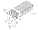
図10は実施の形態1に係る固定子1001と組み合わせて用いる可動子1002の一例を示す斜視図である。可動子1002は3つの電機子ヨーク5a、5a、5b、2つの永久磁石6a、6b、2つの補助板7a、7b、コイル8を含む。電機子ヨーク5a、5a、5bはそれぞれ直方体状をなしている。電機子ヨーク5a、5a、5bは表面に絶縁処理を施した軟磁性の珪素鋼板を積層したものである。永久磁石6a、6bは直方体状をなしている。永久磁石6a、6bの長さは電機子ヨーク5a、5a、5bと略同一となっている。永久磁石6a、6bはネオジム(Nd)、鉄(Fe)、ボロン(B)を主成分とするネオジム磁石である。ネオジム磁石に限らず、アルニコ磁石、フェライト磁石、サマリウムコバルト磁石などを用いても良い。補助板7a、7bは矩形板状をなしている。補助板7a、7bは例えばエンジニアリングプラスチック(ポリアミド、ポリカーボネイト)あるいは非磁性のセラミックなど非磁性かつ非導電体で構成する。
なお本発明において電機子ヨーク5a、5bを構成する珪素鋼板の表面の絶縁処理は必ずしも必須ではない。積層することで軟磁性体のブロックで構成する場合に比べて渦電流を低減できる。
FIG. 10 is a perspective view showing an example of the
In the present invention, the insulation treatment of the surfaces of the silicon steel plates constituting the armature yokes 5a and 5b is not always essential. The eddy current can be reduced by stacking as compared with the case of the soft magnetic block.
図10に示すように、可動子1002は電機子ヨーク5a、永久磁石6a、電機子ヨーク5b、永久磁石6b、電機子ヨーク5aを順に並べ、これらの長手方向の両端に補助板を配し、これらをコイル8が囲繞した構成としてある。図10に示す白抜き矢印は永久磁石6a、6bを構成する各磁石の磁化方向を示している。白抜矢印の終点はN極、始点はS極を示す。永久磁石6a、6bは可動子1の短手方向に沿って磁化してあり、磁化方向が互いに対向している。
As shown in FIG. 10, the
図11は実施の形態1に係る固定子1001に可動子1002を配したリニアモータの斜視図である。図11では説明の都合上、外殻部4の記載を省略している。可動子1002は第1板状部1と第2板状部2との間に配される。電機子ヨーク5bが固定子歯11と対向している場合、電機子ヨーク5a、5aは固定子歯21と対向している。
固定子歯11及び固定子歯21は、1磁気周期毎に1つずつ設けてある。固定子歯11及び固定子歯21は電気角で180度の異なる位置(1/2磁気周期ずれた位置)に設けられている。
図10及び図11に示すように、永久磁石6a、6b及び電機子ヨーク5bは、第1積層板12と第2積層板22との対向する面の法線方向の長さを略同一としてある。永久磁石6a、6b及び電機子ヨーク5bは、固定子歯11又は固定子歯21と対向する面が略面一となっている。
FIG. 11 is a perspective view of a linear motor in which a
One
As shown in FIGS. 10 and 11, the
図12はリニアモータ動作時の磁束の流れを示す説明図である。図12では、可動子1002の移動方向(紙面左右方向)に沿う部分は説明の都合上省略し、移動方向と直交する部分の断面のみ表示してある。また、外殻部4も記載を省略してある。可動子1002のコイル8に交流電流を流す。図12のコイル8に示す黒丸印は紙面の裏から表への通電、バツ印は紙面の表から裏への通電を表している(交流電流を流した際のある時点の電流の向きを示した)。コイル8の通電により、図12に点線で示したような磁束の流れが発生する。すなわち、図12に示すように固定子歯21から流れる磁束が両端の電機子ヨーク5aに流れ込み、永久磁石6a、6b内を通ってから中央部の電機子ヨーク5bに集まり、固定子歯11に抜けていく。さらに、固定子歯11から第1積層板12の櫛歯部12bに流れ込み、側板部3、第2積層板22の櫛歯部22bを抜け、固定子歯21に戻るというループとなる。電機子ヨーク5bの幅は他の2つの電機子ヨーク5a、5aの幅の2倍となっている。これは図12に示すように、電機子ヨーク5a、5aは1つの永久磁石6a又は6bと接しており、永久磁石1つ分の磁束が流れる。それに対して、電機子ヨーク5bは2つの永久磁石6a、6bと接しており、永久磁石2つ分の磁束が流れるためである。そのため、電機子ヨーク5bの幅は他の2つの電機子ヨーク5a、5aの幅の2倍とすることで、電機子ヨーク5bが磁気飽和を起こしにくくしている。
1つの固定子歯11、2つの固定子歯21は、図12に示すような磁束の流れにより、磁化される。そして、磁化された固定歯11及び固定歯21と、可動子1002の永久磁石6a及び6bとの間で吸引力及び反発力が発生する。発生した吸引力及び反発力が、可動子1002の推進力となる。可動子1002は、図12の紙面左右方向に移動する。
FIG. 12 is an explanatory diagram showing the flow of magnetic flux when the linear motor operates. In FIG. 12, portions along the moving direction (left and right direction of the paper) of the
One
図11を用いて、固定子歯12及び第2積層板22における渦電流の遮断について説明する。図11において、磁束の流れを点線矢印で、渦電流の流れる方向を実線矢印で示している。図11に示すように固定子歯11において磁束は、固定子歯11を構成する歯板片111の板面に平行な方向に流れる。渦電流は磁束の流れる方向と垂直な平面上で、磁束の変化を妨げる方向に流れようとする。第1積層板12を外側から見た場合、磁束の流れる方向を軸として時計回りに流れようとする。この渦電流の方向は固定子歯11を構成する歯板片111の板面を貫こうとする方向である。ところが、歯板片111を積層し固定子歯11が構成されているため渦電流を低減することができる。さらに板面に絶縁処理を施した場合にはさらに、歯板片111間で渦電流を低減することが可能になる。
With reference to FIG. 11, the interruption of eddy current in the
一方、第1積層板12において磁束は、図11に示すように固定子歯11から櫛歯部12bに流れ込み、櫛歯部12bの先端から根本方向に流れる。渦電流は磁束の流れる方向と垂直な平面上で、磁束の変化を妨げようとする方向に流れようとする。第1積層板12を先端から見た場合、磁束の流れる方向を軸として時計回りに流れようとする。この渦電流の方向は、第1積層板12を構成する第1板片121及び第2板片122の板面を貫こうとする方向である。ところが、第1板片121及び第2板片122を積層し第1積層板12が構成しているため渦電流を低減することができる。さらに板面に絶縁処理を施した場合には、さらに第1板片121及び第2板片122間で渦電流を低減することが可能になる。
On the other hand, in the first
図13はリニアモータ動作時の磁束の流れを示す説明図である。図11と同様、外殻部4の記載を省略している。図13に示すように、第2積層板22においても、第1積層板12と同様に渦電流が低減されることとなる。固定子歯21及び第2積層板22における渦電流の低減の原理は上述の固定子歯11及び第1積層板12と同様であるので、説明を省略する。
FIG. 13 is an explanatory diagram showing the flow of magnetic flux when the linear motor operates. As in FIG. 11, the
図14は結合部3における渦電流の低減についての説明図である。図14では図12及び図13と同様に、説明の都合上、外殻部4の記載を省略している。図14において、磁束の流れを点線矢印で、渦電流の流れる方向を実線矢印で示している。図12に示したように、固定子歯11から流れ込んだ磁束は第1積層板12の櫛歯部12bを通り、結合部3に流れこむ。結合部3に流れた磁束は第2積層板22方向に流れ、第2積層板22の櫛歯部22bに流れ込む。結合部3における磁束の流れは、図14に示すように紙面の上から下の方向である。渦電流は磁束の流れる方向と垂直な平面上で、磁束の変化を妨げようとする方向に流れようとする。結合部3を第1積層板12から第2積層板22に向かう方向(紙面の上から下方向)に眺めた場合、磁束が流れる方向を軸として時計回りに、渦電流は流れようとする。この渦電流の方向は、第3積層板31の板面を貫こうとする方向である。ところが、珪素鋼板を積層し第3積層板31を構成しているため渦電流を低減することができる。さらに板面に絶縁処理を施した場合にはさらに、各珪素鋼板間で渦電流を低減することが可能になる。なお、結合部3を流れる磁束は第3積層板31だけでなく、本体部32を流れる場合もある。しかし、磁束は最短経路を流れようとするので、第3積層板31が飽和しない限り、本体部32を流れる磁束は僅かである。
また、可動子1002が備える補助板7a、7bを非磁性かつ非導電体にて形成すると、上述した原理と同様に、電機子ヨーク5a、5bに流れる渦電流の流路を部分的に遮断することができる。
FIG. 14 is an explanatory diagram for reducing the eddy current in the
Further, when the
上述したように、実施の形態1に係るリニアモータ用固定子は、次のような効果を奏する。固定子歯11、21、第1積層板12、第2積層板22は板面を絶縁処理した珪素鋼板を積層して構成してある。各板の板面に平行な方向に磁束が流れように珪素鋼板を積層しているため、磁束の流れにより発生する渦電流の方向は板面を貫こうとする方向となる。しかしながら、珪素鋼板を積層しているため、渦電流を低減することができる。さらに板面に絶縁処理を施した場合には、さらに各珪素鋼板間で渦電流を低減することが可能になる。また、結合部3を構成する第3積層板31も同様に珪素鋼板間で渦電流を低減することができる。それにより、リニアモータ動作時に流れる渦電流を低減することができ、渦電流損を減少させることが可能となる。
なお、ここで珪素鋼板の絶縁処理は必ずしも必須ではなく、鋼板を積層することで渦電流を低減することは可能である。
ここで固定子歯11、21、第1積層板12、第2積層板22、第3積層板31をブロックではなく積層鋼板で構成した場合に渦電流を低減できる理由は、以下の様に考えられる。
珪素鋼板等の板を積層すると板面同士で接触抵抗のような電気抵抗を有する。これは板面の凹凸や軽微な酸化あるいは防錆のための油分又はカシメやリベット固定の際のわずかな歪みを起因としている。
よってブロックで形成する場合に比べて鋼板を積層する場合には、渦電流は鋼板間を貫通して流れることが少なくなり、渦電流を低減することが可能となる。
さらに積極的に板面を絶縁処理することで渦電流低減効果は高まるが、これはリニアモータに要求される仕様やコストを考慮して設定すればよい。
絶縁処理は珪素鋼板の積層面の一部のみに施しても良い。また、すべての珪素鋼板に絶縁処理を施すのではなく、絶縁処理を施した珪素鋼板と絶縁処理を施していない珪素鋼板とを積層しても良い。
As described above, the linear motor stator according to the first embodiment has the following effects. The
In addition, the insulation process of a silicon steel plate is not necessarily essential here, and it is possible to reduce an eddy current by laminating | stacking a steel plate.
The reason why the eddy current can be reduced when the
When plates such as silicon steel plates are laminated, the plate surfaces have electrical resistance such as contact resistance. This is caused by unevenness of the plate surface, slight oxidation or oil for rust prevention, or slight distortion during caulking or rivet fixing.
Therefore, in the case where the steel plates are laminated as compared with the case where the blocks are formed, the eddy current is less likely to flow through between the steel plates, and the eddy current can be reduced.
Furthermore, the eddy current reduction effect is enhanced by positively insulating the plate surface, but this may be set in consideration of specifications and costs required for the linear motor.
The insulation treatment may be performed only on a part of the laminated surface of the silicon steel plates. Moreover, not all the silicon steel plates may be subjected to insulation treatment, but a silicon steel plate subjected to insulation treatment and a silicon steel plate not subjected to insulation treatment may be laminated.
固定子歯11には耳部11aを設け、第1積層板12への固定強度を確保しているので、リニアモータ動作時に発生する磁力により、固定子歯11は第2積層板22の方向に引っ張られても、第1積層板12から固定子歯11が脱落することを防ぐことが可能となる。固定子歯21についても、固定子歯11と同様である。
Since the
第1積層板12及び第2積層板22は外殻部4で覆うので、第1積層板12及び第2積層板22の強度を確保することが可能となる。それにより、第1積層板12及び第2積層板22が変形することにより、第1積層板12より固定子歯11が脱落すること、及び第2積層板22から固定子歯22が脱落することを防ぐことが可能となる。
Since the 1st
外殻部4には爪部42aが設けられ、第1積層板12及び第2積層板22を、外殻部4の広板部41と爪部42aで挟みこむので、第1積層板12及び第2積層板22を構成する第1板片121、第2板片122剥離するのを防ぐことが可能となる。
The
また、爪部42aを設けたことにより、積層する第1板片121、第2板片122をカシメにより固定する場合でも、カシメによる固定強度を小さくすることができる。カシメの爪(舌片122d)を小さくすれば、板片間の接触面積は小さくなり、板片間の電気抵抗を大きくすることができる。それより、板片間に流れる渦電流を低減することが可能となる。
Further, by providing the
固定子歯11には貫通孔(空洞部)が設けてある。固定子歯11の製造時に積層する歯板片111の貫通孔111b(空洞部)に治具を通すことにより、歯板片111を正確に位置決めして積層することが可能となる。また、貫通孔を設けたことにより、固定子歯11の軽量化を図ることが可能となる。固定子歯21についても、固定子歯11と同様である。固定子歯11及び固定子歯21が軽量化することにより、さらに、固定子1001全体の軽量化を図ることが可能となる。なお、貫通孔111bの位置や大きさは、磁束の流れを妨げないようシミュレーションにより決定すれば良い。
The
固定子歯11、固定子歯21は所謂、スキュー配置としてあるので、ディテント力の12次以上の高調波成分を低減することが可能となる。
なお、固定子歯11、固定子歯21は、それぞれ第1積層板12、第2積層板22とは別体にて形成することとしている。それにより、固定子歯11、固定子歯21が直方体状であっても、固定子歯11、固定子歯21が取り付けられる櫛歯部12b、櫛歯部22bを傾斜させることにより、固定子歯11、固定子歯21をスキュー配置することが可能である。図15は固定子歯11、12のスキュー方向を示すための説明図である。図15は固定子歯11、21の傾きについて、模式的に示した。断面短辺E1とE2は可動子の移動方向に対して傾斜している。
Since the
The
なお、固定子歯11、固定子歯21をスキューさせるのではなく、可動子1002の電機子ヨーク5a、5b、永久磁石6a、6bをスキューさせることとしても良い。また、固定子1001は、図11に示す向きで設置されることが必須の要件ではない。設置可能な如何なる向きで使用することも可能である。第1板状部1が下側や左右側となるように設置しても良い。
Instead of skewing the
第1積層板12、第2積層板22、第3積層板31を構成する各珪素鋼板の板厚は、均一でなくても良い。固定子1001の内側の方は渦電流を効果的に防止可能な0.2〜0.5mm程度とし、外側の方は剛性向上を目的として板厚1mm程度しても良い。
The thicknesses of the silicon steel plates constituting the first
実施の形態2
実施の形態1では固定子歯11及び固定子歯21の固定子1001の延在方向に対する傾き方向は同じであったが、実施の形態2では逆方向とする。図16は実施の形態2に係る固定子歯11、12のスキュー方向を示すための説明図である。図16は固定子歯11、12の傾きについて模式的に示している。
リニアモータの固定子1001を移動方向に沿って切断した横断面図である。第1板状部1が有する固定子歯11及び第2板状部2の有する固定子歯21をスキュー配置している。すなわち、固定子1001の固定子歯11及び固定子歯21は、可動子1002の移動方向(固定子1001の延在方向)に対して傾斜するように配置してある。可動子1002については、上述の実施の形態1と同様であるので、説明を省略する。
In the first embodiment, the inclination directions of the
It is the cross-sectional view which cut | disconnected the
実施の形態2において、第1板状部1が備える固定子歯11と第2板状部2が備える固定子歯21とでは、断面短辺の傾斜の方向を逆にしてある。図16に示すように、固定子歯11の断面短辺E1、E2と固定子歯21の端面短辺E3、E4とは可動子1002の移動方向に対して傾斜している。その点は上述の実施の形態1と同様である。実施の形態2では、固定子歯部11と固定子歯21とで傾斜する方向を逆にしている。すなわち、固定子歯11の断面短辺E1、E2の傾斜方向と固定子歯21の端面短辺E3、E4とは傾斜方向が互いに逆にしてある。これは、スキュー配置したことによるこじりを抑えることを目的としている。固定子歯11、固定子歯21をスキュー配置することにより、リニアモータに発生する推力は、移動方向からスキュー角度分傾く方向に生じるので、可動子1002全体が傾きこじりを発生する場合がある。固定子歯11と固定子歯22の傾斜方向を逆にすることにより、固定子歯部11と固定子歯21により発生する移動方向に垂直な方向(横方向)の推力成分が逆向きとなる。そのため、横方向の推力成分は、互いに打ち消しあい、こじりを防止することが可能となる。
In the second embodiment, the direction of the inclination of the short side of the cross section is reversed between the
以上のように、実施の形態2においては、実施の形態1に係るリニアモータにおける効果に加え、次の効果を奏する。固定子1001の固定子歯11及び固定子歯21をスキュー配置することにより、可動子1002の電機子ヨーク5a、5b、永久磁石6a、6bをスキューさせなくても、ディテント力の12次以上の高調波成分を低減することが可能となる。また、固定子歯11と固定子歯22の傾ける向きを逆方向にすることにより、こじりを防止するという効果を奏する。
As described above, the second embodiment has the following effects in addition to the effects of the linear motor according to the first embodiment. By arranging the
実施の形態3
実施の形態1及び実施の形態2においては、単相のリニアモータ(単相分のユニット)について説明した。しかしこれに限られるものではない。
例えば単相分のユニットを可動子の進行方向に並べ3相のリニアモータを構成することも可能である。
In the first embodiment and the second embodiment, the single-phase linear motor (unit for single phase) has been described. However, it is not limited to this.
For example, a single-phase unit can be arranged in the moving direction of the mover to constitute a three-phase linear motor.
本実施の形態においては、実施の形態1又は実施の形態2に係るリニアモータにおける効果に加え、次の効果を奏する。固定子1001を複数連結することにより、リニアモータのストロークを長くすることが可能となる。また、単相ユニットを3つ連結したものを可動子とするので、単相ユニット1つの場合に比べて大きな推力を得ることが可能となる。
In the present embodiment, in addition to the effects of the linear motor according to the first or second embodiment, the following effects are achieved. By connecting a plurality of
各実施例で記載されている技術的特徴(構成要件)はお互いに組合せ可能であり、組み合わせすることにより、新しい技術的特徴を形成することができる。
今回開示された実施の形態はすべての点で例示であって、制限的なものでは無いと考えられるべきである。本発明の範囲は、上記した意味では無く、特許請求の範囲によって示され、特許請求の範囲と均等の意味及び範囲内でのすべての変更が含まれることが意図される。
The technical features (components) described in each embodiment can be combined with each other, and new technical features can be formed by combining them.
The embodiments disclosed herein are illustrative in all respects and should not be considered as restrictive. The scope of the present invention is defined not by the above-mentioned meaning but by the scope of the claims, and is intended to include all modifications within the meaning and scope equivalent to the scope of the claims.
1001 固定子
1 第1板状部(基部)
11 固定子歯(磁極歯)
11a 耳部(鍔部)
111 歯板片(金属板)
111a 耳部(鍔部)
111b 貫通孔(空洞部)
12 第1積層板
12a 長板部(連結部)
12b 櫛歯部(接続部)
12c ボルト挿通孔
12d 段差部
121 第1板片(金属板)
121a 長板部
121b 櫛歯部
121c ボルト挿通孔
122 第2板片(金属板)
122a 長板部
122b 櫛歯部
122c ボルト挿通孔
2 第2板状部(基部)
21 固定子歯(磁極歯)
211 歯板片(金属板)
211a 耳部(鍔部)
211b 貫通孔(空洞部)
22 第2積層板
22b 櫛歯部(接続部)
22c ボルト挿通孔
22d 段差部(受止部)
3 結合部
31 第3積層板
32 本体部
4 外殻部(補強部)
41 広板部
41c ボルト挿通孔
42 長板部
42a 爪部(押圧爪)
1002 可動子
5a、5b 電機子ヨーク
6a、6b 永久磁石
7a、7b 補助板
8 コイル
1001
11 Stator teeth (magnetic pole teeth)
11a Ear (buttock)
111 tooth plate (metal plate)
111a Ear (buttock)
111b Through hole (cavity)
12 1st laminated board 12a Long plate part (connection part)
12b Comb tooth part (connection part)
12c
121a
122a
21 Stator teeth (magnetic pole teeth)
211 Tooth plate pieces (metal plate)
211a Ear (buttock)
211b Through hole (cavity)
22 2nd
22c Bolt insertion hole 22d Step part (receiving part)
3
41
1002
8 coils
Claims (15)
2つの前記磁石は前記移動方向に沿って磁化してあり、磁化方向は互いに対向している可動子と、
複数の磁極歯、及び
該複数の磁極歯が並設してあり、並設方向に長い対向する一対の長尺部材を含む基部を有する固定子と
を備えるリニアモータにおいて、
各前記磁極歯は並設方向に交差し、かつ基部の対向方向に直交する方向に積層した複数の金属板を含み、
前記磁石及びヨークは、前記磁極歯と対向する面が略面一となっている
ことを特徴とするリニアモータ。 Inside the coil, two magnets each having a plate shape and three yokes are alternately arranged along the moving direction,
The two magnets are magnetized along the moving direction, and the movers are opposed to each other in the magnetization direction;
A linear motor comprising: a plurality of magnetic pole teeth; and a stator having a base including a pair of long members facing each other long in the parallel arrangement direction.
Each of the magnetic pole teeth includes a plurality of metal plates that are stacked in a direction that intersects the juxtaposed direction and is orthogonal to the opposing direction of the base,
The linear motor according to claim 1, wherein the magnet and the yoke are substantially flush with a surface facing the magnetic pole teeth.
を特徴とする請求項1に記載のリニアモータ。 Linear motors according to claim 1, wherein the metal plate, characterized in that at least a portion of the laminate surface are subjected to insulation treatment.
を特徴とする請求項1に記載のリニアモータ。 Linear motors according to claim 1 wherein each base portion, characterized in that it comprises a plurality of metal plates laminated in the opposing direction.
を特徴とする請求項3に記載のリニアモータ。 Linear motors according to claim 3 metal plates included in the respective base, characterized in that at least a portion of the laminate surface are subjected to insulation treatment.
該接続部同士を結ぶ連結部とを有すること
を特徴とする請求項1から請求項4のいずれか一項に記載のリニアモータ。 Each of the base portions is a connection portion that connects between two adjacent magnetic pole teeth;
Linear motors as claimed in any one of claims 1 to 4, characterized in that it comprises a connecting portion for connecting the connecting portions.
前記接続部は前記鍔部を受け止める受止部を有すること
を特徴とする請求項5に記載のリニアモータ。 Each of the magnetic pole teeth has a flange that protrudes in the substantially extending direction of the base,
Linear motor according to 請 Motomeko 5 you, characterized in that said connection portion having a receiving portion for receiving the flange portion.
該結合部は前記磁極歯の並設方向に直交し、かつ前記対向方向に直交する方向に積層した複数の金属板を含むこと
を特徴とする請求項1から請求項6のいずれか一項に記載のリニアモータ。 A coupling portion for coupling the base portions;
The coupling portion includes a plurality of metal plates stacked in a direction perpendicular to the parallel arrangement direction of the magnetic pole teeth and perpendicular to the facing direction. linear motors described.
を特徴とする請求項7に記載のリニアモータ。 Linear motors according to claim 7 wherein the metal plate included in the coupling portion, characterized in that at least a portion of the laminate surface are subjected to insulation treatment.
を特徴とする請求項7又は請求項8に記載のリニアモータ。 Linear motors according to claim 7 or claim 8 wherein the coupling unit is characterized by having a main body portion further overlaps the plurality of metal plates.
を特徴とする請求項1から請求項9のいずれか一項に記載のリニアモータ。 Linear motors as claimed in any one of claims 1 to claim 9 wherein the base, characterized in that it comprises a reinforcing section which covers the opposite surface of the opposing surfaces.
を特徴とする請求項10に記載のリニアモータ。 Linear motors according to claim 10 wherein the reinforcing portion is characterized in that it comprises a pressing pawl that presses the base in the stacking direction continuous to opposing surfaces from a side of the base.
を特徴とする請求項1から請求項11のいずれか一項に記載のリニアモータ。 The linear motors as claimed in any one of claims 1 to 11 each magnetic pole tooth, characterized in that it comprises a cavity extending through in the stacking direction.
を特徴とする請求項1から請求項12のいずれか一項に記載のリニアモータ。 Linear motors as claimed in any one of claims 1 to 12 other magnetic pole teeth of one of the magnetic pole teeth and the base of said base, characterized in that a staggered arrangement direction.
前記磁極歯の前記基部に平行な面の向かい合う2つの短辺は前記基部の延在方向に対し傾斜していること
を特徴とする請求項1から請求項13のいずれか一項に記載のリニアモータ。 The magnetic pole teeth have a rectangular parallelepiped shape,
14. The linear motor according to claim 1, wherein two short sides facing each other in a plane parallel to the base portion of the magnetic pole tooth are inclined with respect to an extending direction of the base portion. Ta.
を特徴とする請求項14に記載のリニアモータ。 Inclination direction of the two short sides of the magnetic pole teeth inclination direction of the two short sides of the magnetic pole teeth, and the other of said base portion having the one having the base, characterized in that opposite to each other linear motors according to claim 14.
Priority Applications (1)
| Application Number | Priority Date | Filing Date | Title |
|---|---|---|---|
| JP2013089727A JP6303284B2 (en) | 2013-04-22 | 2013-04-22 | Linear motor |
Applications Claiming Priority (1)
| Application Number | Priority Date | Filing Date | Title |
|---|---|---|---|
| JP2013089727A JP6303284B2 (en) | 2013-04-22 | 2013-04-22 | Linear motor |
Publications (3)
| Publication Number | Publication Date |
|---|---|
| JP2014217089A JP2014217089A (en) | 2014-11-17 |
| JP2014217089A5 JP2014217089A5 (en) | 2016-06-02 |
| JP6303284B2 true JP6303284B2 (en) | 2018-04-04 |
Family
ID=51942341
Family Applications (1)
| Application Number | Title | Priority Date | Filing Date |
|---|---|---|---|
| JP2013089727A Active JP6303284B2 (en) | 2013-04-22 | 2013-04-22 | Linear motor |
Country Status (1)
| Country | Link |
|---|---|
| JP (1) | JP6303284B2 (en) |
Cited By (1)
| Publication number | Priority date | Publication date | Assignee | Title |
|---|---|---|---|---|
| EP4125183A1 (en) * | 2021-07-29 | 2023-02-01 | Abb Schweiz Ag | Consolidated stator laminations |
Families Citing this family (1)
| Publication number | Priority date | Publication date | Assignee | Title |
|---|---|---|---|---|
| CN111406361B (en) * | 2017-09-26 | 2023-01-03 | 三菱电机株式会社 | Motor and method for manufacturing the same |
Family Cites Families (9)
| Publication number | Priority date | Publication date | Assignee | Title |
|---|---|---|---|---|
| JPS5980149A (en) * | 1982-10-27 | 1984-05-09 | Amada Co Ltd | Manufacture of pole teeth in linear pulse motor |
| JPH0697831B2 (en) * | 1985-11-27 | 1994-11-30 | 神鋼電機株式会社 | Skew structure linear pulse motor |
| FR2697695B1 (en) * | 1992-11-04 | 1995-01-13 | Cachan Ecole Normale Superieur | Electromechanical conversion device producing a particularly linear movement. |
| JPH10164779A (en) * | 1996-11-26 | 1998-06-19 | Fuji Electric Co Ltd | Axial gap synchronizer |
| JP3215655B2 (en) * | 1997-08-07 | 2001-10-09 | 松下冷機株式会社 | Linear motor |
| JP4352679B2 (en) * | 2002-10-03 | 2009-10-28 | ダイキン工業株式会社 | Revolving motor and compressor |
| JP4382437B2 (en) * | 2003-10-30 | 2009-12-16 | オークマ株式会社 | Linear motor |
| JP2010017072A (en) * | 2008-06-06 | 2010-01-21 | Daikin Ind Ltd | Armature core, armature, method of manufacturing armature core and method for manufacturing armature |
| JP5515689B2 (en) * | 2009-11-30 | 2014-06-11 | ダイキン工業株式会社 | Armature core |
-
2013
- 2013-04-22 JP JP2013089727A patent/JP6303284B2/en active Active
Cited By (2)
| Publication number | Priority date | Publication date | Assignee | Title |
|---|---|---|---|---|
| EP4125183A1 (en) * | 2021-07-29 | 2023-02-01 | Abb Schweiz Ag | Consolidated stator laminations |
| US11949287B2 (en) | 2021-07-29 | 2024-04-02 | Abb Schweiz Ag | Consolidated stator laminations |
Also Published As
| Publication number | Publication date |
|---|---|
| JP2014217089A (en) | 2014-11-17 |
Similar Documents
| Publication | Publication Date | Title |
|---|---|---|
| JP5991326B2 (en) | Linear motor | |
| JP5518258B2 (en) | Laminated iron core of linear motor and method of manufacturing the same | |
| KR102141793B1 (en) | Method of manufacturing a stator of a permanent magnet synchronous machine and a permanent magnet synchronous machine | |
| JP4756916B2 (en) | Vibration wave motor | |
| JP5655071B2 (en) | Linear motor | |
| AU2009255008B2 (en) | Armature core | |
| JP5418558B2 (en) | Linear motor stator and linear motor | |
| JP2007037273A (en) | Vibratory linear actuator | |
| TWI513150B (en) | Linear motor | |
| JP2013106458A (en) | Linear motor | |
| JP5224050B2 (en) | Linear motor armature, linear motor, and table feed device using the same. | |
| JP5638475B2 (en) | Laminated iron core of linear motor and method of manufacturing the same | |
| JP6303284B2 (en) | Linear motor | |
| JP6379930B2 (en) | Linear motor stator | |
| JP6455061B2 (en) | Linear motor stator | |
| EP3324526A1 (en) | Magnetic field generating member and motor including same | |
| JP5261080B2 (en) | Linear motor | |
| US10811950B2 (en) | Linear motor and device provided with linear motor | |
| JP2014217089A5 (en) | ||
| WO2022208622A1 (en) | Magnetization device and magnetization method | |
| JP2014147276A (en) | Linear motor | |
| JP2005151735A (en) | Steel plate for armature core, armature core and manufacturing method for linear motor armature | |
| JP5953688B2 (en) | Linear drive | |
| JP2014132813A (en) | Linear motor | |
| JP2014143881A (en) | Linear motor |
Legal Events
| Date | Code | Title | Description |
|---|---|---|---|
| A521 | Request for written amendment filed |
Free format text: JAPANESE INTERMEDIATE CODE: A523 Effective date: 20160408 |
|
| A621 | Written request for application examination |
Free format text: JAPANESE INTERMEDIATE CODE: A621 Effective date: 20160408 |
|
| A131 | Notification of reasons for refusal |
Free format text: JAPANESE INTERMEDIATE CODE: A131 Effective date: 20170228 |
|
| A977 | Report on retrieval |
Free format text: JAPANESE INTERMEDIATE CODE: A971007 Effective date: 20170228 |
|
| A521 | Request for written amendment filed |
Free format text: JAPANESE INTERMEDIATE CODE: A523 Effective date: 20170426 |
|
| A131 | Notification of reasons for refusal |
Free format text: JAPANESE INTERMEDIATE CODE: A131 Effective date: 20170905 |
|
| A521 | Request for written amendment filed |
Free format text: JAPANESE INTERMEDIATE CODE: A523 Effective date: 20170908 |
|
| TRDD | Decision of grant or rejection written | ||
| A01 | Written decision to grant a patent or to grant a registration (utility model) |
Free format text: JAPANESE INTERMEDIATE CODE: A01 Effective date: 20180206 |
|
| A61 | First payment of annual fees (during grant procedure) |
Free format text: JAPANESE INTERMEDIATE CODE: A61 Effective date: 20180219 |
|
| R150 | Certificate of patent or registration of utility model |
Ref document number: 6303284 Country of ref document: JP Free format text: JAPANESE INTERMEDIATE CODE: R150 |
|
| S531 | Written request for registration of change of domicile |
Free format text: JAPANESE INTERMEDIATE CODE: R313531 |
|
| S533 | Written request for registration of change of name |
Free format text: JAPANESE INTERMEDIATE CODE: R313533 |
|
| R350 | Written notification of registration of transfer |
Free format text: JAPANESE INTERMEDIATE CODE: R350 |