JP6300536B2 - Mold - Google Patents
Mold Download PDFInfo
- Publication number
- JP6300536B2 JP6300536B2 JP2014010696A JP2014010696A JP6300536B2 JP 6300536 B2 JP6300536 B2 JP 6300536B2 JP 2014010696 A JP2014010696 A JP 2014010696A JP 2014010696 A JP2014010696 A JP 2014010696A JP 6300536 B2 JP6300536 B2 JP 6300536B2
- Authority
- JP
- Japan
- Prior art keywords
- mold
- sliding
- mating surface
- cavity
- fixed mold
- Prior art date
- Legal status (The legal status is an assumption and is not a legal conclusion. Google has not performed a legal analysis and makes no representation as to the accuracy of the status listed.)
- Active
Links
Images


Description
本発明は、鋳造用の金型に関する。 The present invention relates to a casting mold.
従来、鋳造用の金型において、鋳造前(溶湯の注入前)に、キャビティを形成する金型の内壁面に、液体状の離型剤をスプレー塗布することが行われている。離型剤は、溶質としての固体状の離型剤を、溶媒である水に溶解することで調整される。そして、離型剤が塗布されると、金型の残熱で水が蒸発し、離型剤が金型の表面に薄膜状で付着することになる。 2. Description of the Related Art Conventionally, in a casting mold, before casting (before pouring molten metal), a liquid mold release agent is sprayed onto the inner wall surface of a mold that forms a cavity. The release agent is adjusted by dissolving a solid release agent as a solute in water as a solvent. When the mold release agent is applied, water is evaporated by the residual heat of the mold, and the mold release agent adheres to the surface of the mold in a thin film shape.
ここで、水が蒸発せずキャビティに残ってしまうと、水が溶湯に混入し、鋳造品の表面品質が低下してしまう。そこで、特許文献1では、上下に摺動する摺動型が差し込まれる固定型の差し込み穴の底部に、排水孔を形成する技術が記載されている。
Here, if the water does not evaporate and remains in the cavity, the water is mixed into the molten metal and the surface quality of the cast product is deteriorated. Therefore,
ところで、鋳造品の形状等によって、固定型に対して摺動型が水平方向に摺動する金型もある。このような金型では、固定型及び摺動型の間に形成される下側の合わせ面は、キャビティから略水平方向延びる第1合わせ面と、第1合わせ面から下方側に傾斜しながら外側に延びる第2合わせ面と、を備えている。傾斜した第2合わせ面は、固定型の固定型側第2合わせ面と、摺動型の摺動型側第2合わせ面とが合わさることで構成され、固定型に対する摺動型の型締め位置を決めている。 Incidentally, there is a mold in which the sliding mold slides in the horizontal direction with respect to the fixed mold depending on the shape of the cast product. In such a mold, the lower mating surface formed between the fixed mold and the sliding mold has a first mating surface extending substantially horizontally from the cavity, and an outer side inclined downward from the first mating surface. And a second mating surface extending in the direction. The inclined second mating surface is formed by combining the fixed mold-side second mating surface and the sliding-type sliding mold-side second mating surface, and the sliding mold clamping position with respect to the fixed mold Have decided.
ところが、摺動型側第2合わせ面が固定型側第2合わせ面に当接し型締めされる際、摺動型側第2合わせ面及び固定型側第2合わせ面の間の離型剤が残留しているとき、離型剤が押し潰され、キャビティに流入する虞がある。
なお、溶湯が注入されるキャビティから遠ざかるにつれて金型温度が低くなる。よって、第2合わせ面は第1合わせ面よりも低温となり易く、固定型側第2合わせ面、摺動型側第2合わせ面では、離型剤の水が蒸発せず、離型剤が液体のまま残留する場合がある。
However, when the sliding mold side second mating surface abuts on the fixed mold side second mating surface and is clamped, the mold release agent between the sliding mold side second mating surface and the fixed mold side second mating surface is removed. When it remains, the release agent may be crushed and flow into the cavity.
Note that the mold temperature decreases as the distance from the cavity into which the molten metal is injected is increased. Therefore, the temperature of the second mating surface is likely to be lower than that of the first mating surface, and the release agent water does not evaporate on the stationary mold side second mating surface and the sliding mold side second mating surface, and the mold release agent is liquid. May remain.
そこで、本発明は、キャビティへの離型剤の流入を防止する金型を提供することを課題とする。 Then, this invention makes it a subject to provide the metal mold | die which prevents the inflow of the mold release agent to a cavity.
前記課題を解決するための手段として、本発明は、キャビティと前記キャビティから外部に向かう摺動方向に延びる摺動型用差込孔とを有する固定型と、先端側が前記摺動型用差込孔に差し込まれ前記固定型に対して摺動方向において摺動可能である摺動型と、を備え、前記固定型及び前記摺動型の間に形成される合わせ面は、前記キャビティ側において摺動方向に延びる第1合わせ面と、前記第1合わせ面から外部に向かうにつれて前記摺動型用差込孔が大きくなるように傾斜しながら延びる第2合わせ面と、を備え、前記第2合わせ面は、前記固定型の固定型側第2合わせ面と、前記摺動型の摺動型側第2合わせ面とが合わさることで構成され、前記摺動型側第2合わせ面には、前記摺動型側第2合わせ面が前記固定型側第2合わせ面に合わさる際、前記摺動型側第2合わせ面及び前記固定型側第2合わせ面の間の離型剤を捕獲する凹部が形成され、前記凹部は、前記第2合わせ面に沿って、前記摺動型の摺動方向に対して直交する方向に延びる溝状であることを特徴とする金型である。 As means for solving the above-mentioned problems, the present invention provides a fixed mold having a cavity and a sliding mold insertion hole extending in a sliding direction from the cavity to the outside, and a distal end side of the sliding mold insertion. A sliding mold that is inserted into the hole and is slidable in a sliding direction with respect to the fixed mold, and a mating surface formed between the fixed mold and the sliding mold is slid on the cavity side. A first mating surface extending in a moving direction, and a second mating surface extending while inclining so that the sliding insertion hole increases from the first mating surface toward the outside. The surface is configured by combining the fixed mold side second mating surface of the fixed mold and the sliding mold side second mating surface, and the sliding mold side second mating surface includes the The sliding mold side second mating surface is the fixed mold side second mating surface. When monkey I, said recess to capture a release agent between the sliding-type-side second mating surface and the fixed mold side second mating surface is formed, said recess along said second mating surface, wherein It is a metal mold | die characterized by the groove shape extended in the direction orthogonal to the sliding direction of a sliding type | mold.
このような構成によれば、摺動型側第2合わせ面が固定型側第2合わせ面に合わさる際において、摺動型側第2合わせ面及び固定型側第2合わせ面の間に残留している液体状の離型剤が、第2合わせ面に沿って移動しつつ、摺動型側第2合わせ面に形成された凹部に捕獲される。これにより、離型剤がキャビティに流入することは防止される。よって、鋳造品の表面品質が低下することはない。
また、このような構成によれば、凹部が第2合わせ面に沿って、摺動型の摺動方向に対して直交する方向に延びる溝状であるので、溝状の凹部によって離型剤を良好に捕獲することができる。
According to such a configuration, when the sliding mold side second mating surface is mated with the fixed mold side second mating surface, it remains between the sliding mold side second mating surface and the fixed mold side second mating surface. The liquid mold release agent is captured by the recess formed on the sliding-type second mating surface while moving along the second mating surface. This prevents the release agent from flowing into the cavity. Therefore, the surface quality of the cast product does not deteriorate.
Further, according to such a configuration, since the concave portion has a groove shape extending in the direction perpendicular to the sliding direction of the sliding type along the second mating surface, the release agent is removed by the groove-shaped concave portion. Can be captured well.
また、金型において、前記摺動方向は、略鉛直方向を含み、前記摺動型は、略鉛直方向において摺動可能である鉛直方向摺動型を含むことが好ましい。 In the mold, the sliding direction preferably includes a substantially vertical direction, and the sliding mold preferably includes a vertical sliding type that is slidable in the substantially vertical direction.
また、金型において、前記摺動型には、前記凹部と外部とを連通する連通孔が形成されていることが好ましい。 In the mold, the sliding mold is preferably formed with a communication hole that communicates the concave portion with the outside.
このような構成によれば、外部から連通孔を介して凹部を吸引することにより、凹部の圧力が低下し、離型剤が凹部に捕獲され易くなる。また、凹部に捕獲された離型剤を外部に排出することもできる。 According to such a configuration, by sucking the concave portion from the outside through the communication hole, the pressure in the concave portion is reduced, and the release agent is easily captured in the concave portion. Moreover, the mold release agent captured by the recessed part can also be discharged | emitted outside.
この場合において、水平方向摺動型と鉛直方向摺動型とを備え、そして、水平方向摺動型と鉛直方向摺動型とに連通孔がそれぞれ形成された構成である場合、水平方向摺動型の連通孔と、鉛直方向摺動型の連通孔とを介して、凹部を吸引することにより、金型内への外気の流入を防止しつつ、金型内(キャビティ)を低圧で維持できる。これにより、キャビティへの溶湯の湯周りを向上させることができる。なお、後記する実施形態のように、2つの水平方向摺動型と2つの鉛直方向摺動型とを備える場合、4方向から吸引することが好ましい。これに対して、吸引経路が少ない場合、固定型と摺動型との隙間を通って外気がキャビティに流入することにより、キャビティの圧力が下がり難くなる。 In this case, when the horizontal sliding type and the vertical sliding type are provided, and the communication holes are respectively formed in the horizontal sliding type and the vertical sliding type, the horizontal sliding type is provided. By sucking the concave portion through the mold communication hole and the vertical direction sliding mold communication hole, the inside of the mold (cavity) can be maintained at a low pressure while preventing the outside air from flowing into the mold. . Thereby, the hot water circumference of the molten metal to the cavity can be improved. In addition, like the embodiment described later, when two horizontal sliding types and two vertical sliding types are provided, it is preferable to suck from four directions. On the other hand, when the number of suction paths is small, the outside air flows into the cavity through the gap between the fixed mold and the sliding mold, so that the pressure of the cavity is difficult to decrease.
本発明によれば、キャビティへの離型剤の流入を防止する金型を提供することができる。 ADVANTAGE OF THE INVENTION According to this invention, the metal mold | die which prevents the inflow of the mold release agent to a cavity can be provided.
本発明の一実施形態について、図1〜図7を参照して説明する。 An embodiment of the present invention will be described with reference to FIGS.
≪金型の構成≫
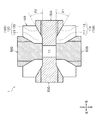
本実施形態に係る金型1は、鋳造用の金型であって、固定型10と、摺動型50A〜50Dと、を備えている。なお、ここでは説明を簡単とするために、立方体状の鋳造品を製造する場合を例示する。よって、キャビティ11も立方体状となる。ただし、鋳造品、キャビティ11の形状はこれに限定されず変更自由である。また、固定型10、摺動型50A〜50Dの形状についても変更自由である。さらに、摺動型の数についても変更自由であり、例えば、摺動型50A、50Cのみを備える構成でもよい。
≪Mold composition≫
The
<固定型>
固定型10は、原則、移動せず固定された金型であり、その外形は概ね立方体状である。固定型10は、2ピース構成であり、前側の固定型本体10Aと、後側の可動型10Bと、を備えている。なお、可動型10Bは、固定型本体10Aに対して、図示しない把持アーム、アクチュエータ等によって可動可能であり、前後方向において当接(合体)/分離するようになっている。
<Fixed type>
In principle, the
固定型10の内部には、キャビティ11と、4本の摺動型用差込孔20A〜20Dとが形成されている(図3参照)。すなわち、固定型10は、キャビティ11と、摺動型用差込孔20A〜20Dとを有している。
Inside the fixed
<固定型−キャビティ>
キャビティ11は、製造物である鋳造品に対応した形状、ここでは立方体状を呈しており、固定型10の略中心に配置されている。
<Fixed mold-cavity>
The
<固定型−摺動型用差込孔>
摺動型用差込孔20A〜20Dは、キャビティ11から外部に向かって延び外部に開口し、キャビティ11と外部とを連通させる連通孔であると共に、摺動型50A〜50Dが差し込まれる差込孔である。
<Fixed type-Sliding type insertion hole>
The sliding
摺動型用差込孔20Aは、キャビティ11の右側に連通し、この右側部分から右水平方向(摺動型50Aの摺動方向)に延び、固定型10の右側面で外部に開口する孔である。
摺動型用差込孔20Bは、キャビティ11の下側に連通し、この下側部分から鉛直下方向(摺動型50Bの摺動方向)に延び、固定型10の下面で外部に開口する孔である。
The sliding
The sliding
摺動型用差込孔20Cは、キャビティ11の左側に連通し、この左側部分から左水平方向(摺動型50Cの摺動方向)に延び、固定型10の左側面で外部に開口する孔である。
摺動型用差込孔20Dは、キャビティ11の上側に連通し、この上側部分から鉛直上方向(摺動型50Dの摺動方向)に延び、固定型10の上面で外部に開口する孔である。
The sliding mold insertion hole 20 </ b> C communicates with the left side of the
The sliding-
すなわち、摺動型用差込孔20A、20Cは、キャビティ11に連通し、略水平方向に延びている。
ここで、摺動型用差込孔20A〜20Dは、その延長方向(長手方向)が若干異なるが、その形状は略同様である。以下、摺動型用差込孔20Aについて主に説明する。
That is, the sliding-
Here, the sliding-
摺動型用差込孔20Aは、軸方向視(左右方向視)で略正四角形の孔である。摺動型用差込孔20Aは、キャビティ11側の四角孔状のストレート孔部21と、ストレート孔部21から右方に向かうにつれて徐々に拡大し外部に開口する拡大孔部22と、を備えている。
The sliding-
ストレート孔部21を囲む固定型10の内壁面のうち、下側の内壁面は固定型側下第1合わせ面21aを構成し、上側の内壁面は固定型側上第1合わせ面21bを構成している。
拡大孔部22を囲む固定型10の内壁面のうち、下側の内壁面は固定型側下第2合わせ面22aを構成し、上側の内壁面は固定型側上第2合わせ面22bを構成している。
Of the inner wall surfaces of the fixed
Of the inner wall surfaces of the fixed
<摺動型>
摺動型50A(水平方向摺動型)は、その先端側が摺動型用差込孔20Aに差し込まれ、固定型10に対して略水平方向において摺動可能である摺動型である。
摺動型50B(鉛直方向摺動型)は、その先端側が摺動型用差込孔20Bに差し込まれ、固定型10に対して略鉛直方向において摺動可能である摺動型である。
<Sliding type>
The sliding mold 50 </ b> A (horizontal sliding mold) is a sliding mold in which the tip side is inserted into the sliding mold insertion hole 20 </ b> A and can slide in the substantially horizontal direction with respect to the fixed
The sliding mold 50 </ b> B (vertical sliding mold) is a sliding mold in which the tip side is inserted into the sliding mold insertion hole 20 </ b> B and can slide in the substantially vertical direction with respect to the fixed
摺動型50C(水平方向摺動型)は、その先端側が摺動型用差込孔20Cに差し込まれ、固定型10に対して略水平方向において摺動可能である摺動型である。
摺動型50D(鉛直方向摺動型)は、その先端側が摺動型用差込孔20Dに差し込まれ、固定型10に対して略鉛直方向において摺動可能である摺動型である。
The sliding die 50 </ b> C (horizontal sliding die) is a sliding die whose front end is inserted into the sliding die insertion hole 20 </ b> C and is slidable in a substantially horizontal direction with respect to the fixed
The sliding
ここで、摺動型50A〜50Dは、差し込まれる孔が若干異なるが、その形状は略同様である。以下、摺動型50Aについて主に説明する。
Here, the sliding molds 50 </ b> A to 50 </ b> D have slightly different holes, but the shapes thereof are substantially the same. Hereinafter, the sliding
摺動型50Aは、先端側(キャビティ11側)で四角柱状を呈する先端部51と、先端部51の右端側から右方に向かうにつれて上下に拡大する拡大部52と、を備えている。
The sliding die 50 </ b> A includes a
先端部51の外壁面のうち、下側の外壁面は摺動型側下第1合わせ面51aを構成し、上側の外壁面は摺動型側上第1合わせ面51bを構成している。
拡大部52の外壁面のうち、下側の外壁面は摺動型側下第2合わせ面52aを構成し、上側の外壁面は摺動型側上第2合わせ面52bを構成している。
Of the outer wall surface of the
Of the outer wall surfaces of the
<合わせ面>
固定型10と摺動型50Aとの間に形成される合わせ面100について説明する(図2参照)。
合わせ面100は、全体として略四角筒状であり、縦断面視において、摺動型50Aの下面と固定型10との間に形成される下合わせ面110と、摺動型50Aの上面と固定型10との間に形成される上合わせ面120と、を含んでいる。なお、前後方向において固定型10と摺動型50Aとの間にも合わせ面が形成されている。
<Mating surface>
The
The
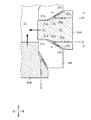
<下合わせ面>
下合わせ面110は、キャビティ11から右水平方向(摺動型50Aの摺動方向)に延びる下第1合わせ面111と、下第1合わせ面111の右端から下方に傾斜しながら右方に延びる下第2合わせ面112と、を備えている。つまり、下第2合わせ面112は、下第1合わせ面111の右端から外部に向かうにつれて摺動型用差込孔20Aが大きくなるように下方に傾斜しながら延びている。下第2合わせ面112の傾斜の程度、つまり、下第2合わせ面112と水平面との間の角度θ1は例えば1°である。なお、図2においては、理解し易くするために、角度θ1を誇張して記載している。
<Lower mating surface>
The
下第1合わせ面111は、固定型側下第1合わせ面21aと摺動型側下第1合わせ面51aとが合わさることで構成されている(図2、図3参照)。
下第2合わせ面112は、固定型側下第2合わせ面22aと摺動型側下第2合わせ面52aとが合わさることで構成されている(図2、図3参照)。
The lower
The lower
摺動型側下第2合わせ面52aには、前後方向に延びる溝53a(凹部)が形成されている。前後方向は、摺動型50Aの摺動方向(左右方向)に直交する方向である。これにより、型締めの際において、固定型側下第2合わせ面22aと摺動型側下第2合わせ面52aとの間に液体状の離型剤Pが存在していた場合、離型剤Pは溝53aで捕獲されるようになっている。なお、複数の溝53aが平行に形成された構成でもよい。
A
摺動型50Aの内部には、溝53aと外部とを連通する連通孔54aが形成されている。そして、外部から連通孔54aを介して溝53aを吸引することにより、溝53aの圧力が低下し、離型剤Pが溝53aに捕獲され易くなる。また、溝53aに捕獲された離型剤Pを外部に排出することもできる。
A
このように摺動型50Aの摺動型側下第2合わせ面52aに溝53aが形成された構成された構成であるので、他の部位によって干渉を受けずに溝加工用工具(切削工具等)で溝53aを形成でき、溝53aの設計の自由度は大きくなる。つまり、容易に加工できるので、その加工コストが下がる。これに対して、固定型側下第2合わせ面22aに溝が形成された構成である場合、溝加工用工具が固定型側上第1合わせ面21bや固定型側上第2合わせ面22bに干渉する虞があり、溝53aの設計の自由度が小さくなってしまう。
Thus, since the
<上合わせ面>
上合わせ面120は、キャビティ11から右水平方向に延びる上第1合わせ面121と、上第1合わせ面111の右端から上方に傾斜しながら右方に延びる上第2合わせ面122と、を備えている。つまり、上第2合わせ面122は、上第1合わせ面121の右端から外部に向かうにつれて摺動型用差込孔20Aが大きくなるように上方に傾斜しながら延びている。上第2合わせ面122の傾斜の程度、つまり、上第2合わせ面122と水平面との間の角度θ2は例えば1°である。
<Upper mating surface>
The
上第1合わせ面121は、固定型側上第1合わせ面21bと摺動型側上第1合わせ面51bとが合わさることで構成されている。
下第2合わせ面112は、固定型側上第2合わせ面22bと摺動型側上第2合わせ面52bとが合わさることで構成されている。
The upper
The lower
摺動型側上第2合わせ面52bには、前後方向に延びる溝53b(凹部)が形成されている。前後方向は、摺動型50Aの摺動方向(左右方向)に直交する方向である。これにより、型締めの際において、固定型側上第2合わせ面22bと摺動型側上第2合わせ面52bとの間に液体状の離型剤Pが存在していた場合、離型剤Pは溝53bで捕獲されるようになっている。なお、複数の溝53bが平行に形成された構成でもよい。
A
摺動型50Aの内部には、溝53bと外部とを連通する連通孔54bが形成されている。そして、外部から連通孔54bを介して溝53bを吸引することにより、溝53bの圧力が低下し、離型剤Pが溝53bに捕獲され易くなる。また、溝53bに捕獲された離型剤Pを外部に排出することもできる。
A
≪金型の使用方法・効果≫
金型1の使用方法及びその効果を説明する。
≪How to use and effect of molds≫
A method of using the
ここで、固定型10、摺動型50A〜50Dは、前回鋳造時における溶湯の熱により、高温となっている。固定型10、摺動型50A〜50Dの温度は、キャビティ11に近づくにつれて高く、キャビティ11から遠ざかるにつれて低くなる。
Here, the fixed
<離型剤の塗布>
図4に示すように、型開き状態において、キャビティ11、摺動型用差込孔20A〜20Dに、液体状の離型剤Pをスプレー塗布する。具体的に例えば、溶湯の注入用のゲート(図示しない)等にスプレー塗布用の極細管が挿入され、離型剤Pが噴霧される。
<Application of release agent>
As shown in FIG. 4, in a mold open state, a liquid mold release agent P is spray applied to the
そうすると、固定型10、摺動型50A〜50Dの残熱により、離型剤Pの溶媒としての水が蒸発し、キャビティ11を囲む内壁面に溶質のみから成る離型剤Pが薄膜状で塗布される。
Then, the residual heat of the fixed
ところが、キャビティ11から離れ比較的に温度が低い固定型側下第2合わせ面22a、摺動型側下第2合わせ面52a、固定型側上第2合わせ面22b、摺動型側上第2合わせ面52bに、離型剤Pが液体のまま残留する場合がある。すなわち、固定型側下第2合わせ面22a及び摺動型側下第2合わせ面52aの間、固定型側上第2合わせ面22b及び摺動型側上第2合わせ面52bの間に、離型剤Pが液体のまま残留する場合がある。
However, the fixed mold side lower
<型締め>
次いで、金型1を型締めする。
この場合において、固定型側下第2合わせ面22a及び摺動型側下第2合わせ面52aの間に離型剤Pが液体のまま残留していたとき、摺動型側下第2合わせ面52aが固定型側下第2合わせ面22aに当接すると略同時に、離型剤Pは、下第2合わせ面112に沿って移動し溝53aに捕獲される。次いで、捕獲された離型剤Pは、連通孔54aを通って、外部に排出される(図5、図6参照)。なお、吸引ポンプ等によって、摺動型50A〜50Dの連通孔54aを介して溝53aを減圧することが好ましい。すなわち、4方向からキャビティ11を吸引することが好ましい。このようにすれば、溝53a及びキャビティ11の圧力を良好に下げることができ、離型剤Pを良好に溝53aに捕獲した後、外部に排出できる。
<Clamping>
Next, the
In this case, when the release agent P remains in a liquid state between the fixed mold side lower
この場合において、例えば、固定型側上第2合わせ面22b及び摺動型側上第2合わせ面52bの間に離型剤Pが液体のまま残留していたとき、摺動型側上第2合わせ面52bが固定型側上第2合わせ面22bに当接すると略同時に、離型剤Pは、溝53bに捕獲された後、連通孔54bを通って、外部に排出される(図5、図7参照)。
In this case, for example, when the release agent P remains in the liquid state between the fixed mold side upper
このようにして、離型剤Pが溝53a等で捕獲され外部に排出されるので、離型剤Pがキャビティ11に流入することはない。したがって、この後、キャビティ11に注入される溶湯に離型剤Pが混入することはない。よって、鋳造品の表面品質が低下することはない。また、溝53a及びキャビティ11は吸引によって減圧されているので、溶湯はキャビティ11の細部にも良好に湯周りする。
In this way, the release agent P is captured by the
≪変形例≫
以上、本発明の一実施形態について説明したが、本発明はこれに限定されず、例えば、次のように変更してもよい。
≪Modification≫
As mentioned above, although one Embodiment of this invention was described, this invention is not limited to this, For example, you may change as follows.
前記した実施形態では、摺動型側下第2合わせ面に溝53aが形成された構成を例示したが、その他に例えば、図8に示すように、摺動型側下第2合わせ面に溝53aに複数の穴53c(凹部)が形成された構成でもよい。複数の穴53cは、前後方向において所定間隔をあけて配列しており、各穴53cは連通孔54aを介して外部と連通している。
In the above-described embodiment, the configuration in which the
1 金型
10 固定型
10A 固定型本体
10B 可動型
11 キャビティ
20A、20B、20C、20D 摺動型用差込孔
21 ストレート孔部
22 拡大孔部
22a 固定型側下第2合わせ面
50A、50C 摺動型(水平方向摺動型)
50B、50D 摺動型(鉛直方向摺動型)
52a 摺動型側下第2合わせ面
53a 溝(凹部)
54a 連通孔
100 合わせ面
110 下合わせ面(下側の合わせ面)
111 下第1合わせ面
112 下第2合わせ面
1
50B, 50D Sliding type (vertical sliding type)
52a Sliding mold side lower
111 Lower
Claims (3)
先端側が前記摺動型用差込孔に差し込まれ前記固定型に対して摺動方向において摺動可能である摺動型と、
を備え、
前記固定型及び前記摺動型の間に形成される合わせ面は、前記キャビティ側において摺動方向に延びる第1合わせ面と、前記第1合わせ面から外部に向かうにつれて前記摺動型用差込孔が大きくなるように傾斜しながら延びる第2合わせ面と、を備え、
前記第2合わせ面は、前記固定型の固定型側第2合わせ面と、前記摺動型の摺動型側第2合わせ面とが合わさることで構成され、
前記摺動型側第2合わせ面には、前記摺動型側第2合わせ面が前記固定型側第2合わせ面に合わさる際、前記摺動型側第2合わせ面及び前記固定型側第2合わせ面の間の離型剤を捕獲する凹部が形成され、
前記凹部は、前記第2合わせ面に沿って、前記摺動型の摺動方向に対して直交する方向に延びる溝状である
ことを特徴とする金型。 A stationary mold having a cavity and a sliding mold insertion hole extending in a sliding direction from the cavity toward the outside;
A sliding mold whose tip side is inserted into the sliding mold insertion hole and is slidable in the sliding direction with respect to the fixed mold; and
With
The mating surface formed between the fixed mold and the sliding mold has a first mating surface extending in the sliding direction on the cavity side, and the sliding mold plug as it goes from the first mating surface to the outside. A second mating surface extending while inclining so that the hole is large,
The second mating surface is configured by combining the fixed mold-side second mating surface of the fixed mold and the sliding-type sliding mold-side second mating surface,
When the sliding mold side second mating surface is aligned with the fixed mold side second mating surface, the sliding mold side second mating surface and the fixed mold side second mating surface are arranged on the sliding mold side second mating surface. A recess for capturing the release agent between the mating surfaces is formed,
The said recessed part is a groove | channel shape extended in the direction orthogonal to the sliding direction of the said sliding mold along the said 2nd mating surface .
前記摺動型は、略鉛直方向において摺動可能である鉛直方向摺動型を含む
ことを特徴とする請求項1に記載の金型。 The sliding direction includes a substantially vertical direction,
The mold according to claim 1, wherein the sliding mold includes a vertical sliding mold that is slidable in a substantially vertical direction.
ことを特徴とする請求項1または請求項2に記載の金型。 The mold according to claim 1 or 2 , wherein the sliding mold is formed with a communication hole that communicates the recess and the outside.
Priority Applications (1)
| Application Number | Priority Date | Filing Date | Title |
|---|---|---|---|
| JP2014010696A JP6300536B2 (en) | 2014-01-23 | 2014-01-23 | Mold |
Applications Claiming Priority (1)
| Application Number | Priority Date | Filing Date | Title |
|---|---|---|---|
| JP2014010696A JP6300536B2 (en) | 2014-01-23 | 2014-01-23 | Mold |
Publications (3)
| Publication Number | Publication Date |
|---|---|
| JP2015136726A JP2015136726A (en) | 2015-07-30 |
| JP2015136726A5 JP2015136726A5 (en) | 2017-01-05 |
| JP6300536B2 true JP6300536B2 (en) | 2018-03-28 |
Family
ID=53768106
Family Applications (1)
| Application Number | Title | Priority Date | Filing Date |
|---|---|---|---|
| JP2014010696A Active JP6300536B2 (en) | 2014-01-23 | 2014-01-23 | Mold |
Country Status (1)
| Country | Link |
|---|---|
| JP (1) | JP6300536B2 (en) |
Families Citing this family (2)
| Publication number | Priority date | Publication date | Assignee | Title |
|---|---|---|---|---|
| JP6320056B2 (en) * | 2014-01-28 | 2018-05-09 | 株式会社アーレスティ | Mold equipment |
| CN109571722B (en) * | 2019-01-25 | 2024-03-29 | 佛山市龙兴科技有限公司 | Mould demoulding device |
Family Cites Families (7)
| Publication number | Priority date | Publication date | Assignee | Title |
|---|---|---|---|---|
| JPH0391129U (en) * | 1989-12-29 | 1991-09-17 | ||
| JP3345842B2 (en) * | 1993-10-15 | 2002-11-18 | 株式会社アーレスティ | Die casting mold |
| JPH09122881A (en) * | 1995-11-07 | 1997-05-13 | Kiriyuu Kikai Kk | Die for vertical type pressure casting machine |
| JP2002337154A (en) * | 2001-05-21 | 2002-11-27 | Aisin Seiki Co Ltd | Mold assembly equipped with release agent discharge mechanism and release agent discharging method using the same |
| JP2011194433A (en) * | 2010-03-19 | 2011-10-06 | Honda Motor Co Ltd | Mold |
| CN102179483B (en) * | 2011-04-27 | 2013-02-20 | 广东科达机电股份有限公司 | Novel mould release agent spraying device |
| JP5733523B2 (en) * | 2011-09-29 | 2015-06-10 | トヨタ自動車株式会社 | Die casting mold |
-
2014
- 2014-01-23 JP JP2014010696A patent/JP6300536B2/en active Active
Also Published As
| Publication number | Publication date |
|---|---|
| JP2015136726A (en) | 2015-07-30 |
Similar Documents
| Publication | Publication Date | Title |
|---|---|---|
| JP6300536B2 (en) | Mold | |
| KR101810522B1 (en) | Inclined gravity casting device | |
| RU2016140864A (en) | FILLING STAND AND ASSEMBLY METHOD | |
| RU2016145919A (en) | CASTING FORM FOR MONOCRYSTAL CASTING | |
| JP2016007625A (en) | Die casting device | |
| JP4843742B1 (en) | Casting equipment | |
| US9821370B2 (en) | Mold device for forming metal in high-level vacuum environment | |
| JP2015136726A5 (en) | ||
| JP2015080801A (en) | Die device for casting | |
| JP7398313B2 (en) | casting equipment | |
| JP5706265B2 (en) | Molding equipment for casting | |
| JP6096574B2 (en) | Release agent coating apparatus and release agent coating method | |
| JP2015171718A (en) | Die for molding cast | |
| JP2012125774A (en) | Vacuum casting apparatus | |
| JP2007285192A (en) | Piston for internal combustion engine | |
| JP2007111713A (en) | Die-casting die and die-casting method | |
| CN109562445A (en) | Die casting machine | |
| JP2017506585A (en) | Creating grooves on the core surface | |
| JP2015174140A5 (en) | ||
| JP2009028758A (en) | Die and molding method | |
| CN214392237U (en) | Loader brake disc disappearance mould many ladders of case pouring system of intaking | |
| JP6767821B2 (en) | Operating device and bearing manufacturing method | |
| JP5939834B2 (en) | Chill vent and casting mold | |
| JP5881463B2 (en) | Mold for vacuum casting | |
| US20170297085A1 (en) | Die cast system for forming a component usable in a gas turbine engine |
Legal Events
| Date | Code | Title | Description |
|---|---|---|---|
| RD02 | Notification of acceptance of power of attorney |
Free format text: JAPANESE INTERMEDIATE CODE: A7422 Effective date: 20160620 |
|
| A521 | Written amendment |
Free format text: JAPANESE INTERMEDIATE CODE: A523 Effective date: 20161117 |
|
| A621 | Written request for application examination |
Free format text: JAPANESE INTERMEDIATE CODE: A621 Effective date: 20161117 |
|
| A977 | Report on retrieval |
Free format text: JAPANESE INTERMEDIATE CODE: A971007 Effective date: 20171013 |
|
| A131 | Notification of reasons for refusal |
Free format text: JAPANESE INTERMEDIATE CODE: A131 Effective date: 20171024 |
|
| A521 | Written amendment |
Free format text: JAPANESE INTERMEDIATE CODE: A523 Effective date: 20171201 |
|
| TRDD | Decision of grant or rejection written | ||
| A01 | Written decision to grant a patent or to grant a registration (utility model) |
Free format text: JAPANESE INTERMEDIATE CODE: A01 Effective date: 20180206 |
|
| A61 | First payment of annual fees (during grant procedure) |
Free format text: JAPANESE INTERMEDIATE CODE: A61 Effective date: 20180227 |
|
| R150 | Certificate of patent or registration of utility model |
Ref document number: 6300536 Country of ref document: JP Free format text: JAPANESE INTERMEDIATE CODE: R150 |