JP6299625B2 - Air conditioner for vehicles - Google Patents
Air conditioner for vehicles Download PDFInfo
- Publication number
- JP6299625B2 JP6299625B2 JP2015031333A JP2015031333A JP6299625B2 JP 6299625 B2 JP6299625 B2 JP 6299625B2 JP 2015031333 A JP2015031333 A JP 2015031333A JP 2015031333 A JP2015031333 A JP 2015031333A JP 6299625 B2 JP6299625 B2 JP 6299625B2
- Authority
- JP
- Japan
- Prior art keywords
- flow rate
- vehicle
- duct
- air
- rate adjusting
- Prior art date
- Legal status (The legal status is an assumption and is not a legal conclusion. Google has not performed a legal analysis and makes no representation as to the accuracy of the status listed.)
- Active
Links
Images


Description
本発明は、2階建て鉄道車両において、車室内に調和空気を送給ダクトで供給する車両用空調装置に関するものである。 The present invention relates to a vehicle air conditioner that supplies conditioned air to a passenger compartment through a supply duct in a two-story railway vehicle.
従来、2階建て鉄道車両における車両用空調装置では、1階部と2階部に設けられた各送給ダクトにそれぞれダンパ等の流量調整装置を設け、流量を調整することで1階部と2階部の室温を制御(循環風量制御)している。 Conventionally, in a vehicle air conditioner for a two-story railway vehicle, a flow rate adjusting device such as a damper is provided in each of the supply ducts provided on the first and second floors, and the flow rate is adjusted to adjust the first floor portion. The room temperature of the second floor is controlled (circulation air volume control).
また特許文献1の第1図に示されているように、2階建てバスの制御において、空調装置の送風口に近いダクト分岐部に流量調整用のダンパを一式設け、1階部と2階部に供給する風量を単一のダンパで調整する技術も提案されている。
In addition, as shown in FIG. 1 of
1階部と2階部の各送給ダクトにそれぞれ設けた流量調整装置で空調制御を実施する場合、一方の流量を変位すると、流量変化分が他方の送給ダクトに流入すると考えられている。このため、変位量を反映した流量を他方の流量調整装置に指示して双方の流量を協調して調整する必要があり、複雑な制御が必要とされている。 When air-conditioning control is carried out with the flow rate adjusting devices provided in the respective first and second floor feeding ducts, it is considered that when one flow rate is displaced, the flow rate change flows into the other feeding duct. . For this reason, it is necessary to instruct the flow rate reflecting the displacement amount to the other flow rate adjustment device to adjust both flow rates in a coordinated manner, and complicated control is required.
先行文献1記載の考案では2階部の快適性を優先、流量調整用のダンパを単一化することで制御の簡易化を図り、運転手による手動制御を可能にしている。ただし、空調装置の空気吐出口に近いダクト分岐部にダンパを設ける必要があるため、高い空気流速の影響を受けてダクト内に大きな圧損が発生するという課題があった。
In the device described in the
本発明は上記のような課題を解決するためになされたものであり、単一の流量調整装置で空調制御を実施するとともに、圧力損失の軽減が可能な車両用空調装置を提供するものである。 The present invention has been made to solve the above-described problems, and provides a vehicle air conditioner capable of performing air conditioning control with a single flow rate adjusting device and reducing pressure loss. .
車両用空調装置の送風口と接続されて鉄道用車体の第一の車室に調和空気を送給する第一の送給ダクトと、前記第一の送給ダクトに少なくとも1基以上設けられ、前記第一の車室に前記調和空気を送出する第一の空気吹出し口と、前記第一の送給ダクトから分岐して前記鉄道用車体の前記第一の車室の下部に隣接する第二の車室に前記調和空気を送給する第二の送給ダクトと、前記第二の送給ダクトに少なくとも1基以上設けられ、前記第二の車室に前記調和空気を送出する第二の空気吹出し口と、を備え、前記第一の送給ダクトもしくは前記第二の送給ダクトのいずれか一方の内部にのみ前記調和空気の流量を調整する流量調整装置が設置され、前記流量調整装置を前記第一の送給ダクトの内部に設置する場合には、前記第一の送給ダクトと前記第二の送給ダクトとの分岐点よりも前記第一の空気吹出し口に近い位置に設置され、かつ前記第一の空気吹出し口よりも前記車両用空調装置の送風口に近い位置に設置され、前記流量調整装置を前記第二の送給ダクトの内部に設置する場合には、前記第一の送給ダクトと前記第二の送給ダクトとの分岐点よりも前記第二の空気吹出し口に近い位置に設置され、かつ前記第二の空気吹出し口よりも前記車両用空調装置の送風口に近い位置に設置されることを特徴とする。 At least one or more of the first supply duct connected to the air outlet of the vehicle air conditioner and supplying conditioned air to the first compartment of the railway car body, and the first supply duct are provided, A first air outlet for delivering the conditioned air to the first vehicle compartment, and a second branch branched from the first supply duct and adjacent to a lower portion of the first vehicle compartment of the railway vehicle body A second supply duct for supplying the conditioned air to the vehicle compartment, and at least one or more of the second supply ducts in the second supply duct, and sending the conditioned air to the second vehicle compartment. comprising an air blow port, wherein the first flow rate adjusting device only for adjusting the flow rate of the conditioned air delivery duct or inside of one or the second feed duct noise deviation is installed, the flow rate adjustment When the device is installed inside the first feeding duct, the first feeding duct Installed at a position closer to the first air outlet than the branch point with the second supply duct, and closer to the air outlet of the vehicle air conditioner than the first air outlet In the case where the flow rate adjusting device is installed inside the second supply duct, the second air blow-off from the branch point between the first supply duct and the second supply duct. It is installed in the position near a mouth, and is installed in the position nearer the ventilation opening of the said vehicle air conditioner than said 2nd air blowing outlet.
尚、2階部の快適性を優先して制御する場合には第二の送給ダクト内部にのみ流量調整装置を設置し、1階部の快適性を優先して制御する場合には第一の送給ダクト内部にのみ流量調整装置を設置する。 When controlling the comfort of the second floor with priority, the flow rate adjusting device is installed only inside the second feeding duct, and when controlling the comfort of the first floor with priority, the first A flow control device is installed only inside the feed duct.
本発明によれば、第二の車室に調和空気を送給する第二の送給ダクト、もしくは第一の車室に調和空気を送給する第一の送給ダクトのいずれか一方の内部にのみ調和空気の流量を調整する流量調整装置を設置し、流量調整装置を制御する。簡易な制御で第一と第二の両車室の温度調整が可能であり、且つ流量調整装置の調整に伴う送給ダクト内の圧力損失を軽減する。 According to the present invention, the second the cabin feed conditioned air Kyusuru second feed duct, or conditioned air to feed Kyusuru one or the first feeding duct Neu displaced in the first cabin A flow control device that adjusts the flow rate of conditioned air only inside is installed to control the flow control device. The temperature of the first and second vehicle compartments can be adjusted with simple control, and the pressure loss in the supply duct associated with the adjustment of the flow rate adjusting device is reduced.
実施の形態1
実施の形態1では2階部の快適性を優先した例を説明する。図1は、本発明の実施の形態1に係る2階建て鉄道車両1の構造を示す側面断面図である。2階建て鉄道車両1の2階部分には調和空気を2階に送給する第一の送給ダクト2が設けられ、1階部分には調和空気を1階に送給する第二の送給ダクト3が設けられている。
In the first embodiment, an example in which priority is given to the comfort of the second floor will be described. FIG. 1 is a side sectional view showing a structure of a two-
2階建て鉄道車両1の前後何れか一方の端部に車両用空調装置4が設けられ、第一の送給ダクト2と第二の送給ダクト3とは車両用空調装置4の近くで合流して車両用空調装置4の送風口(図示せず)と接続される。車両用空調装置4は冷房、暖房の切替運転が可能であり、冷房および暖房に対応した調和空気を生成する。車両用空調装置4で生成された調和空気は、第一の送給ダクト2と第二の送給ダクト3とを通じて2階建て鉄道車両1の車内全体に送り込まれる。
A vehicle air conditioner 4 is provided at one of the front and rear ends of the two-
車両用空調装置4の内部には、車両用空調装置4で生成される調和空気の流量を制御する制御装置6が設けられており、2階建て鉄道車両1の内部に設置された図示しない1個以上の温度センサを基にして、調和空気の流量を制御する。 A control device 6 for controlling the flow rate of the conditioned air generated by the vehicle air conditioner 4 is provided inside the vehicle air conditioner 4. The flow rate of conditioned air is controlled based on at least one temperature sensor.
第二の送給ダクト3の内部には流量調整装置として、例えば流量調整用ダンパ5が設けられている。図2は実施の形態1に係る2階建て鉄道車両1の1階部の構造を示す平面図である。第一の送給ダクト2は2階建て鉄道車両1の2階部分中央に設置され、第二の送給ダクト3は2階建て鉄道車両1の1階部分中央に設置される。
For example, a flow
図3は流量調整用ダンパ5の拡大略図である。流量調整用ダンパ5の内部には羽根部7が設けられており、例えば0度(水平位置)〜90度(垂直位置)の範囲で回転可動し、任意の角度に設定、固定することが可能である。
FIG. 3 is an enlarged schematic view of the flow
図4は第一の送給ダクト2の拡大平面図であり、矢印は車両用空調装置4で生成された調和空気の流れる向きを示している。第一の送給ダクト2には、1基以上の第一の空気吹出し口8が設けられており、車両用空調装置4で生成された調和空気はそのまま第一の送給ダクト2から第一の空気吹出し口8を通じて2階建て鉄道車両1の2階車室全体に送り込まれる。
FIG. 4 is an enlarged plan view of the
図5は第二の送給ダクト3の拡大平面図であり、第二の送給ダクト3内部に設けられた流量調整用ダンパ5の設置位置を示す。矢印は車両用空調装置4で生成された調和空気の流れる向きを示している。第二の送給ダクト3には、第一の送給ダクト2と同様に1階部の車内に空気を送り込む第二の空気吹出し口9が少なくとも1基以上設けられており、調和空気は第二の空気吹出し口9を通じて2階建て鉄道車両1の1階車室全体に送り込まれる。
FIG. 5 is an enlarged plan view of the
流量調整用ダンパ5は、流速が高く圧力損失の大きな、第一の送給ダクト2と第二の送給ダクト3との分岐点からは十分に離れ、且つ車両用空調装置4から最も近い場所に設置された第二の空気吹出し口9よりも車両用空調装置4に近い場所に設けられて、2階建て鉄道車両1の1階に吹き出す第二の送給ダクト3の内部を流れる調和空気の流量を調整する。即ち、流量調整用ダンパ5は、第一の送給ダクト2と第二の送給ダクト3との分岐点よりも第二の空気吹出し口9に近い位置に設置され、かつ第二の空気吹出し口9のいずれよりも車両用空調装置4に近い位置に設置されている。
The flow
ここで、第二の送給ダクト3の内部に設けた流量調整用ダンパ5の開度調整に伴う調和空気の風量変化について説明する。図6に車両用空調装置4の風量とダクト圧損の相関図を示す。縦軸はダクト全体の静圧を示し、横軸にはダクト全体の風量を示す。
Here, the change in the air volume of the conditioned air accompanying the adjustment of the opening degree of the flow
G1は車両用空調装置4(室内送風機)の特性曲線を表しており、車両用空調装置4で生成する調和空気の総風量Qの増加に伴い静圧Pは小さくなっていく。G3は1階部の第二の送給ダクト3内部に設置した流量調整用ダンパ5の開度を最も絞った場合の圧損曲線を示しており、風量の増加に伴いダクト圧損は増加する。
G1 represents the characteristic curve of the vehicle air conditioner 4 (indoor fan), and the static pressure P decreases as the total air volume Q of the conditioned air generated by the vehicle air conditioner 4 increases. G3 shows the pressure loss curve when the opening degree of the flow
このとき、G3とG1との交差点の風量Q1が流量調整用ダンパ5の開度を最も絞った場合の第一の送給ダクト2と第二の送給ダクト3とに送給される調和空気の総風量となり、P1が第一の送給ダクト2と第二の送給ダクト3の総圧力損失となる。
At this time, the conditioned air supplied to the
G2は流量調整用ダンパ5の開度を最も拡げた時の圧損曲線を示しており、風量増加に伴いダクト圧損は増加するが、G3と比較すると緩やかな曲線になる。
G2とG1との交差点の風量Q0が流量調整用ダンパ5の開度を最も拡げた場合の第一の送給ダクト2と第二の送給ダクト3とに送給される調和空気の総風量となり、P2が第一の送給ダクト2と第二の送給ダクト3の総圧力損失となる。
G2 shows a pressure loss curve when the opening degree of the flow
Total air volume of conditioned air supplied to the
流量調整用ダンパ5の開度調整により、総圧力損失はP2とP1の範囲で変化する。このとき、車両用空調装置4の総風量もQ0とQ1の範囲で変化する。従来考えられていたように、流量調整用ダンパ5の開度調整が第一の送給ダクト2に影響を与える、つまり流量調整用ダンパ5の開度を絞った場合に第一の送給ダクト2の風量が増加するのであれば、総風量Q0とQ1で変化が発生しないか、あるいは非常に少ない変化量になると考えられるが、実際には総圧力損失の増加に伴い総風量は明らかに減少している。
The total pressure loss changes in the range of P2 and P1 by adjusting the opening of the
圧力損失は流量調整用ダンパ5を調整する第二の送給ダクト3で発生する増加量が大きく、風量の減少は主に第二の送給ダクト3で発生する。この結果、流量調整用ダンパ5で開度調整を実施した場合でも、車両用空調装置4から第一の送給ダクト2に送給する風量に大きな変化は発生せず、第一の送給ダクト2への流量調整装置の設置と風量制御は必ずしも必要ではない。
The pressure loss has a large increase amount generated in the
なお、流量調整用ダンパ5を第一の送給ダクト2の内部に設けた場合においては、圧力損失は流量調整用ダンパ5を調整する第一の送給ダクト2で発生する増加量が大きく、風量の減少は主に第一の送給ダクト2で発生し、車両用空調装置4から第二の送給ダクト3に送給する風量に大きな変化は発生せず、第二の送給ダクト3への流量調整装置の設置と風量制御は必ずしも必要ではない。
In the case where the flow
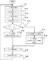
以下に、冷房運転時における流量調整用ダンパ5の開度制御について説明する。流量調整用ダンパ5の開度制御は制御装置6で実施する。図7は流量調整用ダンパ5の開度制御を示すフローチャートである。制御の基本的な考え方としては、1階部に比較して視野の広い2階部に乗客が搭乗するケースが多く見受けられることから、2階部の快適性維持を優先する。
Hereinafter, the opening degree control of the flow
2階建て鉄道車両1には1階部と2階部の車室にそれぞれ1個以上の図示しない温度センサが設けられており、常時車内の温度を検知している。まず温度センサで1階部の室温を測定し(ステップS11)、測定した室温の平均値を1階室温T_1Fとして算出する(ステップS12)。
The two-
同様に温度センサで2階部の室温を測定し(ステップS13)、測定した室温の平均値を2階室温T_2Fとして算出する(ステップS14)。次にステップS12で算出した1階室温T_1FとステップS14で算出した2階室温T_2Fとを比較、温度差を算出する(ステップS15)。 Similarly, the room temperature of the second floor is measured by the temperature sensor (step S13), and the average value of the measured room temperature is calculated as the second floor room temperature T_2F (step S14). Next, the first floor room temperature T_1F calculated in step S12 is compared with the second floor room temperature T_2F calculated in step S14, and a temperature difference is calculated (step S15).
ステップS15の結果、1階室温T_1Fと2階室温T_2Fとの温度差が1℃未満の場合には温度の再調整は不要とする。このとき、流量調整用ダンパ5は定格風量の開度を例えば30度として指示する(ステップS16)。尚、現時点で定格風量の開度に設定されている場合には、現在の開度を維持する。
As a result of step S15, when the temperature difference between the first floor room temperature T_1F and the second floor room temperature T_2F is less than 1 ° C., it is not necessary to readjust the temperature. At this time, the flow
ステップS15の結果、1階室温T_1Fと2階室温T_2Fとの温度差が1℃以上の場合には、流量調整用テーブルとして流量調整用ダンパ5の設定開度を登録したダンパ開度制御テーブルを参照する(ステップS17)。図8は冷房運転時のダンパ開度制御テーブルであり、温度差に対応したダンパ開度を登録している(ステップS18)。
As a result of step S15, when the temperature difference between the first floor room temperature T_1F and the second floor room temperature T_2F is 1 ° C. or more, the damper opening degree control table in which the set opening degree of the flow
ここで、ステップS17で参照するダンパ開度制御テーブルの考え方を示す。ダンパ開度制御テーブルには、ダンパ開度の設定値を3段階に分けて登録している。 Here, the concept of the damper opening degree control table referred to in step S17 is shown. In the damper opening degree control table, the setting values of the damper opening degree are registered in three stages.
2階部の室温が1階部の室温に比較して1℃以上高い場合には、速やかに2階部の快適性を回復する必要がある。このため、1階部に送り込む調和空気が最小限となるような開度、例えば45度に流量調整用ダンパ5の開度を指示する。結果として1階部の温度が上昇する一方で2階部の温度が下降、1階部と2階部との温度差が1℃未満になるまで同じ開度を維持する。
When the room temperature of the second floor is higher by 1 ° C. or more than the room temperature of the first floor, it is necessary to quickly restore the comfort of the second floor. For this reason, the opening degree of the flow
2階部の室温が1階部の室温に比較して低い場合には2段階の制御を行う。1階室温との温度差が2℃以上ある場合には2階部の室温が冷えすぎている可能性が高いため、2階部に送り込む調和空気が最小限となるような開度、例えば0度(水平位置)に流量調整用ダンパ5の開度を指示、1階部への送給風量を最大にする。結果として1階部の室温が下降する一方で2階部の室温は上昇、1階部と2階部との温度差が1℃未満になるまで同じ開度を維持する。
When the room temperature of the second floor is lower than the room temperature of the first floor, two-stage control is performed. When the temperature difference from the first floor room temperature is 2 ° C. or more, it is highly possible that the second floor room temperature is too cold. The degree of opening of the flow
2階部の室温と1階部の室温との温度差が1℃以上2℃未満の場合には、2階部の快適性は損なわれておらず、室温の変化量も小さいことから定格風量の開度、例えば30度に流量調整用ダンパ5の開度を指示する。
If the temperature difference between the room temperature on the second floor and the room temperature on the first floor is between 1 ° C and less than 2 ° C, the comfort of the second floor is not impaired and the change in room temperature is small, so the rated air volume The opening degree of the flow
ステップS16で定格風量の開度を指示後、あるいはステップS18で参照したダンパ開度制御テーブルの開度を指示後、流量調整用ダンパ5の開度を設定する(ステップS19)。このとき、室温に変化が現れるには一定の時間が必要となる。このため、例えば3分間、次の制御を開始するまでの処理保留時間を設定、チャタリングの発生を回避する(ステップS20)。
After instructing the opening degree of the rated air volume in step S16 or instructing the opening degree of the damper opening degree control table referred in step S18, the opening degree of the flow
この実施の形態1によれば、第二の送給ダクト3に設置した流量調整用ダンパ5のみを制御することで、2階部の快適性を維持することが可能である。また、流量調整用ダンパ5を第二の送給ダクト3の適切な位置に設置することで、第一の送給ダクト2と第二の送給ダクト3とで発生する総圧力損失を軽減することが可能である。
According to the first embodiment, it is possible to maintain the comfort of the second floor by controlling only the flow
尚、ダンパ開度制御のテーブルは最も簡易な例として3段階の開度を設定したが、3段階に限定するものではなく、温度差のレンジ幅を広げて3段階以上のテーブルを設けても構わない。また、流量調整用ダンパ5の設定開度も「45度」「30度」「0度」に限定するものではなく、車体寸法や乗客定員数等に応じた最適な開度設定により、快適性の向上が可能である。
The damper opening degree control table is set to a three-stage opening degree as the simplest example, but is not limited to the three-stage opening, and a table having three or more stages can be provided by widening the range of the temperature difference. I do not care. Also, the set opening of the flow
加えて、処理保留時間は3分に限定するものでなく、車体寸法や乗客定員数等に応じて最適な効率を期待できる時間を設定してもよい。 In addition, the processing suspension time is not limited to 3 minutes, and a time during which optimum efficiency can be expected according to the vehicle body dimensions, the passenger capacity, and the like may be set.
実施の形態1では2階部の快適性を優先するために第二の送給ダクト3にのみ流量調整用ダンパ5を設けたが、実施の形態1の変形例として、第一の送給ダクト2にのみ流量調整用ダンパ5を設けることで、1階部の快適性を優先して制御することが可能である。
In the first embodiment, the
図9は実施の形態1の変形例における第一の送給ダクト2の拡大平面図であり、第一の送給ダクト2内部に設けられた流量調整用ダンパ5の設置位置を示す。図10は実施の形態1の変形例における第二の送給ダクト3の拡大図である。尚、矢印は車両用空調装置4で生成された調和空気の流れる向きを示している。
FIG. 9 is an enlarged plan view of the
実施の形態1の他の変形例として、2階建て鉄道車両1の1階部分に設けられる第二の送給ダクト10が2階建て鉄道車両1の左右両側面に設置される場合について説明する。図11は実施の形態1の変形例に係る2階建て鉄道車両1の1階部を示す平面図である。
As another modification of the first embodiment, a case will be described in which the
第二の送給ダクト10は2階建て鉄道車両1の1階部の車室において、車両用空調装置4の送風口との接続箇所を起点として、2階建て鉄道車両1の1階部左右両側面に分かれた形状で設置される。このとき、流量調整用ダンパ11と流量調整用ダンパ12とを左右両側面に分かれた第二の送給ダクト10内の実施の形態1で示した位置と同様の場所にそれぞれ設置する。
The
流量調整用ダンパ11と流量調整用ダンパ12は実施の形態1で示したフローチャートで制御される。この結果、流量調整用ダンパ11と流量調整用ダンパ12が個々に独立した動作を行うことはなく、同一の動作を実施するため、第二の送給ダクト10の形状が異なる場合においても、実施の形態1と同様の効果を得ることが可能である。
The flow rate adjusting damper 11 and the flow
尚、2階建て鉄道車両1の2階部の車室に設けられる第一の送給ダクト2は、2階建て鉄道車両1の2階中央部、2階左右両側面のいずれに設置しても構わない。
The
実施の形態2
この発明の実施の形態2として、暖房運転時における流量調整用ダンパ5の開度制御で参照するダンパ開度制御テーブルについて説明する。図12は暖房運転時のダンパ開度制御テーブルである。構成、制御手順は実施の形態1に示した内容と同一であり、各構成品の説明は省略する。
As a second embodiment of the present invention, a damper opening degree control table referred to in opening degree control of the flow
実施の形態2に係るダンパ開度制御テーブルには、冷房運転時と同様に開度の設定値を3段階に分けて登録する。暖房時、車両用空調装置4で暖められた調和空気は冷たい車内空気よりも比重が小さいため、2階部に流れようとする特性がある。そのため、ダンパ開度制御テーブルに登録する流量調整用ダンパ5の開度は、冷房時とは異なる開度を設定する。
In the damper opening degree control table according to
2階部の室温が1階部の室温に比較して高い場合には2段階の制御を行う。1階室温との温度差が2℃以上ある場合には2階部の室温が暖まりすぎている可能性が高いため、2階部に送り込む調和空気が最小限となるような開度、例えば0度(水平位置)に流量調整用ダンパ5の開度を設定、1階部への送給風量を最大にする。結果として1階部の室温が上昇する一方で2階部の室温が下降、1階部と2階部との温度差が1℃未満になるまで同じ開度を継続する。
When the room temperature of the second floor is higher than the room temperature of the first floor, two-stage control is performed. When the temperature difference from the first floor room temperature is 2 ° C. or more, there is a high possibility that the room temperature of the second floor is too warm, so that the conditioned air sent to the second floor is minimized, for example, 0 The opening degree of the flow
1階部の室温との温度差が1℃以上2℃未満の場合には、2階部の快適性は損なわれておらず、室温の変化量も小さなことから、定格風量の開度、例えば25度で流量調整用ダンパ5の開度を設定する。
When the temperature difference between the first floor and the room temperature is 1 ° C. or more and less than 2 ° C., the comfort of the second floor is not impaired and the change in the room temperature is small. The opening degree of the flow
2階部の室温が1階部の室温に比較して1℃以上低い場合には、速やかに2階部の快適性を回復する必要がある。このため、1階部に送り込む調和空気が最小となるような開度、例えば40度に流量調整用ダンパ5の開度を設定、1階部への送給風量を最小にする。結果として1階部の温度が下降する一方で2階部の温度が上昇、1階部と2階部との温度差が1℃未満になるまで同じ開度を維持する。
When the room temperature of the second floor is lower by 1 ° C. or more than the room temperature of the first floor, it is necessary to quickly restore the comfort of the second floor. Therefore, the opening degree of the flow
この実施の形態2によれば、暖房時においても第二の送給ダクト3に設置した流量調整用ダンパ5のみを制御することで、2階部の快適性を維持することが可能である。また、流量調整用ダンパ5を第二の送給ダクト3の適切な位置に設置することで、第一の送給ダクト2と第二の送給ダクト3とで発生する総圧力損失を軽減することが可能である。
According to the second embodiment, it is possible to maintain the comfort of the second floor by controlling only the flow
暖房時においても、ダンパ開度制御のテーブルを3段階に限定するものではなく、温度差のレンジ幅を広げて3段階以上のテーブルを設けても構わない。また、流量調整用ダンパ5の設定開度も「40度」「25度」「0度」に限定するものではなく、車体寸法や乗客定員数等に応じた最適な開度設定により、快適性の向上が可能である。
Even during heating, the damper opening degree control table is not limited to three stages, and a table having three or more stages may be provided by widening the range of the temperature difference. In addition, the opening degree of the
1 2階建て鉄道車両、2 第一の送給ダクト、3 第二の送給ダクト、4 車両用空調装置、5 流量調整用ダンパ、6 制御装置、7 羽根部、8 第一の空気吹出し口、9 第二の空気吹出し口
DESCRIPTION OF
Claims (5)
前記第一の送給ダクトに少なくとも1基以上設けられ、前記第一の車室に前記調和空気を送出する第一の空気吹出し口と、
前記第一の送給ダクトから分岐して前記鉄道用車体の前記第一の車室の下部に隣接する第二の車室に前記調和空気を送給する第二の送給ダクトと、
前記第二の送給ダクトに少なくとも1基以上設けられ、前記第二の車室に前記調和空気を送出する第二の空気吹出し口と、
を備え、
前記第一の送給ダクトもしくは前記第二の送給ダクトのいずれか一方の内部にのみ前記調和空気の流量を調整する流量調整装置が設置され、
前記流量調整装置を前記第一の送給ダクトの内部に設置する場合には、前記第一の送給ダクトと前記第二の送給ダクトとの分岐点よりも前記第一の空気吹出し口に近い位置に設置され、かつ前記第一の空気吹出し口よりも前記車両用空調装置の送風口に近い位置に設置され、前記流量調整装置を前記第二の送給ダクトの内部に設置する場合には、前記第一の送給ダクトと前記第二の送給ダクトとの分岐点よりも前記第二の空気吹出し口に近い位置に設置され、かつ前記第二の空気吹出し口よりも前記車両用空調装置の送風口に近い位置に設置されることを特徴とする車両用空調装置。 A first supply duct connected to the air vent of the vehicle air conditioner and supplying conditioned air to the first compartment of the railway vehicle body;
A first air outlet provided in at least one of the first supply ducts, for sending the conditioned air to the first vehicle compartment;
A second feeding duct that branches from the first feeding duct and feeds the conditioned air to a second casing adjacent to a lower part of the first casing of the railway vehicle body;
A second air outlet provided in at least one of the second supply ducts, for sending the conditioned air to the second casing;
With
Flow control devices for regulating the flow rate of the conditioned air only to the inside of one or the first feeding duct or the second feed duct noise deviation is installed,
In the case where the flow rate adjusting device is installed inside the first supply duct, the first air outlet is located at a point more than the branch point between the first supply duct and the second supply duct. When installed in a position close to the air outlet of the vehicle air conditioner than the first air outlet, and when the flow rate adjusting device is installed inside the second supply duct Is installed at a position closer to the second air outlet than the branch point between the first feeding duct and the second feeding duct, and for the vehicle than the second air outlet. An air conditioner for a vehicle, which is installed at a position close to an air outlet of the air conditioner.
冷房運転時に、前記第一の車室の平均温度と前記第二の車室の平均温度の差が前記許容範囲内になく、前記流量調整装置が配置されていない送給ダクトに対応する車室の平均温度が前記流量調整装置の配置されている送給ダクトに対応する車室の平均温度よりも高い場合、および、暖房運転時に、前記第一の車室の平均温度と前記第二の車室の平均温度の差が前記許容範囲内になく、前記流量調整装置が配置されていない送給ダクトに対応する車室の平均温度が前記流量調整装置の配置されている送給ダクトに対応する車室の平均温度よりも低い場合は、前記流量調整装置の開度を前記定格風量の開度よりも小さくするような調整情報の設定を可能とすることを特徴とする請求項2〜4のいずれか1項に記載の車両用空調装置。During cooling operation, the difference between the average temperature of the first casing and the average temperature of the second casing is not within the allowable range, and the casing corresponds to a feeding duct in which the flow rate adjusting device is not disposed. When the average temperature of the first vehicle compartment is higher than the average temperature of the vehicle compartment corresponding to the feeding duct in which the flow rate adjusting device is disposed, and during the heating operation, the average temperature of the first vehicle compartment and the second vehicle The difference in the average temperature of the chamber is not within the allowable range, and the average temperature of the compartment corresponding to the supply duct where the flow rate adjusting device is not arranged corresponds to the supply duct where the flow rate adjusting device is arranged. The adjustment information can be set so that the opening degree of the flow rate adjusting device is smaller than the opening degree of the rated air volume when the temperature is lower than the average temperature of the passenger compartment. The vehicle air conditioner according to any one of the preceding claims.
Priority Applications (1)
| Application Number | Priority Date | Filing Date | Title |
|---|---|---|---|
| JP2015031333A JP6299625B2 (en) | 2015-02-20 | 2015-02-20 | Air conditioner for vehicles |
Applications Claiming Priority (1)
| Application Number | Priority Date | Filing Date | Title |
|---|---|---|---|
| JP2015031333A JP6299625B2 (en) | 2015-02-20 | 2015-02-20 | Air conditioner for vehicles |
Publications (3)
| Publication Number | Publication Date |
|---|---|
| JP2016153251A JP2016153251A (en) | 2016-08-25 |
| JP2016153251A5 JP2016153251A5 (en) | 2017-02-23 |
| JP6299625B2 true JP6299625B2 (en) | 2018-03-28 |
Family
ID=56760863
Family Applications (1)
| Application Number | Title | Priority Date | Filing Date |
|---|---|---|---|
| JP2015031333A Active JP6299625B2 (en) | 2015-02-20 | 2015-02-20 | Air conditioner for vehicles |
Country Status (1)
| Country | Link |
|---|---|
| JP (1) | JP6299625B2 (en) |
Families Citing this family (1)
| Publication number | Priority date | Publication date | Assignee | Title |
|---|---|---|---|---|
| FR3064237B1 (en) * | 2017-03-24 | 2019-04-26 | Alstom Transport Technologies | MONOBLOC EQUIPMENT FOR TREATING AIR OF A CAR, IN PARTICULAR A RAILWAY VEHICLE, COMPRISING AT LEAST TWO ROOMS |
Family Cites Families (3)
| Publication number | Priority date | Publication date | Assignee | Title |
|---|---|---|---|---|
| JPH01176512U (en) * | 1988-06-06 | 1989-12-15 | ||
| JPH1134633A (en) * | 1997-05-21 | 1999-02-09 | Denso Corp | Air conditioner for vehicle |
| JP3422415B2 (en) * | 1999-11-19 | 2003-06-30 | 川崎重工業株式会社 | Vehicle air conditioning and ventilation system |
-
2015
- 2015-02-20 JP JP2015031333A patent/JP6299625B2/en active Active
Also Published As
| Publication number | Publication date |
|---|---|
| JP2016153251A (en) | 2016-08-25 |
Similar Documents
| Publication | Publication Date | Title |
|---|---|---|
| CN105015301B (en) | System for improving vehicle rear passenger's climatic comfort | |
| US20170267065A1 (en) | Air conditioning system for vehicle | |
| US20180117987A1 (en) | Air conditioning unit for vehicle seat | |
| WO2020026634A1 (en) | Vehicular air conditioning device | |
| US20170087962A1 (en) | Automobile air conditioner | |
| US20100052364A1 (en) | Vehicle cowl box structure | |
| KR20160121700A (en) | Air conditioner for vehicle | |
| JP6299625B2 (en) | Air conditioner for vehicles | |
| KR20120104942A (en) | Vehicle air conditioning apparatus | |
| WO2016056186A1 (en) | Vehicle air conditioner | |
| JP6121161B2 (en) | Vehicle air conditioning system and railway vehicle equipped with the same | |
| CN111703272B (en) | Vehicle rear row air conditioner device and vehicle | |
| US20070207719A1 (en) | Heater or Air Conditioner for a Vehicle | |
| WO2019097914A1 (en) | Air conditioning system | |
| KR101767038B1 (en) | Air conditioner system for vehicle | |
| JP6958276B2 (en) | Air conditioning system | |
| WO2020012627A1 (en) | Railcar | |
| JP2712658B2 (en) | Bus air conditioner | |
| JP2005343390A (en) | Method for controlling air volume independently controllable air-conditioner unit | |
| EP3617029B1 (en) | Rail train and air conditioner duct thereof | |
| EP4183657A1 (en) | Railroad car | |
| JP2005335473A (en) | Method for controlling air-volume independently controllable air-conditioner unit | |
| JP2016153251A5 (en) | ||
| JP3597515B2 (en) | Vehicle ventilation system | |
| JPS6374710A (en) | Air-conditioner for automobile |
Legal Events
| Date | Code | Title | Description |
|---|---|---|---|
| A521 | Written amendment |
Free format text: JAPANESE INTERMEDIATE CODE: A523 Effective date: 20170116 |
|
| A621 | Written request for application examination |
Free format text: JAPANESE INTERMEDIATE CODE: A621 Effective date: 20170116 |
|
| A977 | Report on retrieval |
Free format text: JAPANESE INTERMEDIATE CODE: A971007 Effective date: 20171025 |
|
| A131 | Notification of reasons for refusal |
Free format text: JAPANESE INTERMEDIATE CODE: A131 Effective date: 20171031 |
|
| A521 | Written amendment |
Free format text: JAPANESE INTERMEDIATE CODE: A523 Effective date: 20171225 |
|
| TRDD | Decision of grant or rejection written | ||
| A01 | Written decision to grant a patent or to grant a registration (utility model) |
Free format text: JAPANESE INTERMEDIATE CODE: A01 Effective date: 20180130 |
|
| A61 | First payment of annual fees (during grant procedure) |
Free format text: JAPANESE INTERMEDIATE CODE: A61 Effective date: 20180212 |
|
| R151 | Written notification of patent or utility model registration |
Ref document number: 6299625 Country of ref document: JP Free format text: JAPANESE INTERMEDIATE CODE: R151 |
|
| R250 | Receipt of annual fees |
Free format text: JAPANESE INTERMEDIATE CODE: R250 |
|
| R250 | Receipt of annual fees |
Free format text: JAPANESE INTERMEDIATE CODE: R250 |
|
| R250 | Receipt of annual fees |
Free format text: JAPANESE INTERMEDIATE CODE: R250 |