JP6296793B2 - Epitaxial structure, method for forming the same, and device including the same - Google Patents
Epitaxial structure, method for forming the same, and device including the same Download PDFInfo
- Publication number
- JP6296793B2 JP6296793B2 JP2013503882A JP2013503882A JP6296793B2 JP 6296793 B2 JP6296793 B2 JP 6296793B2 JP 2013503882 A JP2013503882 A JP 2013503882A JP 2013503882 A JP2013503882 A JP 2013503882A JP 6296793 B2 JP6296793 B2 JP 6296793B2
- Authority
- JP
- Japan
- Prior art keywords
- poly
- film
- ink
- substrate
- silane
- Prior art date
- Legal status (The legal status is an assumption and is not a legal conclusion. Google has not performed a legal analysis and makes no representation as to the accuracy of the status listed.)
- Active
Links
- 238000000034 method Methods 0.000 title claims description 101
- 239000000758 substrate Substances 0.000 claims description 125
- BLRPTPMANUNPDV-UHFFFAOYSA-N Silane Chemical compound [SiH4] BLRPTPMANUNPDV-UHFFFAOYSA-N 0.000 claims description 112
- 229910000077 silane Inorganic materials 0.000 claims description 111
- 239000004065 semiconductor Substances 0.000 claims description 70
- 229910052751 metal Inorganic materials 0.000 claims description 68
- 239000002184 metal Substances 0.000 claims description 68
- 229910052710 silicon Inorganic materials 0.000 claims description 65
- 239000010703 silicon Substances 0.000 claims description 62
- 239000000463 material Substances 0.000 claims description 58
- 239000002019 doping agent Substances 0.000 claims description 56
- 238000007639 printing Methods 0.000 claims description 47
- 238000000576 coating method Methods 0.000 claims description 46
- 239000011248 coating agent Substances 0.000 claims description 44
- 239000007791 liquid phase Substances 0.000 claims description 41
- 229910000078 germane Inorganic materials 0.000 claims description 37
- 239000002243 precursor Substances 0.000 claims description 33
- 239000013078 crystal Substances 0.000 claims description 30
- 238000005530 etching Methods 0.000 claims description 21
- 238000000151 deposition Methods 0.000 claims description 19
- 238000004140 cleaning Methods 0.000 claims description 16
- 238000004519 manufacturing process Methods 0.000 claims description 16
- 229910052732 germanium Inorganic materials 0.000 claims description 15
- GNPVGFCGXDBREM-UHFFFAOYSA-N germanium atom Chemical compound [Ge] GNPVGFCGXDBREM-UHFFFAOYSA-N 0.000 claims description 14
- 238000010438 heat treatment Methods 0.000 claims description 14
- 239000002178 crystalline material Substances 0.000 claims description 11
- 229910021332 silicide Inorganic materials 0.000 claims description 11
- 229910052796 boron Inorganic materials 0.000 claims description 9
- 229910052759 nickel Inorganic materials 0.000 claims description 9
- 238000000059 patterning Methods 0.000 claims description 9
- 229910052698 phosphorus Inorganic materials 0.000 claims description 9
- 229910052785 arsenic Inorganic materials 0.000 claims description 8
- 239000007788 liquid Substances 0.000 claims description 8
- 229910052763 palladium Inorganic materials 0.000 claims description 8
- 238000007650 screen-printing Methods 0.000 claims description 8
- 229910052787 antimony Inorganic materials 0.000 claims description 7
- 238000004544 sputter deposition Methods 0.000 claims description 7
- 238000007607 die coating method Methods 0.000 claims description 6
- 238000007765 extrusion coating Methods 0.000 claims description 6
- 238000007646 gravure printing Methods 0.000 claims description 6
- 229910052750 molybdenum Inorganic materials 0.000 claims description 6
- 238000010248 power generation Methods 0.000 claims description 6
- 238000005507 spraying Methods 0.000 claims description 6
- 229910052721 tungsten Inorganic materials 0.000 claims description 6
- ZOXJGFHDIHLPTG-UHFFFAOYSA-N Boron Chemical compound [B] ZOXJGFHDIHLPTG-UHFFFAOYSA-N 0.000 claims description 5
- OAICVXFJPJFONN-UHFFFAOYSA-N Phosphorus Chemical compound [P] OAICVXFJPJFONN-UHFFFAOYSA-N 0.000 claims description 5
- WATWJIUSRGPENY-UHFFFAOYSA-N antimony atom Chemical compound [Sb] WATWJIUSRGPENY-UHFFFAOYSA-N 0.000 claims description 5
- RQNWIZPPADIBDY-UHFFFAOYSA-N arsenic atom Chemical compound [As] RQNWIZPPADIBDY-UHFFFAOYSA-N 0.000 claims description 5
- 229910052804 chromium Inorganic materials 0.000 claims description 5
- 229910052802 copper Inorganic materials 0.000 claims description 5
- 238000007641 inkjet printing Methods 0.000 claims description 5
- 239000011574 phosphorus Substances 0.000 claims description 5
- 238000004528 spin coating Methods 0.000 claims description 5
- 229910052715 tantalum Inorganic materials 0.000 claims description 5
- 238000001459 lithography Methods 0.000 claims description 4
- 230000003287 optical effect Effects 0.000 claims description 4
- 238000001020 plasma etching Methods 0.000 claims description 4
- 229910052697 platinum Inorganic materials 0.000 claims description 4
- 229910052793 cadmium Inorganic materials 0.000 claims description 3
- 229910052737 gold Inorganic materials 0.000 claims description 3
- 229910052735 hafnium Inorganic materials 0.000 claims description 3
- 229910052741 iridium Inorganic materials 0.000 claims description 3
- 229910052742 iron Inorganic materials 0.000 claims description 3
- 229910052758 niobium Inorganic materials 0.000 claims description 3
- 229910052762 osmium Inorganic materials 0.000 claims description 3
- 229910052702 rhenium Inorganic materials 0.000 claims description 3
- 229910052703 rhodium Inorganic materials 0.000 claims description 3
- 229910052707 ruthenium Inorganic materials 0.000 claims description 3
- 229910052709 silver Inorganic materials 0.000 claims description 3
- 229910052720 vanadium Inorganic materials 0.000 claims description 3
- 229910052725 zinc Inorganic materials 0.000 claims description 3
- 229910052726 zirconium Inorganic materials 0.000 claims description 3
- 230000001678 irradiating effect Effects 0.000 claims description 2
- 230000001795 light effect Effects 0.000 claims description 2
- 229910052748 manganese Inorganic materials 0.000 claims description 2
- 239000002023 wood Substances 0.000 claims 2
- 239000010408 film Substances 0.000 description 153
- 239000000976 ink Substances 0.000 description 138
- XUIMIQQOPSSXEZ-UHFFFAOYSA-N Silicon Chemical compound [Si] XUIMIQQOPSSXEZ-UHFFFAOYSA-N 0.000 description 62
- 239000010410 layer Substances 0.000 description 38
- 230000008569 process Effects 0.000 description 33
- 239000000203 mixture Substances 0.000 description 26
- 235000012431 wafers Nutrition 0.000 description 25
- 239000013080 microcrystalline material Substances 0.000 description 24
- 239000002904 solvent Substances 0.000 description 20
- 150000001875 compounds Chemical class 0.000 description 19
- 238000000137 annealing Methods 0.000 description 16
- 125000004429 atom Chemical group 0.000 description 16
- 239000006117 anti-reflective coating Substances 0.000 description 15
- 239000002105 nanoparticle Substances 0.000 description 14
- 229920000548 poly(silane) polymer Polymers 0.000 description 14
- 239000012298 atmosphere Substances 0.000 description 12
- 239000005543 nano-size silicon particle Substances 0.000 description 12
- 239000003795 chemical substances by application Substances 0.000 description 11
- 230000008021 deposition Effects 0.000 description 11
- 238000009792 diffusion process Methods 0.000 description 10
- 241000894007 species Species 0.000 description 10
- 239000010409 thin film Substances 0.000 description 10
- PXHVJJICTQNCMI-UHFFFAOYSA-N Nickel Chemical compound [Ni] PXHVJJICTQNCMI-UHFFFAOYSA-N 0.000 description 9
- 238000006243 chemical reaction Methods 0.000 description 9
- 239000007789 gas Substances 0.000 description 9
- 229910052739 hydrogen Inorganic materials 0.000 description 9
- 238000002161 passivation Methods 0.000 description 9
- FVBUAEGBCNSCDD-UHFFFAOYSA-N silicide(4-) Chemical compound [Si-4] FVBUAEGBCNSCDD-UHFFFAOYSA-N 0.000 description 9
- KDLHZDBZIXYQEI-UHFFFAOYSA-N Palladium Chemical compound [Pd] KDLHZDBZIXYQEI-UHFFFAOYSA-N 0.000 description 8
- 230000002411 adverse Effects 0.000 description 8
- 150000002739 metals Chemical class 0.000 description 8
- 229910052782 aluminium Inorganic materials 0.000 description 7
- -1 aluminum carbides Chemical class 0.000 description 7
- 230000008901 benefit Effects 0.000 description 7
- 230000015572 biosynthetic process Effects 0.000 description 7
- 239000004020 conductor Substances 0.000 description 7
- 125000004122 cyclic group Chemical group 0.000 description 7
- 125000005842 heteroatom Chemical group 0.000 description 7
- 239000001257 hydrogen Substances 0.000 description 7
- BASFCYQUMIYNBI-UHFFFAOYSA-N platinum Chemical compound [Pt] BASFCYQUMIYNBI-UHFFFAOYSA-N 0.000 description 7
- 239000010936 titanium Substances 0.000 description 7
- IJGRMHOSHXDMSA-UHFFFAOYSA-N Atomic nitrogen Chemical compound N#N IJGRMHOSHXDMSA-UHFFFAOYSA-N 0.000 description 6
- 239000000919 ceramic Substances 0.000 description 6
- RLOWWWKZYUNIDI-UHFFFAOYSA-N phosphinic chloride Chemical compound ClP=O RLOWWWKZYUNIDI-UHFFFAOYSA-N 0.000 description 6
- 150000004756 silanes Chemical class 0.000 description 6
- OKTJSMMVPCPJKN-UHFFFAOYSA-N Carbon Chemical compound [C] OKTJSMMVPCPJKN-UHFFFAOYSA-N 0.000 description 5
- UFHFLCQGNIYNRP-UHFFFAOYSA-N Hydrogen Chemical compound [H][H] UFHFLCQGNIYNRP-UHFFFAOYSA-N 0.000 description 5
- 229910052581 Si3N4 Inorganic materials 0.000 description 5
- 238000002441 X-ray diffraction Methods 0.000 description 5
- 238000000231 atomic layer deposition Methods 0.000 description 5
- 229910052799 carbon Inorganic materials 0.000 description 5
- 230000031700 light absorption Effects 0.000 description 5
- 230000005499 meniscus Effects 0.000 description 5
- 239000002082 metal nanoparticle Substances 0.000 description 5
- 238000001465 metallisation Methods 0.000 description 5
- 239000012071 phase Substances 0.000 description 5
- 238000000206 photolithography Methods 0.000 description 5
- HQVNEWCFYHHQES-UHFFFAOYSA-N silicon nitride Chemical compound N12[Si]34N5[Si]62N3[Si]51N64 HQVNEWCFYHHQES-UHFFFAOYSA-N 0.000 description 5
- 238000005245 sintering Methods 0.000 description 5
- QGZKDVFQNNGYKY-UHFFFAOYSA-N Ammonia Chemical compound N QGZKDVFQNNGYKY-UHFFFAOYSA-N 0.000 description 4
- MCMNRKCIXSYSNV-UHFFFAOYSA-N Zirconium dioxide Chemical compound O=[Zr]=O MCMNRKCIXSYSNV-UHFFFAOYSA-N 0.000 description 4
- 150000001335 aliphatic alkanes Chemical class 0.000 description 4
- QVGXLLKOCUKJST-UHFFFAOYSA-N atomic oxygen Chemical compound [O] QVGXLLKOCUKJST-UHFFFAOYSA-N 0.000 description 4
- 238000005229 chemical vapour deposition Methods 0.000 description 4
- 239000011651 chromium Substances 0.000 description 4
- 239000010949 copper Substances 0.000 description 4
- 229910052733 gallium Inorganic materials 0.000 description 4
- YBMRDBCBODYGJE-UHFFFAOYSA-N germanium dioxide Chemical compound O=[Ge]=O YBMRDBCBODYGJE-UHFFFAOYSA-N 0.000 description 4
- 229910052736 halogen Inorganic materials 0.000 description 4
- 150000002367 halogens Chemical class 0.000 description 4
- 239000011261 inert gas Substances 0.000 description 4
- 229910052760 oxygen Inorganic materials 0.000 description 4
- 239000001301 oxygen Substances 0.000 description 4
- 229920000642 polymer Polymers 0.000 description 4
- 229910052718 tin Inorganic materials 0.000 description 4
- 229910052719 titanium Inorganic materials 0.000 description 4
- 239000012808 vapor phase Substances 0.000 description 4
- 238000001039 wet etching Methods 0.000 description 4
- ICSWLKDKQBNKAY-UHFFFAOYSA-N 1,1,3,3,5,5-hexamethyl-1,3,5-trisilinane Chemical compound C[Si]1(C)C[Si](C)(C)C[Si](C)(C)C1 ICSWLKDKQBNKAY-UHFFFAOYSA-N 0.000 description 3
- UHOVQNZJYSORNB-UHFFFAOYSA-N Benzene Chemical compound C1=CC=CC=C1 UHOVQNZJYSORNB-UHFFFAOYSA-N 0.000 description 3
- LFQSCWFLJHTTHZ-UHFFFAOYSA-N Ethanol Chemical compound CCO LFQSCWFLJHTTHZ-UHFFFAOYSA-N 0.000 description 3
- GYHNNYVSQQEPJS-UHFFFAOYSA-N Gallium Chemical compound [Ga] GYHNNYVSQQEPJS-UHFFFAOYSA-N 0.000 description 3
- XEEYBQQBJWHFJM-UHFFFAOYSA-N Iron Chemical compound [Fe] XEEYBQQBJWHFJM-UHFFFAOYSA-N 0.000 description 3
- OKKJLVBELUTLKV-UHFFFAOYSA-N Methanol Chemical compound OC OKKJLVBELUTLKV-UHFFFAOYSA-N 0.000 description 3
- ATJFFYVFTNAWJD-UHFFFAOYSA-N Tin Chemical compound [Sn] ATJFFYVFTNAWJD-UHFFFAOYSA-N 0.000 description 3
- YXFVVABEGXRONW-UHFFFAOYSA-N Toluene Chemical compound CC1=CC=CC=C1 YXFVVABEGXRONW-UHFFFAOYSA-N 0.000 description 3
- XAGFODPZIPBFFR-UHFFFAOYSA-N aluminium Chemical compound [Al] XAGFODPZIPBFFR-UHFFFAOYSA-N 0.000 description 3
- 230000009286 beneficial effect Effects 0.000 description 3
- 238000002425 crystallisation Methods 0.000 description 3
- 230000008025 crystallization Effects 0.000 description 3
- 239000003989 dielectric material Substances 0.000 description 3
- 238000001312 dry etching Methods 0.000 description 3
- 238000007772 electroless plating Methods 0.000 description 3
- 239000011888 foil Substances 0.000 description 3
- 150000002430 hydrocarbons Chemical group 0.000 description 3
- 230000004048 modification Effects 0.000 description 3
- 238000012986 modification Methods 0.000 description 3
- 229910052757 nitrogen Inorganic materials 0.000 description 3
- 238000005240 physical vapour deposition Methods 0.000 description 3
- 230000005855 radiation Effects 0.000 description 3
- 125000004178 (C1-C4) alkyl group Chemical group 0.000 description 2
- KBPLFHHGFOOTCA-UHFFFAOYSA-N 1-Octanol Chemical compound CCCCCCCCO KBPLFHHGFOOTCA-UHFFFAOYSA-N 0.000 description 2
- 125000003903 2-propenyl group Chemical group [H]C([*])([H])C([H])=C([H])[H] 0.000 description 2
- XKRFYHLGVUSROY-UHFFFAOYSA-N Argon Chemical compound [Ar] XKRFYHLGVUSROY-UHFFFAOYSA-N 0.000 description 2
- LTPBRCUWZOMYOC-UHFFFAOYSA-N Beryllium oxide Chemical compound O=[Be] LTPBRCUWZOMYOC-UHFFFAOYSA-N 0.000 description 2
- RTZKZFJDLAIYFH-UHFFFAOYSA-N Diethyl ether Chemical compound CCOCC RTZKZFJDLAIYFH-UHFFFAOYSA-N 0.000 description 2
- KRHYYFGTRYWZRS-UHFFFAOYSA-N Fluorane Chemical compound F KRHYYFGTRYWZRS-UHFFFAOYSA-N 0.000 description 2
- VEXZGXHMUGYJMC-UHFFFAOYSA-N Hydrochloric acid Chemical compound Cl VEXZGXHMUGYJMC-UHFFFAOYSA-N 0.000 description 2
- LRHPLDYGYMQRHN-UHFFFAOYSA-N N-Butanol Chemical compound CCCCO LRHPLDYGYMQRHN-UHFFFAOYSA-N 0.000 description 2
- JUJWROOIHBZHMG-UHFFFAOYSA-N Pyridine Chemical compound C1=CC=NC=C1 JUJWROOIHBZHMG-UHFFFAOYSA-N 0.000 description 2
- VYPSYNLAJGMNEJ-UHFFFAOYSA-N Silicium dioxide Chemical class O=[Si]=O VYPSYNLAJGMNEJ-UHFFFAOYSA-N 0.000 description 2
- QAOWNCQODCNURD-UHFFFAOYSA-N Sulfuric acid Chemical compound OS(O)(=O)=O QAOWNCQODCNURD-UHFFFAOYSA-N 0.000 description 2
- WYURNTSHIVDZCO-UHFFFAOYSA-N Tetrahydrofuran Chemical compound C1CCOC1 WYURNTSHIVDZCO-UHFFFAOYSA-N 0.000 description 2
- GWEVSGVZZGPLCZ-UHFFFAOYSA-N Titan oxide Chemical compound O=[Ti]=O GWEVSGVZZGPLCZ-UHFFFAOYSA-N 0.000 description 2
- 239000000654 additive Substances 0.000 description 2
- 229910045601 alloy Inorganic materials 0.000 description 2
- 239000000956 alloy Substances 0.000 description 2
- PNEYBMLMFCGWSK-UHFFFAOYSA-N aluminium oxide Inorganic materials [O-2].[O-2].[O-2].[Al+3].[Al+3] PNEYBMLMFCGWSK-UHFFFAOYSA-N 0.000 description 2
- 230000003667 anti-reflective effect Effects 0.000 description 2
- 229910052786 argon Inorganic materials 0.000 description 2
- 125000003710 aryl alkyl group Chemical group 0.000 description 2
- 239000011230 binding agent Substances 0.000 description 2
- 229910052797 bismuth Inorganic materials 0.000 description 2
- CETPSERCERDGAM-UHFFFAOYSA-N ceric oxide Chemical compound O=[Ce]=O CETPSERCERDGAM-UHFFFAOYSA-N 0.000 description 2
- 229910000422 cerium(IV) oxide Inorganic materials 0.000 description 2
- 239000003638 chemical reducing agent Substances 0.000 description 2
- 238000004891 communication Methods 0.000 description 2
- 239000000356 contaminant Substances 0.000 description 2
- DMEGYFMYUHOHGS-UHFFFAOYSA-N cycloheptane Chemical compound C1CCCCCC1 DMEGYFMYUHOHGS-UHFFFAOYSA-N 0.000 description 2
- WJTCGQSWYFHTAC-UHFFFAOYSA-N cyclooctane Chemical compound C1CCCCCCC1 WJTCGQSWYFHTAC-UHFFFAOYSA-N 0.000 description 2
- 239000004914 cyclooctane Substances 0.000 description 2
- NNBZCPXTIHJBJL-UHFFFAOYSA-N decalin Chemical compound C1CCCC2CCCCC21 NNBZCPXTIHJBJL-UHFFFAOYSA-N 0.000 description 2
- MWKFXSUHUHTGQN-UHFFFAOYSA-N decan-1-ol Chemical compound CCCCCCCCCCO MWKFXSUHUHTGQN-UHFFFAOYSA-N 0.000 description 2
- 230000007423 decrease Effects 0.000 description 2
- 238000005137 deposition process Methods 0.000 description 2
- 238000011161 development Methods 0.000 description 2
- LQZZUXJYWNFBMV-UHFFFAOYSA-N dodecan-1-ol Chemical compound CCCCCCCCCCCCO LQZZUXJYWNFBMV-UHFFFAOYSA-N 0.000 description 2
- 238000001035 drying Methods 0.000 description 2
- 238000009713 electroplating Methods 0.000 description 2
- 238000001704 evaporation Methods 0.000 description 2
- 238000002474 experimental method Methods 0.000 description 2
- 238000000605 extraction Methods 0.000 description 2
- 239000011521 glass Substances 0.000 description 2
- 239000010931 gold Substances 0.000 description 2
- 125000005843 halogen group Chemical group 0.000 description 2
- ZSIAUFGUXNUGDI-UHFFFAOYSA-N hexan-1-ol Chemical compound CCCCCCO ZSIAUFGUXNUGDI-UHFFFAOYSA-N 0.000 description 2
- 150000002431 hydrogen Chemical class 0.000 description 2
- 238000002513 implantation Methods 0.000 description 2
- 239000012535 impurity Substances 0.000 description 2
- 229910052738 indium Inorganic materials 0.000 description 2
- 150000002736 metal compounds Chemical class 0.000 description 2
- 239000002923 metal particle Substances 0.000 description 2
- 239000010955 niobium Substances 0.000 description 2
- 229910052575 non-oxide ceramic Inorganic materials 0.000 description 2
- 239000011225 non-oxide ceramic Substances 0.000 description 2
- 239000003960 organic solvent Substances 0.000 description 2
- 125000002524 organometallic group Chemical group 0.000 description 2
- 229910052574 oxide ceramic Inorganic materials 0.000 description 2
- 239000011224 oxide ceramic Substances 0.000 description 2
- 239000002245 particle Substances 0.000 description 2
- 229920002120 photoresistant polymer Polymers 0.000 description 2
- 230000000704 physical effect Effects 0.000 description 2
- 238000000623 plasma-assisted chemical vapour deposition Methods 0.000 description 2
- 239000004033 plastic Substances 0.000 description 2
- 125000003367 polycyclic group Chemical group 0.000 description 2
- 229910021426 porous silicon Inorganic materials 0.000 description 2
- 239000010948 rhodium Substances 0.000 description 2
- 230000035939 shock Effects 0.000 description 2
- 229910052814 silicon oxide Inorganic materials 0.000 description 2
- SMOJNZMNQIIIPK-UHFFFAOYSA-N silylphosphane Chemical compound P[SiH3] SMOJNZMNQIIIPK-UHFFFAOYSA-N 0.000 description 2
- 239000000243 solution Substances 0.000 description 2
- 239000000126 substance Substances 0.000 description 2
- 239000004094 surface-active agent Substances 0.000 description 2
- 238000011282 treatment Methods 0.000 description 2
- 239000011701 zinc Substances 0.000 description 2
- DTGKSKDOIYIVQL-WEDXCCLWSA-N (+)-borneol Chemical compound C1C[C@@]2(C)[C@@H](O)C[C@@H]1C2(C)C DTGKSKDOIYIVQL-WEDXCCLWSA-N 0.000 description 1
- REPVLJRCJUVQFA-UHFFFAOYSA-N (-)-isopinocampheol Natural products C1C(O)C(C)C2C(C)(C)C1C2 REPVLJRCJUVQFA-UHFFFAOYSA-N 0.000 description 1
- RYHBNJHYFVUHQT-UHFFFAOYSA-N 1,4-Dioxane Chemical compound C1COCCO1 RYHBNJHYFVUHQT-UHFFFAOYSA-N 0.000 description 1
- DDFHBQSCUXNBSA-UHFFFAOYSA-N 5-(5-carboxythiophen-2-yl)thiophene-2-carboxylic acid Chemical compound S1C(C(=O)O)=CC=C1C1=CC=C(C(O)=O)S1 DDFHBQSCUXNBSA-UHFFFAOYSA-N 0.000 description 1
- 229910018182 Al—Cu Inorganic materials 0.000 description 1
- 229910052580 B4C Inorganic materials 0.000 description 1
- 229910052582 BN Inorganic materials 0.000 description 1
- PZNSFCLAULLKQX-UHFFFAOYSA-N Boron nitride Chemical compound N#B PZNSFCLAULLKQX-UHFFFAOYSA-N 0.000 description 1
- 239000004215 Carbon black (E152) Substances 0.000 description 1
- 241000252506 Characiformes Species 0.000 description 1
- VYZAMTAEIAYCRO-UHFFFAOYSA-N Chromium Chemical compound [Cr] VYZAMTAEIAYCRO-UHFFFAOYSA-N 0.000 description 1
- RYGMFSIKBFXOCR-UHFFFAOYSA-N Copper Chemical compound [Cu] RYGMFSIKBFXOCR-UHFFFAOYSA-N 0.000 description 1
- XDTMQSROBMDMFD-UHFFFAOYSA-N Cyclohexane Chemical compound C1CCCCC1 XDTMQSROBMDMFD-UHFFFAOYSA-N 0.000 description 1
- XTHFKEDIFFGKHM-UHFFFAOYSA-N Dimethoxyethane Chemical compound COCCOC XTHFKEDIFFGKHM-UHFFFAOYSA-N 0.000 description 1
- 241000588731 Hafnia Species 0.000 description 1
- ZOKXTWBITQBERF-UHFFFAOYSA-N Molybdenum Chemical compound [Mo] ZOKXTWBITQBERF-UHFFFAOYSA-N 0.000 description 1
- 229910017855 NH 4 F Inorganic materials 0.000 description 1
- GRYLNZFGIOXLOG-UHFFFAOYSA-N Nitric acid Chemical compound O[N+]([O-])=O GRYLNZFGIOXLOG-UHFFFAOYSA-N 0.000 description 1
- CTQNGGLPUBDAKN-UHFFFAOYSA-N O-Xylene Chemical compound CC1=CC=CC=C1C CTQNGGLPUBDAKN-UHFFFAOYSA-N 0.000 description 1
- KJTLSVCANCCWHF-UHFFFAOYSA-N Ruthenium Chemical compound [Ru] KJTLSVCANCCWHF-UHFFFAOYSA-N 0.000 description 1
- 229910004298 SiO 2 Inorganic materials 0.000 description 1
- BQCADISMDOOEFD-UHFFFAOYSA-N Silver Chemical compound [Ag] BQCADISMDOOEFD-UHFFFAOYSA-N 0.000 description 1
- NINIDFKCEFEMDL-UHFFFAOYSA-N Sulfur Chemical compound [S] NINIDFKCEFEMDL-UHFFFAOYSA-N 0.000 description 1
- RTAQQCXQSZGOHL-UHFFFAOYSA-N Titanium Chemical compound [Ti] RTAQQCXQSZGOHL-UHFFFAOYSA-N 0.000 description 1
- HCHKCACWOHOZIP-UHFFFAOYSA-N Zinc Chemical compound [Zn] HCHKCACWOHOZIP-UHFFFAOYSA-N 0.000 description 1
- QCWXUUIWCKQGHC-UHFFFAOYSA-N Zirconium Chemical compound [Zr] QCWXUUIWCKQGHC-UHFFFAOYSA-N 0.000 description 1
- 239000002253 acid Substances 0.000 description 1
- 230000002378 acidificating effect Effects 0.000 description 1
- 150000001298 alcohols Chemical class 0.000 description 1
- 125000001931 aliphatic group Chemical group 0.000 description 1
- 229910052783 alkali metal Inorganic materials 0.000 description 1
- 150000001340 alkali metals Chemical class 0.000 description 1
- 125000000217 alkyl group Chemical group 0.000 description 1
- WUOACPNHFRMFPN-UHFFFAOYSA-N alpha-terpineol Chemical compound CC1=CCC(C(C)(C)O)CC1 WUOACPNHFRMFPN-UHFFFAOYSA-N 0.000 description 1
- CSDREXVUYHZDNP-UHFFFAOYSA-N alumanylidynesilicon Chemical compound [Al].[Si] CSDREXVUYHZDNP-UHFFFAOYSA-N 0.000 description 1
- 229910021529 ammonia Inorganic materials 0.000 description 1
- 239000007864 aqueous solution Substances 0.000 description 1
- 150000004945 aromatic hydrocarbons Chemical class 0.000 description 1
- 230000004888 barrier function Effects 0.000 description 1
- 239000002585 base Substances 0.000 description 1
- 125000001797 benzyl group Chemical group [H]C1=C([H])C([H])=C(C([H])=C1[H])C([H])([H])* 0.000 description 1
- JCXGWMGPZLAOME-UHFFFAOYSA-N bismuth atom Chemical compound [Bi] JCXGWMGPZLAOME-UHFFFAOYSA-N 0.000 description 1
- 229920001400 block copolymer Polymers 0.000 description 1
- UWPISEXROAOCHF-UHFFFAOYSA-N boranylsilane Chemical class [SiH3]B UWPISEXROAOCHF-UHFFFAOYSA-N 0.000 description 1
- 229940116229 borneol Drugs 0.000 description 1
- CKDOCTFBFTVPSN-UHFFFAOYSA-N borneol Natural products C1CC2(C)C(C)CC1C2(C)C CKDOCTFBFTVPSN-UHFFFAOYSA-N 0.000 description 1
- INAHAJYZKVIDIZ-UHFFFAOYSA-N boron carbide Chemical compound B12B3B4C32B41 INAHAJYZKVIDIZ-UHFFFAOYSA-N 0.000 description 1
- 229910052794 bromium Inorganic materials 0.000 description 1
- BDOSMKKIYDKNTQ-UHFFFAOYSA-N cadmium atom Chemical compound [Cd] BDOSMKKIYDKNTQ-UHFFFAOYSA-N 0.000 description 1
- 125000004432 carbon atom Chemical group C* 0.000 description 1
- 230000008859 change Effects 0.000 description 1
- 239000002800 charge carrier Substances 0.000 description 1
- 229910052801 chlorine Inorganic materials 0.000 description 1
- NNBZCPXTIHJBJL-AOOOYVTPSA-N cis-decalin Chemical compound C1CCC[C@H]2CCCC[C@H]21 NNBZCPXTIHJBJL-AOOOYVTPSA-N 0.000 description 1
- 239000012459 cleaning agent Substances 0.000 description 1
- 229910017052 cobalt Inorganic materials 0.000 description 1
- 239000010941 cobalt Substances 0.000 description 1
- GUTLYIVDDKVIGB-UHFFFAOYSA-N cobalt atom Chemical compound [Co] GUTLYIVDDKVIGB-UHFFFAOYSA-N 0.000 description 1
- 239000002131 composite material Substances 0.000 description 1
- 238000011109 contamination Methods 0.000 description 1
- 238000007796 conventional method Methods 0.000 description 1
- 229920001577 copolymer Polymers 0.000 description 1
- 230000008878 coupling Effects 0.000 description 1
- 238000010168 coupling process Methods 0.000 description 1
- 238000005859 coupling reaction Methods 0.000 description 1
- 229910021419 crystalline silicon Inorganic materials 0.000 description 1
- 150000004292 cyclic ethers Chemical class 0.000 description 1
- 150000001924 cycloalkanes Chemical class 0.000 description 1
- HPXRVTGHNJAIIH-UHFFFAOYSA-N cyclohexanol Chemical compound OC1CCCCC1 HPXRVTGHNJAIIH-UHFFFAOYSA-N 0.000 description 1
- FHADSMKORVFYOS-UHFFFAOYSA-N cyclooctanol Chemical compound OC1CCCCCCC1 FHADSMKORVFYOS-UHFFFAOYSA-N 0.000 description 1
- 230000007547 defect Effects 0.000 description 1
- 230000000593 degrading effect Effects 0.000 description 1
- SQIFACVGCPWBQZ-UHFFFAOYSA-N delta-terpineol Natural products CC(C)(O)C1CCC(=C)CC1 SQIFACVGCPWBQZ-UHFFFAOYSA-N 0.000 description 1
- 238000000280 densification Methods 0.000 description 1
- 230000006866 deterioration Effects 0.000 description 1
- 238000010586 diagram Methods 0.000 description 1
- 238000003618 dip coating Methods 0.000 description 1
- KPUWHANPEXNPJT-UHFFFAOYSA-N disiloxane Chemical class [SiH3]O[SiH3] KPUWHANPEXNPJT-UHFFFAOYSA-N 0.000 description 1
- 239000002270 dispersing agent Substances 0.000 description 1
- 238000004090 dissolution Methods 0.000 description 1
- 238000009826 distribution Methods 0.000 description 1
- DTGKSKDOIYIVQL-UHFFFAOYSA-N dl-isoborneol Natural products C1CC2(C)C(O)CC1C2(C)C DTGKSKDOIYIVQL-UHFFFAOYSA-N 0.000 description 1
- 230000000694 effects Effects 0.000 description 1
- 238000005516 engineering process Methods 0.000 description 1
- 230000008020 evaporation Effects 0.000 description 1
- 229910052731 fluorine Inorganic materials 0.000 description 1
- 125000001153 fluoro group Chemical group F* 0.000 description 1
- 125000003800 germyl group Chemical group [H][Ge]([H])([H])[*] 0.000 description 1
- PCHJSUWPFVWCPO-UHFFFAOYSA-N gold Chemical compound [Au] PCHJSUWPFVWCPO-UHFFFAOYSA-N 0.000 description 1
- 229910002804 graphite Inorganic materials 0.000 description 1
- 239000010439 graphite Substances 0.000 description 1
- VBJZVLUMGGDVMO-UHFFFAOYSA-N hafnium atom Chemical compound [Hf] VBJZVLUMGGDVMO-UHFFFAOYSA-N 0.000 description 1
- CJNBYAVZURUTKZ-UHFFFAOYSA-N hafnium(IV) oxide Inorganic materials O=[Hf]=O CJNBYAVZURUTKZ-UHFFFAOYSA-N 0.000 description 1
- 229920001519 homopolymer Polymers 0.000 description 1
- 229930195733 hydrocarbon Natural products 0.000 description 1
- 238000005984 hydrogenation reaction Methods 0.000 description 1
- BTFJIXJJCSYFAL-UHFFFAOYSA-N icosan-1-ol Chemical compound CCCCCCCCCCCCCCCCCCCCO BTFJIXJJCSYFAL-UHFFFAOYSA-N 0.000 description 1
- APFVFJFRJDLVQX-UHFFFAOYSA-N indium atom Chemical compound [In] APFVFJFRJDLVQX-UHFFFAOYSA-N 0.000 description 1
- 239000012212 insulator Substances 0.000 description 1
- 239000000543 intermediate Substances 0.000 description 1
- GKOZUEZYRPOHIO-UHFFFAOYSA-N iridium atom Chemical compound [Ir] GKOZUEZYRPOHIO-UHFFFAOYSA-N 0.000 description 1
- 238000000608 laser ablation Methods 0.000 description 1
- 229910052745 lead Inorganic materials 0.000 description 1
- 239000011572 manganese Substances 0.000 description 1
- WPBNNNQJVZRUHP-UHFFFAOYSA-L manganese(2+);methyl n-[[2-(methoxycarbonylcarbamothioylamino)phenyl]carbamothioyl]carbamate;n-[2-(sulfidocarbothioylamino)ethyl]carbamodithioate Chemical compound [Mn+2].[S-]C(=S)NCCNC([S-])=S.COC(=O)NC(=S)NC1=CC=CC=C1NC(=S)NC(=O)OC WPBNNNQJVZRUHP-UHFFFAOYSA-L 0.000 description 1
- 229910044991 metal oxide Inorganic materials 0.000 description 1
- 150000004706 metal oxides Chemical class 0.000 description 1
- 125000002496 methyl group Chemical group [H]C([H])([H])* 0.000 description 1
- 239000011733 molybdenum Substances 0.000 description 1
- 229910021421 monocrystalline silicon Inorganic materials 0.000 description 1
- GUCVJGMIXFAOAE-UHFFFAOYSA-N niobium atom Chemical compound [Nb] GUCVJGMIXFAOAE-UHFFFAOYSA-N 0.000 description 1
- 229910017604 nitric acid Inorganic materials 0.000 description 1
- 150000004767 nitrides Chemical class 0.000 description 1
- 229910000069 nitrogen hydride Inorganic materials 0.000 description 1
- 239000012454 non-polar solvent Substances 0.000 description 1
- 238000007645 offset printing Methods 0.000 description 1
- 239000011368 organic material Substances 0.000 description 1
- 239000011146 organic particle Substances 0.000 description 1
- 150000002902 organometallic compounds Chemical class 0.000 description 1
- 125000001181 organosilyl group Chemical group [SiH3]* 0.000 description 1
- SYQBFIAQOQZEGI-UHFFFAOYSA-N osmium atom Chemical compound [Os] SYQBFIAQOQZEGI-UHFFFAOYSA-N 0.000 description 1
- 125000001997 phenyl group Chemical group [H]C1=C([H])C([H])=C(*)C([H])=C1[H] 0.000 description 1
- 239000003504 photosensitizing agent Substances 0.000 description 1
- 239000002985 plastic film Substances 0.000 description 1
- 238000007747 plating Methods 0.000 description 1
- 229910021420 polycrystalline silicon Inorganic materials 0.000 description 1
- 238000012545 processing Methods 0.000 description 1
- 238000010926 purge Methods 0.000 description 1
- UMJSCPRVCHMLSP-UHFFFAOYSA-N pyridine Natural products COC1=CC=CN=C1 UMJSCPRVCHMLSP-UHFFFAOYSA-N 0.000 description 1
- 229920005604 random copolymer Polymers 0.000 description 1
- 238000004151 rapid thermal annealing Methods 0.000 description 1
- 230000009467 reduction Effects 0.000 description 1
- 230000027756 respiratory electron transport chain Effects 0.000 description 1
- WUAPFZMCVAUBPE-UHFFFAOYSA-N rhenium atom Chemical compound [Re] WUAPFZMCVAUBPE-UHFFFAOYSA-N 0.000 description 1
- MHOVAHRLVXNVSD-UHFFFAOYSA-N rhodium atom Chemical compound [Rh] MHOVAHRLVXNVSD-UHFFFAOYSA-N 0.000 description 1
- 229930195734 saturated hydrocarbon Natural products 0.000 description 1
- 150000003376 silicon Chemical class 0.000 description 1
- 239000004332 silver Substances 0.000 description 1
- 239000010944 silver (metal) Substances 0.000 description 1
- 238000001228 spectrum Methods 0.000 description 1
- 229910052717 sulfur Inorganic materials 0.000 description 1
- 239000011593 sulfur Substances 0.000 description 1
- 239000000725 suspension Substances 0.000 description 1
- GUVRBAGPIYLISA-UHFFFAOYSA-N tantalum atom Chemical compound [Ta] GUVRBAGPIYLISA-UHFFFAOYSA-N 0.000 description 1
- 229940116411 terpineol Drugs 0.000 description 1
- YLQBMQCUIZJEEH-UHFFFAOYSA-N tetrahydrofuran Natural products C=1C=COC=1 YLQBMQCUIZJEEH-UHFFFAOYSA-N 0.000 description 1
- 229910052716 thallium Inorganic materials 0.000 description 1
- BKVIYDNLLOSFOA-UHFFFAOYSA-N thallium Chemical compound [Tl] BKVIYDNLLOSFOA-UHFFFAOYSA-N 0.000 description 1
- 239000002562 thickening agent Substances 0.000 description 1
- WFKWXMTUELFFGS-UHFFFAOYSA-N tungsten Chemical compound [W] WFKWXMTUELFFGS-UHFFFAOYSA-N 0.000 description 1
- 239000010937 tungsten Substances 0.000 description 1
- 238000001771 vacuum deposition Methods 0.000 description 1
- GPPXJZIENCGNKB-UHFFFAOYSA-N vanadium Chemical compound [V]#[V] GPPXJZIENCGNKB-UHFFFAOYSA-N 0.000 description 1
- PXXNTAGJWPJAGM-UHFFFAOYSA-N vertaline Natural products C1C2C=3C=C(OC)C(OC)=CC=3OC(C=C3)=CC=C3CCC(=O)OC1CC1N2CCCC1 PXXNTAGJWPJAGM-UHFFFAOYSA-N 0.000 description 1
- XLYOFNOQVPJJNP-UHFFFAOYSA-N water Substances O XLYOFNOQVPJJNP-UHFFFAOYSA-N 0.000 description 1
- 238000003631 wet chemical etching Methods 0.000 description 1
- 238000009736 wetting Methods 0.000 description 1
- 239000008096 xylene Substances 0.000 description 1
Images


Classifications
-
- H—ELECTRICITY
- H01—ELECTRIC ELEMENTS
- H01L—SEMICONDUCTOR DEVICES NOT COVERED BY CLASS H10
- H01L21/00—Processes or apparatus adapted for the manufacture or treatment of semiconductor or solid state devices or of parts thereof
- H01L21/02—Manufacture or treatment of semiconductor devices or of parts thereof
- H01L21/02104—Forming layers
- H01L21/02365—Forming inorganic semiconducting materials on a substrate
- H01L21/02367—Substrates
- H01L21/0237—Materials
-
- H—ELECTRICITY
- H01—ELECTRIC ELEMENTS
- H01L—SEMICONDUCTOR DEVICES NOT COVERED BY CLASS H10
- H01L31/00—Semiconductor devices sensitive to infrared radiation, light, electromagnetic radiation of shorter wavelength or corpuscular radiation and specially adapted either for the conversion of the energy of such radiation into electrical energy or for the control of electrical energy by such radiation; Processes or apparatus specially adapted for the manufacture or treatment thereof or of parts thereof; Details thereof
- H01L31/02—Details
- H01L31/0216—Coatings
- H01L31/02161—Coatings for devices characterised by at least one potential jump barrier or surface barrier
-
- H—ELECTRICITY
- H01—ELECTRIC ELEMENTS
- H01L—SEMICONDUCTOR DEVICES NOT COVERED BY CLASS H10
- H01L21/00—Processes or apparatus adapted for the manufacture or treatment of semiconductor or solid state devices or of parts thereof
- H01L21/02—Manufacture or treatment of semiconductor devices or of parts thereof
- H01L21/02104—Forming layers
- H01L21/02365—Forming inorganic semiconducting materials on a substrate
- H01L21/02367—Substrates
- H01L21/02428—Structure
- H01L21/0243—Surface structure
-
- H—ELECTRICITY
- H01—ELECTRIC ELEMENTS
- H01L—SEMICONDUCTOR DEVICES NOT COVERED BY CLASS H10
- H01L21/00—Processes or apparatus adapted for the manufacture or treatment of semiconductor or solid state devices or of parts thereof
- H01L21/02—Manufacture or treatment of semiconductor devices or of parts thereof
- H01L21/02104—Forming layers
- H01L21/02365—Forming inorganic semiconducting materials on a substrate
- H01L21/02436—Intermediate layers between substrates and deposited layers
- H01L21/02494—Structure
-
- H—ELECTRICITY
- H01—ELECTRIC ELEMENTS
- H01L—SEMICONDUCTOR DEVICES NOT COVERED BY CLASS H10
- H01L21/00—Processes or apparatus adapted for the manufacture or treatment of semiconductor or solid state devices or of parts thereof
- H01L21/02—Manufacture or treatment of semiconductor devices or of parts thereof
- H01L21/02104—Forming layers
- H01L21/02365—Forming inorganic semiconducting materials on a substrate
- H01L21/02518—Deposited layers
- H01L21/02521—Materials
- H01L21/02524—Group 14 semiconducting materials
- H01L21/02532—Silicon, silicon germanium, germanium
-
- H—ELECTRICITY
- H01—ELECTRIC ELEMENTS
- H01L—SEMICONDUCTOR DEVICES NOT COVERED BY CLASS H10
- H01L21/00—Processes or apparatus adapted for the manufacture or treatment of semiconductor or solid state devices or of parts thereof
- H01L21/02—Manufacture or treatment of semiconductor devices or of parts thereof
- H01L21/02104—Forming layers
- H01L21/02365—Forming inorganic semiconducting materials on a substrate
- H01L21/02518—Deposited layers
- H01L21/02587—Structure
-
- H—ELECTRICITY
- H01—ELECTRIC ELEMENTS
- H01L—SEMICONDUCTOR DEVICES NOT COVERED BY CLASS H10
- H01L21/00—Processes or apparatus adapted for the manufacture or treatment of semiconductor or solid state devices or of parts thereof
- H01L21/02—Manufacture or treatment of semiconductor devices or of parts thereof
- H01L21/02104—Forming layers
- H01L21/02365—Forming inorganic semiconducting materials on a substrate
- H01L21/02612—Formation types
- H01L21/02617—Deposition types
- H01L21/02623—Liquid deposition
- H01L21/02628—Liquid deposition using solutions
-
- H—ELECTRICITY
- H01—ELECTRIC ELEMENTS
- H01L—SEMICONDUCTOR DEVICES NOT COVERED BY CLASS H10
- H01L21/00—Processes or apparatus adapted for the manufacture or treatment of semiconductor or solid state devices or of parts thereof
- H01L21/02—Manufacture or treatment of semiconductor devices or of parts thereof
- H01L21/02104—Forming layers
- H01L21/02365—Forming inorganic semiconducting materials on a substrate
- H01L21/02656—Special treatments
- H01L21/02658—Pretreatments
- H01L21/02661—In-situ cleaning
-
- H—ELECTRICITY
- H01—ELECTRIC ELEMENTS
- H01L—SEMICONDUCTOR DEVICES NOT COVERED BY CLASS H10
- H01L21/00—Processes or apparatus adapted for the manufacture or treatment of semiconductor or solid state devices or of parts thereof
- H01L21/02—Manufacture or treatment of semiconductor devices or of parts thereof
- H01L21/04—Manufacture or treatment of semiconductor devices or of parts thereof the devices having potential barriers, e.g. a PN junction, depletion layer or carrier concentration layer
- H01L21/18—Manufacture or treatment of semiconductor devices or of parts thereof the devices having potential barriers, e.g. a PN junction, depletion layer or carrier concentration layer the devices having semiconductor bodies comprising elements of Group IV of the Periodic Table or AIIIBV compounds with or without impurities, e.g. doping materials
- H01L21/22—Diffusion of impurity materials, e.g. doping materials, electrode materials, into or out of a semiconductor body, or between semiconductor regions; Interactions between two or more impurities; Redistribution of impurities
- H01L21/228—Diffusion of impurity materials, e.g. doping materials, electrode materials, into or out of a semiconductor body, or between semiconductor regions; Interactions between two or more impurities; Redistribution of impurities using diffusion into or out of a solid from or into a liquid phase, e.g. alloy diffusion processes
-
- H—ELECTRICITY
- H01—ELECTRIC ELEMENTS
- H01L—SEMICONDUCTOR DEVICES NOT COVERED BY CLASS H10
- H01L31/00—Semiconductor devices sensitive to infrared radiation, light, electromagnetic radiation of shorter wavelength or corpuscular radiation and specially adapted either for the conversion of the energy of such radiation into electrical energy or for the control of electrical energy by such radiation; Processes or apparatus specially adapted for the manufacture or treatment thereof or of parts thereof; Details thereof
- H01L31/02—Details
- H01L31/0216—Coatings
- H01L31/02161—Coatings for devices characterised by at least one potential jump barrier or surface barrier
- H01L31/02167—Coatings for devices characterised by at least one potential jump barrier or surface barrier for solar cells
-
- H—ELECTRICITY
- H01—ELECTRIC ELEMENTS
- H01L—SEMICONDUCTOR DEVICES NOT COVERED BY CLASS H10
- H01L31/00—Semiconductor devices sensitive to infrared radiation, light, electromagnetic radiation of shorter wavelength or corpuscular radiation and specially adapted either for the conversion of the energy of such radiation into electrical energy or for the control of electrical energy by such radiation; Processes or apparatus specially adapted for the manufacture or treatment thereof or of parts thereof; Details thereof
- H01L31/04—Semiconductor devices sensitive to infrared radiation, light, electromagnetic radiation of shorter wavelength or corpuscular radiation and specially adapted either for the conversion of the energy of such radiation into electrical energy or for the control of electrical energy by such radiation; Processes or apparatus specially adapted for the manufacture or treatment thereof or of parts thereof; Details thereof adapted as photovoltaic [PV] conversion devices
- H01L31/06—Semiconductor devices sensitive to infrared radiation, light, electromagnetic radiation of shorter wavelength or corpuscular radiation and specially adapted either for the conversion of the energy of such radiation into electrical energy or for the control of electrical energy by such radiation; Processes or apparatus specially adapted for the manufacture or treatment thereof or of parts thereof; Details thereof adapted as photovoltaic [PV] conversion devices characterised by potential barriers
- H01L31/068—Semiconductor devices sensitive to infrared radiation, light, electromagnetic radiation of shorter wavelength or corpuscular radiation and specially adapted either for the conversion of the energy of such radiation into electrical energy or for the control of electrical energy by such radiation; Processes or apparatus specially adapted for the manufacture or treatment thereof or of parts thereof; Details thereof adapted as photovoltaic [PV] conversion devices characterised by potential barriers the potential barriers being only of the PN homojunction type, e.g. bulk silicon PN homojunction solar cells or thin film polycrystalline silicon PN homojunction solar cells
-
- H—ELECTRICITY
- H01—ELECTRIC ELEMENTS
- H01L—SEMICONDUCTOR DEVICES NOT COVERED BY CLASS H10
- H01L31/00—Semiconductor devices sensitive to infrared radiation, light, electromagnetic radiation of shorter wavelength or corpuscular radiation and specially adapted either for the conversion of the energy of such radiation into electrical energy or for the control of electrical energy by such radiation; Processes or apparatus specially adapted for the manufacture or treatment thereof or of parts thereof; Details thereof
- H01L31/18—Processes or apparatus specially adapted for the manufacture or treatment of these devices or of parts thereof
- H01L31/1804—Processes or apparatus specially adapted for the manufacture or treatment of these devices or of parts thereof comprising only elements of Group IV of the Periodic Table
-
- Y—GENERAL TAGGING OF NEW TECHNOLOGICAL DEVELOPMENTS; GENERAL TAGGING OF CROSS-SECTIONAL TECHNOLOGIES SPANNING OVER SEVERAL SECTIONS OF THE IPC; TECHNICAL SUBJECTS COVERED BY FORMER USPC CROSS-REFERENCE ART COLLECTIONS [XRACs] AND DIGESTS
- Y02—TECHNOLOGIES OR APPLICATIONS FOR MITIGATION OR ADAPTATION AGAINST CLIMATE CHANGE
- Y02E—REDUCTION OF GREENHOUSE GAS [GHG] EMISSIONS, RELATED TO ENERGY GENERATION, TRANSMISSION OR DISTRIBUTION
- Y02E10/00—Energy generation through renewable energy sources
- Y02E10/50—Photovoltaic [PV] energy
- Y02E10/547—Monocrystalline silicon PV cells
-
- Y—GENERAL TAGGING OF NEW TECHNOLOGICAL DEVELOPMENTS; GENERAL TAGGING OF CROSS-SECTIONAL TECHNOLOGIES SPANNING OVER SEVERAL SECTIONS OF THE IPC; TECHNICAL SUBJECTS COVERED BY FORMER USPC CROSS-REFERENCE ART COLLECTIONS [XRACs] AND DIGESTS
- Y02—TECHNOLOGIES OR APPLICATIONS FOR MITIGATION OR ADAPTATION AGAINST CLIMATE CHANGE
- Y02P—CLIMATE CHANGE MITIGATION TECHNOLOGIES IN THE PRODUCTION OR PROCESSING OF GOODS
- Y02P70/00—Climate change mitigation technologies in the production process for final industrial or consumer products
- Y02P70/50—Manufacturing or production processes characterised by the final manufactured product
Landscapes
- Engineering & Computer Science (AREA)
- Condensed Matter Physics & Semiconductors (AREA)
- General Physics & Mathematics (AREA)
- Computer Hardware Design (AREA)
- Microelectronics & Electronic Packaging (AREA)
- Power Engineering (AREA)
- Physics & Mathematics (AREA)
- Manufacturing & Machinery (AREA)
- Electromagnetism (AREA)
- Chemical & Material Sciences (AREA)
- Life Sciences & Earth Sciences (AREA)
- Sustainable Development (AREA)
- Crystallography & Structural Chemistry (AREA)
- Materials Engineering (AREA)
- Sustainable Energy (AREA)
- Liquid Deposition Of Substances Of Which Semiconductor Devices Are Composed (AREA)
- Photovoltaic Devices (AREA)
- Thin Film Transistor (AREA)
- Recrystallisation Techniques (AREA)
- Inks, Pencil-Leads, Or Crayons (AREA)
Description
本発明は概して、電子機器用の材料および膜に関する。具体的には、本発明の実施形態は、エピタキシャル構造、エピタキシャル構造の形成方法、および、エピタキシャル構造を備えるデバイスに関する。 The present invention generally relates to materials and films for electronic devices. Specifically, embodiments of the present invention relate to an epitaxial structure, a method for forming an epitaxial structure, and a device comprising the epitaxial structure.
[関連出願]
本願は、米国仮特許出願第61/321,458号(出願日:2010年4月6日)(代理人整理番号:IDR3701)による恩恵を主張する。当該出願の内容は全て、参照により本願に組み込まれる。
[Related applications]
This application claims the benefit of US Provisional Patent Application No. 61 / 321,458 (Filing Date: April 6, 2010) (Attorney Docket Number: IDR3701). The entire contents of that application are incorporated herein by reference.
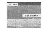
太陽電池において選択エミッタ方式(例えば、エミッタは、金属コンタクトの下方の領域のドープ濃度が非常に高く、当該太陽電池内の他の領域のドープ濃度は中程度から高程度である)は、選択エミッタ構造を持たない従来の太陽電池に比べると、太陽電池の金属コンタクトと、P型またはN型のドープ領域との間の導電性を、太陽電池内の他の領域の光吸収率を劣化させることなく、改善するので、望ましい方式である。このような選択エミッタ方式によれば通常、太陽電池からの電流抽出が高くなることによって太陽電池の発電効率が高くなり、太陽光によって得られる電力のコストが低減する。例えば、図1に示す従来の太陽電池100は、P型シリコン基板110(例えば、P型シリコンから成るウェハ、帯状部材、薄膜、等)を利用しており、通常は、その上面にN+型ドープシリコン層120を含み、その背面にP+型ドープ領域115を含む。従来の太陽電池100はさらに、コンタクト130a−cと、ドープされたシリコン層120上の反射防止コーティング140と、背面コンタクト145を備える。しかし、このような従来の太陽電池では、N+型ドープシリコン120とメタライゼーションコンタクト130a−cとの間の接触抵抗が非常に高いので、電流抽出および電力変換効率が限定されてしまう。原理的には、接触抵抗を改善するためにドープシリコン層120のドープレベルを高くすることは、有益なことのように思えるが、金属コンタクトによって被覆されていない領域において高濃度ドープN++層に起因して、太陽光のうち特にUV帯域および青色帯域において、光吸収率が高くなると、光吸収時に基板110で生成される電荷キャリアの量が少なくなってしまい、太陽電池の電力変換効率が低くなってしまう。
In a solar cell, a selective emitter system (for example, the emitter has a very high doping concentration in the region below the metal contact and the doping concentration in other regions in the solar cell is moderate to high). Compared to the conventional solar cell without structure, the conductivity between the metal contact of the solar cell and the P-type or N-type doped region deteriorates the light absorption rate of other regions in the solar cell. This is a desirable method because it improves. According to such a selective emitter method, the power generation efficiency of the solar cell is usually increased by increasing the current extraction from the solar cell, and the cost of the electric power obtained by sunlight is reduced. For example, the conventional
このような課題に対処するべく、図2に示すような、選択エミッタ型の太陽電池200を利用するとしてよい。選択エミッタ型の太陽電池200は一般的に、真性半導体基板またはP型ドープ基板210と、P+型領域215とを備える。N+型ドープシリコン層220は、基板210上に形成されている。選択エミッタ型太陽電池200では、ドープシリコン層220は、N++型領域225a−c(層220のうち金属コンタクトで被覆されていない領域よりも、N型ドーパント濃度が高い)を、ドープシリコン層220上に形成されている1以上のコンタクト230a−cの下方および隣りに有している。図1に示す従来の太陽電池100と同様に、選択エミッタ型太陽電池200は、背面コンタクト245と、反射防止コーティング240とを備える。選択エミッタ構造によって、光吸収を大幅に劣化させることなく、接触抵抗を改善する。この結果、電力変換効率が高くなる。
In order to cope with such a problem, a selective emitter type
図2に示すドープシリコンナノ粒子インクから形成される選択エミッタ型太陽電池を含むN+/P/P+型の太陽電池200については、図1に示す全面エミッタを持つ(例えば、エミッタは太陽電池の表面全体でドーパント濃度が均一である)従来の太陽電池100と比較した場合に、発電効率が絶対的に増加する(例えば、約1%から2%)ことが報告されている。このような発電効率の増加は大きな利点となるが、シリコンナノ粒子は、熱アニーリングまたはレーザ照射が行なわれる場合に、焼結特性および形状特性が悪いことが知られている。このように焼結特性および形状特性が低いと、形成される膜が多孔性および/または粗くなることが多い。粗い膜および/または多孔性の膜は、この後に太陽電池の表面およびシリコン基板の上部にドープシリコンエミッタと接触させつつ成膜する層(例えば、反射防止コーティング、表面パッシベーション等)の品質に悪影響を及ぼす。この結果、シリコンナノ粒子のみから形成した膜の品質では、ドープシリコンエミッタを持つ太陽電池が実現可能な最大発電効率が実現されない場合がある。
The N + / P / P + type
本発明の側面は、エピタキシャル構造、エピタキシャル構造の形成方法、および、このようなエピタキシャル構造を利用するデバイスに関する。本発明に係るエピタキシャル構造((ポリ)シラン、(ポリ)ゲルマン、および/または、(ポリ)ゲルマシランを含む、液相の第4A族半導体元素のインクから形成されるとしてよい)は、このようなインクを利用することによって、テクスチャ(平滑性)、密度、コンフォーマル性、接着性、導電性、および、純度に関して、第4A族半導体元素ナノ粒子系インクから形成される同様の膜に比べると、比較的質の高い膜が形成されるという利点があるとしてよい。図3Aおよび図3Bは、(ポリ)シラン系インクおよびシリコンナノ粒子系インクで形成した硬化シリコン薄膜を比較する電子顕微鏡断面走査結果を示す。具体的には、図3Aに示すように、(ポリ)シラン系インクから形成される膜は、シリコンナノ粒子系インクから形成した膜(例えば、図3Bの膜を参照のこと)と比べて相対的に、高密度且つ円滑である。シリコンナノ粒子系インクを利用する場合、ナノ粒子は粒径分布が広く、焼結時に常に完全に高密度化するわけではないので、形成される膜は比較的粗く多孔質であると考えられている。さらに、シリコンナノ粒子は、表面酸化物を持ち、焼結特性が低い。これらは、いずれか1つでも、多孔性で、および/または、粗い膜が形成される原因になるとしてよい。さらに、ナノ粒子インクを生成するためには、シリコンナノ粒子の表面改質が必要になるとしてよく、シリコンナノ粒子インクを生成するための分散剤を含むとしてよい。いずれか一方の処理によって、後に形成される膜に不純物を導入することができ、これによってさらに、硬化時の高密度化が制限され、膜の電気特性に影響を及ぼす。 Aspects of the present invention relate to an epitaxial structure, a method for forming an epitaxial structure, and a device using such an epitaxial structure. The epitaxial structure according to the present invention (which may be formed from a liquid phase Group 4A semiconductor element ink comprising (poly) silane, (poly) germane and / or (poly) germanesilane) is By utilizing the ink, in terms of texture (smoothness), density, conformality, adhesion, conductivity, and purity, compared to similar films formed from Group 4A semiconductor element nanoparticle-based inks, There may be an advantage that a relatively high quality film is formed. 3A and 3B show electron microscope cross-sectional scanning results comparing hardened silicon thin films formed with (poly) silane-based inks and silicon nanoparticle-based inks. Specifically, as shown in FIG. 3A, the film formed from the (poly) silane-based ink is relative to the film formed from the silicon nanoparticle-based ink (see, for example, the film in FIG. 3B). In particular, it is dense and smooth. When using silicon nanoparticle-based inks, nanoparticles are considered to be relatively coarse and porous because the nanoparticles have a wide particle size distribution and do not always become fully densified during sintering. Yes. Furthermore, silicon nanoparticles have a surface oxide and low sintering characteristics. Any one of these may cause the formation of a porous and / or rough film. Furthermore, in order to produce a nanoparticle ink, it may be necessary to modify the surface of the silicon nanoparticles and may include a dispersant for producing the silicon nanoparticle ink. By either one of the treatments, impurities can be introduced into a film to be formed later, which further restricts densification during curing and affects the electrical properties of the film.
液相の第4A族半導体元素のインク(例えば、((ポリ)シラン、(ポリ)ゲルマン、および/または、(ポリ)ゲルマシランを含むインク)は通常、コーティングまたは印刷して硬化させると、従来の堆積膜(例えば、化学気相成長(CVD)法、物理気相成長(PVD)法、原子層堆積(ALD)法等で堆積する膜)と同様の特性を持つ膜(またはフィーチャ)を形成する。この膜は、例えば、第4A族半導体元素ナノ粒子系インクから得られる膜に比べて、多孔性が低くなっており(例えば、微小孔がほとんどまたは全くない)、平滑性が改善されているとしてよい。(ポリ)シラン、(ポリ)ゲルマン、および/または、(ポリ)ゲルマシランを含むインクを利用して作成された選択エミッタを含むデバイスまたは電池は、シリコン源としてシリコンナノ粒子のみを含むインクから形成される全面エミッタを含むデバイスまたは電池(例えば、図1に示すもの)および/または選択エミッタを含むデバイスまたは電池(例えば、図2に示すもの)に比べると、膜の品質が改善されたので電力変換効率が改善されているとしてよい。 Liquid phase Group 4A semiconductor element inks (eg, inks containing ((poly) silane, (poly) germane, and / or (poly) germanesilane)) are typically coated and printed and cured, A film (or feature) having characteristics similar to those of a deposited film (for example, a film deposited by a chemical vapor deposition (CVD) method, a physical vapor deposition (PVD) method, an atomic layer deposition (ALD) method, or the like) is formed. This film has lower porosity (eg, few or no micropores) and improved smoothness compared to, for example, a film obtained from a Group 4A semiconductor element nanoparticle-based ink. A device or battery comprising a selective emitter made utilizing an ink comprising (poly) silane, (poly) germane, and / or (poly) germanesilane is silicon. As compared to a device or battery (eg, as shown in FIG. 1) and / or a device or battery (eg, as shown in FIG. 2) containing a full emitter formed from an ink containing only silicon nanoparticles as Since the film quality is improved, the power conversion efficiency may be improved.
さらに、シクロシランおよび/またはシクロ(ポリ)シランを含む液相の第4A族半導体元素のインクを用いると、洗浄済みまたはエッチング済みの(多)結晶性表面を持つ基板に成膜して硬化させることによって、エピタキシャル膜またはエピタキシャルフィーチャが形成される。エピタキシャル膜またはエピタキシャルフィーチャは、コンタクト(例えば、オーミックコンタクト、コレクタコンタクト、ソース/ドレインコンタクト、選択エミッタ等)、そして、アナログデバイス、ミクストシグナルデバイスおよびCMOSデバイス、ならびに/または、ダイオード、太陽電池、MOSFETデバイス、SOIデバイス、バイポーラトランジスタおよび/または薄膜トランジスタ等のデバイスにおけるウェル等の構造を形成するために用いることができる。このような構造および/またはデバイスは、本発明に係るエピタキシャル膜またはエピタキシャルフィーチャが、(例えば、インクをコーティングおよび/または印刷する方法を採用することによって、従来の真空エピタキシャル成長工程およびフォトリソグラフィーパターニング工程に比べて)大幅にコストを削減しつつ、エピタキシャル膜またはエピタキシャルフィーチャと、この膜またはフィーチャが接触する材料(例えば、基板)との間の領域において略完璧な界面を形成するので、太陽光発電デバイス、光センサデバイス、画像センサデバイス、発光デバイス、MEMSデバイス、表示デバイス、センサデバイス等のデバイスで、特に有用性が高くなるとしてよい。基板上にエピタキシャル成長させる層またはフィーチャは、第4A族半導体元素ナノ粒子系インクでは、ナノ粒子のナノ結晶性のために、形成することができない。この結果、多数の表面欠陥が発生し、結晶相および/または結晶方位にバラツキが発生してしまい、上述したように、堆積させた膜において結晶方位のバラツキが大きくなり、上述したように典型的な焼結挙動の劣化が見られる。この結果、第4A族ナノ粒子系インクで形成する膜は、高品質のエピタキシャル膜、エピタキシャル層、および/または、エピタキシャルフィーチャの形成に関して制限が課されると考えられるので、当該膜と、当該膜が接触する材料または基板との間の界面の品質に応じて決まる電力変換効率および接触抵抗等の特性が改善されることにつながり得る。 Further, when a liquid phase Group 4A semiconductor element ink containing cyclosilane and / or cyclo (poly) silane is used, the ink is deposited and cured on a cleaned or etched (poly) crystalline surface substrate. Forms an epitaxial film or feature. Epitaxial films or epitaxial features include contacts (eg, ohmic contacts, collector contacts, source / drain contacts, selective emitters, etc.) and analog devices, mixed signal devices and CMOS devices, and / or diodes, solar cells, MOSFET devices. It can be used to form structures such as wells in devices such as SOI devices, bipolar transistors and / or thin film transistors. Such structures and / or devices allow the epitaxial film or epitaxial features of the present invention to be used in conventional vacuum epitaxial growth processes and photolithography patterning processes (eg, by employing a method of coating and / or printing ink). A photovoltaic device since it creates a substantially perfect interface in the region between the epitaxial film or epitaxial feature and the material (e.g., substrate) that the film or feature contacts, while significantly reducing costs) In particular, it may be highly useful in devices such as optical sensor devices, image sensor devices, light emitting devices, MEMS devices, display devices, and sensor devices. Layers or features that are epitaxially grown on the substrate cannot be formed in Group 4A semiconductor element nanoparticle-based inks due to the nanocrystalline nature of the nanoparticles. As a result, a large number of surface defects occur, and the crystal phase and / or crystal orientation varies. As described above, the crystal orientation varies in the deposited film. Deterioration of sintering behavior is observed. As a result, the film formed with the Group 4A nanoparticle-based ink is considered to be restricted with respect to the formation of high quality epitaxial films, epitaxial layers, and / or epitaxial features, so the film and the film This can lead to improvements in properties such as power conversion efficiency and contact resistance that depend on the quality of the interface between the material and the substrate in contact with the substrate.
本発明の実施形態は、エピタキシャル構造を形成する方法に関し、当該方法は、(a)基板の表面を洗浄またはエッチングして、結晶性材料、多結晶性材料、または、微晶性材料を露出させる段階と、(b)印刷またはコーティングによって、露出させた結晶性材料、多結晶性材料または微晶性材料に、(ポリ)シラン、(ポリ)ゲルマン、および/または、(ポリ)ゲルマシランを含む液相インクを堆積させる段階と、(c)基板および堆積させた(ポリ)シラン、(ポリ)ゲルマン、および/または、(ポリ)ゲルマシランを、(ポリ)シラン、(ポリ)ゲルマン、および/または、(ポリ)ゲルマシランで形成する膜またはフィーチャが、露出した材料の結晶構造を持つために十分な温度および時間にわたって加熱する段階とを備える。多くの場合、基板上で露出した材料の結晶構造を取るように加熱される(ポリ)シラン、(ポリ)ゲルマン、および/または、(ポリ)ゲルマシランは、インクに含まれる(ポリ)シラン、(ポリ)ゲルマン、および/または、(ポリ)ゲルマシランと全く同じものではないとしてよい。例えば、成膜中または成膜直後にインクが露光(例えば、UV光で)される場合、(ポリ)シラン、(ポリ)ゲルマン、および/または、(ポリ)ゲルマシランは、分子量および/または粘度が高くなるか、架橋されるか、または、化学的特性および/または物理的特性に他の点で相違が見られるとしてよい。 Embodiments of the present invention relate to a method of forming an epitaxial structure, the method comprising: (a) cleaning or etching a surface of a substrate to expose a crystalline material, a polycrystalline material, or a microcrystalline material. And (b) a liquid containing (poly) silane, (poly) germane, and / or (poly) germane silane in a crystalline, polycrystalline or microcrystalline material exposed by printing or coating. Depositing the phase ink; (c) the substrate and the deposited (poly) silane, (poly) germane, and / or (poly) germanilan, (poly) silane, (poly) germane, and / or Heating the film or feature formed of (poly) germsilane for a temperature and for a time sufficient to have a crystalline structure of the exposed material.In many cases, (poly) silane, (poly) germane, and / or (poly) germane silane that is heated to take the crystalline structure of the exposed material on the substrate is (poly) silane, ( It may not be exactly the same as (poly) germane and / or (poly) germasilane. For example, when the ink is exposed (eg, with UV light) during or immediately after film formation, (poly) silane, (poly) germane, and / or (poly) germane silane has a molecular weight and / or viscosity. It may be elevated, cross-linked, or there may be other differences in chemical and / or physical properties.
本発明の他の実施形態は、(a)結晶性材料、多結晶性材料、または、微晶性材料が(例えば、上方に材料が無く)露出している表面を有する基板と、(b)露出している結晶性材料、多結晶性材料、または、微晶性材料上に設けられており第4A族半導体元素を含み、(i)露出している材料の結晶構造および(ii)第1のドープ領域を有する膜またはフィーチャと、(c)膜またはフィーチャの第1のドープ領域上に設けられている1以上のコンタクトとを備える構造に関する。一部の実施形態例によると、第4A族半導体元素は、シリコンおよび/またはゲルマニウムを含む。 Other embodiments of the invention include: (a) a substrate having a surface on which a crystalline, polycrystalline, or microcrystalline material is exposed (eg, no material above); and (b) An exposed crystalline material, a polycrystalline material, or a microcrystalline material and comprising a Group 4A semiconductor element, (i) a crystal structure of the exposed material and (ii) a first And (c) a structure comprising one or more contacts provided on a first doped region of the film or feature. According to some example embodiments, the Group 4A semiconductor element comprises silicon and / or germanium.
本発明の別の実施形態は、(a)結晶性材料、多結晶性材料、または、微晶性材料が露出している表面を有する基板と、(b)露出している結晶性材料、多結晶性材料、または、微晶性材料上に設けられており第4A族半導体元素を含み、露出している材料の結晶構造を持ち、(ポリ)シラン、(ポリ)ゲルマン、および/または、(ポリ)ゲルマシランを含む液相インクで形成されている膜またはフィーチャとを備える構造に関する。 Another embodiment of the present invention includes: (a) a crystalline material, a polycrystalline material, or a substrate having a surface on which a microcrystalline material is exposed; and (b) an exposed crystalline material, A crystalline material or a microcrystalline material, including a Group 4A semiconductor element, having an exposed material crystal structure, (poly) silane, (poly) germane, and / or ( It relates to a structure comprising a film or a feature formed of a liquid phase ink comprising poly) germsilane.
本発明は、エピタキシャル構造、エピタキシャル構造を形成する方法、および、エピタキシャル構造を備えるデバイスを提供する。本明細書で説明する構造および方法は、(ポリ)シラン、(ポリ)ゲルマン、および/または、(ポリ)ゲルマシランを含む液相半導体インクから得られる膜であって、平滑性、密度、コンフォーマル性、純度、電気特性および/または多孔性に関して、(ポリ)シラン、(ポリ)ゲルマン、および/または、(ポリ)ゲルマシランを含まず、シリコンおよび/またはゲルマニウムの唯一の供給源として同じ第4A族半導体元素のナノ粒子を含むインクで、同一条件下、同一プロセスで、形成される膜に比べると、一般的に非常に高品質の膜を利用している。この結果、本明細書で説明している方法および構造は、膜の品質および/またはエピタキシャル膜の形成が改善されたことにより、特性(例えば、(ポリ)シラン、(ポリ)ゲルマンおよび/または(ポリ)ゲルマシランを含むドープされた第4族半導体元素前駆体インクを印刷することで得られる選択エミッタ構造を利用した太陽電池の電力変換効率)が改善されたデバイス(例えば、太陽光発電デバイス、太陽電池、光センサ、画像センサ、発光デバイス、MEMSデバイス、アナログデバイスまたはバイポーラデバイス等)を、高真空成膜設備およびフォトリソグラフィーパターニング工程に関するコストではなく、インクをコーティングまたは印刷するコスト(例えば、コスト低減)で、提供できるという利点を持つとしてよい。 The present invention provides an epitaxial structure, a method of forming an epitaxial structure, and a device comprising the epitaxial structure. The structures and methods described herein are films obtained from liquid phase semiconductor inks comprising (poly) silane, (poly) germane, and / or (poly) germanesilane, which are smooth, density, conformal Group 4A as a sole source of silicon and / or germanium, free of (poly) silane, (poly) germane, and / or (poly) germanisilane, in terms of properties, purity, electrical properties and / or porosity An ink containing semiconductor element nanoparticles generally uses an extremely high quality film as compared to a film formed under the same process and in the same process. As a result, the methods and structures described herein can be characterized by improved film quality and / or improved epitaxial film formation (eg, (poly) silane, (poly) germane and / or ( Devices with improved solar cell power conversion efficiencies using selective emitter structures obtained by printing doped Group 4 semiconductor element precursor inks containing poly) germsilane (eg, photovoltaic devices, solar The cost of coating or printing a battery, photosensor, image sensor, light emitting device, MEMS device, analog device or bipolar device, etc., rather than the costs associated with high vacuum deposition facilities and photolithography patterning processes (eg, cost reduction) ), It may have the advantage that it can be provided.
本発明の上記およびその他の利点は、以下に記載する好ましい実施形態の詳細な説明から容易に明らかになるであろう。 These and other advantages of the present invention will be readily apparent from the detailed description of the preferred embodiments set forth below.
以下では、本発明のさまざまな実施形態を詳細に説明する。本発明を以下の好ましい実施形態に関連付けて説明しているが、以下の説明は本発明をそれらの実施形態に限定するものではないと理解されたい。逆に、本発明は、請求項で定義される本発明の意図および範囲内に含まれる代替例、変形例および均等例を含むものとする。さらに、以下の詳細な説明では、本発明を完全に理解していただくべく、数多く具体的且つ詳細な内容を記載している。しかし、本発明は以下に記載する具体的且つ詳細な内容を採用することなく実施し得ることは当業者には容易にわかることである。また、公知の方法、手順、構成要素および回路は、本発明の側面を不要にあいまいにすることを避けるべく、詳細な説明を省略する。 In the following, various embodiments of the present invention will be described in detail. While the invention has been described in connection with the following preferred embodiments, it is to be understood that the following description is not intended to limit the invention to those embodiments. On the contrary, the invention is intended to cover alternatives, modifications, and equivalents included within the spirit and scope of the invention as defined by the claims. Furthermore, in the following detailed description, numerous specific details are set forth in order to provide a thorough understanding of the present invention. However, it will be readily apparent to those skilled in the art that the present invention may be practiced without employing the specific details described below. In other instances, well-known methods, procedures, components, and circuits have not been described in detail so as not to unnecessarily obscure aspects of the present invention.
本開示では、「堆積」という用語は、明確にそうでない旨が文脈から推定される場合を除き、全面堆積、コーティングおよび印刷を含む全ての形態の堆積を含むものとする。基板に金属膜をコーティングまたは印刷する方法のさまざまな実施形態では、コーティングまたは印刷は、インクジェット、グラビア印刷、スクリーン印刷、オフセット印刷またはフレキソ印刷、スプレーコーティング、スピンコーティング、スリットコーティング、押し出しコーティング、ディップコーティング、メニスカスコーティング、マイクロスポッティング、および/または、ペンコーティングといった方式を利用して基板に材料を塗布することを含むとしてよい。さらに、特定の材料については、「から実質的に成る」という表現は、意図的に添加されたドーパントを除外するものではなく、特定の所望の(そして非常に異なる)物理的特性および/または電気的特性を付与するドーパントが添加された材料(または、この材料で形成した素子または構造)を意味するとしてよい。 In this disclosure, the term “deposition” is intended to include all forms of deposition, including full surface deposition, coating and printing, unless explicitly inferred from the context. In various embodiments of methods of coating or printing a metal film on a substrate, the coating or printing is ink jet, gravure printing, screen printing, offset printing or flexographic printing, spray coating, spin coating, slit coating, extrusion coating, dip coating. , Applying material to the substrate using methods such as meniscus coating, micro spotting, and / or pen coating. Furthermore, for a particular material, the expression “consisting essentially of” does not exclude intentionally added dopants, but rather specific desired (and very different) physical properties and / or electrical properties. It may mean a material (or an element or a structure formed from this material) to which a dopant that imparts mechanical characteristics is added.
「シラン」という用語は、(1)シリコンおよび/またはゲルマニウム、および(2)水素を、主に含む、または、(1)および(2)から実質的に成る化合物または複数の化合物の混合物を意味する。そして、「ポリシラン」という用語は、少なくとも15個のシリコンおよび/またはゲルマニウムの原子を持つ種を主に含む一のシランまたは複数のシランの混合物を意味する。「(ポリ)シラン」という用語は、シラン、ポリシラン、または、この両方である化合物または化合物群を意味する。このような(ポリ)シラン(つまり、シランおよび/またはポリシラン)は、特定用途の所与の組成の特性に大きな悪影響を及ぼさない所定量または所定原子濃度のハロゲン原子(Cl等)および1以上の環状リングを含むとしてよい。「(シクロ)アルカン」という用語は、実質的に炭素および水素から成り、直鎖状、分岐状、または、環状の構造を持つ化合物または複数の化合物の混合物を意味する。「(シクロ)シラン」という用語は、(1)シリコンおよび/またはゲルマニウム、および、(2)水素を主に含む、または、(1)および(2)から実質的に成る化合物または化合物の混合物であって、1以上の環状リングを含み、一般的に15個未満のシリコンおよび/またはゲルマニウムの原子を含む化合物または化合物の混合物を意味する。「ヘテロ(シクロ)シラン」および「ヘテロ(ポリ)シラン」という用語は、(1)シリコンおよび/またはゲルマニウム、(2)水素、および、(3)従来の炭化水素置換基、シリル置換基、または、ゲルミル置換基によって置換され、1以上の環状リングまたは少なくとも15個のシリコンおよび/またはゲルマニウムの原子を含むB、P、AsまたはSb等の1以上のドーパント原子、から実質的に成る化合物または化合物の混合物を意味する。 The term “silane” means a compound or mixture of compounds comprising (1) silicon and / or germanium, and (2) mainly hydrogen or consisting essentially of (1) and (2) To do. The term “polysilane” means a silane or a mixture of silanes mainly comprising species having at least 15 silicon and / or germanium atoms. The term “(poly) silane” means a compound or group of compounds that are silane, polysilane, or both. Such (poly) silanes (ie, silanes and / or polysilanes) are a predetermined amount or a predetermined atomic concentration of halogen atoms (such as Cl) and one or more that do not significantly adversely affect the properties of a given composition for a particular application An annular ring may be included. The term “(cyclo) alkane” means a compound or mixture of compounds consisting essentially of carbon and hydrogen and having a linear, branched, or cyclic structure. The term “(cyclo) silane” refers to a compound or mixture of compounds comprising (1) silicon and / or germanium and (2) mainly comprising or consisting essentially of (1) and (2) It means a compound or mixture of compounds comprising one or more ring rings and generally containing less than 15 silicon and / or germanium atoms. The terms “hetero (cyclo) silane” and “hetero (poly) silane” refer to (1) silicon and / or germanium, (2) hydrogen, and (3) conventional hydrocarbon substituents, silyl substituents, or A compound or compound consisting essentially of one or more cyclic rings or one or more dopant atoms, such as B, P, As or Sb, substituted by a germyl substituent and containing at least 15 silicon and / or germanium atoms Means a mixture of
「液相」という表現は通常、単体または組み合わせた状態で、外囲温度(例えば、約摂氏15度から約摂氏25度)で液相にある1以上の材料を示す。「ドープシラン」という用語は、(1)第4A族原子材料(通常は、1以上の第4A族半導体元素(例えば、Siおよび/またはGe)と、水素とから成る)、および、(2)ドーパント材料(通常は、1以上の共有結合されている一価または二価の炭化水素置換基またはシラン置換基を含むB、P、AsまたはSb等の1以上の従来の半導体ドーパント原子から実質的に成る)を含む組成を意味する。そして、ヘテロ(シクロ)シランあるいはヘテロ(ポリ)シラン等の一の種、または、(ポリ)シラン、および、オルガノシリルホスフィンまたはシリルホスフィンまたはシリルホスフィンボラン等、複数の種を含むとしてよい。 The expression “liquid phase” typically refers to one or more materials that are in the liquid phase at ambient temperature (eg, from about 15 degrees Celsius to about 25 degrees Celsius), either alone or in combination. The term “doped silane” refers to (1) a Group 4A atomic material (usually composed of one or more Group 4A semiconductor elements (eg, Si and / or Ge) and hydrogen), and (2) a dopant. Material (usually substantially from one or more conventional semiconductor dopant atoms such as B, P, As or Sb, including one or more covalently bonded mono- or divalent hydrocarbon substituents or silane substituents. Composition). One species such as hetero (cyclo) silane or hetero (poly) silane, or (poly) silane and a plurality of species such as organosilylphosphine, silylphosphine, or silylphosphineborane may be included.
説明を簡略化する便宜上、「結合」、「接続」、「連通」といった用語は、明らかに文脈からそうでないとわかる場合を除いて、直接的または間接的な結合、接続、または、連通を意味するものとする。これらの用語は、本明細書では概して同様の意味を持つ用語として利用されるが、通常は関連技術分野で認められている意味を持つ。さらに、「結晶性」、「多結晶性」および「微晶性」といった用語は、同様の意味を持つ用語として利用されるとしてよいが、通常は関連技術分野で認められている意味を持つ。「(半)導体」、「(半)導性」といった用語は、伝導性および/または半導性を持つ材料、前駆体、層、フィーチャ、または、その他の種あるいは構造を意味する。また、説明を簡略化する便宜上、「一部」、「部分」、および、「領域」といった用語は、互いに同様の意味を持つものとして利用されるとしてよいが、通常は関連技術分野で認められている意味を持つ。また、本明細書で利用される場合、文脈からそうでないとわかる場合を除いては、「公知」、「所与」、「特定」および「所定」といった用語は通常、理論上は可変であるものの、通常は事前に設定され、利用中は変化しない値、量、パラメータ、制約、条件、状態、プロセス、手順、方法、実施、または、これらの組み合わせを意味する。 For the sake of simplicity, the terms “coupled”, “connected”, “communication” mean direct, indirect coupling, connection, or communication, unless the context clearly indicates otherwise. It shall be. These terms are generally used herein as terms having similar meanings, but usually have the meanings recognized in the related art. Furthermore, the terms “crystalline”, “polycrystalline” and “microcrystalline” may be used as terms having similar meanings, but usually have the meanings recognized in the related technical field. The terms “(semi) conductor”, “(semi) conductive” mean a material, precursor, layer, feature, or other species or structure that is conductive and / or semiconductive. For the sake of simplicity, terms such as “part”, “part”, and “region” may be used as having the same meaning as each other, but are generally recognized in the related technical field. Has a meaning. Also, as used herein, the terms “known”, “given”, “specific” and “predetermined” are usually variable in theory, unless the context indicates otherwise. However, it usually means a value, quantity, parameter, constraint, condition, state, process, procedure, method, implementation, or combination thereof that is preset and does not change during use.
本発明は、さまざまな側面から、実施形態例に基づき以下でさらに詳細に説明される。 The invention is explained in more detail below on the basis of exemplary embodiments from various aspects.
<エピタキシャル構造を形成方法の例>
本発明の第1の側面は、エピタキシャル構造を形成する方法に関する。当該方法は概して、基板の表面を洗浄またはエッチングすることを含む。洗浄またはエッチングを行った後、基板の表面には通常、結晶性材料、多結晶性材料、または、微晶性材料が露出している。基板の表面を洗浄またはエッチングした後、当該方法はさらに、(ポリ)シラン、(ポリ)ゲルマン、および/または、(ポリ)ゲルマシランを含む液相インクを、基板表面に露出している結晶性材料、多結晶性材料、または、微晶性材料に、(例えば、印刷またはコーティングによって)堆積させることを含む。基板および(ポリ)シラン、(ポリ)ゲルマン、および/または、(ポリ)ゲルマシランはこの後、(ポリ)シラン、(ポリ)ゲルマン、および/または、(ポリ)ゲルマシランで形成される膜またはフィーチャが、基板表面で結晶性材料、多結晶性材料、または、微晶性材料の結晶構造を取るのに十分な時間および温度にわたって、加熱される。
<Example of method for forming epitaxial structure>
The first aspect of the present invention relates to a method of forming an epitaxial structure. The method generally includes cleaning or etching the surface of the substrate. After cleaning or etching, a crystalline material, a polycrystalline material, or a microcrystalline material is usually exposed on the surface of the substrate. After cleaning or etching the surface of the substrate, the method further includes a crystalline material exposing a liquid phase ink comprising (poly) silane, (poly) germane, and / or (poly) germanesilane to the substrate surface Depositing (eg, by printing or coating) on a polycrystalline or microcrystalline material. The substrate and the (poly) silane, (poly) germane, and / or (poly) germane silane are then subjected to a film or feature formed of (poly) silane, (poly) germane, and / or (poly) germane silane. And heated for a time and temperature sufficient to take the crystalline structure of the crystalline, polycrystalline or microcrystalline material at the substrate surface.
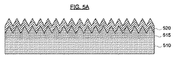
本発明の実施形態に応じて形成された構造の例を図4Aから図4Dに示す。図4Aを参照して説明すると、概して、基板400は、任意の適切な、電気的に活性で、および/または、機械的な支持力を持つ構造を含む。基板400の表面405は、結晶性材料、多結晶性材料または微晶性材料が部分的または完全に露出している。適切な、電気的に不活性の、または、不活性の基板には、ガラス、セラミック、誘電体および/またはプラスチック製のプレート、ディスク、シートおよび/または箔が含まれるとしてよい。これに代えて、適切な電気的に(半)導性の基板には、半導体(例えば、シリコン)および/または金属製のウェハ、ディスク、シートおよび/または箔が含まれるとしてよい。一部の実施形態によると、基板は、シリコンウェハ、ガラスプレート、セラミックプレートまたはセラミックディスク、プラスチックシートまたはプラスチックディスク、金属箔、金属シートまたは金属ディスク、およびこれらを組み合わせた積層体または多層構造から成る群から選択される部材を含む。実施形態例によると、基板は、単結晶ウェハ、ポリクリスタルウェハ、マルチクリスタルウェハ、金属グレードウェハ、その上に形成するエピタキシャル膜またはエピタキシャルフィーチャと同一または異なる第4A族半導体素子から実質的に成る帯状部材を含む。他の実施形態によると、基板は、セラミック基板(例えば、(i)アルミナ、ベリリア、セリア、ジルコニア等の酸化物セラミック、(ii)または、炭化ホウ素、窒化ホウ素、グラファイト、または、シリコンおよび/またはアルミニウムの炭化物、窒化物および/またはホウ化物等の非酸化物セラミック、または(iii)酸窒化シリコン、シリコンオキシカーバイド、酸窒化シリコンアルミニウムまたはその他の複合セラミック等の酸化物/非酸化物混合セラミックから成るプレート、長尺状部材、ウェハまたはディスク)、または、多孔性シリコン基板を含む。一部の実施例では(例えば、基板の表面に、少なくとも部分的に結晶性の第4A族元素以外の材料を持つ実施例)、基板は、1以上の微晶性薄膜あるいは多結晶性薄膜、または、基板の表面に堆積させられている1以上のフィーチャ(例えば、少なくとも部分的に結晶性の第4A族元素を含む)を持つとしてよい。一部の実施例では、微晶性または多結晶性の薄膜またはフィーチャは、厚みが100μm未満であるとしてよく、より好ましくは、50μm未満であるとしてよい。
Examples of structures formed according to embodiments of the present invention are shown in FIGS. 4A-4D. Referring to FIG. 4A, in general, the
実施形態例によると、基板表面に露出している結晶性材料、多結晶性材料または微晶性材料は、(ポリ)シラン、(ポリ)ゲルマン、および/または、(ポリ)ゲルマシラン(つまり、「(ポリ)シランインク」)を含む液相インクを堆積させる前に、洗浄および/またはエッチングされる。構造の表面を洗浄またはエッチングすることによって、基板表面への(ポリ)シランインクの接着および/または湿潤に悪影響を与える、および/または、形成されているエピタキシャル構造のエピタキシャル成長または電子特性に悪影響を与える、任意の本来存在する酸化物、残留有機材料、粒子、および/または、他の汚染物質(例えば、金属等)を除去するとしてよい。 According to example embodiments, the crystalline, polycrystalline or microcrystalline material exposed on the substrate surface may be (poly) silane, (poly) germane, and / or (poly) germane silane (ie, “ Before depositing the liquid phase ink comprising (poly) silane ink "), it is cleaned and / or etched. Cleaning or etching the surface of the structure adversely affects the adhesion and / or wetting of the (poly) silane ink to the substrate surface and / or adversely affects the epitaxial growth or electronic properties of the formed epitaxial structure Any inherent oxides, residual organic materials, particles, and / or other contaminants (eg, metals, etc.) may be removed.
適切なエッチング技術には、ウェットエッチングプロセス(例えば、ウェット化学エッチング)またはドライエッチングプロセス(例えば、反応性イオンエッチング(RIE))が含まれるとしてよい。水性フッ化水素酸(NH3および/またはNH4Fでバッファーされるとしてもよい)、HF蒸気、HF:ピリジン、HBrおよびその他の関連技術分野で公知のエッチャント等の液体エッチャントまたは蒸気エッチャントを用いて基板表面をエッチングするとしてよい。これに代えて、基板表面は、関連技術分野で公知のように、スパッタリングエッチングまたはプラズマエッチングによって洗浄するとしてよい。 Suitable etching techniques may include wet etching processes (eg, wet chemical etching) or dry etching processes (eg, reactive ion etching (RIE)). Use liquid or vapor etchants such as aqueous hydrofluoric acid (which may be buffered with NH 3 and / or NH 4 F), HF vapor, HF: pyridine, HBr and other etchants known in the related art. The substrate surface may be etched. Alternatively, the substrate surface may be cleaned by sputtering etching or plasma etching, as is known in the related art.
例えば、一実施形態によると、基板は、基板を液相の洗浄剤および/または溶剤型洗浄剤(例えば、有機残留物を除去するもの)に浸漬させ、および/または、液相の洗浄剤および/または溶剤型洗浄剤で基板をリンスし、この後で、希釈酸性水溶液(例えば、アンモニアおよび/またはフッ化アンモニウムでバッファーされる希釈水溶性HF)を用いたウェットエッチングで洗浄される。これに代わるエッチングプロセスとしては、従来のピラニアエッチングがあり、これに代わって基板をウェットエッチングする際に用いる酸には、硝酸、硫酸、塩酸等が含まれる。これらは、利用する基板および基板に処理を行う温度に応じて選択される。別の実施形態では、スパッタリングエッチングを用いて基板を洗浄する。基板を洗浄するためにドライエッチングプロセスで利用されるガスの選択は、特に限定されるものではない。基板の表面から望ましくない汚染物質を略全て除去するが除去不可能な残留物は残さないものであれば、どのようなガスまたは混合ガスを利用するとしてもよい。例えば、基板のスパッタリング洗浄でアルゴン等の不活性ガスを利用するとしてよい。 For example, according to one embodiment, the substrate immerses the substrate in a liquid-phase cleaner and / or a solvent-based cleaner (eg, one that removes organic residues) and / or a liquid-phase cleaner and The substrate is rinsed with / or a solvent-type cleaning agent, and thereafter cleaned by wet etching using a dilute acidic aqueous solution (for example, dilute aqueous HF buffered with ammonia and / or ammonium fluoride). As an alternative etching process, there is a conventional piranha etching. Instead of this, the acid used when wet etching the substrate includes nitric acid, sulfuric acid, hydrochloric acid and the like. These are selected according to the substrate to be used and the temperature at which the substrate is processed. In another embodiment, the substrate is cleaned using sputtering etching. The selection of the gas used in the dry etching process for cleaning the substrate is not particularly limited. Any gas or mixed gas may be used as long as it removes substantially all undesirable contaminants from the surface of the substrate, but does not leave unremovable residues. For example, an inert gas such as argon may be used for sputtering cleaning of the substrate.
一部の実施形態によると、エッチングの前後で、基板を(例えば、純水で)リンスするとしてよい。その後、任意で、有機溶媒または有機溶媒混合物で浸漬および/リンスして、基板の表面に存在している不要な有機残留物を除去してさらに洗浄するとしてよい。これに代えて、基板をさらに洗浄する場合には、界面活性剤の懸濁液または水溶液で浸漬および/またはリンスする(この後で、純粋でリンスする)ことを含むとしてよい。基板をさらに洗浄するために用いられる適切な洗浄用溶媒は、米国特許出願第12/790,627号(出願日:2010年5月28日)(代理人整理番号:IDR3022)で詳細に説明されている。当該出願の内容は、参照により本願に組み込まれる。 According to some embodiments, the substrate may be rinsed (eg, with pure water) before and after etching. Thereafter, it may optionally be dipped and / or rinsed with an organic solvent or mixture of organic solvents to remove unwanted organic residues present on the surface of the substrate and further wash. Alternatively, further cleaning of the substrate may include immersing and / or rinsing with a surfactant suspension or solution (followed by a pure rinse). A suitable cleaning solvent used to further clean the substrate is described in detail in US patent application Ser. No. 12 / 790,627 (filing date: May 28, 2010) (Attorney Docket No. IDR3022). ing. The contents of that application are incorporated herein by reference.
図4Bを参照しつつ説明すると、基板を洗浄した後、第4A族半導体元素(例えば、Siおよび/またはGe)の前駆体である(ポリ)シラン、(ポリ)ゲルマン、および/または、(ポリ)ゲルマシランと、任意で溶媒とを含む液相インク410を、洗浄済みの基板表面に堆積させる。適切な液相のドープまたはノンドープの(ポリ)シラン、(ポリ)ゲルマン、および/または、(ポリ)ゲルマシランを含むインク、および、当該インクをコーティングおよび印刷する方法は、米国特許第7,314,513号、7,498,015号、7,674,926号、7,723,457号および7,879,696号で、同時係属中の米国特許出願第11/249,167号(出願日:2005年10月11日、代理人整理番号:IDR0423)、第11/543,414号(出願日:2006年10月5日、代理人整理番号:KOV−026)、第11/867,587号(出願日:2007年10月4日、代理人整理番号:IDR0884)、第12/114,741号(出願日:2008年5月2日、代理人整理番号:IDR1102)および第12/243,880号(出願日:2008年10月1日、代理人整理番号:IDR1574)で詳細に説明する。上記特許文献のうち関連個所は、参照により本願に組み込まれる。
Referring to FIG. 4B, after cleaning the substrate, a (poly) silane, (poly) germane, and / or (poly) silane that is a precursor of a Group 4A semiconductor element (eg, Si and / or Ge). ) A
実施形態例によると、(ポリ)シランインクは、1以上の直鎖状、分岐状、架橋型、環状または多環状の(ポリ)シラン、(ポリ)ゲルマン、または、(ポリ)シラゲルマン(以下では、「(ポリ)シラン」と総称する)を含む。例えば、(ポリ)シランは、ペルヒドロシラン、ペルヒドロゲルマン、ペルヒドロシラゲルマン、シクロシラン、シクロゲルマン、シクロシラゲルマン、ポリシラン、ポリゲルマン、ポリシラゲルマン、ヘテロ(ポリ)シラン、ヘテロ(ポリ)ゲルマン、ヘテロ(ポリ)シラゲルマン、および、これらの組み合わせまたは混合物等、1以上の化合物を含むとしてよい。シクロシランおよびポリシランは、ペルヒドロ化されるとしてよく、または、ハロゲンの量がインクの性質または結果として得られる膜またはフィーチャの特性に悪影響を与えない限りにおいて、ハロゲンをある程度まで含むとしてよい。一部の実施形態によると、(ポリ)シランインクは、さらに、シリコンおよび/またはゲルマニウムのナノ粒子を含むとしてよい。別の実施形態によると、(ポリ)シランインクはさらに、1以上のドーパント原子(例えば、P、B、Asおよび/またはSb)が組み込まれた化合物を含むとしてよい。 According to example embodiments, the (poly) silane ink comprises one or more linear, branched, cross-linked, cyclic or polycyclic (poly) silanes, (poly) germanes, or (poly) silagermans (below) , "Collectively referred to as" (poly) silane "). For example, (poly) silane is perhydrosilane, perhydrogermane, perhydrosilagerman, cyclosilane, cyclogermane, cyclosilagermane, polysilane, polygermane, polysilagermane, hetero (poly) silane, hetero (poly) germane, One or more compounds may be included such as hetero (poly) silagerman and combinations or mixtures thereof. Cyclosilanes and polysilanes may be perhydrolated or may contain some halogen, as long as the amount of halogen does not adversely affect the properties of the ink or the resulting film or feature. According to some embodiments, the (poly) silane ink may further comprise silicon and / or germanium nanoparticles. According to another embodiment, the (poly) silane ink may further comprise a compound incorporating one or more dopant atoms (eg, P, B, As and / or Sb).
具体的には、一部の実施例によると、(ポリ)シランは、AnH2n+2(例えば、SinH2n+2、これは、直鎖状、分岐状および/または架橋されているとしてよい)、シクロ−AmH2m(例えば、SimH2m)および/またはAnH2n−p(例えば、SinH2n−p、これは、分岐部分または架橋を含むとしてよく、1以上の環状リングを含む)で表される化合物を含むとしてよい。尚、AはSiおよび/またはGeであり、nは少なくとも3であり(例えば、3から1,000,000、10から1,000、15から250、または、3以上または15以上の任意のその他の範囲の値)、mは3から約20であり(例えば、5から8であり、または、当該範囲内の任意のその他の範囲の値)、pは0またはn以下の偶数の整数である。 Specifically, according to some embodiments, the (poly) silane is A n H 2n + 2 (eg, Si n H 2n + 2 , which may be linear, branched and / or cross-linked) , Cyclo-A m H 2m (eg, Si m H 2m ) and / or An H 2n-p (eg, Si n H 2n-p , which may include a branched moiety or a bridge, one or more cyclic A compound represented by (including a ring). Where A is Si and / or Ge and n is at least 3 (eg, 3 to 1,000,000, 10 to 1,000, 15 to 250, or any other 3 or more or 15 or more M is from 3 to about 20 (eg, from 5 to 8, or any other range value within the range), and p is an even integer less than or equal to 0 or n .
一部の実施形態によると、(ポリ)シラン化合物は、1以上の直鎖状、分岐状、架橋型、環状、または、多環状の、3個から20個のSiおよび/またはGeの原子を含む1以上の(シクロ)シランのポリマーまたはコポリマーを含む(または、さらに含む)としてよい。例えば、(シクロ)シランは、3個から12個のSiおよび/またはGeの原子を含むとしてよく、5個から8個のSiおよび/またはGeの原子を含むとしてよく、または、任意のその他の範囲のSiおよび/またはGeの原子を含むとしてよい。さまざまな例によると、(ポリ)シランは、−(−AkH2k−)−ユニット、または、−(c−AmH2m−2)−ユニット(「c」は環状ユニットを意味する)を繰り返すホモポリマー、−(−AkH2k−)−ユニット、および/または−(c−AmH2m−2)−ユニットの1以上のブロックを含む(各ブロックは、所与のブロックにこのようなユニットを1以上含む)ブロックコポリマー、または、当該ユニットのランダムコポリマーを含むとしてよい。上記のポリマーはいずれも、分岐状、架橋型、または、(ポリ)環状(例えば、自身に架橋または凝結されている)であり、kは、少なくとも1の整数であり(例えば、1、2、3、4、5以上、例えば、3−5等)、mは、上述したものと同じである。 According to some embodiments, the (poly) silane compound comprises one or more linear, branched, bridged, cyclic, or polycyclic 3 to 20 Si and / or Ge atoms. It may include (or further include) one or more (cyclo) silane polymers or copolymers. For example, a (cyclo) silane may contain 3 to 12 Si and / or Ge atoms, may contain 5 to 8 Si and / or Ge atoms, or any other A range of Si and / or Ge atoms may be included. According to various examples, (poly) silane, - (- A k H 2k -) - units, or, - (c-A m H 2m-2) - units ( "c" means annular unit) Comprising one or more blocks of homopolymers,-(-A k H 2k -)-units, and / or- (c-A m H 2m-2 ) -units, each block in a given block It may comprise a block copolymer containing one or more such units, or a random copolymer of such units. All of the above polymers are branched, crosslinked, or (poly) cyclic (eg, crosslinked or aggregated to themselves), and k is an integer of at least 1 (eg, 1, 2, 3, 4, 5 or more, for example, 3-5 etc.), m is the same as described above.
一部の変形例によると、(ポリ)シラン組成物は、例えば、20個、30個、40個、50個、100個、1000個またはそれ以上のシリコン原子を含む1以上の比較的高い分子量の(ポリ)シランを含む。このように分子量が高い(ポリ)シランでは、質量負荷に比例して(ポリ)シラン組成物の粘度が高くなるので、印刷用途(例えば、インクジェット)についての特性が改善される。比較的分子量が大きい(ポリ)シランの量は、さまざまであるとしてよく、通常は、粘度が約2cPから約100,000cP(例えば、約4cPから約50,000cP、約4cPから約10,000cP、約5cPから約5000cP、約5cPから約1000cP、または、当該範囲内の任意のその他の範囲の値)になるような量である。しかし、一部の例では、インクに含まれる(ポリ)シランの量は、約1重量%から約40重量%(例えば、インクの約1重量%から約20重量%であり、当該範囲内の任意のその他の範囲の値)の範囲内であるとしてよい。 According to some variations, the (poly) silane composition has one or more relatively high molecular weights including, for example, 20, 30, 40, 50, 100, 1000 or more silicon atoms. Of (poly) silane. In this way, (poly) silane having a high molecular weight increases the viscosity of the (poly) silane composition in proportion to the mass load, so that the characteristics for printing applications (for example, inkjet) are improved. The amount of (poly) silane having a relatively high molecular weight may vary, and typically has a viscosity of about 2 cP to about 100,000 cP (eg, about 4 cP to about 50,000 cP, about 4 cP to about 10,000 cP, From about 5 cP to about 5000 cP, from about 5 cP to about 1000 cP, or any other range of values within the range. However, in some examples, the amount of (poly) silane included in the ink is from about 1% to about 40% by weight (eg, from about 1% to about 20% by weight of the ink, It may be within the range of any other range value).
インク組成物が(ポリ)シランを含む場合、(ポリ)シランは、シリコン、ゲルマニウムおよび水素に関して原子純度が90%より高いとしてよい(つまり、(ポリ)シランに含まれる原子の90%を超える量がSi、GeまたはHである)。一例を挙げると、(ポリ)シランは、シリコンおよび水素に関して原子純度が90%より高い。このため、(ポリ)シランは、他の種(例えば、ホウ素、ガリウム、リン、ヒ素、アンチモン、ハロゲン(例えば、F、Cl、Br等)、炭素、酸素、窒素等)を最高で10原子濃度含むことができる。他の種は、所与の用途について(ポリ)シランから形成する膜またはフィーチャの電気的特性に大幅な悪影響を及ぼさない限りにおいて含められる。一の好ましい実施形態によると、原子純度は、99%より高い。 When the ink composition includes (poly) silane, the (poly) silane may have an atomic purity greater than 90% with respect to silicon, germanium, and hydrogen (ie, greater than 90% of the atoms contained in the (poly) silane) Is Si, Ge or H). As an example, (poly) silane has an atomic purity higher than 90% with respect to silicon and hydrogen. For this reason, (poly) silane has other species (for example, boron, gallium, phosphorus, arsenic, antimony, halogen (for example, F, Cl, Br, etc.), carbon, oxygen, nitrogen, etc.) at a concentration of up to 10 atoms. Can be included. Other species are included as long as they do not significantly adversely affect the electrical properties of the film or feature formed from (poly) silane for a given application. According to one preferred embodiment, the atomic purity is higher than 99%.
液相の(ポリ)シランインクはさらに、前駆体材料が溶解可能な溶媒を含むとしてよい。溶媒は、インク組成物の安定性を比較的高くし、不純物準位が低く、および/または、純化が容易であるものであってよく、有益な粘度および/または揮発性(例えば、インクジェットノズルの詰まりを予防し、印刷したインクが比較的低温および/または比較的短時間でも乾燥するのに十分な程度)を持ち、および/または、一般的にインク組成物から容易および/または完全に除去可能なものであってよい。実施形態例によると、溶媒は、摂氏30度から摂氏90度の温度でインクをプラテンに印刷した後、摂氏100度で10分間にわたって加熱することによって略完全に削除されるものである。例えば、溶媒は、1以上の炭化水素溶媒を含むとしてよく、例えば、アルカン、モノシクロアルカンまたはビシクロアルカン(例えば、シクロオクタン、デカリン、ジシクロペンタン等)、アルキル置換したモノシクロアルカンまたはビシクロアルカン、(環状)シロキサン、脂肪族アルコール(例えば、メタノール、エタノール、ブタノール、ヘキサノール、オクタノール、デカノール、ドデカノール、イコサノール、シクロヘキサノール、シクロオクタノール、テルピネオール、ボルネオール等のCl−C20アルコール)、および/またはフルオロアルカンを含むとしてよい。 The liquid phase (poly) silane ink may further include a solvent in which the precursor material can be dissolved. The solvent may be one that makes the ink composition relatively stable, has a low impurity level, and / or is easy to purify, and has a beneficial viscosity and / or volatility (eg, ink jet nozzles). Can prevent clogging, have a sufficient degree of printed ink to dry at a relatively low temperature and / or for a relatively short time) and / or can be easily and / or completely removed from the ink composition in general It may be anything. According to example embodiments, the solvent is substantially completely removed by printing the ink on the platen at a temperature of 30 to 90 degrees Celsius and then heating at 100 degrees Celsius for 10 minutes. For example, the solvent may include one or more hydrocarbon solvents, such as alkanes, monocycloalkanes or bicycloalkanes (eg, cyclooctane, decalin, dicyclopentane, etc.), alkyl substituted monocycloalkanes or bicycloalkanes, (Cyclic) siloxanes, aliphatic alcohols (eg, C 1 -C 20 alcohols such as methanol, ethanol, butanol, hexanol, octanol, decanol, dodecanol, icosanol, cyclohexanol, cyclooctanol, terpineol, borneol, etc.) and / or fluoro Alkanes may be included.
適切な溶媒は一般的に、外囲温度(例えば、摂氏15度から摂氏30度)で液体であるものが挙げられる。このため、溶媒は、C5−C12直鎖状および/または分岐状アルカンと、C6−C12モノシクロアルカンと、nをモノシクロアルカン連鎖での炭素原子の数とすると、1から2n個のC1−C4アルキル置換基あるいはハロゲン置換基、または、1からn個のC1−C4アルコキシル置換基で置換したC3−C8モノシクロアルカンと、pが0から4で、qが2から6(好ましくは、3から5)で、RおよびR´は、0から3個のC1−C4アルキル基(好ましくは、R´はメチル)で置換した独立したH、C1−C6アルキル、ベンジルまたはフェニルである場合に、(R3Si)(OSiR2)p(OSiR3)のシロキサンおよび(SiR´2O)qのシクロシロキサンと、mがフルオロアルカンに含まれる炭素原子の数である場合に、1から(2m+2)個のフッ素原子で置換され、外囲温度で液体であるC3−C8フルオロアルカンとから成る群から選択されるとしてよい。一実施例によると、溶媒は、C5−C10シクロアルカン(例えば、シクロヘキサン、シクロヘプタン、シクロオクタン、シス−デカリン等)を含む。別の実施例によると、溶媒は、最高で3個のC1−C4のアルキル基で置換された1以上のC5−C10モノシクロアルカンおよび/またはビシクロアルカンを含む。しかし、他の無極性および/または非極性の溶媒(例えば、C5−C12アルカン等の飽和炭化水素、ジ−C2−C6アルキルエーテル、メチルC4−C6アルキルエーテルおよびジ−C1−C4アルキルC2−C6アルキレンジエーテル(例えば、グリム)等の脂肪族エーテル、テトラヒドロフランおよびジオキサン等の環状エーテル、ベンゼン、トルエン、および、キシレン等のアレーン)が本発明に係る材料に含まれるとしてよい。
Suitable solvents generally include those that are liquid at ambient temperature (eg, 15 degrees Celsius to 30 degrees Celsius). Thus, the solvent is 1 to 2n, where C 5 -C 12 linear and / or branched alkanes, C 6 -C 12 monocycloalkanes, and n is the number of carbon atoms in the monocycloalkane chain. A C 1 -C 4 alkyl substituent or halogen substituent, or a C 3 -C 8 monocycloalkane substituted with 1 to n C 1 -C 4 alkoxyl substituents, and p is 0 to 4, q is 2 to 6 (preferably 3 to 5) and R and R ′ are independent H, C substituted with 0 to 3 C 1 -C 4 alkyl groups (preferably R ′ is methyl) 1 -C 6 alkyl, when benzyl or phenyl, in (R 3 Si) (OSiR 2 ) p (OSiR 3) of siloxane and (SiR' 2 O) and cyclosiloxanes q, m is fluoroalkane If the number of atom is substituted with from 1 to (2m + 2) number of fluorine atoms, it may be a selected from the group consisting of at ambient temperatures and C 3 -C 8 fluoroalkanes a liquid. According to one embodiment, the solvent,
一部の実施形態例によると、液相の(ポリ)シランインク(例えば、(ポリ)シランインク)は、高導電率のN+型および/またはP+型のシリコン膜またはシリコンフィーチャを形成するべく1以上のドーパント原子を含むとしてよい。例えば、液相のインクは、ホウ素、ガリウム、リン、ヒ素、または、アンチモン等の(例えば、1以上のオルガノホスフィン、オルガノボラン、シリルホスフィン、シリルボラン等)ドーパント源を、シリコン、ゲルマニウム、および、ドーパント元素の原子の総数に対して最高で約20原子濃度(または、約25−30原子濃度未満の任意の最大値)の量で含むとしてよい。一部の実施形態によると、ドーパント源は、DaR1 bの化学式を持つとしてよい。尚、aは1または2であり、bは3aであり、R1は、一例に過ぎないが、C1−C6アルキル、C6−C10アリル、C7−C10アラルキルまたはAR2 3であり、R2は水素またはAyH2y+1であり、AはSiまたはGeであり、1≦y≦4(好ましくはy=1)であり、R1のbの例は、独立してH、C1−C6アルキル、C6−C10アリル、C7−C10アラルキルまたはAR2 3である。さまざまな実施例によると、ドーパントは、D(AH3)3の化学式を持ち、DがPまたはBであり、AがSiまたはGeである。 According to some example embodiments, a liquid phase (poly) silane ink (eg, (poly) silane ink) is used to form a high conductivity N + type and / or P + type silicon film or feature. The above dopant atoms may be included. For example, liquid-phase inks may include boron, gallium, phosphorus, arsenic, or antimony (eg, one or more organophosphines, organoboranes, silylphosphines, silylboranes, etc.) dopant sources, silicon, germanium, and dopants. It may be included in an amount up to about 20 atomic concentration (or any maximum value less than about 25-30 atomic concentration) relative to the total number of atoms of the element. According to some embodiments, the dopant source may have a chemical formula of D a R 1 b . A is 1 or 2, b is 3a, and R 1 is merely an example, but C 1 -C 6 alkyl, C 6 -C 10 allyl, C 7 -C 10 aralkyl or AR 2 3 R 2 is hydrogen or A y H 2y + 1 , A is Si or Ge, 1 ≦ y ≦ 4 (preferably y = 1), and examples of b in R 1 are independently H C 1 -C 6 alkyl, C 6 -C 10 allyl, C 7 -C 10 aralkyl or AR 2 3 . According to various embodiments, the dopant has the formula D (AH 3 ) 3 , where D is P or B, and A is Si or Ge.
インク組成物は、最終的に形成される膜またはフィーチャにおいて所望のドープレベルを実現するために適切な割合の第4A族半導体元素の前駆体(例えば、(ポリ)シラン、(ポリ)ゲルマン、および/または、(ポリ)ゲルマシラン)およびドーパント源を含むとしてよい。例えば、インク組成物のうち、0.00001体積%から約20体積%(または、当該範囲内の任意の範囲の値、例えば、0.001体積%から10体積%)が実質的に、ドーパント源から成っているとしてよい。これに代えて、ドーパント源の量は、Siおよび/またはGe原子に関して約0.0001原子濃度から約10原子濃度(または、当該範囲内の任意の範囲の値)のドーパント原子が第4A族半導体元素の前駆体に含まれるようにするとしてよい。ドーパント前駆体、ドープシラン中間体、ドープシラン組成物、ドープ半導体前駆体インク、これらを用意する方法の例、および、前駆体インクおよび活性膜におけるドーパントレベルを決定および/または制御する技術については、米国特許第7,314,513号、第7,674,926号、および、第7,879,696号、ならびに、同時係属中の米国特許出願第11/249,167号(出願日:2005年10月11日、代理人整理番号:IDR0423)および第11/867,587号(出願日:2007年10月4日、代理人整理番号:IDR0884)にさらに詳細に記載されている。これらの特許文献の関連箇所は、参照により本願に組み込まれる。 The ink composition comprises a suitable proportion of a Group 4A semiconductor element precursor (e.g., (poly) silane, (poly) germane, and the like) to achieve the desired doping level in the final formed film or feature. (Or (poly) germasilane) and a dopant source. For example, 0.00001 vol% to about 20 vol% (or any range of values within the range, such as 0.001 vol% to 10 vol%) of the ink composition is substantially It may consist of: Alternatively, the amount of dopant source is such that the dopant atoms at about 0.0001 atomic concentration to about 10 atomic concentration (or any range of values within the range) with respect to Si and / or Ge atoms are group 4A semiconductors. It may be included in the precursor of the element. US Patents for dopant precursors, doped silane intermediates, doped silane compositions, doped semiconductor precursor inks, examples of methods for preparing them, and techniques for determining and / or controlling dopant levels in precursor inks and active films 7,314,513, 7,674,926, and 7,879,696, and co-pending U.S. Patent Application No. 11 / 249,167 (filing date: October 2005) 11th, agent reference number: IDR0423) and 11 / 867,587 (application date: October 4, 2007, agent reference number: IDR0884). The relevant parts of these patent documents are incorporated herein by reference.
液相(ポリ)シランインクはさらに、1以上の従来の添加物を含むとしてよい。例えば、表面張力低減剤、表面活性剤、結合剤、増粘剤、光増感剤等を含むとしてよい(例えば、米国特許出願第12/243,880号(出願日:2008年10月1日、代理人整理番号:IDR1574)を参照されたい。当該出願の関連箇所は参照により本願に組み込まれる)。しかし、インク組成物には、当該組成物から形成される膜またはフィーチャの所望の特性に悪影響を及ぼす原子または他の種(例えば、炭素、窒素、アルカリ金属等)を導入する成分を含んでいないことが好ましい。特に、このような追加成分が、十分に高い分子濃度で、最終的に得られる膜またはフィーチャの所望の特性に悪影響を及ぼすような炭素、酸素、硫黄、窒素、または、ハロゲン等の元素を含む場合にはそうである。 The liquid phase (poly) silane ink may further comprise one or more conventional additives. For example, a surface tension reducing agent, a surfactant, a binder, a thickener, a photosensitizer, and the like may be included (for example, US Patent Application No. 12 / 243,880 (filing date: October 1, 2008). (Attorney Docket Number: IDR 1574), the relevant part of the application is incorporated herein by reference). However, the ink composition does not include components that introduce atoms or other species (eg, carbon, nitrogen, alkali metals, etc.) that adversely affect the desired properties of the film or feature formed from the composition. It is preferable. In particular, such additional components include elements such as carbon, oxygen, sulfur, nitrogen, or halogen that adversely affect the desired properties of the final resulting film or feature at sufficiently high molecular concentrations. That is the case.
(ポリ)シランインクは、関連技術分野で公知の任意の適切な方法を利用して堆積させるとしてよい。例えば、液相のインクは、基板上に全面堆積またはコーティングされるとしてよい。さまざまな実施形態によると、全面堆積は、スピンコーティング、スリットコーティング、スリットダイコーティング、押し出しコーティング、スプレーコーティングあるいはメニスカスコーティングを含むとしてよく、または、インクジェット印刷、グラビア印刷、フレキソ印刷、オフセットリソグラフィー、スクリーン印刷、スリットコーティング、スリットダイコーティング、押し出しコーティング、ペンコーティング、スプレーコーティング、メニスカスコーティング、マイクロスポッティング、刷り込み(ステンシル)、スタンプ、シリンジ塗布および/またはポンプ塗布等の印刷プロセスで、液相の(ポリ)シランインクを、基板の露出した結晶性表面、多結晶性表面、または、微晶性表面に塗布するとしてよい。 The (poly) silane ink may be deposited using any suitable method known in the relevant art. For example, liquid phase ink may be deposited or coated over the substrate. According to various embodiments, the overall deposition may include spin coating, slit coating, slit die coating, extrusion coating, spray coating or meniscus coating, or inkjet printing, gravure printing, flexographic printing, offset lithography, screen printing. Liquid phase (poly) in printing processes such as, slit coating, slit die coating, extrusion coating, pen coating, spray coating, meniscus coating, micro spotting, imprinting (stencil), stamping, syringe application and / or pump application Silane ink may be applied to the exposed crystalline surface, polycrystalline surface, or microcrystalline surface of the substrate.
これに代えて、液相(ポリ)シランインクは、関連技術分野で公知の任意の印刷技術で基板に選択的に堆積させるとしてよい。例えば、印刷は、インクジェット印刷、グラビア印刷、フレキソ印刷、オフセットリソグラフィー、スクリーン印刷、スリットコーティング、スリットダイコーティング、押し出しコーティング、ペンコーティング、スプレーコーティング、メニスカスコーティング、マイクロスポッティング、刷り込み、スタンプ、シリンジ塗布、および/または、ポンプ塗布といった方法で基板の表面に所定パターンで液相の(ポリ)シランインクを塗布することを含むとしてよい。コーティングプロセスおよび/または印刷プロセスは、不活性雰囲気および/または還元雰囲気において実行されるとしてよい。このため、コーティングおよび/または印刷は、基板を載置する雰囲気をパージングした後、コーティングおよび/または印刷の前に、不活性ガスおよび/または還元ガスを雰囲気内に導入するとしてよい。さまざまな実施形態によると、不活性ガスおよび/または還元ガスは、He、Ar、N2等を含むとしてよく、さらに、H2、NH3、SiH4および/または他の気相還元剤の材料を含むとしてよい(例えば、最高で約20体積%)。不活性ガス雰囲気および/または還元ガス雰囲気は、意図せず、および/または、望ましくない酸化物形成が発生するのを抑制するとしてよい。好ましい実施形態によると、インク組成物は、電気特性の悪化につながる形成される膜またはフィーチャでの酸素含有率が不当に高くなるのを避けるべく、不活性雰囲気(好ましくは、O2レベルが<<1ppm)でコーティングまたは印刷するとしてよい。一実施形態によると、不活性雰囲気は、実質的にArから成り、0.1ppm未満のO2および100ppm未満のN2をさらに含むとしてよい。 Alternatively, the liquid phase (poly) silane ink may be selectively deposited on the substrate by any printing technique known in the relevant art. For example, printing is inkjet printing, gravure printing, flexographic printing, offset lithography, screen printing, slit coating, slit die coating, extrusion coating, pen coating, spray coating, meniscus coating, micro spotting, imprinting, stamping, syringe application, And / or applying a liquid (poly) silane ink in a predetermined pattern on the surface of the substrate by a method such as pump coating. The coating process and / or printing process may be performed in an inert atmosphere and / or a reducing atmosphere. For this reason, in the coating and / or printing, an inert gas and / or a reducing gas may be introduced into the atmosphere after purging the atmosphere on which the substrate is placed and before the coating and / or printing. According to various embodiments, the inert gas and / or reducing gas may include He, Ar, N2, etc., and may further include H2, NH3, SiH4, and / or other gas phase reducing agent materials. (For example, up to about 20% by volume). An inert gas atmosphere and / or a reducing gas atmosphere may prevent unintentional and / or undesirable oxide formation from occurring. According to a preferred embodiment, the ink composition is an inert atmosphere (preferably with an O2 level of << to avoid an unduly high oxygen content in the formed film or feature leading to poor electrical properties. 1 ppm) may be coated or printed. According to one embodiment, the inert atmosphere may consist essentially of Ar and further comprise less than 0.1 ppm O 2 and less than 100 ppm N 2.
任意で、液相のインク組成物は、液相インクを露出した基板表面に堆積させるのと同時、および/または、その直後に(例えば、光および/または光効果照射線で)露光するとしてよい。例えば、一部の実施形態によると、液相の(ポリ)シランインクは、波長(または波長帯)が450nm未満、好ましくは、400nm未満、最も好ましくは350nm未満(例えば、200nmから450nmの範囲、例えば、220nmから400nm、または、250nmから350nm、または、当該範囲におけるその他の範囲の値)である紫外光で露光するとしてよい。任意の形態の放射線(および、より具体的には、任意の波長の光)を利用するとしてよいが、露光ステップは、紫外光で露光することが好ましい。このような露光によって概して、架橋されたオリゴマーおよび/またはポリマー水素化(ポリ)シランの膜が得られる。本明細書で説明するように、当該膜は、任意で後に(例えば、加熱することによって)、電子デバイスに適切なアモルファス水素化半導体の膜またはフィーチャ(例えば、アモルファス水素化シリコン膜)に変換することができ、さらにアニーリングすることで微晶性および/または多結晶性のエピタキシャル膜またはエピタキシャルフィーチャを形成する。紫外線および非紫外線の適切な光源、照射量の例、および、(ポリ)シランインクおよび/またはシクロシランインクを露光する方法は、同時係属中の米国特許出願第12/114,741号(出願日:2008年5月2日、代理人整理番号:IDR1102)および第12/243,880号(出願日:2008年10月1日、代理人整理番号:IDR1574)に詳細に説明されている。当該出願の関連箇所は参照により本願に組み込まれる。 Optionally, the liquid phase ink composition may be exposed simultaneously with and / or immediately after deposition of the liquid phase ink on the exposed substrate surface (eg, with light and / or light effect radiation). . For example, according to some embodiments, the liquid (poly) silane ink has a wavelength (or wavelength band) of less than 450 nm, preferably less than 400 nm, most preferably less than 350 nm (eg, in the range of 200 nm to 450 nm, For example, exposure may be performed with ultraviolet light that is 220 nm to 400 nm, or 250 nm to 350 nm, or any other value in the range. Although any form of radiation (and more specifically, light of any wavelength) may be utilized, the exposure step is preferably exposed with ultraviolet light. Such exposure generally results in a crosslinked oligomeric and / or polymeric hydrogenated (poly) silane film. As described herein, the film is optionally later converted (eg, by heating) into an amorphous hydrogenated semiconductor film or feature suitable for electronic devices (eg, an amorphous hydrogenated silicon film). Can be further annealed to form microcrystalline and / or polycrystalline epitaxial films or features. Suitable ultraviolet and non-ultraviolet light sources, examples of irradiation doses, and methods of exposing (poly) silane and / or cyclosilane inks are described in co-pending US patent application Ser. No. 12 / 114,741 (filing date). : May 2, 2008, Agent Reference Number: IDR1102) and 12 / 243,880 (Application Date: October 1, 2008, Agent Reference Number: IDR1574). The relevant parts of the application are incorporated herein by reference.
一部の実施形態によると、堆積させた液相インクは、インク組成物から残りの溶剤を略全て除去するために十分な温度および時間で乾燥させるとしてよい。他の実施形態によると、乾燥させることは、加熱しつつ、または、加熱なしで、真空状態で溶剤を除去することを含む。溶剤を蒸発させることは、コーティングまたは印刷された前駆体組成物(および/または基板)を約摂氏30度から約摂氏200度(例えば、摂氏30度から約摂氏90度、摂氏80度から約摂氏120度、または、任意のその他の範囲の値)の温度まで加熱することを含むとしてよい。時間は、溶剤の略全ておよび/または添加剤の略全てを、コーティングまたは印刷された前駆体インク(例えば、1秒から4時間、1分から120分、または、当該範囲内の任意のその他の範囲の値)から除去するために十分な長さであるとしてよい。真空状態は、1mTorrから300Torr、100mTorrから100Torr、1Torrから20Torr、または、当該範囲内の任意のその他の範囲の値であってよく、真空ポンプ、吸引装置、ベンチュリ管等で実現するとしてよい。溶剤は、形成される膜またはフィーチャの酸素含有率が不当に高くなるのを避けるべく、O2レベルが<<1ppmである不活性雰囲気で蒸発させることができる。 According to some embodiments, the deposited liquid phase ink may be dried at a temperature and for a time sufficient to remove substantially all of the remaining solvent from the ink composition. According to other embodiments, drying includes removing the solvent in a vacuum with or without heating. Evaporating the solvent can cause the coated or printed precursor composition (and / or substrate) to have a temperature of about 30 degrees Celsius to about 200 degrees Celsius (eg, 30 degrees Celsius to about 90 degrees Celsius, 80 degrees Celsius to about Celsius). Heating to a temperature of 120 degrees or any other range of values. The time may be substantially all of the solvent and / or all of the additives, coated or printed precursor ink (eg, 1 second to 4 hours, 1 minute to 120 minutes, or any other range within the range. May be long enough to be removed from The vacuum state may be 1 mTorr to 300 Torr, 100 mTorr to 100 Torr, 1 Torr to 20 Torr, or any other value within the range, and may be realized with a vacuum pump, a suction device, a venturi tube, or the like. The solvent can be evaporated in an inert atmosphere where the O2 level is << 1 ppm to avoid unduly high oxygen content of the film or feature being formed.
図4Cを参照しつつ説明すると、当該方法はさらに、堆積させて乾燥させた(例えば、コーティングまたは印刷された)前駆体を半導体膜412に変換する硬化(例えば、加熱)工程を備えるとしてよい。(ポリ)シランの場合、硬化工程は概して、乾燥させた組成物を少なくとも約摂氏300度(好ましくは、少なくとも約摂氏350度、より好ましくは、少なくとも約摂氏400度)という温度まで、シリコンおよび/またはゲルマニウムを含む水素化されたアモルファス膜またはアモルファスフィーチャに任意で変換するのに十分な時間にわたって、加熱することを含む。このような加熱工程は、少なくとも1分、3分、または、5分にわたって実行されるとしてよい。
Referring to FIG. 4C, the method may further comprise a curing (eg, heating) step that converts the deposited and dried (eg, coated or printed) precursor to a
一実施形態例によると、第4A族半導体元素の前駆体(例えば、(ポリ)シラン、(ポリ)ゲルマンおよび/または(ポリ)ゲルマシラン、または、これから得られる処理後の膜またはフィーチャ)は、摂氏50度から摂氏200度(例えば、摂氏75度から摂氏150度、摂氏100度から摂氏125度、または、当該範囲内の任意のその他の範囲の温度)の第1の温度で、1分と60分との間の時間(例えば、5分と30分との間、10分と20分との間、または、任意のその他の範囲の時間)にわたって硬化させる。任意で、第4A族半導体元素の前駆体はさらに、摂氏300度から摂氏600度の範囲内の第2の温度(例えば、摂氏350度から摂氏550度、摂氏400度から摂氏500度、または、当該範囲内の任意のその他の範囲の温度)で、1分と60分との間の時間(例えば、5分と30分との間、10分と20分との間、または、当該範囲内の任意のその他の範囲の時間)にわたって硬化させて、一続きの水素化されたアモルファス第4A族半導体元素の膜412を形成する。さまざまな実施形態によると、水素化されたアモルファス第4A族半導体元素の膜412は、パターニングされたフィーチャであってよく、および/または、ドープされているとしてよい。第1の硬化工程および第2の硬化工程ではそれぞれ、(ドープされた)第4A族半導体元素の膜またはフィーチャの特性(例えば、密度、純度等)を最適化させるべく温度を変化させるとしてよい。
According to an example embodiment, the precursor of a Group 4A semiconductor element (eg, (poly) silane, (poly) germane and / or (poly) germasilane, or a processed film or feature resulting therefrom) is in degrees Celsius. 1 minute and 60 at a first temperature of 50 degrees to 200 degrees Celsius (eg, 75 degrees Celsius to 150 degrees Celsius, 100 degrees Celsius to 125 degrees Celsius, or any other range of temperature within the range) Cure over a period of time (e.g., between 5 and 30 minutes, between 10 and 20 minutes, or any other range of time). Optionally, the Group 4A semiconductor element precursor further includes a second temperature in the range of 300 degrees Celsius to 600 degrees Celsius (eg, 350 degrees Celsius to 550 degrees Celsius, 400 degrees Celsius to 500 degrees Celsius, or Any other range of temperatures within that range) between 1 and 60 minutes (eg, between 5 and 30 minutes, between 10 and 20 minutes, or within that range) To form a stretch of hydrogenated amorphous Group 4A
図4Dを参照しつつ説明すると、硬化プロセスはさらに、アニーリング工程を含むとしてよい。当該アニーリング工程は、基板400、および、コーティングまたは印刷された第4A族半導体元素の前駆体の膜またはフィーチャ410、または、硬化した第4A族半導体元素の膜またはフィーチャ412(例えば、水素化されたアモルファス膜)を、所定または所望の特性または品質(例えば、伝導率、形状、電子移動、および/または、エッチング抵抗、応力、および/または、表面歪み等)を持つ膜またはフィーチャを得るために、および/または、膜またはフィーチャ内に存在する任意のドーパントを活性化させるために十分な温度および時間にわたって、加熱することを含むとしてよい。一実施例によると、第4A族半導体元素の膜またはフィーチャは、エピタキシャル層を形成するのに十分な温度および時間にわたって加熱される。適切なアニーリング温度は概して、約摂氏400度から約摂氏1400度の範囲内であり、または、当該範囲内の任意の温度または温度範囲である(例えば、約摂氏500度から約摂氏800度等)。一部の実施形態によると、アニーリングは、1以上の温度傾斜(例えば、所定期間での階段状または連続的な温度上昇)を含むとしてよい。温度傾斜は、例えば、摂氏1度から摂氏100度(または、当該範囲内の任意の温度範囲)の上昇を含むとしてよく、所定期間(温度傾斜に2以上の温度上昇期間が含まれる場合、別箇に選択されるとしてよい)は、1秒から1時間であるとしてよい(または、当該範囲内の任意の範囲の時間)。適切なアニーリング時間は、約1分から約2時間の範囲内であるとしてよく、約10分から約1時間の範囲内であることが好ましく、または、当該範囲内の任意の範囲の時間(例えば、約10分から約30分)である。アニーリングは、フラッシュランプアニーリング、レーザ照射等で、従来の炉またはオーブンで、不活性雰囲気または還元雰囲気で任意で実行されるとしてよい。
Referring to FIG. 4D, the curing process may further include an annealing step. The annealing process includes the
実施形態例によると、基板400および堆積させた第4A族半導体基板の前駆体(例えば、図4Bの410または図4Cの412)を、第4A族半導体元素の前駆体から形成される膜またはフィーチャ414が基板400の表面405に露出されている材料の結晶構造を持つために十分な時間および温度で加熱される。一部の実施形態によると、膜またはフィーチャ410/412は、摂氏400度(例えば、摂氏500度、摂氏600度、摂氏800度、摂氏900度等)を超える温度で、エピタキシャル層414を形成するために十分な期間にわたって加熱される。一例を挙げると、エピタキシャル構造(例えば、構造400および少なくとも部分的に結晶化された膜またはフィーチャ414の組み合わせ)は、インク410を堆積させる前よりも少なくとも一の寸法において大きくなっている(例えば、基板400のみと比較すると)が、新しく形成した材料(例えば、414)は基板表面405と同じ結晶構造を持つ。任意で、第4A族半導体元素の前駆体は、硬化されることなく(例えば、アモルファス段階および/または水素化段階へ進む)、アニーリングされ得る(例えば、エピタキシャル成長し得る)。
According to example embodiments, the
本発明の実施形態に係るエピタキシャル構造500を形成する方法の一例は、図5Aから図5Dに図示している。この変形例では、図5Aに示すように、本明細書で説明した液相(ポリ)シランインクは、基板510に露出している結晶性、多結晶性または微晶性の材料515にコーティングされている。ドープ(ポリ)シランインクは、コーティングすることによって、拡散プロセスよりも、ドープ膜の厚みの制御が改善される。太陽電池製造等特定の用途では、所定の目標伝導率を実現するためにできる限りドープ膜を薄くすることが望ましく、ドープインクをコーティングすることで、膜厚の制御が可能となる。結晶性、多結晶性、または、微晶性の材料515は、(ポリ)シランインクをコーティングする前に、本明細書で説明した洗浄方法および/またはエッチング方法によって、露出させる。図5Aから図5Dにおいて結晶性、多結晶性または微晶性の材料515の露出した表面は、「ピラミッド型テクスチャ」として公知である特定の太陽電池の特徴を図示している。ピラミッド型テクスチャによって、表面が改質されて外囲環境への光の反射を低減するので、光吸収率が増加し、太陽電池の電力変換効率が増加する。しかし、このような表面改質は、本発明では必要ない。
An example of a method for forming an
実施形態例によると、(ポリ)シランインクはさらに、ドーパントを含む。堆積させた(ドープ)(ポリ)シラン、(ポリ)ゲルマン、および/または、(ポリ)ゲルマシランはこの後、乾燥、硬化および/またはアニーリングされて(例えば、本明細書で説明するように加熱されて)、(ドープ)第4A族半導体元素の膜520を基板510/515に形成する。膜520は、アモルファス膜であり、および/または、水素化されているとしてよい。(ドープされた)第4A族半導体元素の膜520は、第4A族半導体元素の膜520が、基板表面の結晶性、多結晶性、または、微晶性の材料515と同じ結晶構造を持つために(例えば、第4A族半導体元素の膜520のエピタキシャル結晶化のために)十分な温度および時間において加熱される。
According to example embodiments, the (poly) silane ink further includes a dopant. The deposited (doped) (poly) silane, (poly) germane, and / or (poly) germanesilane is then dried, cured and / or annealed (eg, heated as described herein). A (doped) Group 4A
図5Bにおいて図示されているように、ドーパント(例えば、第1のコーティングされたインクよりも高濃度)を含む第2の(ポリ)シランインク525a−cは、所定パターンで第4A族半導体元素の膜520に印刷される。一実施形態によると、第2のドープインク525a−cは、誘電体またはポリマーをベースとするインクであり、第2のインク525a−cから得られるドーパントはこの後、第4A族半導体元素の膜520に拡散して、図5Cに示すように、ドープ領域530a−cを形成する。誘電体またはポリマーをベースとするインク525a−cは、図5Cに示すように、後に除去される。
As illustrated in FIG. 5B, the second (poly)
一部の実施例によると、第2のドープインク525a−cは、ドープ(ポリ)シランインクであり、第2のドープインク525a−cは、ドーパントおよび任意で溶媒に加えて、膜520を形成するために用いられるのと同じまたは異なる第4A族半導体元素前駆体を含むとしてよい。このような実施形態によると、図5Eに示すように、インク525a−cから形成されるドープ第4A族半導体元素のフィーチャ535a−cは、構造上に残り、エピタキシャルコンタクト用の高濃度ドープ領域になるとしてよい。構造表面に隆起した、または、3次元状のパターンを形成することによって、印刷されたフィーチャ535a−cはさらに、ドープ領域535a−cに対する、後に堆積させる(例えば、印刷された)金属の位置合わせを円滑にするとしてよい。ドープされたフィーチャ535a−cを印刷することによって、印刷された有機ドーパントインクまたは誘電体ドーパントインクから過剰拡散する可能性がなくなり(直前の段落を参照されたい)、構造のうちドープ対象でない領域を不用意にドープする可能性がなくなる。ドープされた(ポリ)シランインクを印刷することによってさらに、ドープされた膜520およびフィーチャ535a−c(膜がエピタキシャル膜であってもなくても)を形成した後で、ドーパントの過剰拡散および隣接領域の(例えば、膜520の)不用意な汚染を最小限に抑える、または、無くすという利点が得られる。
According to some embodiments, the second doped
図5Dを参照して説明すると、1以上のコンタクト540a−cは、エピタキシャル構造500のうち選択的にドープされた領域530a−cとそれぞれ接触して形成される。特定の実施形態によると、この結果得られる構造500は、コンタクト540a−c(低濃度または高濃度に(例えば、N+型に)ドープされている)の間の領域545a−dと比べて、1以上の非常に高濃度にドープされた領域530a−c(例えば、N++)をコンタクト540a−cの下方および/または隣の領域に持つ。
Referring to FIG. 5D, one or
図5Dに示すコンタクト540a−cは、第4A族半導体元素の導体および/または半導体に対するオーミックコンタクトを形成するために適切な任意の金属等の材料を含むとしてよい。このような金属コンタクトは、選択的にドープされている領域530a−cに1以上の金属前駆体を含むインクまたはペーストを印刷することによって形成することができる。一部の実施形態によると、金属前駆体は、1以上の(有機)金属化合物、(有機)金属錯体、(有機)金属クラスタ、金属ナノ粒子、金属粒子または金属フレーク、あるいは、これらの組み合わせを含むとしてよい。例えば、(有機)金属の化合物、錯体およびクラスタは、金属ナノ粒子、金属粒子または金属フレークと同様に、公知の化合物、錯体、クラスタ、粒子またはフレーク、および/または、金属のナノ粒子を含むとしてよい。金属の例としては、アルミニウム、チタン、ジルコニウム、ハフニウム、バナジウム、ニオビウム、タンタル、クロム、モリブデン、タングステン、マンガン、レニウム、鉄、ルテニウム、オスミウム、コバルト、ロジウム、イリジウム、ニッケル、パラジウム、白金、銅、銀、金、亜鉛、カドミウム、ガリウム、インジウム、タリウム、スズ、鉛あるいはビスマス、または、これらの組み合わせが含まれる。これに代えて、インクは、従来のバインダおよび/または溶剤(例えば、スクリーン印刷に適したもの)に1以上の上記の金属または合金または上記金属の組み合わせを含む従来のペーストを含むか、当該ペーストから実質的に成るとしてよい。金属インクはさらに、インクをさらに処理すると電気的に活性の膜を形成することが可能な、上記の金属の化合物、錯体、クラスタおよび/またはナノ粒子と組み合わせられているか、または、上記の金属の化合物、錯体、クラスタおよび/またはナノ粒子に含まれている、1以上のパッシベーション用の物質またはその他の種を含むとしてよい。
The
一部の変形例によると、金属コンタクトは、シリサイドを形成する金属(例えば、Ti、Ta、Cr、Mo、W、Ni、Co、PdまたはPt)、好ましくは、第6族から第12族のシリサイドを形成する金属(例えば、Mo、W、Ni、Co、PdまたはPt)およびより好ましくは第9族および第10族のシリサイドを形成する金属(例えば、Ni、Co、PdまたはPt)の塩、化合物、クラスタまたは錯体を含むインクを印刷することによって形成され得る。このようなシリサイドを形成する金属を含むインク、シリサイドを形成する金属を含むインクを作成する方法、および、金属膜および/または構造を当該インクから形成する方法は、同時係属中の米国特許出願第12/131,002号(出願日:2008年5月30日、代理人整理番号:IDR1263)および第12/175,450号(出願日:2008年7月17日、代理人整理番号:IDR1052)に詳細に記載されている。両出願の関連箇所は、参照により本願に組み込まれる。 According to some variations, the metal contact is a metal that forms a silicide (eg, Ti, Ta, Cr, Mo, W, Ni, Co, Pd or Pt), preferably from Group 6 to Group 12. Metals that form silicide (eg, Mo, W, Ni, Co, Pd, or Pt), and more preferably metals that form Group 9 and Group 10 silicides (eg, Ni, Co, Pd, or Pt) Can be formed by printing an ink containing a compound, cluster or complex. An ink containing a metal that forms a silicide, a method of making an ink containing a metal that forms a silicide, and a method of forming a metal film and / or structure from the ink are described in co-pending US patent application Ser. 12 / 131,002 (application date: May 30, 2008, agent reference number: IDR 1263) and 12 / 175,450 (application date: July 17, 2008, agent reference number: IDR 1052) Are described in detail. The relevant parts of both applications are incorporated herein by reference.
金属含有インクは実質的に、本明細書で説明しているどの印刷技術を利用して印刷するとしてもよい。例えば、印刷とは、インクジェット印刷、グラビア印刷、フレキソ印刷、オフセットリソグラフィー、スクリーン印刷、スリットコーティング、スリットダイコーティング、ペンコーティング、メニスカスコーティング、マイクロスポッティング、刷り込み、スタンプ、シリンジ塗布、および/または、ポンプ塗布を利用して金属含有インクを所定パターンで塗布することを含むとしてよい。当該インクは、本明細書で説明しているように、金属前駆体材料および溶媒を含むか、または、金属前駆体材料および溶媒から実質的に成るとしてよい。一部の変形例では、金属コンタクトは、電気メッキおよび/または無電解メッキによって形成することができる。一例を挙げると、メッキは、金属(例えば、Pd、Ni等)のシード層を、ナノ粒子または当該金属の有機金属化合物を利用して印刷し、印刷したシード層に、バルク導体(例えば、Ag、Al、Co、Ni、Cu等)を、選択的に(例えば、無電解メッキまたは電解メッキで)堆積させることを含むとしてよい。 The metal-containing ink may be printed using substantially any of the printing techniques described herein. For example, printing is inkjet printing, gravure printing, flexographic printing, offset lithography, screen printing, slit coating, slit die coating, pen coating, meniscus coating, microspotting, imprinting, stamping, syringe application, and / or pump Application of the metal-containing ink in a predetermined pattern using application may be included. The ink may comprise or consist essentially of the metal precursor material and solvent, as described herein. In some variations, the metal contacts can be formed by electroplating and / or electroless plating. In one example, plating involves printing a seed layer of a metal (eg, Pd, Ni, etc.) using nanoparticles or an organometallic compound of the metal, and then printing a bulk conductor (eg, Ag) on the printed seed layer. , Al, Co, Ni, Cu, etc.) may be selectively deposited (eg, by electroless plating or electrolytic plating).
これに代えて、一部の実施例によると、コンタクトは、本明細書で説明したように、従来の金属堆積(例えば、従来のスパッタリングまたは蒸着)または液相インクのコーティング(例えば、スピンコーティング、押し出しコーティング、スプレーコーティング等)およびフォトリソグラフィーによって、従来のように市販されている金属ペーストを塗布または印刷することによって、既に印刷されたまたはパターニングされたシード層に従来の電解メッキまたは無電解メッキを実施することによって形成されるとしてよい(例えば、米国特許出願第12/131,002号(出願日:2008年5月30日、代理人整理番号:IDR1263)を参照するとしてよい。当該出願の関連箇所は、参照により本願に組み込まれる。)。または、上記に代えて、レーザパターニング技術によって形成するとしてもよい(例えば、米国特許出願第11/203,563号(出願日:2005年8月11日、代理人整理番号:IDR0213)を参照のこと。当該出願の関連箇所は、参照により本願に組み込まれる)。例えば、成膜処理は、スパッタリングで比較的薄いバリア層および/または接着層、例えば、Ti、TiNまたはTiN−Ti二重層を形成して、比較的厚いバルク導体層、例えば、AlまたはAl−Cu合金(0.5−4重量%のCu)の層を堆積させ、その後に従来のフォトリソグラフィー技術によって、後にエッチングされるコンタクトおよび金属フィーチャを画定することを含むとしてよい。金属は、Al、TiNおよびTi等の金属を選択的にエッチングする従来のNH4OH/H2O2エッチング組成物を利用して、ウェットエッチングすることが好ましい。他の実施形態によると、全面堆積工程は、金属含有材料を含むインクをスピンコーティングすることを含むとしてよい。この場合、金属含有材料は、本明細書で開示した金属のうち1以上の金属の金属ナノ粒子および/または有機金属前駆体を含むとしてよい。一部の実施例によると、当該方法はさらに、導電膜を形成するために十分な条件(例えば、十分な雰囲気(例えば、還元雰囲気)および温度、および、時間)で、金属、有機金属前駆体および/または金属ナノ粒子を硬化および/またはアニーリングすることを含むとしてよい。 Alternatively, according to some embodiments, the contacts may be formed using conventional metal deposition (eg, conventional sputtering or evaporation) or liquid phase ink coating (eg, spin coating, as described herein). Extrusion coating, spray coating, etc.) and conventional photolithography or electroless plating on a previously printed or patterned seed layer by applying or printing a commercially available metal paste by photolithography Reference may be made to, for example, US patent application Ser. No. 12 / 131,002 (filing date: May 30, 2008, Attorney Docket Number: IDR 1263). The location is incorporated herein by reference). Alternatively, instead of the above, it may be formed by laser patterning technology (see, for example, US Patent Application No. 11 / 203,563 (filing date: August 11, 2005, agent serial number: IDR0213). The relevant part of the application is incorporated herein by reference). For example, the deposition process can be performed by sputtering to form a relatively thin barrier layer and / or adhesion layer, such as a Ti, TiN or TiN-Ti bilayer, and a relatively thick bulk conductor layer, such as Al or Al-Cu. Depositing a layer of alloy (0.5-4 wt% Cu) followed by defining contacts and metal features that are subsequently etched by conventional photolithographic techniques. The metal is preferably wet etched using a conventional NH 4 OH / H 2 O 2 etching composition that selectively etches metals such as Al, TiN and Ti. According to another embodiment, the overall deposition process may include spin coating an ink that includes a metal-containing material. In this case, the metal-containing material may include metal nanoparticles and / or organometallic precursors of one or more of the metals disclosed herein. According to some embodiments, the method further includes a metal, organometallic precursor, under sufficient conditions (eg, sufficient atmosphere (eg, reducing atmosphere) and temperature and time) to form a conductive film. And / or curing and / or annealing the metal nanoparticles.
別の実施形態によると、金属前駆体材料の層は、コーティングまたは印刷されるとしてよく、一部分がレーザ照射に露光され、露光した領域の溶解特性を変化させる。露光されていない領域を洗い流すと、露光された金属前駆体が残り、任意でさらに硬化またはアニーリング工程を行うことで(いわゆる「ネガティブ」型のパターニングおよび現像)、金属層を形成する。これに代えて、照射に露光した領域を洗い流す「ポジティブ」型のパターニングおよび現像を利用するとしてもよい。 According to another embodiment, the layer of metal precursor material may be coated or printed and a portion is exposed to laser radiation, changing the dissolution characteristics of the exposed area. When the unexposed areas are washed away, the exposed metal precursor remains, and optionally a further curing or annealing step (so-called “negative” type patterning and development) forms a metal layer. Alternatively, "positive" patterning and development may be used to wash away the areas exposed to irradiation.
レーザパターニングはさらに、全面堆積させた金属含有層にレジスト材料を成膜する工程、(i)所定の幅および/または(ii)レジスト(または、レジストに含まれる吸収性の染料)が吸収する所定の波長または波長帯を持つレーザの光線でレジスト材料の一部分を選択的に照射する工程、選択的に照射されたレジストを現像液で現像して、形成すべき構造に対応するパターンを残す工程(尚、これらの工程はポジティブレジストおよびネガティブレジストのどちらにも当てはまる)、全面堆積させた材料のうち所望のパターンまたは所定のパターンに対応しない部分を除去する(通常は、ドライエッチングまたはウェットエッチング)工程、および、残りのレジスト材料を除去する工程を含むとしてよい(同時係属中の米国特許出願第11/203,563号(出願日:2005年8月11日、代理人整理番号:IDR0213)を参照のこと。当該出願の関連箇所は参照により本願に組み込まれる)。光は、赤外(IR)帯域(しかし、スペクトルの紫外(UV)帯域および/または可視帯域の波長または波長帯を含むとしてもよい)の波長を持つのが好ましく、レジスト(または、染料)は、光のうちこの波長または波長帯域を吸収するか、および/または、感度を持ち、当該光線はレジストの所望部分または所定部分に焦点を合わせるか、または、向ける。 The laser patterning further includes a step of forming a resist material on the metal-containing layer deposited on the entire surface, (i) a predetermined width and / or (ii) a predetermined absorbed by the resist (or an absorbing dye contained in the resist). A step of selectively irradiating a portion of the resist material with a laser beam having a wavelength or a wavelength band of, and a step of developing the selectively irradiated resist with a developer to leave a pattern corresponding to the structure to be formed ( These steps apply to both positive resists and negative resists), and a portion of the material deposited on the entire surface that removes a portion that does not correspond to a desired pattern or a predetermined pattern (usually dry etching or wet etching). And removing the remaining resist material (co-pending US patent application no. No. 1 / 203,563 (filed on August 11, 2005, Attorney Docket: IDR0213). See relevant parts of the application is incorporated herein by reference). The light preferably has a wavelength in the infrared (IR) band (but may include wavelengths in the ultraviolet (UV) band and / or the visible band of the spectrum) and the resist (or dye) is Absorbs this wavelength or wavelength band of light and / or is sensitive, and the light rays are focused or directed to a desired or predetermined portion of the resist.
図5Eに戻って、反射防止コーティング、誘電体コーティング、および/または、パッシベーションコーティング550は、ドープフィーチャ535a−cの間にある膜520の領域に、全面堆積によって(例えば、スパッタリング、化学気相成長(例えば、プラズマ化学気相成長(PECVD)法)、原子層堆積(ALD)等を利用して)、または、適切な前駆体を含むインクを印刷またはコーティングすることによって、塗布することができる。従来のように全面堆積またはインクのコーティングを行う場合、反射防止材料、誘電体材料またはパッシベーション材料がドープフィーチャ535a−cに残ると、短時間のエッチングプロセスによって除去され得る。このエッチングプロセスは、ドープフィーチャ535a−cに対して反射防止材料、誘電体材料またはパッシベーション材料を選択的に除去するか、または、全面的に除去するとしてよい。これに代えて、さまざまな実施例によると、従来の窒化シリコン(SiN)の反射防止コーティング(ARC)および/または従来の酸化物(例えば、SiO2)のパッシベーション層を、構造の表面(例えば、図示しているように正面)に堆積させた後、下方のドープフィーチャ535a−cと接触するべく、誘電体膜(例えば、SiNおよび/または酸化物の膜)を溶解またはエッチングするよう構成されている金属ペーストをスクリーン印刷することによって金属コンタクトを形成する。このように、金属コンタクト540a−cは、図5Fに示すように、ドープフィーチャ535a−cと接触するように形成され得る。
Returning to FIG. 5E, an anti-reflective coating, a dielectric coating, and / or a
図5Dに示すエピタキシャル構造500と同様または略同一のエピタキシャル構造600を形成する別の方法の例を図6Aから図6Dに示す。本実施形態によると、そして、図5Aを参照しつつ上述したのと略同様に、図6Aでは、液相の(ドープ)(ポリ)シランインクを、基板610の表面に露出している結晶性、多結晶性または微晶性材料615に(例えば、コーティング、印刷等の技術によって)全面堆積させる。液相の(ポリ)シランインクはこの後、本明細書で説明したように、(ポリ)シラン、(ポリ)ゲルマンおよび/または(ポリ)ゲルマシランで形成した膜620が材料615の結晶構造を持つのに十分な時間および温度で加熱する。
An example of another method of forming an
この後、図6Bに示すように、パターニングされたマスク625a−dを膜620上に形成する。パターニングされたマスク625a−dは、従来のフォトレジストまたは誘電体を含むとしてよく、関連技術分野で公知の任意の適切な方法(例えば、従来の堆積プロセスおよびフォトリソグラフィープロセス、印刷、レーザアブレーション等)を用いて形成されるとしてよい。この後、ドーパントを膜620のうちパターニングされたマスク625a−dが覆っていない領域に導入して(例えば、注入処理、気相拡散(例えば、POCLプロセス等)、ドーパント源の印刷等)、図6Cに示すようにドープ領域630a−cを形成する。この結果として得られる構造は、膜620のうちドーパントが導入されなかった覆われた領域よりも高濃度にドープされた、マスク625a−dが覆っていない領域に1以上の領域630a−cを持つ。これに代えて、裏側にローカルコンタクトを持つ太陽電池構造を、形成することもできる。実際には、n型コンタクトおよびp型コンタクトの両方は裏側に形成するとしてよく、表側にはコンタクトが形成されない(いわゆる、「バックコンタクト」型の電池である)。また、太陽電池の表側および裏側の両方に、ローカルコンタクトを設けるとしてよい。いずれの構成にしても、ローカルコンタクトは、本明細書に開示したドープ半導体膜または高濃度ドープ半導体フィーチャを形成する方法によって製造されるとしてよい(例えば、露出している結晶性、ポリクリスタルまたはマルチクリスタルの材料に直接印刷するか、または、マスク(例えば、誘電体)を介してドーパントを拡散させる)。このように、エピタキシャルローカルコンタクトは、基板の表側および/または裏側に形成するとしてよく、エピタキシャルローカルコンタクトは、N+型またはN++型のみ、P+型またはP++型のみ、あるいは、これらの組み合わせ(例えば、N+型およびP+型)であるとしてよい。
Thereafter, as shown in FIG. 6B,
図6Dに示すように、そして、パターニングマスク625a−dを除去した後に任意で、金属コンタクト640a−cを、1以上のドープ領域630a−cの上または隣りに、本明細書で説明している(例えば、図5Dを参照しつつ説明している)任意の適切な材料および/または方法を用いて、形成するとしてよい。この結果得られる構造600は、膜620のうち金属コンタクト640a−c間の領域に対して、メタライゼーション640a−cに接触する領域に、1以上の高濃度ドープ領域630a−cを持つ。
As shown in FIG. 6D, and optionally after removing
本発明の実施形態に係るエピタキシャル構造700を形成する別の方法を図7Aから図7Cに示す。図7Aにおいて、(高濃度)ドープ液相(ポリ)シランインクを、本明細書で説明しているように、基板710の表面の結晶性、多結晶性または微晶性の材料715に、(高濃度)ドープフィーチャ720を形成するための所定のパターンでインクを印刷(例えば、インクジェット印刷、グラビア印刷、スクリーン印刷、スリットコーティング、スリットダイコーティング等)することによって、選択的に堆積させる。実施形態例によると、第4A族半導体元素の前駆体が、本明細書で説明している1以上のドーパント原子を、好ましくは、高濃度ドープ(例えば、N++)の(パターニングされた)半導体膜またはフィーチャを形成するような量で含む。一般的に、ドープされた液相の(ポリ)シランインクは、乾燥させ、任意で硬化およびアニーリングさせて、パターニングされたドープエピタキシャル第4A族半導体元素のフィーチャ720を形成するが、硬化およびアニーリングは、1以上の他のインクをさらに基板710の表面材料715に堆積させた後で実行するとしてもよい。
Another method of forming an
図7Bを参照しつつ説明すると、第2のインク(例えば、第1のインクと同じまたは異なる第4A族半導体元素前駆体および/または同じまたは異なるドーパントを含む(ポリ)シランインク)を、結晶性、多結晶性、または、微晶性の材料715のうち、第1のドープ第4A族半導体元素パターン720が形成されている領域以外の領域に堆積させる。好ましい実施形態によると、第2のインクは、ドーパント濃度が第1の液相インクのドーパント濃度未満であり、好ましくは、ドープされた(例えば、N型またはN+型)半導体膜を形成する量で、ドーパントを含む。ドーパントレベルが異なる2種類のインクを印刷してフィーチャ720および膜730を形成する場合、フィーチャ720および膜730の硬化および/またはアニーリングは任意で同時に実行され得る。このように、本明細書で詳細に説明しているように、印刷されたインクはこの後、(ポリ)シランインクで形成されたフィーチャ720および/または膜730が基板710の露出した結晶性、多結晶性または微晶性の材料715の結晶構造を取るために(例えば、基板上にエピタキシャル層を形成するために)十分な時間および温度で加熱される。
Referring to FIG. 7B, a second ink (eg, a (poly) silane ink that includes the same or different Group 4A semiconductor element precursor and / or the same or different dopant as the first ink) is crystalline. The polycrystalline or
図7Cに示すように、反射防止コーティングおよび/または表面パッシベーション膜750は、膜730(および、任意で、フィーチャ720)上に形成されるとしてよく、1以上のコンタクト740を比較的高濃度にドープされたフィーチャ720の上または隣に、図5Dおよび/または図6Dを参照しつつ本明細書で説明した1以上の材料および/または方法を利用して形成することができる。反射防止コーティング750がフィーチャ720上に形成される実施例では、金属インクは、反射防止コーティング750をエッチングで貫通するような構成を持つとしてよい(例えば、堆積工程後、または、高温硬化工程中)。これに代えて、反射防止コーティング750は、金属コンタクト740を形成した後、膜730の露出領域に選択的または全面的に堆積させることができる。
As shown in FIG. 7C, an anti-reflective coating and / or
図7Cの実施形態によると、1以上のバック(またはバックサイド)コンタクト760(例えば、P+型、P++型、N+型またはN++型の膜)は、基板710の下側に形成されるとしてよい。このように追加されるフィーチャ(例えば、反射防止コーティングおよび/または表面パッシベーション層750および/またはバックコンタクト760)は、関連技術分野で公知の適切な方法(例えば、全面堆積、PVD、CVD、ALD、コーティング、印刷およびエッチング、印刷等)を用いて、または、本明細書の別の箇所で説明している方法を用いて形成するとしてよい。一実施形態によると、図7Cに示すバックコンタクト760等のグローバルコンタクト(または、図8に示すバックコンタクト860)は、さらにドーパントまたはドーパント前駆体を含み、基板710内に拡散してコンタクト層760を形成する金属ペースト(例えば、アルミニウムペースト)を塗布または堆積させることによって、形成することができる。このように追加で設けられるフィーチャ(例えば、反射防止コーティング750および/またはバックコンタクト760)は、必ずしも図5Aから図5Fおよび図6Aから図6Dに示していないが、本明細書の説明に応じた図5Aから図5Fおよび図6Aから図6Dに示す実施形態でも形成することができる。
According to the embodiment of FIG. 7C, one or more back (or backside) contacts 760 (eg, P + type, P ++ type, N + type or N ++ type film) may be formed under the
一部の実施例によると、ドーパントは、気相拡散(例えば、POCl処理等)によって、基板710の露出した結晶面のうち所望領域に選択的に導入するとしてよい(例えば、図6Bにおいて、膜620のうちマスク625で露出している領域)。このようなプロセスにおいて、ドーパント種を含むガラス状の堆積物または膜は、基板710の露出面上に形成されるとしてよい。この後、ドーパントは、高温拡散プロセスによって、第4A族半導体元素の膜(例えば、図6Bの620)または基板(例えば、図7Cの710)に打ち込まれる。基板にドーパントを拡散した後、気相拡散プロセスで形成されるガラス状の膜は後で(例えば、酸化物エッチングプロセスによって)除去する。一般的に、気相拡散プロセスは、構造の基板から残留物を除去する洗浄工程またはエッチング工程を含む。
According to some embodiments, the dopant may be selectively introduced into a desired region of the exposed crystal plane of the
このように、一の別の実施形態によると、図7Aに示す構造は、従来の気相拡散プロセス(例えば、POClプロセス等)で、気相ドーパント種(例えば、POCl3)に暴露される。このプロセスによって得られる構造は、図7Bの構造と同等であり図7Aの構造と同様であるが、表面材料715のうちドープされた部分(ドットで示す)は、印刷されたコンタクト720の間の領域のみになる。
Thus, according to one alternative embodiment, the structure shown in FIG. 7A is exposed to a gas phase dopant species (eg, POCl 3 ) in a conventional gas phase diffusion process (eg, a POCl process, etc.). The structure obtained by this process is similar to the structure of FIG. 7B and is similar to the structure of FIG. 7A, except that the doped portion of the surface material 715 (shown as dots) is between the printed
従来のドーププロセスと比較した場合、ドープされた(ポリ)シランインクを印刷する方法の利点は、以下の通りである。
(例えば、上述したようにPOClプロセスで必要となる)ドープ後に構造の表面から残留物を除去するための洗浄工程を省略する。印刷されたドープ(ポリ)シランインクを利用することで、ドープ(エピタキシャル)層は基板の一部になり、所望の箇所に配置され得る。
コーティングプロセスでは、拡散プロセスよりも膜の厚みの制御が改善される。太陽電池の製造等の用途では、当該用途に関して十分に高い導電率が得られる限り、ドープ層を可能な限り薄くすることが望ましい。このため、ドープされた(ポリ)シランインクを基板にコーティングすることでパターニングされていないエピタキシャルドープシリコン膜を形成する実施形態は、POClプロセス、レーザドープ等の従来のドーププロセスに比べると、非常に有用性が高くなるはずである。
Advantages of the method of printing doped (poly) silane inks when compared to conventional dope processes are as follows.
A cleaning step to remove residues from the surface of the structure after doping (eg, required in the POCl process as described above) is omitted. By utilizing the printed doped (poly) silane ink, the doped (epitaxial) layer becomes part of the substrate and can be placed at the desired location.
The coating process provides better control of film thickness than the diffusion process. In applications such as the production of solar cells, it is desirable to make the doped layer as thin as possible as long as a sufficiently high conductivity is obtained for the application. For this reason, the embodiment of forming an unpatterned epitaxial doped silicon film by coating a substrate with doped (poly) silane ink is very useful compared to conventional doping processes such as POCl process and laser doping. The sex should be higher.
<構造の例>
本発明の側面はさらに、一般的に、(a)結晶性、多結晶性または微晶性の材料が露出している(例えば、上方に材料が重ねられていない)表面を持つ基板と、(b)結晶性、多結晶性または微晶性の材料の上に設けられ第4A族半導体元素を含み、(i)露出した材料の結晶構造および(ii)第1のドープ領域を含む膜またはフィーチャ、および、(c)膜またはフィーチャの第1のドープ領域に設けられている1以上のコンタクトを備える構造の例に関する。実施形態例において、第4A族半導体元素の膜またはフィーチャは、コンタクトの下方以外の領域にある第2のドープ領域を含む。このような実施形態によると、コンタクトの下方にある第1のドープ領域は、コンタクトの下方以外の第2のドープ領域よりもドーパント濃度が高い。本発明に係る構造は、太陽光発電デバイス(例えば、選択エミッタの有無に関わらず従来のN+/P/P+型の太陽電池等の太陽電池構造(例えば、図5Eのフィーチャ535a−c、図6Cのフィーチャ630a−c、および、図7Bのフィーチャ720)、N型ウェハをベースとする太陽電池(例えば、P+/N/N+型の電池)、基板の裏側の一部に設けられるP+コンタクトおよびN+コンタクトを含む太陽電池等)、光センサ、画像センサ、発光デバイス、および/または、MEMSデバイスでの利用について有用性が高いとしてよい。
<Example of structure>
Aspects of the invention further generally include: (a) a substrate having a surface on which a crystalline, polycrystalline, or microcrystalline material is exposed (eg, no material is superimposed thereon); b) a film or feature provided on a crystalline, polycrystalline or microcrystalline material and comprising a Group 4A semiconductor element, (i) a crystal structure of the exposed material and (ii) a first doped region And (c) an example of a structure comprising one or more contacts provided in a first doped region of a film or feature. In example embodiments, the Group 4A semiconductor element film or feature includes a second doped region in a region other than below the contact. According to such an embodiment, the first doped region below the contact has a higher dopant concentration than the second doped region other than below the contact. The structure according to the present invention is a solar cell structure (eg, a conventional solar cell structure such as a N + / P / P + type solar cell with or without a selective emitter (eg, features 535a-c, FIG. 6C of FIG. 5E)).
本発明の実施形態に係る構造800の一例を図8に図示している。エピタキシャル構造を形成する方法の例を参照しつつ上述したように、基板810は、結晶性、多結晶性または微晶性の材料815が露出している表面を持つ適切な任意の第4A族元素を含む支持構造を備えるとしてよい。実施形態例によると、基板は、ポリクリスタルウェハ、マルチクリスタルウェハ、金属グレードウェハ、第4A族半導体元素から実質的に成る帯状部材(エピタキシャル膜と同じまたは異なる第4A族元素である)、セラミック基板(本明細書で説明しているもの)、または、多孔性シリコン基板を含む。基板は、露出した(例えば、洗浄および/またはエッチングされた)結晶性または多結晶性の材料815を含むのが好ましい。一部の変形例によると、1以上の単結晶薄膜または多結晶薄膜は、導電基板または非導電基板の表面に設けられている(例えば、エピタキシャル構造を形成する方法の例に関して上述したように。図4Bおよび図4Cを参照のこと。)。バックサイドコンタクト860を含む実施形態では、基板は、「自立型」シリコン基板を含むことが好ましい(例えば、シリコンウェハ、シリコン帯状部材等)。実施形態例によると、基板表面に露出した結晶性、多結晶性または微晶性の材料は、厚みが100μm未満であり、または、一部の実施形態によると、50μm未満である。一部の例を挙げると、基板810は、P型またはN型の単結晶性またはマルチクリスタルのシリコンウェハ等、ドープウェハを含むとしてよい。
An example of a
続けて図8を参照しつつ説明すると、本発明に係る構造は、基板815/810の洗浄後および/またはエッチング後の結晶性、多結晶性、または、微晶性の表面上に、少なくとも1つのフィーチャ820および/または825を含む。実施形態例によると、膜またはフィーチャ820/825は、第4A族半導体元素(例えば、Siおよび/またはGe)および少なくとも1つのドーパントを含む。さらに、膜またはフィーチャ820/825は、基板表面上に露出している結晶性、多結晶性または微晶性の材料815と同じ結晶構造を持つのが好ましい。これに代えて、本発明の一部の実施形態では、図5Aを参照しつつ上述したように、従来のドーププロセス(例えば、POClプロセス、注入等)に代えて、コーティングおよび硬化/アニーリングによって、パターニングされた、または、パターニングされていないドープエピタキシャル層を形成するためのドープ(ポリ)シランインクを利用する。このような実施形態を利用する太陽電池の製造では、選択エミッタ825を省略するとしてもよいが、代わりに、従来の太陽電池製造方法および図1に示すような構成を採用するとしてよい。この場合、層120は、ドープ(ポリ)シランインクを基板表面110にコーティングまたは印刷した後、コーティングまたは印刷された(ポリ)シランを硬化および/またはアニーリングしてエピタキシャル層120を形成するとしてよい。この後行われる表面パッシベーション、反射防止コーティングの形成、および/または、メタライゼーションは、関連技術分野で公知であるように、従来技術によって実施されるとしてよい。
Continuing with reference to FIG. 8, the structure according to the present invention has at least one on a crystalline, polycrystalline or microcrystalline surface after cleaning and / or etching of the
第4A族半導体元素の膜またはフィーチャは、ホウ素、リン、ヒ素およびアンチモンから成る群から選択される1以上のドーパントを含むことが好ましい。適切なドーパントは、エピタキシャル構造を形成する方法の例を参照しつつ、詳細に上述している。実施形態例において、第4A族半導体元素の膜またはフィーチャは、第1のドープ領域825および第2のドープ領域820を含む。第1のドープ領域825は、第2のドープ領域820のドーパント濃度(例えば、高濃度にドープされた領域またはN+型の領域)に対してドーパント濃度が高い(例えば、非常に高濃度にドープされた領域、例えば、N++領域)ことが好ましい。
Preferably, the film or feature of the Group 4A semiconductor element includes one or more dopants selected from the group consisting of boron, phosphorus, arsenic, and antimony. Suitable dopants are described above in detail with reference to examples of methods for forming epitaxial structures. In the example embodiment, the Group 4A semiconductor element film or feature includes a first
さらに図8を参照しつつ説明を続けると、構造800は概して、第4A族半導体の膜またはフィーチャの第1のドープ領域825に1以上のコンタクト840を備えていることが好ましい。コンタクト840は、任意の適切な形状および/またはサイズを持つとしてよく、ドープされた第4A族半導体へのオーミックコンタクトに適した任意の金属または他の導電材料を含むとしてよい。例えば、コンタクトは、Zr、Hf、V、Nb、Ta、Cr、Mo、W、Mn、Re、Fe、Ru、Os、Co、Rh、Ir、Ni、Pd、Pt、Cu、Ag、Au、Zn、Cd、Al、Ti、Ga、In、Sn、Pb、Biおよびこれらの組み合わせから成る群から選択される金属を含むとしてよい。一部の変形例によると、コンタクトは、シリサイドを形成する金属(例えば、Ti、Ta、Cr、Mo、W、Ni、Co、PdまたはPt)、および、シリサイドを形成する金属とドープ領域820との間に位置している金属シリサイド(例えば、シリサイドを形成する金属のシリサイド)を含むとしてよい。また、本発明に係る構造800はさらに、基板810の下側に1以上のバックコンタクトまたはバックサイドコンタクト860を備えるとしてよい。バックサイドコンタクト860は、本明細書で説明した導電材料(例えば、バックサイドメタライゼーション用の従来のアルミニウムペースト等)のうちいずれかを含むとしてよい。
Continuing with reference to FIG. 8, the
一部の実施例によると、構造800は、反射防止コーティング850を含むとしてよい。反射防止コーティング850は、酸化シリコン、窒化シリコン、酸窒化シリコン、アルミナ、チタニア、ゲルマニア(GeO2)、ハフニア、ジルコニア、セリア、1以上の他の金属酸化物、または、これらの組み合わせおよび/またはナノ積層体等の無機絶縁体を含むとしてよい。反射防止コーティング850は、厚みが50Åから100,000Å(例えば、50Åから200Å、または、任意のその他の範囲の値)であるとしてよい。一実施形態によると、反射防止コーティングは、窒化シリコン層を含む。
According to some embodiments, the
本発明に係る選択エピタキシャルコンタクトおよび構造は、光センサ、画像センサ、発光デバイス、MEMSデバイス、アナログデバイスおよびアナログ回路等のさまざまなデバイスおよび用途で利用されるとしてよく、同様に、従来のN+/P/P+型、N型ウェハをベースとするもの(P+/N/N+型)、バックコンタクトセル、フロントエミッタラップスルー型等の太陽電池アーキテクチャを含む太陽光発電デバイスで利用されるとしてもよい。 Selective epitaxial contacts and structures according to the present invention may be utilized in various devices and applications such as photosensors, image sensors, light emitting devices, MEMS devices, analog devices and analog circuits, as well as conventional N + / P It may be used in a photovoltaic power generation device including a solar cell architecture such as a / P + type, an N type wafer base (P + / N / N + type), a back contact cell, and a front emitter wrap through type.
<実験結果>
米国特許第7,485、691号(代理人整理番号:IDR0422)で説明されているようにポリシランインクをコーティングして複数のシリコン膜を単結晶(100)Si基板上に形成し、急速熱アニーリング(RTA)によって結晶化した。一例を挙げると、厚みが223nmのシリコン膜をSiウェハ(100)上に形成した。Siウェハは、4つの部分に分割され、それぞれの部分は、異なる温度(摂氏700度、摂氏750度、摂氏800度または摂氏850度)で、1分間にわたってアニーリングされてサンプル1−1、1−2、1−3および1−4を形成した。別の例を挙げると、厚みが220nmであるシリコン膜をSiウェハ(100)上で形成し、摂氏800度で1分間にわたってアニーリングされ、サンプル2を形成した。シリコン膜は、ブルカー(Bruker)社のaxsX線回折器を用いたX線回折(XRD)で特徴を調べ、膜厚はテンコー(Tencor)社のプロフィルメータを用いて測定された。
<Experimental result>
As described in US Pat. No. 7,485,691 (Attorney Docket No. IDR0422), a polysilane ink is coated to form a plurality of silicon films on a single crystal (100) Si substrate and rapid thermal annealing. Crystallized by (RTA). As an example, a silicon film having a thickness of 223 nm was formed on a Si wafer (100). The Si wafer is divided into four parts, each part being annealed for 1 minute at different temperatures (700 degrees Celsius, 750 degrees Celsius, 800 degrees Celsius or 850 degrees Celsius) to give samples 1-1, 1- 2, 1-3 and 1-4 were formed. As another example, a silicon film having a thickness of 220 nm was formed on a Si wafer (100) and annealed at 800 degrees Celsius for 1 minute to form Sample 2. The silicon film was characterized by X-ray diffraction (XRD) using a Bruker axs X-ray diffractometer, and the film thickness was measured using a Tencor profilometer.
サンプル1−1(摂氏700度でアニーリングされたもの)のシリコン膜を示す回折マップは、ブルカー(Bruker)社の全般的な領域検出器回折システム(GADD)に表示され、図9に示している。図10は、サンプル1−1から1−4のX線回折結果を示す図である。 A diffraction map showing the silicon film of Sample 1-1 (annealed at 700 degrees Celsius) is displayed on Bruker's General Area Detector Diffraction System (GADD) and is shown in FIG. . FIG. 10 is a diagram showing the X-ray diffraction results of Samples 1-1 to 1-4.
ポリシランインクで形成するシリコン膜は、摂氏700度以上でアニーリングされることによって、Si(100)ウェハ上でエピタキシャルに結晶化する。これは、2θ=28.5°でのSi(111)格子平面に対応する1つのX線ピークが観察されること、および、約47°および約56度での多結晶シリコンの場合に期待されるピークが無い(垂直方向の赤いピーク位置指標で示す)ことで証明される。シリコン膜は、単結晶であるが、双晶形成が見られるように見える。結晶化品質(図10のグラフのベースラインに対するy軸の値に反映される)は、アニーリング温度に比例する。 A silicon film formed with polysilane ink is crystallized epitaxially on a Si (100) wafer by being annealed at 700 degrees Celsius or higher. This is expected when one X-ray peak corresponding to the Si (111) lattice plane at 2θ = 28.5 ° is observed, and for polycrystalline silicon at about 47 ° and about 56 °. This is proved by the absence of a peak (indicated by the vertical red peak position index). Although the silicon film is a single crystal, it appears that twin formation is observed. The crystallization quality (reflected in the y-axis value relative to the baseline in the graph of FIG. 10) is proportional to the annealing temperature.
別の実験によると、単結晶シリコン<100>ウェハは、米国特許第7,485,691号で説明されているようにポリシランインクでコーティングされ、炉またはRTAのいずれかで摂氏850度で結晶化されてシリコン膜を形成した。シリコン膜は、ブルカー(Bruker)社のaxsX線回折器を用いたX線回折(XRD)で特徴を検査した。実験パラメータおよび実験結果は、以下の表1に示す。「ショック」と記載しているサンプルは、摂氏450度ではなく摂氏850度で炉に挿入しており、「パイロメータ」と記載しているサンプルの加熱温度は、サーモカップルではなく、パイロメータで制御した。 According to another experiment, single crystal silicon <100> wafers were coated with polysilane ink as described in US Pat. No. 7,485,691, and crystallized at 850 degrees Celsius in either a furnace or RTA. As a result, a silicon film was formed. The silicon film was characterized by X-ray diffraction (XRD) using a Bruker axs X-ray diffractometer. Experimental parameters and experimental results are shown in Table 1 below. Samples labeled “shock” were inserted into the furnace at 850 degrees Celsius instead of 450 degrees Celsius, and the heating temperature of the sample labeled “pyrometer” was controlled by a pyrometer rather than a thermocouple .
表1に示した結果から分かるように、ポリシランインクから形成した酸化物(熱酸化物または自然酸化物)上のシリコン膜は多結晶性である。ポリシランインクでコーティングされる前に標準的なバッファード酸化物エッチング(BOE)溶液で処理したシリコンウェハ上のシリコン膜は、単結晶性である。これから、シリコン膜は、エピタキシャル結晶化によって、結晶性シリコンの洗浄された表面上に形成または成長させることができる。RTAでアニーリングした表1のサンプルは、基板反射に加えて<111>反射および<220>反射を示す。ショック方式で炉でアニーリングされたサンプルまたはゆっくりとRTAアニーリングされたサンプルでは、追加分の反射は見られなかった。

さらに別の実験では、米国特許第7,485,691号に記載されているポリシランインクは、単結晶<100>シリコンウェハおよび<111>シリコンウェハにコーティングされ、炉またはRTAによって摂氏850度で結晶化され、シリコン膜を形成した。シリコン膜は、ブルカー(Bruker)社のaxsX線回折器を用いたX線回折(XRD)によって特徴を検査した。実験パラメータおよび実験結果は、以下の表2に示す。 In yet another experiment, the polysilane ink described in US Pat. No. 7,485,691 was coated on single crystal <100> and <111> silicon wafers and crystallized at 850 degrees Celsius by a furnace or RTA. The silicon film was formed. The silicon film was characterized by X-ray diffraction (XRD) using a Bruker axs X-ray diffractometer. Experimental parameters and experimental results are shown in Table 2 below.
表2に示した結果から、シリコン膜は<100>シリコンウェハおよび<111>シリコンウェハの両方でポリシランインクからエピタキシャルに結晶化する。ポリシランインクから形成したシリコン膜は、基板と同じ反射を示す。炉アニーリングまたはRTAアニーリングで結晶化させたシリコン膜には、違いが観察されなかった。
<結論/要約>
このように、本発明は、エピタキシャル膜およびエピタキシャル構造、エピタキシャル構造を形成する方法、および、エピタキシャル構造を組み込んだデバイスを提供する。液相の第4A族半導体元素の前駆体インク(例えば、(ポリ)シラン、(ポリ)ゲルマン、および/または、(ポリ)ゲルマシランを含む)を用いて形成した半導体膜または半導体フィーチャからエピタキシャルコンタクトおよびエピタキシャル構造を形成することは、特に、ナノ粒子ベースのインクから形成する膜に比べると特に、円滑性、密度、および、純度に関して比較的良質の膜が形成されるので、有益であるとしてよい。膜の品質が改善されるので、(ポリ)シランインクから形成する選択エミッタを組み込んだデバイスまたは電池(例えば、太陽電池、光センサ、画像センサ等)は、シリコンナノ粒子をから形成された選択エミッタを持つデバイスまたは電池と比べて、電力変換効率が改善されるとしてよい。
<Conclusion / Summary>
Thus, the present invention provides epitaxial films and epitaxial structures, methods of forming epitaxial structures, and devices incorporating the epitaxial structures. Epitaxial contacts from semiconductor films or semiconductor features formed using liquid phase Group 4A semiconductor element precursor inks (eg, including (poly) silane, (poly) germane, and / or (poly) germanesilane) Forming an epitaxial structure may be beneficial, especially as compared to films formed from nanoparticle-based inks, as relatively good quality films are formed with respect to smoothness, density, and purity. Since the quality of the film is improved, devices or batteries incorporating selective emitters formed from (poly) silane inks (eg solar cells, photosensors, image sensors, etc.) are selected emitters formed from silicon nanoparticles. The power conversion efficiency may be improved compared to a device or battery having
また、本明細書に記載した液相(ポリ)シランインクは、洗浄またはエッチングされた(多)結晶性の表面を持つ基板上に当該インクを堆積させて、第4A族半導体元素の前駆体から形成する膜またはフィーチャが基板表面に露出している材料(例えば、エピタキシャル膜)と同じ結晶構造を取るために十分な条件で加熱して、エピタキシャル膜またはエピタキシャルフィーチャを形成する。エピタキシャル膜またはエピタキシャルフィーチャは、エミッタコンタクト、コレクタコンタクト、ソース/ドレインコンタクト、および/または、他のオーミックコンタクトに利用することができる。本発明に係るエピタキシャル膜またはエピタキシャルフィーチャは、膜またはフィーチャと、その下方および/または隣接する材料との間の界面を略除去するので、太陽光発電デバイス、光センサ、画像センサ、発光デバイス、MEMSデバイス、または、薄膜トランジスタで利用されるとしてよい。本発明に係るエピタキシャル膜またはエピタキシャルフィーチャは、太陽光発電デバイスに組み込まれると、エピタキシャル膜またはエピタキシャルフィーチャと、その上に当該膜またはフィーチャが形成される(半)導体材料との間の領域に形成される界面が完全であるので、電力変換効率が改善するとしてよい。 In addition, the liquid phase (poly) silane ink described in this specification is obtained by depositing the ink on a substrate having a (poly) crystalline surface that has been cleaned or etched, and starting from a group 4A semiconductor element precursor. The film or feature to be formed is heated under conditions sufficient to assume the same crystal structure as the material (eg, epitaxial film) exposed on the substrate surface to form the epitaxial film or epitaxial feature. Epitaxial films or features can be utilized for emitter contacts, collector contacts, source / drain contacts, and / or other ohmic contacts. The epitaxial film or epitaxial feature according to the present invention substantially removes the interface between the film or feature and the material below and / or adjacent to it, so that the photovoltaic device, the optical sensor, the image sensor, the light emitting device, the MEMS It may be used in a device or a thin film transistor. An epitaxial film or epitaxial feature according to the present invention, when incorporated into a photovoltaic device, is formed in a region between the epitaxial film or epitaxial feature and the (semi) conductor material on which the film or feature is formed. Since the interface is perfect, the power conversion efficiency may be improved.
上述した本発明の具体的な実施形態の説明は、本発明を例示および説明するために記載している。上述した説明は、本発明をすべて網羅したものではなく、または、本発明を開示した形態のみに限定するものでもない。上記の教示内容から多くの変形例および変更例を実施可能なのは明らかである。実施形態は、本発明の原理および実施を最も説明しやすいものを選択して記載しており、当業者は、考慮する特定の用途に適するように変形させつつ、本発明およびさまざまな実施形態を最大限利用できる。本発明の範囲は、特許請求の範囲およびその均等物によって定義される。 The foregoing descriptions of specific embodiments of the present invention are provided to illustrate and explain the present invention. The above description is not intended to be exhaustive or to limit the invention to the precise form disclosed. Obviously, many modifications and variations can be made in view of the above teachings. The embodiments select and describe the principles and practices of the present invention that are most easily explained, and those skilled in the art will be able to modify the present invention and the various embodiments while adapting them to suit the particular application considered. Maximum use. The scope of the present invention is defined by the claims and their equivalents.
Claims (17)
(a)基板の表面を洗浄またはエッチングして、単結晶性の材料を露出させる段階と、
(b)印刷またはコーティングによって、前記単結晶性の材料に、(ポリ)シラン、(ポリ)ゲルマン、および(ポリ)ゲルマシランの少なくとも1つを含む液相インクを堆積させる段階と、
(c)前記(ポリ)シラン、(ポリ)ゲルマン、および(ポリ)ゲルマシランの少なくとも1つで形成する膜または構造が、露出した前記単結晶性の材料の結晶構造を持ち、かつ、前記エピタキシャル構造を形成するために十分な温度および時間で、前記(ポリ)シラン、(ポリ)ゲルマン、および(ポリ)ゲルマシランの少なくとも1つを加熱する段階と
を備える製造方法。 An epitaxial structure manufacturing method comprising:
(A) cleaning or etching the surface of the substrate to expose the single crystalline material;
(B) by printing or coating, before Symbol monocrystalline material, and (poly) silane, depositing a (poly) germane, and (poly) liquid phase ink comprising at least one of Gerumashiran,
(C) before SL (poly) silane, (poly) germane, and (poly) film or a structure formed of at least one Gerumashiran is, Chi lifting the crystal structure of the exposed said monocrystalline wood charge, and, Heating at least one of the (poly) silane, (poly) germane, and (poly) germanesilane at a temperature and time sufficient to form the epitaxial structure .
前記(ポリ)シラン、(ポリ)ゲルマン、および(ポリ)ゲルマシランの少なくとも1つを、摂氏300度から摂氏600度の第2の温度で、1分と60分との間の時間にわたって硬化させることによって、水素化されたアモルファス第4A族半導体元素の膜または構造を形成する段階と
をさらに備える請求項1または2に記載の製造方法。 Heating at least one of the (poly) silane, (poly) germane, and (poly) germasilane at a first temperature of 50 degrees Celsius to 200 degrees Celsius for a time period between 1 minute and 60 minutes; When,
Curing at least one of the (poly) silane, (poly) germane, and (poly) germasilane at a second temperature of 300 degrees Celsius to 600 degrees Celsius for a time period between 1 minute and 60 minutes; Forming a hydrogenated amorphous group 4A semiconductor element film or structure. The method according to claim 1, further comprising:
前記製造方法はさらに、
(a)前記膜に所定パターンでドーパントインクを印刷して、ドーパントを前記ドーパントインクから前記膜に拡散させる段階、または、
(b)同じまたは異なる第4A族元素の同じまたは異なる前駆体と、ドーパントとを含むドープインクを前記膜に所定パターンで印刷する段階、または、
(c)パターニングマスクを前記膜に形成して、ドーパントを前記膜のうち前記パターニングマスクで被覆されていない領域に拡散または注入する段階
を備える請求項1から7のいずれか一項に記載の製造方法。 The liquid phase ink is deposited on the entire surface of the exposed single crystal material,
The manufacturing method further includes:
(A) printing a dopant ink in a predetermined pattern on the film and diffusing the dopant from the dopant ink into the film; or
(B) printing a dope ink including the same or different precursors of the same or different Group 4A elements and a dopant on the film in a predetermined pattern, or
The manufacturing method according to claim 1, further comprising: (c) forming a patterning mask on the film, and diffusing or injecting a dopant into a region of the film not covered with the patterning mask. Method.
(b)前記単結晶性の材料上に直接設けられ、第4A族半導体元素を含み、架橋されたオリゴマーおよび/またはポリマー水素化(ポリ)シラン、(ポリ)ゲルマン、および(ポリ)ゲルマシランの少なくとも1つを硬化させた膜または構造であって、(i)露出している前記単結晶性の材料の結晶構造および(ii)第1のドープ領域を有する、膜または構造と、
(c)前記膜または構造の前記第1のドープ領域上に設けられている1以上のコンタクトと
を備え、
前記1以上のコンタクトの下の前記第1のドープ領域は、前記1以上のコンタクトの下に位置しない第2のドープ領域よりも高いドーパント濃度を有する
エピタキシャル構造。 (A) a substrate having a surface coating material without single crystal material is out dew,
(B) at least one of a crosslinked oligomeric and / or polymeric hydrogenated (poly) silane, (poly) germane, (poly) germanesilane, which is provided directly on the single crystalline material and contains a Group 4A semiconductor element a film or structure to cure the one, and, film or structure having (i) the crystal structure of the single crystal of the wood charge exposed and (ii) a first doped region,
(C) one or more contacts provided on the first doped region of the film or structure;
The epitaxial structure wherein the first doped region under the one or more contacts has a higher dopant concentration than a second doped region not located under the one or more contacts.
請求項12から15のいずれか一項に記載のエピタキシャル構造。 The one or more contacts are Zr, Hf, V, Nb, Ta, Cr, Mo, W, Mn, Re, Fe, Ru, Os, Co, Rh, Ir, Ni, Pd, Pt, Cu, Ag, Au The epitaxial structure according to claim 12, comprising a metal selected from the group consisting of Zn, Cd, silicides thereof, and combinations thereof.
Applications Claiming Priority (3)
| Application Number | Priority Date | Filing Date | Title |
|---|---|---|---|
| US32145810P | 2010-04-06 | 2010-04-06 | |
| US61/321,458 | 2010-04-06 | ||
| PCT/US2011/031392 WO2011127147A1 (en) | 2010-04-06 | 2011-04-06 | Epitaxial structures, methods of forming the same, and devices including the same |
Related Child Applications (1)
| Application Number | Title | Priority Date | Filing Date |
|---|---|---|---|
| JP2016257028A Division JP2017085146A (en) | 2010-04-06 | 2016-12-28 | Epitaxial structure and method for forming epitaxial structure, and device including epitaxial structure |
Publications (3)
| Publication Number | Publication Date |
|---|---|
| JP2013524537A JP2013524537A (en) | 2013-06-17 |
| JP2013524537A5 JP2013524537A5 (en) | 2017-11-24 |
| JP6296793B2 true JP6296793B2 (en) | 2018-03-20 |
Family
ID=44708589
Family Applications (2)
| Application Number | Title | Priority Date | Filing Date |
|---|---|---|---|
| JP2013503882A Active JP6296793B2 (en) | 2010-04-06 | 2011-04-06 | Epitaxial structure, method for forming the same, and device including the same |
| JP2016257028A Pending JP2017085146A (en) | 2010-04-06 | 2016-12-28 | Epitaxial structure and method for forming epitaxial structure, and device including epitaxial structure |
Family Applications After (1)
| Application Number | Title | Priority Date | Filing Date |
|---|---|---|---|
| JP2016257028A Pending JP2017085146A (en) | 2010-04-06 | 2016-12-28 | Epitaxial structure and method for forming epitaxial structure, and device including epitaxial structure |
Country Status (7)
| Country | Link |
|---|---|
| US (1) | US8900915B2 (en) |
| EP (1) | EP2556539A4 (en) |
| JP (2) | JP6296793B2 (en) |
| KR (1) | KR20130038829A (en) |
| CN (1) | CN102822985B (en) |
| TW (1) | TWI559372B (en) |
| WO (1) | WO2011127147A1 (en) |
Cited By (2)
| Publication number | Priority date | Publication date | Assignee | Title |
|---|---|---|---|---|
| JP2017085146A (en) * | 2010-04-06 | 2017-05-18 | シン フィルム エレクトロニクス エーエスエー | Epitaxial structure and method for forming epitaxial structure, and device including epitaxial structure |
| JP6998179B2 (en) | 2017-11-08 | 2022-02-10 | 日立グローバルライフソリューションズ株式会社 | Washing and drying machine |
Families Citing this family (56)
| Publication number | Priority date | Publication date | Assignee | Title |
|---|---|---|---|---|
| US8815104B2 (en) | 2008-03-21 | 2014-08-26 | Alliance For Sustainable Energy, Llc | Copper-assisted, anti-reflection etching of silicon surfaces |
| GB0809721D0 (en) * | 2008-05-28 | 2008-07-02 | Univ Bath | Improvements in or relating to joints and/or implants |
| US8518170B2 (en) | 2008-12-29 | 2013-08-27 | Honeywell International Inc. | Boron-comprising inks for forming boron-doped regions in semiconductor substrates using non-contact printing processes and methods for fabricating such boron-comprising inks |
| US8828765B2 (en) | 2010-06-09 | 2014-09-09 | Alliance For Sustainable Energy, Llc | Forming high efficiency silicon solar cells using density-graded anti-reflection surfaces |
| DE102010024309A1 (en) * | 2010-06-18 | 2011-12-22 | Fraunhofer-Gesellschaft zur Förderung der angewandten Forschung e.V. | Process for producing a photovoltaic solar cell |
| KR20120064364A (en) * | 2010-12-09 | 2012-06-19 | 삼성전자주식회사 | Method for manufacturing the solar cell |
| US9123840B2 (en) * | 2011-01-27 | 2015-09-01 | Kyocera Corporation | Solar cell element manufacturing method, solar cell element, and solar cell module |
| US10011920B2 (en) | 2011-02-23 | 2018-07-03 | International Business Machines Corporation | Low-temperature selective epitaxial growth of silicon for device integration |
| EP2684210A4 (en) | 2011-03-08 | 2014-08-20 | Alliance Sustainable Energy | Efficient black silicon photovoltaic devices with enhanced blue response |
| US20120312361A1 (en) * | 2011-06-08 | 2012-12-13 | International Business Machines Corporation | Emitter structure and fabrication method for silicon heterojunction solar cell |
| US8871620B2 (en) * | 2011-07-28 | 2014-10-28 | International Business Machines Corporation | III-V photovoltaic elements |
| US8629294B2 (en) | 2011-08-25 | 2014-01-14 | Honeywell International Inc. | Borate esters, boron-comprising dopants, and methods of fabricating boron-comprising dopants |
| US8852989B2 (en) * | 2011-10-27 | 2014-10-07 | Intermolecular, Inc. | Back-contact for thin film solar cells optimized for light trapping for ultrathin absorbers |
| US8975170B2 (en) | 2011-10-24 | 2015-03-10 | Honeywell International Inc. | Dopant ink compositions for forming doped regions in semiconductor substrates, and methods for fabricating dopant ink compositions |
| DE112012006015T5 (en) * | 2012-03-12 | 2014-12-11 | Mitsubishi Electric Corporation | Production process for solar cell |
| CN104221170B (en) | 2012-03-19 | 2017-02-22 | 首尔伟傲世有限公司 | Method for separating epitaxial layers and growth substrates, and semiconductor device using same |
| CN103367525B (en) * | 2012-03-30 | 2016-12-14 | 清华大学 | The preparation method of solaode |
| CN103367477A (en) * | 2012-03-30 | 2013-10-23 | 清华大学 | Solar cell |
| US9508887B2 (en) | 2012-10-25 | 2016-11-29 | Tetrasun, Inc. | Methods of forming solar cells |
| US9059212B2 (en) | 2012-10-31 | 2015-06-16 | International Business Machines Corporation | Back-end transistors with highly doped low-temperature contacts |
| US8912071B2 (en) * | 2012-12-06 | 2014-12-16 | International Business Machines Corporation | Selective emitter photovoltaic device |
| US8642378B1 (en) | 2012-12-18 | 2014-02-04 | International Business Machines Corporation | Field-effect inter-digitated back contact photovoltaic device |
| SG11201504816WA (en) | 2012-12-20 | 2015-07-30 | 3M Innovative Properties Co | Printing of multiple inks to achieve precision registration during subsequent processing |
| NL2010713C2 (en) * | 2013-04-26 | 2014-10-29 | Univ Delft Tech | Method of forming silicon on a substrate. |
| DE102013219603A1 (en) * | 2013-09-27 | 2015-04-02 | International Solar Energy Research Center Konstanz E.V. | Process for producing a solar cell |
| DE102014208054A1 (en) * | 2014-04-29 | 2015-10-29 | Evonik Degussa Gmbh | Method for producing differently doped semiconductors |
| EP3517308B1 (en) * | 2014-06-20 | 2022-03-16 | 3M Innovative Properties Company | Printing of multiple inks to achieve precision registration during subsequent processing |
| WO2016001454A1 (en) * | 2014-06-30 | 2016-01-07 | Oxolutia, S. L. | Method for producing epitaxial oxide thin films by inkjet printing |
| DE102014223465A1 (en) * | 2014-11-18 | 2016-05-19 | Evonik Degussa Gmbh | Method of producing doped polycrystalline semiconductor layers |
| US9997397B2 (en) | 2015-02-13 | 2018-06-12 | Taiwan Semiconductor Manufacturing Co., Ltd. | Semiconductor structure and manufacturing method thereof |
| US9673341B2 (en) | 2015-05-08 | 2017-06-06 | Tetrasun, Inc. | Photovoltaic devices with fine-line metallization and methods for manufacture |
| CN108352417B (en) * | 2015-11-04 | 2021-09-14 | 株式会社钟化 | Method for manufacturing crystalline silicon solar cell and method for manufacturing crystalline silicon solar cell module |
| US9453190B1 (en) | 2015-11-12 | 2016-09-27 | International Business Machines Corporation | Surface treatment of textured silicon |
| KR101959378B1 (en) * | 2016-08-26 | 2019-03-19 | 한국과학기술연구원 | Manufacturing method for ⅲ-ⅴ compound semiconductor device and semiconductor device thereto |
| EP3333901B1 (en) * | 2016-10-05 | 2020-12-30 | Shin-Etsu Chemical Co., Ltd. | Method for manufacturing a high photoelectric conversion efficiency solar cell |
| WO2018083534A1 (en) * | 2016-11-03 | 2018-05-11 | Total Marketing Services | Surface treatment of solar cells |
| US10043970B2 (en) | 2016-12-15 | 2018-08-07 | Taiwan Semiconductor Manufacturing Co., Ltd. | Determining a characteristic of a monitored layer on an integrated chip |
| DE102017118899B4 (en) | 2016-12-15 | 2020-06-18 | Taiwan Semiconductor Manufacturing Co. Ltd. | Sealing ring structures and processes for their manufacture |
| US10453832B2 (en) | 2016-12-15 | 2019-10-22 | Taiwan Semiconductor Manufacturing Co., Ltd. | Seal ring structures and methods of forming same |
| US10163974B2 (en) | 2017-05-17 | 2018-12-25 | Taiwan Semiconductor Manufacturing Co., Ltd. | Method of forming absorption enhancement structure for image sensor |
| US10438980B2 (en) * | 2017-05-31 | 2019-10-08 | Taiwan Semiconductor Manufacturing Co., Ltd. | Image sensor with a high absorption layer |
| WO2018232698A1 (en) * | 2017-06-22 | 2018-12-27 | 深圳市柔宇科技有限公司 | Apparatus for manufacturing array substrate and method for manufacturing array substrate |
| US10559563B2 (en) | 2017-06-26 | 2020-02-11 | Taiwan Semiconductor Manufacturing Co., Ltd. | Method for manufacturing monolithic three-dimensional (3D) integrated circuits |
| US11404270B2 (en) | 2018-11-30 | 2022-08-02 | Texas Instruments Incorporated | Microelectronic device substrate formed by additive process |
| US10910465B2 (en) | 2018-12-28 | 2021-02-02 | Texas Instruments Incorporated | 3D printed semiconductor package |
| US10861715B2 (en) | 2018-12-28 | 2020-12-08 | Texas Instruments Incorporated | 3D printed semiconductor package |
| WO2020159854A1 (en) * | 2019-01-28 | 2020-08-06 | Tokyo Electron Limited | Photo-assisted chemical vapor etch for selective removal of ruthenium |
| TWI705572B (en) * | 2019-07-03 | 2020-09-21 | 太極能源科技股份有限公司 | Solar cell having silicon oxynitride passivation layer and method for manufacturing the same |
| TWI725583B (en) * | 2019-10-22 | 2021-04-21 | 國立勤益科技大學 | Flexible visible light detector |
| US11189565B2 (en) | 2020-02-19 | 2021-11-30 | Nanya Technology Corporation | Semiconductor device with programmable anti-fuse feature and method for fabricating the same |
| US20220157604A1 (en) * | 2020-11-16 | 2022-05-19 | Applied Materials, Inc. | Apparatus, systems, and methods of using atomic hydrogen radicals with selective epitaxial deposition |
| TWI768801B (en) * | 2021-03-31 | 2022-06-21 | 世界先進積體電路股份有限公司 | Semiconductor structure and method of fabricating the same |
| US12027413B2 (en) | 2021-08-22 | 2024-07-02 | Vanguard International Semiconductor Corporation | Semiconductor structure and method of fabricating the same |
| WO2023140840A1 (en) * | 2022-01-20 | 2023-07-27 | Applied Materials, Inc. | Methods for near surface work function engineering |
| CN116606166B (en) * | 2023-04-26 | 2024-05-24 | 贵州省紫安新材料科技有限公司 | Method for rapidly preparing silicon carbide amorphous coating |
| JP7501766B1 (en) | 2023-10-03 | 2024-06-18 | 信越半導体株式会社 | Method for forming coating film on epitaxial substrate and method for manufacturing bonded wafer |
Family Cites Families (34)
| Publication number | Priority date | Publication date | Assignee | Title |
|---|---|---|---|---|
| JPS5893218A (en) * | 1981-11-30 | 1983-06-02 | Toshiba Corp | Manufacture of semiconductor thin film structure |
| JP4092541B2 (en) * | 2000-12-08 | 2008-05-28 | ソニー株式会社 | Method for forming semiconductor thin film and method for manufacturing semiconductor device |
| JP2002314115A (en) * | 2001-04-13 | 2002-10-25 | Daido Steel Co Ltd | Solar cell |
| JP2004134440A (en) * | 2002-10-08 | 2004-04-30 | Okutekku:Kk | Method for morphologically changing silicon film |
| US7540920B2 (en) | 2002-10-18 | 2009-06-02 | Applied Materials, Inc. | Silicon-containing layer deposition with silicon compounds |
| US7879696B2 (en) | 2003-07-08 | 2011-02-01 | Kovio, Inc. | Compositions and methods for forming a semiconducting and/or silicon-containing film, and structures formed therefrom |
| US7498015B1 (en) | 2004-02-27 | 2009-03-03 | Kovio, Inc. | Method of making silane compositions |
| JP2006012913A (en) * | 2004-06-22 | 2006-01-12 | Sharp Corp | Method of manufacturing photovoltaic cell |
| US7314513B1 (en) * | 2004-09-24 | 2008-01-01 | Kovio, Inc. | Methods of forming a doped semiconductor thin film, doped semiconductor thin film structures, doped silane compositions, and methods of making such compositions |
| US7674926B1 (en) | 2004-10-01 | 2010-03-09 | Kovio, Inc. | Dopant group-substituted semiconductor precursor compounds, compositions containing the same, and methods of making such compounds and compositions |
| US7485691B1 (en) | 2004-10-08 | 2009-02-03 | Kovio, Inc | Polysilane compositions, methods for their synthesis and films formed therefrom |
| US7619248B1 (en) | 2005-03-18 | 2009-11-17 | Kovio, Inc. | MOS transistor with self-aligned source and drain, and method for making the same |
| US8461628B2 (en) * | 2005-03-18 | 2013-06-11 | Kovio, Inc. | MOS transistor with laser-patterned metal gate, and method for making the same |
| KR101506136B1 (en) | 2006-10-24 | 2015-03-26 | 다우 코닝 코포레이션 | Composition comprising neopentasilane and method of preparing same |
| US7521340B2 (en) | 2006-12-07 | 2009-04-21 | Innovalight, Inc. | Methods for creating a densified group IV semiconductor nanoparticle thin film |
| EP2102901A1 (en) | 2006-12-13 | 2009-09-23 | Innovalight, Inc. | Methods of forming an epitaxial layer on a group iv semiconductor substrate |
| EP1936698A1 (en) * | 2006-12-18 | 2008-06-25 | BP Solar Espana, S.A. Unipersonal | Process for manufacturing photovoltaic cells |
| US7718707B2 (en) | 2006-12-21 | 2010-05-18 | Innovalight, Inc. | Method for preparing nanoparticle thin films |
| US7572740B2 (en) | 2007-04-04 | 2009-08-11 | Innovalight, Inc. | Methods for optimizing thin film formation with reactive gases |
| US8530589B2 (en) | 2007-05-04 | 2013-09-10 | Kovio, Inc. | Print processing for patterned conductor, semiconductor and dielectric materials |
| KR20090029494A (en) * | 2007-09-18 | 2009-03-23 | 엘지전자 주식회사 | Solar cell using amorphous and nano-crystaline silicon composite thin film and fabrication method thereof |
| US7888168B2 (en) * | 2007-11-19 | 2011-02-15 | Applied Materials, Inc. | Solar cell contact formation process using a patterned etchant material |
| US20090242019A1 (en) * | 2007-12-19 | 2009-10-01 | Silexos, Inc | Method to create high efficiency, low cost polysilicon or microcrystalline solar cell on flexible substrates using multilayer high speed inkjet printing and, rapid annealing and light trapping |
| US7851336B2 (en) | 2008-03-13 | 2010-12-14 | Innovalight, Inc. | Method of forming a passivated densified nanoparticle thin film on a substrate |
| US8361834B2 (en) | 2008-03-18 | 2013-01-29 | Innovalight, Inc. | Methods of forming a low resistance silicon-metal contact |
| US7704866B2 (en) | 2008-03-18 | 2010-04-27 | Innovalight, Inc. | Methods for forming composite nanoparticle-metal metallization contacts on a substrate |
| CN102047389B (en) * | 2008-04-25 | 2013-06-19 | 英诺瓦莱特公司 | Junction formation on wafer substrates using group IV nanoparticles |
| US7897489B2 (en) | 2008-06-17 | 2011-03-01 | Innovalight, Inc. | Selective activation of hydrogen passivated silicon and germanium surfaces |
| JP2011529126A (en) * | 2008-07-24 | 2011-12-01 | コヴィオ インコーポレイテッド | Aluminum ink and method for producing the same, method for depositing aluminum ink, and film formed by printing and / or depositing aluminum ink |
| US7615393B1 (en) | 2008-10-29 | 2009-11-10 | Innovalight, Inc. | Methods of forming multi-doped junctions on a substrate |
| US8420517B2 (en) | 2009-07-02 | 2013-04-16 | Innovalight, Inc. | Methods of forming a multi-doped junction with silicon-containing particles |
| US8138070B2 (en) | 2009-07-02 | 2012-03-20 | Innovalight, Inc. | Methods of using a set of silicon nanoparticle fluids to control in situ a set of dopant diffusion profiles |
| US20110003466A1 (en) | 2009-07-02 | 2011-01-06 | Innovalight, Inc. | Methods of forming a multi-doped junction with porous silicon |
| US8900915B2 (en) * | 2010-04-06 | 2014-12-02 | Thin Film Electronics Asa | Epitaxial structures and methods of forming the same |
-
2011
- 2011-04-06 US US13/081,257 patent/US8900915B2/en active Active
- 2011-04-06 WO PCT/US2011/031392 patent/WO2011127147A1/en active Application Filing
- 2011-04-06 JP JP2013503882A patent/JP6296793B2/en active Active
- 2011-04-06 EP EP11766641.2A patent/EP2556539A4/en not_active Ceased
- 2011-04-06 CN CN201180015387.2A patent/CN102822985B/en active Active
- 2011-04-06 TW TW100111755A patent/TWI559372B/en not_active IP Right Cessation
- 2011-04-06 KR KR1020127026096A patent/KR20130038829A/en not_active Application Discontinuation
-
2016
- 2016-12-28 JP JP2016257028A patent/JP2017085146A/en active Pending
Cited By (2)
| Publication number | Priority date | Publication date | Assignee | Title |
|---|---|---|---|---|
| JP2017085146A (en) * | 2010-04-06 | 2017-05-18 | シン フィルム エレクトロニクス エーエスエー | Epitaxial structure and method for forming epitaxial structure, and device including epitaxial structure |
| JP6998179B2 (en) | 2017-11-08 | 2022-02-10 | 日立グローバルライフソリューションズ株式会社 | Washing and drying machine |
Also Published As
| Publication number | Publication date |
|---|---|
| TW201203320A (en) | 2012-01-16 |
| KR20130038829A (en) | 2013-04-18 |
| US20110240997A1 (en) | 2011-10-06 |
| WO2011127147A1 (en) | 2011-10-13 |
| JP2013524537A (en) | 2013-06-17 |
| TWI559372B (en) | 2016-11-21 |
| EP2556539A1 (en) | 2013-02-13 |
| CN102822985A (en) | 2012-12-12 |
| JP2017085146A (en) | 2017-05-18 |
| CN102822985B (en) | 2016-08-03 |
| US8900915B2 (en) | 2014-12-02 |
| EP2556539A4 (en) | 2014-08-06 |
Similar Documents
| Publication | Publication Date | Title |
|---|---|---|
| JP6296793B2 (en) | Epitaxial structure, method for forming the same, and device including the same | |
| CA2701412C (en) | Profile engineered thin film devices and structures | |
| CN107658212B (en) | Semiconductor laminate, semiconductor device, and methods for producing them | |
| JP4075308B2 (en) | Thin film transistor manufacturing method | |
| KR100627203B1 (en) | Silane Composition, Method for Forming a Silicone Film, and Method for Manufacturing Solar Cell | |
| EP1715509B1 (en) | Method of forming silicon films | |
| US20130344301A1 (en) | Print processing for patterned conductor, semiconductor and dielectric materials | |
| US20130105806A1 (en) | Structures incorporating silicon nanoparticle inks, densified silicon materials from nanoparticle silicon deposits and corresponding methods | |
| US8962459B2 (en) | Diffusion sources from liquid precursors | |
| WO2007020833A1 (en) | Masking paste, method for producing same, and method for manufacturing solar cell using masking paste | |
| JP2011529126A (en) | Aluminum ink and method for producing the same, method for depositing aluminum ink, and film formed by printing and / or depositing aluminum ink | |
| US10693021B2 (en) | Method of passivating a silicon substrate for use in a photovoltaic device | |
| US9887313B2 (en) | Method for producing differently doped semiconductors | |
| WO2014044922A2 (en) | Method of forming functional coatings on silicon substrates | |
| JP2010183011A (en) | Method of manufacturing doped silicon film, method of manufacturing doped silicon precursor, and device manufacturing method | |
| JP2005235852A (en) | Process for forming multilayer film and process for fabricating device | |
| KR20070017966A (en) | Composition for forming silicon-cobalt film, silicon-cobalt film and method for forming same | |
| US20120301731A1 (en) | Method for forming crystalline cobalt silicide film | |
| CN116799091B (en) | Laminated p-type passivation contact structure based on Poly finger and preparation method thereof | |
| KR20170085079A (en) | Method for producing doped polycrystalline semiconductor layers |
Legal Events
| Date | Code | Title | Description |
|---|---|---|---|
| A621 | Written request for application examination |
Free format text: JAPANESE INTERMEDIATE CODE: A621 Effective date: 20140328 |
|
| A711 | Notification of change in applicant |
Free format text: JAPANESE INTERMEDIATE CODE: A711 Effective date: 20150323 |
|
| A131 | Notification of reasons for refusal |
Free format text: JAPANESE INTERMEDIATE CODE: A131 Effective date: 20151124 |
|
| A521 | Request for written amendment filed |
Free format text: JAPANESE INTERMEDIATE CODE: A523 Effective date: 20160223 |
|
| A02 | Decision of refusal |
Free format text: JAPANESE INTERMEDIATE CODE: A02 Effective date: 20160830 |
|
| A521 | Request for written amendment filed |
Free format text: JAPANESE INTERMEDIATE CODE: A523 Effective date: 20161228 |
|
| A911 | Transfer to examiner for re-examination before appeal (zenchi) |
Free format text: JAPANESE INTERMEDIATE CODE: A911 Effective date: 20170112 |
|
| A912 | Re-examination (zenchi) completed and case transferred to appeal board |
Free format text: JAPANESE INTERMEDIATE CODE: A912 Effective date: 20170331 |
|
| A524 | Written submission of copy of amendment under article 19 pct |
Free format text: JAPANESE INTERMEDIATE CODE: A524 Effective date: 20171010 |
|
| A61 | First payment of annual fees (during grant procedure) |
Free format text: JAPANESE INTERMEDIATE CODE: A61 Effective date: 20180220 |
|
| R150 | Certificate of patent or registration of utility model |
Ref document number: 6296793 Country of ref document: JP Free format text: JAPANESE INTERMEDIATE CODE: R150 |
|
| R250 | Receipt of annual fees |
Free format text: JAPANESE INTERMEDIATE CODE: R250 |
|
| R250 | Receipt of annual fees |
Free format text: JAPANESE INTERMEDIATE CODE: R250 |
|
| R250 | Receipt of annual fees |
Free format text: JAPANESE INTERMEDIATE CODE: R250 |
|
| R250 | Receipt of annual fees |
Free format text: JAPANESE INTERMEDIATE CODE: R250 |