JP6289638B2 - Eddy current sorting apparatus and eddy current sorting method - Google Patents
Eddy current sorting apparatus and eddy current sorting method Download PDFInfo
- Publication number
- JP6289638B2 JP6289638B2 JP2016531134A JP2016531134A JP6289638B2 JP 6289638 B2 JP6289638 B2 JP 6289638B2 JP 2016531134 A JP2016531134 A JP 2016531134A JP 2016531134 A JP2016531134 A JP 2016531134A JP 6289638 B2 JP6289638 B2 JP 6289638B2
- Authority
- JP
- Japan
- Prior art keywords
- pallet
- eddy current
- rotating disk
- magnetic field
- sorted
- Prior art date
- Legal status (The legal status is an assumption and is not a legal conclusion. Google has not performed a legal analysis and makes no representation as to the accuracy of the status listed.)
- Expired - Fee Related
Links
Images


Classifications
-
- B—PERFORMING OPERATIONS; TRANSPORTING
- B03—SEPARATION OF SOLID MATERIALS USING LIQUIDS OR USING PNEUMATIC TABLES OR JIGS; MAGNETIC OR ELECTROSTATIC SEPARATION OF SOLID MATERIALS FROM SOLID MATERIALS OR FLUIDS; SEPARATION BY HIGH-VOLTAGE ELECTRIC FIELDS
- B03C—MAGNETIC OR ELECTROSTATIC SEPARATION OF SOLID MATERIALS FROM SOLID MATERIALS OR FLUIDS; SEPARATION BY HIGH-VOLTAGE ELECTRIC FIELDS
- B03C1/00—Magnetic separation
- B03C1/02—Magnetic separation acting directly on the substance being separated
- B03C1/23—Magnetic separation acting directly on the substance being separated with material carried by oscillating fields; with material carried by travelling fields, e.g. generated by stationary magnetic coils; Eddy-current separators, e.g. sliding ramp
-
- B—PERFORMING OPERATIONS; TRANSPORTING
- B03—SEPARATION OF SOLID MATERIALS USING LIQUIDS OR USING PNEUMATIC TABLES OR JIGS; MAGNETIC OR ELECTROSTATIC SEPARATION OF SOLID MATERIALS FROM SOLID MATERIALS OR FLUIDS; SEPARATION BY HIGH-VOLTAGE ELECTRIC FIELDS
- B03C—MAGNETIC OR ELECTROSTATIC SEPARATION OF SOLID MATERIALS FROM SOLID MATERIALS OR FLUIDS; SEPARATION BY HIGH-VOLTAGE ELECTRIC FIELDS
- B03C1/00—Magnetic separation
- B03C1/02—Magnetic separation acting directly on the substance being separated
- B03C1/025—High gradient magnetic separators
- B03C1/031—Component parts; Auxiliary operations
- B03C1/033—Component parts; Auxiliary operations characterised by the magnetic circuit
- B03C1/0332—Component parts; Auxiliary operations characterised by the magnetic circuit using permanent magnets
-
- B—PERFORMING OPERATIONS; TRANSPORTING
- B03—SEPARATION OF SOLID MATERIALS USING LIQUIDS OR USING PNEUMATIC TABLES OR JIGS; MAGNETIC OR ELECTROSTATIC SEPARATION OF SOLID MATERIALS FROM SOLID MATERIALS OR FLUIDS; SEPARATION BY HIGH-VOLTAGE ELECTRIC FIELDS
- B03C—MAGNETIC OR ELECTROSTATIC SEPARATION OF SOLID MATERIALS FROM SOLID MATERIALS OR FLUIDS; SEPARATION BY HIGH-VOLTAGE ELECTRIC FIELDS
- B03C1/00—Magnetic separation
- B03C1/02—Magnetic separation acting directly on the substance being separated
- B03C1/23—Magnetic separation acting directly on the substance being separated with material carried by oscillating fields; with material carried by travelling fields, e.g. generated by stationary magnetic coils; Eddy-current separators, e.g. sliding ramp
- B03C1/24—Magnetic separation acting directly on the substance being separated with material carried by oscillating fields; with material carried by travelling fields, e.g. generated by stationary magnetic coils; Eddy-current separators, e.g. sliding ramp with material carried by travelling fields
- B03C1/247—Magnetic separation acting directly on the substance being separated with material carried by oscillating fields; with material carried by travelling fields, e.g. generated by stationary magnetic coils; Eddy-current separators, e.g. sliding ramp with material carried by travelling fields obtained by a rotating magnetic drum
-
- B—PERFORMING OPERATIONS; TRANSPORTING
- B07—SEPARATING SOLIDS FROM SOLIDS; SORTING
- B07C—POSTAL SORTING; SORTING INDIVIDUAL ARTICLES, OR BULK MATERIAL FIT TO BE SORTED PIECE-MEAL, e.g. BY PICKING
- B07C5/00—Sorting according to a characteristic or feature of the articles or material being sorted, e.g. by control effected by devices which detect or measure such characteristic or feature; Sorting by manually actuated devices, e.g. switches
- B07C5/34—Sorting according to other particular properties
- B07C5/344—Sorting according to other particular properties according to electric or electromagnetic properties
-
- B—PERFORMING OPERATIONS; TRANSPORTING
- B03—SEPARATION OF SOLID MATERIALS USING LIQUIDS OR USING PNEUMATIC TABLES OR JIGS; MAGNETIC OR ELECTROSTATIC SEPARATION OF SOLID MATERIALS FROM SOLID MATERIALS OR FLUIDS; SEPARATION BY HIGH-VOLTAGE ELECTRIC FIELDS
- B03C—MAGNETIC OR ELECTROSTATIC SEPARATION OF SOLID MATERIALS FROM SOLID MATERIALS OR FLUIDS; SEPARATION BY HIGH-VOLTAGE ELECTRIC FIELDS
- B03C2201/00—Details of magnetic or electrostatic separation
- B03C2201/20—Magnetic separation whereby the particles to be separated are in solid form
-
- B—PERFORMING OPERATIONS; TRANSPORTING
- B03—SEPARATION OF SOLID MATERIALS USING LIQUIDS OR USING PNEUMATIC TABLES OR JIGS; MAGNETIC OR ELECTROSTATIC SEPARATION OF SOLID MATERIALS FROM SOLID MATERIALS OR FLUIDS; SEPARATION BY HIGH-VOLTAGE ELECTRIC FIELDS
- B03C—MAGNETIC OR ELECTROSTATIC SEPARATION OF SOLID MATERIALS FROM SOLID MATERIALS OR FLUIDS; SEPARATION BY HIGH-VOLTAGE ELECTRIC FIELDS
- B03C2201/00—Details of magnetic or electrostatic separation
- B03C2201/24—Details of magnetic or electrostatic separation for measuring or calculating parameters, efficiency, etc.
-
- B—PERFORMING OPERATIONS; TRANSPORTING
- B03—SEPARATION OF SOLID MATERIALS USING LIQUIDS OR USING PNEUMATIC TABLES OR JIGS; MAGNETIC OR ELECTROSTATIC SEPARATION OF SOLID MATERIALS FROM SOLID MATERIALS OR FLUIDS; SEPARATION BY HIGH-VOLTAGE ELECTRIC FIELDS
- B03C—MAGNETIC OR ELECTROSTATIC SEPARATION OF SOLID MATERIALS FROM SOLID MATERIALS OR FLUIDS; SEPARATION BY HIGH-VOLTAGE ELECTRIC FIELDS
- B03C2201/00—Details of magnetic or electrostatic separation
- B03C2201/32—Checking the quality of the result or the well-functioning of the device
Description
この発明は、選別装置および選別方法に関わり、特に、回転磁界を利用して導電性材料を選別する渦電流選別装置に関するものである。 The present invention relates to a sorting apparatus and a sorting method, and more particularly to an eddy current sorting apparatus that sorts a conductive material using a rotating magnetic field.
導電性材料の選別については、すでに多数の方法が提案されている(たとえば、特許文献1〜5を参照)。そのひとつとして渦電流を利用する選別方法が挙げられる。渦電流選別装置には、磁石を高速回転させる永久磁石方式と、コイルに順次交流を印加する交流電磁石方式が知られている。いずれの方式も、導電性材料に交番磁界を印加し、導電性材料の内部に渦電流を発生させ、電流と磁界の相互作用により導体を選別している。導体には電磁力に基づく推進力が発生する。 A number of methods have already been proposed for selecting conductive materials (see, for example,
永久磁石方式は、回転円筒状磁石による飛距離差選別方式と、テーブルの下部に回転円盤状磁石を配した回転円盤磁石方式が、代表的なものとして挙げられる。飛距離差選別方式は、振動台やコンベア等によって被選別混合物(または被選別対象物)を回転円筒状磁石の近傍に移動させ、導電性材料に交番磁界による渦電流を発生させる。導電性材料は、渦電流によって生じる推進力を受け、非導電性材料よりも大きな飛距離を得るため、選別される(たとえば、特許文献6を参照)。 Representative examples of the permanent magnet method include a flight distance difference selection method using a rotating cylindrical magnet and a rotating disk magnet method in which a rotating disk magnet is arranged at the lower part of the table. In the flight distance difference sorting method, the mixture to be sorted (or the object to be sorted) is moved to the vicinity of the rotating cylindrical magnet by a vibrating table or a conveyor, and an eddy current due to an alternating magnetic field is generated in the conductive material. The conductive material receives a driving force generated by the eddy current and is selected in order to obtain a flight distance larger than that of the non-conductive material (see, for example, Patent Document 6).
一方、回転円盤磁石方式は、テーブル上で被選別混合物を移動させ、その間に導電性材料に対して、テーブル下部に配置した回転円盤状磁石によって、移動方向と異なる向きに渦電流による推進力を与える。回転円盤状磁石には磁石が複数個固定されている。この方法では、渦電流が生じない非導電性材料がテーブル端部を直線状に移動するのに対して、導電性材料は渦電流による推進力によって側方に移動し、テーブルの逆側端部に移動する。被選別混合物は板上を摺動もしくは転動させながら分別され、テーブルの下流側で別々に受けることで選別される(たとえば特許文献7を参照)。 On the other hand, in the rotating disk magnet method, the mixture to be sorted is moved on the table, and during that time, the rotating disk-shaped magnet placed at the lower part of the table applies a propulsive force due to eddy current in a direction different from the moving direction. give. A plurality of magnets are fixed to the rotating disk-shaped magnet. In this method, the non-conductive material that does not generate eddy current moves linearly at the table end, whereas the conductive material moves to the side by the propulsive force caused by the eddy current, and the opposite end of the table. Move to. The mixture to be sorted is sorted while sliding or rolling on the plate, and sorted by receiving separately on the downstream side of the table (see, for example, Patent Document 7).
被選別混合物中の導電性材料に発生する推進力は、渦電流選別の特性上、導電性材料の寸法が小さくなればなるほど、小さくなる。したがって、0.2〜0.6mmφ程度の細い銅線のような小寸法の導電性材料に生じる推進力は非常に小さい。また、渦電流による推進力は導電性材料と磁石表面の距離に顕著な影響を受け、その距離が数mm離れるだけで推進力は大きく減少する。 The propulsive force generated in the conductive material in the mixture to be sorted becomes smaller as the size of the conductive material becomes smaller due to the characteristics of eddy current sorting. Therefore, the driving force generated in a small-sized conductive material such as a thin copper wire of about 0.2 to 0.6 mmφ is very small. In addition, the propulsive force due to eddy current is significantly affected by the distance between the conductive material and the magnet surface, and the propulsive force is greatly reduced only by the distance of several millimeters.
飛距離差選別方式においては、磁石と導電性材料の距離が近づく時間は回転円筒状磁石に接近する飛翔開始時のわずかな時間に限られている。したがって、大きな推進力を得られる大寸法の導電性材料の選別は短時間の推進力でも十分可能だが、比較的小さな推進力しか得られない小寸法の導電性材料では、飛距離が小さくなり選別が困難になる。また、同じ素材の導電性材料においても、形状や寸法によって推進力や飛翔開始時の運動が異なり、飛距離にばらつきが生じることから、導電性材料が非導電性材料の領域に混在し、高純度選別に適していない。 In the flight distance difference selection method, the time for the distance between the magnet and the conductive material to approach is limited to a short time at the start of flight when approaching the rotating cylindrical magnet. Therefore, it is possible to select a large-sized conductive material that can obtain a large driving force, even with a short driving force, but a small-sized conductive material that can obtain a relatively small driving force reduces the flight distance and selects it. Becomes difficult. Also, even with conductive materials of the same material, the propulsive force and the movement at the start of flight differ depending on the shape and dimensions, resulting in variations in flight distance. Not suitable for purity screening.
回転円盤磁石方式においては、寸法の小さい導電性材料の選別を試みても、得られる推進力が小さいことから、側方への移動量が小さく、導電性材料と非導電性材料が混在し、高純度に選別できない。回転円盤磁石方式において、推進力の小さい導電性材料の移動量を大きくし、選別純度を向上させるためには、導電性材料に推進力を与える時間を長くとることが有効であると考えられる。しかし、混合材料を回転円盤状磁石の半径方向に送りながら選別する場合、推進力を長時間与えようとすれば、回転円盤状磁石の半径を大きくするか、送り速度を低下させる必要がある。 In the rotating disk magnet method, even when trying to select a conductive material with a small size, because the resulting driving force is small, the amount of movement to the side is small, conductive material and non-conductive material are mixed, Cannot be sorted to high purity. In the rotating disk magnet method, in order to increase the amount of movement of the conductive material having a small driving force and improve the sorting purity, it is considered effective to take a long time to apply the driving force to the conductive material. However, when the mixed material is selected while being fed in the radial direction of the rotating disk-shaped magnet, it is necessary to increase the radius of the rotating disk-shaped magnet or reduce the feed rate if a propulsive force is applied for a long time.
回転円盤状磁石の半径を大きくすれば装置寸法が大きくなり装置設置場所が限られ、送り速度を低下させれば処理量が犠牲になる。また、テーブル上を導電性材料と非導電性材料が共に移動しながら選別されるため、選別の過程で非導電性材料が導電性材料側に移動し、混在することで、選別純度が低下する。これを避けるため、材料を移動させるテーブルを側方に傾斜する方法をとった場合、逆に導電性材料の側方への移動を妨害することにつながる。 Increasing the radius of the rotating disk-shaped magnet increases the size of the apparatus and limits the installation location of the apparatus, and reducing the feed rate sacrifices the throughput. In addition, since the conductive material and the non-conductive material move together on the table and are sorted, the non-conductive material moves to the conductive material side during the sorting process, so that the sorting purity decreases. . In order to avoid this, when the method of tilting the table for moving the material to the side is taken, it leads to hindering the movement of the conductive material to the side.
以上より、飛距離差選別方式や回転円盤磁石方式といった渦電流選別装置では寸法が小さい導電性材料を高純度に選別することは困難であった。この発明は、このような選別技術の課題を解決するためになされたものであり、破砕された銅線のような小寸法の導電性材料の選別を高純度で行うことを目的としている。 From the above, it has been difficult to sort a conductive material having a small size with high purity by using an eddy current sorting apparatus such as a flying distance difference sorting method or a rotating disk magnet method. The present invention has been made in order to solve the problem of such sorting technology, and has an object to sort a conductive material having a small size such as a crushed copper wire with high purity.
本発明の渦電流選別装置は、極性を交互に反転させて複数の永久磁石が周方向に配置されている磁界回転円板と、磁界回転円板から間隔を隔てて配置されるパレットと、回転軸が磁界回転円板に取り付けられている駆動部と、被選別対象物を保持し、パレットに規定量の被選別対象物を供給する供給部と、2個の回収容器を有し、閉状態から開状態になると供給部からパレットに供給された被選別対象物をこの回収容器に回収する排出部と、磁界回転円板、駆動部、供給部および排出部を制御する制御部と、を備え、供給部からパレットに規定量の被選別対象物を供給する第1工程と、第1工程の終了後、一定時間が経過すると、排出部を閉状態から開状態にする第2工程と、第2工程の終了後、排出部を閉状態に戻す第3工程を、実行し、第3工程が終了すると、第1工程から第3工程までを再度実行することを特徴とする。 The eddy current sorting apparatus of the present invention includes a magnetic field rotating disk in which a plurality of permanent magnets are arranged in the circumferential direction by alternately reversing the polarity, a pallet arranged at a distance from the magnetic field rotating disk, and a rotation Closed with a drive unit whose shaft is attached to the rotating magnetic disk, a supply unit for holding the object to be sorted and supplying a specified amount of the object to be sorted to the pallet, and two collection containers And a control unit for controlling the magnetic field rotating disk, the drive unit, the supply unit and the discharge unit. A first step of supplying a specified amount of the object to be sorted from the supply unit to the pallet; a second step of setting the discharge unit from the closed state to the open state after a predetermined time has elapsed after the completion of the first step; After the completion of the two steps, the third step of returning the discharge part to the closed state is performed, When 3 step is completed, and executes a from the first step to the third step again.
以上のような構成および動作を行う本発明による渦電流選別装置は、破砕された銅線のような小寸法の導電性材料の選別を高純度で行うことが可能である。 The eddy current sorting apparatus according to the present invention having the above-described configuration and operation can sort a small-sized conductive material such as a crushed copper wire with high purity.
本発明の実施の形態に係る渦電流選別装置について、図を参照しながら以下に説明する。なお、各図において、同一または同様の構成部分については同じ符号を付しており、対応する各構成部のサイズや縮尺はそれぞれ独立している。例えば構成の一部を変更した断面図の間で、変更されていない同一構成部分を図示する際に、同一構成部分のサイズや縮尺が異なっている場合もある。また、渦電流選別装置の構成は、実際にはさらに複数の部材を備えているが、説明を簡単にするため、説明に必要な部分のみを記載し、他の部分については省略している。 An eddy current sorting apparatus according to an embodiment of the present invention will be described below with reference to the drawings. In each figure, the same or similar components are denoted by the same reference numerals, and the sizes and scales of the corresponding components are independent. For example, when the same components that are not changed are illustrated in cross-sectional views in which a part of the configuration is changed, the sizes and scales of the same components may be different. In addition, the configuration of the eddy current sorting apparatus actually includes a plurality of members, but for the sake of simplicity, only the portions necessary for the description are shown, and the other portions are omitted.
実施の形態1.
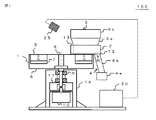
図1は本発明の実施の形態1による渦電流選別装置の構成を示す図である。渦電流選別装置100は、磁界回転円板1、パレット2、供給部3、排出部4、駆動部14、検出器25、制御部30などを備えている。駆動部14は、回転軸8、軸受9、駆動モータ10、カップリング11などから構成されていて、磁界回転円板1に固定されている。被選別対象物は、供給部3の保持容器3bに、一旦、保持および貯蔵されてから、供給レーン3aを通じてパレット2に投入される。この後、被選別混合物は、パレット2で導電性材料と非導電性材料に選別され、排出部4に分別されて保存される。円環状の円板6は凹部を有する。円板6の凹部には円環状の継鉄板7が固定され、その上に永久磁石5(ネオジム磁石)が固定されている。排出部4は、回収容器4a、排出シュート4bおよび開閉弁4cなどから構成されている。
FIG. 1 is a diagram showing a configuration of an eddy current sorting apparatus according to
磁界回転円板1は駆動部14の回転軸8に取り付けられている。回転軸8は軸受9で支持されていて、駆動モータ10にカップリング11、もしくはタイミングベルト等で接続されている。駆動モータ10の回転はカップリング11を介して円板6に伝達される。パレット2は薄い板状の底板12と、底板12を囲む外縁部13によって構成されている。パレット2は、磁界回転円板1の上に、永久磁石5の表面と1〜2mm程度のわずかな間隔を介して配置されている。パレット2と回収容器4aは排出シュート4bで接続されている。パレット2と排出シュート4bの間には開閉弁4cが設置されており、排出部4の回収容器4aの使用状態を開状態および閉状態に設定することができるようになっている。制御部30は検出器25で検出された画像を解析し、被選別対象物の分別度を判定する。制御部30はさらにこの判定結果に基づいてパレット2と供給部3と排出部4と駆動部14に指示を与えて、動作を制御する。 The magnetic
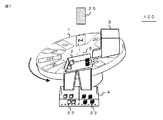
図2に渦電流選別装置100の斜視図を示す。磁界回転円板1は、駆動部14の駆動モータに結合され、上面から見た場合、時計周りに回転している。供給部3は間欠的にパレット2の端部に被選別対象物をできるだけ重ならないように薄く直線状に投入する。排出部4はパレット上の材料を漏れなく回収する機能を有する。具体的には、パレット2を傾斜させる機能、パレット2を振動させ排出する機能、パレット内部の材料を掻きだす機能等が挙げられるが方式は問わない。供給部3に貯蔵されている被選別対象物は、供給レーン3aを通じてパレット2に供給される。投入された被選別対象物は時間が経過すると、パレット2の中で導電性材料22と非導電性材料23に分別される。被選別対象物の分別状況は検出器25を使って監視されている。制御部30が検出器25の検出した画像から被選別対象物の分別度を良であると判定すると、または材料が供給されてから、あらかじめ設定した一定の選別時間が経過すると、排出部4の開閉弁4cが開状態になる。導電性材料22と非導電性材料23は排出シュート4bを通過し、排出部4の回収容器4aに分別された状態で保存される。回収容器4aは導電性材料と非導電性材料を区分するために2個設置されている。 FIG. 2 shows a perspective view of the eddy
図3は磁界回転円板1の構成を示している。永久磁石5は円周方向に磁極が交互になるよう放射状にアルミニウム合金製の円板6の凹部に配置されている。円板6の凹部には円環状の継鉄板7が固定されている。パレット中の磁石近傍に接近する部材は非導電性かつ非磁性の材料で構成されている。特にパレット2の薄板状の底板12はFRP(Fiber Reinforced Plastics)などの剛性が高いものを使用する。磁界回転円板1の中心には、回転軸8が挿入されていて、駆動部14と繋がっている。制御部30は、必要な時に駆動部14に回転の指示を与える。駆動モータ10の回転に連動して磁界回転円板1は回転する。導電性材料22は灰色で、非導電性材料23は白抜きで表すことにする。 FIG. 3 shows the configuration of the magnetic
本発明装置は、上記のような基本構成を有している。この装置による選別動作は図4(図4A〜図4D)に示すように、次のようにして行われる。まず、導電性材料と非導電性材料の混合物である被選別対象物24を供給部3の保持容器3bに投入する(図4A参照)。導電性材料は具体的には直径0.2mm程度以上の破砕銅線やアルミ小片など、外形寸法が数mm〜数10mm程度に破砕および分割された非鉄金属であり、非導電性材料はプラスチック小片、ゴム破砕物、粉体、砂などを指す。供給レーン3aを開くまたは下げると、被選別対象物24は供給部3の保持容器3bからパレット2の片側(投入側2a)に磁界回転円板1の半径方向に直線状に並べられた状態で決められた量、投入される。 The device of the present invention has the basic configuration as described above. As shown in FIG. 4 (FIGS. 4A to 4D), the sorting operation by this apparatus is performed as follows. First, the object to be sorted 24, which is a mixture of a conductive material and a non-conductive material, is put into the holding container 3b of the supply unit 3 (see FIG. 4A). Specifically, the conductive material is a non-ferrous metal whose outer dimensions are crushed and divided into several mm to several tens of mm, such as crushed copper wire and aluminum pieces with a diameter of about 0.2 mm or more, and the non-conductive material is plastic pieces, It refers to crushed rubber, powder, sand, etc. When the supply lane 3a is opened or lowered, the objects to be sorted 24 are arranged linearly in the radial direction of the magnetic
投入が終わると供給レーン3aを閉じるまたは上げる(図4B参照)。投入された被選別対象物24には、パレット2の下部で回転している磁界回転円板1から、高速で磁極が入れ替わる交番磁界が印加される。被選別対象物中の導電性材料は、交番磁界によって、内部に渦電流が発生し、磁界回転円板1との間で電磁力が発生する。これが推進力として働き、導電性材料は永久磁石5の移動方向であるパレット2の反対側(反投入側2b)に移動する。非導電性材料は、内部に渦電流が発生しないため、推進力は発生しない。この状態では、制御部30は被選別対象物の分別度が不十分であると判定する。 When the charging is finished, the supply lane 3a is closed or raised (see FIG. 4B). An alternating magnetic field in which magnetic poles are switched at a high speed is applied from the magnetic
寸法が小さく、小さな推進力しか得られない導電性材料においても、時間をかけるとパレット2の内部を少しずつ移動し、パレット2の反対側(反投入側2b)まで移動する(図4C参照)。一方、非導電性材料は、内部に渦電流が発生しないため、投入された場所から動かない。寸法小で推進力が大きく得られない導電性材料に対しても、非導電性材料と混在しない十分な距離差が生じるだけの時間、推進力を印加する。制御部30が分別度を良と判定するまで分別は進行する。したがって、導電性材料と非導電性材料は時間の経過とともにパレット2の中で高純度に分離する。この状態では、制御部30は被選別対象物の分別度を良と判定する。 Even in a conductive material having a small size and only a small driving force, the inside of the
次に制御部30は、開閉弁4cを開けて、排出部4の回収容器4aを開状態にする(図4D参照)。開状態ではパレット2と回収容器4aは排出シュート4bによって連通している。分離された導電性材料と非導電性材料は排出シュート4bを通って、回収容器4aに分別された状態で保存される。最後に回収容器4aから、分離した導電性材料と非導電性材料をそれぞれ回収することで、選別の1サイクルが完了する。その後、図4Aに戻り、再び新たな被選別混合物が供給部3からパレット2に投入され、次サイクルの選別が開始する。 Next, the
以上より、パレットに材料を投入してから排出するまでの時間を変更することで、導電性材料に推進力を印加する時間を任意に調整することが出来る。導電性材料22と永久磁石5の間はパレット2の底板12の一枚のみであり、その距離は一定であるため、パレット中のどこに材料が移動したとしても、既存装置における最大の推進力と同程度の推進力を与えることができる。したがって、寸法小で推進力が大きく得られない導電性材料に対しても、非導電性材料と混在しない十分な距離差が生じるだけの時間、推進力を印加することができる。 As described above, the time for applying the driving force to the conductive material can be arbitrarily adjusted by changing the time from when the material is charged to the pallet until the material is discharged. Since there is only one
本実施の形態は、被選別対象物を磁界回転円板1の半径方向に送りながら選別するのではなく、バッチ式で、導電性材料のみ移動させる方法である。導電性材料のみ移動しながら選別されるため、選別の過程で非導電性材料が導電性材料側に移動し、混在することが少ないといったメリットが存在する。これらの理由から、直径0.2〜0.6mm程度の細い銅線のような小寸法の導電性材料も非導電性材料と高純度選別が可能となるといった効果を得ることができる。処理量向上のため、磁界回転円板1の大きさを大きくする必要はなく、必要に応じて一つの磁界回転円板1と組み合わせるパレット2の数を増やすことで対応できるといったメリットも存在する。 The present embodiment is a method in which only the conductive material is moved in a batch manner, instead of sorting the objects to be sorted while feeding them in the radial direction of the magnetic
実施の形態2.
実施の形態2に係わる渦電流選別装置を図5と図6に基づいて説明する。渦電流選別装置100は、図5に示すように、回転軸8を傾斜させ、磁界回転円板1およびパレット2が共に同じ向きに傾いて配置されている。磁界回転円板1の上面およびパレット2の水平面(底板12)は推進力が働く方向に傾斜している。パレット2が水平に設置されている場合、導電性材料が推進力によってパレット2の底板上を滑り移動しようとするには、摩擦力に打ち勝って移動する必要がある。
An eddy current sorting apparatus according to the second embodiment will be described with reference to FIGS. As shown in FIG. 5, the eddy
実施の形態2に係る構成によれば、パレットの傾斜によって、被選別対象物に対して推進力が働く方向に重力の分力が作用する。その結果、図6に示すように導電性材料が打ち勝つべき摩擦力が見かけ上小さくなり、より小さな推進力しか発生しない寸法の小さな材料も選別することができる。この構成では非導電性材料の方が導電性材料に比べて摩擦係数が大きい場合、摩擦力の差も併用して選別することができ、より高い選別能力が見込まれる。 According to the configuration according to the second embodiment, due to the inclination of the pallet, the gravitational force acts in the direction in which the driving force acts on the object to be sorted. As a result, as shown in FIG. 6, the frictional force to be overcome by the conductive material is apparently reduced, and it is possible to select a material having a small size that generates only a small driving force. In this configuration, when the friction coefficient of the non-conductive material is larger than that of the conductive material, the non-conductive material can be sorted together with the difference in friction force, and higher sorting ability is expected.
実施の形態3.
実施の形態3に係わる渦電流選別装置を図7に基づいて説明する。渦電流選別装置100は、図に示すように磁界回転円板1の回転軸8およびパレット2の水平面を推進力が働く方向と逆側に傾斜させて配置している。このとき、非導電性材料がパレット2の傾斜によって、滑り落ちる傾斜角に設定する。図では、磁界回転円板1は反時計方向に回転している。この構成によれば、非導電性材料がパレット2を滑りもしくは転動し下部に移動するのに対して、導電性材料が推進力によってパレット2の上方端部に保持されることによって選別を行う。非導電性材料の方が導電性材料に比べ摩擦係数が小さい場合、摩擦係数の差を併用して選別を行うことができる。また、非導電性材料の方が導電性材料に比べて転がり易い形状の場合も有効である。
An eddy current sorting apparatus according to
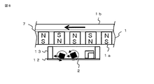
実施の形態4.
実施の形態4に係わる渦電流選別装置を図8に基づいて説明する。渦電流選別装置の磁界回転円板1を永久磁石5の表面が下部に現れるような向きでパレット2の上方に配置している。このため磁界回転円板1の磁石側1aが下を向き、継鉄側1bが上を向いている。通常、1つの磁界回転円板1で推進力を与える場合、推進力には並進方向の力と回転方向の力が生じる。この構成によれば、回転力によって導電性材料がパレット上を転がろうとする向きが、並進方向の力の向きと同じになるので、並進方向の力に加えて回転力も利用して選別を行うことができる。したがって、特に転がり易い導電性材料の選別に有効である。
An eddy current sorting apparatus according to
実施の形態5.
実施の形態5に係わる渦電流選別装置を図9に基づいて説明する。ここでは底板の厚さが投入側から反投入側に向かって途中から増加している。例えば、渦電流選別装置100は、図に示すように、パレット2の底板12の厚さを反投入側の外縁部13の近くで厚くしている。寸法や形状が異なる導電性材料を同時に選別しようとする際、導電性材料に生じる推進力にばらつきが生じる。推力小の導電性材料に合わせて装置の設定を行う場合、同時に選別する推力大の導電性材料の速度が必要以上に大きくなり、パレットの外縁部13に強く衝突し、跳ね返ることで、その他の被選別材料に影響を与えことが考えられる。この構成によれば、導電性材料がパレット2の中で速度を上げた場合、底板12の厚くなった領域で永久磁石5と導電性材料との距離が離れて推進力が小さくなり、外縁部に強く衝突しない。このことから、寸法にばらつきがある等の理由で推進力の異なる導電性材料が混在する被選別材料を選別する際に有効である。
An eddy current sorting apparatus according to the fifth embodiment will be described with reference to FIG. Here, the thickness of the bottom plate increases from the input side toward the non-input side. For example, in the eddy
実施の形態6.
実施の形態6に係わる渦電流選別装置を図10に基づいて説明する。ここでは底板の厚さが投入側から反投入側に向かって一定の割合で増加している。例えば、渦電流選別装置100は、図に示すように磁界回転円板1の表面と底板12の上面の角度を平行な面から傾斜させている。また、回収容器4aが3個設けられている。この構成によれば、永久磁石5の表面と導電性材料との距離が大きくなるほど推進力が小さくなることから、導電性材料がパレット中を移動するほど推進力が徐々に小さくなる。したがって、寸法大もしくは電気伝導度が大きい材料はパレット中を進む距離が大きくなるのに対して、寸法が小さいもしくは電気伝導度の小さい材料が移動できる距離は小さくなる。これを複数の排出口を有する排出部4で回収することで、材料の電気伝導度や寸法の大小によって被選別対象物を複数段階に選別することができる。
An eddy current sorting apparatus according to
実施の形態7.
実施の形態7に係わる渦電流選別装置を図11に基づいて説明する。渦電流選別装置100は、図に示すようにパレット2に対して振動を印加している。具体的には、パレットに被選別材料が存在する間、超音波振動子20を用いて面外方向に微小振動を印加する。もしくは偏心錘付きモータによって間欠的に比較的大きな振動を印加する。この構成によれば、前者は被選別対象物がパレット2に触れる時間が短くなり、摩擦力が小さくなる。それにより、より小さな推進力しか生まれない小寸法の導電性材料も選別することができる。後者においては、導電性材料の前方に非導電性材料が存在し、移動が阻害されているような状況があった場合において、両者の位置関係をずらし、選別を続行することができる。
An eddy current sorting apparatus according to the seventh embodiment will be described with reference to FIG. The eddy
実施の形態8.
実施の形態8に係わる渦電流選別装置を図12に基づいて説明する。渦電流選別装置100は、図に示すようにパレットに対して選別時にパレット内外を遮断する蓋21をとりつけている。この蓋21は被選別対象物が供給部から投入される際と、排出部に分離が完了した材料を受け渡す際のみ開く構造など、被選別対象物の供給時排出時にはその動作を阻害しないものとする。この構成によれば、被選別対象物が選別中にパレット外へ飛び出すことがない。また、パレット下部の磁界回転円板の回転によって生じた気流による影響など、パレット外部から被選別材料に与えられる外乱を減ずることができる。
An eddy current sorting apparatus according to the eighth embodiment will be described with reference to FIG. As shown in the figure, the eddy
実施の形態9.
実施の形態9に係わる渦電流選別装置を図13に基づいて説明する。磁界回転円板1をパレット2の下部に、補助磁界回転円板17をパレット2の上部に配置している。補助磁界回転円板17は、磁石側1aを下に向けてパレットの上方に配置されている。このとき上部と下部の磁界回転円板は同じ回転軸8に接続するなどして、常に上下で対向している永久磁石5の磁極が逆になるよう同期して回転させる。すなわち補助磁界回転円板17は、磁界回転円板1と回転軸8を共有し、対向する永久磁石の極性が逆になっている。この構成によれば、単一の磁界回転円板を用いるときに比べ、パレット内の磁束密度が高くなり、並進方向の推進力がより大きくなるといった利点がある。
An eddy current sorting apparatus according to
実施の形態10.
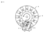
実施の形態10に係わる渦電流選別装置を図14と図15に基づいて説明する。渦電流選別装置100は、図14のように、1組の磁界回転円板1、供給部3、および排出部4に対して、複数のパレット2を配置している。この例では、6個のパレット2をパレット駆動リング18にパレット傾斜軸19を介して接続し、円環状に並べて配置している。被選別対象物は供給部3から供給レーン3aを通じて投入位置にあるパレット2に供給される。図では5時の方向に到達したパレットが投入位置にある。投入位置にあるパレットは、供給レーン3aと重なる。パレット駆動モータ15を用いてパレット駆動リング18を回転させることで、パレット2を磁界回転円板1の上部で低速周回させている。パレット駆動方法は、これ以外にも、パレットにカムフォロアを取り付け、レール上を移動させる方法など、複数のパレットを移動させる方法であればいずれでもよい。
An eddy current sorting apparatus according to
制御部30は複数のパレットにおける被選別対象物の分別度を判定している。どれかのパレットに於いて被選別対象物の分別度を良と判定した場合、または一定の選別時間が経過している場合、そのパレットが排出位置に到達すると排出部に開状態を指示する。排出位置ではパレット2と排出部4が重なる。図では、3時の方向にある右端のパレットが排出位置に到達している。この構成における排出部4の例を図15に示す。パレット2は選別時には、水平に保たれているが、排出時はパレット傾斜軸19を中心にパレットが傾斜している。パレットが傾斜しているときに、回収容器4aは使用状態が開状態にあり、水平時には閉状態にある。分離された導電性材料と非導電性材料は排出シュート4bを通して排出部4に排出される。 The
この場合、パレット2を間欠的に回転させるか、一定速度で回転させ、排出シュート4bをパレット2の動きに合わせて揺動させる方法のいずれでもよい。本構成によれば、パレット2の数を増加させることで、磁界回転円板中の磁石から生じる磁束密度を無駄なく利用することができる。また、パレット2の数に対して供給部3、排出部4の数を減らし、供給部3および排出部4の稼働率を高めることができる。したがって、磁界回転円板1、供給部3および排出部4の数をパレット2の数だけ増やすことなく、処理量の増加が可能となる。その結果、装置の占有面積および、装置コストの増加を小さく抑えることができる。 In this case, any method of intermittently rotating the
パレット2の周回速度を調整することで、被選別混合物が渦電流の作用を受けやすさ如何によって、簡単に選別時間を調整することができる。具体的には、寸法が大で、推進力が比較的大きな導電性材料の選別時には周回速度を上昇させ、短時間で選別を行い、処理量を増やすことができる。反対に、寸法が小さく、推進力が小さな導電性材料の選別時には周回速度を低下させることで、より長時間の選別時間を与え、高純度の選別を行うことができる。 By adjusting the rotating speed of the
実施の形態11.
実施の形態11に係わる渦電流選別装置を図16に基づいて説明する。渦電流選別装置100は、一つの回転軸8に複数の磁界回転円板1を結合しているため、磁界回転円板1は回転軸8を共有している。図には一つの回転軸8に3つの磁界回転円板1を固定した例を示している。この構成では、駆動モータ10の数を1つに抑えたまま、供給部3で流路を3分割し、それぞれの磁界回転円板1とパレット2の組み合わせで同様の選別を行うことで、並列処理を行い、処理量を3倍に増やすことができる。Embodiment 11 FIG.
An eddy current sorting apparatus according to Embodiment 11 will be described with reference to FIG. In the eddy
また、縦のスペースを有効活用することで、装置の占有面積を大きく増やすことなく処理量を増加させることができる。さらに、それぞれの磁界回転円板において、上から順にワークに加わる磁束密度を大きくなるよう設定し、それぞれの排出部を次の供給部に直列に接続することで、各磁界回転円板で段階的に選別を行ってもよい。たとえば、寸法の大きい導電性材料を一番上の磁界回転円板で選別し、残った寸法の小さい導電性材料と非導性材料を2番目と3番目の磁界回転円板で並列に選別するといった流れの選別が可能となる。 Further, by effectively utilizing the vertical space, the processing amount can be increased without greatly increasing the area occupied by the apparatus. Furthermore, in each magnetic field rotating disk, the magnetic flux density applied to the workpiece is set so as to increase in order from the top, and each discharging part is connected in series to the next supply part, so that each magnetic field rotating disk is stepwise. Sorting may be performed. For example, a conductive material having a large dimension is sorted by the top magnetic rotating disk, and the remaining small conductive material and non-conductive material are sorted in parallel by the second and third magnetic rotating disks. It is possible to sort such flows.
実施の形態12.
実施の形態12に係わる渦電流選別装置を図17に基づいて説明する。渦電流選別装置100は、磁界回転円板1、パレット2、供給部3、排出部4、駆動部14、揺動機構26、制御部30などを備えている。駆動部14は、回転軸8、軸受9、駆動モータ10、カップリング11などから構成されていて、磁界回転円板1に固定されている。被選別対象物は、供給部3の保持容器3bに、一旦、保持および貯蔵されてから、供給レーン3aを通じてパレット2に投入される。この後、被選別混合物は、パレット2で導電性材料と非導電性材料に選別され、排出部4に分別されて保存される。円環状の円板6は凹部を有する。円板6の凹部には円環状の継鉄板7が固定され、その上に永久磁石5(ネオジム磁石)が固定されている。排出部4は、回収容器4a、排出シュート4bおよび排出機構4dなどから構成されている。
An eddy current sorting apparatus according to
磁界回転円板1は駆動部14の回転軸8に取り付けられている。回転軸8は軸受9で支持されていて、駆動モータ10にカップリング11、もしくはタイミングベルト等で接続されている。駆動モータ10の回転はカップリング11を介して円板6に伝達される。磁界回転円板1の回転速度は制御部30が制御する。パレット2は薄い板状の底板12と、底板12を囲む外縁部13によって構成されている。パレット2は、磁界回転円板1の上に、永久磁石5の表面と1〜2mm程度のわずかな間隔を介して配置されている。パレット2は、選別時には磁界回転円板1と水平に保たれているが、排出機構4dが動作して排出部4が開状態になると傾斜している(図15参照)。パレット中の、磁石近傍に接近する部材は、非導電性かつ非磁性の材料で構成されている。特に底板12は、アルミナやFRP(Fiber Reinforced Plastics)など、非電導性、非磁性および高剛性の特性を有するものを使用する。 The magnetic
磁界回転円板1は、駆動部14の駆動モータに結合され、上面から見た場合、時計周りに回転している。供給部3は間欠的にパレット2の端部に被選別対象物をできるだけ重ならないように薄く直線状に投入する。排出部4はパレット上で分離した材料をそれぞれ混ざらないよう漏れなく回収する機能を有する。供給部3に貯蔵されている被選別対象物は、供給レーン3aを通じてパレット2に供給される。投入された被選別対象物は時間が経過するに従って、パレット2の中で導電性材料22と非導電性材料23に分離される。パレット2に投入されてから十分分離するまでの時間は投入する被選別対象物の特性によって異なる。 The magnetic
渦電流の作用によって被選別対象物に発生する推進力の大きさは、対象物の電気伝導度、質量、形状、寸法などに依存する。投入から排出までの選別時間を被選別対象物に対応してあらかじめ設定することによって、高純度な分離が可能になる。選別時間が経過した後、分離した導電性材料22と非導電性材料23は、それぞれパレット2から取り出される。被選別対象物は、排出機構4dによって、排出シュート4bを通過し、回収容器4aに分別された状態で保存される。回収容器4aは導電性材料と非導電性材料を区分するために2個設置されている。 The magnitude of the propulsive force generated on the object to be sorted by the action of the eddy current depends on the electrical conductivity, mass, shape, dimension, etc. of the object. By setting the sorting time from input to discharge in advance corresponding to the object to be sorted, high-purity separation becomes possible. After the sorting time has elapsed, the separated
この装置による選別動作は、次のようにして行われる。まず、制御部30は磁界回転円板1を常時回転させながら、導電性材料と非導電性材料の混合物である被選別対象物24を供給部3の保持容器3bに投入する(図4A参照)。導電性材料は具体的には直径0.2mm程度以上の破砕銅線やアルミ小片など、外形寸法が数mm〜数10mm程度に破砕および分割された非鉄金属であり、非導電性材料はプラスチック小片、ゴム破砕物、粉体、砂などを指す。供給レーン3aを開くまたは下げると、被選別対象物24は供給部3の保持容器3bからパレット2の片側(投入側2a)に磁界回転円板1の半径方向に直線状に並べられた状態で規定量、投入される。 The sorting operation by this apparatus is performed as follows. First, the
投入が終わると供給レーン3aを閉じるまたは上げる(図4B参照)。投入された被選別対象物24には、パレット2の下部で常時回転している磁界回転円板1から、高速で磁極が入れ替わる交番磁界が印加される。被選別対象物中の導電性材料は、交番磁界によって、内部に渦電流が発生し、磁界回転円板1との間で電磁力が発生する。これが推進力として働き、導電性材料は永久磁石5の移動方向であるパレット2の反対側(反投入側2b)に移動する。非導電性材料は、内部に渦電流が発生しないため、推進力は発生しない。
When the charging is finished, the supply lane 3a is closed or raised (see FIG. 4B). An alternating magnetic field in which magnetic poles are switched at a high speed is applied from the magnetic
導電性材料の前方に非導電性材料が存在し、移動が阻害されているような状況では、導電性材料を移動させることは困難である。本実施の形態では、揺動機構26が、図18のように、選別時にパレット2を回転磁石の近傍で磁石表面とパレット表面を平行に保ちながら揺動運動させる。この構成によれば、導体の受ける推進力の方向はパレットの向きに対して一定ではないので、導電性材料の移動の軌道は、パレットの揺動運動に従って変化する。図19のように軌道がジグザグに変化することで、導電性材料を前方の非導電性材料に阻害されることなく移動させ、選別を続行することができる。揺動運動はリンク機構、カム機構などいずれを用いてもよい。制御部30は、揺動運動の角度と周期を被選別対象物によって変更する。
In a situation where a non-conductive material is present in front of the conductive material and the movement is hindered, it is difficult to move the conductive material. In the present embodiment, as shown in FIG. 18, the
寸法が小さく、小さな推進力しか得られない導電性材料においても、時間をかけるとパレット2の内部を少しずつ移動し、パレット2の反対側(反投入側2b)まで移動する(図4C参照)。一方、非導電性材料は、内部に渦電流が発生しないため、投入された場所から動かない。寸法小で推進力が大きく得られない導電性材料に対しても、非導電性材料と混在しない十分な距離差が生じるだけの時間、推進力を印加する。 Even in a conductive material having a small size and only a small driving force, the inside of the
十分な距離差が生じるだけの時間は被選別対象物によって異なるため、あらかじめ実験的にパレット2に材料を投入し、十分な距離差が生じる時間を把握し、選別時間として制御部30に設定しておく。制御部30は、パレット内に材料が投入されてから、設定した一定の選別時間が経過すると、排出部4を閉状態から開状態に変更する。本実施の形態では、排出機構4dが動作してパレット2が傾斜することで、被選別対象物をパレット2から回収容器4aに排出する(図17参照)。パレット2が傾斜すると分離された導電性材料と非導電性材料は排出シュート4bを通って、回収容器4aに分別された状態で保存される(図4D参照)。その後、排出部4を閉状態に戻すために排出機構4dを停止状態(または通常状態)に変更し、パレット2を平行にする。 Since the time for which a sufficient distance difference is generated varies depending on the object to be sorted, the material is experimentally introduced into the
排出機構4dとしては、パレットの内部材料を回転ブラシ31で掻きだす機構(図20参照)、リンク機構やカム機構でブラシ32を駆動し、このブラシでパレットの内部材料を掻きだす機構(図21参照)、エアノズル33から圧縮空気を送り材料を飛ばして分別する機構(図22参照)等も挙げられるが方式は問わない。凸部2aは、排出機構4dが閉状態(または停止状態)のとき、被選別対象物が回収容器4aに排出されることを防止するために設けてある。以上より、選別の1サイクルが完了するので、再び新たな被選別対象物を供給部3からパレット2に投入すると、次サイクルの選別が開始する(図4A参照)。このサイクルを繰り返すことによって、供給部に貯蔵されている被選別対象物が回収容器4aに導電性材料と非導電性材料に順次分けて保存される。 As the discharge mechanism 4d, a mechanism for scraping the internal material of the pallet with the rotating brush 31 (see FIG. 20), a mechanism for driving the
以上より、パレットに材料を投入してから排出するまでの時間を変更することで、導電性材料に推進力を印加する時間を任意に調整することが出来る。導電性材料22と永久磁石5の間はパレット2の底板12の一枚のみであり、その距離は一定であるため、パレット中のどこに材料が移動したとしても、既存装置における最大の推進力と同程度の推進力を与えることができる。したがって、寸法小で推進力が大きく得られない導電性材料に対しても、非導電性材料と混在しない十分な距離差が生じるだけの時間、推進力を印加することができる。 As described above, the time for applying the driving force to the conductive material can be arbitrarily adjusted by changing the time from when the material is charged to the pallet until the material is discharged. Since there is only one
実施の形態13.
実施の形態13に関わる渦電流選別装置を図に基づいて説明する。図23は本発明の実施の形態による渦電流選別装置の構成を示す図である。渦電流選別装置100は、回収容器4aが3個設けられている。被選別対象物はパレット2の中央部に投入されるようになっている。導電性材料の中には転がり易い形状を有する導電性材料22aと転がりにくい形状を有する導電性材料22bが混在している。被選別対象物に、1つの磁界回転円板1で推進力を与える場合、推進力には並進方向の力と回転方向の力が生じる。したがって、転がり易い形状のものは、回転方向の力が並進方向の力を上回り、図中右側に移動し、転がりにくい形状のものは並進方向の力によって図中左側に滑り移動する。この構成によれば、転がり易い形状のものと転がりにくい形状のものが被選別混合物中に混在している場合でも、その移動方向にて回収することにより、選別を行うことができる。
An eddy current sorting apparatus according to
実施の形態14.
実施の形態14に関わる渦電流選別装置を図に基づいて説明する。図24は本発明の実施の形態による渦電流選別装置の構成を示す図である。渦電流選別装置100は、パレット内部の被選別対象物の分離状況を把握する誘導型の近接センサー27を備えている。近接センサー27は、選別が進行し、導電性材料22が近づいてくると、感応する。選別状況は制御部30に伝達される。近接センサー27は、渦電流で導体が加熱されたことを検知する温度センサーで代用することができる。制御部30は、排出部にパレット上の材料を回収するタイミングを指示し、指示を受けた排出部はパレット上の材料を回収する。回収が完了すると制御部は供給部に対して新たな材料をパレット上に投入するよう指示を送る。この方法によれば、パレットに材料を投入してから材料を排出するまでの選別時間を、各サイクル毎に判断し、変更する。被選別対象物の寸法ばらつきや材質などの変動が大きい場合においても、選別時間の無駄を出来る限り少なくすることで処理量を落とさず、選別純度を保つことができる。
An eddy current sorting apparatus according to
以上のような構成および動作を行う本発明による渦電流選別装置は、次のような効果を有している。渦電流選別の特性上、被選別対象物中の導電性材料の寸法が小さくなればなるほど、発生する推進力は小さくなることから、導電性材料を非導電性材料から十分離し、純度よく分離させるために必要な時間は長くなる。この発明によれば、パレット内部に材料を投入してから排出するまでの時間を変更することにより、選別対象の導電性材料に応じて、推進力を印加する時間を容易に長く設定することができる。 The eddy current sorting apparatus according to the present invention having the above-described configuration and operation has the following effects. Due to the characteristics of eddy current sorting, the smaller the size of the conductive material in the object to be sorted, the smaller the propulsive force that is generated. Therefore, the conductive material is sufficiently separated from the non-conductive material and separated with high purity. The time required for this becomes longer. According to this invention, by changing the time from when a material is put into the pallet to when it is discharged, the time for applying the propulsive force can be easily set longer according to the conductive material to be selected. it can.
導電性材料と磁石表面の間はパレット一枚のみであり、その距離は小さくかつ一定であるため、パレット中のどこに材料が移動したとしても、既存装置における最大の推進力と同程度以上の推進力を与えることができる。また、パレット上で導電性材料のみ移動しながら選別されるため、導電性材料と非導電性材料が共に移動して選別を行う従来の回転円盤磁石方式に比べ、選別の過程で非導電性材料が導電性材料側に移動し、混在することが少ない。 Since there is only one pallet between the conductive material and the magnet surface, and the distance is small and constant, no matter where the material moves in the pallet, the propulsion equal to or greater than the maximum propulsive force in the existing equipment Can give power. In addition, since only the conductive material is moved on the pallet, it is sorted, so the non-conductive material is selected during the sorting process compared to the conventional rotating disk magnet method in which the conductive material and the non-conductive material move together for sorting. Moves to the conductive material side and is rarely mixed.
上記の効果により、0.2〜0.6mmφ程度の細い銅線のような小寸法の導電性材料に対しても高純度選別が可能となる。また、回転円盤磁石の半径方向に送りながら選別する既存の技術と異なり、パレット上の投入された場所で選別が行われるため、選別に回転磁石の半径方向の長さを必要としない。したがって、処理量向上のため、回転磁石の半径を大きくする必要がなく、必要に応じて一つの回転磁石と組み合わせるパレットの数を増やすことで対応することができる。 Due to the above effects, high-purity sorting can be performed even for a small-sized conductive material such as a thin copper wire of about 0.2 to 0.6 mmφ. In addition, unlike the existing technique of sorting while feeding in the radial direction of the rotating disk magnet, sorting is performed at the place where it is put on the pallet, so that the length of the rotating magnet in the radial direction is not required for sorting. Therefore, it is not necessary to increase the radius of the rotating magnet in order to improve the processing amount, and this can be dealt with by increasing the number of pallets combined with one rotating magnet as necessary.
なお、本発明は、その発明の範囲内において、実施の形態を自由に組み合わせたり、各実施の形態を適宜、変形、省略することが可能である。 It should be noted that the present invention can be freely combined with each other within the scope of the invention, and each embodiment can be appropriately modified or omitted.
1 磁界回転円板、1a 磁石側、1b 継鉄側、2 パレット、2a 投入側、2b反投入側、3 供給部、3a 供給レーン、3b 保持容器、4 排出部、4a 回収容器、4b 排出シュート、4c 開閉弁、5 永久磁石、6 円板、7 継鉄板、8 回転軸、9 軸受、10 駆動モータ、11 カップリング、12 底板、13 外縁部、14 駆動部、15 パレット駆動モータ、17 補助磁界回転円板、18 パレット駆動リング、19 パレット傾斜軸、20 超音波振動子、21 蓋、22 導電性材料、23 非導電性材料、24 被選別対象物、25 検出器、30 制御部、100 渦電流選別装置。 1 magnetic rotating disk, 1a magnet side, 1b yoke side, 2 pallet, 2a input side, 2b non-input side, 3 supply part, 3a supply lane, 3b holding container, 4 discharge part, 4a recovery container, 4b discharge chute 4c On-off valve, 5 Permanent magnet, 6 disc, 7 yoke plate, 8 Rotating shaft, 9 Bearing, 10 Drive motor, 11 Coupling, 12 Bottom plate, 13 Outer edge, 14 Drive, 15 Pallet drive motor, 17 Auxiliary Magnetic rotating disk, 18 pallet drive ring, 19 pallet tilt axis, 20 ultrasonic transducer, 21 lid, 22 conductive material, 23 nonconductive material, 24 object to be sorted, 25 detector, 30 control unit, 100 Eddy current sorting device.
Claims (20)
前記磁界回転円板から間隔を隔てて配置されるパレットと、
回転軸が前記磁界回転円板に取り付けられている駆動部と、
被選別対象物を保持し、前記パレットに規定量の被選別対象物を供給する供給部と、
2個の回収容器を有し、閉状態から開状態になると前記供給部から前記パレットに供給された被選別対象物をこの回収容器に回収する排出部と、
前記磁界回転円板、前記駆動部、前記供給部および前記排出部を制御する制御部と、を備え、
前記供給部から前記パレットに規定量の被選別対象物を供給する第1工程と、
前記第1工程の終了後、一定時間が経過すると、前記排出部を閉状態から開状態にする第2工程と、
前記第2工程の終了後、前記排出部を閉状態に戻す第3工程を、実行し、
前記第3工程が終了すると、前記第1工程から前記第3工程までを再度実行することを特徴とする渦電流選別装置。 A magnetic rotating disk in which a plurality of permanent magnets are arranged in the circumferential direction by alternately inverting the polarity;
A pallet disposed at a distance from the magnetic rotating disk;
A driving unit having a rotating shaft attached to the magnetic field rotating disk;
A supply unit for holding the object to be sorted and supplying a predetermined amount of the object to be sorted to the pallet;
A discharge unit that has two collection containers and collects the objects to be sorted supplied from the supply unit to the pallet when the closed state is opened,
A controller that controls the magnetic field rotating disk, the drive unit, the supply unit, and the discharge unit,
A first step of supplying a specified amount of objects to be sorted from the supply unit to the pallet;
After the end of the first step, when a certain time has elapsed, a second step of bringing the discharge part from a closed state to an open state;
After the end of the second step, a third step of returning the discharge part to the closed state is performed,
When the third step is finished, the eddy current sorting device is characterized in that the first step to the third step are executed again.
前記パレットは、前記磁界回転円板の上方に配置されていることを特徴とする請求項1に記載の渦電流選別装置。 The magnetic field rotating disk is arranged with the magnet side facing up,
The eddy current sorting apparatus according to claim 1, wherein the pallet is disposed above the magnetic field rotating disk.
前記補助磁界回転円板は、磁石側を下に向けて前記パレットの上方に配置されていることを特徴とする請求項2に記載の渦電流選別装置。 Auxiliary magnetic field rotating disk having a plurality of permanent magnets arranged in the circumferential direction by reversing the polarity alternately,
The eddy current sorting device according to claim 2, wherein the auxiliary magnetic field rotating disk is disposed above the pallet with a magnet side facing downward.
前記供給部は、前記被選別対象物を前記パレットの中央部に供給することを特徴とする請求項1に記載の渦電流選別装置。 The discharge part has three collection containers,
The eddy current sorting apparatus according to claim 1, wherein the feeding unit feeds the object to be sorted to a central part of the pallet.
前記磁界回転円板から間隔を隔てて配置されるパレットと、
前記パレットに供給された導電性材料と非導電性材料を含む被選別対象物の画像を検出する検出器と、
前記検出器が検出する画像に基づいて前記被選別対象物の分別度を判定する制御部と、
回転軸が前記磁界回転円板に取り付けられていて、前記制御部の指示に従って前記磁界回転円板を回転する駆動部と、
前記被選別対象物を保持し、前記制御部の指示に従って前記パレットの投入側に規定量の被選別対象物を供給する供給部と、
2個の回収容器を有し、前記制御部の指示に従って前記回収容器の使用状態を開状態または閉状態に設定する排出部と、を備え、
前記制御部は、
前記供給部に前記被選別対象物の供給を指示する第1工程と、
前記排出部に閉状態を指示し、前記駆動部には前記磁界回転円板の回転を指示する第2工程と、
前記検出器から被選別対象物の画像を取得し、この画像から被選別対象物の分別度を判定する第3工程と、
前記被選別対象物の分別度を良と判定した場合、前記排出部に開状態を指示する第4工程とを、実行し、
前記第4工程が完了すると、前記第1工程から前記第4工程までを再度実行することを特徴とする渦電流選別装置。 A magnetic rotating disk in which a plurality of permanent magnets are arranged in the circumferential direction by alternately inverting the polarity;
A pallet disposed at a distance from the magnetic rotating disk;
A detector for detecting an image of an object to be sorted including a conductive material and a non-conductive material supplied to the pallet;
A control unit for determining a classification degree of the object to be sorted based on an image detected by the detector;
A rotation unit attached to the magnetic field rotation disk, and a drive unit that rotates the magnetic field rotation disk according to an instruction of the control unit;
A supply unit that holds the object to be sorted and supplies a predetermined amount of the object to be sorted to the input side of the pallet according to an instruction of the control unit;
A discharge unit having two collection containers, and setting the use state of the collection container to an open state or a closed state in accordance with an instruction from the control unit;
The controller is
A first step of instructing the supply unit to supply the object to be sorted;
A second step of instructing the discharge unit to be closed, and instructing the drive unit to rotate the magnetic field rotating disk;
A third step of acquiring an image of the object to be selected from the detector and determining a degree of separation of the object to be selected from the image;
When it is determined that the classification of the object to be sorted is good, the fourth step of instructing the discharge unit to open is performed,
When the fourth step is completed, the eddy current sorting apparatus is configured to execute again the first step to the fourth step.
前記磁界回転円板から間隔を隔てて配置されるパレットと、
回転軸が前記磁界回転円板に取り付けられている駆動部と、
被選別対象物を保持し、前記パレットに規定量の被選別対象物を供給する供給部と、
2個の回収容器を有し、閉状態から開状態になると前記供給部から前記パレットに供給された被選別対象物をこの回収容器に回収する排出部と、
前記磁界回転円板、前記駆動部、前記供給部および前記排出部を制御する制御部と、を備えた渦電流選別装置における渦電流選別方法であって、
前記供給部から前記パレットに規定量の被選別対象物を供給する第1工程と、
前記第1工程の終了後、一定時間が経過すると、前記排出部を閉状態から開状態にする第2工程と、
前記第2工程の終了後、前記排出部を閉状態に戻す第3工程とを、備え、
前記第3工程が終了すると、前記第1工程から前記第3工程までを再度実行することを特徴とする渦電流選別方法。 A magnetic rotating disk in which a plurality of permanent magnets are arranged in the circumferential direction by alternately inverting the polarity;
A pallet disposed at a distance from the magnetic rotating disk;
A driving unit having a rotating shaft attached to the magnetic field rotating disk;
A supply unit for holding the object to be sorted and supplying a predetermined amount of the object to be sorted to the pallet;
A discharge unit that has two collection containers and collects the objects to be sorted supplied from the supply unit to the pallet when the closed state is opened,
An eddy current sorting method in an eddy current sorting device comprising the magnetic field rotating disk, the drive unit, the supply unit, and a control unit that controls the discharge unit,
A first step of supplying a specified amount of objects to be sorted from the supply unit to the pallet;
After the end of the first step, when a certain time has elapsed, a second step of bringing the discharge part from a closed state to an open state;
A third step of returning the discharge part to a closed state after the end of the second step,
When the third step is completed, the eddy current selection method is characterized in that the first step to the third step are executed again.
Applications Claiming Priority (3)
| Application Number | Priority Date | Filing Date | Title |
|---|---|---|---|
| JP2014137349 | 2014-07-03 | ||
| JP2014137349 | 2014-07-03 | ||
| PCT/JP2015/056456 WO2016002256A1 (en) | 2014-07-03 | 2015-03-05 | Eddy current selection device and eddy current selection method |
Publications (2)
| Publication Number | Publication Date |
|---|---|
| JPWO2016002256A1 JPWO2016002256A1 (en) | 2017-04-27 |
| JP6289638B2 true JP6289638B2 (en) | 2018-03-07 |
Family
ID=55018819
Family Applications (1)
| Application Number | Title | Priority Date | Filing Date |
|---|---|---|---|
| JP2016531134A Expired - Fee Related JP6289638B2 (en) | 2014-07-03 | 2015-03-05 | Eddy current sorting apparatus and eddy current sorting method |
Country Status (4)
| Country | Link |
|---|---|
| EP (1) | EP3165293B1 (en) |
| JP (1) | JP6289638B2 (en) |
| CN (1) | CN106457314A (en) |
| WO (1) | WO2016002256A1 (en) |
Families Citing this family (7)
| Publication number | Priority date | Publication date | Assignee | Title |
|---|---|---|---|---|
| WO2018112509A1 (en) * | 2016-12-20 | 2018-06-28 | Cyclomag Pty Limited | Planar magnetic separator |
| CN108537973A (en) * | 2018-03-29 | 2018-09-14 | 上海工程技术大学 | A kind of vending machine and its sell management system, method |
| CN108686984B (en) * | 2018-05-16 | 2023-11-03 | 绵阳西磁磁业有限公司 | Device and method for automatically sorting magnetism of permanent magnet |
| DE102018133387B4 (en) * | 2018-12-21 | 2024-04-11 | Leibniz-Institut für Photonische Technologien e. V. | SPECIFIC NANOPARTICLE SORTER AND METHOD FOR SORTING NANOPARTICLES |
| CN112452776A (en) * | 2020-11-16 | 2021-03-09 | 史洪扬 | Commodity circulation sorting machine permanent magnetism crawler-type bottom surface drive mechanism and commodity circulation sorting machine |
| CN114798167A (en) * | 2022-04-27 | 2022-07-29 | 格林美(武汉)城市矿山产业集团有限公司 | Double-layer belt type eddy current separator |
| CN114798163A (en) * | 2022-04-27 | 2022-07-29 | 格林美(武汉)城市矿山产业集团有限公司 | Disc type vortex force sorting machine |
Family Cites Families (10)
| Publication number | Priority date | Publication date | Assignee | Title |
|---|---|---|---|---|
| ZA886696B (en) * | 1987-09-11 | 1989-04-26 | Alcan Int Ltd | Method of separating metal alloy particles |
| US5522513A (en) * | 1994-03-30 | 1996-06-04 | Howell; Billy R. | Separator disc |
| CA2254934A1 (en) * | 1996-05-17 | 1997-11-27 | Hubertus Exner | Device and process for separating particles with a rotary magnet system |
| DE19629110C1 (en) * | 1996-07-19 | 1997-03-06 | Wester Tonbergbau Kg | Magnetic field separation system for fine particle mixture |
| US6451207B1 (en) * | 1997-06-04 | 2002-09-17 | Dexter Magnetic Technologies, Inc. | Magnetic cell separation device |
| DE19737161A1 (en) * | 1997-08-26 | 1999-04-22 | Hamos Gmbh Recycling Und Separ | Separation of shredded ferrous and nonferrous metals |
| JP2003103195A (en) * | 2001-09-28 | 2003-04-08 | Kenzo Takahashi | Shifting magnetic field type drum magnetic separator |
| FR2884735B1 (en) * | 2005-04-21 | 2007-10-12 | Magpro Sarl | MAGNETIC SEPARATOR OF NON-FERROUS METAL CONDUCTING ELEMENTS AND SELECTIVE SORTING PLANT COMPRISING SUCH SEPARATORS |
| DE102010036267A1 (en) * | 2010-09-03 | 2012-03-08 | Alexander Koslow | Separation method and apparatus for non-ferrous metals |
| CN202387552U (en) * | 2011-12-30 | 2012-08-22 | 北京斯洛玛格技术有限公司 | Eddy current magnetic separation machine |
-
2015
- 2015-03-05 JP JP2016531134A patent/JP6289638B2/en not_active Expired - Fee Related
- 2015-03-05 EP EP15814598.7A patent/EP3165293B1/en active Active
- 2015-03-05 WO PCT/JP2015/056456 patent/WO2016002256A1/en active Application Filing
- 2015-03-05 CN CN201580031803.6A patent/CN106457314A/en active Pending
Also Published As
| Publication number | Publication date |
|---|---|
| CN106457314A (en) | 2017-02-22 |
| EP3165293B1 (en) | 2020-01-08 |
| JPWO2016002256A1 (en) | 2017-04-27 |
| WO2016002256A1 (en) | 2016-01-07 |
| EP3165293A4 (en) | 2018-02-28 |
| EP3165293A1 (en) | 2017-05-10 |
Similar Documents
| Publication | Publication Date | Title |
|---|---|---|
| JP6289638B2 (en) | Eddy current sorting apparatus and eddy current sorting method | |
| CN105323445B (en) | Magnetic suspension video camera | |
| JP2019048271A (en) | Eddy current selection device and eddy current selection method | |
| CN106824981B (en) | A kind of automation detachment of worn-out electrical appliances system | |
| KR101462169B1 (en) | Apparatus for raw material | |
| CN102350400B (en) | Dry magnetic separator | |
| JP2004513768A (en) | Apparatus for separating non-magnetic metal and Fe component from solid mixture and method of operating this apparatus | |
| KR20140116571A (en) | A Magnetic Separator | |
| KR102298216B1 (en) | Nonferrous metal screening system using eddy current. | |
| KR101741315B1 (en) | Slant Type Eddy Current Selector | |
| CN213000566U (en) | Dry type fine separator | |
| WO2016198086A1 (en) | A component feeder and a system for sorting components | |
| JP2008501521A (en) | Magnetic separator for ferromagnetic material provided with slip-controlled rotating roller and suitable operation method | |
| CN101543804B (en) | Electromagnetic damping effect classifier of non-magnetic material | |
| RU2380164C1 (en) | Drum magnetic separator | |
| CN105562344A (en) | Pneumatic separating device | |
| JP2012110812A (en) | Empty can sorting device | |
| CN202080681U (en) | Industrial automatic conveying device | |
| CN216704684U (en) | Sorting device | |
| RU2246358C1 (en) | Magnetic separator-analyzer | |
| SU848081A1 (en) | Apparatus for sorting ferromagnetic material parts | |
| CN204412624U (en) | A kind of metal sorting unit for aluminium alloy production line | |
| CN106311462A (en) | Magnetic minerals dry separation method and magnetic separation machine thereof | |
| JP2004244134A (en) | Electromagnetic vibration type feeder and combination weighing apparatus | |
| RU78097U1 (en) | TWO-SYSTEM MAGNETIC SEPARATOR |
Legal Events
| Date | Code | Title | Description |
|---|---|---|---|
| A521 | Written amendment |
Free format text: JAPANESE INTERMEDIATE CODE: A523 Effective date: 20161107 |
|
| A621 | Written request for application examination |
Free format text: JAPANESE INTERMEDIATE CODE: A621 Effective date: 20161107 |
|
| A131 | Notification of reasons for refusal |
Free format text: JAPANESE INTERMEDIATE CODE: A131 Effective date: 20170822 |
|
| A521 | Written amendment |
Free format text: JAPANESE INTERMEDIATE CODE: A523 Effective date: 20170919 |
|
| TRDD | Decision of grant or rejection written | ||
| A01 | Written decision to grant a patent or to grant a registration (utility model) |
Free format text: JAPANESE INTERMEDIATE CODE: A01 Effective date: 20180109 |
|
| A61 | First payment of annual fees (during grant procedure) |
Free format text: JAPANESE INTERMEDIATE CODE: A61 Effective date: 20180206 |
|
| R151 | Written notification of patent or utility model registration |
Ref document number: 6289638 Country of ref document: JP Free format text: JAPANESE INTERMEDIATE CODE: R151 |
|
| LAPS | Cancellation because of no payment of annual fees |