JP6287181B2 - Fixing method of inner ring for rolling bearing - Google Patents
Fixing method of inner ring for rolling bearing Download PDFInfo
- Publication number
- JP6287181B2 JP6287181B2 JP2013267578A JP2013267578A JP6287181B2 JP 6287181 B2 JP6287181 B2 JP 6287181B2 JP 2013267578 A JP2013267578 A JP 2013267578A JP 2013267578 A JP2013267578 A JP 2013267578A JP 6287181 B2 JP6287181 B2 JP 6287181B2
- Authority
- JP
- Japan
- Prior art keywords
- retaining ring
- axial direction
- ring
- inner ring
- shaft
- Prior art date
- Legal status (The legal status is an assumption and is not a legal conclusion. Google has not performed a legal analysis and makes no representation as to the accuracy of the status listed.)
- Active
Links
- 238000000034 method Methods 0.000 title claims description 20
- 238000005096 rolling process Methods 0.000 title claims description 20
- 230000002093 peripheral effect Effects 0.000 claims description 25
- 238000003825 pressing Methods 0.000 claims description 15
- 238000006073 displacement reaction Methods 0.000 claims description 4
- 230000007423 decrease Effects 0.000 claims description 3
- 238000003860 storage Methods 0.000 description 13
- 238000004519 manufacturing process Methods 0.000 description 11
- 230000004323 axial length Effects 0.000 description 5
- 239000002184 metal Substances 0.000 description 4
- 230000033001 locomotion Effects 0.000 description 3
- 230000009467 reduction Effects 0.000 description 3
- 238000002788 crimping Methods 0.000 description 2
- 230000006872 improvement Effects 0.000 description 2
- 230000008569 process Effects 0.000 description 2
- 230000000630 rising effect Effects 0.000 description 2
- 230000005540 biological transmission Effects 0.000 description 1
- 230000008878 coupling Effects 0.000 description 1
- 238000010168 coupling process Methods 0.000 description 1
- 238000005859 coupling reaction Methods 0.000 description 1
- 238000005520 cutting process Methods 0.000 description 1
- 238000005516 engineering process Methods 0.000 description 1
- 230000007246 mechanism Effects 0.000 description 1
- 230000001105 regulatory effect Effects 0.000 description 1
Images


Classifications
-
- F—MECHANICAL ENGINEERING; LIGHTING; HEATING; WEAPONS; BLASTING
- F16—ENGINEERING ELEMENTS AND UNITS; GENERAL MEASURES FOR PRODUCING AND MAINTAINING EFFECTIVE FUNCTIONING OF MACHINES OR INSTALLATIONS; THERMAL INSULATION IN GENERAL
- F16C—SHAFTS; FLEXIBLE SHAFTS; ELEMENTS OR CRANKSHAFT MECHANISMS; ROTARY BODIES OTHER THAN GEARING ELEMENTS; BEARINGS
- F16C35/00—Rigid support of bearing units; Housings, e.g. caps, covers
- F16C35/04—Rigid support of bearing units; Housings, e.g. caps, covers in the case of ball or roller bearings
- F16C35/06—Mounting or dismounting of ball or roller bearings; Fixing them onto shaft or in housing
- F16C35/063—Fixing them on the shaft
-
- F—MECHANICAL ENGINEERING; LIGHTING; HEATING; WEAPONS; BLASTING
- F16—ENGINEERING ELEMENTS AND UNITS; GENERAL MEASURES FOR PRODUCING AND MAINTAINING EFFECTIVE FUNCTIONING OF MACHINES OR INSTALLATIONS; THERMAL INSULATION IN GENERAL
- F16C—SHAFTS; FLEXIBLE SHAFTS; ELEMENTS OR CRANKSHAFT MECHANISMS; ROTARY BODIES OTHER THAN GEARING ELEMENTS; BEARINGS
- F16C19/00—Bearings with rolling contact, for exclusively rotary movement
- F16C19/02—Bearings with rolling contact, for exclusively rotary movement with bearing balls essentially of the same size in one or more circular rows
- F16C19/04—Bearings with rolling contact, for exclusively rotary movement with bearing balls essentially of the same size in one or more circular rows for radial load mainly
- F16C19/06—Bearings with rolling contact, for exclusively rotary movement with bearing balls essentially of the same size in one or more circular rows for radial load mainly with a single row or balls
Description
この発明は、軸に対して転がり軸受の内輪を支持固定する、転がり軸受用内輪の固定方法の改良に関する。 The present invention, the inner ring of the rolling bearing for supporting and fixing with respect to the axis, to an improvement of the inner ring of the fixed method for a rolling bearing.
ステアリングホイールから入力された回転運動を舵角付与の為の直線運動に変換する為の機構としてラックアンドピニオンを使用する、ラックアンドピニオン式ステアリングギヤユニットを備えたステアリング装置が、例えば特許文献1〜3に記載される等により、従来から広く知られている。又、ラックアンドピニオン式ステアリングギヤユニットは、小型且つ軽量に構成でき、しかも剛性が高く良好な操舵感を得られる為、実際に広く使用されている。図8〜10は、この様なラックアンドピニオン式ステアリングギヤユニットを組み込んだステアリング装置の1例として、特許文献2に記載された構造を示している。このステアリング装置では、ステアリングホイール1の操作に伴って回転するステアリングシャフト2の動きを、自在継手3、3及び中間シャフト4を介して、ステアリングギヤユニット5の入力軸である、ピニオン軸6に伝達する。
A steering device including a rack and pinion type steering gear unit that uses a rack and pinion as a mechanism for converting a rotational motion input from a steering wheel into a linear motion for giving a steering angle is disclosed in, for example, Patent Documents 1 to 3. 3 has been widely known. In addition, the rack and pinion type steering gear unit can be configured to be small and light, and since it has high rigidity and a good steering feeling, it is actually widely used. 8 to 10 show a structure described in
このステアリングギヤユニット5は、このピニオン軸6の軸方向の一部に設けたピニオン歯7と、ラック軸8の前面に設けたラック歯9とを噛合させて成る。これらピニオン軸6及びラック軸8は、それぞれの一部を、ケーシング10内に収納している。このケーシング10は、それぞれが筒状である、主収納部11及び副収納部12を備える。このうちの主収納部11は、両端が開口している。又、この副収納部12は、この主収納部11の一部側方に設けられていて、一端が開口している。これら主収納部11の中心軸と副収納部12の中心軸とは、互いに捩れの位置関係にある。前記ラック軸8は、このうちの主収納部11に、軸方向の変位を可能に挿通しており、両端部をこの主収納部11から突出させている。そして、この両端部に、それぞれ球面継手13、13を介して、タイロッド14、14の基端部を結合している。これら両タイロッド14、14の先端部は、それぞれ図示しないナックルアームの先端部に、枢軸により結合している。尚、前記ラック軸8は、前記ピニオン歯7と前記ラック歯9との噛合により、自身の中心軸回りで回転する事はない。
The
又、前記ピニオン軸6は、前記ピニオン歯7を形成した先半部を前記副収納部12内に、回転のみ可能に支持している。この為に、前記ピニオン軸6の先端部をこの副収納部12の奥端部に、ラジアルニードル軸受15により支持している。又、前記ピニオン軸6の中間部を前記副収納部12の開口寄り部分に、深溝型、3点接触型若しくは4点接触型等の単列の玉軸受16により支持している。この玉軸受16を構成する内輪17と外輪18とのうちの内輪17は、前記ピニオン軸6の中間部に形成した段差面である内径側段差面19と、このピニオン軸6の中間部に係止した止め輪20との間で挟持している。又、前記外輪18は、前記副収納部12の内周面中間部に形成した外径側段差面21と、この副収納部12の開口部に螺着した抑えねじ筒22との間で挟持している。この構成により前記ピニオン軸6の先半部を前記副収納部12内に、ラジアル荷重及びスラスト荷重を支承可能に(軸方向の変位を阻止して回転可能に)支持している。
The
又、前記主収納部11の直径方向に関して、前記副収納部12と反対側部分にシリンダ筒部23を設け、このシリンダ筒部23内に押圧ブロック24を嵌装している。そして、このシリンダ筒部23の開口部に螺着した蓋体25とこの押圧ブロック24との間にばね26を設けて、この押圧ブロック24を前記ラック軸8に向け押圧している。そして、このラック軸8を前記ピニオン軸6に向け弾性的に押圧して、前記ピニオン歯7と前記ラック歯9との噛合部のバックラッシを解消している。又、これら両歯7、9同士の噛合部での動力伝達に伴って前記ラック軸8に加わる、前記ピニオン軸6から離れる方向の力に拘らず、前記噛合部の噛合状態を適正に維持する。
Further, a
左右の前輪に舵角を付与する際には、前記ステアリングホイール1の操作により前記ピニオン軸6を回転させると、前記ピニオン歯7と前記ラック歯9との噛合に基づいて、前記ラック軸8が軸方向に変位する。そして、このラック軸8の両端部に結合した、前記両タイロッド14、14を押し引きして、前記両前輪に所望の舵角を付与する。
When the steering angle is applied to the left and right front wheels, when the
上述した様な従来構造のステアリングギヤユニット5の場合、前記玉軸受16を構成する内輪17は、次の様な手順で、前記ピニオン軸6に対し支持固定する。先ず、このピニオン軸6の中間部外周面に設けた嵌合面27に前記内輪17を径方向に関するがたつきなく(軽い締り嵌めで)外嵌すると共に、この内輪17の軸方向片端面(図10の左端面)を前記内径側段差面19に突き当てる。この状態で、前記ピニオン軸6の軸方向他端寄り部分(図10の右端寄り部分)を、金属製で円筒状の止め輪20に挿通する。次に、この止め輪20の軸方向片端面を前記内輪17の軸方向他端面に押し付けつつ、軸方向他端寄り部分を縮径する方向に塑性変形させ(かしめ)、前記止め輪20の軸方向他半部を軸方向他側に向かう程直径が小さくなる方向に傾斜した部分円すい状にする。そして、前記止め輪20の軸方向他端部を、前記ピニオン軸6の外周面のうちで、前記嵌合面27の軸方向他側に隣接する部分に設けた係止溝28に係止し、前記止め輪20を、前記内輪17とこの係止溝28との間で突っ張らせる。これにより、前記内径側段差面19と前記止め輪20の軸方向片端面との間で前記内輪17を強く挟持し、この内輪17の軸方向変位を阻止する事で、この内輪17を前記ピニオン軸6に対し支持固定する。
In the case of the
この様な従来構造の場合、前記止め輪20の軸方向他端寄り部分を縮径するのに要する力(かしめ荷重)を低減して、製造コストを抑える面からは改良の余地がある。即ち、前記従来構造の場合、前記止め輪20の軸方向他端寄り部分を縮径する以前の状態で、前記内輪17の軸方向他端面とこの止め輪20の軸方向片端面とを互いに平行にしている。この為、この止め輪20の軸方向片端面を前記内輪17の軸方向他端面に押し付けつつ、この止め輪20の軸方向他端寄り部分を縮径するのに要する力が大きくなり、押圧装置が大型化する等して、前記ステアリングギヤユニット5の製造コストが増大する可能性がある。この様な問題は、前記止め輪20の軸方向長さが前記係止溝28の軸方向幅に対し長くなる程、この止め輪20の塑性変形量が大きくなって顕著になる。
In the case of such a conventional structure, there is room for improvement in terms of reducing the force (caulking load) required to reduce the diameter of the portion near the other end in the axial direction of the
特許文献4には、内輪の内周面に段差部(円環状切欠部)を設け、この段差部の奥端面に止め輪(加締リング)の片端面を押し付ける事で、この止め輪の他端寄り部分をかしめる際に、片端部が径方向に拡がるのを防止する技術が記載されている。又、特許文献5には、止め輪(加締リング)の端面に凸部(凸条)を設け、この止め輪をかしめる際に、この凸部と係止溝の端縁とを当接させる事でこの止め輪の変形量を適切に規制し、この止め輪の内輪とこの係止溝との間での突っ張り力を増大させる技術が記載されている。但し、前記両特許文献4〜5には、止め輪を縮径するのに要する力を小さくして、製造コストを抑える事に就いては記載されていない。
In Patent Document 4, a step portion (annular notch) is provided on the inner peripheral surface of the inner ring, and one end surface of a retaining ring (caulking ring) is pressed against the inner end surface of the step portion. A technique for preventing one end portion from expanding in the radial direction when caulking the end portion is described. Also, in
又、特許文献6には、係止溝の底面に突条(環状隆起部)を設け、この突条に止め輪(加締リング)の一部を食い込ませる事によって、軸受の保持力を大きくできる技術が記載されている。この様な特許文献6に記載された技術の場合、前記止め輪を塑性変形させる際に、この止め輪の端部と前記係止溝の底面とが摺接しない為、この止め輪を縮径するのに要する力を低減できる。但し、前記特許文献6に記載された技術の場合、前記突条は高い形状精度を要求される為、軸の製造コストが増大する可能性がある。一方、特許文献7には、円周方向1乃至複数箇所に切り欠き部を設けた止め輪(カシメリング)の構造が記載されている。この様な特許文献7に記載された止め輪によれば、この止め輪を縮径するのに要する力を低減できるが、この止め輪の剛性が低くなるだけでなく、この止め輪と軸受の内輪との当接面積が小さくなって、この軸受の保持力の確保が難しくなる可能性がある。
In
本発明は、上述の様な事情に鑑みて、止め輪を縮径するのに要する力を低減し、製造コストの低減を図れる、転がり軸受用内輪の固定方法を実現すべく発明したものである。 The present invention is, in view of the circumstances as described above, to reduce the force required to diameter of the retaining ring, thereby reducing the manufacturing cost, which was invented in order to realize a fixed method of the inner ring for the rolling bearing is there.
本発明の転がり軸受用内輪の固定方法は、ピニオン軸等の回転軸或いは支持軸である軸に対して、ラジアル玉軸受等の転がり軸受の内輪を支持固定する為の方法である。この様な本発明の転がり軸受用内輪の固定方法では、前記軸の軸方向中間部に設けた段差面と、この軸の外周面に係止した止め輪とにより、前記内輪を軸方向両側から挟持する。 Rolling rising method of fixing the inner ring bearing of the present invention, with respect to the axis is a rotation axis or the supporting shaft of the pinion shaft or the like, a method for supporting and fixing the inner ring of the rolling bearing, such as radial ball bearings. In such a method for fixing an inner ring for a rolling bearing according to the present invention, the inner ring is moved from both sides in the axial direction by a stepped surface provided at an axially intermediate portion of the shaft and a retaining ring locked to the outer peripheral surface of the shaft. Hold it.
特に、本発明の転がり軸受用内輪の固定方法に於いては、前記止め輪の軸方向片端面を、軸方向他側に向かうに従って内径が小さくなる方向に傾斜した傾斜面とする。そして、前記段差面に、前記内輪の軸方向片端面を突き当てた状態で、前記軸の軸方向他端寄り部分を前記止め輪に挿通する。その後、この止め輪の軸方向片端面を前記内輪の軸方向他端面に押し付けつつ、この止め輪の少なくとも軸方向他端寄り部分を縮径して(かしめて)、この止め輪の軸方向他端部を前記軸の外周面に形成した係止溝に係止する。これにより、この止め輪を前記内輪の軸方向他端面とこの係止溝との間で突っ張らせて、この内輪の軸方向変位を阻止する。 In particular, in the method for fixing an inner ring for a rolling bearing according to the present invention, one end surface in the axial direction of the retaining ring is an inclined surface inclined in a direction in which the inner diameter becomes smaller toward the other side in the axial direction. Then, in a state where one end surface in the axial direction of the inner ring is abutted against the stepped surface, a portion closer to the other end in the axial direction of the shaft is inserted into the retaining ring. Thereafter, while pressing one end surface of the retaining ring in the axial direction against the other end surface in the axial direction of the inner ring, at least a portion near the other end in the axial direction of the retaining ring is reduced in diameter (caulked), and the axial direction of the retaining ring The end is locked in a locking groove formed on the outer peripheral surface of the shaft. As a result, the retaining ring is stretched between the other axial end surface of the inner ring and the locking groove to prevent axial displacement of the inner ring.
上述の様な本発明の転がり軸受用内輪の固定方法を実施する場合に好ましくは、請求項2に記載した発明の様に、前記軸の軸方向他端寄り部分を前記止め輪に挿通した後、この軸の軸方向他端寄り部分を、内周面に軸方向他側に向かう程内径が小さくなる方向に傾斜した傾斜面部を設けたかしめ工具に挿通する。そして、このかしめ工具を軸方向片側に向け押圧する事により、前記止め輪を前記内輪に向けて押し付けると共に、この止め輪の少なくとも軸方向他端寄り部分を縮径する。
或いは、請求項3に記載した発明の様に、前記軸の軸方向他端寄り部分を前記止め輪に挿通した後、この止め輪の少なくとも軸方向他端寄り部分を、内面に軸方向他側に向かう程内径が小さくなる方向に傾斜した傾斜面部を設けた1対のかしめ金型により径方向に押圧する。これにより、前記止め輪を前記内輪に向けて押し付けると共に、この止め輪の少なくとも軸方向他端寄り部分を縮径する。
Preferably, when the inner ring for a rolling bearing according to the present invention is fixed as described above, it is preferable that after the portion near the other end in the axial direction of the shaft is inserted into the retaining ring as in the invention described in
Alternatively, as in the invention described in claim 3, after inserting a portion near the other end in the axial direction of the shaft into the retaining ring, at least a portion near the other end in the axial direction of the retaining ring is connected to the inner surface on the other side in the axial direction. The radial pressing is performed by a pair of caulking dies provided with inclined surface portions that are inclined in a direction in which the inner diameter becomes smaller toward the center. Accordingly, the retaining ring is pressed toward the inner ring, and at least a portion near the other end in the axial direction of the retaining ring is reduced in diameter.
又、転がり軸受用内輪の固定構造物は、軸の軸方向中間部に設けた段差面と、この軸の外周面に係止した止め輪とにより、転がり軸受の内輪を軸方向両側から挟持する事で、この軸に対しこの内輪を支持固定している。
そして、前記段差面に、前記内輪の軸方向片端面を突き当てている。更に、この内輪の軸方向他端面と前記止め輪の軸方向片端面とを、互いにほぼ平行(形状誤差に基づく僅かなずれを除く。)な状態で当接させ、且つ、この止め輪の軸方向他端部を前記軸の外周面に形成した係止溝に係止し、この止め輪を前記内輪の軸方向他端面とこの係止溝との間で突っ張らせている。これにより、この内輪の軸方向変位を阻止している。
Further, the inner ring of the fixed structure for rotation shy bearing, clamping and the stepped surface provided on the axially intermediate portion of the shaft by a snap ring engaged with the outer peripheral surface of the shaft, the inner ring of the rolling bearing from both sides in the axial direction By doing so, this inner ring is supported and fixed to this shaft.
Then , one end surface in the axial direction of the inner ring is abutted against the step surface. Further, the other end surface in the axial direction of the inner ring and the one end surface in the axial direction of the retaining ring are brought into contact with each other in a substantially parallel state (excluding a slight deviation based on a shape error), and the shaft of the retaining ring The other end in the direction is locked in a locking groove formed on the outer peripheral surface of the shaft, and this retaining ring is stretched between the other axial end surface of the inner ring and the locking groove. Thereby, the axial displacement of the inner ring is prevented.
上述の様に構成する本発明の転がり軸受用内輪の固定方法によれば、止め輪を縮径するのに要する力を低減して、製造コストの低減を図れる。即ち、この止め輪の軸方向片端面を、軸方向他側に向かうに従って内径が小さくなる方向に傾斜した傾斜面としている為、前記止め輪を転がり軸受の内輪に向け押し付ける事に伴って、この止め輪の軸方向他端寄り部分が縮径する方向に傾く傾向になる。この為、この止め輪を縮径する(かしめる)のに要する力を低減できる。又、本発明の場合、この様な構造をこの止め輪の軸方向片端面を前記傾斜面とする事により実現できる為、この止め輪の製造コストが徒に増大する事はない。従って、例えば転がり軸受用内輪の固定構造物を組み込んだラックアンドピニオン式のステアリングギヤユニット等の製造コストを低減できる。
更に本発明の場合、前記止め輪の軸方向他端寄り部分を縮径し、軸方向他端部を軸の外周面に設けた係止溝に係止した状態では、前記止め輪の軸方向片端面と前記内輪の軸方向他端面とが互いにほぼ平行(形状誤差に基づく僅かなずれを除く。)な状態になって、これら両面同士が全周に亙り当接する。この結果、これら両面同士の当接面積を確保でき、前記軸に対するこの内輪の保持力を確保できる。
According to fixed method of the inner ring rolling bearing of the present invention constructed as described above, to reduce the force required to diameter of the retaining ring, thereby reducing the manufacturing cost. That is, the one end surface in the axial direction of the retaining ring is an inclined surface that is inclined in a direction in which the inner diameter becomes smaller toward the other side in the axial direction, so that the retaining ring is pressed against the inner ring of the rolling bearing. A portion closer to the other end in the axial direction of the retaining ring tends to be inclined in a direction of reducing the diameter. For this reason, the force required for reducing (caulking) the diameter of the retaining ring can be reduced. In the case of the present invention, since such a structure can be realized by making the one end surface in the axial direction of the retaining ring the inclined surface, the manufacturing cost of the retaining ring does not increase easily. Therefore, it is possible to reduce the manufacturing cost of the rack-and-pinion steering gear unit or the like incorporating the fixed structure of the inner ring rolling rising bearings, for example.
Further, in the case of the present invention, the axial direction of the retaining ring is reduced in a state in which the portion near the other axial end of the retaining ring is reduced in diameter and the other axial end is engaged with a retaining groove provided on the outer peripheral surface of the shaft One end face and the other end face in the axial direction of the inner ring are substantially parallel to each other (excluding a slight shift based on a shape error), and these both faces abut on the entire circumference. As a result, the contact area between the two surfaces can be secured, and the holding force of the inner ring with respect to the shaft can be secured.
[実施の形態の第1例]
図1〜5は、請求項1、2に対応する、本発明の実施の形態の第1例を示している。尚、本例を含めて本発明の特徴は、金属製の止め輪20aを縮径するのに要する力を低減して、製造コストの低減を図れる構造を実現する点にある。その他の部分の構造及び作用は、前述した従来構造と同様であるから、同等部分には同一符号を付して重複する説明を省略若しくは簡略にし、以下、本発明の特徴部分を中心に説明する。
[First example of embodiment]
1 to 5 show a first example of an embodiment of the present invention corresponding to
本例の場合、特許請求の範囲に記載した転がり軸受である玉軸受16を構成する内輪17は、特許請求の範囲に記載した軸であるピニオン軸6の軸方向中間部の外周面に設けた嵌合面27に径方向に関するがたつきなく(必要に応じて締り嵌めで)外嵌している。これと共に、このピニオン軸6のうち、前記嵌合面27の軸方向片側(図1〜6の左側)に隣接する部分に形成した、特許請求の範囲に記載した段差面である内径側段差面19と、同じく軸方向他側(図1〜6の右側)に隣接する部分に形成した係止溝28に係止した前記止め輪20aとの間で前記内輪17を軸方向両側から強く挟持し、この内輪17の軸方向変位を阻止している。言い換えれば、この内輪17の軸方向片端面を前記内径側段差面19に突き当てた状態で、前記止め輪20aがこの内輪17の軸方向他端面と前記係止溝28の底面との間で突っ張る事により、この内輪17が軸方向他方に変位するのを阻止している。以上の様な構成により、前記玉軸受16の内輪17を、前記ピニオン軸6に対し支持固定している。
In the case of this example, the
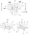
上述の様に止め輪20aを用い、前記内輪17を前記ピニオン軸6に対し支持固定する為、本例の場合には、先ず、この内輪17の軸方向片側からこのピニオン軸6の軸方向他半部を挿通する。そして、この内輪17をこのピニオン軸6の軸方向中間部の外周面に設けた前記嵌合面27に径方向に関するがたつきなく外嵌すると共に、前記内輪17の軸方向片端面を前記内径側段差面19に突き当てる。次に、前記ピニオン軸6の軸方向他端寄り部分を、円筒状の前記止め輪20aに軸方向片側から挿通する。本例の場合、この止め輪20aの軸方向片端面を、軸方向他側に向かうに従って内径が小さくなる方向に傾斜した傾斜面29としている。次いで、前記ピニオン軸6の軸方向他端寄り部分を、内周面のうちの軸方向片端寄り部分に、軸方向片側に向かう程内径が大きくなる方向に傾斜した傾斜面部30を設けたかしめ工具31の内径側に挿通する。そして、このかしめ工具31を軸方向片側に向け変位させる(押圧する)事により、前記傾斜面部30により前記止め輪20aを前記内輪17に向け押し付けつつ、この止め輪20aの軸方向他端寄り部分を縮径する方向に塑性変形させる。これにより、この止め輪20aの軸方向他端部を前記係止溝28に係止し(この止め輪20aの軸方向他端面をこの係止溝28の底面に押し付け)、この止め輪20aを、前記内輪17とこの係止溝28との間で突っ張らせる。
Since the retaining
本例の場合、この止め輪20aの軸方向片端面を前記傾斜面29としている為、前記押し付けに伴ってこの止め輪20aが、図3の(A)に矢印αで示す様に、この止め輪20aの軸方向片端面の外周縁を中心として、この止め輪20aの軸方向他端寄り部分が縮径する方向に傾く(塑性変形する)傾向になる。そして、図3の(B)→(C)に示す様に、前記かしめ工具31を更に軸方向片側に向け変位させ、このかしめ工具31の内周面に設けた前記傾斜面部30に沿って前記止め輪20aの軸方向他端寄り部分を縮径し(かしめ)、この止め輪20aの軸方向他端部を前記係止溝28に係止する。この止め輪20aの縮径作業の完了状態に於いては、前記内輪17の軸方向他端面と前記止め輪20aの軸方向片端面(傾斜面29)とは互いにほぼ平行(形状誤差に基づく僅かなずれを除く。)になり、これら両面同士が全周に亙り当接する。前記傾斜面29の、軸方向に対し直交する仮想平面に対する傾斜角度θは、前記縮径作業の完了状態に於いて、前記内輪17の軸方向他端面と前記止め輪20aの軸方向片端面とが互いにほぼ平行となる様に、この止め輪20aの軸方向長さや前記係止溝28の径方向深さ等に基づき、設計的に定める。又、本例の場合、前記かしめ工具31の傾斜面部30は、図2〜3、図4の(A)に示す様な、断面形状が部分円弧形の曲面としている。但し、前記傾斜面部30は、図4の(B)に示す様な、部分円すい面とする事もできる。何れにしても、この傾斜面部30の傾斜角度や軸方向長さ等の形状に就いても、前記傾斜面29の傾斜角度θと同様に、設計的に定める。
In the case of this example, since the one end surface in the axial direction of the retaining
上述の様な本例によれば、止め輪20aを縮径する(かしめる)のに要する力を低減できる。即ち、本例の場合、この止め輪20aの軸方向片端面を、軸方向他側に向かうに従って内径が小さくなる方向に傾斜した傾斜面29としている。この為、前記止め輪20aをかしめ工具31により、玉軸受16を構成する内輪17に向けて押し付ける事に伴い、前記止め輪20aの軸方向他端寄り部分が縮径する方向に傾く傾向になる。この為、この止め輪20aの軸方向他端寄り部分を縮径する(かしめる)のに要する力を低減でき、前記かしめ工具31を軸方向に押圧する押圧装置を小型化できる。又、上述の様に止め輪20aを縮径するのに要する力を低減できる構造を、この止め輪20aの軸方向片端面を前記傾斜面29とする事で実現しており、この止め輪20aの製造コストが徒に増大する事はない。従って、例えばピニオン軸6及び前記玉軸受16を組み込んだラックアンドピニオン式のステアリングギヤユニット5(図8〜10参照)の製造コストを低減できる。
According to this example as described above, it is possible to reduce the force required for reducing (caulking) the
又、本例の場合、前記止め輪20aの縮径作業の完了状態では、前記内輪17の軸方向他端面と前記止め輪20aの軸方向片端面(傾斜面29)とは互いにほぼ平行な状態になって、これら両面同士が全周、全幅に亙り当接する。この為、これら両面同士の当接面積を確保でき、前記ピニオン軸6に対する前記内輪17の保持力を確保できる。
In the case of this example, when the diameter reduction operation of the retaining
更に本例の場合には、前記内輪17の軸方向片端面を前記内径側段差面19に突き当てた状態での、この内輪17の軸方向他端面と前記係止溝28の軸方向他端縁との軸方向距離dと、前記止め輪20aの軸方向長さL20とをほぼ同じにしている。この為、この止め輪20aの縮径作業の途中段階で、図3の(B)に示す様に、この止め輪20aの軸方向他端部内周縁と、前記係止溝28の軸方向他端縁部とが干渉する(この止め輪20aの軸方向他端部内周縁がこの係止溝28の軸方向他端縁部に引っ掛かる)。この状態から前記かしめ工具31を軸方向片側に向かって変位させると、前記止め輪20aの軸方向片端部がこの止め輪20aの軸方向長さを縮める方向に塑性変形する(潰れる)。そして、前記かしめ工具31を更に軸方向片側に向かって変位させる事で、前記止め輪20aの軸方向他端部を前記係止溝28に係止する。本例の場合、この止め輪20aの軸方向片端面を前記傾斜面29とし、この止め輪20aの軸方向片端部の肉厚を小さくしている為、この軸方向片端部を塑性変形させる為に要する力を小さく抑えられる。更に、前記傾斜面29により前記止め輪20aの軸方向他端寄り部分が縮径する方向に傾く傾向となる為、この止め輪20aの軸方向他端部内周縁と、前記係止溝28の軸方向他端縁部との干渉を防止できる。この面からも前記止め輪20aを縮径するのに要する力の低減を図れる。又、この止め輪20aの軸方向片端部の肉厚を小さくする事で、塑性変形し易く(潰れ易く)している為、この止め輪20a及び前記係止溝28の軸方向長さに多少のばらつきが生じた場合でも、この止め輪20aの軸方向片端部を塑性変形させ、このばらつきを吸収する事ができる。
尚、図5に示す様に、止め輪20aの軸方向片端面の内外両周縁に面取り部32、32を設ければ、この止め輪20aの前記内輪17への押し付けに伴いこの内輪17の軸方向他端面が傷付くのを抑えられる。この様な面取り部32、32は、前記止め輪20aの軸方向片端面の両周縁のうち、何れか一方の周縁にのみ設ける事もできる。
Further, in the case of this example, the other end surface in the axial direction of the
As shown in FIG. 5, if
[実施の形態の第2例]
図6〜7は、請求項1、3に対応する、本発明の実施の形態の第2例を示している。本例の場合、内周面の軸方向片端寄り部分に軸方向片側に向かう程内径が大きくなる方向に傾斜した傾斜面部30a、30aをそれぞれ設けた1対のかしめ金型33、33により、止め輪20aの軸方向他端部外周縁を径方向に押圧する。これにより、前記両傾斜面部30a、30aに沿って、前記止め輪20aを内輪17に向け押し付けつつ、この止め輪20aの軸方向他端寄り部分を縮径する(かしめる)。
その他の部分の構成及び作用は、上述した実施の形態の第1例の場合と同様であるから、重複する図示並びに説明は省略する。
[Second Example of Embodiment]
6 to 7 show a second example of an embodiment of the present invention corresponding to claims 1 and 3 . In the case of this example, it is stopped by a pair of caulking dies 33 and 33 each provided with
Since the configuration and operation of other parts are the same as in the case of the first example of the embodiment described above, overlapping illustrations and descriptions are omitted.
上述した実施の形態の各例は、ピニオン軸に対し玉軸受の内輪を支持固定する場合に就いて説明した。これに対して、本発明は、回転軸或いは支持軸である軸に対し、玉軸受やころ軸受等の転がり軸受を構成する内輪を支持固定する場合に利用する事もできる。 Each example of embodiment mentioned above demonstrated about the case where the inner ring | wheel of a ball bearing is supported and fixed with respect to a pinion shaft. On the other hand, the present invention can also be used when an inner ring constituting a rolling bearing such as a ball bearing or a roller bearing is supported and fixed to a shaft that is a rotating shaft or a supporting shaft.
1 ステアリングホイール
2 ステアリングシャフト
3 自在継手
4 中間シャフト
5 ステアリングギヤユニット
6 ピニオン軸
7 ピニオン歯
8 ラック軸
9 ラック歯
10 ケーシング
11 主収納部
12 副収納部
13 球面継手
14 タイロッド
15 ラジアルニードル軸受
16 玉軸受
17 内輪
18 外輪
19 内径側段差面
20、20a 止め輪
21 外径側段差面
22 抑えねじ筒
23 シリンダ筒部
24 押圧ブロック
25 蓋体
26 ばね
27 嵌合面
28 係止溝
29 傾斜面
30、30a 傾斜面部
31 かしめ工具
32 面取り部
33 かしめ金型
DESCRIPTION OF SYMBOLS 1
Claims (3)
前記止め輪の軸方向片端面を、軸方向他側に向かうに従って内径が小さくなる方向に傾斜した傾斜面としており、
前記段差面に、前記内輪の軸方向片端面を突き当てた状態で、前記軸の軸方向他端寄り部分を前記止め輪に挿通した後、この止め輪の軸方向片端面を前記内輪の軸方向他端面に押し付けつつ、この止め輪の少なくとも軸方向他端寄り部分を縮径し、この止め輪の軸方向他端部を前記軸の外周面に形成した係止溝に係止する事により、この止め輪を前記内輪の軸方向他端面とこの係止溝との間で突っ張らせて、この内輪の軸方向変位を阻止する事を特徴とする転がり軸受用内輪の固定方法。 In order to support and fix the inner ring of the rolling bearing with respect to the shaft, the inner ring is separated from both sides in the axial direction by a stepped surface provided at the axially intermediate portion of the shaft and a retaining ring locked to the outer peripheral surface of the shaft. In the method of fixing the inner ring for the rolling bearing to be sandwiched,
The one end surface in the axial direction of the retaining ring is an inclined surface that is inclined in a direction in which the inner diameter becomes smaller toward the other side in the axial direction,
In a state where the one end surface in the axial direction of the inner ring is abutted against the stepped surface, a portion closer to the other end in the axial direction of the shaft is inserted into the retaining ring, and then the one end surface in the axial direction of the retaining ring is used as the shaft of the inner ring. By pressing at least the other axial end portion of the retaining ring while pressing against the other end surface in the direction, and engaging the other axial end portion of the retaining ring in a retaining groove formed on the outer peripheral surface of the shaft. A method for fixing an inner ring for a rolling bearing, wherein the retaining ring is stretched between the other axial end surface of the inner ring and the engaging groove to prevent axial displacement of the inner ring.
Priority Applications (1)
| Application Number | Priority Date | Filing Date | Title |
|---|---|---|---|
| JP2013267578A JP6287181B2 (en) | 2013-12-25 | 2013-12-25 | Fixing method of inner ring for rolling bearing |
Applications Claiming Priority (1)
| Application Number | Priority Date | Filing Date | Title |
|---|---|---|---|
| JP2013267578A JP6287181B2 (en) | 2013-12-25 | 2013-12-25 | Fixing method of inner ring for rolling bearing |
Publications (3)
| Publication Number | Publication Date |
|---|---|
| JP2015124787A JP2015124787A (en) | 2015-07-06 |
| JP2015124787A5 JP2015124787A5 (en) | 2016-12-01 |
| JP6287181B2 true JP6287181B2 (en) | 2018-03-07 |
Family
ID=53535643
Family Applications (1)
| Application Number | Title | Priority Date | Filing Date |
|---|---|---|---|
| JP2013267578A Active JP6287181B2 (en) | 2013-12-25 | 2013-12-25 | Fixing method of inner ring for rolling bearing |
Country Status (1)
| Country | Link |
|---|---|
| JP (1) | JP6287181B2 (en) |
Families Citing this family (2)
| Publication number | Priority date | Publication date | Assignee | Title |
|---|---|---|---|---|
| JP2019107989A (en) * | 2017-12-18 | 2019-07-04 | 株式会社ジェイテクト | Steering unit |
| DE102020215271A1 (en) * | 2020-12-03 | 2022-06-09 | Volkswagen Aktiengesellschaft | Method of locating a split inner ring on a shaft |
Family Cites Families (5)
| Publication number | Priority date | Publication date | Assignee | Title |
|---|---|---|---|---|
| US5971621A (en) * | 1998-05-04 | 1999-10-26 | Ford Motor Company | Axial shaft retention design |
| JP2007009940A (en) * | 2005-06-28 | 2007-01-18 | Nsk Ltd | Bearing fixing structure of steering device |
| JP2008057589A (en) * | 2006-08-29 | 2008-03-13 | Nsk Ltd | Parts fixing structure to shaft |
| JP2012180860A (en) * | 2011-02-28 | 2012-09-20 | Nsk Ltd | Bearing fixation structure |
| JP2012237403A (en) * | 2011-05-12 | 2012-12-06 | Nsk Ltd | Fixing structure, and method of bearing |
-
2013
- 2013-12-25 JP JP2013267578A patent/JP6287181B2/en active Active
Also Published As
| Publication number | Publication date |
|---|---|
| JP2015124787A (en) | 2015-07-06 |
Similar Documents
| Publication | Publication Date | Title |
|---|---|---|
| JP5017927B2 (en) | Electric power steering device | |
| JP5454371B2 (en) | Rack and pinion type steering gear unit and manufacturing method thereof | |
| EP1818242A2 (en) | Electric power steering apparatus | |
| WO2013005713A1 (en) | Bearing affixation structure and steering gear unit using bearing affixation structure | |
| JP2018024366A (en) | Steering device | |
| JP6287181B2 (en) | Fixing method of inner ring for rolling bearing | |
| JP2010064519A (en) | Rack shaft supporting device and vehicular steering device | |
| EP3132869A1 (en) | Method of making shaft | |
| JP5618146B2 (en) | Electric power steering device | |
| JP2012117648A (en) | Reduction gear, electric power steering device equipped with the same, and method of manufacturing reduction gear | |
| JP5626144B2 (en) | Steering device | |
| JP6471552B2 (en) | Retaining ring and worm reducer | |
| JP4168337B2 (en) | Spline fitting | |
| JP5526655B2 (en) | Electric power steering device | |
| JP2007057012A (en) | Rolling bearing device | |
| JP2007016951A (en) | Method for manufacturing telescopic shaft | |
| JP6171738B2 (en) | Tapered snap ring | |
| JP6845786B2 (en) | Power steering device | |
| JP5626162B2 (en) | Tapered snap ring fixing structure | |
| JP5958202B2 (en) | Manufacturing method of steering device | |
| JP2017218071A (en) | Rack-and-pinion type steering device, and method for manufacturing the same | |
| JP2005132287A (en) | Rack shaft support device, sealing member and its manufacturing method | |
| JP5392559B2 (en) | Rack shaft support device | |
| JP2016097792A (en) | Rack and pinion type steering gear unit | |
| JP2009160961A (en) | Rack-and-pinion type steering device, and method of forming sliding surface of guide member in the device |
Legal Events
| Date | Code | Title | Description |
|---|---|---|---|
| A521 | Request for written amendment filed |
Free format text: JAPANESE INTERMEDIATE CODE: A523 Effective date: 20161017 |
|
| A621 | Written request for application examination |
Free format text: JAPANESE INTERMEDIATE CODE: A621 Effective date: 20161017 |
|
| A977 | Report on retrieval |
Free format text: JAPANESE INTERMEDIATE CODE: A971007 Effective date: 20170713 |
|
| A131 | Notification of reasons for refusal |
Free format text: JAPANESE INTERMEDIATE CODE: A131 Effective date: 20170725 |
|
| A521 | Request for written amendment filed |
Free format text: JAPANESE INTERMEDIATE CODE: A523 Effective date: 20170905 |
|
| TRDD | Decision of grant or rejection written | ||
| A01 | Written decision to grant a patent or to grant a registration (utility model) |
Free format text: JAPANESE INTERMEDIATE CODE: A01 Effective date: 20180109 |
|
| A61 | First payment of annual fees (during grant procedure) |
Free format text: JAPANESE INTERMEDIATE CODE: A61 Effective date: 20180122 |
|
| R150 | Certificate of patent or registration of utility model |
Ref document number: 6287181 Country of ref document: JP Free format text: JAPANESE INTERMEDIATE CODE: R150 |
|
| R250 | Receipt of annual fees |
Free format text: JAPANESE INTERMEDIATE CODE: R250 |