JP2018024366A - Steering device - Google Patents
Steering device Download PDFInfo
- Publication number
- JP2018024366A JP2018024366A JP2016158349A JP2016158349A JP2018024366A JP 2018024366 A JP2018024366 A JP 2018024366A JP 2016158349 A JP2016158349 A JP 2016158349A JP 2016158349 A JP2016158349 A JP 2016158349A JP 2018024366 A JP2018024366 A JP 2018024366A
- Authority
- JP
- Japan
- Prior art keywords
- driven pulley
- lock nut
- notch
- screw
- pulley
- Prior art date
- Legal status (The legal status is an assumption and is not a legal conclusion. Google has not performed a legal analysis and makes no representation as to the accuracy of the status listed.)
- Granted
Links
- 238000005096 rolling process Methods 0.000 claims abstract description 73
- 210000000078 claw Anatomy 0.000 claims abstract description 55
- 230000002093 peripheral effect Effects 0.000 claims description 49
- 230000005540 biological transmission Effects 0.000 claims description 14
- 210000001217 buttock Anatomy 0.000 claims 1
- 239000000463 material Substances 0.000 description 13
- 230000004048 modification Effects 0.000 description 12
- 238000012986 modification Methods 0.000 description 12
- 238000000034 method Methods 0.000 description 8
- 230000000694 effects Effects 0.000 description 5
- 238000001514 detection method Methods 0.000 description 4
- 238000003825 pressing Methods 0.000 description 3
- 238000005452 bending Methods 0.000 description 2
- 238000004080 punching Methods 0.000 description 2
- 230000002159 abnormal effect Effects 0.000 description 1
- 230000015572 biosynthetic process Effects 0.000 description 1
- 230000008878 coupling Effects 0.000 description 1
- 238000010168 coupling process Methods 0.000 description 1
- 238000005859 coupling reaction Methods 0.000 description 1
- 230000005484 gravity Effects 0.000 description 1
- 230000035515 penetration Effects 0.000 description 1
- 230000001105 regulatory effect Effects 0.000 description 1
- 239000011347 resin Substances 0.000 description 1
- 229920005989 resin Polymers 0.000 description 1
- 230000009466 transformation Effects 0.000 description 1
Images


Classifications
-
- B—PERFORMING OPERATIONS; TRANSPORTING
- B62—LAND VEHICLES FOR TRAVELLING OTHERWISE THAN ON RAILS
- B62D—MOTOR VEHICLES; TRAILERS
- B62D5/00—Power-assisted or power-driven steering
- B62D5/04—Power-assisted or power-driven steering electrical, e.g. using an electric servo-motor connected to, or forming part of, the steering gear
- B62D5/0442—Conversion of rotational into longitudinal movement
- B62D5/0445—Screw drives
- B62D5/0448—Ball nuts
-
- B—PERFORMING OPERATIONS; TRANSPORTING
- B62—LAND VEHICLES FOR TRAVELLING OTHERWISE THAN ON RAILS
- B62D—MOTOR VEHICLES; TRAILERS
- B62D3/00—Steering gears
- B62D3/02—Steering gears mechanical
-
- B—PERFORMING OPERATIONS; TRANSPORTING
- B62—LAND VEHICLES FOR TRAVELLING OTHERWISE THAN ON RAILS
- B62D—MOTOR VEHICLES; TRAILERS
- B62D5/00—Power-assisted or power-driven steering
- B62D5/04—Power-assisted or power-driven steering electrical, e.g. using an electric servo-motor connected to, or forming part of, the steering gear
- B62D5/0421—Electric motor acting on or near steering gear
- B62D5/0424—Electric motor acting on or near steering gear the axes of motor and final driven element of steering gear, e.g. rack, being parallel
-
- F—MECHANICAL ENGINEERING; LIGHTING; HEATING; WEAPONS; BLASTING
- F16—ENGINEERING ELEMENTS AND UNITS; GENERAL MEASURES FOR PRODUCING AND MAINTAINING EFFECTIVE FUNCTIONING OF MACHINES OR INSTALLATIONS; THERMAL INSULATION IN GENERAL
- F16H—GEARING
- F16H25/00—Gearings comprising primarily only cams, cam-followers and screw-and-nut mechanisms
- F16H25/18—Gearings comprising primarily only cams, cam-followers and screw-and-nut mechanisms for conveying or interconverting oscillating or reciprocating motions
- F16H25/20—Screw mechanisms
- F16H25/22—Screw mechanisms with balls, rollers, or similar members between the co-operating parts; Elements essential to the use of such members
- F16H25/2204—Screw mechanisms with balls, rollers, or similar members between the co-operating parts; Elements essential to the use of such members with balls
-
- F—MECHANICAL ENGINEERING; LIGHTING; HEATING; WEAPONS; BLASTING
- F16—ENGINEERING ELEMENTS AND UNITS; GENERAL MEASURES FOR PRODUCING AND MAINTAINING EFFECTIVE FUNCTIONING OF MACHINES OR INSTALLATIONS; THERMAL INSULATION IN GENERAL
- F16H—GEARING
- F16H35/00—Gearings or mechanisms with other special functional features
- F16H35/18—Turning devices for rotatable members, e.g. shafts
-
- B—PERFORMING OPERATIONS; TRANSPORTING
- B62—LAND VEHICLES FOR TRAVELLING OTHERWISE THAN ON RAILS
- B62D—MOTOR VEHICLES; TRAILERS
- B62D5/00—Power-assisted or power-driven steering
- B62D5/04—Power-assisted or power-driven steering electrical, e.g. using an electric servo-motor connected to, or forming part of, the steering gear
- B62D5/0403—Power-assisted or power-driven steering electrical, e.g. using an electric servo-motor connected to, or forming part of, the steering gear characterised by constructional features, e.g. common housing for motor and gear box
-
- F—MECHANICAL ENGINEERING; LIGHTING; HEATING; WEAPONS; BLASTING
- F16—ENGINEERING ELEMENTS AND UNITS; GENERAL MEASURES FOR PRODUCING AND MAINTAINING EFFECTIVE FUNCTIONING OF MACHINES OR INSTALLATIONS; THERMAL INSULATION IN GENERAL
- F16B—DEVICES FOR FASTENING OR SECURING CONSTRUCTIONAL ELEMENTS OR MACHINE PARTS TOGETHER, e.g. NAILS, BOLTS, CIRCLIPS, CLAMPS, CLIPS OR WEDGES; JOINTS OR JOINTING
- F16B39/00—Locking of screws, bolts or nuts
- F16B39/02—Locking of screws, bolts or nuts in which the locking takes place after screwing down
- F16B39/025—Locking of screws, bolts or nuts in which the locking takes place after screwing down by plastic deformation of a part of one of the threaded elements into a notch or cavity of the other threaded element
-
- F—MECHANICAL ENGINEERING; LIGHTING; HEATING; WEAPONS; BLASTING
- F16—ENGINEERING ELEMENTS AND UNITS; GENERAL MEASURES FOR PRODUCING AND MAINTAINING EFFECTIVE FUNCTIONING OF MACHINES OR INSTALLATIONS; THERMAL INSULATION IN GENERAL
- F16H—GEARING
- F16H25/00—Gearings comprising primarily only cams, cam-followers and screw-and-nut mechanisms
- F16H25/18—Gearings comprising primarily only cams, cam-followers and screw-and-nut mechanisms for conveying or interconverting oscillating or reciprocating motions
- F16H25/20—Screw mechanisms
- F16H2025/2062—Arrangements for driving the actuator
- F16H2025/2081—Parallel arrangement of drive motor to screw axis
-
- F—MECHANICAL ENGINEERING; LIGHTING; HEATING; WEAPONS; BLASTING
- F16—ENGINEERING ELEMENTS AND UNITS; GENERAL MEASURES FOR PRODUCING AND MAINTAINING EFFECTIVE FUNCTIONING OF MACHINES OR INSTALLATIONS; THERMAL INSULATION IN GENERAL
- F16H—GEARING
- F16H25/00—Gearings comprising primarily only cams, cam-followers and screw-and-nut mechanisms
- F16H25/18—Gearings comprising primarily only cams, cam-followers and screw-and-nut mechanisms for conveying or interconverting oscillating or reciprocating motions
- F16H25/20—Screw mechanisms
- F16H2025/2062—Arrangements for driving the actuator
- F16H2025/2096—Arrangements for driving the actuator using endless flexible members
Landscapes
- Engineering & Computer Science (AREA)
- Mechanical Engineering (AREA)
- Chemical & Material Sciences (AREA)
- Combustion & Propulsion (AREA)
- Transportation (AREA)
- General Engineering & Computer Science (AREA)
- Power Steering Mechanism (AREA)
- Transmission Devices (AREA)
- Devices For Conveying Motion By Means Of Endless Flexible Members (AREA)
Abstract
Description
本発明は、ステアリング装置に関する。 The present invention relates to a steering device.
特許文献1には、電動モータの回転駆動力をボールネジ機構によって軸方向推力に変換し、ラックシャフトの作動を補助する電動パワーステアリング装置が記載されている。このステアリング装置では、電動モータのモータシャフトとラックシャフトとが、オフセットした位置に平行に配置されている。そして、電動モータの回転駆動力を伝達する従動プーリと、ボールネジ機構の転動体ナットとが、一体的に固定されている。
ここで、固定機構の一例としては、転動体ナットの外周面に形成された雄ネジを従動プーリの内周面に形成された雌ネジにねじ込み、その後、各ネジの端部にカシメを行なうものがある。カシメによって、螺着した各ネジを変形させて相対回転不能とするものである。 Here, as an example of the fixing mechanism, a male screw formed on the outer peripheral surface of the rolling element nut is screwed into a female screw formed on the inner peripheral surface of the driven pulley, and then the end of each screw is caulked. There is. Each screw that is screwed is deformed by caulking so that relative rotation is impossible.
特許文献2には、電動モータが備えるモータシャフトとラックシャフトとが、同軸に配置される方式のステアリング装置が記載されている。このステアリング装置では、モータシャフトとロックナットとが、一体的に固定されている。この固定機構では、まず、外周面に雄ねじが形成されたロックナットを、内周面に雌ねじが形成された中空状のモータシャフトにねじ込み、ロックナット端面がボールナットを軸方向に押圧して固定する。その後、ロックナットの端部に形成された薄壁部を、モータシャフトの一端部に形成された切欠きに向かって折り曲げ、且つ折り曲げを切欠きに係入させる。このようにして、ロックナットとモータシャフトとが、相対回転不能となる。
特許文献1に記載のステアリング装置において、カシメによる固定機構では、カシメ時において、カシメ部の近傍に位置する従動プーリの外周に形成された外歯が変形する虞がある。これにより、従動プーリとモータシャフトに固定される駆動プーリとの間に亘って掛け渡される歯付ベルトの作動時に異音が発生する、又は歯飛びが発生し伝達トルクが低下する虞がある。
In the steering device described in
仮に、特許文献1に示す方式のステアリング装置に、特許文献2の上記固定機構を適用する場合においても、従動プーリの外歯の変形には十分に注意する必要がある(第一の課題)。
Even when the above-described fixing mechanism of
また、特許文献1に示す方式のステアリング装置に、特許文献2の上記固定機構を適用する場合において、カシメに比べて、従動プーリと転動体ナットとの固定機構の部分が、軸線方向に大型化する虞がある。そうすると、従動プーリを囲むハウジングが大型化する(第二の課題)。
Further, when the above-described fixing mechanism of
本発明は、従動プーリと転動体ナットとの固定機構において、第一の課題及び第二の課題の少なくとも一方を解決することができるステアリング装置を提供することを目的とする。 An object of the present invention is to provide a steering device that can solve at least one of the first problem and the second problem in a fixing mechanism between a driven pulley and a rolling element nut.
本発明に係る第一態様のステアリング装置は、ハウジングに軸線方向に摺動可能に支承されており、前記軸線方向に往復移動し転舵輪を転舵させる転舵軸と、前記転舵軸の外周面に第一ネジ溝が形成される転動体ネジ部、前記第一ネジ溝に対応する第二ネジ溝が内周面に形成される転動体ナット、及び前記第一ネジ溝と前記第二ネジ溝との間に収容される複数の転動体を備えるボールネジ機構と、前記ハウジングに固定されており、前記転舵軸とオフセットした出力シャフトを備えるモータと、前記出力シャフトに一体回転可能に固定され外周に第一外歯が形成された駆動プーリ、前記転動体ナットの外側に設けられ外周に第二外歯が形成された従動プーリ、及び前記第一外歯及び前記第二外歯と内歯で噛合し前記駆動プーリ及び前記従動プーリの間で駆動力を伝達する歯付きベルトを備えるベルト伝達機構と、前記転動体ナットと前記従動プーリとの相対回転を規制する固定機構と、を備える。 A steering device according to a first aspect of the present invention is supported by a housing so as to be slidable in an axial direction, and reciprocates in the axial direction to steer a steered wheel, and an outer periphery of the steered shaft. A rolling element screw portion having a first screw groove formed on a surface thereof, a rolling element nut having a second screw groove corresponding to the first screw groove formed on an inner peripheral surface, and the first screw groove and the second screw A ball screw mechanism including a plurality of rolling elements housed between the grooves, a motor fixed to the housing, and an output shaft offset from the steered shaft, and fixed to the output shaft so as to be integrally rotatable. Driving pulley having first outer teeth formed on the outer periphery, driven pulley provided on the outer side of the rolling element nut and having second outer teeth formed on the outer periphery, and the first outer teeth and the second outer teeth and the inner teeth Meshed with the driving pulley and the driven pulley It comprises a belt transmission mechanism comprising a toothed belt for transmitting the driving force between the Li, a fixing mechanism for restricting the relative rotation between the driven pulley and the rolling elements nut, a.
前記固定機構は、前記従動プーリの内周面に形成された雌ネジと、前記従動プーリにおいて前記雌ネジより前記従動プーリの一端側に形成され、前記従動プーリの少なくとも径方向内方及び軸線方向端部側に開口する切欠部と、前記雌ネジに螺合する雄ネジを有するロックナット本体、及び、前記切欠部内に配置され前記従動プーリに対して周方向に係止される係止爪を備えるロックナットと、を備える。前記切欠部は、前記第二外歯の軸線方向範囲から外れた軸線方向位置に形成される。そして、前記ロックナットは、前記ロックナット本体と、前記ロックナット本体から前記軸線方向に延在し前記ロックナット本体より薄肉に形成された薄肉筒部の一部であって、径方向外方へ延在するように形成され、前記切欠部に対して周方向に係止される前記係止爪と、前記薄肉筒部の残部と、を備える。 The fixing mechanism includes a female screw formed on an inner peripheral surface of the driven pulley, and is formed on one end side of the driven pulley from the female screw in the driven pulley, and at least radially inward and axial direction of the driven pulley A lock nut body having a notch that opens to the end side, a male screw that is screwed into the female screw, and a locking claw that is disposed in the notch and is locked in the circumferential direction with respect to the driven pulley. A lock nut. The notch is formed at an axial position deviated from the axial range of the second external tooth. The lock nut is a part of the lock nut main body and a thin cylindrical portion that extends from the lock nut main body in the axial direction and is thinner than the lock nut main body, and is radially outward. The locking claw that is formed to extend and is locked in the circumferential direction with respect to the notch, and the remaining portion of the thin-walled cylinder.
このように、従動プーリの切欠部が、第二外歯の軸線方向範囲から外れた軸線方向位置に形成される。このため、係止爪と従動プーリにおける切欠部の周縁部分とが周方向に押圧しあい相対回転を規制する場合において、係止爪からの押圧力によって、第二外歯が変形する虞は小さい。 Thus, the notch part of a driven pulley is formed in the axial direction position which remove | deviated from the axial direction range of the 2nd external tooth. For this reason, when the locking claw and the peripheral portion of the notch portion of the driven pulley are pressed in the circumferential direction and the relative rotation is restricted, the possibility that the second external teeth are deformed by the pressing force from the locking claw is small.
また、本発明に係る第二態様のステアリング装置は、ハウジングに軸線方向に摺動可能に支承されており、前記軸線方向に往復移動し転舵輪を転舵させる転舵軸と、前記転舵軸の外周面に第一ネジ溝が形成される転動体ネジ部、前記第一ネジ溝に対応する第二ネジ溝が内周面に形成される転動体ナット、及び前記第一ネジ溝と前記第二ネジ溝との間に収容される複数の転動体を備えるボールネジ機構と、前記ハウジングに固定されており、前記転舵軸とオフセットした出力シャフトを備えるモータと、前記出力シャフトに一体回転可能に固定され外周に第一外歯が形成された駆動プーリ、前記転動体ナットの外側に設けられ外周に第二外歯が形成された従動プーリ、及び前記第一外歯及び前記第二外歯と内歯で噛合し前記駆動プーリ及び前記従動プーリの間で駆動力を伝達する歯付きベルトを備えるベルト伝達機構と、前記転動体ナットと前記従動プーリとの相対回転を規制する固定機構と、を備える。 The steering device according to the second aspect of the present invention is supported by the housing so as to be slidable in the axial direction, and reciprocates in the axial direction to steer the steered wheels, and the steered shaft. A rolling element screw portion in which a first screw groove is formed on an outer peripheral surface of the rolling element, a rolling element nut in which a second screw groove corresponding to the first screw groove is formed on an inner peripheral surface, and the first screw groove and the first A ball screw mechanism having a plurality of rolling elements housed between two screw grooves, a motor fixed to the housing and having an output shaft offset from the steered shaft, and integrally rotatable with the output shaft A drive pulley fixed and formed with first external teeth on the outer periphery, a driven pulley provided outside the rolling element nut and formed with second external teeth on the outer periphery, and the first external teeth and the second external teeth; Meshed with internal teeth, the drive pulley and the It comprises a belt transmission mechanism comprising a toothed belt for transmitting the driving force between the moving pulley, a fixing mechanism for restricting the relative rotation between the driven pulley and the rolling elements nut, a.
前記従動プーリは、前記第二外歯、及び、前記第二外歯より前記従動プーリの一端側に形成され前記歯付きベルトの前記軸線方向への移動を規制する鍔部を備える。前記固定機構は、前記従動プーリの内周面に形成された雌ネジと、前記従動プーリにおいて前記雌ネジより前記従動プーリの一端側に形成され、前記従動プーリの径方向内方及び軸線方向端部側に開口する切欠部と、前記雌ネジに螺合する雄ネジを有するロックナット本体、及び、前記切欠部に配置され前記従動プーリに対して周方向に係止される係止爪を備えるロックナットと、を備える。 The driven pulley includes a second outer tooth and a flange formed on one end side of the driven pulley from the second outer tooth to restrict movement of the toothed belt in the axial direction. The fixing mechanism includes a female screw formed on an inner peripheral surface of the driven pulley, and is formed on one end side of the driven pulley with respect to the female screw in the driven pulley. A lock nut body having a notch opening to the side, a male screw threadedly engaged with the female screw, and a locking claw disposed in the notch and circumferentially locked to the driven pulley. A lock nut.
前記切欠部は、前記鍔部の前記軸線方向の範囲内において、前記鍔部の径方向内方に形成され、又は前記第二外歯、及び、前記鍔部の前記軸線方向の範囲内において、前記第二外歯、及び、前記鍔部の径方向内方に形成される。そして、前記ロックナットは、前記ロックナット本体と、前記ロックナット本体から前記軸線方向に延在し前記ロックナット本体より薄肉に形成された薄肉筒部の一部であって、径方向外方へ延在するように形成され、前記切欠部内に配置される前記係止爪と前記薄肉筒部の残部と、を備える。 The notch is formed radially inward of the flange in the axial range of the flange, or in the axial direction of the second external tooth and the flange, The second outer teeth are formed on the radially inner side of the flange portion. The lock nut is a part of the lock nut main body and a thin cylindrical portion that extends from the lock nut main body in the axial direction and is thinner than the lock nut main body, and is radially outward. The locking claw that is formed so as to extend and is disposed in the cutout portion and the remaining portion of the thin tube portion.
このように、従動プーリの切欠部が、鍔部、又は、第二外歯及び鍔部の軸線方向の範囲内において、鍔部、又は、第二外歯及び鍔部の径方向内方に形成される。このため、ロックナットの係止爪は、第二外歯及び鍔部の軸線方向の範囲内に位置する。従って、ロックナットの係止爪による固定機構を適用したとしても、従動プーリは、係止爪と係止するための構造部分によって軸線方向に延びることはない。結果として、ロックナットを介することによる従動プーリと転動体ナットとの確実な固定が可能となると共に、ステアリング装置の大型化を抑制できる。 Thus, the notch portion of the driven pulley is formed in the radial direction inward of the flange portion or the second external tooth and the flange portion within the axial direction range of the flange portion or the second external tooth and the flange portion. Is done. For this reason, the latching claw of the lock nut is located within the axial range of the second external teeth and the collar portion. Therefore, even if the fixing mechanism using the locking claw of the lock nut is applied, the driven pulley does not extend in the axial direction by the structural portion for locking with the locking claw. As a result, the driven pulley and the rolling element nut can be securely fixed via the lock nut, and the size of the steering device can be suppressed.
<1.第一実施形態>
(1−1.概要)
以下、本発明のステアリング装置の実施形態について図面を参照しつつ説明する。ステアリング装置の一例として、車両用の電動パワーステアリング装置について説明する。電動パワーステアリング装置は、モータMによる操舵補助力によって操舵力を補助するステアリング装置である。なお、ステアリング装置は、電動パワーステアリング装置の他に、4輪操舵装置、後輪操舵装置、ステアバイワイヤ装置などでもよい。
<1. First embodiment>
(1-1. Overview)
Hereinafter, embodiments of a steering device of the present invention will be described with reference to the drawings. As an example of the steering device, an electric power steering device for a vehicle will be described. The electric power steering device is a steering device that assists the steering force by the steering assist force of the motor M. The steering device may be a four-wheel steering device, a rear wheel steering device, a steer-by-wire device, or the like in addition to the electric power steering device.
(1−2.電動パワーステアリング装置の構成)
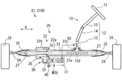
図1に示すように、電動パワーステアリング装置S1(以降、ステアリング装置S1とのみ称す)は、操舵機構10、転舵機構20、操舵補助機構30、固定機構40及びトルク検出装置50を有する。操舵機構10は、ステアリングホイール11、及びステアリングシャフト12を備える。ステアリングホイール11は、ステアリングシャフト12の端部に固定される。ステアリングシャフト12は、転舵輪26,26を転舵するためステアリングホイール11に加えられる操舵トルクを伝達する。
(1-2. Configuration of electric power steering device)
As shown in FIG. 1, the electric power steering device S <b> 1 (hereinafter referred to only as the steering device S <b> 1) includes a
ステアリングシャフト12は、コラム軸13、中間軸14、及びピニオン軸15を連結して構成される。ピニオン軸15の入力側部分には、中間軸14の出力側部分が接続され、出力側部分には、ピニオン歯15dが形成される。
The steering
転舵機構20は、ラックシャフト21(転舵軸に相当)、及び略円筒状に形成されたハウジング22を有する。ラックシャフト21は、ステアリングホイール11の操舵角度に応じて軸線方向に往復移動し、車両の転舵輪26,26を転舵させる。ラックシャフト21は、軸線方向に沿って直線往復移動可能(摺動可能)にハウジング22に収容されて支承される。
The
以下の説明において、ラックシャフト21の軸線方向に沿った方向を単に「A軸方向(図1参照)」とも称する。ハウジング22は、第一ハウジング22a、及び第一ハウジング22aのA軸方向他端側(図1中、左側)に固定された第二ハウジング22bを備える。第一ハウジング22aは、主にラックシャフト21を収容する。第二ハウジング22bは、主に操舵補助機構30に係る装置を収容する。なお、以降において、図1における右側を一端側とし、左側を他端側として説明する。
In the following description, the direction along the axial direction of the
ラックシャフト21の外周面には、ラック歯21aが形成される。ラック歯21a及びピニオン歯15dは、互いに噛合されて、ラックアンドピニオン機構を構成する。また、ラックシャフト21は、両端部にジョイント27,27を有する。ジョイント27,27の両端部には、タイロッド24,24が連結される。タイロッド24,24の先端は、転舵輪26,26が組み付けられた図示しないナックルに連結される。
これにより、ステアリングホイール11が操舵されると、その操舵トルクが、ステアリングシャフト12に伝達されピニオン軸15が回転される。ピニオン軸15の回転は、ピニオン歯15d及びラック歯21aによって、ラックシャフト21の直線往復移動に変換される。このA軸方向に沿った移動がタイロッド24,24を介してナックル(図略)に伝達されることにより、転舵輪26,26が転舵され、車両の進行方向が変更される。
Thus, when the
ハウジング22の両端には、ブーツ25,25の一端部が固定される。ブーツ25,25は、樹脂製で、ジョイント27,27とタイロッド24,24とのジョイント部分を覆い、A軸方向に伸縮可能な筒状の蛇腹部を有する。ブーツ25,25の他端部はタイロッド24,24に固定される。
At both ends of the
操舵補助機構30は、トルク検出装置50の出力に基づいて制御されるモータMを駆動源として操舵機構10に操舵補助力を付与する機構である。操舵補助機構30は、MCU(モータコントロールユニット)、出力シャフト32、ボールネジ機構33、及びベルト伝達機構35を備える。操舵補助機構30は、第二ハウジング22b、及び第三ハウジング31に収容される。
The
図1に示すように、操舵補助機構30では、制御部ECUとモータMを一体化したMCUが、ラックシャフト21よりも下側(重力方向下方)に配置される。このように、本実施形態のステアリング装置S1は、所謂、ラックパラレル型の電動ステアリング装置として構成され、車両前方のエンジンルーム内(車室外)に配置される。
As shown in FIG. 1, in the steering assist
(1−3.操舵補助機構)
図2に示すように、操舵補助機構30は、モータMの回転トルクを、ベルト伝達機構35を介してボールネジ機構33に伝達する。そして、ボールネジ機構33で、回転トルクをラックシャフト21の直線往復動の移動力に変換し、操舵機構10に操舵補助力を付与する。
(1-3. Steering assist mechanism)
As shown in FIG. 2, the steering assist
モータMを含むMCUは、第三ハウジング31内に収容される。MCUは、ラックシャフト21と離間してハウジング22に取り付けられる。そして、モータMの出力シャフト32がハウジング22内に延在するよう配置される。このとき、図2に示すように、出力シャフト32の軸線は、ラックシャフト21の軸線と平行(オフセットに相当)となるよう設けられる。出力シャフト32は、プレート36の貫通孔に、軸受313を介して回転可能に支持される。
The MCU including the motor M is accommodated in the
ベルト伝達機構35は、駆動プーリ35a、歯付きベルト35b、及び従動プーリ35cを備える。ベルト伝達機構35は、歯付きベルト35bを介して駆動プーリ35aと従動プーリ35cとの間で、モータMが発生させる駆動力(回転駆動力)を伝達する機構である。
The
図2に示すように、駆動プーリ35aは、出力シャフト32に一体回転可能に固定され、外周に第一外歯35a1が形成される。歯付きベルト35bは、内歯35b1を内周側に複数有する円環状のゴムベルトである。歯付きベルト35bは、従動プーリ35cの外周と駆動プーリ35aの外周との間で、各外周に設けられた第一外歯35a1及び第二外歯35c1と内歯35b1が噛合した状態で掛け渡される。
As shown in FIG. 2, the
歯付きベルト35bは、従動プーリ35c及び駆動プーリ35aとの噛合が外れ、歯飛びが起きないように、所定の張力を有した状態で駆動プーリ35aと従動プーリ35cとの間に掛け渡される。従動プーリ35cは、プーリ本体35c4と、鍔部35c5と、を備える円筒状の部材である。
The
図2に示すように、従動プーリ35c(プーリ本体35c4)の径方向内方には、第一孔35A、及び、第二孔35Bが、プーリ本体35c4の外周面と同軸で形成される。第一孔35Aは、従動プーリ35cの他端側に設けられる。第二孔35Bは、従動プーリ35cの一端側に設けられる。第一孔35Aの内径は、第二孔35Bの内径よりも小さい。
As shown in FIG. 2, a
第一孔35Aと第二孔35Bとの境界には段差Bが形成される。段差Bが有する径方向に形成される接続面B1が、第二孔35Bの開口35B1側に向いている。また、第二孔35Bの内周面には、雌ネジ41が形成されている。
A step B is formed at the boundary between the
図2に示すように、第一孔35Aが形成する空間には、転動体ナット33aが収容される。このとき、段差Bの接続面B1には、転動体ナット33aの一端側に拡径されて形成されるフランジ部33a2の他端側の端面が当接する。
As shown in FIG. 2, the rolling
第二孔35Bにより形成される空間には、フランジ部33a2及び円環状のロックナット42(固定機構40)が配置される。ロックナット42の外周に形成された雄ネジ42dは、第二孔35Bの内周面に形成された雌ネジ41に螺合する。
A flange portion 33a2 and an annular lock nut 42 (fixing mechanism 40) are disposed in the space formed by the
本実施形態において、鍔部35c5は、従動プーリ35cと別体で環状に形成される。鍔部35c5は、従動プーリ35c(プーリ本体35c4)の第二外歯35c1の両側にそれぞれ圧入して固定される。
In the present embodiment, the flange 35c5 is formed in a ring shape separately from the driven
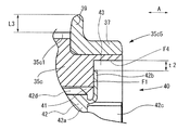
詳細には、図4に示すように、鍔部35c5は、円筒状に形成された円筒部37と、円筒部37の軸線方向の一方の端部に円筒部37の径方向外方に拡径する円環状の円環部39を備えて形成される。つまり、鍔部35c5は、従動プーリ35cの軸線を含む平面で切断すると、断面がL字状に形成される。L字の一辺は円筒部37であり、L字の他辺は、円環部39である。円筒部37の内周面が、従動プーリ35cの第二外歯35c1の両側の外周面に圧入される。
Specifically, as shown in FIG. 4, the
また、鍔部35c5の円環部39は、プーリ本体35c4が有する第二外歯35c1の軸線方向両側の径方向外方に、第二外歯35c1から長さL3だけ突出するよう設けられる(図3参照)。長さL3は、モータM、及び駆動プーリ35aが回転作動し、これに伴って歯付きベルト35bが作動した場合に、歯付きベルト35bが、従動プーリ35cの外周面から軸線方向(A軸方向)に移動し従動プーリ35cから脱落することを防止可能とする長さである。なお、従動プーリ35cは、転動体ナット33aとの間で固定機構40により相対回転不能に固定される。
Further, the
上記の構成により、操舵補助機構30は、ステアリングホイール11の回転操作に応じてモータMを駆動し、出力シャフト32及び駆動プーリ35aを回転させる。駆動プーリ35aの回転は、歯付きベルト35bを介して従動プーリ35cに伝達される。従動プーリ35cが回転することにより、従動プーリ35cと一体的に固定される転動体ナット33aが回転される。そして、転動体ナット33aが回転されることにより、ボールネジ機構33を介してラックシャフト21の軸線方向への操舵補助力(動力)がラックシャフト21に伝達される。
With the above configuration, the steering assist
トルク検出装置50は、ピニオン軸15の中間部に設けられた図略のトーションバーの捩れ量を検出し、捩れ量に応じた信号を制御部ECUに出力する。制御部ECUは、トルク検出装置50の出力信号に基づいて、操舵補助トルクを決定し、モータMの出力を制御する。
The
ボールネジ機構33は、ベルト伝達機構35を介して伝達されたモータMの回転トルクを、ラックシャフト21の直線往復動の移動力に変換することで操舵機構10に操舵補助力を付与する機構である。図2に示すように、ボールネジ機構33は、ボールネジ部21b(転動体ネジ部に相当)と、転動体ナット33aと、図略の連結部材と、複数のボール38(転動体に相当)と、を備える。
The
ボールネジ部21bは、ラックシャフト21の外周面に、A軸方向に沿った一定範囲に亘って形成される。ボールネジ部21bには、第一ネジ溝21b1が形成される。第一ネジ溝21b1は、ラックシャフト21の外周面に所定のリード(ピッチ)で形成された螺旋状の溝である。
The
前述したように、転動体ナット33aは、径方向においてボールネジ部21bの外側、及び、従動プーリ35cの内側に配置される円筒状部材である。前述したように転動体ナット33aは、図2における一端側の端部に、フランジ部33a2を備える。そしてフランジ部33a2の図2における他端側端面が段差Bの接続面B1と当接する。これにより、軸線方向において転動体ナット33aが従動プーリ35cに対して位置決めされる。
As described above, the rolling
転動体ナット33aは、上述したように、従動プーリ35cに対して軸線方向の位置が位置決めされた状態で、第二ハウジング22bにボールベアリング16を介して支持される。また、転動体ナット33aの一端側では、後に詳述する本発明に係る固定機構40が転動体ナット33aと従動プーリ35cとを一体回転可能に固定する。
As described above, the rolling
また、転動体ナット33aは、内周面に第二ネジ溝33a1を備える。第二ネジ溝33a1は、ボールネジ部21bの第一ネジ溝21b1に対応する溝である。第二ネジ溝33a1は、ボールネジ部21bの第一ネジ溝21b1と対向して形成され、第一ネジ溝21b1のリードと同じリードで形成された螺旋状の溝である。
The rolling
第一ネジ溝21b1と、第二ネジ溝33a1とによって、螺旋軌道(図略)が形成される。詳細には、第一ネジ溝21b1の溝面及び第二ネジ溝33a1の溝面と各溝面の間の空間とによって複数のボール38(転動体)が収容される螺旋軌道が形成される。 A spiral track (not shown) is formed by the first screw groove 21b1 and the second screw groove 33a1. Specifically, a spiral track in which a plurality of balls 38 (rolling elements) are accommodated is formed by the groove surface of the first screw groove 21b1, the groove surface of the second screw groove 33a1, and the space between the groove surfaces.
螺旋軌道では、転動体ナット33aがラックシャフト21に対して相対回転すると、複数のボール38(転動体に相当)が螺旋軌道を転動する。そして、螺旋軌道を転動した複数のボール38は、図略の連結部材によって転動体ナット33a内の通路に誘導されたのち、転動体ナット33a内に形成された通路を移動し、やがて図略の連結部材によって螺旋軌道に戻される。なお、このような、ボールネジ機構は公知の技術であるので、これ以上の詳細な説明は省略する。
In the spiral track, when the rolling
(1−4.固定機構40の構成)
次に、本発明に係る固定機構40の構成について説明する。固定機構40は、上述したように、転動体ナット33a、及び、従動プーリ35cの各一端側において、転動体ナット33aと従動プーリ35cとを一体回転可能に固定し、転動体ナット33aと従動プーリ35cとの間の相対回転を規制する機構である。
(1-4. Configuration of the fixing mechanism 40)
Next, the configuration of the
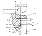
図4に示すように、固定機構40は、従動プーリ35cに設けられる雌ネジ41と、ロックナット42と、従動プーリ35cに設けられる切欠部43と、を備える。雌ネジ41は、前述したように、従動プーリ35cの一端側に形成された第二孔35Bの内周面に設けられる。
As shown in FIG. 4, the fixing
切欠部43は、従動プーリ35cの一端側(図3の右側)、即ちプーリ本体35c4の一端側において、図4に示すように、プーリ本体35c4の端部の周方向に所定の幅T1を有して貫通し形成される(貫通形成に相当)。つまり、本実施形態において、切欠部43は、従動プーリ35c(プーリ本体35c4)の径方向内方側、軸線方向端部側及び径方向外方側の三方に開口して形成される空間である。従って、切欠部43は、その周囲に配置される、プーリ本体35c4が備える底面F1、及び対向する側面F2、F3と接している(図3,図4参照)。
The
このとき、切欠部43は、プーリ本体35c4の端部の周方向において回転位相が180度異なる任意の位置に、二箇所設けられる。なお、二箇所に設けられた切欠部43は、同じ形状で形成されるものである。よって、以降における切欠部43の説明は、いずれか一方の切欠部43のみについて行なう。
At this time, the
ただし、切欠部43は、二箇所には限らない。切欠部43は、プーリ本体35c4の端部の周方向において、一箇所だけ設けてもよいし、3箇所以上設けてもよい。なお、切欠部43を、3箇所以上設ける場合、周方向において等角度(等位相)間隔で形成されることが好ましい。
However, the
切欠部43は、図3に示すように、第二外歯35c1の軸線方向範囲(A軸方向における範囲)から外れた軸線方向位置に形成される。つまり、図3において、切欠部43は、第二外歯35c1の軸線方向範囲の端部であるP部よりも右方向に外れて形成される。
As shown in FIG. 3, the
また、切欠部43は、鍔部35c5のA軸方向の範囲C内において、鍔部35c5の径方向内方に形成されている(図4参照)。そして、前述した鍔部35c5は、切欠部43の径方向外方の開口を閉塞する。
Further, the
このとき、本実施形態においては、鍔部35c5における円筒部37の内周にプーリ本体35c4を圧入した圧入部位の軸線方向における圧入長さL1は、円筒部37の軸線方向における全長の概ね半分程度である。ただしこの寸法は任意に設定すればよい。よって、長さL2で形成される円筒部37の残りの部分が、切欠部43の径方向外方における開口を閉塞するとともに、切欠部43が形成されていないプーリ本体35c4の残りの外周面に圧入され固定される。
At this time, in this embodiment, the press-fitting length L1 in the axial direction of the press-fitting site where the pulley body 35c4 is press-fitted into the inner periphery of the
ロックナット42は、固定機構40を構成する際に、図6Aに示すロックナット素材42AAの一部を変形させて形成される部材である。ロックナット素材42AAは、ロックナット本体42a、及び薄肉筒部Tbを備える。
The
ロックナット本体42aは、外周面に従動プーリ35cが備える雌ネジ41に螺合する雄ネジ42dを有する。ロックナット本体42aはA軸方向において、円筒状に形成される。薄肉筒部Tbは、円筒状に形成されたロックナット本体42aの一端側からA軸方向にロックナット本体42aと同軸で円筒状に延在し形成される。
The lock nut
薄肉筒部Tbは、ロックナット本体42aより薄肉に形成される。薄肉筒部Tbの肉厚(板厚)は、例えば、0.5mm前後である。ただし、この薄肉筒部Tbの肉厚(板厚)はあくまで一例であり、この数値に限定されるものではない。ロックナット素材42AAの円筒内の空間には、ラックシャフト21が挿通される。
The thin tube portion Tb is formed thinner than the lock nut
ロックナット素材42AAから形成されるロックナット42は、ロックナット本体42a、係止爪42b、及び残部42cを備える。係止爪42b、及び残部42cは、薄肉筒部Tbから形成される。薄肉筒部Tbの一部である係止爪42bは、薄肉筒部Tbの残部42cの径方向外方へ延在して形成される。
The
係止爪42bは、係止爪42bの径方向外方に配置される切欠部43に係入される(図3,図4参照)。このとき、係止爪42bの径方向外方の先端は、切欠部43の径方向外方において、切欠部43の開口を閉塞する鍔部35c5の円筒部37の内周面に対して隙間t1を有する位置に位置する。これにより、係止爪42bの形成時に、係止爪42bの先端が円筒部37に当接せず、円筒部37(鍔部35c5)が固定された従動プーリ35cを押圧しないため、第二外歯35c1を変形させる虞はない。また、係止爪42b自身が変形する虞もない。
The locking
なお、このとき、係止爪42bの周方向における幅T2は、切欠部43の周方向における幅T1よりわずかに小さい大きさであることが好ましい。これにより、係止爪42bが切欠部43に係入された際、係止爪42bが切欠部43に対して周方向にほぼ隙間なく係止される。つまり、係止爪42bを備えるロックナット42と、切欠部43を備える従動プーリ35cと、の間において周方向における相対移動が良好に規制される。このため、ロックナット42が従動プーリ35cに対して相対回転してロックナット42に緩みが生じることを確実に抑制できる。また、本実施形態においては、ロックナット42の残部42cの一端側における端面は、従動プーリ35cの一端側の端面より図3において右側に出ないように形成される。
At this time, the width T2 in the circumferential direction of the locking
(1−5.固定機構40の組付方法)
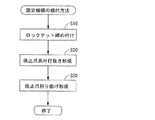
次に、固定機構40の組付方法について主に図5のフローチャート,及び図6A−図6Cに基づき説明する。固定機構40の組付方法は、第一工程S10〜第三工程S30を備える。
(1-5. Assembly method of fixing mechanism 40)
Next, an assembling method of the
第一工程S10(螺着工程、図5参照)では、転動体ナット33aを、図2に示すように、転動体ナット33aのフランジ部33a2の他端側端面が接続面B1に当接するまで、第一孔35Aの他端側に向かって挿入する。その後、図6Aに示す状態のロックナット素材42AAの外周に形成された雄ネジ42dと、第二孔35Bの内周面に形成された雌ネジ41とを螺合させてロックナット素材42AAをねじ込む。これにより、ロックナット素材42AAの転動体ナット33a側の端面42eが、転動体ナット33aの端面に当接する。また、これによって、転動体ナット33aを他端側方向に押圧する押圧状態として、転動体ナット33aを従動プーリ35c(プーリ本体35c4)に固定する。
In the first step S10 (screwing step, see FIG. 5), the rolling
第二工程S20(打ち抜き工程、図5参照)では、ロックナット素材42AAを、従動プーリ35cに締めこんだ状態で係止爪42bの係止爪素材42BBを形成する(図6B参照)。つまり、成り行きによって、従動プーリ35cの切欠部43と対向する、ロックナット素材42AAが備える薄肉筒部Tbの外周面の一部を、図略の打ち抜き型によって、屈曲部Dを残して切欠部43側に向かって打ち抜く。これにより、係止爪素材42BBを形成する。なお、このとき、係止爪素材42BBの周方向における幅はT2である。
In the second step S20 (punching step, see FIG. 5), the locking claw material 42BB of the locking
第三工程S30(屈曲工程、図5参照)では、係止爪素材42BBを、屈曲部Dを支点として、周方向における幅がT1(T1≧T2)である切欠部43に係入させながら軸線に対し、約90度折り曲げる。これにより、係止爪42bが形成されるとともにロックナット42が形成され固定機構40の組付けが完了する(図6Cに示す状態となる)。これにより、ロックナット42が従動プーリ35cに対して相対回転してロックナット42に緩みが生じることを確実に抑制する。
In the third step S30 (bending step, see FIG. 5), the engaging claw material 42BB is engaged with the
なお、このとき、係止爪42bの先端は上述したように、切欠部43の径方向外方において、切欠部43の開口を閉塞する鍔部35c5の円筒部37の内周面に対して隙間t1を有する位置に位置する(図4参照)。これにより、係止爪42bが円筒部37に当接せず、延いては円筒部37及びプーリ本体35c4を押圧しないため、第二外歯35c1を変形させる虞もない。また、係止爪42bが切欠部43と接するプーリ本体35c4の底面F1を押圧しても、底面F1は、第二外歯35c1の軸線方向範囲から外れた軸線方向位置に形成されているので、第二外歯35c1を変形させる虞は低い。
At this time, as described above, the front end of the locking
<2.変形例>
(2−1.変形例1)
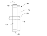
また、上記実施形態では、切欠部43は、プーリ本体35c4(従動プーリ35c)の一端側において、プーリ本体35c4の端部の周方向に所定の幅T1で貫通し形成されるものとして説明した。しかし、この態様には限らない。第一実施形態の変形例1として、切欠部43は、図7に示すように、プーリ本体35c4の一端側において、径方向に貫通していなくてもよい。
<2. Modification>
(2-1. Modification 1)
Moreover, in the said embodiment, the
つまり、切欠部43は、プーリ本体35c4(従動プーリ35c)において、プーリ本体35c4の径方向内方側、及び軸線方向端部側の二方に開口して形成される空間であってもよい。従って、このとき切欠部43は、その周囲に、プーリ本体35c4が備える底面F1、及び対向する側面F2、F3及び、切欠部43の内周面F4(即ち、従動プーリ35cの内周面)と接している。
That is, the
そして、このとき、切欠部43の係止爪42bの径方向外方の先端は、従動プーリの内周面(切欠部43の内周面F4)に対して隙間t2を有する位置に位置する。これにより、係止爪42bの形成時に、係止爪42bの先端が鍔部35c5の円筒部37に当接せず、円筒部37及び従動プーリ35cを押圧しないため、第二外歯35c1を変形させる虞はない。また、係止爪42b自身が変形する虞もない。
At this time, the radially outward tip of the locking
(2−2.変形例2)
また、上記実施形態では、鍔部35c5は、従動プーリ35cの軸線方向両端に従動プーリ35cと別体で環状に形成されるものとして説明した。しかし、この態様には限らない。第一実施形態の変形例2(図略)として、従動プーリ35cの軸線方向における端部の何れか一方は、鍔部35c5が、従動プーリ35cと別体ではなく一体で形成されてもよい。これによっても、上記実施形態と同様の効果が期待できる。
(2-2. Modification 2)
Moreover, in the said embodiment, the collar part 35c5 demonstrated as what was formed in an annular | circular shape separately from the driven
(2−3.変形例3)
また、上記実施形態の態様に限らず、第一実施形態の変形例3として、図8に示すように、切欠部43を、第二外歯35c1、及び、鍔部35c5のA軸方向における範囲外に形成してもよい。これにより、軸線方向への伸長はあるが、第二外歯35c1の変形に対して大きな効果が得られる。なお、このとき、切欠部43は、図8に示す形状に限らず、従動プーリ35cの径方向外方に貫通していてもよい。
(2-3. Modification 3)
Moreover, not only the aspect of the said embodiment but as a modification 3 of 1st embodiment, as shown in FIG. 8, the range in the A-axis direction of the 2nd external tooth 35c1 and the collar part 35c5 is shown. You may form outside. Thereby, although there exists expansion | extension to an axial direction, a big effect is acquired with respect to a deformation | transformation of the 2nd external tooth 35c1. At this time, the
<3.第二実施形態>
次に、第二実施形態について図9に基づき説明する。第二実施形態のステアリング装置S100(図1参照)は、第一実施形態のステアリング装置S1に対して、軸線方向において切欠部143が設けられる範囲のみが異なる。よって、第一実施形態に対して異なる部分のみについて説明し、同様の部分については、説明を省略する。また、同様の構成部分については同じ符号を付して説明する。
<3. Second embodiment>
Next, a second embodiment will be described based on FIG. The steering device S100 (see FIG. 1) of the second embodiment differs from the steering device S1 of the first embodiment only in the range in which the
第二実施形態のステアリング装置S100では、図9に示すように、固定機構140の切欠部143は、従動プーリ135cにおいて雌ネジ141より従動プーリ135cの一端側(図9において右側)に形成され、従動プーリ135cの径方向内方及びA軸方向端部側に開口する。また、切欠部143は、第二外歯135c1、及び、鍔部135c5のA軸方向の範囲内において、第二外歯135c1、及び、鍔部135c5の径方向内方に形成される。
In the steering device S100 of the second embodiment, as shown in FIG. 9, the
これにより、ロックナット142が、軸線方向に延在する残部142cを備えても、従動プーリ135cを、軸線方向に伸長させることなく成立させることができる。このため、軸線方向において大型化が抑制されたステアリング装置S100が実現できる。なお、固定機構140の組付け方法については、第一実施形態で説明した固定機構40の組付け方法と同じである。
Thereby, even if the
<4.実施形態による効果>
上述の説明から明らかなように、上記第一実施形態及び各変形例によれば、ステアリング装置S1は、ハウジング22に軸線方向に摺動可能に支承されており、軸線方向に往復移動し転舵輪26,26を転舵させるラックシャフト21(転舵軸)と、ラックシャフト21の外周面に第一ネジ溝21b1が形成されるボールネジ部21b(転動体ネジ部)、第一ネジ溝21b1に対応する第二ネジ溝33a1が内周面に形成される転動体ナット33a、及び第一ネジ溝21b1と第二ネジ溝33a1との間に収容される複数のボール38(転動体)を備えるボールネジ機構33と、ハウジング22に固定されており、ラックシャフト21とオフセットした出力シャフト32を備えるモータMと、出力シャフト32に一体回転可能に固定され外周に第一外歯35a1が形成された駆動プーリ35a、転動体ナット33aの外側に設けられ外周に第二外歯35c1が形成された従動プーリ35c、及び第一外歯35a1及び第二外歯35c1と内歯35b1で噛合し駆動プーリ35a及び従動プーリ35cの間で駆動力を伝達する歯付きベルト35bを備えるベルト伝達機構35と、転動体ナット33aと従動プーリ35cとの相対回転を規制する固定機構40と、を備える。
<4. Effects according to the embodiment>
As is clear from the above description, according to the first embodiment and each of the modified examples, the steering device S1 is supported on the
固定機構40は、従動プーリ35cの内周面に形成された雌ネジ41と、従動プーリ35cにおいて雌ネジ41より従動プーリ35cの一端側に形成され、従動プーリ35cの少なくとも径方向内方及び軸線方向端部側に開口する切欠部43と、雌ネジ41に螺合する雄ネジ42dを有するロックナット本体42a、及び、切欠部43内に配置され従動プーリ35cに対して周方向に係止される係止爪42bを備えるロックナット42と、を備える。
The fixing
そして、切欠部43は、第二外歯35c1の軸線方向範囲から外れた軸線方向位置に形成され、ロックナット42は、ロックナット本体42aと、ロックナット本体42aから軸線方向に延在しロックナット本体42aより薄肉に形成された薄肉筒部Tbの一部であって、径方向外方へ延在するように形成され、切欠部43に対して周方向に係止される係止爪42bと、薄肉筒部Tbの残部42cと、を備える。
The
このように、従動プーリ35cの切欠部43が、第二外歯35c1の軸線方向範囲から外れた軸線方向位置に形成される。このため、ロックナット42の薄肉筒部Tbの係止爪42bが折り曲げられ、且つ従動プーリ35cの切欠部43に係入された状態において、係止爪42bと、切欠部43の周縁における従動プーリ35cの側面F2,F3の所定の部分とが当接し、相互に周方向に押圧しあい相対回転を規制しても、第二外歯35c1が押圧による力を直接受け変形する虞は小さい。これにより、ボールネジ機構33の転動体ナット33aと、モータMの回転を伝達する従動プーリ35cとが変形することなく、確実に固定可能となる。
Thus, the
また、このとき、係止爪42bの先端は上述したように、切欠部43の径方向外方において切欠部43の開口を閉塞する鍔部35c5の円筒部37の内周面に対して隙間t1,t2を有する位置に位置する。これにより、係止爪42bを形成する組付けの際において、係止爪42bが円筒部37に当接せず、円筒部37及びプーリ本体35c4を押圧しないため、第二外歯35c1を変形させる虞もない。また、同様に組付けの際、係止爪42bが切欠部43と接するプーリ本体35c4の底面F1を押圧しても、底面F1は、第二外歯35c1の軸線方向範囲から外れた軸線方向位置に形成されているので、第二外歯35c1を変形させる虞は低い。
At this time, as described above, the tip of the locking
また、上記第一実施形態、変形例1、及び変形例2によれば、従動プーリ35cは、第二外歯35c1、及び、第二外歯35c1より従動プーリ35cの一端側に形成され歯付きベルト35bの軸線方向への移動を規制する鍔部35c5を備える。切欠部43は、鍔部35c5の軸線方向の範囲内において、鍔部35c5の径方向内方に形成される。これにより、従動プーリ35cの軸線方向への伸長を抑制しながら、上記実施形態と同様の効果が得られる。
Further, according to the first embodiment, the first modification, and the second modification, the driven
また、上記第一実施形態、変形例1、及び変形例2によれば、係止爪42bの径方向外方の先端は、従動プーリ35cの内周面に対して隙間t2を有する位置に位置する。これにより、上記実施形態と同様の効果が得られる。
Further, according to the first embodiment, the first modification, and the second modification, the distal end of the locking
また、上記第一実施形態によれば、ステアリング装置S1において、従動プーリ35cは、第二外歯35c1、及び、第二外歯35c1より従動プーリ35cの一端側に形成され径方向に貫通形成された切欠部43を備えるプーリ本体35c4と、プーリ本体35c4とは別体に環状に形成され、切欠部43の径方向外方の開口を閉塞するようにプーリ本体35c4に取り付けられる鍔部35c5と、を備える。そして、係止爪42bの径方向外方の先端は、鍔部35c5の内周面に対して隙間t1を有する位置に位置する。このように、切欠部43を径方向に貫通形成するので、簡易かつ低コストで切欠部43が形成できる。
Further, according to the first embodiment, in the steering device S1, the driven
上記第二実施形態によれば、ステアリング装置S100は、ハウジング22に軸線方向に摺動可能に支承されており、軸線方向に往復移動し転舵輪26,26を転舵させるラックシャフト21(転舵軸)と、ラックシャフト21の外周面に第一ネジ溝21b1が形成されるボールネジ部21b(転動体ネジ部)、第一ネジ溝21b1に対応する第二ネジ溝33a1が内周面に形成される転動体ナット33a、及び第一ネジ溝21b1と第二ネジ溝33a1との間に収容される複数のボール38(転動体)を備えるボールネジ機構33と、ハウジング22に固定されており、ラックシャフト21とオフセットした出力シャフト32を備えるモータMと、出力シャフト32に一体回転可能に固定され外周に第一外歯135a1が形成された駆動プーリ35a、転動体ナット33aの外側に設けられ外周に第二外歯35c1が形成された従動プーリ135c、及び第一外歯35a1及び第二外歯135c1と内歯35b1で噛合し駆動プーリ35a及び従動プーリ135cの間で駆動力を伝達する歯付きベルト35bを備えるベルト伝達機構35と、転動体ナット33aと従動プーリ135cとの相対回転を規制する固定機構140と、を備える。
According to the second embodiment, the steering device S100 is supported by the
従動プーリ135cは、第二外歯135c1、及び、第二外歯135c1より従動プーリ135cの一端側に形成され歯付きベルト35bの軸線方向への移動を規制する鍔部35c5を備える。そして、固定機構140は、従動プーリ135cの内周面に形成された雌ネジ141と、従動プーリ135cにおいて雌ネジ141より従動プーリ135cの一端側に形成され、従動プーリ135cの径方向内方及び軸線方向端部側に開口する切欠部143と、雌ネジ141に螺合する雄ネジ142dを有するロックナット本体142a、及び、切欠部143に配置され従動プーリ135cに対して周方向に係止される係止爪142bを備えるロックナット142と、を備える。
The driven
そして、切欠部143は、第二外歯135c1、及び、鍔部35c5の軸線方向の範囲内において、第二外歯135c1、及び、鍔部35c5の径方向内方に形成され、ロックナット142は、ロックナット本体142aと、ロックナット本体142aから軸線方向に延在しロックナット本体142aより薄肉に形成された薄肉筒部Tbの一部であって、径方向外方へ延在するように形成され、切欠部143内に配置される係止爪142bと、薄肉筒部Tbの残部142cと、を備える。
And the
このように、従動プーリ135cの切欠部143が、第二外歯135c1、及び、鍔部35c5の軸線方向の範囲内において、第二外歯135c1、及び、鍔部35c5の径方向内方に形成される。このため、新たに固定機構を設け、ロックナットを用いても、ステアリング装置S100は、軸線方向に延びることなく、小型のステアリング装置を実現させることができる。
In this way, the
21・・・ラックシャフト(転舵軸)、 21b・・・ボールネジ部(転動体ネジ部)、 21b1・・・第一ネジ溝、 22・・・ハウジング、 26・・・転舵輪、 32・・・出力シャフト、 33・・・ボールネジ機構、 33a・・・転動体ナット、 33a1・・・第二ネジ溝、 33a2・・・フランジ部、 35・・・ベルト伝達機構、 35a・・・駆動プーリ、 35a1・・・第一外歯、 35b・・・歯付きベルト、 35c・・・従動プーリ、 35c1,135c1・・・第二外歯、 35c4・・・プーリ本体、 35c5・・・鍔部、 38・・・ボール(転動体)、 40・・・固定機構、 41,141・・・雌ネジ、 42,142・・・ロックナット、 42a,142a・・・ロックナット本体、 42b,142b・・・係止爪、 42c,142c・・・残部、 42d,142d・・・雄ネジ、 43,143・・・切欠部、 M・・・モータ、 S1,S100・・・ステアリング装置(電動パワーステアリング装置)、 Tb・・・薄肉筒部。 21 ... Rack shaft (steering shaft), 21b ... Ball screw part (rolling element screw part), 21b1 ... First screw groove, 22 ... Housing, 26 ... Steering wheel, 32 ... -Output shaft, 33 ... Ball screw mechanism, 33a ... Rolling element nut, 33a1 ... Second screw groove, 33a2 ... Flange, 35 ... Belt transmission mechanism, 35a ... Drive pulley, 35a1 ... first external teeth, 35b ... toothed belt, 35c ... driven pulley, 35c1, 135c1 ... second external teeth, 35c4 ... pulley body, 35c5 ... collar, 38 ... Ball (rolling element), 40 ... Fixing mechanism, 41, 141 ... Female thread, 42, 142 ... Lock nut, 42a, 142a ... Lock nut body, 42b, 14 2b ... locking claw, 42c, 142c ... remaining, 42d, 142d ... male screw, 43, 143 ... notch, M ... motor, S1, S100 ... steering device (electric) Power steering device), Tb ... Thin-walled cylinder part.
Claims (5)
前記転舵軸の外周面に第一ネジ溝が形成される転動体ネジ部、前記第一ネジ溝に対応する第二ネジ溝が内周面に形成される転動体ナット、及び前記第一ネジ溝と前記第二ネジ溝との間に収容される複数の転動体を備えるボールネジ機構と、
前記ハウジングに固定されており、前記転舵軸とオフセットした出力シャフトを備えるモータと、
前記出力シャフトに一体回転可能に固定され外周に第一外歯が形成された駆動プーリ、前記転動体ナットの外側に設けられ外周に第二外歯が形成された従動プーリ、及び前記第一外歯及び前記第二外歯と内歯で噛合し前記駆動プーリ及び前記従動プーリの間で駆動力を伝達する歯付きベルトを備えるベルト伝達機構と、
前記転動体ナットと前記従動プーリとの相対回転を規制する固定機構と、
を備え、
前記固定機構は、
前記従動プーリの内周面に形成された雌ネジと、
前記従動プーリにおいて前記雌ネジより前記従動プーリの一端側に形成され、前記従動プーリの少なくとも径方向内方及び軸線方向端部側に開口する切欠部と、
前記雌ネジに螺合する雄ネジを有するロックナット本体、及び、前記切欠部内に配置され前記従動プーリに対して周方向に係止される係止爪を備えるロックナットと、を備え、
前記切欠部は、前記第二外歯の軸線方向範囲から外れた軸線方向位置に形成され、
前記ロックナットは、
前記ロックナット本体と、
前記ロックナット本体から前記軸線方向に延在し前記ロックナット本体より薄肉に形成された薄肉筒部の一部であって、径方向外方へ延在するように形成され、前記切欠部に対して周方向に係止される前記係止爪と、
前記薄肉筒部の残部と、
を備える、ステアリング装置。 A steering shaft that is slidably supported in the axial direction on the housing, reciprocates in the axial direction, and steers the steered wheels; and
A rolling element screw portion in which a first screw groove is formed on the outer peripheral surface of the steered shaft, a rolling element nut in which a second screw groove corresponding to the first screw groove is formed on an inner peripheral surface, and the first screw A ball screw mechanism comprising a plurality of rolling elements housed between a groove and the second screw groove;
A motor fixed to the housing and having an output shaft offset from the steered shaft;
A driving pulley fixed to the output shaft so as to be integrally rotatable and having first outer teeth formed on the outer periphery, a driven pulley provided on the outer side of the rolling element nut and having second outer teeth formed on the outer periphery, and the first outer A belt transmission mechanism comprising a toothed belt that meshes with teeth and the second external teeth and internal teeth and transmits a driving force between the drive pulley and the driven pulley;
A fixing mechanism for restricting relative rotation between the rolling element nut and the driven pulley;
With
The fixing mechanism is
A female screw formed on the inner peripheral surface of the driven pulley;
A notch formed at one end of the driven pulley from the female screw in the driven pulley and opening at least radially inward and axially end of the driven pulley;
A lock nut body having a male screw threadably engaged with the female screw, and a lock nut having a locking claw disposed in the notch and locked in the circumferential direction with respect to the driven pulley,
The notch is formed at an axial position deviated from the axial range of the second external tooth,
The lock nut is
The lock nut body;
A part of a thin cylindrical portion that extends from the lock nut body in the axial direction and is thinner than the lock nut body, and is formed so as to extend radially outward, with respect to the notch The locking claw locked in the circumferential direction,
The remainder of the thin tube portion;
A steering apparatus comprising:
前記切欠部は、前記鍔部の前記軸線方向の範囲内において、前記鍔部の径方向内方に形成される、請求項1に記載のステアリング装置。 The driven pulley includes the second external teeth, and a flange that is formed on one end side of the driven pulley from the second external teeth and restricts movement of the toothed belt in the axial direction.
The steering device according to claim 1, wherein the notch is formed radially inward of the flange within a range of the flange in the axial direction.
前記第二外歯、及び、前記第二外歯より前記従動プーリの一端側に形成され径方向に貫通形成された前記切欠部を備えるプーリ本体と、
前記プーリ本体とは別体に環状に形成され、前記切欠部の径方向外方の開口を閉塞するように前記プーリ本体に取り付けられる前記鍔部と、
を備え、
前記係止爪の径方向外方の先端は、前記鍔部の内周面に対して隙間を有する位置に位置する、請求項2に記載のステアリング装置。 The driven pulley is
A pulley body comprising the second outer teeth, and the notch portion formed on one end side of the driven pulley from the second outer teeth and formed in a radial direction,
The collar portion that is annularly formed separately from the pulley body, and is attached to the pulley body so as to close the radially outward opening of the notch,
With
The steering device according to claim 2, wherein a distal end of the locking claw in the radial direction is located at a position having a gap with respect to an inner peripheral surface of the flange portion.
前記転舵軸の外周面に第一ネジ溝が形成される転動体ネジ部、前記第一ネジ溝に対応する第二ネジ溝が内周面に形成される転動体ナット、及び前記第一ネジ溝と前記第二ネジ溝との間に収容される複数の転動体を備えるボールネジ機構と、
前記ハウジングに固定されており、前記転舵軸とオフセットした出力シャフトを備えるモータと、
前記出力シャフトに一体回転可能に固定され外周に第一外歯が形成された駆動プーリ、前記転動体ナットの外側に設けられ外周に第二外歯が形成された従動プーリ、及び前記第一外歯及び前記第二外歯と内歯で噛合し前記駆動プーリ及び前記従動プーリの間で駆動力を伝達する歯付きベルトを備えるベルト伝達機構と、
前記転動体ナットと前記従動プーリとの相対回転を規制する固定機構と、
を備え、
前記従動プーリは、前記第二外歯、及び、前記第二外歯より前記従動プーリの一端側に形成され前記歯付きベルトの前記軸線方向への移動を規制する鍔部を備え、
前記固定機構は、
前記従動プーリの内周面に形成された雌ネジと、
前記従動プーリにおいて前記雌ネジより前記従動プーリの一端側に形成され、前記従動プーリの径方向内方及び軸線方向端部側に開口する切欠部と、
前記雌ネジに螺合する雄ネジを有するロックナット本体、及び、前記切欠部に配置され前記従動プーリに対して周方向に係止される係止爪を備えるロックナットと、
を備え、
前記切欠部は、前記鍔部の前記軸線方向の範囲内において、前記鍔部の径方向内方に形成され、又は前記第二外歯、及び、前記鍔部の前記軸線方向の範囲内において、前記第二外歯、及び、前記鍔部の径方向内方に形成され、
前記ロックナットは、
前記ロックナット本体と、
前記ロックナット本体から前記軸線方向に延在し前記ロックナット本体より薄肉に形成された薄肉筒部の一部であって、径方向外方へ延在するように形成され、前記切欠部内に配置される前記係止爪と、
前記薄肉筒部の残部と、
を備える、ステアリング装置。 A steering shaft that is slidably supported in the axial direction on the housing, reciprocates in the axial direction, and steers the steered wheels; and
A rolling element screw portion in which a first screw groove is formed on the outer peripheral surface of the steered shaft, a rolling element nut in which a second screw groove corresponding to the first screw groove is formed on an inner peripheral surface, and the first screw A ball screw mechanism comprising a plurality of rolling elements housed between a groove and the second screw groove;
A motor fixed to the housing and having an output shaft offset from the steered shaft;
A driving pulley fixed to the output shaft so as to be integrally rotatable and having first outer teeth formed on the outer periphery, a driven pulley provided on the outer side of the rolling element nut and having second outer teeth formed on the outer periphery, and the first outer A belt transmission mechanism comprising a toothed belt that meshes with teeth and the second external teeth and internal teeth and transmits a driving force between the drive pulley and the driven pulley;
A fixing mechanism for restricting relative rotation between the rolling element nut and the driven pulley;
With
The driven pulley includes the second external teeth, and a flange that is formed on one end side of the driven pulley from the second external teeth and restricts movement of the toothed belt in the axial direction.
The fixing mechanism is
A female screw formed on the inner peripheral surface of the driven pulley;
A notch formed on one end of the driven pulley from the female screw in the driven pulley, and opened to a radially inner side and an axial end of the driven pulley;
A lock nut main body having a male screw threadably engaged with the female screw, and a lock nut provided with a locking claw disposed in the notch portion and locked in the circumferential direction with respect to the driven pulley;
With
The notch is formed radially inward of the flange in the axial range of the flange, or in the axial direction of the second external tooth and the flange, The second outer teeth and the inner side in the radial direction of the buttocks,
The lock nut is
The lock nut body;
A part of a thin cylindrical portion that extends in the axial direction from the lock nut body and is thinner than the lock nut body, and is formed so as to extend radially outward and is disposed in the notch portion. The locking claw being
The remainder of the thin tube portion;
A steering apparatus comprising:
Priority Applications (4)
| Application Number | Priority Date | Filing Date | Title |
|---|---|---|---|
| JP2016158349A JP6790572B2 (en) | 2016-08-12 | 2016-08-12 | Steering device |
| US15/667,756 US10232872B2 (en) | 2016-08-12 | 2017-08-03 | Steering apparatus |
| CN201710665771.6A CN107719464B (en) | 2016-08-12 | 2017-08-07 | Steering device |
| EP17185748.5A EP3290293B1 (en) | 2016-08-12 | 2017-08-10 | Steering apparatus |
Applications Claiming Priority (1)
| Application Number | Priority Date | Filing Date | Title |
|---|---|---|---|
| JP2016158349A JP6790572B2 (en) | 2016-08-12 | 2016-08-12 | Steering device |
Publications (2)
| Publication Number | Publication Date |
|---|---|
| JP2018024366A true JP2018024366A (en) | 2018-02-15 |
| JP6790572B2 JP6790572B2 (en) | 2020-11-25 |
Family
ID=59581791
Family Applications (1)
| Application Number | Title | Priority Date | Filing Date |
|---|---|---|---|
| JP2016158349A Active JP6790572B2 (en) | 2016-08-12 | 2016-08-12 | Steering device |
Country Status (4)
| Country | Link |
|---|---|
| US (1) | US10232872B2 (en) |
| EP (1) | EP3290293B1 (en) |
| JP (1) | JP6790572B2 (en) |
| CN (1) | CN107719464B (en) |
Cited By (1)
| Publication number | Priority date | Publication date | Assignee | Title |
|---|---|---|---|---|
| US11072362B2 (en) | 2018-04-12 | 2021-07-27 | Jtekt Corporation | Vehicle steering system |
Families Citing this family (5)
| Publication number | Priority date | Publication date | Assignee | Title |
|---|---|---|---|---|
| FR3028717B1 (en) * | 2014-11-25 | 2017-03-31 | Pellenc Sa | ELECTROPORTATIVE TOOL WITH PROTECTED TRANSMISSION. |
| CN111615482B (en) * | 2018-01-18 | 2022-10-25 | Zf主动安全和电子美国有限责任公司 | Device for steering steerable vehicle wheels |
| DE102019115542A1 (en) * | 2018-06-08 | 2019-12-12 | Steering Solutions Ip Holding Corporation | SERVICEABLE AGGREGATE BELT DRIVE |
| US10995799B2 (en) * | 2019-04-02 | 2021-05-04 | Steering Solutions Ip Holding Corporation | Self-retaining pulley for steering assembly |
| JP7322725B2 (en) * | 2020-01-29 | 2023-08-08 | 株式会社ジェイテクト | steering device |
Family Cites Families (9)
| Publication number | Priority date | Publication date | Assignee | Title |
|---|---|---|---|---|
| JP4311122B2 (en) | 2003-08-06 | 2009-08-12 | 株式会社ジェイテクト | Electric power steering device |
| JP5798946B2 (en) * | 2012-02-24 | 2015-10-21 | カヤバ工業株式会社 | Electric power steering device and shaft coupler used therefor |
| JP5962295B2 (en) | 2012-07-24 | 2016-08-03 | 株式会社ジェイテクト | Electric power steering device |
| US20140034410A1 (en) * | 2012-07-31 | 2014-02-06 | GM Global Technology Operations LLC | Rack Electric Power Steering Travel End Stops |
| JP6148121B2 (en) * | 2013-08-30 | 2017-06-14 | 日立オートモティブシステムズ株式会社 | Power steering device |
| JP2015047997A (en) | 2013-09-03 | 2015-03-16 | 日立オートモティブシステムズステアリング株式会社 | Power steering device and manufacturing method for power steering device |
| KR102126228B1 (en) * | 2014-02-06 | 2020-06-25 | 주식회사 만도 | Motor and Electric power steering apparatus having the same |
| KR20160096163A (en) * | 2014-02-27 | 2016-08-12 | 히다치 오토모티브 시스템즈 가부시키가이샤 | Power steering device and method for manufacturing ball screw for power steering device |
| US10730545B2 (en) | 2015-02-03 | 2020-08-04 | Jtekt Corporation | Steering apparatus |
-
2016
- 2016-08-12 JP JP2016158349A patent/JP6790572B2/en active Active
-
2017
- 2017-08-03 US US15/667,756 patent/US10232872B2/en active Active
- 2017-08-07 CN CN201710665771.6A patent/CN107719464B/en not_active Expired - Fee Related
- 2017-08-10 EP EP17185748.5A patent/EP3290293B1/en not_active Not-in-force
Cited By (1)
| Publication number | Priority date | Publication date | Assignee | Title |
|---|---|---|---|---|
| US11072362B2 (en) | 2018-04-12 | 2021-07-27 | Jtekt Corporation | Vehicle steering system |
Also Published As
| Publication number | Publication date |
|---|---|
| EP3290293B1 (en) | 2019-03-27 |
| US10232872B2 (en) | 2019-03-19 |
| CN107719464B (en) | 2021-11-23 |
| EP3290293A1 (en) | 2018-03-07 |
| US20180043927A1 (en) | 2018-02-15 |
| JP6790572B2 (en) | 2020-11-25 |
| CN107719464A (en) | 2018-02-23 |
Similar Documents
| Publication | Publication Date | Title |
|---|---|---|
| JP2018024366A (en) | Steering device | |
| US20180297628A1 (en) | Steering system | |
| US10661824B2 (en) | Steering system | |
| US10196084B2 (en) | Rack assist type electric power steering apparatus | |
| EP2711575A1 (en) | Rotation transmitting apparatus, vehicle steering system, and intermediate shaft | |
| US20190264751A1 (en) | Torque transmission joint and electric power steering device | |
| JP5003412B2 (en) | Torque transmission joint and electric power steering device | |
| US9926002B2 (en) | Housing structure and power steering apparatus | |
| JP2007040315A (en) | Power transmission mechanism and electric power steering device with the built-in power transmission mechanism | |
| JP6277895B2 (en) | Torque transmission member and coupling portion between drive shaft and driven shaft | |
| JP6471552B2 (en) | Retaining ring and worm reducer | |
| JP2008290593A (en) | Steering angle ratio variable steering device | |
| US20180172134A1 (en) | Worm reducer and electric assist device | |
| JP5526655B2 (en) | Electric power steering device | |
| JP2015124774A (en) | Disk spring and electrically-driven power steering device | |
| JP6364823B2 (en) | Electric power steering apparatus and manufacturing method thereof | |
| JP2015168306A5 (en) | ||
| JP2009214804A (en) | Electric power steering device | |
| JP2019086010A (en) | Seal ring and telescopic shaft | |
| JP6287181B2 (en) | Fixing method of inner ring for rolling bearing | |
| JP2018155301A (en) | Method for manufacturing worm reducer, worm reducer, and electric power steering device | |
| JP2005205923A (en) | Electric power steering device | |
| JP4775629B2 (en) | Ball screw mechanism | |
| JP4775219B2 (en) | Electric power steering device | |
| JP2008195310A (en) | Electric power steering device |
Legal Events
| Date | Code | Title | Description |
|---|---|---|---|
| A621 | Written request for application examination |
Free format text: JAPANESE INTERMEDIATE CODE: A621 Effective date: 20190716 |
|
| A977 | Report on retrieval |
Free format text: JAPANESE INTERMEDIATE CODE: A971007 Effective date: 20200520 |
|
| A131 | Notification of reasons for refusal |
Free format text: JAPANESE INTERMEDIATE CODE: A131 Effective date: 20200602 |
|
| A521 | Request for written amendment filed |
Free format text: JAPANESE INTERMEDIATE CODE: A523 Effective date: 20200729 |
|
| TRDD | Decision of grant or rejection written | ||
| A01 | Written decision to grant a patent or to grant a registration (utility model) |
Free format text: JAPANESE INTERMEDIATE CODE: A01 Effective date: 20201006 |
|
| A61 | First payment of annual fees (during grant procedure) |
Free format text: JAPANESE INTERMEDIATE CODE: A61 Effective date: 20201019 |
|
| R150 | Certificate of patent or registration of utility model |
Ref document number: 6790572 Country of ref document: JP Free format text: JAPANESE INTERMEDIATE CODE: R150 |