JP6287160B2 - Recording device - Google Patents
Recording device Download PDFInfo
- Publication number
- JP6287160B2 JP6287160B2 JP2013260964A JP2013260964A JP6287160B2 JP 6287160 B2 JP6287160 B2 JP 6287160B2 JP 2013260964 A JP2013260964 A JP 2013260964A JP 2013260964 A JP2013260964 A JP 2013260964A JP 6287160 B2 JP6287160 B2 JP 6287160B2
- Authority
- JP
- Japan
- Prior art keywords
- mounting portion
- mounting
- container
- recording apparatus
- ink
- Prior art date
- Legal status (The legal status is an assumption and is not a legal conclusion. Google has not performed a legal analysis and makes no representation as to the accuracy of the status listed.)
- Active
Links
Images


Landscapes
- Ink Jet (AREA)
Description
本発明は、記録装置に関する。 The present invention relates to a recording apparatus.
従来から、液体収容装置に収容された液体としてのインクを被記録媒体に吐出して記録
する記録装置が使用されている。このような記録装置のうち、インクを収容したインクカ
ートリッジ等の収容体を、記録ヘッドが設けられたホルダー等の装着部に、装着させる構
成の、液体収容装置を備えるものが多く使用されている。
例えば、特許文献1には、収容体としてのインクカートリッジと該インクカートリッジ
の装着部としてのヘッドホルダーとを有する液体収容装置を備えた記録装置が開示されて
いる。
また、近年、インクカートリッジ等の収容体及びその装着部に、様々な情報の入出力を
可能にする接続部が設けられた液体収容装置が使用されている。
2. Description of the Related Art Conventionally, a recording apparatus that uses ink as liquid stored in a liquid storage apparatus to be recorded on a recording medium has been used. Among such recording apparatuses, many are equipped with a liquid storage apparatus having a configuration in which a container such as an ink cartridge containing ink is mounted on a mounting section such as a holder provided with a recording head. .
For example,
In recent years, a liquid storage device in which a container such as an ink cartridge and a mounting portion thereof are provided with a connection portion that enables input and output of various information has been used.
上記のように、近年、収容体及びその装着部に、様々な情報の入出力を可能にする接続
部が設けられた液体収容装置が使用されているが、接続部(接続端子)間の接点不良等、
収容体を装着部に装着した際に不具合が発生する場合があった。
なお、特許文献1に開示される記録装置においては、接続部間の接点不良等の、収容体
を装着部に装着した際の不具合に関する記載はなく、該不具合を抑制できる構成にはなっ
ていなかった。
As described above, in recent years, a liquid storage device in which a connecting portion that enables input and output of various information is used in the container and its mounting portion has been used, but the contact point between the connecting portions (connection terminals) Defects, etc.
When the container is mounted on the mounting portion, a problem may occur.
In addition, in the recording apparatus disclosed in
そこで、本発明の目的は、接続部を有し液体を収容する収容体を、前記接続部と接続可
能な接続部と前記液体の導入部とを有する前記収容体の装着部に、装着した際の、不具合
を抑制することである。
SUMMARY OF THE INVENTION Accordingly, an object of the present invention is to mount a container having a connection part and containing a liquid on a mounting part of the container having a connection part connectable to the connection part and the liquid introduction part. It is to suppress the trouble.
上記課題を解決するための本発明の第1の態様の記録装置は、第1接続部を有し、液体
を収容する収容体を装着し、前記第1接続部と電気的に接続可能な第2接続部と、前記液
体を導入する導入部と、前記導入部から導出された前記液体を吐出し、被記録媒体に記録
を行う記録ヘッドと、を有する装着部と、前記装着部が取り付けられて移動するキャリッ
ジと、を備えることを特徴とする。
A recording apparatus according to a first aspect of the present invention for solving the above-described problem has a first connecting portion, is attached with a container that contains a liquid, and can be electrically connected to the first connecting portion. A mounting portion having two connecting portions, an introduction portion for introducing the liquid, and a recording head that discharges the liquid derived from the introduction portion and performs recording on a recording medium; and the attachment portion is attached. And a carriage that moves.
本態様によれば、前記収容体が装着される前記装着部に、前記収容体に設けられる前記
第1接続部と接続される前記第2接続部が設けられる。このため、装着部と被装着部とに
接続部が設けられる構成となり、前記第2接続部が前記装着部以外に設けられる構成、例
えば、前記第2接続部が前記キャリッジに設けられる構成等よりも、前記第1接続部と前
記第2接続部との間の接点不良等を抑制することができる。すなわち、前記収容体を前記
装着部に装着した際の不具合を抑制することができる。
According to this aspect, the second connecting portion connected to the first connecting portion provided in the housing is provided in the mounting portion to which the housing is mounted. For this reason, it becomes the structure by which a connection part is provided in a mounting part and a to-be-mounted part, and the structure where the said 2nd connection part is provided in addition to the said mounting part, for example, the structure where the said 2nd connection part is provided in the said carriage Moreover, the contact failure etc. between the said 1st connection part and the said 2nd connection part can be suppressed. That is, the trouble at the time of mounting the container on the mounting portion can be suppressed.
本発明の第2の態様の記録装置は、前記第1の態様において、前記装着部は、該装着部
に対する前記収容体の位置を決める第1位置決め部を有し、前記第1位置決め部は、3次
元方向に位置決めすることを特徴とする。
The recording apparatus according to a second aspect of the present invention is the recording apparatus according to the first aspect, wherein the mounting portion includes a first positioning portion that determines a position of the container with respect to the mounting portion. It is characterized by positioning in a three-dimensional direction.
本態様によれば、前記第1位置決め部により前記装着部に対する前記収容体の位置が3
次元方向に決められる。このため、前記収容体を前記装着部に対して適切な位置に固定で
きることで、前記第1接続部と前記第2接続部との間の接点不良等を抑制することができ
る。すなわち、効果的に前記収容体を前記装着部に装着した際の不具合を抑制することが
できる。
According to this aspect, the position of the container relative to the mounting portion is 3 by the first positioning portion.
It is determined in the dimension direction. For this reason, the contact body between the said 1st connection part and the said 2nd connection part etc. can be suppressed because the said container can be fixed to an appropriate position with respect to the said mounting part. That is, the malfunction at the time of mounting | wearing the said mounting body to the said mounting part effectively can be suppressed.
本発明の第3の態様の記録装置は、前記第2の態様において、前記第1位置決め部は、
前記収容体の移動を規制する規制部と前記収容体を前記規制部に向けて付勢する付勢部と
を有することを特徴とする。
The recording apparatus according to a third aspect of the present invention is the recording apparatus according to the second aspect, wherein the first positioning portion is
It has a regulation part which regulates movement of the container, and a biasing part which biases the container toward the regulation part.
本態様によれば、前記第1位置決め部は、前記規制部と前記付勢部とを有する。このた
め、前記第1位置決め部を、前記規制部と前記付勢部とにより簡単に構成することができ
る。
According to this aspect, the first positioning portion includes the restriction portion and the biasing portion. For this reason, the first positioning portion can be easily configured by the restricting portion and the biasing portion.
本発明の第4の態様の記録装置は、前記第1から第3のいずれか1つの態様において、
前記装着部は、前記収容体を囲う壁部が設けられていることを特徴とする。
In the recording apparatus according to the fourth aspect of the present invention, in any one of the first to third aspects,
The mounting portion is provided with a wall portion surrounding the container.
本態様によれば、前記装着部は、前記収容体を囲う壁部が設けられている。このため、
前記装着部は、前記壁部により前記収容体をより確りと位置決め可能になり、効果的に前
記収容体を前記装着部に装着した際の不具合を抑制することができる。
According to this aspect, the mounting portion is provided with the wall portion surrounding the container. For this reason,
The mounting portion can more reliably position the housing body by the wall portion, and can effectively prevent problems when the housing body is mounted on the mounting portion.
本発明の第5の態様の記録装置は、前記第1から第4のいずれか1つの態様において、
前記装着部は、前記収容体の移動を規制する規制部を有し、前記第1接続部と前記第2接
続部とを接続した際の反力により前記収容体を前記規制部に向けて付勢するように構成さ
れていることを特徴とする。
A recording apparatus according to a fifth aspect of the present invention, in any one of the first to fourth aspects,
The mounting portion includes a restriction portion that restricts movement of the container, and attaches the container toward the restriction portion by a reaction force when the first connection portion and the second connection portion are connected. It is comprised so that it may force.
本態様によれば、前記装着部は、前記第1接続部と前記第2接続部とを接続した際の反
力により前記収容体を前記規制部に向けて付勢するように構成されている。このため、別
途付勢部を構成する必要が無いため、前記装着部を低コストで作製することができる。
According to this aspect, the mounting portion is configured to bias the container toward the restriction portion by a reaction force when the first connection portion and the second connection portion are connected. . For this reason, since it is not necessary to comprise an urging | biasing part separately, the said mounting part can be produced at low cost.
本発明の第6の態様の記録装置は、前記第1から第5のいずれか1つの態様において、
前記装着部は、該装着部に対する前記第2接続部の位置を決める第2位置決め部を有する
ことを特徴とする。
A recording apparatus according to a sixth aspect of the present invention, in any one of the first to fifth aspects,
The mounting portion includes a second positioning portion that determines a position of the second connection portion with respect to the mounting portion.
本態様によれば、前記装着部は前記第2位置決め部を有するので、前記装着部に対して
前記第2接続部を適切な位置に固定できることで、前記第1接続部と前記第2接続部との
間の接点不良等を効果的に抑制することができる。すなわち、前記収容体を前記装着部に
装着した際の不具合を効果的に抑制することができる。
According to this aspect, since the mounting portion has the second positioning portion, the first connecting portion and the second connecting portion can be secured by fixing the second connecting portion to an appropriate position with respect to the mounting portion. It is possible to effectively suppress the contact failure between and the like. That is, it is possible to effectively suppress a problem when the container is mounted on the mounting portion.
以下に、本発明の一実施例に係る液体収容装置及び該液体収容装置を備える記録装置に
ついて、添付図面を参照して詳細に説明する。
最初に、本発明の一実施例に係る記録装置について説明する。なお、該記録装置は、本
発明の一実施例に係る液体収容装置を備える記録装置であるが、本発明の液体収容装置は
、記録装置に備えられるものに限定されず、また、液体収容装置に収容される液体はイン
クに限定されない。
図1は本実施例に係る記録装置1の概略斜視図を表している。
Hereinafter, a liquid storage device according to an embodiment of the present invention and a recording apparatus including the liquid storage device will be described in detail with reference to the accompanying drawings.
First, a recording apparatus according to an embodiment of the present invention will be described. The recording apparatus is a recording apparatus including the liquid storage apparatus according to an embodiment of the present invention. However, the liquid storage apparatus of the present invention is not limited to that provided in the recording apparatus, and the liquid storage apparatus. The liquid contained in the is not limited to ink.
FIG. 1 is a schematic perspective view of a
本実施例の記録装置1は、不図示の搬送部により搬送方向Aに搬送される被記録媒体P
に対して、被記録媒体Pと対向する側にインクを吐出する記録ヘッド4(図6参照)が備
えられた液体収容装置2を、搬送方向Aと交差する方向Bに往復移動させて記録を実行す
る。
詳細には、被記録媒体Pの搬送方向Aと交差する方向Bに記録ヘッド4をキャリッジ3
(図6参照)に搭載して往復移動(往復走査)させつつ、複数のノズルが設けられたノズ
ル面F(図6参照)の該ノズルからインクを吐出して記録する。
ここで、方向Xは方向Bに対応し、方向Yは搬送方向Aに対応し、方向Zは鉛直方向に
対応する。
The
On the other hand, recording is performed by reciprocally moving the
Specifically, the
While being mounted on (see FIG. 6) and reciprocating (reciprocating scanning), ink is ejected from the nozzle surface F (see FIG. 6) on which a plurality of nozzles are provided, and recording is performed.
Here, the direction X corresponds to the direction B, the direction Y corresponds to the transport direction A, and the direction Z corresponds to the vertical direction.
なお、本実施例の記録装置1は、記録ヘッド4を往復走査させて記録を実行する構成で
あるが、インクを吐出するノズルを搬送方向Aと交差する方向Bに複数設けた所謂ライン
ヘッドを備える構成でもよい。
ここで、「ラインヘッド」とは、被記録媒体Pの搬送方向Aと交差する方向Bに形成さ
れたノズルの領域が、方向B全体をカバー可能なように設けられ、記録ヘッド又は被記録
媒体の一方を固定し他方を移動させて画像を形成する記録装置に用いられる記録ヘッドで
ある。なお、ラインヘッドの方向Bのノズルの領域は、記録装置が対応している全ての被
記録媒体Pの方向B全体をカバー可能でなくてもよい。
また、記録ヘッドのノズル領域を、被記録媒体Pの搬送方向Aと交差する方向B全体を
カバー可能なように設け、記録ヘッド又は被記録媒体の両方を移動させて画像を形成して
もよい。
Note that the
Here, the “line head” is provided so that the area of the nozzle formed in the direction B intersecting the transport direction A of the recording medium P can cover the entire direction B, and the recording head or the
Further, the nozzle area of the recording head may be provided so as to cover the entire direction B intersecting the conveyance direction A of the recording medium P, and an image may be formed by moving both the recording head or the recording medium. .
また、本実施例の記録装置1は、記録部としての記録ヘッド4に対して被記録媒体Pを
搬送(移動)して記録する構成であるが、被記録媒体Pに対して記録部を移動する構成と
してもよいし、被記録媒体Pと記録部との両方を移動させる構成としてもよい。
さらに、メンテナンス機構や被記録媒体Pに吐出されたインクの乾燥機構等、従来の記
録装置が備える構成要素の少なくとも1つを備えていてもよい。
In addition, the
Furthermore, at least one of the components included in the conventional recording apparatus, such as a maintenance mechanism or a drying mechanism for the ink discharged to the recording medium P, may be provided.
次に、本実施例の液体収容装置2について説明する。
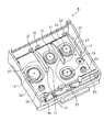
図2は、本実施例の液体収容装置2を表す概略斜視図である。また、図3は、本実施例
の液体収容装置2におけるインクカートリッジ5a及び5bの装着部6を表す概略斜視図
である。また、図4は、本実施例の液体収容装置2におけるインクカートリッジ5a及び
5bを表す概略斜視図である。また、図5及び図6は、本実施例の液体収容装置2を表す
分解斜視図である。
Next, the
FIG. 2 is a schematic perspective view showing the
図2、図5及び図6で表されるように、本実施例の液体収容装置2は、キャリッジ3、
インクカートリッジ5a及び5b、並びに、インクカートリッジ5a及び5bの装着部6
を備えている。
As shown in FIGS. 2, 5, and 6, the
It has.
ここで、インクカートリッジ5aはブラックインクを収容するインクカートリッジであ
り、インクカートリッジ5bはシアンインク、マゼンタインク及びイエローインクを収容
するインクカートリッジである。
そして、インクカートリッジ5aには固定部7aが設けられており、固定部7aが装着
部6に設けられた固定部8aに対して固定される。同様に、インクカートリッジ5bには
固定部7bが設けられており、固定部7bが装着部6に設けられた固定部8bに対して固
定される。
また、図4及び図6で表されるように、インクカートリッジ5a及び5bの底面側には
、インクを装着部6側に供給するためのインク供給口9が設けられている。
Here, the
The
4 and 6, an
また、図6で表されるように、装着部6の底面側には記録ヘッド4が設けられており、
図5及び図6で表されるように、キャリッジ3の底面部23における記録ヘッド4の位置
に対応する位置には孔部11が設けられている。
Further, as shown in FIG. 6, the
As shown in FIGS. 5 and 6, a
また、図3及び図5で表されるように、装着部6には、インクカートリッジ5a及び5
bのインク供給口9に対応する位置、即ち装着部6にインクカートリッジ5a及び5bを
装着した際にインク供給口9と対向する位置に、インク導入部10が設けられている。装
着部6にインクカートリッジ5a及び5bが装着されると、インク供給口9にインク導入
部10が嵌る。このような構成とすることでインクカートリッジ5a及び5bから装着部
6にインクを供給することが可能になっている。そして、記録ヘッド4は、インク導入部
10から導出されたインクを吐出し、被記録媒体Pに記録を行う。
なお、図3で表されるように、装着部6には、バネ32が設けられており、インクカー
トリッジ5a及び5bに対して、装着部6から離間させる方向に力を加えることが可能な
構成となっている。
As shown in FIGS. 3 and 5, the mounting
The
As shown in FIG. 3, the mounting
また、図5で表されるように、インクカートリッジ5aには第1接続部20aが設けら
れる基板22aが取り付けられており、インクカートリッジ5bには第1接続部20bが
設けられる基板22bが取り付けられている。
そして、図5及び図6で表されるように、装着部6には、第2接続部21aと第2接続
部21bとを有するコネクターユニット29と、基板13とが、取り付けられる。ここで
、第2接続部21aは第1接続部20aと電気的に接続可能な接続部であって、第2接続
部21bは第1接続部20bと接続可能な接続部である。なお、コネクターユニット29
に設けられたネジ穴16に、基板13に設けられたネジ穴14を介してネジ15を嵌める
ことにより、コネクター部29は基板13に取り付けられる。そして、コネクターユニッ
ト29が取り付けられた基板13にカバー12が嵌められる。
なお、コネクターユニット29の第2接続部21a及び21bが設けられた側とは反対
側には第3接続部36a及び36bが設けられており、第3接続部36a及び36bと基
板13に設けられた第4接続部37a及び37bとが接続するように、コネクターユニッ
ト29と基板13とは取り付けられる。
Further, as shown in FIG. 5, a
As shown in FIGS. 5 and 6, a
The
Note that
次に、装着部6に対するインクカートリッジ5a及び5bの位置を決める位置決め構成
と、装着部6に対する第2接続部21a及び21bの位置決め構成について説明する。
図7は本実施例の液体収容装置2を表す概略側面断面図であり、図8は図7とは異なる
位置における本実施例の液体収容装置2を表す概略側面断面図である。また、図9は、本
実施例の液体収容装置2を表す概略正面断面図である。また、図10は、図7及び図8と
は異なる位置における本実施例の液体収容装置2を表す概略側面断面図である。そして、
図11は、本実施例の液体収容装置2を表す概略背面断面図である。
Next, a positioning configuration that determines the positions of the
FIG. 7 is a schematic side sectional view showing the
FIG. 11 is a schematic rear sectional view showing the
図3、図5及び図7で表されるように、本実施例の液体収容装置2の装着部6は、該装
着部6に対するインクカートリッジ5a及び5bの方向Yの位置を決める第1位置決め部
としての規制部17を有している。規制部17は、図4、図6及び図7で表されるインク
カートリッジ5a及び5bの被規制部24と当接することにより、インクカートリッジ5
a及び5bの方向Yの移動を規制する。
As shown in FIGS. 3, 5, and 7, the mounting
The movement in the direction Y of a and 5b is restricted.
なお、インクカートリッジ5a及び5bは、第1接続部20a及び20bと第2接続部
21a及び21bとを接続した際の反力により、規制部17に向けて方向Yへ付勢するよ
うに構成されている。このため、方向Yへ付勢する付勢部を別途構成する必要が無いため
、装着部6を低コストで作製している。
The
また、図3、図5、図6及び図8で表されるように、本実施例の液体収容装置2の装着
部6は、該装着部6に対するインクカートリッジ5a及び5bの方向Zの位置を決める第
1位置決め部としての規制部18及び19を有している。規制部18は、図6及び図8で
表されるインクカートリッジ5a及び5bの被規制部25と当接することにより、インク
カートリッジ5a及び5bの方向Zの移動を規制する。そして、規制部19は、図4、図
5及び図8で表されるインクカートリッジ5a及び5bの被規制部26と当接することに
より、インクカートリッジ5a及び5bの方向Zの移動を規制する。
As shown in FIGS. 3, 5, 6, and 8, the mounting
なお、インクカートリッジ5a及び5bは、図3で表される付勢部としてのバネ32に
より方向Zに力が加えられ、バネ32の付勢力により、規制部18及び19に被規制部2
5及び26が付勢される。このような構成により、方向Zへ付勢する付勢部をバネ32に
より簡単に構成し、第1位置決め部をバネ32と規制部18及び19とにより簡単に構成
している。
特に、本実施例のように、第1接続部20a及び20bと第2接続部21a及び21b
とを接続した際の反力により規制部17に向けて方向Yへ付勢するように構成され、バネ
32により方向Zへ付勢するように構成されていると、低コストで高い精度で位置決めで
きるため特に好ましい。
The
5 and 26 are activated. With such a configuration, the urging portion for urging in the direction Z is simply configured by the
In particular, as in this embodiment, the
Is configured to be urged in the direction Y toward the restricting
また、図3、図5及び図9で表されるように、本実施例の液体収容装置2の装着部3は
、該装着部3に対するインクカートリッジ5a及び5bの方向Xの位置を決める第1位置
決め部としての規制部27を有している。規制部27は、図4、図6及び図9で表される
インクカートリッジ5a及び5bの被規制部28と当接することにより、インクカートリ
ッジ5a及び5bの方向Xの移動を規制する。
As shown in FIGS. 3, 5, and 9, the mounting
このように、本実施例の液体収容装置2及び記録装置1は、第1接続部20a及び20
bを有し、インクを収容するインクカートリッジ5a及び5bと、第1接続部20a及び
20bと接続可能な第2接続部21a及び21bとインク導入部10とを有する装着部6
と、装着部6が取り付けられて方向Bに移動するキャリッジ3と、を備えている。
このため、装着部と被装着部とに接続部が設けられる構成となり、第2接続部21a及
び21bが装着部6以外に設けられる構成、例えば、第2接続部21a及び21bがキャ
リッジ3に設けられる構成等よりも、第1接続部20a及び20bと第2接続部21a及
び21bとの間の接点不良等を抑制することができる。すなわち、インクカートリッジ5
a及び5bを装着部6に装着した際の不具合を抑制している。
As described above, the
b, an
And a
For this reason, it becomes the structure by which a connection part is provided in a mounting part and a to-be-attached part, and the
The trouble at the time of mounting a and 5b on mounting
そして、装着部6は、該装着部6に対するインクカートリッジ5a及び5bの位置を決
める第1位置決め部を有している。なお、本実施例の液体収容装置2の第1位置決め部は
、方向X、方向Y及び方向Zの3方向、即ち3次元方向に位置決めしている。このような
構成により、インクカートリッジ5a及び5bを装着部6に対して適切な位置に固定でき
ることで、第1接続部20a及び20bと第2接続部21a及び21bとの間の接点不良
等を抑制している。すなわち、効果的にインクカートリッジ5a及び5bを装着部6に装
着した際の不具合を抑制している。
The mounting
なお、図2、図3、図5及び図6で表されるように、本実施例の液体収容装置2の装着
部6は、箱型であり、インクカートリッジ5a及び5bを囲う壁部33が設けられている
。このため、装着部6は、壁部6によりインクカートリッジ5a及び5bをより確りと位
置決め可能にし、効果的にインクカートリッジ5a及び5bを装着部6に装着した際の不
具合を抑制している。
2, 3, 5, and 6, the mounting
また、図10で表されるように、本実施例の液体収容装置2の装着部6は、該装着部6
に対する第2接続部21a及び21bの方向Y及び方向Zの位置を決める第2位置決め部
としての規制部30及び31を有している。規制部30及び31は、図10で表されるよ
うに、基板13の異なる2面と当接することにより、第2接続部21a及び21b(コネ
クターユニット29)の方向Y及び方向Zの移動を規制している。
なお、コネクターユニット29はネジ15により基板13と固定されており、カバー1
2によるコネクターユニット29への付勢力と、第2接続部21a及び21bに対する第
1接続部20a及び20bからの接続に伴う反力とにより、基板13は規制部30及び3
1に付勢される。ただし、このような構成に限定されず、コネクターユニット29を装着
部6に直接固定してもよい。
Further, as shown in FIG. 10, the mounting
There are restricting
The
2 and the reaction force accompanying the connection from the
Energized to 1. However, the present invention is not limited to such a configuration, and the
また、図11で表されるように、本実施例の液体収容装置2の装着部6は、該装着部6
に対する第2接続部21a及び21bの方向Xの位置を決める第2位置決め部としての規
制部34を有している。規制部34は、図11で表されるように、装着部6の被規制部3
5と当接することにより、第2接続部21a及び21b(コネクターユニット29)の方
向Xの移動を規制している。
In addition, as shown in FIG. 11, the mounting
There is a restricting
5, the movement of the second connecting
このように、本実施例の液体収容装置2の装着部6は、該装着部6に対する第2接続部
21a及び21bの位置を決める第2位置決め部を有している。このため、装着部6に対
して第2接続部21a及び21bを適切な位置に固定し、第1接続部20a及び20bと
第2接続部21a及び21bとの間の接点不良等を効果的に抑制している。すなわち、イ
ンクカートリッジ5a及び5bを装着部6に装着した際の不具合を効果的に抑制している
。
特に、方向X、方向Y及び方向Zの3方向、即ち3次元方向に位置決めしているため、
前記第2位置決め部において、より確りと位置決め可能になり、効果的にインクカートリ
ッジ5a及び5bを装着部6に装着した際の不具合を抑制している。
As described above, the mounting
In particular, since positioning is performed in the three directions of direction X, direction Y and direction Z, that is, the three-dimensional direction,
In the second positioning portion, positioning can be performed with more certainty, and problems when the
1 記録装置、2 液体収容装置、3 キャリッジ、4 記録ヘッド、
5a、5b インクカートリッジ(収容体)、6 装着部、7a、7b 固定部、
8a、8b 固定部、9 インク供給口、10 インク導入部(導入部)、11 孔部
、
12 カバー、13 基板、14 ネジ穴、15 ネジ、16 ネジ穴、
17 規制部(第1位置決め部)、18 規制部(第1位置決め部)、
19 規制部(第1位置決め部)、20a、20b 第1接続部、
21a、21b 第2接続部、22a、22b 基板、23 キャリッジ3の底面部、
24 被規制部、25 被規制部、26 被規制部、
27 規制部(第1位置決め部)、28 被規制部、29 コネクターユニット、
30 規制部(第2位置決め部)、31 規制部(第2位置決め部)、
32 バネ(付勢部)、33 壁部、34 規制部(第2位置決め部)、
35 被規制部、36a、36b 第3接続部、37a、37b 第4接続部、
P 被記録媒体
1 recording device, 2 liquid storage device, 3 carriage, 4 recording head,
5a, 5b Ink cartridge (container), 6 mounting portion, 7a, 7b fixing portion,
8a, 8b fixing part, 9 ink supply port, 10 ink introduction part (introduction part), 11 hole part,
12 Cover, 13 Substrate, 14 Screw hole, 15 Screw, 16 Screw hole,
17 restriction part (first positioning part), 18 restriction part (first positioning part),
19 regulation part (1st positioning part), 20a, 20b 1st connection part,
21a, 21b second connection portion, 22a, 22b substrate, 23 bottom surface portion of
24 regulated parts, 25 regulated parts, 26 regulated parts,
27 restricting part (first positioning part), 28 restricted part, 29 connector unit,
30 restriction part (second positioning part), 31 restriction part (second positioning part),
32 spring (biasing part), 33 wall part, 34 regulating part (second positioning part),
35 regulated portion, 36a, 36b third connection portion, 37a, 37b fourth connection portion,
P Recording medium
Claims (4)
前記第1接続部と電気的に接続可能な第2接続部と、前記収容体からの前記液体を導入する導入部と、前記導入部から導出された前記液体を吐出し、被記録媒体に記録を行う記録ヘッドと、を有する装着部と、
前記装着部が取り付けられるキャリッジと、を備え、
前記装着部は、該装着部に対する前記収容体の位置を決める第1位置決め部を有し、
前記第1位置決め部は、前記収容体の移動を規制する規制部と前記装着部内底部に設けられ、前記収容体を前記規制部により鉛直方向に付勢する付勢部と、を有す
ることを特徴とする記録装置。 Having a first connecting portion and mounting a container for containing a liquid;
A second connecting portion that can be electrically connected to the first connecting portion; an introducing portion that introduces the liquid from the container; and the liquid led out from the introducing portion is ejected and recorded on a recording medium. A recording head, and a mounting unit having
A carriage to which the mounting portion is attached,
The mounting portion has a first positioning portion that determines the position of the container relative to the mounting portion;
The first positioning portion includes a restricting portion that restricts movement of the container and an urging portion that is provided on the inner bottom portion of the mounting portion and urges the container in the vertical direction by the restricting portion. /> A recording apparatus.
前記装着部は、前記収容体を囲う壁部が設けられていることを特徴とする記録装置。 The recording apparatus according to claim 1,
The recording apparatus according to claim 1, wherein the mounting portion is provided with a wall portion surrounding the container .
前記装着部は、前記収容体の移動を規制する規制部を有し、
前記第1接続部と前記第2接続部とを接続した際の反力により前記収容体を前記規制部
に向けて付勢するように構成されていることを特徴とする記録装置。 The recording apparatus according to claim 1 or 2,
The mounting portion has a restricting portion that restricts movement of the container.
The restricting portion is moved by the reaction force when the first connecting portion and the second connecting portion are connected.
A recording apparatus characterized by being biased toward the head .
前記装着部は、該装着部に対する前記第2接続部の位置を決める第2位置決め部を有す
ることを特徴とする記録装置。 The recording apparatus according to any one of claims 1 to 3 ,
The mounting portion has a second positioning portion that determines a position of the second connection portion with respect to the mounting portion.
Recording apparatus characterized by that.
Priority Applications (62)
| Application Number | Priority Date | Filing Date | Title |
|---|---|---|---|
| JP2013260964A JP6287160B2 (en) | 2013-12-18 | 2013-12-18 | Recording device |
| CA2932434A CA2932434C (en) | 2013-12-18 | 2014-12-09 | Liquid supply unit |
| PCT/JP2014/006136 WO2015093008A1 (en) | 2013-12-18 | 2014-12-09 | Liquid supply unit |
| RU2016123602A RU2660070C1 (en) | 2013-12-18 | 2014-12-09 | Liquid supply unit |
| AU2014368304A AU2014368304B2 (en) | 2013-12-18 | 2014-12-09 | Liquid supply unit |
| PCT/JP2014/006167 WO2015093012A1 (en) | 2013-12-18 | 2014-12-10 | Liquid supply unit |
| CN201410773179.4A CN104723684B (en) | 2013-12-18 | 2014-12-12 | Fluid supply unit |
| CN201410770713.6A CN104723683B (en) | 2013-12-18 | 2014-12-12 | Fluid supply unit |
| PCT/JP2014/006218 WO2015093024A1 (en) | 2013-12-18 | 2014-12-12 | Liquid supply unit |
| AU2014368232A AU2014368232B2 (en) | 2013-12-18 | 2014-12-12 | Liquid supply unit |
| RU2016123600A RU2645206C2 (en) | 2013-12-18 | 2014-12-12 | Fluid feed unit |
| PCT/JP2014/006187 WO2015093016A1 (en) | 2013-12-18 | 2014-12-12 | Liquid supply unit |
| CN201420790410.6U CN204506139U (en) | 2013-12-18 | 2014-12-12 | Fluid supply unit |
| CN201420788209.4U CN204472115U (en) | 2013-12-18 | 2014-12-12 | Fluid supply unit |
| CN201710971238.2A CN107672316A (en) | 2013-12-18 | 2014-12-12 | Fluid supply unit |
| PCT/JP2014/006221 WO2015093027A1 (en) | 2013-12-18 | 2014-12-12 | Liquid supply unit-mounting mechanism and liquid supply unit |
| CA2932696A CA2932696C (en) | 2013-12-18 | 2014-12-12 | Liquid supply unit |
| PCT/JP2014/006222 WO2015093028A1 (en) | 2013-12-18 | 2014-12-12 | Liquid supply unit |
| BR112016014143-1A BR112016014143A2 (en) | 2013-12-18 | 2014-12-12 | LIQUID SUPPLY UNIT |
| CN201710561409.4A CN107297957B (en) | 2013-12-18 | 2014-12-12 | Fluid supply unit |
| CN201410776917.0A CN104723685B (en) | 2013-12-18 | 2014-12-15 | Fluid supply unit |
| CN201711306297.4A CN107891670B (en) | 2013-12-18 | 2014-12-15 | Fluid supply unit |
| CN201420797072.9U CN204566928U (en) | 2013-12-18 | 2014-12-15 | Fluid supply unit |
| CN201420795684.4U CN204605190U (en) | 2013-12-18 | 2014-12-15 | Fluid supply unit |
| CN201410778150.5A CN104723686B (en) | 2013-12-18 | 2014-12-15 | Fluid supply unit |
| ES14198200.9T ES2691520T3 (en) | 2013-12-18 | 2014-12-16 | Liquid supply unit |
| EP14198199.3A EP2886349B1 (en) | 2013-12-18 | 2014-12-16 | Liquid supply unit |
| EP14198197.7A EP2886347B1 (en) | 2013-12-18 | 2014-12-16 | Liquid supply unit |
| CN201710876901.0A CN107521235B (en) | 2013-12-18 | 2014-12-16 | Liquid supply unit |
| EP14198200.9A EP2886350B1 (en) | 2013-12-18 | 2014-12-16 | Liquid supply unit |
| ES14198198T ES2746323T3 (en) | 2013-12-18 | 2014-12-16 | Liquid supply unit |
| EP14198198.5A EP2886348B8 (en) | 2013-12-18 | 2014-12-16 | Liquid supply unit |
| ES14198202T ES2733105T3 (en) | 2013-12-18 | 2014-12-16 | Liquid supply unit |
| EP14198195.1A EP2886346B1 (en) | 2013-12-18 | 2014-12-16 | Liquid supply unit mounting mechanism and liquid supply unit |
| EP14198202.5A EP2886351B1 (en) | 2013-12-18 | 2014-12-16 | Liquid supply unit |
| EP19176167.5A EP3549773A1 (en) | 2013-12-18 | 2014-12-16 | Liquid supply unit |
| PL14198199T PL2886349T3 (en) | 2013-12-18 | 2014-12-16 | Liquid supply unit |
| ES14198197T ES2704093T3 (en) | 2013-12-18 | 2014-12-16 | Liquid supply unit |
| CN201410779761.1A CN104723687B (en) | 2013-12-18 | 2014-12-16 | Fluid supply unit |
| CN201420797761.XU CN204605191U (en) | 2013-12-18 | 2014-12-16 | Fluid supply unit |
| ES14198199T ES2740074T3 (en) | 2013-12-18 | 2014-12-16 | Liquid supply unit |
| TW103144167A TW201536577A (en) | 2013-12-18 | 2014-12-17 | Liquid supply unit mounting mechanism and liquid supply unit |
| US14/573,053 US9266340B2 (en) | 2013-12-18 | 2014-12-17 | Liquid supply unit |
| US14/573,424 US9844945B2 (en) | 2013-12-18 | 2014-12-17 | Liquid supply unit |
| TW103144176A TWI643762B (en) | 2013-12-18 | 2014-12-17 | Liquid supply unit |
| TW103144165A TWI636892B (en) | 2013-12-18 | 2014-12-17 | Liquid supply unit |
| CN201420802342.0U CN204605192U (en) | 2013-12-18 | 2014-12-17 | Fluid supply unit installing mechanism and fluid supply unit |
| TW103144169A TWI638723B (en) | 2013-12-18 | 2014-12-17 | Liquid supply unit |
| CN201410784691.9A CN104723688B (en) | 2013-12-18 | 2014-12-17 | Fluid supply unit installing mechanism and fluid supply unit |
| US14/573,275 US9321272B2 (en) | 2013-12-18 | 2014-12-17 | Liquid supply unit mounting mechanism and liquid supply unit |
| US14/573,192 US9511594B2 (en) | 2013-12-18 | 2014-12-17 | Liquid supply unit |
| US14/573,128 US9233546B2 (en) | 2013-12-18 | 2014-12-17 | Liquid supply unit |
| TW103144164A TW201536574A (en) | 2013-12-18 | 2014-12-17 | Liquid supply unit |
| TW103144166A TWI647121B (en) | 2013-12-18 | 2014-12-17 | Liquid supply unit |
| US14/573,516 US9233547B2 (en) | 2013-12-18 | 2014-12-17 | Liquid supply unit |
| US14/878,529 US9346277B2 (en) | 2013-12-18 | 2015-10-08 | Liquid supply unit |
| US14/964,929 US9682565B2 (en) | 2013-12-18 | 2015-12-10 | Liquid supply unit |
| US14/964,976 US9682566B2 (en) | 2013-12-18 | 2015-12-10 | Liquid supply unit |
| US15/134,230 US9579900B2 (en) | 2013-12-18 | 2016-04-20 | Liquid supply unit |
| US15/147,101 US9694588B2 (en) | 2013-12-18 | 2016-05-05 | Liquid supply unit |
| US15/430,987 US10220627B2 (en) | 2013-12-18 | 2017-02-13 | Liquid supply unit and engaged part |
| US15/717,654 US10220628B2 (en) | 2013-12-18 | 2017-09-27 | Liquid supply unit |
Applications Claiming Priority (1)
| Application Number | Priority Date | Filing Date | Title |
|---|---|---|---|
| JP2013260964A JP6287160B2 (en) | 2013-12-18 | 2013-12-18 | Recording device |
Publications (3)
| Publication Number | Publication Date |
|---|---|
| JP2015116721A JP2015116721A (en) | 2015-06-25 |
| JP2015116721A5 JP2015116721A5 (en) | 2017-01-19 |
| JP6287160B2 true JP6287160B2 (en) | 2018-03-07 |
Family
ID=53529919
Family Applications (1)
| Application Number | Title | Priority Date | Filing Date |
|---|---|---|---|
| JP2013260964A Active JP6287160B2 (en) | 2013-12-18 | 2013-12-18 | Recording device |
Country Status (1)
| Country | Link |
|---|---|
| JP (1) | JP6287160B2 (en) |
Families Citing this family (2)
| Publication number | Priority date | Publication date | Assignee | Title |
|---|---|---|---|---|
| JP7363420B2 (en) * | 2019-11-29 | 2023-10-18 | セイコーエプソン株式会社 | Cartridges and printing devices |
| CN112090998B (en) * | 2020-09-07 | 2022-10-25 | 佛山市新濠泰铝材有限公司 | Finishing processing assembly line after rolling forming of aluminum alloy section |
Family Cites Families (2)
| Publication number | Priority date | Publication date | Assignee | Title |
|---|---|---|---|---|
| JP2010023458A (en) * | 2008-07-24 | 2010-02-04 | Canon Inc | Ink tank and inkjet recording system |
| US8615054B2 (en) * | 2010-09-24 | 2013-12-24 | Intel Corporation | Close-loop power amplifier pre-distortion correction |
-
2013
- 2013-12-18 JP JP2013260964A patent/JP6287160B2/en active Active
Also Published As
| Publication number | Publication date |
|---|---|
| JP2015116721A (en) | 2015-06-25 |
Similar Documents
| Publication | Publication Date | Title |
|---|---|---|
| US9855757B2 (en) | Liquid cartridge provided with cartridge body and storage element fixed thereto by adhesive agent and method for manufacturing the same | |
| WO2015093027A1 (en) | Liquid supply unit-mounting mechanism and liquid supply unit | |
| JP5942450B2 (en) | Mounting member, liquid container including mounting member, and liquid supply system | |
| JP2007144905A (en) | Liquid supply device, ink supply device and ink jet recorder | |
| US10081207B2 (en) | Recording apparatus | |
| JP6287160B2 (en) | Recording device | |
| JP6528564B2 (en) | Liquid supply unit | |
| US20120195158A1 (en) | Liquid storage container mounted on liquid ejecting apparatus | |
| US20180093487A1 (en) | Cartridge accommodating apparatus and system provided with the same | |
| JP2013056502A (en) | Inkjet recording apparatus | |
| JP2016107620A (en) | Liquid supply unit and liquid supply system | |
| JP6056181B2 (en) | Recording device | |
| EP3711955B1 (en) | Liquid ejecting unit and liquid ejecting apparatus | |
| WO2020045218A1 (en) | Protective member for head housings and system provided with same | |
| JP2018015984A (en) | Recording device | |
| WO2023047781A1 (en) | Inkjet head | |
| WO2023047779A1 (en) | Inkjet head | |
| WO2023047780A1 (en) | Inkjet head | |
| JP6379560B2 (en) | Image forming apparatus | |
| JP7471941B2 (en) | LIQUID EJECTION HEAD AND LIQUID EJECTION APPARATUS | |
| WO2023047778A1 (en) | Inkjet head | |
| JP6866844B2 (en) | system | |
| JP5609178B2 (en) | Liquid ejector | |
| JP7259340B2 (en) | system | |
| JP6291928B2 (en) | Recording device |
Legal Events
| Date | Code | Title | Description |
|---|---|---|---|
| RD04 | Notification of resignation of power of attorney |
Free format text: JAPANESE INTERMEDIATE CODE: A7424 Effective date: 20160617 |
|
| RD03 | Notification of appointment of power of attorney |
Free format text: JAPANESE INTERMEDIATE CODE: A7423 Effective date: 20160627 |
|
| A521 | Written amendment |
Free format text: JAPANESE INTERMEDIATE CODE: A523 Effective date: 20161130 |
|
| A621 | Written request for application examination |
Free format text: JAPANESE INTERMEDIATE CODE: A621 Effective date: 20161130 |
|
| A131 | Notification of reasons for refusal |
Free format text: JAPANESE INTERMEDIATE CODE: A131 Effective date: 20170912 |
|
| A521 | Written amendment |
Free format text: JAPANESE INTERMEDIATE CODE: A523 Effective date: 20171102 |
|
| TRDD | Decision of grant or rejection written | ||
| A01 | Written decision to grant a patent or to grant a registration (utility model) |
Free format text: JAPANESE INTERMEDIATE CODE: A01 Effective date: 20180109 |
|
| A61 | First payment of annual fees (during grant procedure) |
Free format text: JAPANESE INTERMEDIATE CODE: A61 Effective date: 20180122 |
|
| R150 | Certificate of patent or registration of utility model |
Ref document number: 6287160 Country of ref document: JP Free format text: JAPANESE INTERMEDIATE CODE: R150 |