JP6286364B2 - Hermetic compressor and refrigeration system - Google Patents
Hermetic compressor and refrigeration system Download PDFInfo
- Publication number
- JP6286364B2 JP6286364B2 JP2014551898A JP2014551898A JP6286364B2 JP 6286364 B2 JP6286364 B2 JP 6286364B2 JP 2014551898 A JP2014551898 A JP 2014551898A JP 2014551898 A JP2014551898 A JP 2014551898A JP 6286364 B2 JP6286364 B2 JP 6286364B2
- Authority
- JP
- Japan
- Prior art keywords
- suction
- communication pipe
- suction hole
- cylinder
- side opening
- Prior art date
- Legal status (The legal status is an assumption and is not a legal conclusion. Google has not performed a legal analysis and makes no representation as to the accuracy of the status listed.)
- Active
Links
- 238000005057 refrigeration Methods 0.000 title claims description 28
- 238000004891 communication Methods 0.000 claims description 131
- 239000003507 refrigerant Substances 0.000 claims description 79
- 230000006835 compression Effects 0.000 claims description 32
- 238000007906 compression Methods 0.000 claims description 32
- 230000002093 peripheral effect Effects 0.000 claims description 27
- 230000007423 decrease Effects 0.000 claims description 8
- 239000010687 lubricating oil Substances 0.000 claims description 8
- 238000004519 manufacturing process Methods 0.000 description 11
- 230000000052 comparative effect Effects 0.000 description 5
- 230000007704 transition Effects 0.000 description 5
- 238000005452 bending Methods 0.000 description 4
- 239000002184 metal Substances 0.000 description 4
- 230000006837 decompression Effects 0.000 description 3
- 239000003921 oil Substances 0.000 description 3
- 230000008859 change Effects 0.000 description 2
- 238000001816 cooling Methods 0.000 description 2
- 238000012986 modification Methods 0.000 description 2
- 230000004048 modification Effects 0.000 description 2
- 238000000465 moulding Methods 0.000 description 2
- 229920001707 polybutylene terephthalate Polymers 0.000 description 2
- 230000009471 action Effects 0.000 description 1
- 230000004075 alteration Effects 0.000 description 1
- 230000015572 biosynthetic process Effects 0.000 description 1
- 238000009833 condensation Methods 0.000 description 1
- 230000005494 condensation Effects 0.000 description 1
- 238000010586 diagram Methods 0.000 description 1
- 230000000694 effects Effects 0.000 description 1
- 230000008020 evaporation Effects 0.000 description 1
- 238000001704 evaporation Methods 0.000 description 1
- 238000007710 freezing Methods 0.000 description 1
- 230000008014 freezing Effects 0.000 description 1
- 230000030279 gene silencing Effects 0.000 description 1
- 239000011810 insulating material Substances 0.000 description 1
- 238000009413 insulation Methods 0.000 description 1
- 238000011835 investigation Methods 0.000 description 1
- 239000000203 mixture Substances 0.000 description 1
- -1 polybutylene terephthalate Polymers 0.000 description 1
- 239000000843 powder Substances 0.000 description 1
- 238000004663 powder metallurgy Methods 0.000 description 1
- 239000011347 resin Substances 0.000 description 1
- 229920005989 resin Polymers 0.000 description 1
- 238000007789 sealing Methods 0.000 description 1
- 238000005245 sintering Methods 0.000 description 1
- XLYOFNOQVPJJNP-UHFFFAOYSA-N water Substances O XLYOFNOQVPJJNP-UHFFFAOYSA-N 0.000 description 1
Images


Classifications
-
- F—MECHANICAL ENGINEERING; LIGHTING; HEATING; WEAPONS; BLASTING
- F04—POSITIVE - DISPLACEMENT MACHINES FOR LIQUIDS; PUMPS FOR LIQUIDS OR ELASTIC FLUIDS
- F04B—POSITIVE-DISPLACEMENT MACHINES FOR LIQUIDS; PUMPS
- F04B39/00—Component parts, details, or accessories, of pumps or pumping systems specially adapted for elastic fluids, not otherwise provided for in, or of interest apart from, groups F04B25/00 - F04B37/00
- F04B39/10—Adaptations or arrangements of distribution members
- F04B39/1066—Valve plates
-
- F—MECHANICAL ENGINEERING; LIGHTING; HEATING; WEAPONS; BLASTING
- F04—POSITIVE - DISPLACEMENT MACHINES FOR LIQUIDS; PUMPS FOR LIQUIDS OR ELASTIC FLUIDS
- F04B—POSITIVE-DISPLACEMENT MACHINES FOR LIQUIDS; PUMPS
- F04B39/00—Component parts, details, or accessories, of pumps or pumping systems specially adapted for elastic fluids, not otherwise provided for in, or of interest apart from, groups F04B25/00 - F04B37/00
- F04B39/10—Adaptations or arrangements of distribution members
-
- F—MECHANICAL ENGINEERING; LIGHTING; HEATING; WEAPONS; BLASTING
- F04—POSITIVE - DISPLACEMENT MACHINES FOR LIQUIDS; PUMPS FOR LIQUIDS OR ELASTIC FLUIDS
- F04B—POSITIVE-DISPLACEMENT MACHINES FOR LIQUIDS; PUMPS
- F04B39/00—Component parts, details, or accessories, of pumps or pumping systems specially adapted for elastic fluids, not otherwise provided for in, or of interest apart from, groups F04B25/00 - F04B37/00
- F04B39/0027—Pulsation and noise damping means
- F04B39/0055—Pulsation and noise damping means with a special shape of fluid passage, e.g. bends, throttles, diameter changes, pipes
- F04B39/0061—Pulsation and noise damping means with a special shape of fluid passage, e.g. bends, throttles, diameter changes, pipes using muffler volumes
-
- F—MECHANICAL ENGINEERING; LIGHTING; HEATING; WEAPONS; BLASTING
- F04—POSITIVE - DISPLACEMENT MACHINES FOR LIQUIDS; PUMPS FOR LIQUIDS OR ELASTIC FLUIDS
- F04B—POSITIVE-DISPLACEMENT MACHINES FOR LIQUIDS; PUMPS
- F04B39/00—Component parts, details, or accessories, of pumps or pumping systems specially adapted for elastic fluids, not otherwise provided for in, or of interest apart from, groups F04B25/00 - F04B37/00
- F04B39/02—Lubrication
- F04B39/0223—Lubrication characterised by the compressor type
- F04B39/023—Hermetic compressors
-
- F—MECHANICAL ENGINEERING; LIGHTING; HEATING; WEAPONS; BLASTING
- F04—POSITIVE - DISPLACEMENT MACHINES FOR LIQUIDS; PUMPS FOR LIQUIDS OR ELASTIC FLUIDS
- F04B—POSITIVE-DISPLACEMENT MACHINES FOR LIQUIDS; PUMPS
- F04B39/00—Component parts, details, or accessories, of pumps or pumping systems specially adapted for elastic fluids, not otherwise provided for in, or of interest apart from, groups F04B25/00 - F04B37/00
- F04B39/06—Cooling; Heating; Prevention of freezing
-
- F—MECHANICAL ENGINEERING; LIGHTING; HEATING; WEAPONS; BLASTING
- F25—REFRIGERATION OR COOLING; COMBINED HEATING AND REFRIGERATION SYSTEMS; HEAT PUMP SYSTEMS; MANUFACTURE OR STORAGE OF ICE; LIQUEFACTION SOLIDIFICATION OF GASES
- F25B—REFRIGERATION MACHINES, PLANTS OR SYSTEMS; COMBINED HEATING AND REFRIGERATION SYSTEMS; HEAT PUMP SYSTEMS
- F25B31/00—Compressor arrangements
-
- F—MECHANICAL ENGINEERING; LIGHTING; HEATING; WEAPONS; BLASTING
- F25—REFRIGERATION OR COOLING; COMBINED HEATING AND REFRIGERATION SYSTEMS; HEAT PUMP SYSTEMS; MANUFACTURE OR STORAGE OF ICE; LIQUEFACTION SOLIDIFICATION OF GASES
- F25B—REFRIGERATION MACHINES, PLANTS OR SYSTEMS; COMBINED HEATING AND REFRIGERATION SYSTEMS; HEAT PUMP SYSTEMS
- F25B2500/00—Problems to be solved
- F25B2500/12—Sound
Description
本発明は、冷凍装置またはエアーコンディショナー等の冷凍サイクルに用いられる密閉型圧縮機、並びに、これを用いた冷凍装置に関するものである。 The present invention relates to a hermetic compressor used in a refrigeration cycle such as a refrigeration apparatus or an air conditioner, and a refrigeration apparatus using the same.
密閉型圧縮機は、冷凍冷蔵庫等の冷凍装置、あるいは、エアーコンディショナー等に広く用いられているが、このような密閉型圧縮機においては、近年、消費電力を低減させるために、高効率化、並びに高信頼性化が望まれている。 The hermetic compressor is widely used in a refrigeration apparatus such as a refrigerator-freezer or an air conditioner. However, in such a hermetic compressor, in recent years, in order to reduce power consumption, the efficiency has been increased. In addition, high reliability is desired.
例えば、特許文献1には、密閉型圧縮機の高効率化および高信頼性化を目的として、バルブプレートに設けられる吸入孔の一部を湾曲化させる構成が開示されている。バルブプレートは、シリンダの端部を閉止するように設けられ、吸入孔および吐出孔が形成されている。吸入孔には、サクションマフラーの連通管がつながっており、連通管から吸入孔を介して冷媒ガスがシリンダ内に吸入される。 For example, Patent Document 1 discloses a configuration in which a part of a suction hole provided in a valve plate is curved for the purpose of improving the efficiency and reliability of a hermetic compressor. The valve plate is provided so as to close the end of the cylinder, and has a suction hole and a discharge hole. A communication pipe of a suction muffler is connected to the suction hole, and refrigerant gas is sucked into the cylinder from the communication pipe through the suction hole.
サクションマフラーは、シリンダの下方に位置しており、連通管は、下方のサクションマフラーから上方に延伸している。連通管の延伸方向を縦方向とすれば、シリンダは横方向に設けられている。シリンダの端部にはバルブプレートが位置しており、連通管の上端には、横方向に連通管出口部が設けられている。この連通管出口部がバルブプレートの吸入孔に連結されることで、これらにより吸入流路が形成される。したがって、連通管から吸入流路(連通管出口部および吸入孔)に至るまでの冷媒ガスの流路は、縦方向から連通管の上端で横方向にカーブするような経路となる。 The suction muffler is located below the cylinder, and the communication pipe extends upward from the lower suction muffler. If the extending direction of the communication pipe is the vertical direction, the cylinder is provided in the horizontal direction. A valve plate is located at the end of the cylinder, and a communication pipe outlet is provided in the lateral direction at the upper end of the communication pipe. The communication pipe outlet is connected to the suction hole of the valve plate, thereby forming a suction flow path. Therefore, the refrigerant gas flow path from the communication pipe to the suction flow path (communication pipe outlet and suction hole) is a path that curves in the horizontal direction from the vertical direction at the upper end of the communication pipe.
図11に示すように、特許文献1に開示されるバルブプレート80では、吸入孔83は、略U字形状に形成されており、さらに、シリンダ側の開口と連通管側の開口との間に、湾曲した移行部(transition portion)Tが形成されている。この移行部Tは、吸入流路831の内側側面(internal profile)を少なくとも部分的に湾曲させることにより、ダクト部(duct portion)を確定させている。このような吸入流路831によれば、冷媒ガスが連通管出口部863から吸入孔83に円滑に移行しやすくなり、冷媒ガスの吸入抵抗が抑制可能となる。吸入抵抗を抑制することで単位時間当たりの冷媒ガスの吸入質量(冷媒循環量)が大きくなれば、密閉型圧縮機の効率が向上することになる。
As shown in FIG. 11, in the
しかしながら、前述した特許文献1に開示される密閉型圧縮機では、バルブプレート80の製造が容易ではなく、また、本発明者らによる検討の結果、前記構成のバルブプレート80であっても、吸入孔83近傍において吸入抵抗の増加を有効に抑制できない、という課題が明らかとなった。
However, in the hermetic compressor disclosed in Patent Document 1 described above, it is not easy to manufacture the
バルブプレートは、一般に、金属粉末を金型で成型して焼結すること(粉末冶金)により製造される。前記構成のバルブプレート80は、吸入孔83が略U字形状という複雑な形状であることから、金型の製作時に、当該金型の造形が複雑化してしまう。そのため、金型を容易に製造することができず、結果としてバルブプレート80も容易に製造できなくなる。
The valve plate is generally manufactured by molding metal powder with a mold and sintering (powder metallurgy). In the
また、連通管は、一般に、略円形状の断面を有しているが、前記構成のバルブプレート80では、吸入孔83が略U字形状である。そのため、図11に示すように、吸入流路831においては、移行部Tが形成されるとしても、流路の断面形状が略円形状(連通管出口部863)から略U字形状(吸入孔83)に急激に変化することになる。これにより、冷媒ガスは、広い断面積の流路(連通管出口部863)から、狭い断面積の流路(吸入孔83)に急激に流入することになるので、冷媒ガスの吸入抵抗を増加させる。
In addition, the communication pipe generally has a substantially circular cross section, but in the
さらに、通常、吸入孔付近では冷媒ガスの流れが速くなるが、吸入孔83が略U字形状であると、当該吸入孔83の中央部と両側部とでは、冷媒ガスの流速に違いが生じやすくなる。これにより、略U字形状の吸入孔83においては、中央部の流れと両側部の流れという2種類の流れが生じてしまい、結果として冷媒ガスがシリンダ内に円滑に流入できなくなる。
Further, normally, the flow of the refrigerant gas becomes faster near the suction hole. However, if the
このように、前記構成のバルブプレート80を用いた場合、流路面積の急激な変化、並びに、2種類の流れの形成により、吸入孔83近傍において吸入抵抗が増加する。そのため、このようなバルブプレート80を備える密閉型圧縮機においては、吸入損失が大きくなり、圧縮効率が低下してしまう。
Thus, when the
本発明はこのような課題を解決するためになされたものであって、バルブプレートの製作を容易にするとともに、より一層効率の高い密閉型圧縮機を提供することを目的とする。 The present invention has been made to solve such a problem, and an object of the present invention is to provide a hermetic compressor that facilitates the manufacture of a valve plate and is more efficient.
本発明に係る密閉型圧縮機は、前記の課題を解決するために、潤滑油が貯留される密閉容器と、当該密閉容器内に収容される電動要素と、前記密閉容器内に収容され、前記電動要素により駆動され冷媒を圧縮する圧縮要素と、を備え、前記圧縮要素は、圧縮室を形成するシリンダと、前記シリンダの一方の端部を封止するとともに、吸入孔および吐出孔が形成されたバルブプレートと、前記吸入孔を開閉する吸入リードと、前記シリンダよりも下方に位置し、内部に消音空間を有し、前記吸入孔に連結される連通管を備えるサクションマフラーと、を備え、前記連通管は、前記サクションマフラーから前記シリンダの端部に向かって上方に延伸し、その上端に、前記吸入孔に連通する連通管出口部が設けられ、前記連通管出口部は、上部形状が曲線状に突出した突出形状であり、かつ、下部形状が矩形状である連通開口を有し、前記吸入孔は、前記シリンダ側開口の形状が凹部の無い閉曲線状であり、前記連通管側開口の形状が前記連通管出口部の連通開口と相似形状であり、前記バルブプレートおよび前記連通管は、前記連通管出口部の連通開口の上側の周面と、前記吸入孔の上側の周面と、を対応させた状態で連結されている構成である。 In order to solve the above problems, a hermetic compressor according to the present invention is a hermetic container in which lubricating oil is stored, an electric element accommodated in the hermetic container, and accommodated in the hermetic container, A compression element that is driven by the electric element and compresses the refrigerant. The compression element seals a cylinder that forms a compression chamber, one end of the cylinder, and a suction hole and a discharge hole. A suction plate that opens and closes the suction hole, and a suction muffler that is located below the cylinder, has a sound deadening space inside, and includes a communication pipe connected to the suction hole, The communication pipe extends upward from the suction muffler toward the end of the cylinder, and a communication pipe outlet portion communicating with the suction hole is provided at an upper end of the communication pipe. The communication port has a communication opening that protrudes in a curved shape and has a rectangular lower shape, and the suction hole has a closed curved shape in which the shape of the cylinder side opening has no recess, and the communication tube side opening Is similar to the communication opening of the communication pipe outlet part, and the valve plate and the communication pipe have a peripheral surface on the upper side of the communication opening of the communication pipe outlet part, and a peripheral surface on the upper side of the suction hole. , Are connected in a state where they correspond to each other.
前記構成の密閉型圧縮機においては、前記吸入孔の下側の周面には、前記連通管側開口から前記シリンダ側開口に向かって湾曲する湾曲部、または、前記連通管側開口から前記シリンダ側開口に向かって傾斜する傾斜部が含まれてもよい。 In the hermetic compressor having the above-described configuration, the lower peripheral surface of the suction hole has a curved portion that curves from the communication pipe side opening toward the cylinder side opening, or from the communication pipe side opening to the cylinder. An inclined portion that is inclined toward the side opening may be included.
また、本発明には、前記構成の密閉型圧縮機を含む冷凍サイクルを備えている冷凍装置も含まれる。 The present invention also includes a refrigeration apparatus including a refrigeration cycle including the hermetic compressor having the above-described configuration.
本発明の上記目的、他の目的、特徴、及び利点は、添付図面参照の下、以下の好適な実施態様の詳細な説明から明らかにされる。 The above object, other objects, features, and advantages of the present invention will become apparent from the following detailed description of the preferred embodiments with reference to the accompanying drawings.
本発明では、以上の構成により、バルブプレートの製作を容易にするとともに、より一層効率の高い密閉型圧縮機を提供することができる、という効果を奏する。 In the present invention, with the above configuration, it is possible to easily manufacture the valve plate and to provide an even more efficient hermetic compressor.
本発明に係る密閉型圧縮機は、潤滑油が貯留される密閉容器と、当該密閉容器内に収容される電動要素と、前記密閉容器内に収容され、前記電動要素により駆動され冷媒を圧縮する圧縮要素と、を備え、前記圧縮要素は、圧縮室を形成するシリンダと、前記シリンダの一方の端部を封止するとともに、吸入孔および吐出孔が形成されたバルブプレートと、前記吸入孔を開閉する吸入リードと、前記シリンダよりも下方に位置し、内部に消音空間を有し、前記吸入孔に連結される連通管を備えるサクションマフラーと、を備え、前記連通管は、前記サクションマフラーから前記シリンダの端部に向かって上方に延伸し、その上端に、前記吸入孔に連通する連通管出口部が設けられ、前記連通管出口部は、上部形状が曲線状に突出した突出形状であり、かつ、下部形状が矩形状である連通開口を有し、前記吸入孔は、前記シリンダ側開口の形状が凹部の無い閉曲線状であり、前記連通管側開口の形状が前記連通管出口部の連通開口と相似形状であり、前記バルブプレートおよび前記連通管は、前記連通管出口部の連通開口の上側の周面と、前記吸入孔の上側の周面と、を対応させた状態で連結されている構成である。 A hermetic compressor according to the present invention includes a hermetically sealed container in which lubricating oil is stored, an electric element accommodated in the hermetic container, and is accommodated in the hermetic container and driven by the electric element to compress refrigerant. A compression element, the compression element forming a compression chamber, sealing one end of the cylinder, a valve plate having a suction hole and a discharge hole, and the suction hole. A suction lead that opens and closes, and a suction muffler that is located below the cylinder, has a sound deadening space inside, and includes a communication pipe connected to the suction hole, and the communication pipe extends from the suction muffler. Extending upward toward the end of the cylinder, a communication pipe outlet portion is provided at the upper end thereof and communicated with the suction hole, and the communication pipe outlet portion has a protruding shape with an upper shape protruding in a curved shape. And the shape of the opening on the cylinder side is a closed curve without a recess, and the shape of the opening on the communication tube side is the communication tube outlet portion. The valve plate and the communication pipe are connected in a state in which the peripheral surface on the upper side of the communication opening of the communication pipe outlet and the peripheral surface on the upper side of the suction hole are made to correspond to each other. It is the structure which is done.
前記構成によれば、バルブプレートに形成される吸入孔が複雑な形状ではないため、バルブプレートを製造するための金型を容易に製作することが可能となる。それゆえ、バルブプレートそのものを容易かつ安価に製造することが可能となる。 According to the above configuration, since the suction hole formed in the valve plate is not a complicated shape, a mold for manufacturing the valve plate can be easily manufactured. Therefore, the valve plate itself can be easily and inexpensively manufactured.
また、前記構成によれば、吸入孔の基本形状(シリンダ側開口の形状)と連通管側開口の形状が異なっているため、吸入孔は冷媒ガスの流れを整流化することができる。それゆえ、吸入孔の内部で冷媒ガスの流速に違いが生じにくくなるので、冷媒ガスは、吸入流路を介して連通管からシリンダ内に円滑に導入される。これにより、冷媒ガスの吸入抵抗を有効に抑制できるので、冷媒ガスの単位時間当たりの吸入質量(冷媒循環量)を大きくすることができる。その結果、効率の高い密閉型圧縮機を提供することができる。 Further, according to the above configuration, since the basic shape of the suction hole (the shape of the cylinder side opening) and the shape of the communication pipe side opening are different, the suction hole can rectify the flow of the refrigerant gas. Therefore, since the difference in the flow rate of the refrigerant gas is less likely to occur inside the suction hole, the refrigerant gas is smoothly introduced into the cylinder from the communication pipe via the suction channel. Thereby, since the suction resistance of the refrigerant gas can be effectively suppressed, the suction mass (refrigerant circulation amount) per unit time of the refrigerant gas can be increased. As a result, a highly efficient hermetic compressor can be provided.
前記構成の密閉型圧縮機においては、前記吸入孔の下側の周面には、前記連通管側開口から前記シリンダ側開口に向かって湾曲する湾曲部、または、前記連通管側開口から前記シリンダ側開口に向かって傾斜する傾斜部が含まれている構成であってもよい。 In the hermetic compressor having the above-described configuration, the lower peripheral surface of the suction hole has a curved portion that curves from the communication pipe side opening toward the cylinder side opening, or from the communication pipe side opening to the cylinder. The structure including the inclined part inclined toward the side opening may be included.
前記構成によれば、吸入孔内の湾曲部または傾斜部によって、冷媒ガスが連通管出口部から吸入孔の内部に円滑に流入することになる。これにより、吸入孔近傍での冷媒ガスの吸入抵抗を有効に抑制することができるとともに、吸入孔に向かう冷媒ガスの流れもより促進される。その結果、さらに効率の高い密閉型圧縮機を提供することが可能となる。 According to the above configuration, the refrigerant gas smoothly flows into the suction hole from the communication pipe outlet by the curved portion or the inclined portion in the suction hole. Accordingly, the refrigerant gas suction resistance in the vicinity of the suction hole can be effectively suppressed, and the flow of the refrigerant gas toward the suction hole is further promoted. As a result, a more efficient hermetic compressor can be provided.
また、前記構成の密閉型圧縮機においては、前記吸入孔は、前記連通管側開口から前記シリンダ側開口に向けて、徐々に断面積が小さくなるように形成されている構成であってもよい。 In the hermetic compressor having the above-described configuration, the suction hole may be formed so that a cross-sectional area gradually decreases from the communication pipe side opening toward the cylinder side opening. .
前記構成によれば、吸入孔による冷媒ガスの整流作用を向上できるとともに、冷媒ガスの流速も増加させることができる。これにより、吸入孔からシリンダ内に流入する冷媒ガスの流れがより一層促進され、吸入リードがより迅速に開くことになる。しかも、吸入孔のシリンダ側開口の方が、連通管側開口よりも断面積が小さいため、圧縮時に吸入リードの吸入孔に接する部分に生じる応力を抑制することもできる。それゆえ、吸入リードの信頼性を高めることができる。その結果、より一層信頼性の高い密閉型圧縮機を提供することができる。 According to the said structure, while being able to improve the rectification | straightening effect | action of the refrigerant gas by an inlet hole, the flow velocity of refrigerant gas can also be increased. Thereby, the flow of the refrigerant gas flowing into the cylinder from the suction hole is further promoted, and the suction lead is opened more quickly. In addition, since the cross-sectional area of the cylinder side opening of the suction hole is smaller than that of the communication pipe side opening, it is possible to suppress the stress generated in the portion that contacts the suction hole of the suction lead during compression. Therefore, the reliability of the inhalation lead can be increased. As a result, a more reliable hermetic compressor can be provided.
また、前記構成の密閉型圧縮機においては、前記吸入孔のシリンダ側開口は、円形状または楕円形状であり、前記連通管出口部の連通開口の上部は、半円形状または半楕円形状である構成であってもよい。 In the hermetic compressor configured as described above, the cylinder side opening of the suction hole is circular or elliptical, and the upper part of the communication opening of the communication pipe outlet is semicircular or semielliptical. It may be a configuration.
前記構成によれば、吸入孔の基本形状が円形状または楕円形状となるため、吸入孔が略U字形状である従来のバルブプレートと比べて、金型の製作時の造形が簡単になり、金型の製作がより容易になる。 According to the above configuration, since the basic shape of the suction hole is circular or elliptical, compared to a conventional valve plate having a substantially U-shaped suction hole, modeling at the time of manufacturing the mold is simplified. Mold making is easier.
また、吸入孔の基本形状が円形状または楕円形状であり、かつ、連通開口の上部形状が半円形状または半楕円形状であれば、吸入流路の基本断面形状を略円形状または略楕円形状にすることができる。それゆえ、吸入流路における冷媒ガスの流通性を良好なものとすることができる。その結果、より一層信頼性の高い密閉型圧縮機を提供することができる。 Further, if the basic shape of the suction hole is circular or elliptical and the upper shape of the communication opening is semicircular or semielliptical, the basic cross-sectional shape of the suction channel is substantially circular or elliptical. Can be. Therefore, the flowability of the refrigerant gas in the suction channel can be improved. As a result, a more reliable hermetic compressor can be provided.
さらに、本発明に係る冷凍装置は、前記構成の密閉型圧縮機を含む冷凍サイクルを備えている構成である。 Furthermore, the refrigeration apparatus according to the present invention has a refrigeration cycle including the hermetic compressor configured as described above.
前記構成によれば、冷凍装置が高効率の密閉型圧縮機を搭載した冷凍サイクルを備えているので、効率のよい冷却運転を行うことができる。その結果、消費電力(量)を抑制した冷凍装置を提供することができる。 According to the above configuration, since the refrigeration apparatus includes the refrigeration cycle equipped with a highly efficient hermetic compressor, an efficient cooling operation can be performed. As a result, a refrigeration apparatus with reduced power consumption (amount) can be provided.
以下、本発明の好ましい実施の形態を、図面を参照しながら説明する。なお、以下では全ての図を通じて同一又は相当する要素には同一の参照符号を付して、その重複する説明を省略する。 Hereinafter, preferred embodiments of the present invention will be described with reference to the drawings. In the following description, the same or corresponding elements are denoted by the same reference symbols throughout the drawings, and redundant description thereof is omitted.
(実施の形態1)
[密閉型圧縮機]
まず、本実施の形態に係る密閉型圧縮機の具体的な構成の一例について、図1〜図4を参照して説明する。図1および図2に示すように、本実施の形態に係る密閉型圧縮機10は、密閉容器11、電動要素12、および圧縮要素13を備えている。密閉容器11の内部には、図2に示すように潤滑油14が貯留されるとともに、電動要素12および圧縮要素13が収容されている。(Embodiment 1)
[Sealed compressor]
First, an example of a specific configuration of the hermetic compressor according to the present embodiment will be described with reference to FIGS. As shown in FIGS. 1 and 2, the
電動要素12は、固定子および回転子から構成され、圧縮要素13を駆動する。固定子は、回転子の外周に間隙を設けて配置されている。回転子は、固定軸であるシャフト21を固定しており、固定子に嵌入した状態でシャフト21とともに回転可能に構成されている。
The
圧縮要素13は、電動要素12により駆動され冷媒ガスを圧縮する。本実施の形態では、圧縮要素13は、ブロック20、シャフト21、シリンダ22、シリンダヘッド23、ピストン24、コンロッド25、サクションマフラー26、バルブプレート30、図1および図2には図示しない吸入リードおよび吐出リード等を備えている。
The
シャフト21は、密閉容器11内において軸心が上下方向(縦方向)に沿って設けられており、主軸部、偏心軸、給油ポンプ等を備えている。主軸部は、電動要素12の回転子に圧入固定されており、偏心軸は主軸部に対して偏心して形成されている。給油ポンプは、シャフト21の下端となる偏心軸に設けられ、潤滑油14を給油できるように、その一部が貯留されている潤滑油14に浸漬された状態にある。
The
ブロック20は、ボアーを有するシリンダ22、軸受部等を備えている。シリンダ22は、密閉容器11内において横方向(水平方向)に沿って配置されており、軸受部に固定されている。ボアーは、ピストン24と略同径の略円筒形の凹部として構成され、ピストン24が往復摺動自在な状態で内部に挿入されている。シリンダ22(ボアーの内部)とピストン24とによって圧縮室が形成されており、この内部で冷媒ガスが圧縮される。また、軸受部は、ブロック20に固定されており、シャフト21が回転可能な状態で挿入されている。
The
シリンダ22のボアーに挿入されたピストン24は、コンロッド25に連結されている。コンロッド25は、ピストン24とシャフト21との連結手段であって、シャフト21の偏心軸に連結されている。また、ボアーの一方の端部には、ピストン24が挿入されているが、他方の端部はバルブプレート30によって封止されている。
A
バルブプレート30は、シリンダ22およびシリンダヘッド23の間に位置している。したがって、バルブプレート30の一方の面(シリンダ側表面)は、シリンダ22の端部を封止し、他方の面(連通管側表面)には、シリンダヘッド23が固定されている。シリンダヘッド23は、圧縮室に連通しており、その内部に吐出空間が形成されている。サクションマフラー26は、シリンダ22およびシリンダヘッド23から見て、密閉容器11の下方に位置する。サクションマフラー26は、例えば、ポリブチレンテレフタレート(PBT)等の樹脂製であって、図示しない吸引口を有するとともに、内部に消音空間261を有し、さらに、上部に連通管262を備えている。
The
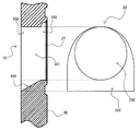
連通管262は、シリンダ22の端部に向かって上方に延伸しており、その上端には、図3に示すように、連通管出口部263が設けられている。連通管出口部263は、上部形状264aが曲線状に突出した突出形状であり、かつ、下部形状264bが矩形状である連通開口264を有している。図3に示す例では、上部形状264aは略半円形状であり、下部形状264bは横長の略長方形状である。なお、上部形状264aは、半楕円形状であってもよいし、放物線状等のようなその他の曲線状であってもよい。同様に、下部形状264bは、正方形状であってもよい。図2に示すように、連通管262は、シリンダヘッド23とバルブプレート30との間に挟持されているように設けられている。
The
図3に示すように、連通管出口部263における連通開口264の周囲は、平坦な端面265となっている。この端面265は、図4に示すように、バルブプレート30の連通管側表面31(前記他方の面)に当接する面となる。
As shown in FIG. 3, the periphery of the
バルブプレート30は、例えば、金属焼結体(焼結金属)等の金属製であって、図4に示す吸入孔33(図中一点鎖線で囲んだ孔部)と、図4には図示しない吐出孔が形成されている。バルブプレート30のシリンダ側表面32(前記一方の面)には、吸入孔33を覆うように吸入リード27が設けられており、この吸入リード27が吸入孔33を開閉する。また、図示しない吐出孔は図示しない吐出リードにより開閉される。連通管出口部263は、図示しないガスケット(または公知のシール部材)を介して、バルブプレート30の吸入孔33に連結されている。なお、バルブプレート30の具体的な構成については後述する。
The
前記構成の密閉型圧縮機10の動作について説明する。まず、図示しない商用電源から電動要素12に電力を供給することによって、電動要素12の回転子を回転させる。回転子は、シャフト21を回転させるので、主軸部の回転により偏心軸も回転する。偏心軸の主軸部に対する偏心運動は、コンロッド25からピストン24に伝達される。これにより、ピストン24は、シリンダ22のボアー内を往復摺動する。
The operation of the
ピストン24の往復摺動により、図示しない冷凍サイクル(冷却回路、冷媒回路)から冷媒ガスが密閉容器11内に導入され、密閉容器11内に開放される。開放された冷媒ガスは、吸入口からサクションマフラー26内に吸引される。吸引された冷媒ガスは、消音空間261に開放された後、連通管262からバルブプレート30の吸入孔33を介して圧縮室(シリンダ22およびピストン24によって隔離された空間)に対して間欠的に吸入される。圧縮室に吸入された冷媒ガスは、当該圧縮室内で圧縮され、バルブプレート30の吐出孔を介してシリンダヘッド23の吐出空間に吐出される。吐出空間に吐出された冷媒ガスは、図示しない冷凍サイクルに排出される。そして、冷媒ガスは、冷凍サイクル内を循環して、再び密閉容器11内に導入される。
By reciprocating sliding of the
[バルブプレート]
次に、バルブプレート30の具体的な構成について、図4に加えて、図5〜図7を参照して具体的に説明する。[Valve plate]
Next, a specific configuration of the
前述した通り、図5および図6に示すように、バルブプレート30には、吸入孔33および吐出孔34が形成されている。図5は、バルブプレート30を連通管側表面31から見た斜視図であり、図6は、バルブプレート30をシリンダ側表面32から見た斜視図である。
As described above, as shown in FIGS. 5 and 6, the
図4および図5に示すように、吸入孔33における連通管262側(シリンダ22とは反対側)の開口は、吸入入口側開口332(図4では点線で囲んだ開口領域)となっている。図4および図6に示すように、吸入孔33におけるシリンダ22側の開口は、吸入出口側開口333(図4では破線で囲んだ領域)となっている。また、連通管出口部263は、縦方向に沿った連通管262本体から見て、横方向に延出するように形成されており、吸入孔33の吸入入口側開口332に連結している。なお、図4に示すように、連通管出口部263と吸入孔33とによって、冷媒ガスが流通する吸入流路331が構成されている。
As shown in FIGS. 4 and 5, the opening on the
吸入孔33における吸入出口側開口333(シリンダ側開口)は、その形状が凹部の無い閉曲線状となっている。閉曲線状の具体的な形状は特に限定されないが、一般的には、円形状または楕円形状であればよい。本実施の形態では、吸入出口側開口333は、図6に示すように、略円形状になっている。一方、吸入孔33における吸入入口側開口332(連通管側開口)は、連通開口264と相似形状となっている。本実施の形態では、連通開口264は、上部形状264aが略半円形状であり下部形状264bが横長の略長方形状であるので、吸入入口側開口332も上部が略半円形状で下部が長方形状となっている。なお、吸入入口側開口332は、本実施の形態では、連通開口264と同じサイズであるが、少し小さ目のサイズであってもよい。
The suction outlet side opening 333 (cylinder side opening) in the
バルブプレート30と連通管262とが連結している状態では、図4に示すように、連通開口264の上側の周面と、吸入孔33の上側の周面とが対応している。特に本実施の形態では、連通開口264の上側の周面と吸入孔33の上側の周面とは、実質的に段差のない一つの面を形成している。一方、連通開口264の下側の周面は、吸入孔33の吸入出口側開口333の下側の周面よりも下側に位置している。ここで、吸入孔33の下側の周面には、図4、図5および図7に示すように、湾曲部334および傾斜部335が含まれているので、連通開口264の下側の周面と吸入孔33の下側の周面とは、傾斜部335および湾曲部334によって、実質的に一つの連続した面を形成している。
In the state where the
湾曲部334は、吸入入口側開口332から吸入出口側開口333に向かって湾曲する湾曲面となっている。また、傾斜部335は、吸入入口側開口332から吸入出口側開口333に向かって傾斜する傾斜面となっている。本実施の形態では、図4および図7に示すように、連通管262側に傾斜部335が位置し、シリンダ22側に湾曲部334が位置している。傾斜部335は、吸入入口側開口332から見て上方に向かって急峻な傾斜面となっており、湾曲部334は、この傾斜部335に連続する面であって、吸入出口側開口333の下側の周面において上方に向かって少し盛り上がるように湾曲した面となっている。したがって、図7に示すように、吸入孔33を連通管262側からシリンダ22側に向かって見れば、手前側に傾斜部335が位置し奥側に湾曲部334が位置することになる。
The
湾曲部334または傾斜部335の具体的な構成は特に限定されない。例えば、湾曲部334の湾曲の程度は、吸入孔33の直径、吸入入口側開口332の断面積と吸入出口側開口333の断面積との関係、バルブプレート30の厚み(すなわち吸入孔33の延伸方向の長さ)、密閉型圧縮機10の圧縮性能等の諸条件に応じて適宜設定することができる。同様に、傾斜部335の具体的な傾斜角も特に限定されないが、一般的には、吸入孔33(特に吸入出口側開口333)の軸心に対して、35〜55°の範囲内であればよく、45°±5°の範囲内であることがより好ましい。
The specific configuration of the bending
なお、本発明においては、吸入孔33の下側の周面の形状は、図4、図5、および図7に示すような、湾曲部334および傾斜部335の双方を含む構成に限定されない。例えば、図8に示すように、吸入孔33の下側の周面が傾斜部335のみとなっている構成であってもよいし、図9に示すように、吸入孔33の下側の周面が湾曲部334のみとなっている構成であってもよい。さらに図示しないが、湾曲部334および傾斜部335以外の面、例えば、吸入孔33の延伸方向に沿った平坦な面を含んでもよいし、他の構成を含んでもよい。
In the present invention, the shape of the lower peripheral surface of the
本発明においては、吸入孔33の吸入入口側開口332の形状が連通開口264と相似形状であって、バルブプレート30と連通管262とが、連通管出口部263の連通開口264の上側の周面と、吸入孔33の上側の周面とを対応させた状態で連結されていればよく、吸入孔33の形状については、冷媒ガスの吸入抵抗を有効に抑制できるのであれば、どのような形状でも採用することができる。
In the present invention, the shape of the suction inlet side opening 332 of the
このように、本実施の形態に係るバルブプレート30では、吸入孔33の基本的な形状が、円形状または楕円形状等のように、凹部の無い閉曲線状となっている。そのため、バルブプレート30を製造するための金型を製作する際に、複雑な形状を造形する必要がなく、金型製作の複雑化を回避することができる。それゆえ、バルブプレート30そのものも容易に製造することができ、製造コストの増大も回避または抑制することができる。
As described above, in the
また、吸入孔33の吸入出口側開口333(シリンダ側開口)の形状は、前記の通り閉曲線状となっているが、吸入入口側開口332(連通管側開口)の形状は、連通管出口部263の連通開口264と相似形状となっている。連通開口264は、上部形状264aが曲線状に突出した突出形状であり、かつ、下部形状264bが矩形状である。
The shape of the suction outlet side opening 333 (cylinder side opening) of the
連通管出口部263から吸入孔33に向かって冷媒ガスが吸入される際には、冷媒ガスの流れは速くなるが、吸入孔33が前記のような構成であれば、従来の略U字形状の吸入孔83とは異なり、吸入孔33の中央部と両側部とで冷媒ガスの流速に違いが生じにくくなる。そのため、連通管出口部263と吸入孔33との連結部分で冷媒ガスの淀みを抑制することが可能となり、連通管262からシリンダ22内に向かって冷媒ガスを円滑に流入させることができる。その結果、吸入孔33の近傍での冷媒ガスの吸入抵抗の増加(これによる吸入損失の増加)を有効に抑制することができる。
When the refrigerant gas is sucked from the
しかも、本実施の形態では、吸入孔33の下側の周面には、吸入入口側開口332(連通管側開口)から吸入出口側開口333(シリンダ側開口)に向かって湾曲する湾曲部334、または、吸入入口側開口332(連通管側開口)から吸入出口側開口333(シリンダ側開口)に向かって傾斜する傾斜部335、もしくは、湾曲部334および傾斜部335の両方が設けられている。
Moreover, in the present embodiment, a
連通管出口部263および吸入孔33により構成される吸入流路331は、連通管262の延伸方向(縦方向、上下方向)に対して、直交(または交差)する方向(横方向、水平方向)に延伸していることになる。つまり、サクションマフラー26から連通管262を介して直線状に流れる冷媒ガスは、連通管262の上端に達したところ(連通管出口部263)において、折れ曲がる方向(吸入流路331)に流れることになる。この場合、吸入流路331の上側の周面近傍では、冷媒ガスの流速は相対的に高くなるが、下側の周面近傍では、冷媒ガスが淀みやすく、その流速は相対的に低くなる。
The
これに対して、湾曲部334および傾斜部335の少なくとも一方が吸入孔33の下側の周面に設けられていれば、これら湾曲部334または傾斜部335に沿って冷媒ガスがシリンダ22側に導かれる。そのため、下側の周面近傍で冷媒ガスの淀みが良好に抑制されて、その流速の低下も抑制される。これにより、吸入流路331全体として冷媒ガスの流れを促進することができるので、冷媒ガスの吸入抵抗の増加、並びに、吸入損失の増加を有効に抑制することができる。
On the other hand, if at least one of the
このように、前記構成のバルブプレート30であれば、冷媒ガスの吸入抵抗および吸入損失を抑制することができるため、冷媒ガスの単位時間当たりの吸入質量(冷媒循環量)を大きくすることができる。その結果、より効率化された密閉型圧縮機10を提供することができる。
Thus, with the
[吸入孔の断面積]
ここで、本実施の形態では、吸入孔33のうち、吸入入口側開口332の方が断面積が大きく、吸入出口側開口333の方が断面積が小さい。したがって、吸入孔33は、吸入入口側開口332(連通管側開口)から吸入出口側開口333(シリンダ側開口)に向けて、徐々に断面積が小さくなる(狭くなる)ように形成されている。この点について、特許文献1に開示される従来の構成と対比しながら、図4および図11を参照して具体的に説明する。[Cross-sectional area of suction hole]
Here, in the present embodiment, among the suction holes 33, the suction
従来のバルブプレート80は、図11に示すように、本実施の形態と同様に、シリンダ22およびシリンダヘッド23の間に位置し、吸入孔83は、連通管862の連通管出口部863に連結している。なお、図11には、シリンダ22内に吸入バルブ羽根88(suction valve vane,本実施の形態における吸入リード27に対応)も図示している。
As shown in FIG. 11, the
従来のバルブプレート80は、吸入孔83が略U字形状であることから、その製造が容易ではない。また、従来のバルブプレート80では、移行部Tが形成されるとしても、流路の断面形状が略円形状(連通管出口部863)から略U字形状(吸入孔83)に急激に変化する。これにより、冷媒ガスが吸入孔83からシリンダ22内に流入する際に、冷媒ガスの吸入抵抗が増加する。
The
そこで、吸入抵抗の増加を回避するために、連通管862から吸入孔83までの流路(吸入流路831も含む)の断面形状を略円形状にする構成が考えられる。しかしながら、この構成では、シリンダ22に吸入される冷媒ガスの量と、圧縮動作時に吸入バルブ羽根88(吸入リード27)に生じる応力との双方を好適化することができない。
Thus, in order to avoid an increase in suction resistance, a configuration in which the cross-sectional shape of the flow path (including the suction flow path 831) from the
シリンダ22内で冷媒ガスを圧縮するときには、吸入バルブ羽根88(吸入リード27)における吸入孔83に接する部位に対して、円周方向に沿って応力が発生する。吸入孔83の径が相対的に小さければ、圧縮時に吸入バルブ羽根88に生じる応力は低減できる。しかしながら、吸入孔83が小さいことから、シリンダ22内に吸入される冷媒ガスの量が少なくなるため、圧縮効率が低下する。一方、吸入孔83の径が相対的に大きければ、シリンダ22内に吸入される冷媒ガスの量を増やすことができる。しかしながら、圧縮時に吸入バルブ羽根88に生じる応力が大きくなるため、吸入バルブ羽根88の折損につながるおそれがある。
When the refrigerant gas is compressed in the
これに対して、本実施の形態では、前記の通り、吸入孔33が基本的に円形状または楕円形状であって、連通管262側の形状が連通開口264と相似形状である上に、シリンダ22に向けて徐々に断面積が小さくなっている。これにより、冷媒ガスの流れに勢いを与えることができるので、吸入孔33に対する冷媒ガスの流れをさらに促進し、好適な量の冷媒ガスをシリンダ22に導入することができる。しかも、吸入孔33のシリンダ22側の断面積(吸入出口側開口333の大きさ)は、相対的に小さいため、圧縮時に吸入リード27に生じる応力を有効に低減することができる。さらに、冷媒ガスの流れが促進されると、吸入リード27を迅速に開くことができるので、冷媒ガスの吸入抵抗をさらに抑制できる。それゆえ、より一層効率化された密閉型圧縮機10を提供することができる。
On the other hand, in the present embodiment, as described above, the
吸入入口側開口332の断面積と吸入出口側開口333の断面積との関係は特に限定されないが、本実施の形態では、吸入入口側開口332の断面積は、吸入出口側開口333の断面積に対して150〜250%の範囲内であることが好ましく、160〜200%の範囲内がより好ましい。これら開口の断面積の関係が、上記の範囲内にあることで、吸入流路331の断面積の変化を好適化することができる。そのため、連通管出口部263から吸入孔33に冷媒ガスが流入したときに、吸入孔33の有効面積を十分に確保した状態で、吸入抵抗の増加を抑制することができる。その結果、単位時間当たりの冷媒ガスの吸入質量(冷媒循環量)を大きくすることが可能となり、密閉型圧縮機10をより効率化することができる。
The relationship between the sectional area of the suction
これに対して、吸入入口側開口332の断面積が、吸入出口側開口333の断面積に対して150%未満であると、冷媒ガスの循環量が多くなったときに吸入損失が有意に増加してしまう。一方、吸入入口側開口332の断面積が、吸入出口側開口333の断面積に対して250%を超えると、冷媒ガスの循環量が少なくなったときに吸入損失が有意に増加してしまう。それゆえ、吸入入口側開口332の断面積が、吸入出口側開口333の断面積に対して前記の範囲から外れると、密閉型圧縮機10の効率が低下する。
On the other hand, when the cross-sectional area of the suction
このように、本発明に係る密閉型圧縮機は、密閉容器内に潤滑油を貯留するとともに、電動要素と、この電動要素によって駆動され冷媒ガスを圧縮する圧縮要素とを収容し、この圧縮要素は圧縮室を形成するシリンダと、このシリンダの端部を封止するとともに、吸入孔および吐出孔とが形成されたバルブプレートと、吸入孔を開閉する吸入リードと、内部に消音空間を有し連通管を備えているサクションマフラーと、シリンダヘッドと、を備え、連通管は、吸入孔の軸心に対して水平方向に延出するように形成されて、吸入孔に連通する連通管出口部を有し、連通管出口部は、半円形状と、前記吸入孔の軸心に対して垂直下方向に延出した略四角形状と、を組み合わせた形状として形成され、バルブプレートの吸入孔は、円形状であり、バルブプレートに設けられた吸入入口(吸入側開口)は、連通管出口部と相似形状にて形成されたものである。 As described above, the hermetic compressor according to the present invention stores lubricating oil in a hermetic container, and houses an electric element and a compression element that is driven by the electric element and compresses refrigerant gas. Has a cylinder that forms a compression chamber, a valve plate that seals the end of the cylinder, a suction hole and a discharge hole, a suction lead that opens and closes the suction hole, and a silencing space inside. A suction muffler having a communication pipe and a cylinder head, and the communication pipe is formed to extend in the horizontal direction with respect to the axial center of the suction hole, and is connected to the suction hole. The communication pipe outlet portion is formed as a combination of a semicircular shape and a substantially quadrangular shape extending vertically downward with respect to the axis of the suction hole. Is circular, Suction inlet provided Bupureto (suction side opening) are those formed by the similar shape communicating tube outlet.
また、本発明に係る密閉型圧縮機においては、連通管出口部の端面から吸入孔に向かって冷媒ガスを導く吸入流路が形成され、この吸入流路には、バルブプレートの吸入入口の端面から吸入孔に向かう湾曲部または傾斜部が設けられていることが好ましい。 Further, in the hermetic compressor according to the present invention, a suction flow path for introducing the refrigerant gas from the end face of the communication pipe outlet portion toward the suction hole is formed, and the suction flow path has an end face of the suction inlet of the valve plate. It is preferable that a curved portion or an inclined portion that is directed to the suction hole is provided.
このような構成であれば、冷媒ガスが吸入流路を介して整流化されてシリンダ内に導入される。それゆえ、冷媒ガスを円滑にシリンダに内に吸入することができ、冷媒ガスの吸入抵抗が有効に抑えることができる。その結果、冷媒ガスの単位時間当たりの吸入質量(冷媒循環量)は大きくなるので、効率の高い密閉型圧縮機を提供することができる。 With such a configuration, the refrigerant gas is rectified through the suction passage and introduced into the cylinder. Therefore, the refrigerant gas can be smoothly sucked into the cylinder, and the refrigerant gas suction resistance can be effectively suppressed. As a result, since the suction mass (refrigerant circulation amount) per unit time of the refrigerant gas is increased, a highly efficient hermetic compressor can be provided.
さらに、このような構成であれば、吸入孔を大きくしなくてもよいため、圧縮時に吸入リードの吸入孔に接する部分に発生する円周方向に沿った応力を増大させないことができる。それゆえ、吸入リードの信頼性を高めることができるので、より信頼性の高い密閉型圧縮機を提供することができる。 Further, with such a configuration, it is not necessary to enlarge the suction hole, so that it is possible to prevent an increase in stress along the circumferential direction that occurs at the portion of the suction lead that contacts the suction hole during compression. Therefore, since the reliability of the suction lead can be improved, a more reliable hermetic compressor can be provided.
(実施の形態2)
本実施の形態2では、前記実施の形態1で説明した密閉型圧縮機10を備える冷凍装置の一例について、図10を参照して具体的に説明する。(Embodiment 2)
In the second embodiment, an example of a refrigeration apparatus including the
本発明に係る密閉型圧縮機10は、冷凍サイクルまたはこれと実質同等な構成を有する各種機器(冷凍装置)に広く好適に用いることができる。具体的には、例えば、冷蔵庫(家庭用冷蔵庫、業務用冷蔵庫)、製氷機、ショーケース、除湿器、ヒートポンプ式給湯機、ヒートポンプ式洗濯乾燥機、自動販売機、エアーコンディショナー、空気圧縮機等を挙げることができるが、特に限定されない。本実施の形態では、本発明に係る密閉型圧縮機10の適用例として、図10に示す物品貯蔵装置40を挙げて、冷凍装置の具体的な構成を説明する。
The
図10に示す物品貯蔵装置40は、貯蔵装置本体41、凝縮器51、減圧装置52、蒸発器53、送風機54、配管55、および密閉型圧縮機10等を備えている。凝縮器51、減圧装置52、蒸発器53、および密閉型圧縮機10は、配管55により環状に連結されて冷凍サイクルを構成している。なお、本実施の形態では、冷媒ガスとしてR600aを用いている。
An
貯蔵装置本体41の前方には、第一貯蔵室42および第二貯蔵室43が設けられ、後方には、前記冷凍サイクル(凝縮器51、減圧装置52、蒸発器53、送風機54、密閉型圧縮機10、および配管55)、並びに送風機54が設けられている。第一貯蔵室42および第二貯蔵室43は、それぞれ前面が開口となっており、前面以外の周囲が断熱材により覆われている。第一貯蔵室42の前面には、前記開口に対応する第一扉44が設けられ、第二貯蔵室43の前面には、前記開口に対応する第二扉45が設けられている。第一扉44および第二扉45は、いずれも断熱性を有しており、前記開口を開閉可能とするように設けられている。また、第一貯蔵室42および第二貯蔵室43は、前方の連絡通路46と後方の連絡通路47介して連通している。
A
蒸発器53は、貯蔵装置本体41の後方で第一貯蔵室42の内部に配置されている。また、送風機54は、第一貯蔵室42内で蒸発器53の後方に配置されている。冷凍サイクルが動作することによって蒸発器53は第一貯蔵室42内を冷却し、これによって冷気が生じる。送風機54は、生じた冷気を図中矢印Faで示すように第一貯蔵室42内で循環させる。また、前述したように、第一貯蔵室42および第二貯蔵室43は、前後の連絡通路46および47によって連通しているので、第一貯蔵室42の冷気の一部は、図中矢印Fbで示すように、連絡通路46および47により第二貯蔵室43内も循環する。それゆえ、第一貯蔵室42および第二貯蔵室43の内部が冷却される。
The
本実施の形態では、前記冷凍サイクルに前記実施の形態1で説明した密閉型圧縮機10が用いられている。この密閉型圧縮機10は、バルブプレート30を容易に製造できるため、良好な生産性を有しながら効率的で安価なものとなっている。このような密閉型圧縮機10を搭載することにより、物品貯蔵装置40は、効率的な冷却運転が可能となる。その結果、消費電力(量)を有効に抑制することができる。
In the present embodiment, the
本発明について、実施例および比較例に基づいてより具体的に説明するが、本発明はこれに限定されるものではない。当業者は本発明の範囲を逸脱することなく、種々の変更、修正、および改変を行うことができる。 The present invention will be described more specifically based on examples and comparative examples, but the present invention is not limited to this. Those skilled in the art can make various changes, modifications, and alterations without departing from the scope of the present invention.
(実施例)
冷媒ガスとしてR600aを封入した冷凍サイクルに、前記実施の形態1で説明した密閉型圧縮機10を組み込んだ。密閉型圧縮機10を凝縮温度25〜60℃かつ蒸発温度−20〜−40℃の条件で動作させて、シリンダ22の内圧(単位:kPa)とクランク角(単位:°)との関係を検証した。その結果を図12上のグラフに示す。(Example)
The
(比較例)
前記実施例と同様にR600aを封入した冷凍サイクルに、従来の密閉型圧縮機(図11参照)を組み込んだ。この従来の密閉型圧縮機を前記実施例と同様の条件で動作させ、シリンダ22の内圧とクランク角との関係を検証した。その結果を図12下のグラフに示す。(Comparative example)
A conventional hermetic compressor (see FIG. 11) was incorporated into the refrigeration cycle in which R600a was sealed in the same manner as in the previous example. This conventional hermetic compressor was operated under the same conditions as in the previous embodiment, and the relationship between the internal pressure of the
(実施例および比較例の対比)
図12に示す上下のグラフには、低圧側の設定圧力を破線で示しており、この破線より下になる領域の面積が吸入損失に相当する。比較例すなわち従来の密閉型圧縮機に比べて、実施例すなわち本発明に係る密閉型圧縮機10の方が、破線より下の面積が明らかに小さくなっている。それゆえ、本発明によれば吸入損失を有効に抑制することができる。(Contrast of Examples and Comparative Examples)
In the upper and lower graphs shown in FIG. 12, the set pressure on the low pressure side is indicated by a broken line, and the area of the region below the broken line corresponds to the suction loss. Compared with the comparative example, that is, the conventional hermetic compressor, the area under the broken line is clearly smaller in the example, that is, the
上記説明から、当業者にとっては、本発明の多くの改良や他の実施形態が明らかである。従って、上記説明は、例示としてのみ解釈されるべきであり、本発明を実行する最良の態様を当業者に教示する目的で提供されたものである。本発明の精神を逸脱することなく、その構造及び/又は機能の詳細を実質的に変更できる。 From the foregoing description, many modifications and other embodiments of the present invention are obvious to one skilled in the art. Accordingly, the foregoing description should be construed as illustrative only and is provided for the purpose of teaching those skilled in the art the best mode of carrying out the invention. The details of the structure and / or function may be substantially changed without departing from the spirit of the invention.
本発明は、密閉型圧縮機の分野に好適に用いることができるだけでなく、当該密閉型圧縮機を用いた冷凍サイクルまたはこれと実質同等な構成を有する各種機器に広く好適に用いることができる。 The present invention can be suitably used not only in the field of hermetic compressors, but also widely and widely used in refrigeration cycles using the hermetic compressors or various devices having substantially the same configuration.
10 密閉型圧縮機
11 密閉容器
12 電動要素
13 圧縮要素
14 潤滑油
22 シリンダ
23 シリンダヘッド
24 ピストン
26 サクションマフラー
27 吸入リード
30 バルブプレート
33 吸入孔
34 吐出孔
40 物品貯蔵装置(冷凍装置)
51 凝縮器
52 減圧装置
53 蒸発器
54 送風機
262 連通管
263 連通管出口部
264 連通開口
264a 上部形状
264b 下部形状
265 連通管出口部の端面
331 吸入流路
332 吸入入口側開口(連通管側開口)
333 吸入出口側開口(シリンダ側開口)
334 湾曲部
335 傾斜部
DESCRIPTION OF
REFERENCE SIGNS
333 Suction outlet side opening (cylinder side opening)
334
Claims (4)
当該密閉容器内に収容される電動要素と、
前記密閉容器内に収容され、前記電動要素により駆動され冷媒を圧縮する圧縮要素と、を備え、
前記圧縮要素は、
圧縮室を形成するシリンダと、
前記シリンダの一方の端部を封止するとともに、吸入孔および吐出孔が形成されたバルブプレートと、
前記吸入孔を開閉する吸入リードと、
前記シリンダよりも下方に位置し、内部に消音空間を有し、前記吸入孔に連結される連通管を備えるサクションマフラーと、
を備え、
前記連通管は、前記サクションマフラーから前記シリンダの端部に向かって上方に延伸し、その上端に、前記吸入孔に連通する連通管出口部が設けられ、
前記連通管出口部は、上部形状が曲線状に突出した突出形状であり、かつ、下部形状が矩形状である連通開口を有し、
前記吸入孔は、前記シリンダ側開口の形状が凹部の無い閉曲線状であり、前記連通管側開口の形状が前記連通管出口部の連通開口と相似形状であり、
前記バルブプレートおよび前記連通管は、前記連通管出口部の連通開口の上側の周面と、前記吸入孔の上側の周面とを対応させた状態で連結されており、
前記連通管側開口から前記シリンダ側開口に向かって湾曲する湾曲部、または、前記連通管側開口から前記シリンダ側開口に向かって傾斜する傾斜部が、前記吸入孔の下側の周面のみに含まれている、
密閉型圧縮機。 A sealed container in which lubricating oil is stored;
An electric element housed in the sealed container;
A compression element housed in the sealed container and driven by the electric element to compress the refrigerant,
The compression element is
A cylinder forming a compression chamber;
A valve plate that seals one end of the cylinder and has a suction hole and a discharge hole;
A suction lead for opening and closing the suction hole;
A suction muffler that is located below the cylinder, has a sound deadening space inside, and includes a communication pipe connected to the suction hole;
With
The communication pipe extends upward from the suction muffler toward the end of the cylinder, and a communication pipe outlet portion communicating with the suction hole is provided at an upper end of the communication pipe.
The communication pipe outlet portion has a protruding shape in which the upper shape protrudes in a curved shape, and a communication opening whose lower shape is a rectangular shape,
The suction hole has a closed curved shape in which the cylinder side opening has no recess, and the shape of the communication pipe side opening is similar to the communication opening of the communication pipe outlet part,
The valve plate and the communication pipe are connected in a state where the upper peripheral surface of the communication opening of the communication pipe outlet and the upper peripheral surface of the suction hole correspond to each other.
A curved part that curves from the communication pipe side opening toward the cylinder side opening or an inclined part that inclines from the communication pipe side opening toward the cylinder side opening is only on the lower peripheral surface of the suction hole. Included ,
Hermetic compressor.
請求項1に記載の密閉型圧縮機。 The suction hole is formed so that a cross-sectional area gradually decreases from the communication pipe side opening toward the cylinder side opening.
The hermetic compressor according to claim 1.
前記連通管出口部の連通開口の上部は、半円形状または半楕円形状である、
請求項1または2に記載の密閉型圧縮機。 The cylinder side opening of the suction hole is circular or elliptical,
The upper part of the communication opening of the communication pipe outlet is a semicircular or semi-elliptical shape.
The hermetic compressor according to claim 1 or 2 .
冷凍装置。 A refrigeration cycle including the hermetic compressor according to any one of claims 1 to 3 is provided.
Refrigeration equipment.
Applications Claiming Priority (3)
| Application Number | Priority Date | Filing Date | Title |
|---|---|---|---|
| JP2012271955 | 2012-12-13 | ||
| JP2012271955 | 2012-12-13 | ||
| PCT/JP2013/007346 WO2014091764A1 (en) | 2012-12-13 | 2013-12-13 | Hermetic compressor and refrigeration device |
Publications (2)
| Publication Number | Publication Date |
|---|---|
| JPWO2014091764A1 JPWO2014091764A1 (en) | 2017-01-05 |
| JP6286364B2 true JP6286364B2 (en) | 2018-02-28 |
Family
ID=50934070
Family Applications (1)
| Application Number | Title | Priority Date | Filing Date |
|---|---|---|---|
| JP2014551898A Active JP6286364B2 (en) | 2012-12-13 | 2013-12-13 | Hermetic compressor and refrigeration system |
Country Status (4)
| Country | Link |
|---|---|
| US (1) | US10167860B2 (en) |
| JP (1) | JP6286364B2 (en) |
| CN (1) | CN104603461B (en) |
| WO (1) | WO2014091764A1 (en) |
Families Citing this family (4)
| Publication number | Priority date | Publication date | Assignee | Title |
|---|---|---|---|---|
| WO2016108767A2 (en) * | 2014-12-29 | 2016-07-07 | Kulthorn Premier Company Limited | Valve plate with modified suction holes to increase refrigerant flow for compressor |
| EP3455497A1 (en) | 2016-05-10 | 2019-03-20 | Arçelik Anonim Sirketi | A hermetic compressor with improved sealing |
| DE102017108186A1 (en) * | 2017-04-18 | 2018-10-18 | Gardner Denver Deutschland Gmbh | Mixing valve arrangement for a hydraulic system, as well as oil cooling system and compressor system with this |
| CN108194325B (en) * | 2017-12-28 | 2019-11-26 | 芜湖欧宝机电有限公司 | The manufacturing method of high-efficient low-noise piston compressor valve plate |
Family Cites Families (12)
| Publication number | Priority date | Publication date | Assignee | Title |
|---|---|---|---|---|
| IT1278603B1 (en) * | 1994-11-03 | 1997-11-24 | Necchi Compressori | HERMETIC MOTOR-COMPRESSOR |
| KR0156720B1 (en) * | 1995-07-27 | 1999-03-20 | 김광호 | Reciprocating compressor |
| IT241575Y1 (en) * | 1996-11-19 | 2001-05-09 | Zanussi Elettromecc | REFRIGERATED COMPRESSOR WITH HEAD AND SILENCER PERFECTED |
| DE19915918C2 (en) * | 1999-04-09 | 2001-05-31 | Danfoss Compressors Gmbh | Refrigerant compressor and method for its assembly |
| DE19923733C2 (en) * | 1999-05-22 | 2002-06-20 | Danfoss Compressors Gmbh | Suction gas line for a refrigerant compressor |
| DE19923734C2 (en) | 1999-05-22 | 2001-03-29 | Danfoss Compressors Gmbh | Suction silencer for a hermetically sealed compressor |
| US6524080B2 (en) * | 2000-04-11 | 2003-02-25 | R. K. Dewan & Co. | Hermetically sealed compressors |
| KR100390492B1 (en) * | 2000-07-13 | 2003-07-04 | 엘지전자 주식회사 | Apparatus for reducing noise of suction muffler in compressor |
| BR0003292A (en) * | 2000-07-17 | 2002-02-26 | Brasil Compressores S A | Arrangement of suction and discharge valves for small hermetic compressor |
| JP4968343B2 (en) * | 2008-01-17 | 2012-07-04 | パナソニック株式会社 | Compressor |
| JP5560580B2 (en) * | 2009-04-10 | 2014-07-30 | パナソニック株式会社 | Hermetic compressor |
| JP2012107575A (en) * | 2010-11-18 | 2012-06-07 | Panasonic Corp | Hermetic compressor |
-
2013
- 2013-12-13 CN CN201380044885.9A patent/CN104603461B/en active Active
- 2013-12-13 JP JP2014551898A patent/JP6286364B2/en active Active
- 2013-12-13 WO PCT/JP2013/007346 patent/WO2014091764A1/en active Application Filing
- 2013-12-13 US US14/423,955 patent/US10167860B2/en active Active
Also Published As
| Publication number | Publication date |
|---|---|
| US10167860B2 (en) | 2019-01-01 |
| CN104603461B (en) | 2017-03-01 |
| US20150219085A1 (en) | 2015-08-06 |
| CN104603461A (en) | 2015-05-06 |
| WO2014091764A1 (en) | 2014-06-19 |
| JPWO2014091764A1 (en) | 2017-01-05 |
Similar Documents
| Publication | Publication Date | Title |
|---|---|---|
| KR100821796B1 (en) | Hermetic compressor | |
| JP6286364B2 (en) | Hermetic compressor and refrigeration system | |
| JP6259498B2 (en) | Hermetic compressor and refrigeration system | |
| JP5560580B2 (en) | Hermetic compressor | |
| JP5816791B2 (en) | Hermetic compressor | |
| JP2006144729A (en) | Hermetically-sealed compressor | |
| JP2017145787A (en) | Hermetic type compressor and refrigeration device using the same | |
| WO2014017051A1 (en) | Sealed refrigeration compressor and refrigeration device provided with same | |
| JP2013231429A (en) | Hermetic compressor | |
| JP2015025363A (en) | Hermetic compressor and refrigerator | |
| JP2015140737A (en) | Hermetic compressor and refrigerator using same | |
| JP2015040471A (en) | Hermetic type compressor and refrigerator using the same | |
| JP2012021400A (en) | Sealed type compressor and refrigerator equipped therewith | |
| JP2011058383A (en) | Hermetic compressor and refrigerator using the same | |
| JP2009191764A (en) | Hermetic compressor | |
| JP2012102610A (en) | Hermetic compressor, and refrigeration device | |
| JP2012159071A (en) | Hermetic compressor and refrigerating device | |
| JP2015034477A (en) | Hermetic compressor and refrigerator including the same | |
| JP2016169604A (en) | Hermetic type compressor and freezer | |
| JP2013050074A (en) | Hermetic compressor | |
| JP2014152749A (en) | Rotary compressor | |
| KR20230077856A (en) | Cylinder device for linear compressor | |
| JP2013124641A (en) | Compressor | |
| KR200317644Y1 (en) | Inlet muffler of a compressor | |
| JP2012031769A (en) | Hermetic compressor and refrigerator using the same |
Legal Events
| Date | Code | Title | Description |
|---|---|---|---|
| A621 | Written request for application examination |
Free format text: JAPANESE INTERMEDIATE CODE: A621 Effective date: 20161202 |
|
| A711 | Notification of change in applicant |
Free format text: JAPANESE INTERMEDIATE CODE: A711 Effective date: 20170210 |
|
| A711 | Notification of change in applicant |
Free format text: JAPANESE INTERMEDIATE CODE: A711 Effective date: 20170331 |
|
| A131 | Notification of reasons for refusal |
Free format text: JAPANESE INTERMEDIATE CODE: A131 Effective date: 20171003 |
|
| A521 | Request for written amendment filed |
Free format text: JAPANESE INTERMEDIATE CODE: A523 Effective date: 20171222 |
|
| TRDD | Decision of grant or rejection written | ||
| A01 | Written decision to grant a patent or to grant a registration (utility model) |
Free format text: JAPANESE INTERMEDIATE CODE: A01 Effective date: 20180130 |
|
| A61 | First payment of annual fees (during grant procedure) |
Free format text: JAPANESE INTERMEDIATE CODE: A61 Effective date: 20180205 |
|
| R150 | Certificate of patent or registration of utility model |
Ref document number: 6286364 Country of ref document: JP Free format text: JAPANESE INTERMEDIATE CODE: R150 |
|
| R250 | Receipt of annual fees |
Free format text: JAPANESE INTERMEDIATE CODE: R250 |
|
| R250 | Receipt of annual fees |
Free format text: JAPANESE INTERMEDIATE CODE: R250 |
|
| R250 | Receipt of annual fees |
Free format text: JAPANESE INTERMEDIATE CODE: R250 |
|
| R250 | Receipt of annual fees |
Free format text: JAPANESE INTERMEDIATE CODE: R250 |