JP6285403B2 - Cell control device and production system for predicting failure of manufacturing machine - Google Patents
Cell control device and production system for predicting failure of manufacturing machine Download PDFInfo
- Publication number
- JP6285403B2 JP6285403B2 JP2015233408A JP2015233408A JP6285403B2 JP 6285403 B2 JP6285403 B2 JP 6285403B2 JP 2015233408 A JP2015233408 A JP 2015233408A JP 2015233408 A JP2015233408 A JP 2015233408A JP 6285403 B2 JP6285403 B2 JP 6285403B2
- Authority
- JP
- Japan
- Prior art keywords
- failure
- manufacturing machine
- control device
- manufacturing
- time
- Prior art date
- Legal status (The legal status is an assumption and is not a legal conclusion. Google has not performed a legal analysis and makes no representation as to the accuracy of the status listed.)
- Active
Links
Images


Classifications
-
- G—PHYSICS
- G05—CONTROLLING; REGULATING
- G05B—CONTROL OR REGULATING SYSTEMS IN GENERAL; FUNCTIONAL ELEMENTS OF SUCH SYSTEMS; MONITORING OR TESTING ARRANGEMENTS FOR SUCH SYSTEMS OR ELEMENTS
- G05B19/00—Programme-control systems
- G05B19/02—Programme-control systems electric
- G05B19/418—Total factory control, i.e. centrally controlling a plurality of machines, e.g. direct or distributed numerical control [DNC], flexible manufacturing systems [FMS], integrated manufacturing systems [IMS], computer integrated manufacturing [CIM]
- G05B19/41865—Total factory control, i.e. centrally controlling a plurality of machines, e.g. direct or distributed numerical control [DNC], flexible manufacturing systems [FMS], integrated manufacturing systems [IMS], computer integrated manufacturing [CIM] characterised by job scheduling, process planning, material flow
-
- B—PERFORMING OPERATIONS; TRANSPORTING
- B25—HAND TOOLS; PORTABLE POWER-DRIVEN TOOLS; MANIPULATORS
- B25J—MANIPULATORS; CHAMBERS PROVIDED WITH MANIPULATION DEVICES
- B25J9/00—Programme-controlled manipulators
- B25J9/16—Programme controls
- B25J9/1674—Programme controls characterised by safety, monitoring, diagnostic
-
- G—PHYSICS
- G05—CONTROLLING; REGULATING
- G05B—CONTROL OR REGULATING SYSTEMS IN GENERAL; FUNCTIONAL ELEMENTS OF SUCH SYSTEMS; MONITORING OR TESTING ARRANGEMENTS FOR SUCH SYSTEMS OR ELEMENTS
- G05B19/00—Programme-control systems
- G05B19/02—Programme-control systems electric
- G05B19/18—Numerical control [NC], i.e. automatically operating machines, in particular machine tools, e.g. in a manufacturing environment, so as to execute positioning, movement or co-ordinated operations by means of programme data in numerical form
- G05B19/406—Numerical control [NC], i.e. automatically operating machines, in particular machine tools, e.g. in a manufacturing environment, so as to execute positioning, movement or co-ordinated operations by means of programme data in numerical form characterised by monitoring or safety
- G05B19/4063—Monitoring general control system
-
- G—PHYSICS
- G01—MEASURING; TESTING
- G01M—TESTING STATIC OR DYNAMIC BALANCE OF MACHINES OR STRUCTURES; TESTING OF STRUCTURES OR APPARATUS, NOT OTHERWISE PROVIDED FOR
- G01M99/00—Subject matter not provided for in other groups of this subclass
-
- G—PHYSICS
- G05—CONTROLLING; REGULATING
- G05B—CONTROL OR REGULATING SYSTEMS IN GENERAL; FUNCTIONAL ELEMENTS OF SUCH SYSTEMS; MONITORING OR TESTING ARRANGEMENTS FOR SUCH SYSTEMS OR ELEMENTS
- G05B19/00—Programme-control systems
- G05B19/02—Programme-control systems electric
- G05B19/18—Numerical control [NC], i.e. automatically operating machines, in particular machine tools, e.g. in a manufacturing environment, so as to execute positioning, movement or co-ordinated operations by means of programme data in numerical form
- G05B19/406—Numerical control [NC], i.e. automatically operating machines, in particular machine tools, e.g. in a manufacturing environment, so as to execute positioning, movement or co-ordinated operations by means of programme data in numerical form characterised by monitoring or safety
- G05B19/4065—Monitoring tool breakage, life or condition
-
- G—PHYSICS
- G05—CONTROLLING; REGULATING
- G05B—CONTROL OR REGULATING SYSTEMS IN GENERAL; FUNCTIONAL ELEMENTS OF SUCH SYSTEMS; MONITORING OR TESTING ARRANGEMENTS FOR SUCH SYSTEMS OR ELEMENTS
- G05B19/00—Programme-control systems
- G05B19/02—Programme-control systems electric
- G05B19/418—Total factory control, i.e. centrally controlling a plurality of machines, e.g. direct or distributed numerical control [DNC], flexible manufacturing systems [FMS], integrated manufacturing systems [IMS], computer integrated manufacturing [CIM]
- G05B19/41815—Total factory control, i.e. centrally controlling a plurality of machines, e.g. direct or distributed numerical control [DNC], flexible manufacturing systems [FMS], integrated manufacturing systems [IMS], computer integrated manufacturing [CIM] characterised by the cooperation between machine tools, manipulators and conveyor or other workpiece supply system, workcell
-
- G—PHYSICS
- G05—CONTROLLING; REGULATING
- G05B—CONTROL OR REGULATING SYSTEMS IN GENERAL; FUNCTIONAL ELEMENTS OF SUCH SYSTEMS; MONITORING OR TESTING ARRANGEMENTS FOR SUCH SYSTEMS OR ELEMENTS
- G05B19/00—Programme-control systems
- G05B19/02—Programme-control systems electric
- G05B19/418—Total factory control, i.e. centrally controlling a plurality of machines, e.g. direct or distributed numerical control [DNC], flexible manufacturing systems [FMS], integrated manufacturing systems [IMS], computer integrated manufacturing [CIM]
- G05B19/4184—Total factory control, i.e. centrally controlling a plurality of machines, e.g. direct or distributed numerical control [DNC], flexible manufacturing systems [FMS], integrated manufacturing systems [IMS], computer integrated manufacturing [CIM] characterised by fault tolerance, reliability of production system
-
- G—PHYSICS
- G05—CONTROLLING; REGULATING
- G05B—CONTROL OR REGULATING SYSTEMS IN GENERAL; FUNCTIONAL ELEMENTS OF SUCH SYSTEMS; MONITORING OR TESTING ARRANGEMENTS FOR SUCH SYSTEMS OR ELEMENTS
- G05B2219/00—Program-control systems
- G05B2219/30—Nc systems
- G05B2219/31—From computer integrated manufacturing till monitoring
- G05B2219/31356—Automatic fault detection and isolation
-
- G—PHYSICS
- G05—CONTROLLING; REGULATING
- G05B—CONTROL OR REGULATING SYSTEMS IN GENERAL; FUNCTIONAL ELEMENTS OF SUCH SYSTEMS; MONITORING OR TESTING ARRANGEMENTS FOR SUCH SYSTEMS OR ELEMENTS
- G05B2219/00—Program-control systems
- G05B2219/30—Nc systems
- G05B2219/32—Operator till task planning
- G05B2219/32229—Repair fault product by replacing fault parts
-
- G—PHYSICS
- G05—CONTROLLING; REGULATING
- G05B—CONTROL OR REGULATING SYSTEMS IN GENERAL; FUNCTIONAL ELEMENTS OF SUCH SYSTEMS; MONITORING OR TESTING ARRANGEMENTS FOR SUCH SYSTEMS OR ELEMENTS
- G05B2219/00—Program-control systems
- G05B2219/30—Nc systems
- G05B2219/32—Operator till task planning
- G05B2219/32252—Scheduling production, machining, job shop
-
- G—PHYSICS
- G05—CONTROLLING; REGULATING
- G05B—CONTROL OR REGULATING SYSTEMS IN GENERAL; FUNCTIONAL ELEMENTS OF SUCH SYSTEMS; MONITORING OR TESTING ARRANGEMENTS FOR SUCH SYSTEMS OR ELEMENTS
- G05B2219/00—Program-control systems
- G05B2219/30—Nc systems
- G05B2219/32—Operator till task planning
- G05B2219/32371—Predict failure time by analysing history fault logs of same machines in databases
-
- Y—GENERAL TAGGING OF NEW TECHNOLOGICAL DEVELOPMENTS; GENERAL TAGGING OF CROSS-SECTIONAL TECHNOLOGIES SPANNING OVER SEVERAL SECTIONS OF THE IPC; TECHNICAL SUBJECTS COVERED BY FORMER USPC CROSS-REFERENCE ART COLLECTIONS [XRACs] AND DIGESTS
- Y02—TECHNOLOGIES OR APPLICATIONS FOR MITIGATION OR ADAPTATION AGAINST CLIMATE CHANGE
- Y02P—CLIMATE CHANGE MITIGATION TECHNOLOGIES IN THE PRODUCTION OR PROCESSING OF GOODS
- Y02P90/00—Enabling technologies with a potential contribution to greenhouse gas [GHG] emissions mitigation
- Y02P90/02—Total factory control, e.g. smart factories, flexible manufacturing systems [FMS] or integrated manufacturing systems [IMS]
-
- Y—GENERAL TAGGING OF NEW TECHNOLOGICAL DEVELOPMENTS; GENERAL TAGGING OF CROSS-SECTIONAL TECHNOLOGIES SPANNING OVER SEVERAL SECTIONS OF THE IPC; TECHNICAL SUBJECTS COVERED BY FORMER USPC CROSS-REFERENCE ART COLLECTIONS [XRACs] AND DIGESTS
- Y02—TECHNOLOGIES OR APPLICATIONS FOR MITIGATION OR ADAPTATION AGAINST CLIMATE CHANGE
- Y02P—CLIMATE CHANGE MITIGATION TECHNOLOGIES IN THE PRODUCTION OR PROCESSING OF GOODS
- Y02P90/00—Enabling technologies with a potential contribution to greenhouse gas [GHG] emissions mitigation
- Y02P90/30—Computing systems specially adapted for manufacturing
Description
本発明は、製造機械の故障を予測するセル制御装置およびセル制御装置を備える生産システムに関する。 The present invention relates to a cell control device for predicting a failure of a manufacturing machine and a production system including the cell control device.
従来から、製造工場では部品の加工や溶接等の作業を製造機械が行うことにより、生産性が向上することが知られている。また、製品の製造には、複数の製造機械を用いる場合がある。それぞれの製造機械は、製造機械の制御装置により制御されている。そして、複数の製造機械の制御装置は、上位の制御装置からの指令に基づいて、製造機械を駆動することが知られている。 2. Description of the Related Art Conventionally, it is known that productivity is improved when a manufacturing machine performs operations such as parts processing and welding in a manufacturing factory. In addition, a plurality of manufacturing machines may be used for manufacturing a product. Each manufacturing machine is controlled by a control device of the manufacturing machine. And it is known that the control apparatus of a some manufacturing machine drives a manufacturing machine based on the instruction | command from a high-order control apparatus.
特開2004−202624号公報には、ネットワークに接続された複数のロボットから情報を収集して、データベースに蓄積する装置が開示されている。この装置は、所定のロボットが故障した時に、予め登録したロボットの情報及びリアルタイムで取得したロボットの個別情報に基づいて、故障する可能性のあるロボットを予測する。また、この装置では、故障時に必要な部品の候補を抽出することが開示されている。 Japanese Patent Application Laid-Open No. 2004-202624 discloses an apparatus that collects information from a plurality of robots connected to a network and stores the information in a database. When a predetermined robot fails, this apparatus predicts a robot that is likely to fail based on information on the robot registered in advance and individual information on the robot acquired in real time. Further, in this apparatus, it is disclosed that candidate parts necessary for failure are extracted.
特許第3530263号公報には、一方のロボットの作動が不能の時に、このロボットと重複する作動可能領域を有する他のロボットが、故障した時点から作業を代替する方法が開示されている。 Japanese Patent No. 3530263 discloses a method in which when one of the robots cannot be operated, another robot having an operable region overlapping with this robot replaces the work from the time of failure.
製造機械は、長年の使用や部品の不具合により故障する場合がある。たとえば、製造機械の駆動部は、回転したり所定の方向に移動したりする部品が含まれている。このために、駆動部は、力が加わったり摺動したりして故障する場合がある。または、長期間の使用のために、部品の寿命が到来して部品が故障する場合がある。 A manufacturing machine may fail due to long-term use or component failure. For example, the drive unit of the manufacturing machine includes parts that rotate or move in a predetermined direction. For this reason, the drive unit may fail due to force applied or sliding. Or, due to long-term use, there is a case where the life of a part comes and the part breaks down.
複数の製造機械を用いて製品を製造する工場等では、一つの部品が故障しても製造機械を使えなくなる場合がある。そして、一つの製造機械が使えなくなったために、製造ラインにおける製品の製造を止めなければならない場合がある。すなわち、故障した部品の代替品が到着するまで製造の再開を待たなくてはならない場合がある。このような場合には、工場の生産性が著しく低下する。 In a factory or the like that manufactures a product using a plurality of manufacturing machines, the manufacturing machine may become unusable even if one part fails. In some cases, the production of a product on the production line must be stopped because one production machine cannot be used. In other words, it may be necessary to wait for the production to resume until a replacement for the failed part arrives. In such a case, the productivity of the factory is significantly reduced.
製造機械の部品の故障の予測を行う場合には、製造機械が正常に動作している期間中に、故障が予測された部品を取り寄せることができる。ところが、故障が予測された部品の納入時期は、部品によって異なる。部品の納入までに時間がかかる場合には、製造機械が故障した後に部品が納入される場合がある。この場合には、部品が到着するまで、製造機械を使えない虞がある。 When predicting a failure of a part of a manufacturing machine, it is possible to obtain a part in which a failure is predicted during a period in which the manufacturing machine is operating normally. However, the delivery time of a part for which a failure is predicted varies depending on the part. If it takes time to deliver the parts, the parts may be delivered after the manufacturing machine fails. In this case, there is a possibility that the manufacturing machine cannot be used until the parts arrive.
本発明のセル制御装置は、複数の製造機械を含む製造セルを制御するセル制御装置であって、製造機械の稼働情報を取得する稼働情報取得部を備える。セル制御装置は、製造機械の稼働情報に基づいて製造機械の部品の故障時期を予測し、製造機械の部品の管理を行う部品管理装置に故障が予測される部品の情報を送信する故障予測部と、部品の交換が可能な時期である交換時期を部品管理装置から取得する交換時期取得部とを備える。セル制御装置は、故障時期が交換時期よりも早いか否かを判別し、故障時期が交換時期よりも早い場合に、故障時期が交換時期よりも遅くなるように、部品の故障が予測された製造機械の作業の一部を減らして稼働を継続する制御と、減らした上記作業を他の製造機械に実施させる制御とを実施する作業調整部を備える。 The cell control device of the present invention is a cell control device that controls a manufacturing cell including a plurality of manufacturing machines, and includes an operation information acquisition unit that acquires operation information of the manufacturing machines. The cell control device predicts the failure time of the parts of the manufacturing machine based on the operation information of the manufacturing machine, and transmits the information of the parts that are predicted to fail to the parts management device that manages the parts of the manufacturing machine And a replacement time acquisition unit that acquires a replacement time from which the parts can be replaced from the parts management device. The cell controller determines whether the failure time is earlier than the replacement time, and if the failure time is earlier than the replacement time, the failure of the part is predicted so that the failure time is later than the replacement time . A work adjustment unit is provided that performs control for reducing a part of the work of the manufacturing machine and continuing the operation, and control for causing the other manufacturing machine to perform the reduced work .
上記発明においては、作業調整部は、部品の故障が予測された製造機械の動作プログラムと、他の製造機械の動作プログラムを作成し、それぞれの製造機械の機械制御装置に送出することができる。 In the above invention, the work adjustment unit can create an operation program for a manufacturing machine in which a failure of a component is predicted and an operation program for another manufacturing machine, and send the operation program to the machine control device of each manufacturing machine.
本発明の生産システムは、前述のセル制御装置と、複数の製造機械を含む製造セルと、製造機械の部品の管理を行う部品管理装置とを備える。セル制御装置は、部品管理装置にネットワークを介して故障が予測される部品の情報を送信し、部品管理装置から交換時期を取得する。 The production system of the present invention includes the above-described cell control device, a production cell including a plurality of production machines, and a component management device that manages the parts of the production machine. The cell control device transmits information on a component that is predicted to fail over the network to the component management device, and acquires the replacement time from the component management device.
本発明のセル制御装置および生産システムは、部品の故障を予測し、部品の交換が可能な時期まで製造機械に故障が生じないように製造機械を制御することができる。 The cell control device and the production system of the present invention can predict a failure of a part and control the manufacturing machine so that the manufacturing machine does not fail until the part can be replaced.
図1から図4を参照して、実施の形態におけるセル制御装置およびセル制御装置を備える生産システムについて説明する。 With reference to FIGS. 1 to 4, a cell control device and a production system including the cell control device in the embodiment will be described.
図1は、本実施の形態における生産システムのブロック図である。本実施の形態における生産システム81は、複数の製造機械3a,3b,3cを含む製造セル4を備える。製造セル4は、予め定められた作業を実施するための複数の製造機械の集合である。本実施の形態の製造セル4は、第1の製造機械3a、第2の製造機械3b、および第3の製造機械3cを含む。
FIG. 1 is a block diagram of a production system in the present embodiment. The
生産システム81は、製造セル4を制御するセル制御装置5を備える。製造機械3a,3b,3cは、製造機械を制御する機械制御装置を備える。セル制御装置5は、製造機械3a,3b,3cを制御する機械制御装置と互いに通信できるように形成されている。セル制御装置5は、機械制御装置から製造機械3a,3b,3cの稼働の状態を取得したり、機械制御装置に指令を送出したりする。
The
生産システム81は、セル制御装置5と通信できるように形成された生産計画装置6を備える。本実施の形態の生産計画装置6は、製造機械3a,3b,3cの部品の管理を行う部品管理装置として機能する。本実施の形態における生産計画装置6は、工場全体の工程の管理および製品の生産の管理を実施するように形成されている。
The
本実施の形態では、製造セル4は、製品を製造する工場に配置される。これに対して、セル制御装置5および生産計画装置6は、工場とは異なる建屋に配置されていても構わない。例えば、セル制御装置5は、製造工場の敷地にある別の建屋に配置されていても構わない。この場合には、セル制御装置5と機械制御装置は、例えば、イントラネット等のネットワークを介して接続することができる。また、生産計画装置6は、製造工場とは離れた地域に配置された事務所に配置されていても構わない。例えば、生産計画装置6は、インターネット等のネットワークを介して、セル制御装置5と互いに通信が可能に接続されている。
In the present embodiment, the production cell 4 is arranged in a factory for producing a product. On the other hand, the
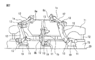
図2に、実施の形態における製造セルにて作業を行っているときの概略図を示す。図1および図2を参照して、本実施の形態の製造機械3a,3b,3cは、動作プログラムに基づいて自動的に溶接を行う溶接機械である。第1の製造機械3aは、第1のロボット1aと第1の溶接ガン8aとを含む。第2の製造機械3bは、第2のロボット1bと第2の溶接ガン8bとを含む。第3の製造機械3cは、第3のロボット1cと第3の溶接ガン8cとを含む。本実施の形態における作業の対象となる製品は、自動車の車体71である。本実施の形態では、車体71の複数の位置おいて、スポット溶接を行う作業を例に取りあげて説明する。
FIG. 2 shows a schematic diagram when work is performed in the manufacturing cell according to the embodiment. Referring to FIGS. 1 and 2,
車体71は、架台72に支持されている。架台72は、コンベヤ73により搬送されている。車体71は、予め定められた位置まで搬送して停止する。そして、ロボット1a,1b,1cが駆動して、複数の打点においてスポット溶接を行う。スポット溶接を行う打点の位置は、予め定められている。
The
本実施の形態におけるロボット1a,1b,1cは、隣り合うロボットが近接している。それぞれのロボットおよび溶接ガンは、隣接するロボットが行う作業の少なくとも一部を実施できるように形成されている。例えば、第1の製造機械3aが行う溶接の打点の一部は、第2の製造機械3bにて溶接を行うことができるように形成されている。また、同様に、第2の製造機械3bが行う溶接の打点の一部は、第1の製造機械3aにて溶接を行うことができるように形成されている。
The
このように、複数の製造機械3a,3b,3cは、作業を行うことができる作業可能範囲の少なくとも一部が重複している。製造機械3a,3b,3cは、隣接する製造機械の作業を実施できるように形成されている。
Thus, at least some of the workable ranges in which the plurality of
図3に、本実施の形態のセル制御装置および製造セルのブロック図を示す。図1から図3を参照して、第1の製造機械3aは、第1のロボット1aおよび第1の溶接ガン8aを制御する第1のロボット制御装置2aを備える。第1のロボット1aは、エンドエフェクタとしての第1の溶接ガン8aを支持している。本実施の形態の第1のロボット1aは、アーム12と複数の関節部13とを含む多関節ロボットである。
FIG. 3 shows a block diagram of the cell control device and the manufacturing cell of the present embodiment. 1 to 3, the
第1のロボット1aは、アーム12を駆動するアーム駆動装置を含む。アーム駆動装置は、アーム12の姿勢を変更するアーム駆動モータ14を含む。アーム駆動モータ14が駆動することにより、アーム12を関節部13にて所望の方向に向けることができる。第1のロボット1aは、アーム12を支持するベース部19と、ベース部19に対して回転する旋回部11とを備える。ベース部19は、設置面20に固定されている。旋回部11は、鉛直方向に延びる回転軸の周りに回転する。旋回部11が回転することにより、アーム12の向きを変更することができる。アーム駆動装置は、旋回部11を駆動する駆動モータを含む。
The
第1の溶接ガン8aは、先端のチップに通電することによりスポット溶接を行うことができるように形成されている。第1の溶接ガン8aは、チップを移動するガン駆動モータ18を含む。なお、エンドエフェクタとしては、溶接ガンに限られず、所望の作業に応じて任意の装置をロボットに連結することができる。
The
第1のロボット1aは、アーム12の移動を検出する状態検出器を備える。第1のロボット制御装置2aは、状態検出器の出力により、第1のロボット1aの位置および姿勢を検出する。本実施の形態における状態検出器は、アーム駆動モータ14に取り付けられた回転位置検出器15を含む。回転位置検出器15は、アーム駆動モータ14が駆動するときの回転位置を検出する。それぞれのアーム駆動モータ14の回転位置に基づいて、関節部13におけるアーム12の姿勢を検出することができる。また、状態検出器は、旋回部11を駆動する駆動モータに取り付けられた回転位置検出器を含む。旋回部11の回転位置に基づいて、アーム12が延びている方向を検出することができる。
The
第2のロボット1bおよび第3のロボット1cは、第1のロボット1aと同様の構成を有する。また、第2の溶接ガン8bおよび第3の溶接ガン8cは、第1の溶接ガン8aと同様の構成を有する。
The
第1のロボット制御装置2aは、バスを介して互いに接続されたCPU(Central Processing Unit)、RAM(Random Access Memory)、およびROM(Read Only Memory)等を有する演算処理装置を含む。第1のロボット制御装置2aは、予め作成された第1の動作プログラム9aに基づいて第1のロボット1aおよび第1の溶接ガン8aを駆動する。第1のロボット制御装置2aは、第1の動作プログラム9a等の任意の情報を記憶する記憶部24を含む。
The first
第1のロボット制御装置2aは、動作制御部21を含む。動作制御部21は、第1のロボット1aおよび第1の溶接ガン8aを駆動する動作指令を送出する。動作制御部21は、第1のロボット1aを駆動するための動作指令をアーム駆動部22に送出する。アーム駆動部22は、アーム駆動モータ14等のモータを駆動する電気回路を含む。アーム駆動部22は、動作指令に基づいてアーム駆動モータ14等に電気を供給して、アームを駆動する。また、動作制御部21は、第1の溶接ガン8aを駆動するための動作指令を溶接ガン駆動部23に送出する。溶接ガン駆動部23は、ガン駆動モータ18を駆動する電気回路やチップに電流を供給する電気回路を含む。溶接ガン駆動部23は、動作指令に基づいてガン駆動モータ18等に電気を供給する。
The first
第2の製造機械3bは、第2のロボット制御装置2bを含む。また、第3の製造機械3cは、第3のロボット制御装置2cを含む。第2のロボット制御装置2bおよび第3のロボット制御装置2cは、第1のロボット制御装置2aと同様の構成を有する。ロボット制御装置2a,2b,2cは、それぞれの製造機械を制御する機械制御装置として機能する。
The
第2のロボット制御装置2bには、予め作成された第2の動作プログラム9bが入力される。第3のロボット制御装置2cには、予め作成された第3の動作プログラム9cが入力される。それぞれのロボット1b,1cおよび溶接ガン8b,8cは、動作プログラム9b,9cに基づいて制御される。
A
本実施の形態におけるセル制御装置5および生産計画装置6は、CPUおよびRAM等を含む演算処理装置にて構成されている。セル制御装置5は、複数の製造機械3a,3b,3cの稼働情報を取得する稼働情報取得部51を含む。製造機械3a,3b,3cの稼働情報としては、それぞれのロボット1a,1b,1cの駆動の状態を示す変数および溶接ガン8a,8ab,8cの駆動の状態を示す変数が含まれる。
The
例えば、稼働情報には、駆動モータや溶接ガンのチップに供給される電流値、駆動モータに取り付けられた回転位置検出器15の出力、およびロボットや溶接ガンに取り付けられたセンサの出力等が含まれる。また、本実施の形態のアーム12を駆動する駆動モータは、フィードバック制御を実施している。稼働情報には、フィードバック制御等のロボット制御装置2a,2b,2cの内部の信号が含まれる。更に、稼働情報には、ロボット制御装置2a,2b,2cに入力される信号や出力される信号が含まれる。
For example, the operation information includes the current value supplied to the tip of the drive motor or welding gun, the output of the
稼働情報取得部51は、予め定められた時間間隔ごとに製造機械3a,3b,3cの稼働情報を取得する。セル制御装置5は、予め定められた情報を記憶する記憶部56を含む。記憶部56は、取得した稼働情報を記憶する。
The operation
セル制御装置5は、製造機械3a,3b,3cの稼働情報に基づいて、製造機械3a,3b,3cの部品の故障時期を予測する故障予測部52を含む。故障予測部52は、記憶部56に記憶された稼働情報に基づいて、将来に故障すると予測される部品および部品の故障時期を推定する。
The
例えば、ロボット1a,1b,1cは、アーム駆動モータ14が故障する場合がる。ここでは、故障する虞のある部品としてアーム駆動モータ14を例に取り上げて説明する。本実施の形態のロボット制御装置2a,2b,2cは、回転位置検出器15が出力する回転位置に基づいてアーム駆動モータ14のフィードバック制御を行っている。動作制御部21は、動作プログラムに基づいて速度指令を生成することができる。一方で、回転位置検出器15は、アーム駆動モータ14の実際の回転角を検出する。回転位置検出器15は、実際の回転角に基づいて実際の速度を算出することができる。そして、動作制御部21は、実施の速度に基づいて動作プログラムに基づく速度指令を修正することができる。
For example, in the
アーム駆動モータ14が故障すると、動作プログラムに基づく速度指令と実際の速度との差が大きくなる。このために、故障予測部52は、動作プログラムに基づく速度指令と実施の速度との差に基づいて、故障を予測することができる。
When the
例えば、セル制御装置5の記憶部56は、動作プログラムに基づく速度指令と実施の速度との速度差を予め定められた時間間隔ごとに記憶する。そして、記憶部56には、速度差の故障に関する判定値と、正常範囲の境界である許容値とが予め記憶されている。速度差が許容値を超えた場合に、故障予測部52は、過去のデータに基づいて速度差の上昇速度を算出する。故障予測部52は、上昇速度を用いて、速度差が判定値を超える時期を推定することができる。故障予測部52は、速度差が判定値を超える時期を、アーム駆動モータ14が故障する故障時期に設定することができる。なお、故障予測部52は、位置指令と回転位置検出器15により検出される実際の位置に基づいて、故障時期を推定しても構わない。
For example, the
また、他の故障時期の推定制御では、アーム駆動モータ14が故障すると生じるアーム駆動モータ14の振動を用いる。回転位置検出器15は、アーム駆動モータ14の回転位置に基づいて、振動を検出することができる。または、アーム駆動モータ14に、振動センサを取り付けても構わない。記憶部56は、アーム駆動モータ14の振動を予め定められた時間間隔ごとに記憶することができる。特に、記憶部56は、特定の周波数成分の振動の振幅を記憶することができる。故障が生じ始めると、特定の周波数成分の振幅が増加する。記憶部56には、特定の周波数成分の振幅の判定値が予め記憶されている。
In another failure time estimation control, vibration of the
故障予測部52は、特定の周波数成分の振動の振幅の上昇速度を、過去のデータに基づいて算出することができる。そして、故障予測部52は、特定の周波数成分の振動の振幅が判定値を超える時期を算出することができる。故障予測部52は、特定の周波数成分の振動の振幅が判定値を超える時期を故障時期として推定することができる。
The
このように、故障予測部52は、部品が故障した時に値が変化する変数について、変化速度を過去のデータに基づいて算出する。故障予測部52は、所定の変数の変化速度と予め定められた判定値に基づいて故障時期を予測することができる。
As described above, the
故障を予測する部品は、アーム駆動モータに限られず、製造装置を構成する任意の部品を選定することができる。故障を予測する部品は、予め選定されて記憶部に記憶しておくことができる。例えば、駆動する部分に取り付けられた減速機を、故障を推定する部品に選定することができる。なお、部品の故障を推定する制御は、この形態に限られず、故障予測部は、任意の方法にて故障時期を予測することができる。 The part that predicts the failure is not limited to the arm drive motor, and any part that constitutes the manufacturing apparatus can be selected. A part for which a failure is predicted can be selected in advance and stored in the storage unit. For example, a speed reducer attached to a portion to be driven can be selected as a part for estimating failure. Note that the control for estimating the failure of a component is not limited to this form, and the failure prediction unit can predict the failure time by any method.
故障予測部52は、製造機械3a,3b,3cの故障が予測される部品の名称や部品番号等の部品に関する情報を生産計画装置6に送信する。
The
本実施の形態における生産計画装置6は、故障が生じると予測された部品の情報に基づいて、自動的に製造機械の部品を発注する。たとえば、アーム駆動モータ14が故障すると予測される場合には、代替品となるアーム駆動モータを発注する。生産計画装置6は、部品の発注を行った際に、部品が製造セルの配置されている工場に到着する時期を取得する。すなわち、生産計画装置6は、故障が予測される部品の交換が可能な時期である交換時期を取得する。
The
なお、部品の発注および交換時期の取得は、この形態に限られず、生産計画装置6が出力する情報を作業者が判別し、作業者が部品を発注しても構わない。そして、作業者が部品の交換時期を取得して、生産計画装置6に入力しても構わない。
The ordering of parts and the acquisition of replacement time are not limited to this form, and the worker may determine the information output by the
セル制御装置5は、故障が予測される部品の交換時期を取得する交換時期取得部53を有する。交換時期取得部53は、生産計画装置6から交換時期を取得する。
The
セル制御装置5は、複数の製造機械3a,3b,3cの作業の負担の調整を行う作業調整部54を含む。本実施の形態では、製造機械3a,3b,3cに故障が予測されない場合には、複数の製造機械3a,3b,3cが同じ時刻に作業を開始して、ほぼ同じ時刻に作業が終了するように、打点の配分が設定されている。
The
作業調整部54は、推定した故障時期が交換時期よりも早いか否かを判別する。故障時期が交換時期以降である場合には、作業者は、製造機械が故障した時に、直ぐに部品を取り替えることができる。または、作業者は、故障が発生する前に部品を取り替えることができる。このために、製品の製造に大きな影響を与えずに、製造を継続することができる。
The
ところが、故障時期が交換時期よりも早い場合には、製造機械が故障すると製造機械が使えなくなる。作業調整部54は、故障時期が交換時期よりも早い場合に、部品の故障が予測された製造機械に対して、作業の負担が低減される制御を実施する。更に、作業調整部54は、部品の故障時期が交換時期よりも遅くなるように作業を設定する。
However, if the failure time is earlier than the replacement time, the production machine becomes unusable if the production machine fails. When the failure time is earlier than the replacement time, the
作業の負担を低減する方法については、予め定めておくことができる。たとえば、一部の作業を中止したり、ロボットの動作速度を低減したりする制御を行う。ロボットの動作速度を低減する制御は、故障が予測される製造機械において時間の余裕がある場合に好適である。次に、故障が予測される製造機械おいて、一部の作業を中止する制御を説明する。 A method for reducing the work burden can be determined in advance. For example, control is performed to stop part of the work or reduce the operation speed of the robot. Control for reducing the operation speed of the robot is suitable when there is a time margin in a production machine where a failure is predicted. Next, control for canceling a part of work in a manufacturing machine in which a failure is predicted will be described.
本実施の形態の製造セル4は、前述のように、互いに隣り合う製造機械3a,3b,3cの作業範囲が重複するように形成されている。すなわち、製造機械は、隣に配置されている製造機械が行う溶接の少なくとも一部の打点の溶接を行うことができるように形成されている。
As described above, the manufacturing cell 4 of the present embodiment is formed so that the work ranges of the
図2を参照して、本実施の形態では、第1のロボット1aの部品が故障すると予測された場合を例に取り上げて説明する。第1のロボット1aの部品が故障すると予測される場合には、第1の製造機械3aが行う複数の溶接の打点のうち一部の打点の作業を中止する。本実施の形態における作業調整部54は、第1の製造機械3aの溶接箇所の個数を減らす制御を実施する。作業を中止する打点は、第2の製造機械3bにて溶接が可能な打点である。
With reference to FIG. 2, in the present embodiment, a case where it is predicted that a component of the
記憶部56には、故障が予測される部品について、作業の負担の低減量と故障が進行する速度の低下量との関係が予め記憶されている。作業調整部54は、故障が進行する速度に応じて作業の負担の低減量を設定することができる。作業調整部54は、故障の進行する速度が大きいほど、作業の負担の低減量を大きくする制御を実施する。例えば、作業調整部54は、駆動モータの振動の振幅の上昇速度が大きいほど、打点の個数を多く低減する制御を実施することができる。
The
この場合に、作業調整部54は、故障時期が交換時期よりも遅くなるように、作業の負担の低減量を設定することができる。例えば、作業調整部54は、交換時期よりも遅い時期を設定する。作業調整部54は、設定した時期に故障するように、故障が進行する速度を算出する。作業調整部54は、算出した故障が進行する速度に基づいて、作業の負担の低減量を設定することができる。
In this case, the
作業調整部54は、部品の故障が予測された製造機械にて低減した作業を、他の製造機械が実施するように他の製造機械を制御する。作業調整部54は、故障が予測される部品を含む製造機械の一部の作業を、他の製造機械に移行する制御を実施する。例えば、作業調整部54は、第1の製造機械3aが中止した一部の打点の溶接作業を、第2の製造機械3bが実施するように制御する。
The
作業を移行する制御は、この形態に限られず、故障した部品や故障の種類に応じて、作業の負担の低減量を予め設定しておいても構わない。例えば、故障した部品に応じて第1の製造機械から第2の製造機械に移行する溶接の打点を予め定めておくことができる。この制御では、故障時期が交換時期よりも遅くなるように、多くの打点の作業を移行することが好ましい。 The control for shifting the work is not limited to this form, and a reduction amount of the work burden may be set in advance according to the failed part or the type of failure. For example, it is possible to determine in advance a welding point to be transferred from the first manufacturing machine to the second manufacturing machine in accordance with the failed part. In this control, it is preferable to shift the work of many hit points so that the failure time is later than the replacement time.
本実施の形態の作業調整部54は、動作プログラム生成部55を備える。本実施の形態における故障が予測される製造機械の作業の負担を低減する制御、および他の製造機械に作業を移行する制御は、動作プログラムを書き換えることにより実施することができる。
The
動作プログラム生成部55は、部品の故障が予測された製造機械の動作プログラムを作成する。また、動作プログラム生成部55は、作業を移行する他の製造機械の動作プログラムを作成する。そして、作業調整部54は、それぞれの製造機械の機械制御装置に動作プログラムを送出する。
The operation
例えば、第1のロボット1aの部品が故障すると予測される場合には、作業調整部54は、第1の製造機械3aが行う溶接の打点の個数が少なくなった第1の動作プログラムを第1のロボット制御装置2aに送出する。第1のロボット制御装置2aの記憶部24は、第1の動作プログラムを更新する。また、作業調整部54は、第2の製造機械3bが行う溶接の打点の個数が多くなった第2の動作プログラムを第2のロボット制御装置2bに送出する。第2のロボット制御装置2bの記憶部は、第2の動作プログラムを更新する。この制御により、複数の製造機械が行う作業を振り分けることができる。なお、故障が予測される製造機械の全ての作業を他の製造機械に移行しても構わない。
For example, when it is predicted that a component of the
故障が予測される製造機械の作業の一部または全部を他の製造機械に移行する制御としては、この形態に限られず、任意の制御を採用することができる。たとえば、それぞれのロボット制御装置が打点のパターンに応じた複数の動作プログラムを予め記憶していても構わない。作業調整部は、打点の位置をロボット制御装置に送出し、ロボット制御装置は、打点の位置に基づいて動作プログラムを選定することができる。 Control for transferring a part or all of the work of the manufacturing machine in which a failure is predicted to another manufacturing machine is not limited to this form, and arbitrary control can be adopted. For example, each robot control device may store in advance a plurality of operation programs corresponding to the dot pattern. The work adjustment unit sends the position of the hit point to the robot control device, and the robot control device can select an operation program based on the position of the hit point.
または、ロボット制御装置は、それぞれの打点に関する動作プログラムの要素を記憶しておくことができる。ロボット制御装置は、作業調整部から送出された打点の位置に基づいて、複数の動作プログラムの要素を組み合わせて、1つの動作プログラムを作成しても構わない。 Or the robot control apparatus can memorize | store the element of the operation program regarding each hit point. The robot control device may create one motion program by combining elements of a plurality of motion programs based on the positions of the hit points sent from the work adjustment unit.
図4に、本実施の形態における生産システムの制御のフローチャートを示す。ステップ91において、セル制御装置5の稼働情報取得部51は、それぞれの製造機械3a,3b,3cの稼働状態を取得する。
FIG. 4 shows a flowchart of the control of the production system in the present embodiment. In
ステップ92において、故障予測部52は、それぞれの製造機械3a,3b,3cの稼働状態を取得する。故障予測部52は、故障が予想される部品を検出する。故障予測部52は、部品の所定の変数に基づいて故障が予測されるか否かを判別することができる。例えば、駆動モータの振動の振幅が予め定められた許容値未満である場合には、故障予測部52は、駆動モータは正常であると判別することができる。故障予測部52は、駆動モータには故障が予測されないと判別することができる。
In
ステップ92において、故障が予測される部品が検出されない場合には、この制御を終了する。すなわち、全ての製造機械の部品が正常である場合には、この制御を終了する。ステップ92において、故障が予測される部品を検出した場合には、ステップ93に移行する。
In
ステップ93において、故障予測部52は、検出された部品の故障時期を推定する。故障予測部52は、生産計画装置6に故障が予想される部品の情報を送信する。生産計画装置6は、部品を発注するとともに部品が工場に納入される時期を取得する。すなわち、生産計画装置6は、工場において部品の交換が可能な交換時期を設定する。ステップ94において、交換時期取得部53は、交換時期を生産計画装置6から取得する。
In
次に、ステップ95において、作業調整部54は、故障時期が部品の交換時期よりも早いか否かを判別する。交換時期と故障時期とが同じである場合、または故障時期が交換時期よりも遅い場合には、この制御を終了する。故障時期が交換時期よりも早い場合には、ステップ96に移行する。
Next, in
ステップ96において、作業調整部54の動作プログラム生成部55は、それぞれの製造機械3a,3b,3cに対して、作業が変更された動作プログラムを作成する。動作プログラム生成部55は、故障が予測される部品を含む製造機械については、作業の負担が低減するように動作プログラムを作成する。また、動作プログラム生成部55は、低減された作業を追加するように他の製造機械の動作プログラムを作成する。動作プログラム生成部55は、対応する動作プログラムをロボット制御装置2a,2b,2cに送出する。
In
ステップ97において、ロボット制御装置2a,2b,2cは、それぞれの動作プログラムを更新する制御を行う。それぞれの製造機械3a,3b,3cは、更新された動作プログラムに基づいて作業を実施することができる。部品の交換が予測される製造機械の作業の負担を低減することができる。また、低減した作業は、他の製造機械にて実施することができる。このために、交換する部品の代替品が到着する前に製造装置が故障することを回避することができる。
In
本実施の形態の製造セルに含まれる複数の製造機械は、全てが溶接作業を行う製造機械である。すなわち、製造セルに含まれる製造機械が同一の作業を行うように形成されている。製造セルに含まれる製造機械としては、この形態に限られず、異なる作業を実施する製造機械が含まれていても構わない。 The plurality of manufacturing machines included in the manufacturing cell of the present embodiment are all manufacturing machines that perform welding operations. That is, the manufacturing machine included in the manufacturing cell is formed to perform the same operation. The manufacturing machine included in the manufacturing cell is not limited to this form, and a manufacturing machine that performs different operations may be included.
本実施の形態においては、製造機械として、溶接機械を例示して説明したが、この形態に限られず、任意の製造機械に本発明を適用することができる。例えば、製造機械としては、ワークの搬送を行う搬送機械、塗装を行う塗装機械、および印刷を行う印刷機等を例示することができる。更に、製造機械としては工作機械を例示することができる。製造セルは、複数の工作機械にて材料を切削することにより、予め定められた製品を製造することができる。そして、1つの工作機械の作業の少なくとも一部を他の工作機械にて実施できる場合に本発明を適用することができる。 In the present embodiment, a welding machine has been described as an example of a manufacturing machine. However, the present invention is not limited to this form, and the present invention can be applied to any manufacturing machine. For example, examples of the manufacturing machine include a transport machine that transports a workpiece, a coating machine that performs coating, and a printing machine that performs printing. Furthermore, a machine tool can be illustrated as a manufacturing machine. The manufacturing cell can manufacture a predetermined product by cutting material with a plurality of machine tools. The present invention can be applied when at least a part of the work of one machine tool can be performed by another machine tool.
上述の制御においては、機能および作用が変更されない範囲において適宜ステップの順序を変更することができる。 In the above control, the order of the steps can be changed as appropriate within a range in which the function and the action are not changed.
上記の実施の形態は、適宜組み合わせることができる。上述のそれぞれの図において、同一または相等する部分には同一の符号を付している。なお、上記の実施の形態は例示であり発明を限定するものではない。また、実施の形態においては、特許請求の範囲に示される実施の形態の変更が含まれている。 The above embodiments can be combined as appropriate. In the respective drawings described above, the same or equivalent parts are denoted by the same reference numerals. In addition, said embodiment is an illustration and does not limit invention. Further, in the embodiment, changes of the embodiment shown in the claims are included.
1a,1b,1c ロボット
2a,2b,2c ロボット制御装置
3a,3b,3c 製造機械
4 製造セル
5 セル制御装置
6 生産計画装置
8a,8b,8c 溶接ガン
9a,9b,9c 動作プログラム
15 回転位置検出器
21 動作制御部
24 記憶部
51 稼働情報取得部
52 故障予測部
53 交換時期取得部
54 作業調整部
55 動作プログラム生成部
56 記憶部
1a, 1b,
Claims (3)
製造機械の稼働情報を取得する稼働情報取得部と、
製造機械の稼働情報に基づいて製造機械の部品の故障時期を予測し、製造機械の部品の管理を行う部品管理装置に故障が予測される部品の情報を送信する故障予測部と、
前記部品の交換が可能な時期である交換時期を部品管理装置から取得する交換時期取得部と、
前記故障時期が前記交換時期よりも早いか否かを判別し、前記故障時期が前記交換時期よりも早い場合に、前記故障時期が前記交換時期よりも遅くなるように、前記部品の故障が予測された製造機械の作業の一部を減らして稼働を継続する制御と、減らした前記作業を他の製造機械に実施させる制御とを実施する作業調整部と、を備えることを特徴とする、セル制御装置。 A cell control device for controlling a manufacturing cell including a plurality of manufacturing machines,
An operation information acquisition unit that acquires operation information of the manufacturing machine;
A failure prediction unit that predicts a failure time of a part of the manufacturing machine based on operation information of the manufacturing machine, and transmits information on a part that is predicted to fail to a parts management device that manages the part of the manufacturing machine;
A replacement time acquisition unit that acquires a replacement time, which is a time when the parts can be replaced, from the part management device;
It is determined whether or not the failure time is earlier than the replacement time, and when the failure time is earlier than the replacement time, the failure of the component is predicted so that the failure time is later than the replacement time. A cell comprising: a control for reducing a part of the work of the manufactured manufacturing machine and continuing the operation; and a work adjusting unit for executing a control for causing the other manufacturing machine to perform the reduced work. Control device.
複数の製造機械を含む製造セルと、
製造機械の部品の管理を行う部品管理装置とを備え、
セル制御装置は、部品管理装置にネットワークを介して故障が予測される部品の情報を送信し、部品管理装置から交換時期を取得することを特徴とする、生産システム。 A cell control device according to claim 1;
A production cell comprising a plurality of production machines;
A parts management device for managing parts of the manufacturing machine,
The cell control device transmits information on a component that is predicted to fail via a network to the component management device, and acquires a replacement time from the component management device.
Priority Applications (4)
| Application Number | Priority Date | Filing Date | Title |
|---|---|---|---|
| JP2015233408A JP6285403B2 (en) | 2015-11-30 | 2015-11-30 | Cell control device and production system for predicting failure of manufacturing machine |
| DE102016013993.5A DE102016013993B4 (en) | 2015-11-30 | 2016-11-23 | CELL CONTROL DEVICE FOREDICATING A FAILURE OF MANUFACTURING MACHINES AND MANUFACTURING SYSTEM |
| US15/363,214 US10274931B2 (en) | 2015-11-30 | 2016-11-29 | Cell control apparatus which predicts failure of manufacturing machines and production system |
| CN201611076608.8A CN106814715B (en) | 2015-11-30 | 2016-11-29 | The unit control apparatus and production system of prediction manufacture mechanical breakdown |
Applications Claiming Priority (1)
| Application Number | Priority Date | Filing Date | Title |
|---|---|---|---|
| JP2015233408A JP6285403B2 (en) | 2015-11-30 | 2015-11-30 | Cell control device and production system for predicting failure of manufacturing machine |
Publications (2)
| Publication Number | Publication Date |
|---|---|
| JP2017102554A JP2017102554A (en) | 2017-06-08 |
| JP6285403B2 true JP6285403B2 (en) | 2018-02-28 |
Family
ID=58693246
Family Applications (1)
| Application Number | Title | Priority Date | Filing Date |
|---|---|---|---|
| JP2015233408A Active JP6285403B2 (en) | 2015-11-30 | 2015-11-30 | Cell control device and production system for predicting failure of manufacturing machine |
Country Status (4)
| Country | Link |
|---|---|
| US (1) | US10274931B2 (en) |
| JP (1) | JP6285403B2 (en) |
| CN (1) | CN106814715B (en) |
| DE (1) | DE102016013993B4 (en) |
Families Citing this family (19)
| Publication number | Priority date | Publication date | Assignee | Title |
|---|---|---|---|---|
| CN108885969B (en) * | 2016-03-14 | 2023-08-15 | 株式会社国际电气 | Substrate processing apparatus, controller, and recording medium |
| JP6718415B2 (en) * | 2017-06-26 | 2020-07-08 | 株式会社日立ビルシステム | Parts replacement prediction device, parts replacement prediction system, parts replacement prediction method |
| JP7043801B2 (en) * | 2017-11-15 | 2022-03-30 | トヨタ自動車株式会社 | Abnormality sign notification system, abnormality sign notification method and program |
| JP7125225B2 (en) * | 2017-11-24 | 2022-08-24 | トヨタ自動車株式会社 | Abnormality predictor notification system, method, and program |
| JP7187759B2 (en) * | 2018-03-29 | 2022-12-13 | 株式会社東京精密 | Measuring machine management device and method |
| US11016468B1 (en) * | 2018-06-12 | 2021-05-25 | Ricky Dale Barker | Monitoring system for use in industrial operations |
| WO2019239527A1 (en) * | 2018-06-13 | 2019-12-19 | 日産自動車株式会社 | Maintenance management device and maintenance management method |
| JP7151269B2 (en) | 2018-08-23 | 2022-10-12 | セイコーエプソン株式会社 | Robot control device and control method |
| FI20180097A1 (en) * | 2018-08-29 | 2020-03-01 | Ponsse Oyj | Determining a condition of a structural part of a working machine |
| JP7373272B2 (en) | 2018-09-13 | 2023-11-02 | ナブテスコ株式会社 | Gear reducers, oil seals with encoders, industrial machinery and factories |
| JP7107144B2 (en) | 2018-09-28 | 2022-07-27 | セイコーエプソン株式会社 | Production system and method |
| US11110606B2 (en) * | 2019-01-02 | 2021-09-07 | The Boeing Company | Coordinating work within a multi-robot cell |
| CN109732602B (en) * | 2019-01-08 | 2021-03-16 | 英华达(上海)科技有限公司 | Mechanical arm speed regulation method, system, equipment and medium |
| WO2020176069A1 (en) * | 2019-02-25 | 2020-09-03 | Halliburton Energy Services, Inc. | Trajectory based maintenance |
| JP7255353B2 (en) | 2019-05-22 | 2023-04-11 | セイコーエプソン株式会社 | Robot control device and control method |
| JP2021033566A (en) * | 2019-08-22 | 2021-03-01 | パナソニックIpマネジメント株式会社 | Line control system and work command determination method |
| JP2022086500A (en) * | 2020-11-30 | 2022-06-09 | パナソニックIpマネジメント株式会社 | Learning device, learning method, and failure prediction system |
| DE112021007399T5 (en) | 2021-06-04 | 2024-01-18 | Fanuc Corporation | Maintenance planning device and maintenance planning method |
| JP2024034523A (en) * | 2022-08-31 | 2024-03-13 | 株式会社日立製作所 | Automatic work line control device and its control method |
Family Cites Families (11)
| Publication number | Priority date | Publication date | Assignee | Title |
|---|---|---|---|---|
| JP3530263B2 (en) | 1995-04-17 | 2004-05-24 | 新日本製鐵株式会社 | Work replacement method for broken robot |
| JP2004202624A (en) | 2002-12-25 | 2004-07-22 | Kawasaki Heavy Ind Ltd | Method and apparatus for using and integrating robot information |
| JP2004334509A (en) * | 2003-05-07 | 2004-11-25 | Mitsubishi Electric Corp | Production management system |
| JP2005258585A (en) * | 2004-03-09 | 2005-09-22 | Sumitomo Heavy Ind Ltd | Molding machine part automatic ordering method, system, and program |
| US7467841B2 (en) | 2006-09-07 | 2008-12-23 | Kabushiki Kaisha Toshiba | Maintenance scheduling system, maintenance scheduling method and image forming apparatus |
| EP1965281A1 (en) * | 2007-03-02 | 2008-09-03 | Abb Research Ltd. | Dynamic maintenance plan for an industrial robot |
| JP2009237714A (en) * | 2008-03-26 | 2009-10-15 | Seiko Epson Corp | Work device system |
| EP2421130A1 (en) * | 2010-08-20 | 2012-02-22 | Siemens Aktiengesellschaft | Method and sensor unit for determining the current usage level indicator value of an electric and/or electronic component in a wind turbine |
| JP6664893B2 (en) * | 2014-12-19 | 2020-03-13 | 川崎重工業株式会社 | Robot maintenance support device and method |
| US9921760B2 (en) * | 2015-10-22 | 2018-03-20 | International Business Machines Corporation | Shifting wearout of storage disks |
| US20180284758A1 (en) * | 2016-05-09 | 2018-10-04 | StrongForce IoT Portfolio 2016, LLC | Methods and systems for industrial internet of things data collection for equipment analysis in an upstream oil and gas environment |
-
2015
- 2015-11-30 JP JP2015233408A patent/JP6285403B2/en active Active
-
2016
- 2016-11-23 DE DE102016013993.5A patent/DE102016013993B4/en active Active
- 2016-11-29 CN CN201611076608.8A patent/CN106814715B/en active Active
- 2016-11-29 US US15/363,214 patent/US10274931B2/en active Active
Also Published As
| Publication number | Publication date |
|---|---|
| DE102016013993B4 (en) | 2020-09-24 |
| CN106814715A (en) | 2017-06-09 |
| CN106814715B (en) | 2019-01-25 |
| JP2017102554A (en) | 2017-06-08 |
| US10274931B2 (en) | 2019-04-30 |
| DE102016013993A1 (en) | 2017-06-01 |
| US20170153625A1 (en) | 2017-06-01 |
Similar Documents
| Publication | Publication Date | Title |
|---|---|---|
| JP6285403B2 (en) | Cell control device and production system for predicting failure of manufacturing machine | |
| TWI623398B (en) | Robot system | |
| CN101947789B (en) | Method and device for operating a manipulator | |
| JP6469069B2 (en) | Robot control apparatus and robot control method having function for facilitating learning | |
| JP6444943B2 (en) | Manufacturing management device for controlling a manufacturing cell for performing maintenance work | |
| US10379531B2 (en) | Test system for performing machine test | |
| JP2018069410A (en) | Robot control device having learning control function | |
| EP3351355B1 (en) | Device and method for positioning processing tool | |
| CN110722552A (en) | Automatic route generation device | |
| JP2016087706A (en) | Processing device, teaching method, workpiece production method, controller and control method | |
| CN110154043B (en) | Robot system for learning control based on machining result and control method thereof | |
| JP2019104097A (en) | Robot system | |
| JP6858521B2 (en) | Robot recovery support device and robot system equipped with it | |
| US20070225834A1 (en) | Method and Means for Using a Control File With a Control Unit of a Machine | |
| JP2017228218A (en) | Cell production system for manufacturing cell to autonomously manufacture | |
| JP6618656B1 (en) | Maintenance support system, numerical control device, and maintenance support system control method | |
| JP7107144B2 (en) | Production system and method | |
| JP4682907B2 (en) | Motor control device | |
| JP2021020290A (en) | Prediction device | |
| JP2772230B2 (en) | Offline teaching device | |
| JP2020030673A (en) | Robot controller and method for controlling the same | |
| KR101138019B1 (en) | Control Method And Apparatus For Robot | |
| CN111367235B (en) | Diagnostic maintenance system of numerical control machine tool | |
| JP2006021268A (en) | Service life time predicting method of robot, operation pattern making method of robot and their program | |
| JP2004268098A (en) | Welding method, welding control device, and welding system |
Legal Events
| Date | Code | Title | Description |
|---|---|---|---|
| A977 | Report on retrieval |
Free format text: JAPANESE INTERMEDIATE CODE: A971007 Effective date: 20170912 |
|
| A131 | Notification of reasons for refusal |
Free format text: JAPANESE INTERMEDIATE CODE: A131 Effective date: 20170926 |
|
| A521 | Request for written amendment filed |
Free format text: JAPANESE INTERMEDIATE CODE: A523 Effective date: 20171025 |
|
| TRDD | Decision of grant or rejection written | ||
| A01 | Written decision to grant a patent or to grant a registration (utility model) |
Free format text: JAPANESE INTERMEDIATE CODE: A01 Effective date: 20180109 |
|
| A61 | First payment of annual fees (during grant procedure) |
Free format text: JAPANESE INTERMEDIATE CODE: A61 Effective date: 20180201 |
|
| R150 | Certificate of patent or registration of utility model |
Ref document number: 6285403 Country of ref document: JP Free format text: JAPANESE INTERMEDIATE CODE: R150 |