JP6283487B2 - Method for producing non-aqueous electrolyte secondary battery - Google Patents
Method for producing non-aqueous electrolyte secondary battery Download PDFInfo
- Publication number
- JP6283487B2 JP6283487B2 JP2013202446A JP2013202446A JP6283487B2 JP 6283487 B2 JP6283487 B2 JP 6283487B2 JP 2013202446 A JP2013202446 A JP 2013202446A JP 2013202446 A JP2013202446 A JP 2013202446A JP 6283487 B2 JP6283487 B2 JP 6283487B2
- Authority
- JP
- Japan
- Prior art keywords
- electrolyte
- power generation
- generation element
- negative electrode
- additive
- Prior art date
- Legal status (The legal status is an assumption and is not a legal conclusion. Google has not performed a legal analysis and makes no representation as to the accuracy of the status listed.)
- Active
Links
- 239000011255 nonaqueous electrolyte Substances 0.000 title claims description 22
- 238000004519 manufacturing process Methods 0.000 title claims description 11
- 239000003792 electrolyte Substances 0.000 claims description 53
- 238000010248 power generation Methods 0.000 claims description 48
- 239000000654 additive Substances 0.000 claims description 39
- 230000000996 additive effect Effects 0.000 claims description 36
- 239000007773 negative electrode material Substances 0.000 claims description 24
- 230000002829 reductive effect Effects 0.000 claims description 14
- 239000002000 Electrolyte additive Substances 0.000 claims description 12
- 238000000034 method Methods 0.000 claims description 10
- 230000008569 process Effects 0.000 claims description 9
- 238000000354 decomposition reaction Methods 0.000 claims description 8
- 239000011148 porous material Substances 0.000 claims description 6
- 238000010030 laminating Methods 0.000 claims description 5
- 239000008151 electrolyte solution Substances 0.000 claims description 3
- 239000007788 liquid Substances 0.000 claims description 3
- 239000010410 layer Substances 0.000 description 40
- 239000005001 laminate film Substances 0.000 description 16
- -1 polytetrafluoroethylene Polymers 0.000 description 13
- OKTJSMMVPCPJKN-UHFFFAOYSA-N Carbon Chemical compound [C] OKTJSMMVPCPJKN-UHFFFAOYSA-N 0.000 description 11
- 229910052751 metal Inorganic materials 0.000 description 11
- 239000002184 metal Substances 0.000 description 11
- 238000003825 pressing Methods 0.000 description 9
- 239000007774 positive electrode material Substances 0.000 description 8
- 239000011149 active material Substances 0.000 description 7
- 239000011230 binding agent Substances 0.000 description 7
- 239000011888 foil Substances 0.000 description 7
- 229910052744 lithium Inorganic materials 0.000 description 7
- 230000002093 peripheral effect Effects 0.000 description 7
- WHXSMMKQMYFTQS-UHFFFAOYSA-N Lithium Chemical compound [Li] WHXSMMKQMYFTQS-UHFFFAOYSA-N 0.000 description 6
- SECXISVLQFMRJM-UHFFFAOYSA-N N-Methylpyrrolidone Chemical compound CN1CCCC1=O SECXISVLQFMRJM-UHFFFAOYSA-N 0.000 description 6
- 239000004743 Polypropylene Substances 0.000 description 6
- 230000000694 effects Effects 0.000 description 6
- 239000010439 graphite Substances 0.000 description 6
- 229910002804 graphite Inorganic materials 0.000 description 6
- 229920000098 polyolefin Polymers 0.000 description 6
- 229920001155 polypropylene Polymers 0.000 description 6
- 229920003002 synthetic resin Polymers 0.000 description 6
- 239000000057 synthetic resin Substances 0.000 description 6
- VAYTZRYEBVHVLE-UHFFFAOYSA-N 1,3-dioxol-2-one Chemical compound O=C1OC=CO1 VAYTZRYEBVHVLE-UHFFFAOYSA-N 0.000 description 5
- PXHVJJICTQNCMI-UHFFFAOYSA-N Nickel Chemical compound [Ni] PXHVJJICTQNCMI-UHFFFAOYSA-N 0.000 description 5
- HBBGRARXTFLTSG-UHFFFAOYSA-N Lithium ion Chemical compound [Li+] HBBGRARXTFLTSG-UHFFFAOYSA-N 0.000 description 4
- 239000004698 Polyethylene Substances 0.000 description 4
- 229910052782 aluminium Inorganic materials 0.000 description 4
- 239000006229 carbon black Substances 0.000 description 4
- 239000002131 composite material Substances 0.000 description 4
- 229910001416 lithium ion Inorganic materials 0.000 description 4
- 229910003002 lithium salt Inorganic materials 0.000 description 4
- 159000000002 lithium salts Chemical class 0.000 description 4
- 230000014759 maintenance of location Effects 0.000 description 4
- 239000011572 manganese Substances 0.000 description 4
- 239000002245 particle Substances 0.000 description 4
- 229920000573 polyethylene Polymers 0.000 description 4
- 229920005989 resin Polymers 0.000 description 4
- 239000011347 resin Substances 0.000 description 4
- 239000002002 slurry Substances 0.000 description 4
- 239000011800 void material Substances 0.000 description 4
- BJWMSGRKJIOCNR-UHFFFAOYSA-N 4-ethenyl-1,3-dioxolan-2-one Chemical compound C=CC1COC(=O)O1 BJWMSGRKJIOCNR-UHFFFAOYSA-N 0.000 description 3
- 229920002134 Carboxymethyl cellulose Polymers 0.000 description 3
- RYGMFSIKBFXOCR-UHFFFAOYSA-N Copper Chemical compound [Cu] RYGMFSIKBFXOCR-UHFFFAOYSA-N 0.000 description 3
- 239000002033 PVDF binder Substances 0.000 description 3
- XAGFODPZIPBFFR-UHFFFAOYSA-N aluminium Chemical compound [Al] XAGFODPZIPBFFR-UHFFFAOYSA-N 0.000 description 3
- 229910003481 amorphous carbon Inorganic materials 0.000 description 3
- 239000003575 carbonaceous material Substances 0.000 description 3
- 239000001768 carboxy methyl cellulose Substances 0.000 description 3
- 235000010948 carboxy methyl cellulose Nutrition 0.000 description 3
- 239000008112 carboxymethyl-cellulose Substances 0.000 description 3
- 230000000052 comparative effect Effects 0.000 description 3
- 239000011889 copper foil Substances 0.000 description 3
- 229910052748 manganese Inorganic materials 0.000 description 3
- 229910052759 nickel Inorganic materials 0.000 description 3
- 229920002981 polyvinylidene fluoride Polymers 0.000 description 3
- 239000002904 solvent Substances 0.000 description 3
- 239000010935 stainless steel Substances 0.000 description 3
- 229910001220 stainless steel Inorganic materials 0.000 description 3
- 238000003860 storage Methods 0.000 description 3
- 229920003048 styrene butadiene rubber Polymers 0.000 description 3
- HBJICDATLIMQTJ-UHFFFAOYSA-N C(O)(O)=O.C(=C)C=CC=C Chemical compound C(O)(O)=O.C(=C)C=CC=C HBJICDATLIMQTJ-UHFFFAOYSA-N 0.000 description 2
- OIFBSDVPJOWBCH-UHFFFAOYSA-N Diethyl carbonate Chemical compound CCOC(=O)OCC OIFBSDVPJOWBCH-UHFFFAOYSA-N 0.000 description 2
- KMTRUDSVKNLOMY-UHFFFAOYSA-N Ethylene carbonate Chemical compound O=C1OCCO1 KMTRUDSVKNLOMY-UHFFFAOYSA-N 0.000 description 2
- CPLXHLVBOLITMK-UHFFFAOYSA-N Magnesium oxide Chemical compound [Mg]=O CPLXHLVBOLITMK-UHFFFAOYSA-N 0.000 description 2
- VYPSYNLAJGMNEJ-UHFFFAOYSA-N Silicium dioxide Chemical compound O=[Si]=O VYPSYNLAJGMNEJ-UHFFFAOYSA-N 0.000 description 2
- GWEVSGVZZGPLCZ-UHFFFAOYSA-N Titan oxide Chemical compound O=[Ti]=O GWEVSGVZZGPLCZ-UHFFFAOYSA-N 0.000 description 2
- MCMNRKCIXSYSNV-UHFFFAOYSA-N Zirconium dioxide Chemical compound O=[Zr]=O MCMNRKCIXSYSNV-UHFFFAOYSA-N 0.000 description 2
- 239000006230 acetylene black Substances 0.000 description 2
- 229910052799 carbon Inorganic materials 0.000 description 2
- 239000003795 chemical substances by application Substances 0.000 description 2
- 239000002482 conductive additive Substances 0.000 description 2
- 125000004122 cyclic group Chemical group 0.000 description 2
- QHGJSLXSVXVKHZ-UHFFFAOYSA-N dilithium;dioxido(dioxo)manganese Chemical compound [Li+].[Li+].[O-][Mn]([O-])(=O)=O QHGJSLXSVXVKHZ-UHFFFAOYSA-N 0.000 description 2
- 230000004927 fusion Effects 0.000 description 2
- 230000006872 improvement Effects 0.000 description 2
- 239000010954 inorganic particle Substances 0.000 description 2
- XEEYBQQBJWHFJM-UHFFFAOYSA-N iron Substances [Fe] XEEYBQQBJWHFJM-UHFFFAOYSA-N 0.000 description 2
- 238000005304 joining Methods 0.000 description 2
- 239000000203 mixture Substances 0.000 description 2
- 238000012986 modification Methods 0.000 description 2
- 230000004048 modification Effects 0.000 description 2
- 239000003960 organic solvent Substances 0.000 description 2
- 229920000139 polyethylene terephthalate Polymers 0.000 description 2
- 239000005020 polyethylene terephthalate Substances 0.000 description 2
- 239000004810 polytetrafluoroethylene Substances 0.000 description 2
- 229920001343 polytetrafluoroethylene Polymers 0.000 description 2
- 239000000843 powder Substances 0.000 description 2
- 229910052596 spinel Inorganic materials 0.000 description 2
- 239000011029 spinel Substances 0.000 description 2
- FSSPGSAQUIYDCN-UHFFFAOYSA-N 1,3-Propane sultone Chemical group O=S1(=O)CCCO1 FSSPGSAQUIYDCN-UHFFFAOYSA-N 0.000 description 1
- SBLRHMKNNHXPHG-UHFFFAOYSA-N 4-fluoro-1,3-dioxolan-2-one Chemical compound FC1COC(=O)O1 SBLRHMKNNHXPHG-UHFFFAOYSA-N 0.000 description 1
- 229910000838 Al alloy Inorganic materials 0.000 description 1
- 229910013063 LiBF 4 Inorganic materials 0.000 description 1
- 229910013372 LiC 4 Inorganic materials 0.000 description 1
- 229910012851 LiCoO 2 Inorganic materials 0.000 description 1
- 229910015643 LiMn 2 O 4 Inorganic materials 0.000 description 1
- 229910014689 LiMnO Inorganic materials 0.000 description 1
- 229910013290 LiNiO 2 Inorganic materials 0.000 description 1
- 229910013870 LiPF 6 Inorganic materials 0.000 description 1
- 229910001290 LiPF6 Inorganic materials 0.000 description 1
- PWHULOQIROXLJO-UHFFFAOYSA-N Manganese Chemical compound [Mn] PWHULOQIROXLJO-UHFFFAOYSA-N 0.000 description 1
- PNEYBMLMFCGWSK-UHFFFAOYSA-N aluminium oxide Inorganic materials [O-2].[O-2].[O-2].[Al+3].[Al+3] PNEYBMLMFCGWSK-UHFFFAOYSA-N 0.000 description 1
- 239000007864 aqueous solution Substances 0.000 description 1
- 229910052796 boron Inorganic materials 0.000 description 1
- 150000004649 carbonic acid derivatives Chemical class 0.000 description 1
- 239000000919 ceramic Substances 0.000 description 1
- 230000008859 change Effects 0.000 description 1
- 229910052804 chromium Inorganic materials 0.000 description 1
- 229910017052 cobalt Inorganic materials 0.000 description 1
- 239000010941 cobalt Substances 0.000 description 1
- GUTLYIVDDKVIGB-UHFFFAOYSA-N cobalt atom Chemical compound [Co] GUTLYIVDDKVIGB-UHFFFAOYSA-N 0.000 description 1
- 150000001875 compounds Chemical class 0.000 description 1
- IEJIGPNLZYLLBP-UHFFFAOYSA-N dimethyl carbonate Chemical compound COC(=O)OC IEJIGPNLZYLLBP-UHFFFAOYSA-N 0.000 description 1
- 238000007599 discharging Methods 0.000 description 1
- JBTWLSYIZRCDFO-UHFFFAOYSA-N ethyl methyl carbonate Chemical compound CCOC(=O)OC JBTWLSYIZRCDFO-UHFFFAOYSA-N 0.000 description 1
- 238000011156 evaluation Methods 0.000 description 1
- 239000004744 fabric Substances 0.000 description 1
- 125000001153 fluoro group Chemical group F* 0.000 description 1
- 239000011521 glass Substances 0.000 description 1
- 229910021469 graphitizable carbon Inorganic materials 0.000 description 1
- 229920006015 heat resistant resin Polymers 0.000 description 1
- 239000012793 heat-sealing layer Substances 0.000 description 1
- 125000004435 hydrogen atom Chemical group [H]* 0.000 description 1
- 238000002347 injection Methods 0.000 description 1
- 239000007924 injection Substances 0.000 description 1
- 229910052742 iron Inorganic materials 0.000 description 1
- 229910052749 magnesium Inorganic materials 0.000 description 1
- 239000000395 magnesium oxide Substances 0.000 description 1
- 239000000463 material Substances 0.000 description 1
- 230000007246 mechanism Effects 0.000 description 1
- 239000012528 membrane Substances 0.000 description 1
- 239000012982 microporous membrane Substances 0.000 description 1
- 239000012046 mixed solvent Substances 0.000 description 1
- 229910021382 natural graphite Inorganic materials 0.000 description 1
- 229910021470 non-graphitizable carbon Inorganic materials 0.000 description 1
- 239000004745 nonwoven fabric Substances 0.000 description 1
- 239000002861 polymer material Substances 0.000 description 1
- RUOJZAUFBMNUDX-UHFFFAOYSA-N propylene carbonate Chemical compound CC1COC(=O)O1 RUOJZAUFBMNUDX-UHFFFAOYSA-N 0.000 description 1
- 239000011241 protective layer Substances 0.000 description 1
- 230000000717 retained effect Effects 0.000 description 1
- 239000000377 silicon dioxide Substances 0.000 description 1
- 229920002379 silicone rubber Polymers 0.000 description 1
- 239000002356 single layer Substances 0.000 description 1
- 239000007787 solid Substances 0.000 description 1
- BDHFUVZGWQCTTF-UHFFFAOYSA-M sulfonate Chemical compound [O-]S(=O)=O BDHFUVZGWQCTTF-UHFFFAOYSA-M 0.000 description 1
- 150000008053 sultones Chemical class 0.000 description 1
- 229910052719 titanium Inorganic materials 0.000 description 1
- 229910052723 transition metal Inorganic materials 0.000 description 1
- 150000003624 transition metals Chemical class 0.000 description 1
- 229910052721 tungsten Inorganic materials 0.000 description 1
- 229910052720 vanadium Inorganic materials 0.000 description 1
- XLYOFNOQVPJJNP-UHFFFAOYSA-N water Substances O XLYOFNOQVPJJNP-UHFFFAOYSA-N 0.000 description 1
- 238000004804 winding Methods 0.000 description 1
Images


Classifications
-
- H—ELECTRICITY
- H01—ELECTRIC ELEMENTS
- H01M—PROCESSES OR MEANS, e.g. BATTERIES, FOR THE DIRECT CONVERSION OF CHEMICAL ENERGY INTO ELECTRICAL ENERGY
- H01M10/00—Secondary cells; Manufacture thereof
- H01M10/42—Methods or arrangements for servicing or maintenance of secondary cells or secondary half-cells
- H01M10/4235—Safety or regulating additives or arrangements in electrodes, separators or electrolyte
-
- H—ELECTRICITY
- H01—ELECTRIC ELEMENTS
- H01M—PROCESSES OR MEANS, e.g. BATTERIES, FOR THE DIRECT CONVERSION OF CHEMICAL ENERGY INTO ELECTRICAL ENERGY
- H01M10/00—Secondary cells; Manufacture thereof
- H01M10/05—Accumulators with non-aqueous electrolyte
- H01M10/052—Li-accumulators
- H01M10/0525—Rocking-chair batteries, i.e. batteries with lithium insertion or intercalation in both electrodes; Lithium-ion batteries
-
- H—ELECTRICITY
- H01—ELECTRIC ELEMENTS
- H01M—PROCESSES OR MEANS, e.g. BATTERIES, FOR THE DIRECT CONVERSION OF CHEMICAL ENERGY INTO ELECTRICAL ENERGY
- H01M10/00—Secondary cells; Manufacture thereof
- H01M10/05—Accumulators with non-aqueous electrolyte
- H01M10/056—Accumulators with non-aqueous electrolyte characterised by the materials used as electrolytes, e.g. mixed inorganic/organic electrolytes
- H01M10/0564—Accumulators with non-aqueous electrolyte characterised by the materials used as electrolytes, e.g. mixed inorganic/organic electrolytes the electrolyte being constituted of organic materials only
- H01M10/0566—Liquid materials
- H01M10/0567—Liquid materials characterised by the additives
-
- H—ELECTRICITY
- H01—ELECTRIC ELEMENTS
- H01M—PROCESSES OR MEANS, e.g. BATTERIES, FOR THE DIRECT CONVERSION OF CHEMICAL ENERGY INTO ELECTRICAL ENERGY
- H01M10/00—Secondary cells; Manufacture thereof
- H01M10/05—Accumulators with non-aqueous electrolyte
- H01M10/058—Construction or manufacture
- H01M10/0585—Construction or manufacture of accumulators having only flat construction elements, i.e. flat positive electrodes, flat negative electrodes and flat separators
-
- H—ELECTRICITY
- H01—ELECTRIC ELEMENTS
- H01M—PROCESSES OR MEANS, e.g. BATTERIES, FOR THE DIRECT CONVERSION OF CHEMICAL ENERGY INTO ELECTRICAL ENERGY
- H01M10/00—Secondary cells; Manufacture thereof
- H01M10/42—Methods or arrangements for servicing or maintenance of secondary cells or secondary half-cells
- H01M10/44—Methods for charging or discharging
- H01M10/446—Initial charging measures
-
- Y—GENERAL TAGGING OF NEW TECHNOLOGICAL DEVELOPMENTS; GENERAL TAGGING OF CROSS-SECTIONAL TECHNOLOGIES SPANNING OVER SEVERAL SECTIONS OF THE IPC; TECHNICAL SUBJECTS COVERED BY FORMER USPC CROSS-REFERENCE ART COLLECTIONS [XRACs] AND DIGESTS
- Y02—TECHNOLOGIES OR APPLICATIONS FOR MITIGATION OR ADAPTATION AGAINST CLIMATE CHANGE
- Y02E—REDUCTION OF GREENHOUSE GAS [GHG] EMISSIONS, RELATED TO ENERGY GENERATION, TRANSMISSION OR DISTRIBUTION
- Y02E60/00—Enabling technologies; Technologies with a potential or indirect contribution to GHG emissions mitigation
- Y02E60/10—Energy storage using batteries
-
- Y—GENERAL TAGGING OF NEW TECHNOLOGICAL DEVELOPMENTS; GENERAL TAGGING OF CROSS-SECTIONAL TECHNOLOGIES SPANNING OVER SEVERAL SECTIONS OF THE IPC; TECHNICAL SUBJECTS COVERED BY FORMER USPC CROSS-REFERENCE ART COLLECTIONS [XRACs] AND DIGESTS
- Y02—TECHNOLOGIES OR APPLICATIONS FOR MITIGATION OR ADAPTATION AGAINST CLIMATE CHANGE
- Y02P—CLIMATE CHANGE MITIGATION TECHNOLOGIES IN THE PRODUCTION OR PROCESSING OF GOODS
- Y02P70/00—Climate change mitigation technologies in the production process for final industrial or consumer products
- Y02P70/50—Manufacturing or production processes characterised by the final manufactured product
Landscapes
- Chemical & Material Sciences (AREA)
- Engineering & Computer Science (AREA)
- Manufacturing & Machinery (AREA)
- Chemical Kinetics & Catalysis (AREA)
- Electrochemistry (AREA)
- General Chemical & Material Sciences (AREA)
- Materials Engineering (AREA)
- Physics & Mathematics (AREA)
- Condensed Matter Physics & Semiconductors (AREA)
- General Physics & Mathematics (AREA)
- Inorganic Chemistry (AREA)
- Secondary Cells (AREA)
Description
この発明は、フィルム状の外装体を用いた扁平な非水電解質二次電池の製造方法に関する。 This invention relates to a method of manufacturing a flat non-aqueous electrolyte secondary battery using the film package member.
リチウムイオン二次電池等の非水電解質二次電池は、金属層の表面に合成樹脂層が積層されたラミネートフィルムを外装体として用い、リチウム複合酸化物等を活物質とした正極板、炭素材料等(黒鉛等)を活物質とした負極板、およびセパレータを複数積層してなる発電要素を、リチウム塩等を含んだ電解質(リチウム塩等を溶解させた非水電解質等)とともに内部に収容した、扁平形状をなす構成が知られている。 A non-aqueous electrolyte secondary battery such as a lithium ion secondary battery uses a laminate film in which a synthetic resin layer is laminated on the surface of a metal layer as an exterior body, a positive electrode plate using a lithium composite oxide or the like as an active material, a carbon material A power generation element formed by laminating a plurality of negative electrode plates and separators made of active materials such as graphite (such as graphite) is housed inside together with an electrolyte containing lithium salt (non-aqueous electrolyte etc. in which lithium salt is dissolved). A configuration having a flat shape is known.
電池の製造工程では、初回の充電(initial charge)等の充電工程が行われるが、負極板に強い還元力(電解質を還元分解する還元力)が発生するため、電解質が還元分解して負極板の活物質(以下、負極活物質)の活性面に付着し皮膜が形成(活性面を覆うように形成)される。これによって、還元分解が抑制される。すなわち、還元分解を抑制する皮膜は、電池の諸特性を向上させる作用を奏することになる。 In the battery manufacturing process, a charging process such as initial charge is performed. However, since a strong reducing power (reducing power for reducing and decomposing the electrolyte) is generated in the negative electrode plate, the electrolyte is reduced and decomposed. The active material (hereinafter referred to as negative electrode active material) adheres to the active surface and a film is formed (formed to cover the active surface). Thereby, reductive decomposition is suppressed. That is, the film that suppresses reductive decomposition has an effect of improving various characteristics of the battery.
そこで、単なる電解質の還元分解に由来する皮膜(以下、電解質由来皮膜)を形成するのではなく、電解質由来皮膜よりも良質な皮膜を形成することにより、電池の諸特性の向上に貢献することが検討されている。例えば、予め電解質に対し電解質添加剤(例えばビニレンカーボネート等の添加剤)を添加してから電池の充電工程を行うことにより、その添加剤を還元分解させて所望の皮膜(以下、添加剤由来皮膜)を活性面に形成する手法が知られている(例えば特許文献1)。 Therefore, rather than simply forming a film derived from reductive decomposition of an electrolyte (hereinafter referred to as “electrolyte-derived film”), it is possible to contribute to improvement of various characteristics of the battery by forming a film having a higher quality than the electrolyte-derived film. It is being considered. For example, by adding an electrolyte additive (for example, an additive such as vinylene carbonate) to the electrolyte in advance and then performing a battery charging step, the additive is reduced and decomposed to obtain a desired film (hereinafter referred to as an additive-derived film). ) Is formed on the active surface (for example, Patent Document 1).
しかしながら、活性面に添加剤由来皮膜を形成できたとしても、充電工程に起因して負極活物質が膨張した場合には、負極活物質に新たな活性面が形成(活性面が膨張し添加剤由来皮膜に罅割れ等が生じて新たな活性面が出現)されてしまうことが考えられるが、特許文献1では、この新たな活性面については特に想定されていなかった。すなわち、多くの場合、負極活物質の膨張前に、添加剤の殆どは還元分解により消費されてしまうため(電解質中に添加剤が殆ど残存していない状態になるため)、新たな活性面には添加剤由来皮膜を形成することができていなかったことが、電池の諸特性の向上を困難にしていたと推測される。
However, even if an additive-derived film can be formed on the active surface, if the negative electrode active material expands due to the charging process, a new active surface is formed on the negative electrode active material (the active surface expands and the additive is added). Although it is considered that a crack or the like is generated in the derived film and a new active surface appears), in
本発明は、かかる技術的課題に鑑みてなされたものであって、電池の諸特性の向上に貢献することを図った非水電解質二次電池の製造方法を提供することにある。 The present invention was made in view of such technical problems, it is to provide a method for producing a nonaqueous electrolyte secondary battery which aimed to contribute to the improvement of various characteristics of the battery.
この発明に係る非水電解質二次電池の製造方法は、前記の課題を解決することを目的としたものであり、その一つは、正極板および負極板をセパレータを介して積層してなる扁平な発電要素を、フィルム状の外装体の内部に、余剰電解質分を含む非水電解質および少なくとも1種類以上の電解質添加剤とともに収容して、外装体の外側から発電要素の扁平面加圧した状態で、少なくとも初回の充電を含む充電工程を行い、加圧の加圧力が0.98×10 -2 MPa〜24.5×10 -2 MPaであり、非水電解液中の電解液添加剤量が3重量%〜7重量%であり、電解液添加剤は、負極活物質表面で還元分解して皮膜形成し、少なくとも初回の充電を含む充電工程を行った後の非水電解液中に残存する電解液添加剤が4000ppm以上6259ppm以下であることを特徴とする。 The method of manufacturing a nonaqueous electrolyte secondary battery according to the present invention aims to solve the above-mentioned problems, and one of them is a flat structure in which a positive electrode plate and a negative electrode plate are laminated via a separator. A power generation element is accommodated in a film-shaped exterior body together with a nonaqueous electrolyte containing excess electrolyte and at least one electrolyte additive, and the power generation element is flattened and pressed from the outside of the exterior body in at least have rows charging process including the initial charge, a 0.98 × 10 -2 MPa~24.5 × 10 -2 MPa pressing force of the pressure, the non-aqueous electrolytic solution of an electrolyte additive The amount of the electrolyte additive is 3% by weight to 7% by weight, and the electrolyte additive is reduced and decomposed on the surface of the negative electrode active material to form a film, and at least in the non-aqueous electrolyte after performing the charging step including the first charge. Remaining electrolyte additive is 4000 ppm or more 6259 characterized in that at pm or less.
本発明に係る非水電解質二次電池の製造方法によれば、電池の諸特性を向上させることが可能となる。 According to the manufacturing method of the nonaqueous electrolyte secondary battery according to the present invention, it is possible to improve the characteristics of the battery.
<電池の構成例>
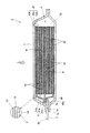
図1,図2の非水電解質二次電池(以下、電池)1は、例えばリチウムイオン二次電池であり、図1に示すように、扁平な長方形の外観形状を有し、長手方向の一方の端縁には一対の端子2,3を備えている。
<Example of battery configuration>
A non-aqueous electrolyte secondary battery (hereinafter referred to as a battery) 1 in FIGS. 1 and 2 is, for example, a lithium ion secondary battery, and has a flat rectangular external shape as shown in FIG. A pair of
この電池1は、図2に示すように、矢印X(扁平面)方向から見て長方形をなす発電要素4を電解質(図示省略)とともに2枚のラミネートフィルムからなる外装体5の内部に収容したものである。発電要素4は、セパレータ43を介して交互に積層された複数の正極板41および負極板42からなり、例えば、3枚の負極板42と、2枚の正極板41と、これらの間の4枚のセパレータ43と、を含んでいる。つまり、この例では、発電要素4の最外層に負極板42が位置している。但し、発電要素4の最外層に正極板41が位置する構成も可能である。なお、図2における各部の寸法は必ずしも正確なものではなく、説明のために誇張したものとなっている。
As shown in FIG. 2, the
正極板41は、図1,図2の矢印X方向から見て概略長方形をなす正極集電体41aの両面に正極活物質層41b,41cを形成したものである。正極集電体41aは、例えば、アルミニウム箔、アルミニウム合金箔、銅箔、又は、ニッケル箔等の電気化学的に安定した金属箔から構成されている。また、正極活物質層41b,41cは、例えば、ニッケル酸リチウム(LiNiO2)、マンガン酸リチウム(LiMnO2)、スピネル型マンガン酸リチウム(LiMn2O4)、または、コバルト酸リチウム(LiCoO2)等のリチウム複合酸化物からなる正極活物質と、バインダと、を混合したものを、正極集電体41aの主面に塗布することにより形成されている。ここで、リチウム複合酸化物の遷移金属(Ni,Mn,Co)の一部は、Li、Mg、B、Al、V、Cr、Fe、Co、Ni、Mn、W、またはTi等で置換されていてもよい。バインダとしては、ポリテトラフルオロエチレン、ポリフッ化ビニリデン、カルボキシメチルセルロース、スチレンブタジエンゴムなどが使用できる。また正極活物質層には、アセチレンブラック、カーボンブラック、黒鉛、繊維状炭素等の炭素材料からなる導電助剤を添加しても良い。
The
負極板42は、図1,図2の矢印X方向から見て概略長方形をなす負極集電体42aの両面に負極活物質層42b,42cを形成したものである。負極集電体42aは、例えば、銅箔、ステンレス箔、又は、鉄箔等の電気化学的に安定した金属箔から構成されている。負極活物質層42b,42cは、例えば、非晶質炭素、難黒鉛化炭素、易黒鉛化炭素、黒鉛、あるいは非晶質炭素で被覆された黒鉛等のような、リチウムイオンを吸蔵及び放出する負極活物質に、バインダを混合したものを、負極集電体42aの主面に塗布することにより形成されている。
The
負極活物質は、粒径としては0.1μm〜90μmであることが好ましく、BET比表面積としては0.1〜10m2/gであることが好ましい。バインダとしては、ポリテトラフルオロエチレン、ポリフッ化ビニリデン、カルボキシメチルセルロース、スチレンブタジエンゴムなどが使用できる。負極活物質層には、アセチレンブラック、カーボンブラック、黒鉛、繊維状炭素等の炭素材料からなる導電助剤を添加しても良い。 The negative electrode active material preferably has a particle size of 0.1 μm to 90 μm, and preferably has a BET specific surface area of 0.1 to 10 m 2 / g. As the binder, polytetrafluoroethylene, polyvinylidene fluoride, carboxymethyl cellulose, styrene butadiene rubber or the like can be used. You may add the conductive support agent which consists of carbon materials, such as acetylene black, carbon black, graphite, and fibrous carbon, to a negative electrode active material layer.
負極集電体42aの長手方向の端縁の一部は、負極活物質層42b,42cを具備しない延長部40として延びており、その延長部40の先端部40aが負極端子3における外装体5内側の一端部3aに接合されている。負極集電体42aが複数の場合には、それら負極集電体42aの各延長部40の先端部40aを束ねて一体にした状態にして接合する。
A part of the edge in the longitudinal direction of the negative electrode
この接合においては、例えば、延長部40の先端部40aを負極端子3の一端部3aに当接した状態で、超音波接合(超音波ホーンを先端部40aに当接して接合)する手法が挙げられる。また図2には示されていないが、同様に、正極集電体41aの長手方向の端縁の一部が、正極活物質層41b,41cを具備しない延長部(延長部40に相当;図示省略)として延びており、その延長部の先端部が正極端子2における外装体5内側の一端部に接合される。
In this joining, for example, there is a technique of performing ultrasonic joining (an ultrasonic horn is brought into contact with the
セパレータ43は、正極板41と負極板42との間の短絡を防止すると同時に電解質を保持する機能を有するものであって、例えば、ポリエチレン(PE)やポリプロピレン(PP)等のポリオレフィン等から構成される微多孔性膜からなる。なお、セパレータ43としては、ポリオレフィン等の単層膜に限られず、ポリプロピレン膜をポリエチレン膜でサンドイッチした三層構造のものや、ポリオレフィン微多孔性膜と有機不織布等を積層したものも用いることができる。また、シリカ、アルミナ、マグネシア、ジルコニア、チタニアなどの無機粒子をポリオレフィン微多孔膜の片面あるいは両面に付着させたものや、これらの無機粒子をポリオレフィン膜に分散させたものも用いることができる。あるいは耐熱性樹脂の多孔膜や粒子をポリオレフィン微多孔膜の片面あるいは両面に付着させたものでもよい。上記の粒子を多孔膜の表面に付着させる際に、正極あるいは負極の説明で述べたバインダを用いることもできる。
The
電極とセパレータを積層した構造の発電要素4を電解質とともに収容する外装体5は、フィルム状のものであれば特に限定はないが、図2に一部を拡大して示すように、例えば、熱融着層51と金属層52と保護層53との三層構造を有するラミネートフィルムからなる。中間の金属層52は、例えばアルミニウム箔からなり、その内側面を覆う熱融着層51は、熱融着が可能な合成樹脂例えばポリプロピレン(PP)からなり、金属層52の外側面を覆う保護層53は耐久性に優れた合成樹脂、例えばポリエチレンテレフタレート(PET)からなる。なお、さらに多数の層を有するラミネートフィルムを用いることもできる。また、前記の例では金属層52の両面に合成樹脂層を積層しているが、金属層52の外側の合成樹脂層は必ずしも必須のものではなく、内側表面にのみ合成樹脂層を備えた構成であってもよい。ラミネートフィルムの総厚さは、0.05〜0.8mmが好ましい。
The
外装体5は、一つの例では、図2の発電要素4の下面側に配置される1枚のラミネートフィルムと上面側に配置される他の1枚のラミネートフィルムとの2枚構造をなし、これら2枚のラミネートフィルムの周囲の4辺を重ね合わせ、かつ互いに熱融着した構成となっている。図示例は、2枚構造の外装体5を示している。また、他の一つの例では、外装体5は1枚の比較的大きなラミネートフィルムからなり、2つ折りとした状態で内側に発電要素4を配置した上で、周囲の3辺を重ね合わせ、かつ互いに熱融着した構成となっている。
In one example, the
長方形をなす電池1の短辺側に位置する一対の端子2,3は、外装体5のラミネートフィルムを熱融着する際に、外装体5内側の一端部(負極端子3の場合は一端部3a)にそれぞれ集電体41a,42aの延長部(集電体42aの場合は延長部40)に接合された状態で、外装体5外側の他端部(負極端子3の場合は他端部3b)がラミネートフィルムの接合面5aを通して外部へ引き出されている。そして、一対の端子2,3は、一端部と他端部との間(負極端子3の場合は一端部3aと他端部3bとの間)が外装体5のラミネートフィルムの接合面5aによって挟持され、その挟持された挟持部分3cにおいて封着されることになる。
A pair of
熱融着部と発電要素の間の距離は、外装体内部を減圧した状態で、たとえば1〜25mmが好ましい。1mm未満では貯留液を電極から充分に離間させることができない。25mmを超えると、長時間使用でも貯留液中の添加剤が電極に戻りにくくなり、本発明の効果が得られにくくなる。 The distance between the heat fusion part and the power generation element is preferably 1 to 25 mm, for example, in a state where the inside of the exterior body is decompressed. If it is less than 1 mm, the stored liquid cannot be sufficiently separated from the electrode. If it exceeds 25 mm, it becomes difficult for the additive in the stored liquid to return to the electrode even when used for a long time, and the effects of the present invention are hardly obtained.
<電解質の一例>
電解質としては、特に限定されるものではないが、リチウムイオン二次電池に一般的に使用される電解質として、例えば、有機溶媒にリチウム塩が溶解した非水電解質を用いることができる。有機溶媒としては、例えば、プロピレンカーボーネート、エチレンカーボネート、ジメチルカーボネート、ジエチルカーボネート、エチルメチルカーボネート等の溶媒を一種または二種以上組み合わせた溶媒を用いることができる。また、リチウム塩としては、例えば、LiPF6、LiBF4、LiCF3SO3、LiC4F9SO3、LiN(CF3SO2)2、LiC(CF3SO2)3等を好ましく用いることができる。
<Example of electrolyte>
The electrolyte is not particularly limited. For example, a non-aqueous electrolyte in which a lithium salt is dissolved in an organic solvent can be used as an electrolyte generally used in a lithium ion secondary battery. As the organic solvent, for example, a solvent obtained by combining one or more solvents such as propylene carbonate, ethylene carbonate, dimethyl carbonate, diethyl carbonate, and ethyl methyl carbonate can be used. Further, as the lithium salt, for example, LiPF 6 , LiBF 4 , LiCF 3 SO 3 , LiC 4 F 9 SO 3 , LiN (CF 3 SO 2 ) 2 , LiC (CF 3 SO 2 ) 3 or the like is preferably used. it can.
電解質量においては、余剰電解質分が含まれた量とする。ここで余剰電解質とは、外装体内に存在する全電解質の体積から、正極の空孔体積、負極の空孔体積、およびセパレータの空孔体積の合計(以下、発電要素の空孔体積)を差し引いた電解質量である。この値が正のとき、電解質量の倍率としては、発電要素の空孔体積の1倍を超えることになる。本発明におけるこの値の例としては、電極41,42およびセパレータ43の空孔体積の合計値(発電要素4の空孔体積)に対して、1倍超であればよいが、1.1倍〜1.6倍の電解質量となるように設定することが好ましく、倍率が1.2倍〜1.6倍であることがさらに好ましい。外装体5内に余剰電解質分を含む電解質が収容された状態で、外装体5の外側から発電要素の扁平面を加圧すると、余剰電解質が外装体5内における発電要素4の周辺部5bに移動(例えば発電要素4の各電極等の積層方向に対し垂直方向に移動)して貯留されることになり、本発明の効果を高めることができる。
In electrolytic mass, it is set as the quantity in which the excess electrolyte content was contained. Here, the surplus electrolyte is obtained by subtracting the total of the positive electrode void volume, the negative electrode void volume, and the separator void volume (hereinafter referred to as the void volume of the power generation element) from the total electrolyte volume present in the exterior body. Electrolytic mass. When this value is positive, the electrolytic mass magnification exceeds one time the pore volume of the power generation element. As an example of this value in the present invention, it may be more than 1 times the total value of the pore volumes of the
<添加剤の一例>
添加剤としては、充電工程の際に負極活物質(図2では負極活物質層42b,42c)により還元分解し活性面に添加剤由来皮膜を形成できるものであれば良く、種々のものを適用することができるが、例えばビニレンカーボネート(VC)、4−メチルビニレンカーボネート、4,5−ジメチルビニレンカーボネート、4−エチルビニレンカーボネート、4,5−ジエチルビニレンカーボネート、4−プロピルビニレンカーボネート、4,5−ジプロピルビニレンカーボネート、4−フェニルビニレンカーボネート、4,5−ジフェニルビニレンカーボネート、ビニルエチレンカーボネート(VEC)、ジビニルエチレンカーボネート、これらのカーボネート類の水素原子の一部がフッ素原子で置換された化合物、プロパンスルトンなどのスルトン、鎖状あるいは環状のスルホン酸エステル、鎖状あるいは環状のジスルホン酸エステルなどが挙げられる。これらの中でも、ビニレンカーボネート、ビニルエチレンカーボネート、ジビニルエチレンカーボネート、スルトン、フルオロエチレンカーボネートが好ましい。これらの添加剤は1種を単独でまたは2種以上を組み合わせて使用できる。
<Example of additive>
Any additive may be used as long as it can be reduced and decomposed by the negative electrode active material (the negative electrode active material layers 42b and 42c in FIG. 2) during the charging process to form an additive-derived film on the active surface. For example, vinylene carbonate (VC), 4-methyl vinylene carbonate, 4,5-dimethyl vinylene carbonate, 4-ethyl vinylene carbonate, 4,5-diethyl vinylene carbonate, 4-propyl vinylene carbonate, 4,5 -Dipropyl vinylene carbonate, 4-phenyl vinylene carbonate, 4,5-diphenyl vinylene carbonate, vinyl ethylene carbonate (VEC), divinyl ethylene carbonate, compounds in which some of hydrogen atoms of these carbonates are substituted with fluorine atoms, Propane sultone, etc. Examples include ruton, chain or cyclic sulfonate, and chain or cyclic disulfonate. Among these, vinylene carbonate, vinyl ethylene carbonate, divinyl ethylene carbonate, sultone, and fluoroethylene carbonate are preferable. These additives can be used alone or in combination of two or more.
添加剤量においては、加圧下での充電工程後(少なくとも初回の充電後)に外装体5内に残存する程度であれば良く、適宜設定することができるが、例えば電解質中の1重量%〜7重量%となるように添加することが好ましい。これにより、充電工程後(出荷時)の電解質中に例えば3000ppm以上の添加剤を残存させることができ、その後の充電工程に等より負極活物質に膨張由来活性面が形成された場合には、膨張由来活性面が露出しないように、添加剤由来皮膜を十分形成すると推測されるので好ましい。
The amount of the additive may be set as long as it remains in the
<製造手順および充電工程の一例>
電池1の製造手順としては、以下の通りである。まず、負極板42、セパレータ43および正極板41、セパレータ43を順次積層して発電要素4を構成し、負極板42の負極集電体42aの延長部40に対し負極端子3の内側端(一端部3a)を接合する。同様に、正極板41の正極集電体41aの延長部40に対し正極端子2の内側端(負極端子3の一端部3aに相当)を接合する。次に、この発電要素4を外装体5となるラミネートフィルムで覆いながら、比較的小さな充填口を残して周囲の4辺(2つ折りの場合は3辺)を熱融着する。そして、充填口を通して外装体5の内部に、余剰電解質分を含む電解質および少なくとも1種類以上の添加剤を充填し、外装体5内部を減圧し、その後、充填口を熱融着して外装体5を密閉状態とする。これにより電池1が完成する。
<Example of manufacturing procedure and charging process>
The manufacturing procedure of the
次に、完成した電池1を、加圧手段(加圧ホルダ等)に装填して外装体5の外側から電池の厚み方向に加圧することで発電要素の扁平面を加圧し、余剰電解質を外装体5内における発電要素4の周辺部5bに移動させて貯留した状態で、一対の端子2,3を介して所定条件で電圧を印加し少なくとも初回の充電を含む充電工程を行うことにより、発電要素4の各電極間に滞留した電解質に含まれる添加剤を還元分解し、負極活物質層42bにおける負極活物質表面に添加剤由来皮膜を形成する。ここで初回の充電とは、最初の充電のことであり、例えば、注液後に最初に、電池の充電方向に一定電流を流し電池の使用電圧範囲内の所定電圧になるまで通電を行ったり、使用電圧範囲の最大電圧に達するまで通電を行ったり、電圧変化が階段状に上昇していくように電流を変化させて通電をおこなったり、途中で一次的に通電を停止させたりすることを含む。
Next, the completed
そして、電池1を加圧手段から取り外して加圧を開放し、周辺部5bに貯留されていた余剰電解質を例えば発電要素4の各電極間に移動させる。これにより、例えば更なる充電工程(少なくとも初回の充電以降の充電)を行った場合に、負極活物質が膨張し膨張由来の活性面が生じても、余剰電解質中の添加剤が還元分解し、膨張由来活性面に付着して添加剤由来皮膜が形成されることで本発明の効果が得られると推測される。
And the
加圧手段は、発電要素4や外装体5を損傷させない程度で電池を外装体5の外側から加圧するものであって、余剰電解質を発電要素4の周辺部5bに移動させて貯留する程度に加圧できるものであれば良く、種々の形態のものを適用できるが、例えば図3に示すように、外装体5の厚さ方向から、緩衝体60を被覆した2枚の加圧板61を押しつけて加圧(図示矢印Y方向に加圧)する一軸加圧手段が挙げられる。緩衝体60としては、例えば、シリコンゴムなどの弾性を有する高分子材料あるいは布を用いることが挙げられる。加圧板61としては、例えば、ステンレス製板等の金属板,ガラス製板、樹脂板あるいはセラミック製板などの絶縁性固体板を用いることが挙げられる。
The pressurizing means pressurizes the battery from the outside of the
例えば図1,図2に示したような構造の電池1において、発電要素4や外装体5を損傷させない程度で外装体5の外側から電池を加圧するには、加圧力を約0.49×10⁻²MPa(0.05kgf/cm2)〜約24.5×10-2MPa(2.5kgf/cm2)の範囲に設定することが好ましい。また、この加圧力の範囲で外装体5の外側から電池を加圧した際の発電要素の積層方向の厚さに対する電池の厚さ(以下、厚さ比率)は、1.02倍〜1.07倍程度になる。このような加圧力や厚さとすることで、本発明の効果をより高めることができる。なお、ここでいう厚さ比率の分母は、電解質を含んでいないときの発電要素単体の初期厚さであり、分子は外装体に電解質とともに発電要素を外装体内に収納した状態の電池の外形の厚さ(外装体厚さ含む)である。たとえば発電要素内に電解質を過剰に含んだ状態では、正負極板とセパレータの間隔が広くなって、過剰分が多くなるほど厚さ比率は大きくなる傾向がある。
For example, in the
また、初回の充電の際に加圧を行うことが挙げられるが、初回の充電の後の充電においても加圧を行っても良く、例えば負極活物質において膨張由来活性面が出現し始めるタイミングを鑑みて適宜加圧することが好ましい。 In addition, the pressure may be applied at the time of the first charge, but the pressure may be applied even after the first charge, for example, the timing at which the expansion-derived active surface starts to appear in the negative electrode active material. In view of this, it is preferable to pressurize appropriately.
本実施形態では、正極板および負極板をセパレータを介して積層してなる扁平な発電要素を、金属層の少なくとも内側表面に樹脂層を積層したラミネートフィルムからなる外装体の内部に、余剰電解質分を含む非水電解質および少なくとも1種類以上の電解質添加剤とともに収容して、外装体の外側から発電要素の扁平面を加圧した状態で、少なくとも初回の充電を行うようにしたので、電池の諸特性を向上させることが可能となる。あるいは、正極板および負極板をセパレータを介して積層してなる発電要素が、金属層の少なくとも内側表面に樹脂層を積層したラミネートフィルムからなる外装体の内部に、余剰電解質分を含む非水電解質および少なくとも1種類以上の電解質添加剤とともに収容され、端子を導出した状態で外装体が密封されて、少なくとも初回の充電を含む充電工程が行われた扁平な非水電解質二次電池において、充電工程後の非水電解質中に残存する電解質添加剤が3000ppm以上であり、かつ非水電解質量が発電要素の空孔体積の1.1倍〜1.6倍となるようにしたので、電池の諸特性を向上させることが可能となる。 In this embodiment, a flat power generating element formed by laminating a positive electrode plate and a negative electrode plate with a separator interposed between the surplus electrolyte component and the inside of an exterior body made of a laminate film in which a resin layer is laminated on at least the inner surface of the metal layer. The battery is stored together with a nonaqueous electrolyte containing at least one kind of electrolyte additive, and at least the first charge is performed in a state where the flat surface of the power generation element is pressurized from the outside of the exterior body. The characteristics can be improved. Alternatively, a non-aqueous electrolyte in which a power generation element formed by laminating a positive electrode plate and a negative electrode plate via a separator includes an excess electrolyte component inside an exterior body made of a laminate film in which a resin layer is laminated on at least an inner surface of a metal layer In the flat nonaqueous electrolyte secondary battery, which is housed together with at least one kind of electrolyte additive and the outer body is sealed in a state where the terminal is led out, and the charging process including at least the first charging is performed, the charging process Since the electrolyte additive remaining in the later non-aqueous electrolyte is 3000 ppm or more and the non-aqueous electrolytic mass is 1.1 to 1.6 times the pore volume of the power generation element, The characteristics can be improved.
その理由は明らかではないが、以下の作用が考えられる。初回の充電工程において、外装体の外側から発電要素の扁平面を加圧した状態とすることにより、余剰電解質を発電要素の周辺に移動(例えば発電要素の各電極等の積層方向に対し垂直方向に移動)させて溜めておくことができ、これにより電極から離間しているので、この余剰電解質に含まれる添加剤が初回の充電時に還元分解に使用されることを抑制でき、さらに、発電要素の周辺に溜めた余剰電解質が、電池の加圧を開放することにより、例えば発電要素の各電極間に移動し、この後、例えば更なる充放電を行うことにより膨張由来活性面が形成された場合、余剰電解質中の添加剤(発電要素の周辺に溜められていた添加剤)が還元分解され、膨張由来活性面に対して添加剤由来皮膜が形成されると推測される。これにより、初回の充電時に形成された添加剤由来皮膜に例えば罅割れ等ができて新たに出現した膨張由来活性面が、再度添加剤由来皮膜で保護されるため、電池の諸特性が向上すると考えられる。 The reason is not clear, but the following actions are considered. In the first charging step, the surplus electrolyte is moved to the periphery of the power generation element by pressing the flat surface of the power generation element from the outside of the outer package (for example, the direction perpendicular to the stacking direction of each electrode of the power generation element) Since it is separated from the electrode, the additive contained in the surplus electrolyte can be prevented from being used for reductive decomposition during the first charge, and the power generation element The surplus electrolyte accumulated in the periphery of the battery moves, for example, between the electrodes of the power generation element by releasing the pressurization of the battery, and thereafter, the expansion-derived active surface is formed by, for example, further charging / discharging. In this case, it is presumed that the additive in the surplus electrolyte (additive stored in the vicinity of the power generation element) is reduced and decomposed to form an additive-derived film on the expansion-derived active surface. As a result, the additive-derived film formed at the first charge, for example, can be cracked, and the newly expanded expansion-derived active surface is again protected by the additive-derived film, so that various characteristics of the battery are improved. Conceivable.
<実施例>
正極を以下のように作製した。スピネル構造を有するLi1.1Mn1.9O4粉末と、リチウム・ニッケル・コバルト・マンガン複合酸化物と、バインダ樹脂としてポリフッ化ビニリデンと、導電助剤としてカーボンブラック粉末とを、所定の割合で、溶媒であるN−メチル−2−ピロリドン(NMP)中に均一に分散させてスラリーを作製した。得られたスラリーを、正極集電体となる厚み20μmのアルミニウム箔上に塗布した後NMPを蒸発させることにより正極活物質層を形成した。更に、正極活物質層をプレスすることによって、正極集電体の片面上に正極活物質層を塗布した。同様に他方の面にも活物質層を塗布し、正極を得た。
<Example>
A positive electrode was produced as follows. Li 1.1 Mn 1.9 O 4 powder having a spinel structure, lithium / nickel / cobalt / manganese composite oxide, polyvinylidene fluoride as a binder resin, and carbon black powder as a conductive additive at a predetermined ratio in a solvent. A slurry was prepared by uniformly dispersing in some N-methyl-2-pyrrolidone (NMP). The obtained slurry was applied on an aluminum foil having a thickness of 20 μm serving as a positive electrode current collector, and then NMP was evaporated to form a positive electrode active material layer. Furthermore, the positive electrode active material layer was applied to one side of the positive electrode current collector by pressing the positive electrode active material layer. Similarly, an active material layer was applied to the other surface to obtain a positive electrode.
負極を以下のように作製した。負極活物質として非晶質性炭素で被覆された球状天然黒鉛粉末(平均粒子径:20μm)とカーボンブラック系導電助剤をバインダーのスチレンブタジエンゴムとカルボキシメチルセルロースの水溶液に所定の割合で均一に分散させてスラリーを作製した。得られたスラリーを、負極集電体となる厚み15μmの銅箔上に塗布した後水を蒸発させることにより負極活物質層を形成した。更に、負極活物質層をプレスすることによって、負極集電体の片面上に負極活物質層を塗布した負極を作製した。同様に他方の面にも活物質層を塗布し、負極を得た。 The negative electrode was produced as follows. Spherical natural graphite powder (average particle size: 20 μm) coated with amorphous carbon as a negative electrode active material and a carbon black-based conductive additive are uniformly dispersed in an aqueous solution of styrene butadiene rubber and carboxymethyl cellulose as a binder at a predetermined ratio. To prepare a slurry. The obtained slurry was applied onto a 15 μm thick copper foil serving as a negative electrode current collector, and then water was evaporated to form a negative electrode active material layer. Furthermore, the negative electrode which apply | coated the negative electrode active material layer on the single side | surface of the negative electrode collector was produced by pressing a negative electrode active material layer. Similarly, an active material layer was applied to the other surface to obtain a negative electrode.
正極および負極を、活物質が塗布されていない集電体延長部を残しつつ、所定寸法に裁断して正極板、負極板を得た。次にポリエチレン及びポリプロピレンからなるセパレータの両面に上記負極と正極とを活物質層がセパレータを隔てて重なるように交互に所定枚数積層して発電要素を得た。 The positive electrode and the negative electrode were cut into predetermined dimensions while leaving a current collector extension portion to which no active material was applied, to obtain a positive electrode plate and a negative electrode plate. Next, a predetermined number of the negative electrode and the positive electrode were alternately laminated on both sides of a separator made of polyethylene and polypropylene so that the active material layers overlapped with the separator interposed therebetween to obtain a power generation element.
次に負極板の負極集電体の延長部に対し負極端子の内側端(一端部)を接合した。同様に、正極板の正極集電体の延長部に対し正極端子の内側端(一端部)を接合した。この発電要素を外装体となるラミネートフィルムで覆いながら、比較的小さな充填口を残して周囲の4辺を熱融着した後、充填口に下記に述べる電解質を注液し、外装体内部を減圧し、その後、充填口を熱融着して外装体を密閉状態とした。4辺のうち1辺は、正極端子および負極端子を引き出した状態でラミネートフィルムの熱融着を行った。熱融着部と発電要素の間の距離は、端子引き出し辺においては15mm、それ以外の辺においては5mmとした。 Next, the inner end (one end) of the negative electrode terminal was joined to the extension of the negative electrode current collector of the negative electrode plate. Similarly, the inner end (one end) of the positive electrode terminal was joined to the extension of the positive electrode current collector of the positive electrode plate. While covering this power generating element with the laminate film that forms the exterior body, heat seal the four surrounding sides leaving a relatively small filling port, and then inject the electrolyte described below into the filling port to reduce the pressure inside the exterior body. Thereafter, the filling port was heat-sealed to seal the outer package. One side of the four sides was heat-sealed with the laminate film in a state where the positive electrode terminal and the negative electrode terminal were pulled out. The distance between the heat-sealed portion and the power generation element was 15 mm at the terminal lead-out side and 5 mm at the other sides.
電解質としては、1mol/LのLiPF6とエチレンカーボネートとジエチルカーボネートの混合溶媒(体積比3:7)とからなる電解質に、ビニレンカーボネートを各試料ごとに決められた所定量添加したものを用いた。こうして、図1,図2に示した構造の電池の試料S1〜S7(実施例1,3,5,7、参考例2,4,6)と試料P1,P2(比較例1,2)を、下記の各評価用に試料番号ごとにそれぞれ3つずつ(一部試料は2つずつ)作製した。 As the electrolyte, an electrolyte composed of 1 mol / L LiPF6 and a mixed solvent of ethylene carbonate and diethyl carbonate (volume ratio 3: 7) was added with a predetermined amount of vinylene carbonate determined for each sample. Thus, samples S1 to S7 (Examples 1 , 3, 5, 7 and Reference Examples 2, 4, 6 ) and Samples P1, P2 (Comparative Examples 1 and 2) of the battery having the structure shown in FIGS. For each of the following evaluations, three samples were prepared for each sample number (some samples were two).
そして、各試料において、図3に示したような加圧手段(加圧板61の材質はステンレス)によりそれぞれの試料条件で外装体5の外側から電池を加圧しながら初回の充電(試料P1は加圧せずに初回の充電)を行った。このように準備した電池試料に対し、初回の充電後の外装体5内の電解質中添加剤残存量(ppm)、サイクル試験容量維持率(45℃の温度下で500サイクル試験を行った後の容量維持率(%)),および保存試験抵抗上昇率(45℃の温度下で16週間放置した後の抵抗上昇率(%))を調べた。
Then, in each sample, the first charge (sample P1 is applied while pressing the battery from the outside of the
なお、各試料の電解質量(発電要素の空孔体積に対する電解質量(倍率)),添加剤量(重量%),加圧力(MPa),厚さ比率(倍率)は、表1に示すとおりである。 In addition, the electrolytic mass (electrolytic mass (magnification) with respect to the pore volume of the power generation element), additive amount (% by weight), applied pressure (MPa), and thickness ratio (magnification) of each sample are as shown in Table 1. is there.

表1に示すように、比較例の試料P1,P2は、サイクル試験容量維持率は低く抵抗上昇率が高い結果となった。これは、試料P1の場合、電解質量が比較的多い(余剰電解質分を含む)が、加圧せずに初回の充電を行ったために、発電要素内に余剰分を含む電解質の殆どが含まれたままとなって電池厚さが厚くなり、初回の充電終了前に添加剤の殆どが還元分解により消費され(添加剤残留が920ppmと比較的少ない)、負極活物質の膨張前の活性面に添加剤由来皮膜を形成できたとしても、負極活物質膨張後の膨張由来活性面には添加剤由来皮膜が殆ど形成されなかったことに起因すると推測される。また、試料P2の場合は、電解質内に添加剤が含まれていないため、たとえ加圧しながら初回の充電を行っても、活性面に対して電解質由来皮膜のみが形成されたと推測される。 As shown in Table 1, the samples P1 and P2 of the comparative example had a low cycle test capacity retention rate and a high resistance increase rate. This is because, in the case of the sample P1, the electrolytic mass is relatively large (including surplus electrolyte content), but most of the electrolyte including surplus content is included in the power generation element because the initial charge was performed without applying pressure. As a result, the battery thickness increases, and most of the additive is consumed by reductive decomposition before the end of the first charge (remaining additive is relatively low at 920 ppm). Even if the additive-derived film can be formed, it is presumed that the additive-derived film was hardly formed on the expansion-derived active surface after expansion of the negative electrode active material. In the case of sample P2, since no additive is contained in the electrolyte, it is assumed that only the electrolyte-derived film was formed on the active surface even if the first charge was performed while applying pressure.
一方、実施例の試料S1,S3,S5,S7、および参考例の試料S2,S4,S6は、比較例の試料P1,P2と比較して、サイクル試験容量維持率は高く保存試験抵抗上昇率が低く抑えられた結果となった。これは、電解質量が比較的多く(余剰電解質分を含む)、加圧しながら初回の充電を行ったために、余剰電解質が外装体5内における周辺部5bに移動して、初回の充電後においても多くの添加剤が周辺部5bにおける電解質中に残存(例えば試料S1〜S7のように3000ppm以上残存)し、それが初回の充電後、あるいはサイクル試験中や高温保存試験中に有効に作用して、膨張由来活性面を含む活性面に対して添加剤由来皮膜を十分形成できたことに起因すると推測される。試料S1,S2,S3,S5同士を比較し、添加剤残留量が多いほどサイクル特性が良く抵抗上昇率も低い傾向があることも、上記の推測メカニズムを支持する。
On the other hand, the samples S1 , S3, S5, and S7 of the example and the samples S2, S4, and S6 of the reference example have a higher cycle test capacity retention rate and an increase in the storage test resistance than the samples P1 and P2 of the comparative example. The result was a low rate. This is because the electrolytic mass is relatively large (including the surplus electrolyte content), and the first charge was performed while pressurizing, so that the surplus electrolyte moved to the
なお、試料P1において、試料S1〜S7と同様に初回の充電を加圧しながら行ったところ、初回の充電後においても多くの添加剤が外装体5内に残存し、その結果、寿命特性が向上することを確認した。
In Sample P1, the first charge was performed while applying pressure as in Samples S1 to S7. As a result, many additives remained in the
以上、本実施例について詳細に説明したが、本発明の技術思想の範囲で多彩な変更等が可能であることは、当業者にとって明白なことであり、このような変更等が特許請求の範囲に属することは当然のことである。 Although the present embodiment has been described in detail above, it is obvious to those skilled in the art that various modifications and the like are possible within the scope of the technical idea of the present invention, and such modifications and the like are within the scope of the claims. It is natural to belong to.
たとえば、上述した例では所定枚数の正負極板をセパレータを介して交互に積層した扁平な発電要素を用いた例を示しているが、扁平な巻回型の発電要素を使用することも可能である。この場合、電解質を過剰に含む発電要素の扁平面を加圧したとき、電解質は巻回軸方向に押し出されることになるが、本発明の効果は得られる。 For example, in the above-described example, a flat power generation element in which a predetermined number of positive and negative electrode plates are alternately stacked via separators is shown, but a flat wound power generation element can also be used. is there. In this case, when the flat surface of the power generation element containing excessive electrolyte is pressurized, the electrolyte is pushed out in the direction of the winding axis, but the effect of the present invention can be obtained.
1…電池
2,3…端子
4…発電要素
41…正極板
42…負極板
43…セパレータ
5…外装体
5b…周辺部
DESCRIPTION OF
Claims (3)
外装体の外側から発電要素の扁平面を加圧した状態で、少なくとも初回の充電を含む充電工程と、
充電工程の後に、余剰電解質を発電要素の電極間に移動させるように加圧を開放する工程と、を行い、
加圧の加圧力が0.98×10 -2 MPa〜24.5×10 -2 MPaであり、
非水電解液中の電解液添加剤量が3重量%〜7重量%であり、
電解液添加剤は、負極活物質表面で還元分解して皮膜形成し、
少なくとも初回の充電を含む充電工程を行った後の非水電解液中に残存する電解液添加剤が4000ppm以上6259ppm以下であることを特徴とする非水電解質二次電池の製造方法。 A flat power generation element formed by laminating a positive electrode plate and a negative electrode plate with a separator interposed between a non-aqueous electrolyte solution containing an excess electrolyte solution and at least one type of film capable of forming a film inside a film-like outer package. Housed with liquid additive,
In a state where the flat surface of the power generation element is pressurized from the outside of the exterior body, a charging step including at least the first charging,
After the charging step, performing a step of releasing pressure so as to move the surplus electrolyte between the electrodes of the power generation element,
Pressure of the pressure is 0.98 × 10 -2 MPa~24.5 × 10 -2 MPa,
The amount of the electrolyte additive in the non-aqueous electrolyte is 3% by weight to 7% by weight,
The electrolyte additive forms a film by reductive decomposition on the negative electrode active material surface ,
Non-aqueous method for producing electrolyte secondary battery electrolyte additive is characterized in der Rukoto than 6259ppm or less 4000ppm remaining in the non-aqueous electrolytic solution after the charging process including at least initial charge.
Priority Applications (6)
| Application Number | Priority Date | Filing Date | Title |
|---|---|---|---|
| JP2013202446A JP6283487B2 (en) | 2013-09-27 | 2013-09-27 | Method for producing non-aqueous electrolyte secondary battery |
| EP14847421.6A EP3051621A4 (en) | 2013-09-27 | 2014-06-09 | Nonaqueous electrolyte secondary battery and method for manufacturing same |
| KR1020167008570A KR101958070B1 (en) | 2013-09-27 | 2014-06-09 | Nonaqueous electrolyte secondary battery and method for manufacturing same |
| US15/024,068 US10044071B2 (en) | 2013-09-27 | 2014-06-09 | Nonaqueous electrolyte secondary battery and method for manufacturing same |
| CN201480052807.8A CN105580194B (en) | 2013-09-27 | 2014-06-09 | non-aqueous electrolyte secondary battery and its manufacturing method |
| PCT/JP2014/065178 WO2015045493A1 (en) | 2013-09-27 | 2014-06-09 | Nonaqueous electrolyte secondary battery and method for manufacturing same |
Applications Claiming Priority (1)
| Application Number | Priority Date | Filing Date | Title |
|---|---|---|---|
| JP2013202446A JP6283487B2 (en) | 2013-09-27 | 2013-09-27 | Method for producing non-aqueous electrolyte secondary battery |
Publications (3)
| Publication Number | Publication Date |
|---|---|
| JP2015069810A JP2015069810A (en) | 2015-04-13 |
| JP2015069810A5 JP2015069810A5 (en) | 2016-04-21 |
| JP6283487B2 true JP6283487B2 (en) | 2018-02-21 |
Family
ID=52742651
Family Applications (1)
| Application Number | Title | Priority Date | Filing Date |
|---|---|---|---|
| JP2013202446A Active JP6283487B2 (en) | 2013-09-27 | 2013-09-27 | Method for producing non-aqueous electrolyte secondary battery |
Country Status (6)
| Country | Link |
|---|---|
| US (1) | US10044071B2 (en) |
| EP (1) | EP3051621A4 (en) |
| JP (1) | JP6283487B2 (en) |
| KR (1) | KR101958070B1 (en) |
| CN (1) | CN105580194B (en) |
| WO (1) | WO2015045493A1 (en) |
Families Citing this family (21)
| Publication number | Priority date | Publication date | Assignee | Title |
|---|---|---|---|---|
| US10629947B2 (en) | 2008-08-05 | 2020-04-21 | Sion Power Corporation | Electrochemical cell |
| EP2669975A1 (en) | 2008-08-05 | 2013-12-04 | Sion Power Corporation | Application of force in electrochemical cells |
| KR101807911B1 (en) | 2011-06-17 | 2017-12-11 | 시온 파워 코퍼레이션 | Plating technique for electrode |
| JP2017010933A (en) * | 2015-06-19 | 2017-01-12 | 株式会社半導体エネルギー研究所 | Power storage device charging method, method of manufacturing power storage device, battery module and vehicle |
| KR101944226B1 (en) * | 2015-07-09 | 2019-01-30 | 닛산 지도우샤 가부시키가이샤 | Non-aqueous electrolyte secondary battery |
| JP6826816B2 (en) * | 2016-03-31 | 2021-02-10 | 株式会社エンビジョンAescジャパン | Lithium ion secondary battery |
| JP6547768B2 (en) * | 2017-01-17 | 2019-07-24 | トヨタ自動車株式会社 | Method of manufacturing all solid lithium ion battery |
| WO2018173700A1 (en) * | 2017-03-24 | 2018-09-27 | 株式会社村田製作所 | Secondary battery manufacturing method and manufacturing device |
| US10868306B2 (en) | 2017-05-19 | 2020-12-15 | Sion Power Corporation | Passivating agents for electrochemical cells |
| KR102664549B1 (en) | 2017-05-19 | 2024-05-09 | 시온 파워 코퍼레이션 | Passivation agent for electrochemical cells |
| JP7029922B2 (en) * | 2017-10-10 | 2022-03-04 | 日産自動車株式会社 | Manufacturing method of electrodes for non-aqueous electrolyte secondary batteries |
| JP6926972B2 (en) * | 2017-11-10 | 2021-08-25 | トヨタ自動車株式会社 | Manufacturing method of all-solid-state battery |
| JP7085390B2 (en) * | 2018-04-09 | 2022-06-16 | 日産自動車株式会社 | Battery manufacturing method |
| EP3823075A4 (en) * | 2018-07-13 | 2022-06-29 | Hitachi Zosen Corporation | Installation for manufacturing all-solid secondary battery |
| US11791511B2 (en) | 2019-11-19 | 2023-10-17 | Sion Power Corporation | Thermally insulating compressible components for battery packs |
| WO2021102071A1 (en) | 2019-11-19 | 2021-05-27 | Sion Power Corporation | Batteries, and associated systems and methods |
| US11984575B2 (en) | 2019-11-19 | 2024-05-14 | Sion Power Corporation | Battery alignment, and associated systems and methods |
| US11978917B2 (en) | 2019-11-19 | 2024-05-07 | Sion Power Corporation | Batteries with components including carbon fiber, and associated systems and methods |
| WO2021183858A1 (en) | 2020-03-13 | 2021-09-16 | Sion Power Corporation | Application of pressure to electrochemical devices including deformable solids, and related systems |
| KR20220066470A (en) * | 2020-11-16 | 2022-05-24 | 주식회사 엘지에너지솔루션 | Method for formationing battery cell and method for manufacturing battery cell including the same |
| WO2024147290A1 (en) * | 2023-01-05 | 2024-07-11 | 株式会社Gsユアサ | Nonaqueous-electrolyte electricity storage element |
Family Cites Families (8)
| Publication number | Priority date | Publication date | Assignee | Title |
|---|---|---|---|---|
| JP4348771B2 (en) | 1999-04-21 | 2009-10-21 | パナソニック株式会社 | Lithium secondary battery |
| JP3533117B2 (en) * | 1999-07-23 | 2004-05-31 | 日本電気株式会社 | Method of manufacturing film-covered battery |
| JP2002216849A (en) * | 2001-01-15 | 2002-08-02 | Mitsubishi Cable Ind Ltd | Manufacturing method of lithium ion secondary cell |
| JP4867208B2 (en) * | 2005-06-15 | 2012-02-01 | 三菱化学株式会社 | Lithium secondary battery |
| CN101420048A (en) * | 2007-10-26 | 2009-04-29 | 比亚迪股份有限公司 | Preparation of lithium ionic secondary cell |
| JP5263954B2 (en) * | 2008-11-25 | 2013-08-14 | Necエナジーデバイス株式会社 | Lithium ion secondary battery and manufacturing method thereof |
| JP5574404B2 (en) * | 2009-07-16 | 2014-08-20 | Necエナジーデバイス株式会社 | Lithium ion secondary battery |
| KR101543939B1 (en) * | 2011-03-03 | 2015-08-11 | 도요타지도샤가부시키가이샤 | Nonaqueous electrolytic-solution rechargeable battery |
-
2013
- 2013-09-27 JP JP2013202446A patent/JP6283487B2/en active Active
-
2014
- 2014-06-09 CN CN201480052807.8A patent/CN105580194B/en active Active
- 2014-06-09 WO PCT/JP2014/065178 patent/WO2015045493A1/en active Application Filing
- 2014-06-09 KR KR1020167008570A patent/KR101958070B1/en active IP Right Grant
- 2014-06-09 EP EP14847421.6A patent/EP3051621A4/en not_active Withdrawn
- 2014-06-09 US US15/024,068 patent/US10044071B2/en active Active
Also Published As
| Publication number | Publication date |
|---|---|
| CN105580194A (en) | 2016-05-11 |
| CN105580194B (en) | 2018-06-26 |
| KR20160048982A (en) | 2016-05-04 |
| KR101958070B1 (en) | 2019-03-13 |
| US10044071B2 (en) | 2018-08-07 |
| WO2015045493A1 (en) | 2015-04-02 |
| EP3051621A1 (en) | 2016-08-03 |
| EP3051621A4 (en) | 2016-09-14 |
| US20160218398A1 (en) | 2016-07-28 |
| JP2015069810A (en) | 2015-04-13 |
Similar Documents
| Publication | Publication Date | Title |
|---|---|---|
| JP6283487B2 (en) | Method for producing non-aqueous electrolyte secondary battery | |
| JP6403278B2 (en) | Lithium ion secondary battery | |
| JP6644658B2 (en) | Lithium ion battery | |
| CN109088091A (en) | Lithium ion secondary battery element and lithium ion secondary battery | |
| JP6024990B2 (en) | Method for producing non-aqueous electrolyte secondary battery | |
| US10686182B2 (en) | Secondary battery | |
| KR101846767B1 (en) | Nonaqueous electrolyte secondary battery | |
| JP2007087652A (en) | Nonaqueous electrolyte battery | |
| JP2016219143A (en) | Secondary battery | |
| JP5820704B2 (en) | Stacked battery | |
| JPWO2017212597A1 (en) | Non-aqueous electrolyte secondary battery | |
| WO2014050114A1 (en) | Non-aqueous electrolyte secondary battery | |
| JP2012151036A (en) | Laminated battery | |
| WO2017169417A1 (en) | Lithium-ion secondary battery | |
| JP6619562B2 (en) | Nonaqueous electrolyte secondary battery | |
| KR101709391B1 (en) | Nonaqueous electrolyte secondary battery | |
| JP2018163855A (en) | Nonaqueous electrolyte secondary battery | |
| JP6781074B2 (en) | Rechargeable battery | |
| JP2019169307A (en) | Electrochemical element | |
| JP2019102231A (en) | Power storage element | |
| JP6753802B2 (en) | Rechargeable battery | |
| JP2011233408A (en) | Nonaqueous electrolyte secondary battery | |
| JP6342697B2 (en) | Nonaqueous electrolyte secondary battery | |
| JP7430665B2 (en) | Secondary battery current collector and its manufacturing method, and secondary battery | |
| WO2012043119A1 (en) | Nonaqueous electrolyte secondary battery |
Legal Events
| Date | Code | Title | Description |
|---|---|---|---|
| A521 | Request for written amendment filed |
Free format text: JAPANESE INTERMEDIATE CODE: A523 Effective date: 20160308 |
|
| A621 | Written request for application examination |
Free format text: JAPANESE INTERMEDIATE CODE: A621 Effective date: 20160308 |
|
| A131 | Notification of reasons for refusal |
Free format text: JAPANESE INTERMEDIATE CODE: A131 Effective date: 20170214 |
|
| A521 | Request for written amendment filed |
Free format text: JAPANESE INTERMEDIATE CODE: A523 Effective date: 20170412 |
|
| A02 | Decision of refusal |
Free format text: JAPANESE INTERMEDIATE CODE: A02 Effective date: 20170808 |
|
| A521 | Request for written amendment filed |
Free format text: JAPANESE INTERMEDIATE CODE: A523 Effective date: 20171031 |
|
| A521 | Request for written amendment filed |
Free format text: JAPANESE INTERMEDIATE CODE: A821 Effective date: 20171031 |
|
| A911 | Transfer to examiner for re-examination before appeal (zenchi) |
Free format text: JAPANESE INTERMEDIATE CODE: A911 Effective date: 20171120 |
|
| TRDD | Decision of grant or rejection written | ||
| A01 | Written decision to grant a patent or to grant a registration (utility model) |
Free format text: JAPANESE INTERMEDIATE CODE: A01 Effective date: 20180123 |
|
| A61 | First payment of annual fees (during grant procedure) |
Free format text: JAPANESE INTERMEDIATE CODE: A61 Effective date: 20180129 |
|
| R150 | Certificate of patent or registration of utility model |
Ref document number: 6283487 Country of ref document: JP Free format text: JAPANESE INTERMEDIATE CODE: R150 |
|
| S111 | Request for change of ownership or part of ownership |
Free format text: JAPANESE INTERMEDIATE CODE: R313115 |
|
| R350 | Written notification of registration of transfer |
Free format text: JAPANESE INTERMEDIATE CODE: R350 |
|
| S533 | Written request for registration of change of name |
Free format text: JAPANESE INTERMEDIATE CODE: R313533 |
|
| R350 | Written notification of registration of transfer |
Free format text: JAPANESE INTERMEDIATE CODE: R350 |
|
| R250 | Receipt of annual fees |
Free format text: JAPANESE INTERMEDIATE CODE: R250 |
|
| R250 | Receipt of annual fees |
Free format text: JAPANESE INTERMEDIATE CODE: R250 |
|
| R250 | Receipt of annual fees |
Free format text: JAPANESE INTERMEDIATE CODE: R250 |