JP6282071B2 - Air conditioning control system and air conditioning control method - Google Patents
Air conditioning control system and air conditioning control method Download PDFInfo
- Publication number
- JP6282071B2 JP6282071B2 JP2013196946A JP2013196946A JP6282071B2 JP 6282071 B2 JP6282071 B2 JP 6282071B2 JP 2013196946 A JP2013196946 A JP 2013196946A JP 2013196946 A JP2013196946 A JP 2013196946A JP 6282071 B2 JP6282071 B2 JP 6282071B2
- Authority
- JP
- Japan
- Prior art keywords
- power
- heat storage
- air conditioning
- heat
- load
- Prior art date
- Legal status (The legal status is an assumption and is not a legal conclusion. Google has not performed a legal analysis and makes no representation as to the accuracy of the status listed.)
- Active
Links
- 238000004378 air conditioning Methods 0.000 title claims description 114
- 238000000034 method Methods 0.000 title claims description 32
- 238000005338 heat storage Methods 0.000 claims description 138
- 230000005855 radiation Effects 0.000 claims description 32
- 238000005265 energy consumption Methods 0.000 claims description 23
- 238000012545 processing Methods 0.000 claims description 22
- 238000002485 combustion reaction Methods 0.000 claims description 18
- 230000017525 heat dissipation Effects 0.000 claims description 11
- 239000003507 refrigerant Substances 0.000 claims description 9
- 230000007274 generation of a signal involved in cell-cell signaling Effects 0.000 claims description 7
- XLYOFNOQVPJJNP-UHFFFAOYSA-N water Substances O XLYOFNOQVPJJNP-UHFFFAOYSA-N 0.000 description 49
- 238000001816 cooling Methods 0.000 description 15
- 239000000498 cooling water Substances 0.000 description 12
- 238000010586 diagram Methods 0.000 description 8
- 238000010248 power generation Methods 0.000 description 6
- 238000006243 chemical reaction Methods 0.000 description 3
- 238000005286 illumination Methods 0.000 description 3
- 230000002123 temporal effect Effects 0.000 description 3
- 238000012546 transfer Methods 0.000 description 3
- 239000003990 capacitor Substances 0.000 description 2
- 239000002826 coolant Substances 0.000 description 2
- 230000000694 effects Effects 0.000 description 2
- 230000005611 electricity Effects 0.000 description 2
- HBBGRARXTFLTSG-UHFFFAOYSA-N Lithium ion Chemical compound [Li+] HBBGRARXTFLTSG-UHFFFAOYSA-N 0.000 description 1
- 230000003750 conditioning effect Effects 0.000 description 1
- 230000007423 decrease Effects 0.000 description 1
- 230000003111 delayed effect Effects 0.000 description 1
- 238000007599 discharging Methods 0.000 description 1
- 239000000945 filler Substances 0.000 description 1
- 230000006870 function Effects 0.000 description 1
- 238000009434 installation Methods 0.000 description 1
- 229910001416 lithium ion Inorganic materials 0.000 description 1
- 238000012986 modification Methods 0.000 description 1
- 230000004048 modification Effects 0.000 description 1
- 238000005057 refrigeration Methods 0.000 description 1
- 238000013517 stratification Methods 0.000 description 1
- 239000013589 supplement Substances 0.000 description 1
Images


Classifications
-
- F—MECHANICAL ENGINEERING; LIGHTING; HEATING; WEAPONS; BLASTING
- F24—HEATING; RANGES; VENTILATING
- F24F—AIR-CONDITIONING; AIR-HUMIDIFICATION; VENTILATION; USE OF AIR CURRENTS FOR SCREENING
- F24F11/00—Control or safety arrangements
- F24F11/30—Control or safety arrangements for purposes related to the operation of the system, e.g. for safety or monitoring
- F24F11/46—Improving electric energy efficiency or saving
- F24F11/47—Responding to energy costs
-
- F—MECHANICAL ENGINEERING; LIGHTING; HEATING; WEAPONS; BLASTING
- F24—HEATING; RANGES; VENTILATING
- F24F—AIR-CONDITIONING; AIR-HUMIDIFICATION; VENTILATION; USE OF AIR CURRENTS FOR SCREENING
- F24F11/00—Control or safety arrangements
- F24F11/62—Control or safety arrangements characterised by the type of control or by internal processing, e.g. using fuzzy logic, adaptive control or estimation of values
- F24F11/63—Electronic processing
- F24F11/65—Electronic processing for selecting an operating mode
-
- F—MECHANICAL ENGINEERING; LIGHTING; HEATING; WEAPONS; BLASTING
- F24—HEATING; RANGES; VENTILATING
- F24F—AIR-CONDITIONING; AIR-HUMIDIFICATION; VENTILATION; USE OF AIR CURRENTS FOR SCREENING
- F24F2110/00—Control inputs relating to air properties
-
- F—MECHANICAL ENGINEERING; LIGHTING; HEATING; WEAPONS; BLASTING
- F24—HEATING; RANGES; VENTILATING
- F24F—AIR-CONDITIONING; AIR-HUMIDIFICATION; VENTILATION; USE OF AIR CURRENTS FOR SCREENING
- F24F2130/00—Control inputs relating to environmental factors not covered by group F24F2110/00
-
- F—MECHANICAL ENGINEERING; LIGHTING; HEATING; WEAPONS; BLASTING
- F24—HEATING; RANGES; VENTILATING
- F24F—AIR-CONDITIONING; AIR-HUMIDIFICATION; VENTILATION; USE OF AIR CURRENTS FOR SCREENING
- F24F2130/00—Control inputs relating to environmental factors not covered by group F24F2110/00
- F24F2130/10—Weather information or forecasts
Description
本発明は、空調制御システム及び空調制御方法に関する。 The present invention relates to an air conditioning control system and an air conditioning control method.
近年、原子力発電所の稼働制限等に伴い、買電電力の総和が商用電力の上限閾値を超えないように様々な対策がとられている。例えば、電力会社と需要者との間で予め契約電力を設定し、買電電力が前記した契約電力を超えた場合、その需要者に対して超過料金を課すことで、需要者による節電を促すといった対策がとられている。
また、夜間(例えば、23時〜翌日の午前7時)の電気料金を、昼間の電気料金よりも安くすることで、電力需要の平準化を促すといった対策もとられている。
In recent years, various measures have been taken to prevent the total amount of purchased power from exceeding the upper limit threshold of commercial power due to operation restrictions of nuclear power plants. For example, a contract power is set in advance between an electric power company and a consumer, and when the purchased power exceeds the contract power described above, an excessive charge is imposed on the consumer, thereby urging the consumer to save power Such measures are taken.
In addition, measures are taken to promote leveling of power demand by making the electricity bill at night (for example, from 23:00 to 7:00 am the next day) cheaper than the daytime electricity bill.
例えば、特許文献1には、空調熱負荷予測値を算出する空調熱負荷予測部と、発電機の発電電力を示す発電電力予測データを算出する発電出力予測処理部と、前記した空調熱負荷予測部及び発電電力予測処理部の処理結果に応じて、電源設備の運転スケジュールを作成する運転計画作成部と、を備える運転管理装置について記載されている。
For example,
特許文献1に記載の発明では、電力負荷予測値がデマンド目標値(つまり、契約電力)を超えると予測した場合、運転計画作成部はその不足分を補うように電源設備(発電機、蓄電池)の運転スケジュールを作成する。
In the invention described in
ところで、空調システムの熱負荷は、気温や日射量の変化に伴って変動する。当該変動を空調システムの運転スケジュールに反映させることで、電源設備を稼働することなく電力負荷予測値をデマンド目標値以下に抑えられる可能性がある。つまり、空調システムの制御を工夫することで電力平準化を図り、電力コストをさらに低減する余地がある。 By the way, the heat load of an air-conditioning system fluctuates with changes in temperature and solar radiation. By reflecting the fluctuation in the operation schedule of the air conditioning system, there is a possibility that the predicted power load value can be kept below the demand target value without operating the power supply facility. In other words, there is room to further reduce power costs by devising control of the air conditioning system to achieve power leveling.
そこで、本発明は、電力平準化によって電力コストを低減可能な空調制御システム及び空調制御方法を提供することを課題とする。 Then, this invention makes it a subject to provide the air-conditioning control system and air-conditioning control method which can reduce an electric power cost by electric power leveling.
前記課題を解決するために、本発明に係る空調制御システムは、需要電力予測部によって予測される需要電力に基づいて空調設備の運転スケジュールを設定するスケジュール設定部を備え、前記スケジュール設定部は、需要電力が供給可能電力を超える領域の電力量を算出し、少なくとも当該電力量を打ち消すように空調設備の運転スケジュールを設定し、予め設定されている蓄熱運転の終了予定時刻から所定時間ごとに時間を遡って、冷凍機の処理負荷の和を積算し、前記和が前記領域に相当する必要蓄熱量に達した時刻を前記蓄熱運転の開始予定時刻として設定し、さらに、前記領域に対応する時間帯を放熱運転の時間帯として設定することを特徴とする。
なお、詳細については、発明を実施するための形態において説明する。
In order to solve the above problems, an air conditioning control system according to the present invention includes a schedule setting unit that sets an operation schedule of an air conditioning facility based on demand power predicted by a demand power prediction unit, and the schedule setting unit includes: Calculate the amount of power in the area where the demand power exceeds the suppliable power, set the operation schedule of the air conditioning equipment so as to at least cancel the amount of power, and at predetermined intervals from the preset scheduled end time of the heat storage operation , The sum of the processing loads of the refrigerator is integrated, the time when the sum reaches the required heat storage amount corresponding to the region is set as the scheduled start time of the heat storage operation, and the time corresponding to the region The belt is set as a time zone for heat radiation operation .
Details will be described in an embodiment for carrying out the invention.
本発明により、電力平準化によって電力コストを低減可能な空調制御システム及び空調制御方法を提供できる。 According to the present invention, it is possible to provide an air conditioning control system and an air conditioning control method capable of reducing the power cost by power leveling.
≪第1実施形態≫
図1は、本実施形態に係る空調制御システムを含む構成図である。なお、図1に示す実線矢印は電力線を表し、破線矢印は信号線を表している。
空調制御システムSは、気象情報に基づいて将来の需要電力を予測し、その予測結果を用いて空調設備Aの運転スケジュールを設定するシステムである。
以下では、まず、空調設備A(空調制御システムSの制御対象)、太陽光発電機G1、風力発電機G2、及び気象情報サーバ300等について順次説明した後、本実施形態に係る空調制御システムSについて詳細に説明する。
<< First Embodiment >>
FIG. 1 is a configuration diagram including an air conditioning control system according to the present embodiment. In addition, the solid line arrow shown in FIG. 1 represents a power line, and the broken line arrow represents a signal line.
The air conditioning control system S is a system that predicts future power demand based on weather information and sets the operation schedule of the air conditioning equipment A using the prediction result.
In the following, first, the air conditioning equipment A (control target of the air conditioning control system S), the solar power generator G1, the wind power generator G2, the
<空調設備>
空調設備Aは、冷凍機201で冷水を冷却して蓄熱槽202に貯留し、その後、冷凍機201及び蓄熱槽202のうち少なくとも一方から室内機205(熱負荷)に向けて冷水を循環させる装置である。
空調設備Aは、冷却水が循環する一次側空調設備と、冷水が循環する二次側空調設備と、を備えている。
<Air conditioning equipment>
The air conditioner A cools cold water with the refrigerator 201 and stores it in the
The air conditioning facility A includes a primary side air conditioning facility through which cooling water circulates and a secondary side air conditioning facility through which cold water circulates.
(一次側空調設備)
一次側空調設備は、冷却塔101と、冷却水ポンプ102と、を備えている。
冷却塔101は、外気を取り込んで送風する送風機101aを有し、冷凍機201を通流する冷水から吸熱して昇温した冷却水を冷やす設備である。冷却塔101は、例えば、開放式の冷却塔であり、その内部に担持された充填材(図示せず)に冷却水を流し込むように構成されている。
なお、図1に示す配管p1の流入口は冷凍機201に接続され、流出口は冷却塔101の上部に接続されている。配管p2の流入口は冷却塔101の下部に接続され、流出口は冷凍機201に接続されている。
冷却水ポンプ102は、冷却塔101で放熱して冷やされた冷却水を冷凍機201に向けて圧送するポンプであり、配管p2に設置されている。
(Primary air conditioning equipment)
The primary air conditioning equipment includes a
The
In addition, the inflow port of the piping p1 shown in FIG. 1 is connected to the refrigerator 201, and the outflow port is connected to the upper part of the
The
(二次側空調設備)
二次側空調設備は、冷凍機201と、蓄熱槽202と、第一冷水ポンプ203と、第二冷水ポンプ204と、室内機205と、を備えている。
冷凍機201(熱源機)は、例えば、周知の冷凍サイクルを利用したターボ冷凍機であり、配管q4を介して流入する冷水を冷却するための冷熱源である。
(Secondary air conditioning equipment)
The secondary air conditioning facility includes a refrigerator 201, a
The refrigerator 201 (heat source machine) is, for example, a turbo refrigerator using a well-known refrigeration cycle, and is a cold heat source for cooling cold water flowing in through the pipe q4.
蓄熱槽202は、例えば、温度成層型蓄熱槽であり、冷凍機201から流入する低温の冷水を貯留して冷熱を蓄える設備である。なお、冷水は低温であるほど密度が大きく沈降しやすいため、蓄熱槽202に貯留される冷水は下方に向かうにつれて低温になっている。つまり、蓄熱槽202内では鉛直方向において温度勾配があり、下部領域に貯留される比較的低温の冷水と、上部領域に貯留される比較的高温の冷水と、が混ざり合うことはほとんどない。
また、配管q1の流入口は冷凍機201に接続され、流出口は蓄熱槽202の下部領域に臨んでいる。配管q4の流入口は蓄熱槽202の上部領域に臨んでおり、流出口は冷凍機201に接続されている。
The
In addition, the inlet of the pipe q <b> 1 is connected to the refrigerator 201, and the outlet faces the lower region of the
第一冷水ポンプ203は、蓄熱槽202から室内熱交換器205aに向けて冷水を圧送するポンプであり、配管q2に設置されている。なお、配管q2の一端(流入口)は蓄熱槽202の下部領域に臨んでおり、他端は室内熱交換器205aの伝熱管rに接続されている。
The first
第二冷水ポンプ204は、蓄熱槽202から冷凍機201に向けて冷水を圧送するポンプであり、配管q4に設置されている。図1に示す配管q3は、その一端が室内熱交換器205aの伝熱管rに接続され、他端(流出口)が蓄熱槽202の上部領域に臨んでいる。
なお、前記した冷却水ポンプ102、第一冷水ポンプ203、及び第二冷水ポンプ204のうち一つ又は複数をインバータ(図示せず)で駆動してもよい。
The 2nd
One or more of the
室内機205(FCU:Fan Coil Unit)は、施設Kの室内に設置され、配管q2を介して流入する冷水との熱交換によって室内空気を冷却する機能を有している。室内機205は、室内熱交換器205aと、室内ファン205bと、を有している。
室内熱交換器205aは、伝熱管rを通流する低温の冷水と、室内ファン205bによって取り込まれる高温の空気と、の間で熱交換を行うものである。室内ファン205bは、室内空気を取り入れて室内熱交換器205aに送り込むファンである。
The indoor unit 205 (FCU: Fan Coil Unit) is installed in the room of the facility K and has a function of cooling indoor air by heat exchange with cold water flowing in via the pipe q2. The
The
前記した冷凍機201、冷却塔101の送風機101a、冷却水ポンプ102、第一冷水ポンプ203、第二冷水ポンプ204、及び室内ファン205bは、コントローラ400からの指令に従って駆動する。また、これらの機器には電力系統E、太陽光発電機G1、及び風力発電機G2のうち少なくとも一つから電力が供給される。
The refrigerator 201, the
空調設備Aは、コントローラ400からの指令に従って、蓄熱運転、追掛運転、及び放熱運転を含む複数の運転モードを実行する。
「蓄熱運転」とは、冷凍機201で冷水を冷やし、冷やされた冷水を蓄熱槽202に貯留する運転モードである。
「追掛運転」とは、冷凍機201で冷やされた冷水をそのまま室内機205に供給する運転モードである。
「放熱運転」とは、蓄熱槽202に貯留されている低温の冷水を、室内機205を経由するように循環させる運転モードである。
The air conditioning equipment A executes a plurality of operation modes including a heat storage operation, a follow-up operation, and a heat radiation operation in accordance with a command from the
The “heat storage operation” is an operation mode in which cold water is cooled by the refrigerator 201 and the cooled cold water is stored in the
“Catch-up operation” is an operation mode in which the cold water cooled by the refrigerator 201 is supplied to the
“Heat dissipation operation” is an operation mode in which low-temperature cold water stored in the
<太陽光発電機>
太陽光発電機G1は、太陽光の光エネルギを電気エネルギに変換する発電機であり、複数の太陽電池モジュール(図示せず)を有している。太陽光発電機G1には、その発電状態に応じて、直流/交流変換や電力変動補償を実行するPCS(Power Conditioning Subsystems:図示せず)が接続されている。
<Solar power generator>
The solar power generator G1 is a power generator that converts light energy of sunlight into electric energy, and has a plurality of solar cell modules (not shown). A PCS (Power Conditioning Subsystems: not shown) that performs DC / AC conversion and power fluctuation compensation is connected to the solar power generator G1 according to the power generation state.
<風力発電機G2>
風力発電機G2は、風力によって回転するブレード(図示せず)と、このブレードの回転軸に連結される発電機と、を有している。風力発電機G2には、その発電状態に応じて周波数変換や電力変動補償を実行するPCS(図示せず)が接続されている。
太陽光発電機G1及び風力発電機G2の発電電力は、前記したPCSの駆動に応じて各機器に供給されたり(図1の実線矢印を参照)、逆に電力系統Eに送出されたりする。
<Wind generator G2>
The wind power generator G2 includes a blade (not shown) that is rotated by wind power, and a power generator that is coupled to the rotation shaft of the blade. The wind power generator G2 is connected to a PCS (not shown) that performs frequency conversion and power fluctuation compensation according to the power generation state.
The electric power generated by the solar power generator G1 and the wind power generator G2 is supplied to each device according to the driving of the PCS (see the solid line arrow in FIG. 1), or conversely sent to the power system E.
<気象情報サーバ>
気象情報サーバ300は、例えば、気象庁から取得した気象情報を管理するサーバであり、ネットワークNを介してコントローラ400に接続されている。なお、前記した気象情報には、翌日の気温予測値・湿度予測値・日射量予測値・風速予測値が含まれている。
<Meteorological information server>
The
<その他機器>
図1に示す室内には、照明装置R1及び業務用パソコンR2を含む機器が複数設置されている。照明装置R1及び業務用パソコンR2の消費電力は、日付・曜日・時間帯等によって、ほぼ決まったパターンで変動する。このように、空調設備Aに含まれない照明装置R1等は、気象条件の変動に関わらず稼働又は停止することがほとんどである。例えば、平日の昼間において照明装置R1は天候に関わらず稼働され、夜間において照明装置R1は天候に関わらず停止される。
<Other equipment>
In the room shown in FIG. 1, a plurality of devices including a lighting device R1 and a business personal computer R2 are installed. The power consumption of the lighting device R1 and the business personal computer R2 varies in a substantially fixed pattern depending on the date, day of the week, time zone, and the like. As described above, the lighting devices R1 and the like that are not included in the air conditioning equipment A are mostly operated or stopped regardless of changes in weather conditions. For example, the illumination device R1 is operated regardless of the weather during the daytime on weekdays, and the illumination device R1 is stopped regardless of the weather at night.
詳細については後記するが、照明装置R1等の電力消費パターンは、コントローラ400の記憶部410(図2参照)に電力消費パターンDB411として予め格納されている。
以下では、空調設備Aが備える機器(冷凍機201等)と、空調設備Aに含まれない機器(照明装置R1等)と、を併せて「負荷装置」と記すことがあるものとする。
Although details will be described later, the power consumption pattern of the illumination device R1 and the like is stored in advance as a power
Hereinafter, the equipment (such as the refrigerator 201) included in the air conditioning facility A and the equipment (such as the lighting device R1) not included in the air conditioning facility A may be collectively referred to as “load device”.
<空調制御システム>
次に、空調設備Aを制御する空調制御システムSについて詳細に説明する。本実施形態において空調制御システムSは、図1、図2に示すコントローラ400を備えている。
コントローラ400は、CPU(Central Processing Unit)、ROM(Read Only Memory)、RAM(Random Access Memory)、各種インタフェースなどの電子回路を含んで構成され、設定されたプログラムに従って各種処理を実行する。
<Air conditioning control system>
Next, the air conditioning control system S that controls the air conditioning equipment A will be described in detail. In the present embodiment, the air conditioning control system S includes a
The
図2は、本実施形態に係るコントローラの構成図である。コントローラ400は、運転スケジュールの設定に関わる情報が格納される記憶部410と、各種処理を実行する演算処理部420と、を備えている。
FIG. 2 is a configuration diagram of the controller according to the present embodiment. The
記憶部410には、電力消費パターンDB411(DataBase)と、負荷特性DB412と、が格納されている。電力消費パターンDB411には、前記した「負荷装置」のうち空調設備Aに含まれない照明装置R1等の電力消費パターンが格納されている。すなわち、電力消費パターンDB411には、日付、曜日、時刻等によって特定される照明装置R1等の需要電力予測値が、各機器の識別情報に対応付けられて格納されている。
The
負荷特性DB412には、外気湿球温度と、空調設備Aの負荷率と、これらに対応する空調設備AのCOP(Coefficient Of Performance:成績係数)と、の関係を示す特性情報(図9参照)が格納されている。
In the load
その他、記憶部410には、施設Kの運営会社と、電力会社と、の間で予め取り決められる契約電力の値(買電電力の上限閾値)が格納されている。契約電力は、例えば、過去一年間における施設Kの最大消費電力に基づいて設定される。施設Kの買電電力が契約電力を超えた場合には超過料金が課されるため、買電電力を契約電力以下に抑えることが要請される。
In addition, the
図2に示すように、演算処理部420は、気象情報取得部421と、熱負荷予測部422と、消費エネルギ予測部423と、需要電力予測部424と、発電電力予測部425と、供給可能電力予測部426と、スケジュール設定部427と、制御信号生成部428と、を有している。
気象情報取得部421は、施設Kを含む所定地域の気象情報を、気象情報サーバ300から所定時間ごと(例えば、6時間ごと)に取得する。前記した「気象情報」には、翌日の気温予測値と、湿度予測値と、日射量予測値と、風速予測値と、が含まれる。
As shown in FIG. 2, the arithmetic processing unit 420 can supply a weather
The weather
熱負荷予測部422は、気象情報取得部421によって取得された気象情報に基づいて、施設K内の熱負荷を予測する。この熱負荷は、施設K内を所定温度に保つための空調負荷(冷房負荷)である。熱負荷予測部422は、気象情報取得部421によって取得される気象情報、室内の設定温度、照明装置R1等の使用条件、施設Kを構成する躯体の構造等に基づいて施設K内の熱負荷を算出する。
The thermal
消費エネルギ予測部423は、熱負荷予測部422によって予測される熱負荷に基づいて、空調設備Aの消費エネルギを予測する。すなわち、消費エネルギ予測部423は、前記した熱負荷、翌日の外気湿球温度の予測値、空調設備Aを構成する機器(冷凍機201等)の仕様情報等に基づいて、空調設備の消費エネルギを算出する。なお、前記した外気湿球温度は、気象情報取得部421によって取得される気温予測値と、湿度予測値と、に基づいて算出される。
The energy
需要電力予測部424は、消費エネルギ予測部423によって予測される消費エネルギに基づいて、空調設備Aを含む負荷装置の需要電力を予測する。つまり、需要電力予測部424は、前記した熱負荷の変動を翌日の需要電力の予測値にそのまま反映させる。
これは、翌日に蓄熱運転・放熱運転を行わない(つまり、冷凍機201を絶え間なく稼働させる)と仮定した場合の需要電力に相当する。
The demand
This corresponds to the power demand when it is assumed that the heat storage operation / heat radiation operation is not performed on the next day (that is, the refrigerator 201 is continuously operated).
発電電力予測部425は、気象情報取得部421によって取得される気象情報に基づいて、太陽光発電機G1及び風力発電機G2の発電電力を予測する。
すなわち、発電電力予測部425は、気象情報取得部421によって取得される日射量予測値と、気温予測値と、に基づいて、太陽光発電機G1の発電電力を算出する。ちなみに、外気温が低いほど太陽光発電機G1の発電効率は高くなる。
The generated
That is, the generated
また、発電電力予測部425は、気象情報取得部421によって取得される翌日の風速予測値に基づいて、風力発電機G2の発電電力を算出する。そして、発電電力予測部425は、太陽光発電機G1の発電電力と、風力発電機G2の発電電力と、の和をとることによって、これらの発電電力を算出する。
In addition, the generated
供給可能電力予測部426は、発電電力予測部425によって予測される発電電力の合計値と、予め設定された契約電力と、の和をとることで、供給可能電力を予測する。ここで「供給可能電力」とは、契約電力を超えない範囲で負荷装置に供給可能な電力を意味している。
例えば、契約電力5kWであり、翌日の14時における発電電力が1kWであると予測された場合、当該時刻における供給可能電力は6kWになる。
The suppliable
For example, if the contract power is 5 kW and the generated power at 14:00 on the next day is predicted to be 1 kW, the suppliable power at that time is 6 kW.
スケジュール設定部427は、需要電力予測部424によって予測される需要電力に基づいて、空調設備Aの運転スケジュールを設定する。すなわち、スケジュール設定部427は、需要電力が供給可能電力を超える領域の電力量を算出し、少なくとも当該電力量を打ち消すように空調設備Aの運転スケジュールを設定する。
なお、スケジュール設定部427が実行する処理の詳細については後記する。
The
Details of the process executed by the
制御信号生成部428は、スケジュール設定部427によって設定された運転スケジュールに従って、空調設備Aへの制御信号を生成する。なお、制御信号生成部428が実行する処理の詳細については後記する。
The control
<空調制御システムの動作>
(1.運転スケジュールの設定)
図3は、コントローラが実行する処理の流れを示すフローチャートである。
ステップS101においてコントローラ400は、気象情報取得部421によって、気象情報サーバ300から翌日の24時間ぶんの気象情報を取得する(気象情報取得ステップ)。前記したように、気象情報には、温度予測値、湿度予測値、日射量予測値、及び風速予測値が含まれる。気象情報の取得時刻は、例えば、23:00である。
<Operation of air conditioning control system>
(1. Operation schedule setting)
FIG. 3 is a flowchart showing a flow of processing executed by the controller.
In step S101, the
ステップS102においてコントローラ400は、翌日の24時間を分割した複数の時間帯(例えば、1時間毎)に関して、負荷装置の需要電力Pdemを予測する。
図5は、需要電力の予測処理の流れを示すフローチャートである。ステップS1021においてコントローラ400は、熱負荷予測部422によって、施設K内の熱負荷を予測する(熱負荷予測ステップ)。なお、翌日の気象情報、室内の設定温度、照明装置R1等の使用条件等に基づき、熱源シミュレータによって熱負荷を算出することが好ましい。
In step S102, the
FIG. 5 is a flowchart showing the flow of demand power prediction processing. In step S1021, the
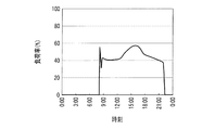
図7は、施設の熱負荷の時間的変化を示すグラフである。図7では、空調設備Aの定格処理熱量を100%とした場合の負荷率によって、施設Kの熱負荷を表している。
本実施形態では、放熱運転又は追掛運転を行う可能性のある時間帯(翌日の8時〜22時半)についてのみ熱負荷を算出するようにした。図7に示す例では、翌日の15時付近で施設K内の熱負荷が最大(負荷率:約58%)になっている。
FIG. 7 is a graph showing temporal changes in the thermal load of the facility. In FIG. 7, the heat load of the facility K is represented by the load factor when the rated processing heat amount of the air conditioning facility A is 100%.
In the present embodiment, the thermal load is calculated only for a time zone (from 8 to 22:30 on the next day) in which the heat radiation operation or the follow-up operation may be performed. In the example shown in FIG. 7, the heat load in the facility K is maximum (load factor: about 58%) around 15:00 on the next day.
図5のステップS1022においてコントローラ400は、消費エネルギ予測部423によって、熱負荷等に基づき空調設備Aの消費エネルギを各時間帯に関して予測する(消費エネルギ予測ステップ)。
ステップS1023においてコントローラ400は、需要電力予測部424によって、負荷装置の需要電力Pdemを各時間帯に関して予測する(需要電力予測ステップ)。
すなわち、コントローラ400は、ステップS1022で算出した消費エネルギに対応する電力値と、電力消費パターンDB411(図2参照)に格納されている電力消費パターンと、を足し合わせることで需要電力Pdemを算出する。換言すると、コントローラ400は、空調設備Aの需要電力と、空調設備A以外の機器の需要電力と、を足し合わせることによって、前記した負荷装置の需要電力Pdemを算出する。
In step S1022 of FIG. 5, the
In step S1023, the
That is, the
図8は、負荷装置の需要電力の時間的変化を示すグラフであり、翌日に蓄熱運転・放熱運転を行わないと仮定した場合での需要電力Pdemを表している。図8に示す例では、13時半〜18時付近において需要電力Pdemが供給可能電力Psup(5kW)を超えている。したがって、このような事態を回避するように空調設備の運転スケジュールを設定し、蓄熱運転・放熱運転によって電力平準化を図ることが要請される。 FIG. 8 is a graph showing a temporal change in the demand power of the load device, and represents the demand power P dem when it is assumed that the heat storage operation and the heat radiation operation are not performed on the next day. In the example illustrated in FIG. 8, the demand power P dem exceeds the suppliable power P sup (5 kW) in the vicinity of 13:30 to 18:00. Therefore, it is required to set an operation schedule of the air conditioning equipment so as to avoid such a situation, and to achieve power leveling by heat storage operation / heat radiation operation.
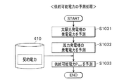
次に、図3のステップS103においてコントローラ400は、翌日の24時間を分割した複数の時間帯(例えば、1時間毎)に関して供給可能電力Psupを予測する。図6は、供給可能電力の予測処理の流れを示すフローチャートである。
ステップS1031においてコントローラ400は、発電電力予測部425によって、太陽光発電機G1の発電電力を各時間帯に関して予測する。当該処理には、ステップS101で取得した気温予測値及び日射量予測値が用いられる。
ステップS1032においてコントローラ400は、発電電力予測部425によって、風力発電機G2の発電電力を各時間帯に関して予測する。当該処理には、ステップS101で取得した風速予測値が用いられる。
Next, in step S103 of FIG. 3, the
In step S1031, the
In step S1032, the
ステップS1033においてコントローラ400は、負荷装置への供給可能電力Psupを予測する。すなわち、コントローラ400は、ステップS1031,S1032で算出した各発電電力の値と、記憶部410に格納されている契約電力の値と、を足し合わせることで、翌日の各時間帯における供給可能電力Psupを算出する。
図3のステップS104においてコントローラ400は、値n=1を設定する。これによって、時刻(t1+(n−1)Δt)〜時刻(t1+nΔt)で表される翌日の時間帯が指定される。前記した時刻t1は、例えば、蓄熱運転の終了時刻である翌日の午前7時であり、予め設定されている。
また、必要蓄熱量Q1の初期値としてゼロを設定する。必要蓄熱量Q1は、需要電力Pdemが供給可能電力Psupを超える領域の電力量(図8の斜線部分)を打ち消すために、蓄熱槽202に蓄えられる冷熱量である。
前記した値n及び必要蓄熱量Q1は、ステップS105〜S110の処理を行うたびに逐次更新される(S108、S110)。
In step S104 of FIG. 3, the
Moreover, zero is set as an initial value of the necessary heat storage amount Q1. The necessary heat storage amount Q1 is the amount of cold energy stored in the
The above-described value n and the necessary heat storage amount Q1 are sequentially updated every time the processes of steps S105 to S110 are performed (S108, S110).
ステップS105においてコントローラ400は、ステップS104で指定した時間帯に関して、負荷装置の需要電力Pdemが供給可能電力Psupよりも大きいか否かを判定する。需要電力Pdemが供給可能電力Psupよりも大きい場合(S105→Yes)、コントローラ400の処理はステップS106に進む。この場合において仮に蓄熱運転・放熱運転を行わないとすると、翌日の時刻t1〜(t1+Δt)で需要電力Pdemが供給可能電力Psupを超える可能性が高い。
一方、需要電力Pdemが供給可能電力Psup以下である場合(S105→No)、コントローラ400の処理はステップS109に進む。
In step S105, the
On the other hand, when the demand power P dem is equal to or less than the suppliable power P sup (S105 → No), the process of the
ステップS106においてコントローラ400は、需要電力Pdemから供給可能電力Psupを減算することによって超過電力ΔPを算出する。
ステップS107においてコントローラ400は、ステップS106で算出した超過電力ΔPに対応する蓄熱量ΔQを算出する。すなわち、コントローラ400は、超過電力ΔP×所定時間Δtで算出される電力量を打ち消すために必要となる蓄熱量ΔQを算出する。この蓄熱量ΔQは、空調設備Aを構成する機器の仕様情報、外気湿球温度等に基づいて算出される。
In step S106, the
In step S107, the
ステップS108においてコントローラ400は、前回までに積算(積分)した必要蓄熱量Q1に、ステップS107で算出した蓄熱量ΔQを足し合わせることで必要蓄熱量Q1を更新する。なお、n=1の場合、コントローラ400は、必要蓄熱量Q1の初期値ゼロ(S104)に蓄熱量ΔQを足し合わせることで必要蓄熱量Q1を更新する。
In step S108, the
ステップS109においてコントローラ400は、n=kであるか否かを判定する。なお、自然数kは、予め設定された値であり、必要蓄熱量Q1の予測対象となる時間帯の終端(例えば、翌々日の午前0時)に対応している。
n<kである場合(S109→No)、コントローラ400の処理はステップS110に進む。この場合、気象情報の予測対象となる時間帯のうちステップS105〜S108の処理が行われていないものが存在する。
In step S109, the
If n <k (S109 → No), the process of the
ステップS110においてコントローラ400は、値nをインクリメントしてステップS105の処理に進む。例えば、n=2の場合には、翌日の時刻(t1+Δt)〜(t1+2Δt)の時間帯の蓄熱量ΔQが算出され(S107)、前回までの必要蓄熱量Q1に足し合わされる(S108)。
一方、n=kである場合(S109→Yes)、コントローラ400の処理は図4のステップS111に進む。
In step S110, the
On the other hand, if n = k (S109 → Yes), the process of the
ステップS111においてコントローラ400は、ステップS108で最終的に更新された必要蓄熱量Q1を記憶部410から読み出して取得する。前記したように、必要蓄熱量Q1は、需要電力Pdemが供給可能電力Psupを超える領域の電力量を打ち消すために必要となる冷熱量である。
In step S111, the
ステップS112においてコントローラ400は、値m=1を設定する。ここで、値mは、ステップS113〜S119の処理を繰り返すたびに逐次インクリメントされる自然数である。また、コントローラ400は、ステップS116,S118で用いる暫定的な蓄熱量Qproとして必要蓄熱量Q1を設定する。
In step S112, the
ステップS113においてコントローラ400は、蓄熱運転を行う際の外気湿球温度を算出する。すなわち、コントローラ400はステップS101で取得した気象情報に基づいて、蓄熱運転の終了時刻(例えば、翌日の午前7時)からmΔtだけ遡った外気湿球温度を算出する。前記した所定時間Δtは予め設定されている。なお、前記した蓄熱運転の終了時刻は、予め設定されている。
In step S113, the
本実施形態では、夜間・早朝に行う蓄熱運転の終了時刻を固定し、開始時刻を変化させることで蓄熱運転を行う時間を調整するようにした。つまり、ステップS113〜S119では、蓄熱運転の終了時刻から時間的に遡るように演算処理が実行される。これによって、蓄熱運転の終了時刻を最大限に遅らせて蓄熱槽202から外気への放熱を抑制し、システム全体のエネルギ効率を高めることができる。
In this embodiment, the end time of the heat storage operation performed at night / early morning is fixed, and the time for performing the heat storage operation is adjusted by changing the start time. That is, in steps S113 to S119, the calculation process is executed so as to go back in time from the end time of the heat storage operation. Thereby, the end time of the heat storage operation can be delayed as much as possible to suppress the heat radiation from the
ステップS114においてコントローラ400は、ステップS113で算出した外気湿球温度に基づいて、空調設備Aを運転する際の負荷率を設定する。図9は、空調設備Aの負荷率とCOPとの関係を示す特性図である。図9に示すように、外気湿球温度を一定とした場合、冷凍機201を稼働させる際の負荷率に応じて空調設備Aの成績係数であるCOP(つまり、エネルギ消費効率)が変化する。
In step S114, the
コントローラ400は、図2に示す記憶部410の負荷特性DB412を参照し、蓄熱運転時の外気湿球温度に基づいてCOPを最大にするように、空調設備Aの負荷率を設定する(S114)。例えば、図9に示すように、m=1(S112)に対応する時間帯の外気湿球温度が25℃WBである場合、コントローラ400はCOPが最大値Y1になる負荷率72%となるように運転スケジュールを設定する。これによって、蓄熱運転に要する空調設備Aの消費電力を低減し、年間の電気コストを削減できる。
The
なお、熱源シミュレータを用いてステップS114の処理を実行してもよいし、本実施形態のように負荷特性(図9参照)をデータベースとして予め記憶部410に格納しておいてもよい。
In addition, you may perform the process of step S114 using a heat source simulator, and you may store the load characteristic (refer FIG. 9) in the memory |
図4のステップS115においてコントローラ400は、ステップS114で算出した負荷率で所定時間Δtだけ冷凍機201を運転した場合の蓄熱量ΔQ2を算出する。
ステップS116においてコントローラ400は、ステップS115で算出した蓄熱量ΔQ2を蓄熱量Qproから減算することで、残りの蓄熱量Qremを算出する。なお、初回の計算では蓄熱量Qproとして必要蓄熱量Q1が用いられるが(S112)、後記するステップS118で蓄熱量Qproの値が逐次更新される(減少していく)。
In step S115 of FIG. 4, the
In step S116, the
ステップS117においてコントローラ400は、必要蓄熱量Q1が満たされたか否かを判定する。つまり、コントローラ400は、ステップS116で算出した残りの蓄熱量Qremがゼロ以下であるか否かを判定する。
In step S117, the
必要蓄熱量Q1が満たされていない場合(S117→No)、コントローラ400の処理はステップS118に進む。
ステップS118においてコントローラ400は、暫定的な蓄熱量QproとしてステップS116で算出した残りの蓄熱量Qremを代入する。次に、ステップS119においてコントローラ400は、値mをインクリメントする。
When the necessary heat storage amount Q1 is not satisfied (S117 → No), the process of the
In step S118, the
一方、必要蓄熱量Q1が満たされている場合(S117→Yes)、コントローラ400の処理はステップS120に進む。この時点における値mと、所定時間Δtと、を乗算して得られる値(mΔt)が、翌日の蓄熱運転の継続時間になる。
例えば、所定時間Δtが1時間であり、値mが4の状態で必要蓄熱量Q1が満たされた場合、コントローラ400は翌日に4時間の(例えば、午前3時〜7時の時間帯で)蓄熱運転を行うように運転スケジュールを設定する。
On the other hand, when the necessary heat storage amount Q1 is satisfied (S117 → Yes), the process of the
For example, when the required heat storage amount Q1 is satisfied in a state where the predetermined time Δt is 1 hour and the value m is 4, the
ステップS120においてコントローラ400は、スケジュール設定部427によって、空調設備Aの運転スケジュールを設定する(スケジュール設定ステップ)。ここで、運転スケジュールの設定とは、翌日における空調設備Aの運転モード、及び、各運転モードの切替時刻の設定を意味している。
通常、夜間の電力価格は、昼間の電力価格よりも安い。したがって、コントローラ400は、安価な夜間電力を用いて蓄熱運転し、昼間に追掛運転及び放熱運転を実行するように運転スケジュールを設定する。
In step S120, the
Usually, the nighttime power price is lower than the daytime power price. Therefore, the
また、コントローラ400は、負荷装置の需要電力Pdemが供給可能電力Psupを超える領域の電力量(図8に示す斜線部分の面積)を算出し、少なくとも当該電力量を打ち消すように空調設備Aの運転スケジュールを設定する。
Further, the
図10は、空調設備にかかる熱負荷と、負荷装置の需要電力と、の関係を示す説明図である。なお、空調設備Aの定格処理熱量を100%とした負荷率で空調設備Aの熱負荷を表している。また、3つの相異なる外気湿球温度T1,T2,T3(T1<T2<T3)について、負荷率と需要電力との関係を図示した。
図10に示す点αの熱負荷(負荷率58%)は、図7に示すグラフの15時付近における熱負荷に対応し、点αの需要電力(5.3kW)は、図8に示すグラフの15時付近における需要電力に対応している。点βは、負荷装置の需要電力が供給可能電力Psupに等しい状態(負荷率38%、需要電力5kW)に対応している。
FIG. 10 is an explanatory diagram showing the relationship between the heat load applied to the air conditioning equipment and the demand power of the load device. In addition, the heat load of the air conditioning equipment A is represented by a load factor where the rated processing heat amount of the air conditioning equipment A is 100%. Further, the relationship between the load factor and the demand power is illustrated for three different outdoor wet bulb temperatures T1, T2, and T3 (T1 <T2 <T3).
The thermal load at point α shown in FIG. 10 (load factor 58%) corresponds to the thermal load around 15:00 in the graph shown in FIG. 7, and the demand power at point α (5.3 kW) is the graph shown in FIG. Corresponds to the power demand around 15:00. The point β corresponds to a state where the demand power of the load device is equal to the suppliable power Psup (load rate 38%,
前記したように、需要電力Pdemが供給可能電力Psupを超える時間帯(13時半〜18時付近:図8参照)で放熱運転を行うことで、空調設備Aの状態を図10に示す点αから点βに移行させることができる。つまり、図10に示す幅ΔXだけ空調設備Aの負荷率を低減させることで、需要電力Pdemを供給可能電力Psup以下に抑えることができる。
なお、蓄熱運転時に冷凍機201で生成する冷熱量に余裕を持たせ、放熱運転時の冷水流量を適宜調整することで、空調設備Aの状態を点γに移行させてもよい。
As described above, the state of the air conditioning equipment A is shown in FIG. 10 by performing the heat radiation operation in the time zone where the demand power P dem exceeds the suppliable power P sup (around 13:30 to 18:00: see FIG. 8). It is possible to shift from the point α to the point β. That is, by reducing the load factor of the air conditioning equipment A by the width ΔX shown in FIG. 10, the demand power P dem can be suppressed below the suppliable power P sup .
It should be noted that the state of the air conditioning equipment A may be shifted to the point γ by giving a margin to the amount of cold heat generated by the refrigerator 201 during the heat storage operation and appropriately adjusting the flow rate of cold water during the heat radiation operation.
(2.運転スケジュールの実行)
次に、運転スケジュールに沿った空調設備Aの動作について、図11を参照しつつ簡単に説明する。
図11は、各運転モードを実行した場合における空調設備の熱負荷の時間的変化を示すグラフである。なお、空調設備Aの定格処理熱量を100%とした負荷率で空調設備Aの熱負荷を表している。また、図11に示す破線は、図7に示す熱負荷(負荷率)に対応している。
(2. Execution of operation schedule)
Next, operation | movement of the air conditioning equipment A according to an operation schedule is demonstrated easily, referring FIG.
FIG. 11 is a graph showing temporal changes in the heat load of the air conditioning equipment when each operation mode is executed. In addition, the heat load of the air conditioning equipment A is represented by a load factor where the rated processing heat amount of the air conditioning equipment A is 100%. Moreover, the broken line shown in FIG. 11 respond | corresponds to the thermal load (load factor) shown in FIG.
(蓄熱運転)
蓄熱運転の開始時刻(例えば、午前3時:図11参照)になった場合、コントローラ400は、制御信号生成部428によって蓄熱運転を実行する。すなわち、コントローラ400は、図1に示す冷凍機201及び冷却塔101を割安の夜間電力で運転し、冷却水ポンプ102を運転する。これによって、配管p1,p2を介して冷却水が循環する。
(Heat storage operation)
When the start time of the heat storage operation is reached (for example, 3:00 am: see FIG. 11), the
また、コントローラ400は第一冷水ポンプ203を停止させ、第二冷水ポンプ204を駆動させる。そうすると、冷凍機201から流出する低温の冷水は、配管q1を介して蓄熱槽202の下部に流入する。また、蓄熱槽202の上部に貯留されている比較的高温の冷水は、配管q4を介して冷凍機201に圧送される。このようにして、冷凍機201で生成された冷熱が蓄熱槽202に蓄えられる。
この場合、比較的高温の冷水を冷却するため、冷凍機201を運転する際のエネルギ効率を高くすることができる。
In addition, the
In this case, since relatively high-temperature cold water is cooled, energy efficiency when operating the refrigerator 201 can be increased.
蓄熱運転が進むにつれて、蓄熱槽202に貯留された冷水のうち、よく冷やされた冷水と比較的高温である冷水との境界面が上昇していく。蓄熱運転の終了時刻(例えば、午前7時:図11参照)になった場合、コントローラ400は蓄熱運転を終了する。
As the heat storage operation proceeds, the boundary surface between the chilled water stored in the
(追掛運転)
次に、追掛運転の開始時刻(例えば、午前8時:図11参照)になった場合、コントローラ400は、制御信号生成部428によって追掛運転を実行する。すなわち、コントローラ400は、図1に示す冷凍機201及び冷却塔101を運転し、冷却水ポンプ102を運転する。また、コントローラ400は、第一冷水ポンプ203及び第二冷水ポンプ204を運転する。
(Chase operation)
Next, when the start time of the follow-up operation is reached (for example, 8:00 am: see FIG. 11), the
そうすると、冷凍機201で冷やされた冷水が配管q1、蓄熱槽202の下部領域、及び配管q2を介して室内機205に流入し、室内空気が冷やされる。追掛運転の終了時刻(例えば、13時:図11参照)になった場合、コントローラ400は追掛運転を終了する。
If it does so, the cold water cooled with the refrigerator 201 will flow into the
(放熱運転)
次に、放熱運転の開始時刻(例えば、13時:図11参照)になった場合、コントローラ400は、制御信号生成部428によって放熱運転を実行する。すなわち、コントローラ400は、図1に示す冷凍機201、冷却塔101、及び冷却水ポンプ102を停止させる。また、コントローラ400は、第一冷水ポンプ203を運転し、第二冷水ポンプ204を停止させる。
(Heat dissipation operation)
Next, when the start time of the heat radiation operation is reached (for example, 13:00: see FIG. 11), the
そうすると、蓄熱槽202の下部から流出する低温の冷水は、配管q2を介して室内機205に流入し、室内空気が冷やされる。ちなみに、放熱によるエネルギロスを抑えるため、蓄熱槽202の下部に貯留された低温の冷水を放熱運転で使い切ることが好ましい。放熱運転の終了時刻(例えば、21時:図11参照)になった場合、コントローラ400は放熱運転を終了する。
If it does so, the low temperature cold water which flows out out of the lower part of the
なお、放熱運転している間も継続して冷凍機201を運転し、蓄熱槽202及び冷凍機201から室内機205に冷水を供給する放熱・追掛運転を行うようにしてもよい。
図11に示す例では、18時付近においてコントローラ400は、一時的に放熱運転を中断している。これは、図8に示す18時付近において、需要電力Pdemが供給可能電力Psupを一時的に下回ったからである。なお、このような需要電力の一時的な変動を無視して放熱運転を継続するようにしてもよい。
放熱運転を終了した後、図11の21時〜22時半においてコントローラ400は、追掛運転を再度実行し、処理を終了する。
Note that the refrigerator 201 may be continuously operated during the heat dissipation operation, and the heat dissipation / chase operation for supplying cold water from the
In the example shown in FIG. 11, the
After finishing the heat radiation operation, the
<効果>
本実施形態係る空調制御システムSによれば、コントローラ400は、比較的安価な夜間電力で蓄熱運転を実行し、昼間に追掛運転・放熱運転を含む運転モードを実行する。これによって、空調設備Aの電力コストを従来よりも削減できる。
また、コントローラ400は、昼間に比べて電力需要が少ない夜間に蓄熱運転し、電力需要が多くなる昼間に放熱運転することで空調設備Aの処理負荷を低減する。これによって、空調設備Aを含む負荷装置の需要電力を平準化できる。
<Effect>
According to the air conditioning control system S according to the present embodiment, the
Moreover, the
また、コントローラ400は、予測した需要電力Pdemが供給可能電力Psupを超えた領域の電力量を少なくとも打ち消すように放熱運転を実行する。これによって、買電電力が契約電力を上回ることを防止し、年間を通した電力コスト(基本料金及び従量料金)を削減できる。
In addition, the
また、コントローラ400は、需要電力Pdemが供給可能電力Psupを超えたぶんの超過電力ΔPに対応する蓄熱量ΔQを積算することで必要蓄熱量Q1を算出する(S107,S108:図3参照)。つまり、冷凍機201によって、需要電力Pdemが供給可能電力Psupを超えないために最低限必要な冷熱を生成する。仮に、過大な冷熱が蓄熱槽202に貯留された場合、放熱に伴うエネルギロスでかえって電力コストがかさむことがある。本実施形態によれば、蓄熱槽202に蓄える冷熱をある程度抑制することで、放熱に伴うエネルギロスを低減できる。
なお、前記した最低限必要な冷熱に所定の余裕を持たせるように冷凍機201を運転し、蓄熱槽202に蓄える冷熱を適宜調整してもよい。
Further, the
It should be noted that the refrigerator 201 may be operated so as to give a predetermined margin to the above-described minimum necessary cold heat, and the cold heat stored in the
また、蓄熱運転時の運転スケジュールを設定する際、コントローラ400は負荷特性DB412(図2参照)を参照し、冷凍機201のCOPが最大となるように負荷率を設定する(S114:図4参照)。これによって、高いエネルギ消費効率で蓄熱運転を実行できるため、空調設備Aに要する電力コストを従来よりも削減できる。
Further, when setting the operation schedule during the heat storage operation, the
≪第2実施形態≫
第2実施形態に係る空調制御システムS1は、負荷装置に電力供給可能な電源設備として、内燃力発電機G3(図12参照)と、蓄電池Bと、を追加した点が第1実施形態と異なるが、その他の点は第1実施形態と同様である。したがって、当該異なる部分について説明し、第1実施形態と重複する部分については説明を省略する。
<< Second Embodiment >>
The air conditioning control system S1 according to the second embodiment is different from the first embodiment in that an internal combustion power generator G3 (see FIG. 12) and a storage battery B are added as power supply equipment that can supply power to the load device. However, other points are the same as in the first embodiment. Therefore, the said different part is demonstrated and description is abbreviate | omitted about the part which overlaps with 1st Embodiment.
図12は、本発明の第2実施形態に係る空調制御システムを含む構成図である。
内燃力発電機G3は、ガスエンジン発電機、ディーゼルエンジン発電機等であり、負荷装置に対して電力供給可能に接続されている。内燃力発電機G3は、外部からの操作に応じてエンジンを駆動し、発電するように構成されている。
蓄電池Bは、鉛蓄電池、リチウムイオン蓄電池等であり、コントローラ400からの指令に応じて太陽光発電機G1及び風力発電機G2で発電された電力を充電したり、負荷装置に放電したりするように構成されている。
FIG. 12 is a configuration diagram including an air conditioning control system according to the second embodiment of the present invention.
The internal combustion power generator G3 is a gas engine generator, a diesel engine generator, or the like, and is connected so as to be able to supply power to the load device. The internal combustion power generator G3 is configured to generate power by driving the engine in accordance with an external operation.
The storage battery B is a lead storage battery, a lithium ion storage battery, or the like, and charges the power generated by the solar power generator G1 and the wind power generator G2 or discharges it to the load device according to a command from the
なお、図12では図示を省略したが、内燃力発電機G3及び蓄電池Bにはそれぞれ、直流/交流変換や電力変動補償を実行するPCSが接続されている。 Although not shown in FIG. 12, each of the internal combustion power generator G3 and the storage battery B is connected to a PCS that performs DC / AC conversion and power fluctuation compensation.
<空調制御システムの動作>
図13は、コントローラが実行する処理の流れを示すフローチャートである。
第1実施形態で説明したステップS101〜S111(図3、図4参照)の処理を実行した後、図13のステップS201においてコントローラ400は、蓄熱槽202の蓄熱容量QCで、需要電力Pdemを供給可能電力Psup以下に抑えられるかどうかを判定する。つまり、コントローラ400は、ステップS111で取得した必要蓄熱量Q1が、蓄熱槽202の蓄熱容量QC以下であるか否かを判定する。なお、蓄熱槽202の蓄熱容量QCは予め記憶部410に格納されている。
<Operation of air conditioning control system>
FIG. 13 is a flowchart showing the flow of processing executed by the controller.
Step S101~S111 (see FIGS. 3 and 4) described in the first embodiment after performing the process of the
蓄熱槽202の蓄熱容量QCで足りる場合(S201→Yes)、コントローラ400は、ステップS112〜S120(図4参照)の処理を実行した後、処理を終了する(END)。
一方、蓄熱槽202の蓄熱容量QCでは足りない場合(S201→No)、コントローラ400の処理はステップS202に進む。
If sufficient heat storage capacity Q C of the heat storage tank 202 (S201 → Yes), the
On the other hand, if insufficient in heat storage capacity Q C of the heat storage tank 202 (S201 → No), processing of the
ステップS202においてコントローラ400は、蓄熱運転を行う際の蓄熱量を、蓄熱槽202の蓄熱容量QCとして設定する。つまり、コントローラ400は、蓄熱運転時に最大限の冷熱を蓄えるように蓄熱量を設定する。
ステップS203においてコントローラ400は、空調設備Aの運転スケジュールを設定する。例えば、コントローラ400は、負荷特性DB412(図2参照)を参照し、蓄熱運転時の外気湿球温度に基づいてCOPを最大とするように空調設備Aの負荷率を設定する。なお、蓄熱可能な時間帯(例えば、午前0時〜7時)の中で最大限の冷熱を蓄えることを優先し、空調設備Aの負荷率を高めに設定してもよい。
In step S203, the
ステップS204においてコントローラ400は、不足分の電力量を算出する。つまり、コントローラ400は、ステップS111で取得した必要蓄熱量Q1から、蓄熱槽202の蓄熱容量QCを減算した値に対応する電力量を算出する。この電力量は、空調設備Aの仕様情報、翌日の外気湿球温度等に基づいて算出される。
ステップS205においてコントローラ400は、内燃力発電機G3の運転スケジュールを設定する。すなわち、コントローラ400は、負荷装置の需要電力Pdemが供給可能電力Psupを超える時間帯において、内燃力発電機G3から空調設備Aに電力供給するように、内燃力発電機G3の運転スケジュールを設定する。
In step S <b> 204, the
In step S205, the
ステップS206においてコントローラ400は、内燃力発電機G3の発電電力で足りるかどうかを判定する。すなわち、コントローラ400は、内燃力発電機G3を用いて負荷装置に電力供給する際、需要電力Pdemが供給可能電力Psupを超える時間帯があるかどうかを判定する。
内燃力発電機G3の発電電力で足りる場合(S206→Yes)、コントローラ400は処理を終了する(END)。一方、内燃力発電機G3の発電電力では足りない場合(S206→No)、コントローラ400の処理はステップS207に進む。
In step S206, the
When the power generated by the internal combustion power generator G3 is sufficient (S206 → Yes), the
ステップS207においてコントローラ400は、蓄電池Bを充放電するための運転スケジュールを設定する。すなわち、コントローラ400は、負荷装置の需要電力Pdemが供給可能電力Psupを超える時間帯において蓄電池Bから空調設備Aに放電するように、蓄電池Bの運転スケジュールを設定する。なお、蓄電池Bから空調設備Aに放電する時間帯において、内燃力発電機G3からも空調設備Aに電力供給される。
In step S207, the
<効果>
本実施形態によれば、コントローラ400は、翌日の需要電力に応じて、内燃力発電機G3及び蓄電池Bの運転スケジュールを設定する。これによって、空調設備Aによる蓄熱運転・放熱運転のみでは需要電力Pdemが供給可能電力Psupを超える場合でも、内燃力発電機G3(及び蓄電池B)からの供給電力によって、その不足分を補うことができる。
したがって、負荷装置を稼働させるための買電電力が契約電力を超える事態を確実に回避し、年間を通じた電気コストを従来よりも削減できる。
<Effect>
According to this embodiment, the
Therefore, it is possible to reliably avoid a situation where the purchased power for operating the load device exceeds the contracted power, and to reduce the electric cost throughout the year compared to the conventional case.
≪変形例≫
以上、本発明に係る空調制御システムS,S1について各実施形態により説明したが、本発明はこれらの記載に限定されるものではなく、種々の変更を行うことができる。
例えば、各実施形態では、蓄熱運転時においてCOPが最大となるように空調設備Aの負荷率を設定する場合について説明したが、これに限らない。当該方法で設定される負荷率で蓄熱運転し続けた場合に冷熱量が足りず、需要電力Pdemが供給可能電力Psupを補えないこともあり得る。この場合に高めの負荷率で蓄熱運転し、その後の放熱運転によって昼間の需要電力Pdemを抑えるようにしてもよい。
≪Modification≫
As mentioned above, although air-conditioning control system S and S1 concerning the present invention were explained by each embodiment, the present invention is not limited to these statements and can change variously.
For example, in each embodiment, although the case where the load factor of air-conditioning equipment A was set so that COP might become the maximum at the time of heat storage operation was demonstrated, it is not restricted to this. When the heat storage operation is continued at the load factor set by this method, the amount of cold energy is insufficient, and the demand power P dem may not be able to supplement the suppliable power P sup . In this case, the heat storage operation may be performed at a higher load factor, and the daytime demand power P dem may be suppressed by the subsequent heat radiation operation.
また、各実施形態では、自然エネルギを用いた発電機として太陽光発電機G1及び風力発電機G2を用いる場合について説明したが、これらのうち一方又は両方を省略してもよい。また、地熱発電機といった他の種類の発電機を追加してもよい。 Moreover, although each embodiment demonstrated the case where the solar power generator G1 and the wind power generator G2 were used as a generator using natural energy, you may abbreviate | omit one or both. Also, other types of generators such as geothermal generators may be added.
また、各実施形態では、冷凍機201(熱源機)で冷熱を生成する場合について説明したが、これに限らない。すなわち、周知のヒートポンプサイクル等を利用することで冷凍機201において水に温熱を与えて蓄熱槽202に温水を貯留したり、配管q1,q2を介して室内機205に温水を圧送したりしてもよい。
Moreover, although each embodiment demonstrated the case where cold energy was produced | generated with the refrigerator 201 (heat source machine), it is not restricted to this. That is, by using a well-known heat pump cycle or the like, warm water is stored in the regenerator 201 to store hot water in the
また、各実施形態では、一次側空調設備を循環する冷媒と、二次側空調設備を循環する冷媒と、がともに水である場合について説明したが、これに限らない。すなわち、冷熱を搬送可能であれば、水以外の冷媒を用いてもよい。 Moreover, although each embodiment demonstrated the case where the refrigerant | coolant which circulates a primary side air conditioner and the refrigerant | coolant which circulates a secondary side air conditioner were both water, it does not restrict to this. That is, a refrigerant other than water may be used as long as cold heat can be conveyed.
また、第2実施形態では、内燃力発電機G3及び蓄電池Bが負荷装置に対して電力供給可能に接続される場合について説明したが、これらのうち一方を省略してもよい。また、蓄電池B(図12参照)よりも内燃力発電機G3を優先的に駆動する場合について説明したが、当該優先順位を入れ替えてもよい。
また、第2実施形態で説明した蓄電池Bに代えて、又は、蓄電池Bとともに電気二重層キャパシタ等のキャパシタを用いて負荷装置に電力供給してもよい。
Moreover, although 2nd Embodiment demonstrated the case where the internal combustion power generator G3 and the storage battery B were connected so that electric power could be supplied with respect to a load apparatus, you may abbreviate | omit one of these. Moreover, although the case where the internal combustion power generator G3 is preferentially driven over the storage battery B (see FIG. 12) has been described, the priority order may be switched.
Moreover, it may replace with the storage battery B demonstrated in 2nd Embodiment, or may supply electric power to a load apparatus using capacitors, such as an electric double layer capacitor, with the storage battery B. FIG.
S,S1 空調制御システム
101 冷却塔(負荷装置)
102 冷却水ポンプ(負荷装置)
201 冷凍機(熱源機、負荷装置)
202 蓄熱槽
203 第一冷水ポンプ(負荷装置)
204 第二冷水ポンプ(負荷装置)
205 室内機(負荷装置)
205a 室内熱交換器
205b 室内ファン(負荷装置)
300 気象情報サーバ
400 コントローラ
410 記憶部
420 演算処理部
421 気象情報取得部
422 熱負荷予測部
423 消費エネルギ予測部
424 需要電力予測部
425 発電電力予測部
426 供給可能電力予測部
427 スケジュール設定部
428 制御信号生成部
A 空調設備
G1 太陽光発電機
G2 風力発電機
G3 内燃力発電機
B 蓄電池
K 施設
R1 照明装置(負荷装置)
R2 業務用パソコン(負荷装置)
S, S1 Air
102 Cooling water pump (load device)
201 Refrigerator (heat source machine, load device)
202
204 Second cold water pump (load device)
205 Indoor unit (load device)
205a
DESCRIPTION OF
R2 Business PC (load device)
Claims (6)
前記気象情報取得部によって取得される前記気象情報に基づいて、施設内の熱負荷を予測する熱負荷予測部と、
前記熱負荷予測部によって予測される前記熱負荷に基づき、冷凍機で冷やされて蓄熱槽に貯留される冷媒によって前記施設を空調可能な空調設備の消費エネルギを予測する消費エネルギ予測部と、
前記消費エネルギ予測部によって予測される前記消費エネルギに基づいて、前記空調設備を含む負荷装置の需要電力を予測する需要電力予測部と、
前記需要電力予測部によって予測される前記需要電力に基づいて、前記空調設備の運転スケジュールを設定するスケジュール設定部と、
前記スケジュール設定部によって設定される運転スケジュールに従って、前記蓄熱槽の冷媒に蓄熱する蓄熱運転と、前記蓄熱槽の冷媒と室内空気とを熱交換させる放熱運転と、含む複数の運転モードを実行するための制御信号を生成する制御信号生成部と、を備え、
前記スケジュール設定部は、
前記需要電力が、前記負荷装置に供給可能な電力である供給可能電力を超える領域の電力量を算出し、少なくとも当該電力量を打ち消すように前記空調設備の運転スケジュールを設定し、
予め設定されている前記蓄熱運転の終了予定時刻から所定時間ごとに時間を遡って、前記冷凍機の処理負荷の和を積算し、前記和が前記領域に相当する必要蓄熱量に達した時刻を前記蓄熱運転の開始予定時刻として設定し、さらに、前記領域に対応する時間帯を前記放熱運転の時間帯として設定すること
を特徴とする空調制御システム。 A weather information acquisition unit that acquires weather information including a temperature predicted value, a humidity predicted value, and a solar radiation amount predicted value from a weather information server that manages weather information;
Based on the weather information acquired by the weather information acquisition unit, a heat load prediction unit that predicts the heat load in the facility,
Based on the thermal load predicted by the thermal load prediction unit, an energy consumption prediction unit that predicts energy consumption of an air conditioning facility that can air-condition the facility with a refrigerant that is cooled in a refrigerator and stored in a heat storage tank;
Based on the energy consumption predicted by the energy consumption prediction unit, a power demand prediction unit that predicts the power demand of the load device including the air conditioning equipment;
Based on the demand power predicted by the demand power prediction unit, a schedule setting unit that sets an operation schedule of the air conditioning equipment;
In order to execute a plurality of operation modes including a heat storage operation for storing heat in the refrigerant in the heat storage tank and a heat radiation operation for exchanging heat between the refrigerant in the heat storage tank and room air according to the operation schedule set by the schedule setting unit. A control signal generator for generating a control signal of
The schedule setting unit,
Before Symbol demand power, the load device available power is capable of supplying power to calculate the amount of power in the region more than in, setting the air-conditioning systems operating schedule so as to cancel at least the amount of power,
Going back in time from the preset scheduled end time of the heat storage operation every predetermined time, integrating the sum of the processing loads of the refrigerator, and the time when the sum reaches the necessary heat storage amount corresponding to the region The air conditioning control system is set as a scheduled start time of the heat storage operation, and further, a time zone corresponding to the region is set as a time zone of the heat dissipation operation .
前記スケジュール設定部は、前記特性情報を参照し、蓄熱運転時の外気湿球温度に基づいて、前記空調設備のエネルギ消費効率を最大にするように、前記空調設備の負荷率を設定すること
を特徴とする請求項1に記載の空調制御システム。 A storage unit that stores characteristic information indicating a relationship between an outdoor wet bulb temperature, a load factor of the air conditioning equipment, and an energy consumption efficiency of the air conditioning equipment;
The schedule setting unit refers to the characteristic information, and sets the load factor of the air conditioning equipment so as to maximize the energy consumption efficiency of the air conditioning equipment based on the outdoor wet bulb temperature during the heat storage operation. The air conditioning control system according to claim 1, wherein
前記発電電力予測部によって予測される前記太陽光発電機の発電電力と、予め設定される買電電力の上限閾値と、の和をとることで、前記供給可能電力を予測する供給可能電力予測部と、を備えること
を特徴とする請求項1に記載の空調制御システム。 Based on the weather information, a generated power prediction unit that predicts the generated power of a solar generator that generates power by being irradiated with sunlight,
A suppliable power predicting unit that predicts the suppliable power by taking the sum of the generated power of the solar power generator predicted by the generated power predicting unit and a preset upper limit threshold of purchased power. The air conditioning control system according to claim 1, further comprising:
前記需要電力が前記供給可能電力を超える領域の電力量を打ち消すために必要な蓄熱量が前記蓄熱槽の蓄熱容量よりも大きい場合、その不足分を補うように、前記負荷装置に電力供給可能な内燃力発電機の運転スケジュールを設定すること
を特徴とする請求項1から請求項3のいずれか一項に記載の空調制御システム。 The schedule setting unit
When the amount of heat storage required to cancel the amount of power in the region where the demand power exceeds the suppliable power is larger than the heat storage capacity of the heat storage tank, power can be supplied to the load device so as to compensate for the shortage The operation schedule of an internal combustion power generator is set. The air conditioning control system according to any one of claims 1 to 3 .
前記需要電力が前記供給可能電力を超える領域の電力量を打ち消すために必要な蓄熱量が前記蓄熱槽の蓄熱容量よりも大きい場合、その不足分を補うように、前記負荷装置に電力供給可能な蓄電池の運転スケジュールを設定すること
を特徴とする請求項1から請求項3のいずれか一項に記載の空調制御システム。 The schedule setting unit
When the amount of heat storage required to cancel the amount of power in the region where the demand power exceeds the suppliable power is larger than the heat storage capacity of the heat storage tank, power can be supplied to the load device so as to compensate for the shortage air conditioning control system according to any one of claims 1 to 3, characterized in that to set the operation schedules of the battery.
前記気象情報取得ステップで取得される前記気象情報に基づいて、施設内の熱負荷を予測する熱負荷予測ステップと、
前記熱負荷予測ステップで予測される前記熱負荷に基づき、冷凍機で冷やされて蓄熱槽に貯留される冷媒によって前記施設を空調可能な空調設備の消費エネルギを予測する消費エネルギ予測ステップと、
前記消費エネルギ予測ステップで予測される前記消費エネルギに基づいて、前記空調設備を含む負荷装置の需要電力を予測する需要電力予測ステップと、
前記需要電力予測ステップで予測される前記需要電力に基づいて、前記空調設備の運転スケジュールを設定するスケジュール設定ステップと、
前記スケジュール設定ステップで設定される運転スケジュールに従って、前記蓄熱槽の冷媒に蓄熱する蓄熱運転と、前記蓄熱槽の冷媒と室内空気とを熱交換させる放熱運転と、含む複数の運転モードを実行するための制御信号を生成する制御信号生成ステップと、を含み、
前記スケジュール設定ステップにおいて、
前記需要電力が、前記負荷装置に供給可能な電力である供給可能電力を超える領域の電力量を算出し、少なくとも当該電力量を打ち消すように前記空調設備の運転スケジュールを設定し、
予め設定されている前記蓄熱運転の終了予定時刻から所定時間ごとに時間を遡って、前記冷凍機の処理負荷の和を積算し、前記和が前記領域に相当する必要蓄熱量に達した時刻を前記蓄熱運転の開始予定時刻として設定し、さらに、前記領域に対応する時間帯を前記放熱運転の時間帯として設定すること
を特徴とする空調制御方法。 A weather information acquisition step of acquiring weather information including a temperature predicted value, a humidity predicted value, and a solar radiation amount predicted value from a weather information server that manages the weather information;
Based on the weather information acquired in the weather information acquisition step, a heat load prediction step of predicting a heat load in the facility,
Based on the thermal load predicted in the thermal load prediction step, an energy consumption prediction step for predicting energy consumption of an air conditioning facility capable of air-conditioning the facility with a refrigerant cooled in a refrigerator and stored in a heat storage tank;
Based on the energy consumption predicted in the energy consumption prediction step, a power demand prediction step for predicting the power demand of the load device including the air conditioning equipment;
A schedule setting step of setting an operation schedule of the air conditioning equipment based on the demand power predicted in the demand power prediction step;
In order to execute a plurality of operation modes including a heat storage operation for storing heat in the refrigerant in the heat storage tank and a heat radiation operation for exchanging heat between the refrigerant in the heat storage tank and room air according to the operation schedule set in the schedule setting step. A control signal generation step of generating a control signal of
In the schedule setting step ,
Before Symbol demand power, the load device available power is capable of supplying power to calculate the amount of power in the region more than in, setting the air-conditioning systems operating schedule so as to cancel at least the amount of power,
Going back in time from the preset scheduled end time of the heat storage operation every predetermined time, integrating the sum of the processing loads of the refrigerator, and the time when the sum reaches the necessary heat storage amount corresponding to the region The air-conditioning control method is set as a scheduled start time of the heat storage operation, and further, a time zone corresponding to the region is set as a time zone of the heat dissipation operation .
Priority Applications (2)
| Application Number | Priority Date | Filing Date | Title |
|---|---|---|---|
| JP2013196946A JP6282071B2 (en) | 2013-09-24 | 2013-09-24 | Air conditioning control system and air conditioning control method |
| PCT/JP2014/070341 WO2015045619A1 (en) | 2013-09-24 | 2014-08-01 | Air-conditioning control system and air-conditioning control method |
Applications Claiming Priority (1)
| Application Number | Priority Date | Filing Date | Title |
|---|---|---|---|
| JP2013196946A JP6282071B2 (en) | 2013-09-24 | 2013-09-24 | Air conditioning control system and air conditioning control method |
Publications (2)
| Publication Number | Publication Date |
|---|---|
| JP2015064120A JP2015064120A (en) | 2015-04-09 |
| JP6282071B2 true JP6282071B2 (en) | 2018-02-21 |
Family
ID=52742775
Family Applications (1)
| Application Number | Title | Priority Date | Filing Date |
|---|---|---|---|
| JP2013196946A Active JP6282071B2 (en) | 2013-09-24 | 2013-09-24 | Air conditioning control system and air conditioning control method |
Country Status (2)
| Country | Link |
|---|---|
| JP (1) | JP6282071B2 (en) |
| WO (1) | WO2015045619A1 (en) |
Families Citing this family (14)
| Publication number | Priority date | Publication date | Assignee | Title |
|---|---|---|---|---|
| CN105509230A (en) * | 2015-12-15 | 2016-04-20 | 天脉聚源(北京)传媒科技有限公司 | Control method and device of intelligent equipment |
| KR102437291B1 (en) | 2016-01-06 | 2022-08-30 | 삼성전자 주식회사 | Apparatus and method for automatic control of temperature |
| CN106091249B (en) * | 2016-06-13 | 2019-07-09 | 珠海格力电器股份有限公司 | Cooler compressor electric heating controlling method and device |
| CN106849064B (en) * | 2017-03-01 | 2020-08-28 | 上海海能信息科技有限公司 | Regional power grid load prediction management system based on meteorological data |
| CN106849365A (en) * | 2017-03-23 | 2017-06-13 | 上海海能信息科技有限公司 | A kind of grid dispatching management system based on equipment on-line monitoring |
| WO2018211679A1 (en) * | 2017-05-19 | 2018-11-22 | 三菱電機株式会社 | Power monitoring system |
| JP6566491B2 (en) * | 2017-05-29 | 2019-08-28 | 株式会社環境エネルギー総合研究所 | Air conditioning management system |
| JP6972462B2 (en) * | 2017-06-13 | 2021-11-24 | エクシオグループ株式会社 | Air conditioning control system |
| KR102488347B1 (en) | 2018-01-10 | 2023-01-13 | 삼성전자주식회사 | Apparatus and method for controlling air conditioner in air conditioning system |
| JP2019190824A (en) * | 2019-07-25 | 2019-10-31 | 株式会社環境エネルギー総合研究所 | Air-conditioning management system |
| CN112178839B (en) * | 2020-09-09 | 2021-09-21 | 珠海格力电器股份有限公司 | Photovoltaic ice storage air conditioner prediction control method and photovoltaic ice storage air conditioner using same |
| CN112556103A (en) * | 2020-12-07 | 2021-03-26 | 上海电科智能系统股份有限公司 | Large system energy-saving control mode and system based on load prediction |
| CN112611130B (en) * | 2020-12-15 | 2022-07-08 | 国网冀北电力有限公司承德供电公司 | Control method, device, equipment and storage medium of air source heat pump |
| CN112781177B (en) * | 2021-01-05 | 2022-05-20 | 广东美的暖通设备有限公司 | Method and device for predicting air conditioner operating power, electronic equipment and storage medium |
Family Cites Families (6)
| Publication number | Priority date | Publication date | Assignee | Title |
|---|---|---|---|---|
| JPH0972579A (en) * | 1995-09-08 | 1997-03-18 | N T T Facilities:Kk | Heat accumulation air conditioner and its control method |
| JP3669755B2 (en) * | 1996-01-08 | 2005-07-13 | 三菱電機株式会社 | Ice thermal storage air conditioner |
| JP3962032B2 (en) * | 2004-04-19 | 2007-08-22 | エナーテック株式会社 | Energization control system for regenerative heating system |
| JP5201183B2 (en) * | 2010-08-18 | 2013-06-05 | 新菱冷熱工業株式会社 | Air conditioner and method of operating refrigerator |
| JP5668970B2 (en) * | 2010-10-01 | 2015-02-12 | 清水建設株式会社 | Operation management device, operation management method, and operation management program |
| JP6034211B2 (en) * | 2013-02-07 | 2016-11-30 | 株式会社東芝 | Operation control device, operation control method, and operation control program |
-
2013
- 2013-09-24 JP JP2013196946A patent/JP6282071B2/en active Active
-
2014
- 2014-08-01 WO PCT/JP2014/070341 patent/WO2015045619A1/en active Application Filing
Also Published As
| Publication number | Publication date |
|---|---|
| WO2015045619A1 (en) | 2015-04-02 |
| JP2015064120A (en) | 2015-04-09 |
Similar Documents
| Publication | Publication Date | Title |
|---|---|---|
| JP6282071B2 (en) | Air conditioning control system and air conditioning control method | |
| Hirmiz et al. | Performance of heat pump integrated phase change material thermal storage for electric load shifting in building demand side management | |
| US11346572B2 (en) | Building equipment with predictive control | |
| AU2018347543B2 (en) | Temperature control for energy storage system | |
| EP2821724B1 (en) | Optimization apparatus, optimization method, and optimization program for storing electricity and heat. | |
| US7567859B2 (en) | Methods and apparatuses for control of building cooling, heating and power co-generation systems | |
| McLarty et al. | Micro-grid energy dispatch optimization and predictive control algorithms; A UC Irvine case study | |
| CN102687364A (en) | Operation planning method and method for operating heat-pump hot-water supply heating system | |
| JP6215753B2 (en) | How to operate an energy supply system | |
| JP6467216B2 (en) | Heat source system management apparatus, heat source system management method, and program | |
| Cole et al. | Use of model predictive control to enhance the flexibility of thermal energy storage cooling systems | |
| WO2018217398A1 (en) | Air handling unit and rooftop unit with predictive control | |
| JP2011043306A (en) | Energy saving air conditioning control system | |
| JP6116097B2 (en) | Thermal storage system and control method thereof | |
| WO2016125583A1 (en) | Heat source system operation management device, heat source system operation management method, and computer program | |
| JP2011139585A (en) | Apparatus and method for power system planning | |
| JP2001065959A (en) | Control method for energy supplying instrument and device for the same | |
| JP6985090B2 (en) | Charge / discharge control device | |
| CN104053958A (en) | Combined heat and power plant and method for operation thereof | |
| JP2014010631A (en) | Device and method for optimal operation control of energy network | |
| JP6534038B2 (en) | Demand power control apparatus and demand power control method | |
| JP2015010789A (en) | Heat source system | |
| JP2023142821A (en) | Operation control system | |
| Jaramillo et al. | Simulation Assessment of a Near-Optimal Control Algorithm for Central Cooling Plants with Chilled Water Storage | |
| Donnelly | Comparison of ice-bank actual results against simulated predicted results in Carroll refurbishment project DKIT |
Legal Events
| Date | Code | Title | Description |
|---|---|---|---|
| A621 | Written request for application examination |
Free format text: JAPANESE INTERMEDIATE CODE: A621 Effective date: 20160216 |
|
| RD02 | Notification of acceptance of power of attorney |
Free format text: JAPANESE INTERMEDIATE CODE: A7422 Effective date: 20160715 |
|
| A131 | Notification of reasons for refusal |
Free format text: JAPANESE INTERMEDIATE CODE: A131 Effective date: 20160823 |
|
| A521 | Request for written amendment filed |
Free format text: JAPANESE INTERMEDIATE CODE: A523 Effective date: 20161019 |
|
| A131 | Notification of reasons for refusal |
Free format text: JAPANESE INTERMEDIATE CODE: A131 Effective date: 20170328 |
|
| A601 | Written request for extension of time |
Free format text: JAPANESE INTERMEDIATE CODE: A601 Effective date: 20170420 |
|
| TRDD | Decision of grant or rejection written | ||
| A01 | Written decision to grant a patent or to grant a registration (utility model) |
Free format text: JAPANESE INTERMEDIATE CODE: A01 Effective date: 20180109 |
|
| A61 | First payment of annual fees (during grant procedure) |
Free format text: JAPANESE INTERMEDIATE CODE: A61 Effective date: 20180123 |
|
| R150 | Certificate of patent or registration of utility model |
Ref document number: 6282071 Country of ref document: JP Free format text: JAPANESE INTERMEDIATE CODE: R150 |
|
| S111 | Request for change of ownership or part of ownership |
Free format text: JAPANESE INTERMEDIATE CODE: R313113 |
|
| R350 | Written notification of registration of transfer |
Free format text: JAPANESE INTERMEDIATE CODE: R350 |
|
| R250 | Receipt of annual fees |
Free format text: JAPANESE INTERMEDIATE CODE: R250 |
|
| R250 | Receipt of annual fees |
Free format text: JAPANESE INTERMEDIATE CODE: R250 |
|
| R250 | Receipt of annual fees |
Free format text: JAPANESE INTERMEDIATE CODE: R250 |
|
| R250 | Receipt of annual fees |
Free format text: JAPANESE INTERMEDIATE CODE: R250 |