JP6281478B2 - Tire compression testing machine - Google Patents
Tire compression testing machine Download PDFInfo
- Publication number
- JP6281478B2 JP6281478B2 JP2014244777A JP2014244777A JP6281478B2 JP 6281478 B2 JP6281478 B2 JP 6281478B2 JP 2014244777 A JP2014244777 A JP 2014244777A JP 2014244777 A JP2014244777 A JP 2014244777A JP 6281478 B2 JP6281478 B2 JP 6281478B2
- Authority
- JP
- Japan
- Prior art keywords
- tire
- displacement measuring
- measuring device
- optical displacement
- testing machine
- Prior art date
- Legal status (The legal status is an assumption and is not a legal conclusion. Google has not performed a legal analysis and makes no representation as to the accuracy of the status listed.)
- Active
Links
- 230000006835 compression Effects 0.000 title claims description 37
- 238000007906 compression Methods 0.000 title claims description 37
- 238000012360 testing method Methods 0.000 title claims description 25
- 238000006073 displacement reaction Methods 0.000 claims description 87
- 230000003287 optical effect Effects 0.000 claims description 34
- 230000007246 mechanism Effects 0.000 claims description 26
- 238000003825 pressing Methods 0.000 claims description 3
- 238000001028 reflection method Methods 0.000 claims description 3
- 238000005259 measurement Methods 0.000 description 18
- 238000010586 diagram Methods 0.000 description 7
- 238000012669 compression test Methods 0.000 description 2
- 230000008602 contraction Effects 0.000 description 2
- NJPPVKZQTLUDBO-UHFFFAOYSA-N novaluron Chemical compound C1=C(Cl)C(OC(F)(F)C(OC(F)(F)F)F)=CC=C1NC(=O)NC(=O)C1=C(F)C=CC=C1F NJPPVKZQTLUDBO-UHFFFAOYSA-N 0.000 description 2
- 238000005452 bending Methods 0.000 description 1
- 238000004891 communication Methods 0.000 description 1
- 230000000149 penetrating effect Effects 0.000 description 1
Images


Landscapes
- Investigating Strength Of Materials By Application Of Mechanical Stress (AREA)
Description
この発明は、タイヤに圧縮荷重を負荷するタイヤ圧縮試験機に関する。 The present invention relates to a tire compression tester that applies a compressive load to a tire.
従来のタイヤ圧縮試験機は、タイヤ取付軸を上下動可能に支持するコラムと、タイヤ取付軸と平行で表面が平坦な疑似路面としてのテーブルを有する試験治具とを備え、自動車や航空機等のタイヤが路面に押し当てられた状態でのタイヤのたわみを測定する圧縮試験を行っている(例えば、特許文献1および特許文献2参照)。 A conventional tire compression testing machine includes a column that supports a tire mounting shaft so as to be movable up and down, and a test jig having a table as a pseudo road surface that is parallel to the tire mounting shaft and has a flat surface. A compression test is performed to measure the deflection of the tire when the tire is pressed against the road surface (see, for example, Patent Document 1 and Patent Document 2).
図8は、従来のタイヤ圧縮試験機におけるたわみの測定の様子を説明する模式図である。なお、図中に光学式変位測定器151の測定範囲Eを図示している。
FIG. 8 is a schematic diagram for explaining a state of measurement of deflection in a conventional tire compression tester. In addition, the measurement range E of the optical
タイヤ圧縮試験機では、テーブル3の表面にタイヤを押し付けることで、タイヤに圧縮荷重を与えている。図8においては、光学式変位測定器151が、実線で示す小型タイヤT1のたわみを測定する位置に配置されている。そして、従来のタイヤ圧縮試験機においては、仮想線で示す大型タイヤT2のたわみを測定する場合には、光学式変位測定器151を、タイヤの幅に合わせて紙面横方向(Y方向)に水平移動させる移動機構により移動させている。
In the tire compression tester, a compression load is applied to the tire by pressing the tire against the surface of the table 3. In FIG. 8, the optical
ところで、大型タイヤT2の最大たわみの出現位置M2は、小型タイヤT1の最大たわみの出現位置M1より高い位置となる。すなわち、タイヤの最大たわみの出現位置は、タイヤ径が大きいほど高い位置となる。テーブル3の表面に平行な方向に水平移動させる従来の移動機構では、光学式変位測定器151の負荷軸AXに対するY方向の距離を変更できるにすぎない。このため、図8に示すように、タイヤ径が小さい小型タイヤT1に合わせて光学式変位測定器151の高さを決めてしまうと、仮想線で示す大型タイヤT2の最大たわみの出現位置M2が、光学式変位測定器151の測定範囲Eから外れてしまうことがある。このように、従来のタイヤ圧縮試験機では、たわみ測定が可能なタイヤの種類が光学式変位測定器151の高さ位置により制限されることがあった。また、タイヤの幅方向(Y方向)とタイヤへの負荷方向(Z方向)のそれぞれについて、個別に光学式変位測定器151の位置調整をする必要があり、調整操作が煩雑で調整に時間がかかっていた。
By the way, the appearance position M2 of the maximum deflection of the large tire T2 is higher than the appearance position M1 of the maximum deflection of the small tire T1. That is, the position where the maximum deflection of the tire appears is higher as the tire diameter is larger. The conventional moving mechanism that horizontally moves in the direction parallel to the surface of the table 3 can only change the distance in the Y direction with respect to the load axis AX of the optical
この発明は上記課題を解決するためになされたものであり、光学式変位測定器の位置調整を容易に行うことができ、多様なサイズのタイヤのたわみ測定が可能なタイヤ圧縮試験機を提供することを目的とする。 The present invention has been made to solve the above problems, and provides a tire compression tester capable of easily adjusting the position of an optical displacement measuring instrument and measuring the deflection of tires of various sizes. For the purpose.
請求項1に記載の発明は、疑似路面としてのテーブルを有する試験治具を備え、試験体としてのタイヤを当該テーブルに押し当てることにより、タイヤに径方向の荷重を負荷したときのタイヤのたわみを計測するタイヤ圧縮試験機において、タイヤの幅方向の変位を検出する光学式変位測定器と、前記光学式変位測定器を負荷方向に対して傾斜させて移動させる一軸移動機構を有し、前記光学式変位測定器のタイヤの幅方向およびタイヤへの負荷方向に対する位置を、タイヤのサイズに応じて同時に変更する測定器移動機構と、を備えることを特徴とする。 The invention according to claim 1 is provided with a test jig having a table as a pseudo road surface, and by pressing a tire as a test body against the table, the deflection of the tire when a radial load is applied to the tire. A tire compression tester for measuring the optical displacement measuring device for detecting the displacement in the width direction of the tire, and a uniaxial moving mechanism for moving the optical displacement measuring device while inclining with respect to the load direction, And a measuring instrument moving mechanism that simultaneously changes the position of the optical displacement measuring instrument with respect to the tire width direction and the tire load direction in accordance with the tire size.
請求項2に記載の発明は、請求項1に記載のタイヤ圧縮試験機において、前記一軸移動機構は、負荷方向に対して傾斜させて配置したエアシリンダを含み、前記測定器移動機構は、前記エアシリンダを伸縮させることにより、タイヤの幅方向およびタイヤへの負荷方向に対する位置が互いに異なる少なくとも2つの位置のうちのいずれかの位置に前記光学式変位測定器を配置する。
Invention according to
請求項3に記載の発明は、請求項1に記載のタイヤ圧縮試験機において、前記一軸移動機構は、負荷方向に対して傾斜させて配置した軸部材を含み、前記測定器移動機構は、前記光学式変位測定器を配設した可動ステージを前記軸部材に沿ってモータの駆動を利用して移動させることにより、タイヤの幅方向およびタイヤへの負荷方向に対する位置が互いに異なる任意の位置に前記光学式変位測定器を配置する。 According to a third aspect of the present invention, in the tire compression testing machine according to the first aspect, the uniaxial moving mechanism includes a shaft member arranged to be inclined with respect to a load direction, and the measuring instrument moving mechanism is by the Turkey moved by using the driving of the motor along the movable stage which is disposed an optical displacement measuring instrument in the shaft member, any position different positions relative to the loading direction in the width direction and the tire of the tire The optical displacement measuring device is disposed in
請求項4に記載の発明は、請求項1から請求項3のいずれか1項に記載のタイヤ圧縮試験機において、前記光学式変位測定器は、投光部と受光部を備え、反射方式によりタイヤの幅方向の変位を検出する。 According to a fourth aspect of the present invention, in the tire compression testing machine according to any one of the first to third aspects, the optical displacement measuring device includes a light projecting unit and a light receiving unit, and is based on a reflection method. The displacement in the width direction of the tire is detected.
請求項5に記載の発明は、請求項1から請求項4のいずれか1項に記載のタイヤ圧縮試験機において、前記光学式変位測定器および前記測定器移動機構は、一対配設され、各測定器移動機構は、各光学式変位測定器をタイヤの幅方向に対して互いに対向させた状態で、各光学式変位測定器のタイヤの幅方向およびタイヤへの負荷方向に対する位置を同時に変更する。 According to a fifth aspect of the present invention, in the tire compression testing machine according to any one of the first to fourth aspects, the optical displacement measuring instrument and the measuring instrument moving mechanism are provided in pairs, The measuring device moving mechanism simultaneously changes the positions of the optical displacement measuring devices in the tire width direction and the tire load direction in a state where the optical displacement measuring devices face each other in the tire width direction. .
請求項1から請求項5に記載の発明によれば、光学式変位測定器のタイヤの幅方向およびタイヤへの負荷方向に対する位置を、タイヤのサイズに応じて同時に変更することができることから、タイヤの径により最大たわみの出現位置の高さが変わる場合にも、光学式変位測定器を測定に最適な位置に配置することが容易に可能となる。 According to the first to fifth aspects of the present invention, the position of the optical displacement measuring device with respect to the tire width direction and the tire load direction can be changed simultaneously according to the tire size. Even when the appearance position of the maximum deflection changes depending on the diameter of the optical displacement measuring device, the optical displacement measuring device can be easily arranged at the optimum position for measurement.
以下、この発明の実施の形態を図面に基づいて説明する。図1は、この発明に係るタイヤ圧縮試験機の正面図である。図2は、その側面図である。図3は、変位測定ユニット40とタイヤTとの位置関係を説明する斜視図である。なお、図1および図2においては、変位測定ユニット40の図示を省略している。
Hereinafter, embodiments of the present invention will be described with reference to the drawings. FIG. 1 is a front view of a tire compression tester according to the present invention. FIG. 2 is a side view thereof. FIG. 3 is a perspective view for explaining the positional relationship between the
このタイヤ圧縮試験機は、床面等に水平設置される台座1と、台座1上に鉛直に立設された支柱2と、疑似路面としてのテーブル3を有する試験治具5と、タイヤTに径方向(Z方向)の荷重が負荷されたときのタイヤTのたわみを測定する後述する変位測定器51を有する変位測定ユニット40とを備える。なお、テーブル3は、試験治具本体4に対して取り外し可能に配設されている。
This tire compression tester includes a pedestal 1 installed horizontally on a floor surface, a
支柱2の側面には、レール6と、レール6に沿って昇降する可動テーブル7が配設されている。可動テーブル7には、可動テーブル7を貫通してタイヤ取付軸8が配設されており、可動テーブル7の昇降に伴ってタイヤ取付軸8も昇降する。
A rail 6 and a movable table 7 that moves up and down along the rail 6 are disposed on the side surface of the
このタイヤ圧縮試験機では、リム付のタイヤTをタイヤ取付軸8に取り付け、タイヤT内の空気圧を所望の値に調整する。しかる後、可動テーブル7をレール6に沿って下降させることにより、タイヤ取付軸8に取り付けられたタイヤTも下降する。このようにして、所定の力でタイヤTをテーブル3の表面に押し付け、タイヤTに径方向の圧縮荷重を負荷する圧縮試験が実行される。
In this tire compression tester, a tire T with a rim is attached to a
図4は、このタイヤ圧縮試験機の主要な制御系を示すブロック図である。 FIG. 4 is a block diagram showing a main control system of the tire compression tester.
このタイヤ圧縮試験機は、試験条件の設定および試験動作を制御する制御部30を備える。この制御部30は、試験条件、試験対象となるタイヤTの幅および径などの各種情報の入力に使用される入力部33およびそれらの情報を格納する記憶部31に接続されるとともに、後述する変位測定ユニット40における水平移動エアシリンダ41および傾斜移動エアシリンダ55に圧縮空気を供給する圧縮空気供給部34や、タイヤTのたわみを測定する変位測定器51に接続されている。また、制御部30は、表示部32と接続されている。この表示部32には、試験条件や試験中のタイヤTの画像等が表示される。
The tire compression tester includes a
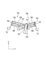
図5は、変位測定ユニット40の斜視図である。図6は、傾斜移動エアシリンダ55および変位測定器51の配置を説明する図である。
FIG. 5 is a perspective view of the
変位測定ユニット40は、変位測定器51と、変位測定器51をタイヤTのたわみ測定位置まで移動させる測定器移動機構とを備える。測定器移動機構は、水平移動エアシリンダ41と、水平移動エアシリンダ41のロッド43の先端にタイヤTへの負荷方向(Z方向)に対して傾斜させて配設された傾斜移動エアシリンダ55とを有する。そして、傾斜移動エアシリンダ55のロッド56の先端には、支持部材52を介して変位測定器51が配設されている。
The
水平移動エアシリンダ41は、変位測定器51をテーブル3から離隔した待機位置からテーブル3上の位置に移動させるためのものであり、そのロッド43は、シリンダ部42への圧縮空気の供給によりX方向に伸縮する。水平移動エアシリンダ41のシリンダ部42は、カバー部材44内に上下2段に格納され、このカバー部材44の位置調整により所定の高さ位置に配設される。この変位測定ユニット40は、一対の測定器移動機構、すなわち、上段側の水平移動エアシリンダ41に接続される傾斜移動エアシリンダ55と、下段側の水平移動エアシリンダ41に接続される傾斜移動エアシリンダ55とを備える。
The horizontally moving
傾斜移動エアシリンダ55は、水平移動エアシリンダ41のロッド43の先端にシリンダ支持部材53を介して接続される。シリンダ支持部材53には、傾斜移動エアシリンダ55のロッド56を案内する一対のガイド部材58が貫通する孔部が設けられ、ガイド部材58はロッド56の伸縮とともに移動する。
The inclined moving
また、この変位測定ユニット40は、各傾斜移動エアシリンダ55に変位測定器51を配設することで、変位測定器51を一対備える。なお、図5においては、下段側の水平移動エアシリンダ41のロッド43を伸張させた状態を示している。また、図6においては、下段側の水平移動エアシリンダ41に接続されている傾斜移動エアシリンダ55のロッド56を伸張させた状態を示している。
In addition, the
変位測定器51は光学式変位測定器であり、内部に投光部と受光部とを有し、反射式でタイヤTの表面との間の距離を測定する。この測定データから、タイヤTに径方向の圧縮荷重を負荷したときのタイヤTの変形量などが演算される。変位測定器51は、傾斜移動エアシリンダ55のロッド56の先端に接続された支持部材52に対して投光部と受光部がタイヤTの側面を向くように配設される。
The
変位測定器51は、傾斜移動エアシリンダ55のロッド56の伸縮により、タイヤTの幅方向(Y方向)とタイヤTへの負荷方向(Z方向)に対する配置が同時に変更される。傾斜移動エアシリンダ55のロッド56の伸縮は、ケーブルキャリア45に格納されたチューブを介して圧縮空気供給部34からシリンダ部57に供給される圧縮空気により実現される。なお、ケーブルキャリア45には、変位測定器51と制御部30とを接続する通信ケーブルも格納されている。
The
この発明の一軸移動機構として、この実施形態のようにエアシリンダを採用した場合には、エアシリンダのストロークに応じて、タイヤTの幅方向(Y方向)とタイヤTへの負荷方向(Z方向)に対する位置が互いに異なる2つの位置、すなわち、ロッド56が伸張しているときの位置(テーブル3の表面に垂直な負荷軸AXにより遠く、かつ、テーブル3の表面からの高さがより高い位置)と収縮しているときの位置(負荷軸AXにより近く、かつ、テーブル3の表面からの高さがより低い位置)との間で変位測定器51の位置が変更される。
When an air cylinder is employed as the uniaxial movement mechanism of the present invention as in this embodiment, the width direction (Y direction) of the tire T and the load direction (Z direction) according to the stroke of the air cylinder. ), The positions when the
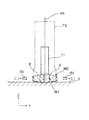
このような構成の変位測定ユニット40により、タイヤTのたわみを測定するときの動作を説明する。図7は、タイヤ圧縮試験機におけるたわみの測定の様子を説明する模式図である。なお、図中に変位測定器51の測定範囲Eを図示している。
An operation when measuring the deflection of the tire T by the
このタイヤ圧縮試験機では、傾斜移動エアシリンダ55のロッド56を収縮状態としたとき、および、伸張状態としたときの変位測定器51の測定可能範囲と、複数種類のタイヤTの幅および径などの情報とを関連付けて予め記憶部31に記憶させている。そして、オペレータが入力部33を介して試験対象となるタイヤTを選択することにより、制御部30においてタイヤTに応じた変位測定器51の位置を決定している。すなわち、傾斜移動エアシリンダ55のロッド56を収縮状態と伸張状態のいずれの状態にするかが決定される。しかる後、圧縮空気供給部34の作用により、傾斜移動エアシリンダ55のロッド56が収縮状態と伸張状態のいずれかの状態にされるとともに、水平移動エアシリンダ41が伸張し、変位測定器51がタイヤTの幅に応じた測定位置に配置される。
In this tire compression tester, when the
このタイヤ圧縮試験機の変位測定ユニット40では、傾斜移動エアシリンダ55と変位測定器51が一対配設されており、一対の傾斜移動エアシリンダ55のロッド56を同期して伸縮させることにより、一対の変位測定器51が、タイヤTの幅方向(Y方向)に対して互いに対向し、かつ、負荷軸AXに対して対称な位置関係を維持しながら近接または離隔する。一対の傾斜移動エアシリンダ55のロッド56が収縮している状態では、一対の変位測定器51は互いに近接し、かつ、テーブル3の表面により近い低い位置に配置される。一対の傾斜移動エアシリンダ55のロッド56が伸張している状態では、一対の変位測定器51は互いに離隔し、かつ、一対の傾斜移動エアシリンダ55のロッド56が収縮しているときよりもテーブル3の表面からより遠い高い位置に配置される。
In the
図7に示すように、実線で示す大型タイヤT2に合わせて、変位測定器51が実線で示す位置に配置された状態では、傾斜移動エアシリンダ55のロッド56は伸張状態となっており、大型タイヤT2が負荷を受けたときの最大たわみの出現位置が、変位測定器51の測定範囲E内となる。一方、仮想線で示す小型タイヤT1のたわみを測定するときには、傾斜移動エアシリンダ55のロッド56は収縮状態となっており、変位測定器51は仮想線で示す位置に配置される。この場合には、小型タイヤT1が負荷を受けたときの最大たわみの出現位置が、破線で示す変位測定器51の測定範囲内となる。
As shown in FIG. 7, the
なお、変位測定器51を移動させる一軸移動機構として、傾斜移動エアシリンダ55に換えて、可動ステージをモータの駆動を利用してレールやボールネジなどの軸部材に沿って移動させるものを採用することもできる。この場合は、水平移動エアシリンダ41のロッド43の先端に軸部材を傾斜させて配設するとともに、可動ステージに支持部材等を介して変位測定器51を配設する。そして、可動ステージの位置は、可動ステージを移動させる電動モータの駆動/停止を実行することにより制御できることから、軸部材上の任意の位置に可動ステージを配置することが可能となる。すなわち、変位測定器51をタイヤTの幅方向(Y方向)とタイヤTへの負荷方向(Z方向)に対する位置が互いに異なる任意の位置に移動させることが可能となる。このように、変位測定器51を任意の位置に移動させることができると、どのサイズのタイヤTであっても最大たわみの出現位置を中心とした一定の範囲でのたわみ測定が可能となる。
As a uniaxial moving mechanism for moving the
また、上述した実施形態では、一対の測定器移動機構を動作させて一対の変位測定器51の位置を変更する場合を説明したが、一方の変位測定器51のみでたわみ測定をする場合には、変位測定ユニット40の下段側の水平移動エアシリンダ41およびこれに接続されている傾斜移動エアシリンダ55(図5および図6参照)を動作させればよい。特に大型のタイヤTであって、支柱2とタイヤTとの間に変位測定器51を配置することが困難な場合には、このように一方の測定器移動機構のみ動作させ、たわみ測定を実行する。
Further, in the above-described embodiment, the case where the position of the pair of
1 台座
2 支柱
3 テーブル
4 試験治具本体
5 試験治具
6 レール
7 可動テーブル
30 制御部
31 記憶部
32 表示部
33 入力部
34 圧縮空気供給部
40 変位測定ユニット
41 水平移動エアシリンダ
42 シリンダ部
43 ロッド
44 カバー部材
45 ケーブルキャリア
51 変位測定器
52 支持部材
53 シリンダ支持部材
55 傾斜移動エアシリンダ
56 ロッド
57 シリンダ部
58 ガイド部材
T タイヤ
E 測定範囲
AX 負荷軸
DESCRIPTION OF SYMBOLS 1
Claims (5)
タイヤの幅方向の変位を検出する光学式変位測定器と、
前記光学式変位測定器を負荷方向に対して傾斜させて移動させる一軸移動機構を有し、前記光学式変位測定器のタイヤの幅方向およびタイヤへの負荷方向に対する位置を、タイヤのサイズに応じて同時に変更する測定器移動機構と、
を備えることを特徴とするタイヤ圧縮試験機。 In a tire compression tester that includes a test jig having a table as a pseudo road surface, and measures the deflection of the tire when a radial load is applied to the tire by pressing the tire as a test body against the table,
An optical displacement measuring device that detects displacement in the width direction of the tire;
The optical displacement measuring device has a uniaxial moving mechanism that moves the optical displacement measuring device while being inclined with respect to the load direction, and the position of the optical displacement measuring device with respect to the width direction of the tire and the load direction on the tire depends on the tire size. A measuring instrument moving mechanism that changes simultaneously
A tire compression tester characterized by comprising:
前記一軸移動機構は、負荷方向に対して傾斜させて配置したエアシリンダを含み、
前記測定器移動機構は、前記エアシリンダを伸縮させることにより、タイヤの幅方向およびタイヤへの負荷方向に対する位置が互いに異なる少なくとも2つの位置のうちのいずれかの位置に前記光学式変位測定器を配置するタイヤ圧縮試験機。 In the tire compression testing machine according to claim 1,
The uniaxial movement mechanism includes an air cylinder arranged to be inclined with respect to the load direction,
Said measuring device moving mechanism, by expanding and contracting the previous SL air cylinder, the optical displacement measuring instrument in any position of the width direction and position from each other at least two different positions relative to the loading direction of the tires To arrange tire compression testing machine.
前記一軸移動機構は、負荷方向に対して傾斜させて配置した軸部材を含み、
前記測定器移動機構は、前記光学式変位測定器を配設した可動ステージを前記軸部材に沿ってモータの駆動を利用して移動させることにより、タイヤの幅方向およびタイヤへの負荷方向に対する位置が互いに異なる任意の位置に前記光学式変位測定器を配置するタイヤ圧縮試験機。 In the tire compression testing machine according to claim 1,
The uniaxial movement mechanism includes a shaft member arranged to be inclined with respect to the load direction,
It said measuring device moving mechanism, the load direction of the movable stage which is disposed the optical displacement measuring instrument by a Turkey moved by using the driving of the motor along the shaft member, the width direction and the tire of the tire A tire compression testing machine in which the optical displacement measuring device is arranged at an arbitrary position different from each other.
前記光学式変位測定器は、投光部と受光部を備え、反射方式によりタイヤの幅方向の変位を検出するタイヤ圧縮試験機。 In the tire compression testing machine according to any one of claims 1 to 3,
The optical displacement measuring device includes a light projecting unit and a light receiving unit, and detects a displacement in the width direction of the tire by a reflection method.
前記光学式変位測定器および前記測定器移動機構は、一対配設され、
各測定器移動機構は、各光学式変位測定器をタイヤの幅方向に対して互いに対向させた状態で、各光学式変位測定器のタイヤの幅方向およびタイヤへの負荷方向に対する位置を同時に変更するタイヤ圧縮試験機。 In the tire compression testing machine according to any one of claims 1 to 4,
A pair of the optical displacement measuring instrument and the measuring instrument moving mechanism are arranged,
Each measuring instrument moving mechanism simultaneously changes the position of each optical displacement measuring instrument with respect to the tire width direction and the tire load direction with each optical displacement measuring instrument facing each other with respect to the tire width direction. Tire compression testing machine.
Priority Applications (1)
| Application Number | Priority Date | Filing Date | Title |
|---|---|---|---|
| JP2014244777A JP6281478B2 (en) | 2014-12-03 | 2014-12-03 | Tire compression testing machine |
Applications Claiming Priority (1)
| Application Number | Priority Date | Filing Date | Title |
|---|---|---|---|
| JP2014244777A JP6281478B2 (en) | 2014-12-03 | 2014-12-03 | Tire compression testing machine |
Publications (2)
| Publication Number | Publication Date |
|---|---|
| JP2016109475A JP2016109475A (en) | 2016-06-20 |
| JP6281478B2 true JP6281478B2 (en) | 2018-02-21 |
Family
ID=56123796
Family Applications (1)
| Application Number | Title | Priority Date | Filing Date |
|---|---|---|---|
| JP2014244777A Active JP6281478B2 (en) | 2014-12-03 | 2014-12-03 | Tire compression testing machine |
Country Status (1)
| Country | Link |
|---|---|
| JP (1) | JP6281478B2 (en) |
Families Citing this family (1)
| Publication number | Priority date | Publication date | Assignee | Title |
|---|---|---|---|---|
| CN107328587A (en) * | 2017-06-29 | 2017-11-07 | 方盛车桥(苏州)有限公司 | A kind of suspension system fatigue tester |
Family Cites Families (4)
| Publication number | Priority date | Publication date | Assignee | Title |
|---|---|---|---|---|
| JPS58148613U (en) * | 1982-03-30 | 1983-10-05 | 株式会社島津製作所 | Tire width displacement measuring device |
| JPS62232507A (en) * | 1986-04-01 | 1987-10-13 | Kobe Steel Ltd | Shape measuring device |
| US4896531A (en) * | 1988-10-11 | 1990-01-30 | Eagle-Picher Industries, Inc. | Sidewall appearance monitor |
| JP5946424B2 (en) * | 2013-05-01 | 2016-07-06 | 株式会社神戸製鋼所 | Tire testing machine |
-
2014
- 2014-12-03 JP JP2014244777A patent/JP6281478B2/en active Active
Also Published As
| Publication number | Publication date |
|---|---|
| JP2016109475A (en) | 2016-06-20 |
Similar Documents
| Publication | Publication Date | Title |
|---|---|---|
| CN100586745C (en) | Automatic detector device for a tire assembling-disassembling machine | |
| CN103292974B (en) | Chair hutch table bed screen wind dead load, stability, shock machine | |
| KR102229364B1 (en) | Test apparatus of display apparatus and testing method using the same | |
| KR102016588B1 (en) | Automatical jig for assembling ship | |
| JP5011361B2 (en) | Tire testing machine | |
| ES2942322T3 (en) | Apparatus and method for checking the inclination of a cushioning pad | |
| JP2013217829A (en) | Bending test device and bending test method using the same | |
| CN106289745B (en) | Composite material plate spring high/low temperature fatigue and rolling capability testboard bay | |
| KR20130097668A (en) | Probe apparatus and parallelism adjustment mechanism of a probe card | |
| KR101957883B1 (en) | Rectangular panel bending device | |
| CN204115679U (en) | Many laser planeness surveying instrument | |
| JP6281478B2 (en) | Tire compression testing machine | |
| JP5796104B1 (en) | Contact module for measuring electronic components | |
| CN104344968A (en) | Tire testing machine | |
| KR100887504B1 (en) | Apparatus for inserting sealing material cylindrical component | |
| KR101869005B1 (en) | Automatical jig for assembling ship | |
| CN106168458A (en) | A kind of device detecting T-shaped hole axiality | |
| CN202622068U (en) | Stress end jumping detection corrector of round cutting saw | |
| CN102706300B (en) | Height detecting device | |
| CN109443269A (en) | Bearing outer ring automatic detection device | |
| KR101115543B1 (en) | Structure test appuratus of damping prop | |
| KR101820023B1 (en) | Apparatus for Testing LM Guide | |
| JP2014240814A (en) | Device for measuring flatness of cylindrical member edge face | |
| CN103698630B (en) | A kind of electrical array detection equipment | |
| US9151643B2 (en) | Measuring apparatus and controlling method thereof |
Legal Events
| Date | Code | Title | Description |
|---|---|---|---|
| A621 | Written request for application examination |
Free format text: JAPANESE INTERMEDIATE CODE: A621 Effective date: 20170228 |
|
| A977 | Report on retrieval |
Free format text: JAPANESE INTERMEDIATE CODE: A971007 Effective date: 20171110 |
|
| A131 | Notification of reasons for refusal |
Free format text: JAPANESE INTERMEDIATE CODE: A131 Effective date: 20171121 |
|
| A521 | Request for written amendment filed |
Free format text: JAPANESE INTERMEDIATE CODE: A523 Effective date: 20171214 |
|
| TRDD | Decision of grant or rejection written | ||
| A01 | Written decision to grant a patent or to grant a registration (utility model) |
Free format text: JAPANESE INTERMEDIATE CODE: A01 Effective date: 20171226 |
|
| A61 | First payment of annual fees (during grant procedure) |
Free format text: JAPANESE INTERMEDIATE CODE: A61 Effective date: 20180108 |
|
| R151 | Written notification of patent or utility model registration |
Ref document number: 6281478 Country of ref document: JP Free format text: JAPANESE INTERMEDIATE CODE: R151 |