JP6278905B2 - Holder frame for sensor means in the vehicle - Google Patents
Holder frame for sensor means in the vehicle Download PDFInfo
- Publication number
- JP6278905B2 JP6278905B2 JP2014559098A JP2014559098A JP6278905B2 JP 6278905 B2 JP6278905 B2 JP 6278905B2 JP 2014559098 A JP2014559098 A JP 2014559098A JP 2014559098 A JP2014559098 A JP 2014559098A JP 6278905 B2 JP6278905 B2 JP 6278905B2
- Authority
- JP
- Japan
- Prior art keywords
- holder frame
- sensor means
- guide track
- guide
- sensor
- Prior art date
- Legal status (The legal status is an assumption and is not a legal conclusion. Google has not performed a legal analysis and makes no representation as to the accuracy of the status listed.)
- Expired - Fee Related
Links
Images


Classifications
-
- B—PERFORMING OPERATIONS; TRANSPORTING
- B60—VEHICLES IN GENERAL
- B60R—VEHICLES, VEHICLE FITTINGS, OR VEHICLE PARTS, NOT OTHERWISE PROVIDED FOR
- B60R11/00—Arrangements for holding or mounting articles, not otherwise provided for
- B60R11/02—Arrangements for holding or mounting articles, not otherwise provided for for radio sets, television sets, telephones, or the like; Arrangement of controls thereof
-
- B—PERFORMING OPERATIONS; TRANSPORTING
- B60—VEHICLES IN GENERAL
- B60R—VEHICLES, VEHICLE FITTINGS, OR VEHICLE PARTS, NOT OTHERWISE PROVIDED FOR
- B60R11/00—Arrangements for holding or mounting articles, not otherwise provided for
- B60R11/04—Mounting of cameras operative during drive; Arrangement of controls thereof relative to the vehicle
-
- B—PERFORMING OPERATIONS; TRANSPORTING
- B60—VEHICLES IN GENERAL
- B60R—VEHICLES, VEHICLE FITTINGS, OR VEHICLE PARTS, NOT OTHERWISE PROVIDED FOR
- B60R11/00—Arrangements for holding or mounting articles, not otherwise provided for
- B60R2011/0001—Arrangements for holding or mounting articles, not otherwise provided for characterised by position
- B60R2011/0003—Arrangements for holding or mounting articles, not otherwise provided for characterised by position inside the vehicle
- B60R2011/0026—Windows, e.g. windscreen
-
- B—PERFORMING OPERATIONS; TRANSPORTING
- B60—VEHICLES IN GENERAL
- B60R—VEHICLES, VEHICLE FITTINGS, OR VEHICLE PARTS, NOT OTHERWISE PROVIDED FOR
- B60R11/00—Arrangements for holding or mounting articles, not otherwise provided for
- B60R2011/0042—Arrangements for holding or mounting articles, not otherwise provided for characterised by mounting means
- B60R2011/0049—Arrangements for holding or mounting articles, not otherwise provided for characterised by mounting means for non integrated articles
- B60R2011/005—Connection with the vehicle part
Landscapes
- Engineering & Computer Science (AREA)
- Mechanical Engineering (AREA)
- Fittings On The Vehicle Exterior For Carrying Loads, And Devices For Holding Or Mounting Articles (AREA)
- Window Of Vehicle (AREA)
- Optical Radar Systems And Details Thereof (AREA)
Description
本発明は、車両の内部、車両ガラスに配置するためのホルダー枠、並びに、ホルダー枠内への少なくとも一つのセンサー手段の配置に関する。更に本発明は、車両の内部、車両ガラスの後ろに配置され、本発明に係るホルダー枠を包含するセンサー配置にも関する。 The present invention relates to an interior of a vehicle, a holder frame for placement on a vehicle glass, and an arrangement of at least one sensor means in the holder frame. The invention further relates to a sensor arrangement which is arranged inside the vehicle, behind the vehicle glass and which includes a holder frame according to the invention.
現代的な車両では、例えば、ドライバー・アシスタント・システム用に、より多くのセンサー手段が、採用されるようになった。このようなセンサー手段は、多くの場合、固定手段によって車両のフロントガラスの後ろに配置され、その視野は、フロントガラスを介して走行方向に向けられている。センサー手段の例としては、レーダー・センサー、超音波センサー、レーザー・センサー、乃至、ライダー・センサー、並びに、例えば、オブジェクト、障害物、車線境界までの間隔測定、及び/或いは、これらの認識用など様々な仕様の車両用カメラが挙げられる。 In modern vehicles, more sensor means have been adopted, for example, for driver assistance systems. Such sensor means are often arranged behind the windshield of the vehicle by fixing means, the field of view of which is directed in the direction of travel through the windshield. Examples of sensor means include radar sensors, ultrasonic sensors, laser sensors or lidar sensors, and for example distance measurement to objects, obstacles, lane boundaries, and / or their recognition. There are various types of vehicle cameras.
車両カメラのフロントガラスの後ろへの配置用の固定手段は、例えば、DE 10 2010 010 571 A1より既知である。 Fixing means for placement behind the windshield of a vehicle camera is known, for example, from DE 10 2010 010 571 A1.
しかしながらこれまでにセンサー手段用に用いられてきた固定手段には、様々な欠点がある。 However, the fixing means used so far for the sensor means have various drawbacks.
既知の固定手段内のセンサー手段の取付ならびに取外しは、頻繁に困難であり、通常、強い力が必要、特に、取付公差、乃至、位置公差が、金属製のバネやプラスチック製のバネなど弾性部品によって調整される場合には、強い力が必要である。このような弾性部品は、多くの場合、特に、該弾性部品が、センサー手段を、車両ガラスから離すように押している場合、それの機能とは逆方向、即ち、センサー手段の固定方向、或いは、取付方向とは、逆方向に作用している。 Mounting and removal of the sensor means in the known fastening means are often difficult, typically, requires a strong force, in particular, mounting tolerances, to the position tolerance, such as a metal spring or plastic-made spring bullets A strong force is required when adjusted by a sexual component. Such elastic components are often particularly, the bullet resistant component, if the sensor means, is pressed and away from the vehicle glass, reverse to that of the function, i.e., a fixed direction of the sensor means, Or, it acts in the opposite direction to the mounting direction.
特に、カチッとはめ込む、或いは、噛み合うことと弾性による固定を組み合わせた固定手段では、例えば、プラスチック・バネなど弾性のあるプラスチック部品において、例えば、弾性プラスチック部品が、温度や経時によりクリープ、及び/或いは、曲がりと言った好ましくない現象が起こる。これにより、車内において、その寿命の間に固定手段内でセンサー手段が緩むことになる。 In particular, it fitted into place, or in that the fixing means combining fixed by elastic meshing, for example, creep in the plastic parts with like elastic plastic spring, for example, elastic plastic component, the temperature or time, And / or an undesirable phenomenon such as bending occurs. Thereby, in the vehicle, the sensor means is loosened in the fixing means during its lifetime.
よって本発明の課題は、可能な限り単純で、低コスト、そして、長時間安定したセンサー手段の車両ガラス裏側における固定手段を提供できるソリューションを開示することである。 It is therefore an object of the present invention to disclose a solution that can provide a means for fixing the sensor means on the backside of the vehicle glass that is as simple as possible, inexpensive and stable for a long time.
この課題は、ある手段、具体的には、請求項1の特徴を持つホルダー枠、並びに、請求項8の特徴を持つセンサー配置によって解決される。本発明の更なる実施形態、並びに、発展形態は、従属請求項から得られるが、各特徴を組み合わせること、更には各特徴の更なる発展形態も考え得る。
This problem is solved by a means, in particular a holder frame with the features of
本発明の基本的なアイデアは、車両ガラスの後ろにセンサー手段を配置する役割を担う固定手段を、ホルダー枠の形状に構成すると言うことである。その際、該ホルダー枠は、枠の片側、或いは、末端に形成されているガイドトラックを包含している。尚、該ガイドトラックは、好ましくは、該ガイドトラック内でのガイドに合うように構成された支持エレメントを包含するセンサー手段が、ガイドトラックのそれぞれの構成によって定まるトラックに沿って、車両ガラス側へと導かれることができるように構成されている。好ましくは、枠の向かい側、或いは、向かいにある末端、及び/或いは、センサー手段の対応する側に構成された、適した手段を介して、ガイドトラックのガイド方向へ、これにより、センサー手段、乃至、センサー手段の支持エレメントが、ホルダー枠内に配置された際に、ガイドトラック内を強制的にガイドされるのに適した機械的な力を発生させることができる。尚、ホルダー枠内でのセンサー手段の固定は、好ましくは、付加的な、弾性を有する、或いは、バネ力のある手段によって実施される。この発明の重要な特長は、ホルダー枠内でのセンサー手段の固定のためには、僅かな力しか必要とされず、よって、弾性を有する、或いは、バネ力のあるコンポーネントによる固定は、基本的に、力をかけることなく実施可能なことである。僅かな力によって実施することにより、温度や経時によってクリープ、曲がり、及び/或いは、ゆるみと言った欠点を回避することができる。 The basic idea of the present invention is that the fixing means responsible for placing the sensor means behind the vehicle glass is configured in the shape of a holder frame. In this case, the holder frame includes a guide track formed on one side or the end of the frame. The guide track preferably has a sensor means including a support element configured to fit the guide in the guide track along the track determined by the respective configuration of the guide track toward the vehicle glass side. It is comprised so that it can be guided. Preferably, in the guide direction of the guide track via suitable means arranged on the opposite side of the frame or on the opposite end and / or on the corresponding side of the sensor means, thereby the sensor means, When the support element of the sensor means is arranged in the holder frame, it is possible to generate a mechanical force suitable for being forcibly guided in the guide track. The fixing of the sensor means in the holder frame, preferably, additional, having elastic, or is carried out by means of a spring force. An important feature of this invention, for fixation of the sensor means in the holder frame is not required only a small force, thus having elastic or fixed by the component with a spring force, the basic In particular, it can be implemented without any effort. By performing by a slight force, creep with temperature or time, bending, and / or, it is possible to avoid loosening and said disadvantages.
本発明に係るホルダー枠は、車両の内部空間に、特に好ましくは、車両ガラスに配置することができ、特に好ましくは、該センサー手段の視線方向が、ホルダー枠と車両ガラスを通過するように、少なくとも一つのセンサー手段の配置、或いは、固定を実施する役割を担っている。該ホルダー枠は、更なるコンポーネントから構成される固定手段、特に好ましくは、例えば、バックミラーやインジケータパネルなど車両側の装置の一部であることも可能である。よって、該ホルダー枠は、複数の電子コンポーネント、特に、様々なセンサー手段類用の大きな固定手段の一部であることも可能である。このような固定手段は、ブラケットと呼ばれることもある。本発明に係るホルダー枠の基本的形状自体は、任意である。但し、多角形、特に、正方形や長方形など、少なくとも四本の直線的に延びるフレーム辺を包含する基本的形状を有する実施形態が特に目的にかなっている。該ホルダー枠は、例えば、接着接続を介して車両ガラスに直接配置されることができる。特に、枠(フレーム)と言う形状の実施形態であることから、センサー手段は、ホルダー枠、並びに、車両ガラスを貫通する視線方向をもって、該ホルダー枠内に配置されることが可能である。ここで言う「車両ガラス」とは、特に好ましくは、車両のフロントガラス、或いは、リアガラスであり、よって、ホルダー枠内に配置されるセンサー手段は、例えば、車両の前方に、或いは、後方に横たわる周辺領域、特に、交通空間を捕捉する役割を担うものである。これらの本発明に係るホルダー枠内に配置されることができるセンサー手段とは、好ましくは、車載カメラである。しかし、複数の、及び/或いは、他のセンサー手段、例えば、超音波センサー、レーダー・センサー、或いは、ライダー・センサー、及び/或いは、車両ガラスの表面に設置される雨を検知する雨センサーなども、ホルダー枠内に配置されることができる。 The holder frame according to the present invention can be arranged in the interior space of the vehicle, particularly preferably in the vehicle glass, and particularly preferably so that the line-of-sight direction of the sensor means passes through the holder frame and the vehicle glass. It plays a role of arranging or fixing at least one sensor means. The holder frame can also be part of a vehicle-side device, such as a fixing means composed of further components, particularly preferably a rearview mirror or an indicator panel, for example. Thus, the holder frame can also be part of a large fixing means for a plurality of electronic components, in particular various sensor means. Such a fixing means is sometimes called a bracket. The basic shape of the holder frame according to the present invention is arbitrary. However, embodiments having a basic shape including at least four linearly extending frame sides, such as polygons, in particular squares and rectangles, are particularly suitable. The holder frame can for example be placed directly on the vehicle glass via an adhesive connection. In particular, since it is an embodiment of a shape called a frame, the sensor means can be arranged in the holder frame with a sight line direction penetrating the holder frame and the vehicle glass. The “vehicle glass” as used herein is particularly preferably a windshield or rear glass of the vehicle, so that the sensor means arranged in the holder frame lies, for example, in front of or behind the vehicle. It plays the role of capturing surrounding areas, especially traffic spaces. The sensor means that can be arranged in the holder frame according to the present invention is preferably an in-vehicle camera. However, a plurality of and / or other sensor means such as an ultrasonic sensor, a radar sensor, or a rider sensor, and / or a rain sensor for detecting rain installed on the surface of a vehicle glass, etc. Can be placed in the holder frame.
該ホルダー枠は、本発明では、少なくとも片側、或いは、少なくとも一つの末端に、好ましくは、前方の末端にガイドトラックが設けられている。ここで、該ガイドトラックは、ホルダー枠内に配置することが可能なセンサー手段の、好ましくは、対応する片側、或いは、対応する末端に形成されている支持エレメントを取付けるための役割を担っている。該ガイドトラックは、センサー手段をホルダー枠内に配置する際、センサー手段の支持エレメントが、該ガイドトラック内へ、センサー手段が、車両ガラス側へ接近するようにガイドすることができるように形成されていることが好ましい。 In the present invention, the holder frame is provided with a guide track on at least one side or at least one end, preferably on the front end. Here, the guide track serves to attach a support element formed on the corresponding one side or the corresponding end of the sensor means which can be arranged in the holder frame. . The guide track is formed such that when the sensor means is placed in the holder frame, the support element of the sensor means can be guided into the guide track so that the sensor means approaches the vehicle glass side. It is preferable.
本発明に係るホルダー枠は、少なくとも一つのガイドトラックの向かい側、或いは、ガイドトラックの向かい側の末端の領域に、センサー手段をホルダー枠に配置した際に、基本的に、ガイドトラックのガイド方向へ作用する、特に、テンション力、或いは、スプリング力と言った機械的な力を発生させるための手段を包含しており、これにより、センサー手段をホルダー枠に配置した際に、これらの手段が、センサー手段の支持エレメントをガイドトラックへとガイドする、乃至、強制的に導くことができるようになっている。該手段は、好ましくは、ホルダー枠の後ろの末端に形成されていることが好ましい。 The holder frame according to the present invention basically acts in the guide direction of the guide track when the sensor means is arranged on the holder frame at the opposite side of at least one guide track or at the end region on the opposite side of the guide track. In particular, it includes means for generating a mechanical force, such as tension force or spring force, so that when the sensor means is placed on the holder frame, these means are The support element of the means can be guided or forcibly guided to the guide track. The means is preferably formed at the rear end of the holder frame.
ここで言う「基本的にガイド方向」と言う方向は、特に、該手段によって発生された力の作用方向のことであるが、該作用方向とは、ガイドトラックのガイド方向、或いは、ガイドトラックのガイド方向の平均から90°未満異なる、好ましくは、該手段によって発生された力が、センサー手段の支持エレメントのガイドトラックへガイドするために作用する方向のことである。ここで言う「ガイド方向」とは特に、センサー手段の支持エレメントガイドトラックへと導く、或いは、センサー手段をホルダー枠内に配置する際に、車両ガラス側へと導く方向のことを意味している。 The direction referred to herein as “basic guide direction” refers in particular to the direction of action of the force generated by the means. The direction of action refers to the guide direction of the guide track or the guide track. It is the direction in which the force generated by the means acts to guide to the guide track of the support element of the sensor means, preferably less than 90 ° from the average of the guide direction. The “guide direction” here means in particular the direction leading to the support element guide track of the sensor means, or to the vehicle glass side when the sensor means is arranged in the holder frame. .
本発明に係るホルダー枠のある好ましい実施形態においては、機械的力を発生するための手段は、リジッド、及び/或いは、フレキシブル(乃至、弾性のある)なガイドスロープとして構成されている。該ガイドスロープは、この際、ホルダー枠内への配置の際にセンサー手段を、該センサー手段をガイドトラックのガイド方向である方向に動くことを強制し、センサー手段の支持エレメントがガイドトラック内でガイドされるように導くように構成された斜めの面であることが好ましい。 In certain preferred embodiments of the holder frame according to the present invention, means for generating a mechanical force, rigid, and / or flexible (or, bullet resistant there) is constructed as a guide slope. The guide slope then forces the sensor means to move the sensor means in a direction that is the guide direction of the guide track when placed in the holder frame, so that the support element of the sensor means moves within the guide track. It is preferable that the surface is an oblique surface configured to be guided.
本発明に係るホルダー枠の有利な実施形態では、該ホルダー枠に、センサー手段をホルダー枠内に機械的に固定する手段が、付加的に設けられている。該「付加的な手段」とは、例えば、センサー手段を、特に、これが最終ポジションに達した時に、例えば、カチッと嵌る、或いは、噛み合うことで、ホルダー枠に固定するための、スプリング・エレメントであることができる。付加的な手段による固定はこの際、好ましくは、センサー手段を、ホルダー枠からの落下を防止する、特に、ガイドトラックのガイド方向に対して鉛直方向におけるセンサー手段の位置を確実にする役割を担っている。特に、ガイド方向に対して鉛直方向への確実性が得られるため、これは、本質的に、力をかけることなく、乃至、僅かな力で実施できる。 In an advantageous embodiment of the holder frame according to the invention, the holder frame is additionally provided with means for mechanically fixing the sensor means in the holder frame. The “additional means” is, for example, a spring element for fixing the sensor means to the holder frame, for example, when it reaches the final position, eg by snapping or engaging. Can be. In this case, the fixing by the additional means preferably serves to prevent the sensor means from falling off the holder frame, in particular to ensure the position of the sensor means in the direction perpendicular to the guide direction of the guide track. ing. In particular, since a certainty in the vertical direction with respect to the guide direction is obtained, this can be carried out essentially without any force or with a slight force.
本発明に係るホルダー枠の特別な実施形態では、ガイドトラックは、基本的にS字状のプロファイルに構成されている。このような実施形態の主な利点は、センサー手段が、本発明に係るホルダー枠に配置された時、支持エレメントを介して、定義されたS字状のアーチ内を、車両ガラス側へと導かれると言うことにある。 In a special embodiment of the holder frame according to the invention, the guide track is basically configured in an S-shaped profile. The main advantage of such an embodiment is that when the sensor means is arranged in the holder frame according to the invention, the defined S-shaped arch is guided to the vehicle glass side via the support element. It is to be said to be taken.
本発明に係るホルダー枠のある好ましい実施形態においては、該ガイドトラックは、支持エレメントのエンド・ポジションの領域において、ホルダー枠内のセンサー手段のエンド・ポジションにおいて、基本的に、車両ガラスと平行にセットされる。 In a preferred embodiment of the holder frame according to the invention, the guide track is essentially parallel to the vehicle glass at the end position of the sensor means in the holder frame in the region of the end position of the support element. Set.
本発明に係るセンサー配置は、車両の内部空間の車両ガラスの後ろ、特に好ましくは、フロントガラスの後ろに配置され、上記の実施形態のうちの一つに従って構成されているホルダー枠を包含している。本発明に係るセンサー配置は、更に、ホルダー枠内に配置される少なくとも一つのセンサー手段も包含している。該センサー手段は、特にホルダー枠の、該ガイドトラックが設けられている片側、或いは、末端に対応している片側に、ホルダー枠にセンサー手段を配置する場合、センサー手段をホルダー枠のガイドトラック内にガイドするための、並びに、ホルダー枠内において、望まれるエンド・ポジションに達した際に、センサー手段を固定する役割を果たす支持エレメントを備えるように構成されている。 The sensor arrangement according to the invention includes a holder frame arranged behind the vehicle glass in the interior space of the vehicle, particularly preferably behind the windshield and configured according to one of the above embodiments. Yes. The sensor arrangement according to the invention further includes at least one sensor means arranged in the holder frame. When the sensor means is arranged on the holder frame, particularly on one side of the holder frame where the guide track is provided or one side corresponding to the end, the sensor means is placed in the guide frame of the holder frame. And a support element which serves to fix the sensor means when the desired end position is reached in the holder frame.
本発明に係るセンサー配置のある好ましい実施形態においては、該センサー手段は、ガイドトラックの向かい側、或いは、ホルダー枠の末端に対応する側、乃至、これに向いている側に、特に、該配置において、センサー手段を、ホルダー枠内において、主に、ガイドトラックのガイド方向に向かって、該センサー手段に作用する機械的な力を発生させるための手段を備えるように構成されている。該手段は更に、例えば、ホルダー枠内においてセンサー手段がエンド・ポジションに達した時に、カチッと嵌ることによりセンサー手段を固定できるように構成されていることもできる。 In a preferred embodiment of the sensor arrangement according to the invention, the sensor means are located on the opposite side of the guide track or on the side corresponding to the end of the holder frame or on the side facing it, in particular in this arrangement. The sensor means is configured to include means for generating a mechanical force acting on the sensor means in the holder frame mainly in the guide direction of the guide track. The means may further be configured such that, for example, when the sensor means reaches the end position in the holder frame, the sensor means can be fixed by clicking.
本発明に係るセンサー配置の特別な実施形態では、センサー手段は、特にその視線方向、或いは、捕捉方向が、ホルダー枠を貫通する車載カメラである。 In a special embodiment of the sensor arrangement according to the invention, the sensor means is an in-vehicle camera whose sight line direction or capture direction in particular penetrates the holder frame.
センサー配置の有利な実施形態では、センサー手段に形成されている支持エレメントは、シリンダー状のピンである。該シリンダー状のピンには、それぞれ、特に、センサー手段をホルダー枠のガイドトラックへガイドする際の公差補正用の、少なくとも一つのシェーブ・ノーズを備えるように構成されていることができる。該シェーブ・ノーズは、この際、支持エレメント上に、該シェーブ・ノーズが、支持エレメントのガイドトラック内への配置、乃至、ガイドの際に、例えば、センサー手段とガラスの間隔が一定となるように車両ガラスに向けられているように、形成されていることが好ましい。該支持エレメントは、シリンダー状である必要は無く、他の形状を有していてもよいが、支持エレメントは、ガイド枠のガイドトラックの大きさや構成に合う形状に構成されていることが好ましい。 In an advantageous embodiment of the sensor arrangement, the support element formed on the sensor means is a cylindrical pin. Each of the cylindrical pins can in particular be configured with at least one shave nose for correcting tolerances when guiding the sensor means to the guide track of the holder frame. At this time, the shave nose is arranged on the support element so that the distance between the sensor means and the glass becomes constant, for example, when the support element is arranged in the guide track of the support element. It is preferably formed so as to be directed to the vehicle glass. The support element does not have to be cylindrical and may have other shapes, but the support element is preferably configured in a shape that matches the size and configuration of the guide track of the guide frame.
本発明に係るホルダー枠、並びに、本発明に係るセンサー配置の更なる長所やオプション的実施形態は、以下の、明細書内の説明、及び、図によって開示される。実施例を図に簡略的に示し、以下に詳しく説明する。 Further advantages and optional embodiments of the holder frame according to the invention as well as the sensor arrangement according to the invention are disclosed by the following description and figures in the description. Examples are shown schematically in the figures and are described in detail below.
図1には、本発明に係るホルダー枠1の一例が、示されている。該ホルダー枠1は、一般的には、四辺で枠プロファイルを形成する側辺を有する長方形の形状を有しているが、各々二つの枠の辺は、互いに平行に向か合っている。ホルダー枠1の、後方側3、乃至、後ろの末端と向かい合っている前方の末端、乃至、前方側2には、二つのガイドトラック4が、形成されている。ガイドトラック4は、本発明のホルダー枠1に配置することのできるセンサー手段8に設けられた支持エレメント10を収容する役割を果たす。ホルダー枠のガイドトラック4の向かい側3には、センサー手段8に、特に、ホルダー枠1へのセンサー手段8の配置の際に、本発明では、これによりセンサー手段8に形成されることができる支持エレメント10のガイドが、ガイドトラック4内に強制的に収められる力Fを発生させるための手段も形成されている。尚、該手段とは、このケースでは、ガイドスロープ7である。
FIG. 1 shows an example of a
図2aと2bは、それぞれ、本発明に係るホルダー枠1の更なる一例を異なる視点から示している。ホルダー枠1は、ホルダー枠1の前側2に形成されているガイドトラック4を包含している。ホルダー枠1は、更に、ホルダー枠1のガイドトラック4の向かい側3、或いは、後ろ側3に形成された手段も包含している。
Figures 2a and 2b each show a further example of the
該手段とは、第一に、ホルダー枠1内にセンサー手段8をカチッと嵌ることにより固定できるように、或いは、そのポジション、特に、ガイドトラック4のガイド方向に対して鉛直方向に固定するように形成されたスプリング・エレメント5である。
スプリング・エレメント5は、部分的に、そこに、対応するエレメント17、例えば、センサー手段8に設けられていることができるフラット・スプリングが、カチッと嵌る、或いは、噛み合うことができる切り欠き部5.1を有している。該スプリング・エレメント5は、更に、センサー手段8を手動で取り外すための、或いは、これによりホルダー枠1内でのセンサー手段8のスプリング・エレメント5を介した固定を可能にするロック解除エレメント6も備えている。更なる手段としては、ホルダー枠1のガイドトラック4の向かい側3に、傾斜のあるガイドトラック7と、ホルダー枠1に配置した際にセンサー手段8に、ガイドトラック4のガイド方向にかかる力Fを発生させ、センサー手段8のガイド、乃至、ガイドトラック4の支持エレメント10に作用するリジッドなガイド・エレメント11が配置されている。リジッドなガイド・エレメント11は、特に、横方向のガイド、乃至、ホルダー枠1への配置の際にセンサー手段8の横方向のセンタリングに役割を担う。
The means is, firstly, so that the sensor means 8 can be fixed by snapping it into the
The
図3は、本発明に係るホルダー枠1の原理説明図、特に、ホルダー枠1内におけるセンサー手段8の配置の際の機能原理を描写している。図3によれば、ホルダー枠1は、例えば、車両のフロントガラスなど、車両ガラス9に設けられる。ホルダー枠1の前側2は、本発明では、ガイドトラック4として構成されている。ホルダー枠1の向かい側3のガイドトラック4には、特に、ホルダー枠内にセンサー手段8を配置する際に、センサー手段8の支持エレメント10を、ガイドトラック4内へとガイドするための力Fを強要する手段7が設けられている。即ち、センサー手段8の配置は、該手段7を介して、支持エレメント10のガイドトラック4内へのガイド対して、ガイドトラック4のガイド方向へセンサー手段8が、車両ガラス9へ近づくように導かれるように、作用する。ガイドトラック4は、図3の例では、S字状のプロファイルを有するように構成されており、センサー手段8の、乃至、その支持エレメント10のエンド・ポジションに対応する領域13では、車両ガラス9に対して平行な向きを有している。ここでは、センサー手段8に形成されている支持エレメント10は、シリンダー状のピンとして表されている。エンド・ポジション13においてガイドトラック4が平行であり、センサー手段8の支持エレメント10が、シリンダー状に形成されていることにより、非常に簡単、且つ、比較的力を必要としないセンサー手段8のホルダー枠1内での固定が達成される。ホルダー枠1のガイドトラック4の向かい側3に形成されている手段7は、ここでは、ガイドトラック4内において支持エレメント10をガイドするためには、僅かな力Fのみしか発生させる必要はない。ホルダー枠1のガイドトラック4の向かい側3にある付加的な、カチッと嵌る、或いは、噛み合う機構を備えた手段5を介して、ホルダー枠1からセンサー手段8が落ちないように固定するだけで良いことから、有利なことに比較的僅かな力で可能な、長時間安定したセンサー手段8の位置決めが達成される。これによりセンサー手段をセットする、乃至、固定する時、例えば、流れる、センサー手段が外れるなど、不利な現象は、おこらない。
FIG. 3 is a diagram illustrating the principle of the
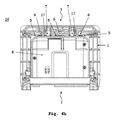
図4aからdは、本発明に係るセンサー配置14の一例をそれぞれ異なる視点から示している。該センサー配置14は、例えば、車両の内部空間の車両ガラス9の後ろに配置されることができ、ホルダー枠1とセンサー手段8を包含している。ここで言うセンサー手段8とは、車載カメラ15とLIDARセンサー16(Light Detection And Ranging)の組み合わせである。該センサー手段8は、ホルダー枠1のガイドトラック4内に配置される支持エレメント10を包含している。該ホルダー枠1は、ここでは、図2aと2bに示す本発明に係るホルダー枠1である。ホルダー枠1のガイドトラック4は、ホルダー枠1内においてセンサー手段8が、該ガイドトラック4内の支持エレメント10によって定義されたトラックを通り、車両ガラス9へ接近するように導かれることができるように構成されている。センサー配置14は、図示されている実施例では、ガイドトラック4の向かい側3に、このケースでは、センサー手段8のストッパ部17とホルダー枠1スプリング・エレメント5の切り欠き部5.1から構成され、支持エレメント10が、ガイドトラック4内のエンド・ポジションに達し、特に、センサー手段8の後ろをホルダー枠1に押し込むことによって互いにカチッと嵌る、或いは、噛み合うロック機構を備えている。
Figures 4a to 4d show an example of a
図5aから5dは、本発明に係るホルダー枠1、乃至、本発明に係るセンサー配置14の様々なエレメントを図示している。図5aと5bは、それぞれ、本発明に係るホルダー枠1の前方部分2の詳細図であり、ガイドトラック4の好ましい実施形態を示している。図5cは、本発明に係るホルダー枠1内のガイドトラック4内にあるセンサー手段8の支持エレメント10を示している。図5dは、センサー手段8の前方領域の詳細、並びに、センサー手段8に設けられている支持エレメント10を示している。このケースでは、該支持エレメント10には、シェーブ・ノーズ12が、設けられている。該シェーブ・ノーズ12は、公差補正の役割を担い、支持エレメント10の上側に、即ち、ホルダー枠1内でのセンサー手段の配置においては車両ガラス9側にあり、該支持エレメント10が、ホルダー枠1内でのセンサー手段8の配置において、該シェーブ・ノーズ12によって下方(要するに、該車両ガラス9から離れる方向)に押され、これにより、センサー手段8から車両ガラス9への間隔が一定に維持される。図5dのセンサー手段8には、その車両ガラス9側に弾性のあるエレメント18が、設けられている。例えば、スポンジ・ラバー製である該弾性のあるエレメント18は、ホルダー枠1内でのセンサー手段8の配置においては、ガラス9とセンサー手段8の間に直接設けられており、例えば、振動からくる音の発生を防止する、及び/或いは、LIDARセンサー16から照射された光と受信される光線を分ける役割を果たしている。
Figures 5a to 5d illustrate the various elements of the
1. ホルダー枠
2. ホルダー枠の前側、或いは、前の末端(ガイドトラックのある側)
3. ホルダー枠の後側、或いは、後の末端(ガイドトラックの向かい側)
4. ガイドトラック
5. フラット・スプリング
5. 1切り欠き部
6. ロック解除エレメント
7. ガイドスロープ
8. センサー手段
9. 車両ガラス
10.支持エレメント
11.横方向の心出し用のリジッドなガイド・エレメント
12.シェーブ・ノーズ
13.最終ポジションの領域
14.センサー配置
15.車載カメラ
16.LIDARセンサー
17.ロック機構のリミッター
18.弾性のあるエレメント
F フォース、主にガイドトラックのガイド方向への力
1.
3. Rear side of holder frame or rear end (opposite side of guide track)
4). 4. Guide
Claims (8)
−センサー手段(8)に設けられている支持エレメント(10)を収納するためにホルダー枠(1)の片側(2)に形成されているガイドトラック(4)、
但し、該ガイドトラック(4)は、センサー手段(8)をホルダー枠(1)内に配置する際、支持エレメント(10)が、該ガイドトラック(4)内へ、センサー手段(8)が、車両ガラス(9)側へ接近するよう導かれることができるように形成されている、
を、並びに、
−ガイドトラック(4)の向かい側(3)、或いは、ホルダー枠(1)の末端に対応する側に、センサー手段(8)を、ホルダー枠(1)内において、主に、ガイドトラック(4)のガイド方向に向かって、該センサー手段(8)に作用する機械的な力(F)を発生させるための手段(7)、
但し、該手段(7)は、センサー手段(8)のホルダー枠(1)内への配置において、支持エレメント(10)をガイドトラック(4)内へガイドする役割を担っており、
該手段(7)が弾性のガイドスロープ(7)であり、
これらのガイドスロープが斜めの面により構成されており、これらの面に、センサー手段(8)がホルダー枠(1)内に配置する際に、ガイドスロープがその弾性により撓み、センサー手段(8)がガイドトラック(4)のガイド方向へ動くことが強制され並びにセンサー手段(8)の支持エレメント(10)が、ガイドトラック(4)の内部に案内されることが強制されるように案内されることを特徴とするホルダー枠(1)。 A holder frame for the arrangement of the interior space of the vehicle behind the vehicle glass (9) and the arrangement of the at least one sensor means (8) in the holder frame (1),
A guide track (4) formed on one side (2) of the holder frame (1) for accommodating a support element (10) provided on the sensor means (8),
However, when the sensor means (8) is placed in the holder frame (1), the guide track (4) has the support element (10) inserted into the guide track (4) and the sensor means (8) It is formed so that it can be guided to approach the vehicle glass (9) side,
As well as
The sensor means (8) on the opposite side (3) of the guide track (4) or on the side corresponding to the end of the holder frame (1), the guide track (4) mainly in the holder frame (1) Means (7) for generating a mechanical force (F) acting on the sensor means (8) towards the guide direction of
However, the means (7) plays a role of guiding the support element (10) into the guide track (4) in the arrangement of the sensor means (8) in the holder frame (1).
The means (7) is an elastic guide slope (7);
These guide slopes are constituted by slanted surfaces, and when the sensor means (8) is arranged in the holder frame (1) on these faces, the guide slope is bent by its elasticity, and the sensor means (8). Is forced to move in the guide direction of the guide track (4) and the support element (10) of the sensor means (8) is guided to be guided inside the guide track (4). Holder frame (1) characterized in that.
Applications Claiming Priority (3)
| Application Number | Priority Date | Filing Date | Title |
|---|---|---|---|
| DE102012101781.6 | 2012-03-02 | ||
| DE102012101781.6A DE102012101781B4 (en) | 2012-03-02 | 2012-03-02 | Support frame for sensor devices in vehicles |
| PCT/DE2013/100045 WO2013127388A1 (en) | 2012-03-02 | 2013-02-08 | Retaining frame for sensor devices in vehicles |
Publications (3)
| Publication Number | Publication Date |
|---|---|
| JP2015508728A JP2015508728A (en) | 2015-03-23 |
| JP2015508728A5 JP2015508728A5 (en) | 2017-11-24 |
| JP6278905B2 true JP6278905B2 (en) | 2018-02-14 |
Family
ID=47779800
Family Applications (1)
| Application Number | Title | Priority Date | Filing Date |
|---|---|---|---|
| JP2014559098A Expired - Fee Related JP6278905B2 (en) | 2012-03-02 | 2013-02-08 | Holder frame for sensor means in the vehicle |
Country Status (7)
| Country | Link |
|---|---|
| US (1) | US9487156B2 (en) |
| EP (1) | EP2819885B1 (en) |
| JP (1) | JP6278905B2 (en) |
| KR (1) | KR101954327B1 (en) |
| CN (1) | CN104080654B (en) |
| DE (1) | DE102012101781B4 (en) |
| WO (1) | WO2013127388A1 (en) |
Families Citing this family (40)
| Publication number | Priority date | Publication date | Assignee | Title |
|---|---|---|---|---|
| DE102012101781B4 (en) * | 2012-03-02 | 2014-07-10 | Continental Automotive Gmbh | Support frame for sensor devices in vehicles |
| DE102013009909A1 (en) * | 2013-06-13 | 2014-04-17 | Daimler Ag | Carrier device i.e. carrier plate, for fastening at windscreen of motor vehicle, has silicon pad facing towards pane and provided in contact with pane in function position, where base body is pivoted around axis in position |
| EP2835876A1 (en) * | 2013-08-05 | 2015-02-11 | Continental Automotive GmbH | Module casing for an electronic assembly |
| US9487161B2 (en) | 2013-10-04 | 2016-11-08 | Magna Mirrors Of America, Inc. | Accessory system for a vehicle |
| DE102014012001B4 (en) * | 2014-08-12 | 2021-07-22 | Daimler Ag | Carrier device for fastening to a window of a motor vehicle and motor vehicle |
| WO2016126322A1 (en) * | 2015-02-06 | 2016-08-11 | Delphi Technologies, Inc. | Autonomous vehicle with unobtrusive sensors |
| WO2016126317A1 (en) | 2015-02-06 | 2016-08-11 | Delphi Technologies, Inc. | Method of automatically controlling an autonomous vehicle based on electronic messages from roadside infrastructure of other vehicles |
| US10678261B2 (en) | 2015-02-06 | 2020-06-09 | Aptiv Technologies Limited | Method and apparatus for controlling an autonomous vehicle |
| JP6350826B2 (en) * | 2015-03-31 | 2018-07-04 | トヨタ自動車株式会社 | Vehicle front information acquisition device |
| CA2932081A1 (en) | 2015-06-03 | 2016-12-03 | Dgm Enterprises Llc | Vibration resistant equipment mount |
| US10232798B2 (en) * | 2016-01-29 | 2019-03-19 | Veoneer Us, Inc. | Apparatuses for mounting camera arrangements on motor vehicles |
| JP6510999B2 (en) * | 2016-03-24 | 2019-05-08 | 本田技研工業株式会社 | Sensor bracket |
| JP6316329B2 (en) * | 2016-03-24 | 2018-04-25 | 本田技研工業株式会社 | Sensor bracket |
| JP6494569B2 (en) * | 2016-07-20 | 2019-04-03 | 株式会社ニフコ | Camera unit |
| EP3279043B1 (en) * | 2016-08-05 | 2018-12-05 | MEAS France | Sensor mounting system |
| JP6715335B2 (en) * | 2016-09-21 | 2020-07-01 | 日立オートモティブシステムズ株式会社 | Imaging device |
| US11040671B2 (en) | 2016-09-21 | 2021-06-22 | Hitachi Automotive Systems, Ltd. | Imaging device |
| JP6592205B2 (en) * | 2016-11-18 | 2019-10-16 | 本田技研工業株式会社 | In-vehicle electronic device mounting structure |
| US10338198B2 (en) * | 2017-04-03 | 2019-07-02 | Ford Global Technologies, Llc | Sensor apparatus |
| US10488494B2 (en) | 2017-04-03 | 2019-11-26 | Ford Global Technologies, Llc | Sensor apparatus |
| DE102017209492A1 (en) * | 2017-06-06 | 2018-12-06 | Continental Automotive Gmbh | Holder for mounting a sensor, in particular radar sensor, to a vehicle and a system comprising a holder and the sensor |
| DE112018000169A5 (en) * | 2017-06-20 | 2019-08-08 | Continental Automotive Gmbh | Holder for mounting a sensor, in particular radar sensor, to a vehicle and a system comprising a holder and the sensor |
| DE102017210291A1 (en) * | 2017-06-20 | 2018-12-20 | Continental Automotive Gmbh | Holder for mounting a sensor, in particular radar sensor, to a vehicle and a system comprising a holder and the sensor |
| EP3668754B1 (en) * | 2017-08-15 | 2021-09-22 | Methode Electronics, Inc. | Locking bracket for vehicle accessory |
| DE102017120242A1 (en) * | 2017-09-04 | 2019-03-07 | Peiker Acustic Gmbh & Co. Kg | Telematics unit, assembly of a vehicle and method for mounting and dismounting a telematics unit |
| DE102017120241A1 (en) * | 2017-09-04 | 2019-03-07 | Peiker Acustic Gmbh & Co. Kg | Method for mounting and dismounting a telematics unit, telematics unit and assembly of a vehicle |
| DE102017215735B4 (en) * | 2017-09-07 | 2024-08-08 | Bayerische Motoren Werke Aktiengesellschaft | Holding device for holding a vehicle component to a window surface of a motor vehicle |
| DE102017221890A1 (en) * | 2017-12-05 | 2019-06-06 | Continental Automotive Gmbh | Sensor arrangement and motor vehicle |
| DE102017222219A1 (en) * | 2017-12-08 | 2019-06-13 | Continental Automotive Gmbh | SENSOR ARRANGEMENT AND MOTOR VEHICLE |
| US10556553B2 (en) | 2018-05-15 | 2020-02-11 | Veoneer Us, Inc. | Vehicle camera mounting interfaces |
| US11592526B2 (en) * | 2018-05-15 | 2023-02-28 | Uatc, Llc | Lidar sensor assembly including dovetail joint coupling features |
| ES2960735T3 (en) * | 2018-10-02 | 2024-03-06 | Pilkington Group Ltd | Windshield |
| DE102018125065B3 (en) * | 2018-10-10 | 2019-11-21 | Bayerische Motoren Werke Aktiengesellschaft | Holding device for holding at least one driver assistance sensor unit and arrangement of a holding device |
| US12000171B2 (en) * | 2019-03-15 | 2024-06-04 | Deere & Company | Mounting system for mounting an electronic device on a vehicle |
| DE102020107071B4 (en) * | 2019-05-09 | 2021-03-04 | Bayerische Motoren Werke Aktiengesellschaft | Carrier element for a mobile device and mounting arrangement |
| DE102020107070B4 (en) * | 2019-05-09 | 2021-03-04 | Bayerische Motoren Werke Aktiengesellschaft | Mounting arrangement for attaching a mobile device |
| US11433827B2 (en) * | 2019-06-07 | 2022-09-06 | Volvo Car Corporation | Bracket assembly for securing a safety equipment module to a windowpane of a vehicle |
| GB201912157D0 (en) * | 2019-08-23 | 2019-10-09 | Pilkington Group Ltd | Windscreen |
| JP7390243B2 (en) * | 2020-04-17 | 2023-12-01 | 株式会社ニフコ | Bracket for automotive equipment |
| DE102022209527A1 (en) | 2022-09-13 | 2024-03-14 | Robert Bosch Gesellschaft mit beschränkter Haftung | Lidar system |
Family Cites Families (38)
| Publication number | Priority date | Publication date | Assignee | Title |
|---|---|---|---|---|
| US2427335A (en) * | 1945-03-09 | 1947-09-16 | Vega C Antonia | Support for kitchen containers |
| US3035806A (en) * | 1959-07-27 | 1962-05-22 | Collins Radio Co | Radio hold-down device |
| US3165163A (en) * | 1962-05-24 | 1965-01-12 | Ford Motor Co | Battery mounting device |
| DE1780551B2 (en) * | 1968-09-27 | 1974-06-06 | Volkswagenwerk Ag, 3180 Wolfsburg | Holding device for battery housing |
| JPH01315193A (en) * | 1988-06-14 | 1989-12-20 | Mitsubishi Electric Corp | Equipment fitting device |
| US5398157A (en) * | 1993-04-13 | 1995-03-14 | Kingston Technology Corporation | Snap-in mounting bracket for a computer memory device |
| US5484667A (en) * | 1993-09-07 | 1996-01-16 | Gnb Battery Technologies Inc. | Spacers for lead-acid batteries |
| DE4408686C1 (en) * | 1994-03-15 | 1995-04-27 | Keiper Recaro Gmbh Co | Device for connecting a longitudinal member of a vehicle seat to the vehicle structure |
| DE9419679U1 (en) | 1994-12-08 | 1995-03-02 | Hama GmbH & Co, 86653 Monheim | Holder device for a radio telephone in a vehicle |
| SE9503952L (en) * | 1995-11-08 | 1996-09-23 | Peter Soederstroem | mounting Bracket |
| US5730414A (en) * | 1996-04-26 | 1998-03-24 | The Crown Division | Removable storage assembly fastening system |
| US5950973A (en) * | 1997-04-21 | 1999-09-14 | Delco Electronics | Housing mounting system |
| US6230834B1 (en) * | 1999-09-16 | 2001-05-15 | Daimlerchrysler Corporation | Battery mounting system |
| US6666362B1 (en) * | 2000-02-17 | 2003-12-23 | Sai Automotive Usa-Sal, Inc. | Cargo management container/organizer attachment apparatus and method |
| US7344116B2 (en) * | 2004-06-02 | 2008-03-18 | North South Machine Shop, Inc. | Release bracket system and method |
| US7523528B2 (en) * | 2005-07-28 | 2009-04-28 | Carnevali Jeffrey D | Thumb release mounting apparatus |
| FR2891515B1 (en) * | 2005-10-05 | 2008-02-29 | Raymond Et Cie Soc En Commandi | DEVICE FOR FIXING A BATTERY |
| DE102006040213C5 (en) * | 2006-01-19 | 2019-08-01 | Bcs Automotive Interface Solutions Gmbh | Retaining clip for a rain sensor |
| US7806308B2 (en) * | 2006-09-14 | 2010-10-05 | Midwest Bus Corporation | Releasable mounting of bicycle rack on vehicle bumper |
| JP4667430B2 (en) * | 2007-08-09 | 2011-04-13 | 日立オートモティブシステムズ株式会社 | In-vehicle camera |
| DE202008003168U1 (en) * | 2008-03-06 | 2008-06-26 | Trw Automotive Electronics & Components Gmbh | Sensor with holder |
| JP2009269570A (en) * | 2008-05-09 | 2009-11-19 | Fujitsu Ten Ltd | Electronic device |
| JP5231860B2 (en) * | 2008-05-09 | 2013-07-10 | 富士通テン株式会社 | Electronics |
| US8348112B2 (en) * | 2008-07-30 | 2013-01-08 | Deere & Company | Mounting system for mounting an electronic device on a vehicle |
| DE102008047470A1 (en) * | 2008-09-17 | 2010-04-15 | J. Eberspächer GmbH & Co. KG | Fastening device, in particular in motor vehicles |
| US9032593B2 (en) * | 2009-10-05 | 2015-05-19 | RayoMar Enterprise, Inc. | Fastening or mounting apparatus |
| DE102010010571A1 (en) | 2010-03-05 | 2011-09-08 | Conti Temic Microelectronic Gmbh | Fastening device for sensor housing in a motor vehicle interior |
| FR2965527B1 (en) * | 2010-09-30 | 2016-05-13 | Faurecia Interieur Ind | MOUNTING BRACKET FOR A PORTABLE ELECTRONIC APPARATUS, DASHBOARD AND MOTOR VEHICLE THEREFOR. |
| JP5704886B2 (en) * | 2010-10-25 | 2015-04-22 | 日本電産エレシス株式会社 | In-vehicle camera mounting structure |
| US8413947B2 (en) * | 2010-11-12 | 2013-04-09 | Joy Industrial Co., Ltd. | Positioning device for battery box |
| JP5316562B2 (en) * | 2011-02-10 | 2013-10-16 | 株式会社デンソー | Car camera |
| JP5672539B2 (en) * | 2011-01-11 | 2015-02-18 | トヨタ自動車株式会社 | Vehicle camera unit and bracket |
| DE102011107353B4 (en) * | 2011-07-14 | 2022-03-24 | HELLA GmbH & Co. KGaA | Holding device for a disk sensor |
| DE102012101781B4 (en) * | 2012-03-02 | 2014-07-10 | Continental Automotive Gmbh | Support frame for sensor devices in vehicles |
| JP6028382B2 (en) * | 2012-04-27 | 2016-11-16 | 株式会社デンソー | Front surveillance camera |
| CN105074564B (en) * | 2013-03-11 | 2018-02-23 | 本田技研工业株式会社 | The manufacture method of camera unit, vehicle and camera unit |
| JP5947759B2 (en) * | 2013-07-23 | 2016-07-06 | 本田技研工業株式会社 | Camera unit |
| JP6052246B2 (en) * | 2014-07-10 | 2016-12-27 | トヨタ自動車株式会社 | In-vehicle camera mounting structure |
-
2012
- 2012-03-02 DE DE102012101781.6A patent/DE102012101781B4/en not_active Expired - Fee Related
-
2013
- 2013-02-08 KR KR1020147019856A patent/KR101954327B1/en active IP Right Grant
- 2013-02-08 EP EP13707099.1A patent/EP2819885B1/en not_active Not-in-force
- 2013-02-08 JP JP2014559098A patent/JP6278905B2/en not_active Expired - Fee Related
- 2013-02-08 WO PCT/DE2013/100045 patent/WO2013127388A1/en active Application Filing
- 2013-02-08 CN CN201380007404.7A patent/CN104080654B/en not_active Expired - Fee Related
- 2013-02-08 US US14/381,677 patent/US9487156B2/en active Active
Also Published As
| Publication number | Publication date |
|---|---|
| KR101954327B1 (en) | 2019-03-05 |
| EP2819885B1 (en) | 2016-05-04 |
| KR20140143133A (en) | 2014-12-15 |
| JP2015508728A (en) | 2015-03-23 |
| DE102012101781A1 (en) | 2013-09-05 |
| WO2013127388A1 (en) | 2013-09-06 |
| CN104080654A (en) | 2014-10-01 |
| CN104080654B (en) | 2016-11-16 |
| EP2819885A1 (en) | 2015-01-07 |
| DE102012101781B4 (en) | 2014-07-10 |
| US9487156B2 (en) | 2016-11-08 |
| US20150041510A1 (en) | 2015-02-12 |
Similar Documents
| Publication | Publication Date | Title |
|---|---|---|
| JP6278905B2 (en) | Holder frame for sensor means in the vehicle | |
| JP2015508728A5 (en) | ||
| JP6678124B2 (en) | In-vehicle imaging device | |
| JP6510999B2 (en) | Sensor bracket | |
| JP6308147B2 (en) | In-vehicle sensor mounting structure | |
| JP6592205B2 (en) | In-vehicle electronic device mounting structure | |
| US20120207461A1 (en) | In-vehicle camera | |
| JP2012091596A (en) | Onboard structure of camera | |
| EP2952388A1 (en) | A mounting apparatus for mounting an automotive sensor | |
| JP6879051B2 (en) | In-vehicle camera | |
| KR20210035809A (en) | How to hold a vehicle-mounted camera, vehicle-mounted camera, and bracket | |
| CN112334362A (en) | Driver assistance system | |
| US10994667B2 (en) | Image capture device | |
| EP3226052A1 (en) | Camera assembly for use on a vehicle | |
| EP3461689B1 (en) | Camera device and method for mounting a camera device for a motor vehicle | |
| CN113853323B (en) | Vehicle-mounted camera device | |
| DE102015104212A1 (en) | Lens device for an optoelectronic sensor of a motor vehicle with fastening device, optoelectronic sensor, motor vehicle and method | |
| WO2013056700A1 (en) | Optical device for a vehicle | |
| EP2942238B1 (en) | Pane bracket and a method for manufacturing a pane bracket of a vehicle | |
| CN105774652B (en) | Display device for outputting optical markings and method for producing such a display device | |
| US20140160718A1 (en) | Mounting device for attaching mechanical, electrical and/or electronic modules | |
| EP3446928B1 (en) | Imaging system for a motor vehicle | |
| JP2017105418A (en) | Fitting tool for on-vehicle electrical component | |
| EP3860882B1 (en) | Windscreen | |
| CN111196220B (en) | Vehicle device with fastening system for critical areas |
Legal Events
| Date | Code | Title | Description |
|---|---|---|---|
| A621 | Written request for application examination |
Free format text: JAPANESE INTERMEDIATE CODE: A621 Effective date: 20151105 |
|
| A977 | Report on retrieval |
Free format text: JAPANESE INTERMEDIATE CODE: A971007 Effective date: 20160921 |
|
| A131 | Notification of reasons for refusal |
Free format text: JAPANESE INTERMEDIATE CODE: A131 Effective date: 20160928 |
|
| A601 | Written request for extension of time |
Free format text: JAPANESE INTERMEDIATE CODE: A601 Effective date: 20161212 |
|
| A521 | Request for written amendment filed |
Free format text: JAPANESE INTERMEDIATE CODE: A523 Effective date: 20170222 |
|
| A131 | Notification of reasons for refusal |
Free format text: JAPANESE INTERMEDIATE CODE: A131 Effective date: 20170712 |
|
| A601 | Written request for extension of time |
Free format text: JAPANESE INTERMEDIATE CODE: A601 Effective date: 20171010 |
|
| A524 | Written submission of copy of amendment under article 19 pct |
Free format text: JAPANESE INTERMEDIATE CODE: A524 Effective date: 20171011 |
|
| A521 | Request for written amendment filed |
Free format text: JAPANESE INTERMEDIATE CODE: A523 Effective date: 20171012 |
|
| TRDD | Decision of grant or rejection written | ||
| A01 | Written decision to grant a patent or to grant a registration (utility model) |
Free format text: JAPANESE INTERMEDIATE CODE: A01 Effective date: 20171220 |
|
| A61 | First payment of annual fees (during grant procedure) |
Free format text: JAPANESE INTERMEDIATE CODE: A61 Effective date: 20180116 |
|
| R150 | Certificate of patent or registration of utility model |
Ref document number: 6278905 Country of ref document: JP Free format text: JAPANESE INTERMEDIATE CODE: R150 |
|
| R250 | Receipt of annual fees |
Free format text: JAPANESE INTERMEDIATE CODE: R250 |
|
| R250 | Receipt of annual fees |
Free format text: JAPANESE INTERMEDIATE CODE: R250 |
|
| LAPS | Cancellation because of no payment of annual fees |