JP6264509B2 - Double-sided pressure-sensitive adhesive tape, electronic device including the double-sided pressure-sensitive adhesive tape, disassembly structure including the double-sided pressure-sensitive adhesive tape, adhesive structure - Google Patents
Double-sided pressure-sensitive adhesive tape, electronic device including the double-sided pressure-sensitive adhesive tape, disassembly structure including the double-sided pressure-sensitive adhesive tape, adhesive structure Download PDFInfo
- Publication number
- JP6264509B2 JP6264509B2 JP2017529476A JP2017529476A JP6264509B2 JP 6264509 B2 JP6264509 B2 JP 6264509B2 JP 2017529476 A JP2017529476 A JP 2017529476A JP 2017529476 A JP2017529476 A JP 2017529476A JP 6264509 B2 JP6264509 B2 JP 6264509B2
- Authority
- JP
- Japan
- Prior art keywords
- adhesive
- layer
- adhesive layer
- double
- adhesive tape
- Prior art date
- Legal status (The legal status is an assumption and is not a legal conclusion. Google has not performed a legal analysis and makes no representation as to the accuracy of the status listed.)
- Active
Links
Images


Classifications
-
- C—CHEMISTRY; METALLURGY
- C09—DYES; PAINTS; POLISHES; NATURAL RESINS; ADHESIVES; COMPOSITIONS NOT OTHERWISE PROVIDED FOR; APPLICATIONS OF MATERIALS NOT OTHERWISE PROVIDED FOR
- C09J—ADHESIVES; NON-MECHANICAL ASPECTS OF ADHESIVE PROCESSES IN GENERAL; ADHESIVE PROCESSES NOT PROVIDED FOR ELSEWHERE; USE OF MATERIALS AS ADHESIVES
- C09J7/00—Adhesives in the form of films or foils
- C09J7/30—Adhesives in the form of films or foils characterised by the adhesive composition
- C09J7/38—Pressure-sensitive adhesives [PSA]
-
- C—CHEMISTRY; METALLURGY
- C09—DYES; PAINTS; POLISHES; NATURAL RESINS; ADHESIVES; COMPOSITIONS NOT OTHERWISE PROVIDED FOR; APPLICATIONS OF MATERIALS NOT OTHERWISE PROVIDED FOR
- C09J—ADHESIVES; NON-MECHANICAL ASPECTS OF ADHESIVE PROCESSES IN GENERAL; ADHESIVE PROCESSES NOT PROVIDED FOR ELSEWHERE; USE OF MATERIALS AS ADHESIVES
- C09J5/00—Adhesive processes in general; Adhesive processes not provided for elsewhere, e.g. relating to primers
- C09J5/06—Adhesive processes in general; Adhesive processes not provided for elsewhere, e.g. relating to primers involving heating of the applied adhesive
-
- B—PERFORMING OPERATIONS; TRANSPORTING
- B32—LAYERED PRODUCTS
- B32B—LAYERED PRODUCTS, i.e. PRODUCTS BUILT-UP OF STRATA OF FLAT OR NON-FLAT, e.g. CELLULAR OR HONEYCOMB, FORM
- B32B5/00—Layered products characterised by the non- homogeneity or physical structure, i.e. comprising a fibrous, filamentary, particulate or foam layer; Layered products characterised by having a layer differing constitutionally or physically in different parts
- B32B5/18—Layered products characterised by the non- homogeneity or physical structure, i.e. comprising a fibrous, filamentary, particulate or foam layer; Layered products characterised by having a layer differing constitutionally or physically in different parts characterised by features of a layer of foamed material
- B32B5/20—Layered products characterised by the non- homogeneity or physical structure, i.e. comprising a fibrous, filamentary, particulate or foam layer; Layered products characterised by having a layer differing constitutionally or physically in different parts characterised by features of a layer of foamed material foamed in situ
-
- C—CHEMISTRY; METALLURGY
- C09—DYES; PAINTS; POLISHES; NATURAL RESINS; ADHESIVES; COMPOSITIONS NOT OTHERWISE PROVIDED FOR; APPLICATIONS OF MATERIALS NOT OTHERWISE PROVIDED FOR
- C09J—ADHESIVES; NON-MECHANICAL ASPECTS OF ADHESIVE PROCESSES IN GENERAL; ADHESIVE PROCESSES NOT PROVIDED FOR ELSEWHERE; USE OF MATERIALS AS ADHESIVES
- C09J201/00—Adhesives based on unspecified macromolecular compounds
-
- C—CHEMISTRY; METALLURGY
- C09—DYES; PAINTS; POLISHES; NATURAL RESINS; ADHESIVES; COMPOSITIONS NOT OTHERWISE PROVIDED FOR; APPLICATIONS OF MATERIALS NOT OTHERWISE PROVIDED FOR
- C09J—ADHESIVES; NON-MECHANICAL ASPECTS OF ADHESIVE PROCESSES IN GENERAL; ADHESIVE PROCESSES NOT PROVIDED FOR ELSEWHERE; USE OF MATERIALS AS ADHESIVES
- C09J7/00—Adhesives in the form of films or foils
- C09J7/20—Adhesives in the form of films or foils characterised by their carriers
-
- C—CHEMISTRY; METALLURGY
- C09—DYES; PAINTS; POLISHES; NATURAL RESINS; ADHESIVES; COMPOSITIONS NOT OTHERWISE PROVIDED FOR; APPLICATIONS OF MATERIALS NOT OTHERWISE PROVIDED FOR
- C09J—ADHESIVES; NON-MECHANICAL ASPECTS OF ADHESIVE PROCESSES IN GENERAL; ADHESIVE PROCESSES NOT PROVIDED FOR ELSEWHERE; USE OF MATERIALS AS ADHESIVES
- C09J7/00—Adhesives in the form of films or foils
- C09J7/30—Adhesives in the form of films or foils characterised by the adhesive composition
-
- C—CHEMISTRY; METALLURGY
- C09—DYES; PAINTS; POLISHES; NATURAL RESINS; ADHESIVES; COMPOSITIONS NOT OTHERWISE PROVIDED FOR; APPLICATIONS OF MATERIALS NOT OTHERWISE PROVIDED FOR
- C09J—ADHESIVES; NON-MECHANICAL ASPECTS OF ADHESIVE PROCESSES IN GENERAL; ADHESIVE PROCESSES NOT PROVIDED FOR ELSEWHERE; USE OF MATERIALS AS ADHESIVES
- C09J9/00—Adhesives characterised by their physical nature or the effects produced, e.g. glue sticks
- C09J9/02—Electrically-conducting adhesives
-
- C—CHEMISTRY; METALLURGY
- C08—ORGANIC MACROMOLECULAR COMPOUNDS; THEIR PREPARATION OR CHEMICAL WORKING-UP; COMPOSITIONS BASED THEREON
- C08K—Use of inorganic or non-macromolecular organic substances as compounding ingredients
- C08K3/00—Use of inorganic substances as compounding ingredients
- C08K3/02—Elements
- C08K3/08—Metals
-
- C—CHEMISTRY; METALLURGY
- C08—ORGANIC MACROMOLECULAR COMPOUNDS; THEIR PREPARATION OR CHEMICAL WORKING-UP; COMPOSITIONS BASED THEREON
- C08K—Use of inorganic or non-macromolecular organic substances as compounding ingredients
- C08K9/00—Use of pretreated ingredients
- C08K9/10—Encapsulated ingredients
-
- C—CHEMISTRY; METALLURGY
- C09—DYES; PAINTS; POLISHES; NATURAL RESINS; ADHESIVES; COMPOSITIONS NOT OTHERWISE PROVIDED FOR; APPLICATIONS OF MATERIALS NOT OTHERWISE PROVIDED FOR
- C09J—ADHESIVES; NON-MECHANICAL ASPECTS OF ADHESIVE PROCESSES IN GENERAL; ADHESIVE PROCESSES NOT PROVIDED FOR ELSEWHERE; USE OF MATERIALS AS ADHESIVES
- C09J2203/00—Applications of adhesives in processes or use of adhesives in the form of films or foils
- C09J2203/326—Applications of adhesives in processes or use of adhesives in the form of films or foils for bonding electronic components such as wafers, chips or semiconductors
-
- C—CHEMISTRY; METALLURGY
- C09—DYES; PAINTS; POLISHES; NATURAL RESINS; ADHESIVES; COMPOSITIONS NOT OTHERWISE PROVIDED FOR; APPLICATIONS OF MATERIALS NOT OTHERWISE PROVIDED FOR
- C09J—ADHESIVES; NON-MECHANICAL ASPECTS OF ADHESIVE PROCESSES IN GENERAL; ADHESIVE PROCESSES NOT PROVIDED FOR ELSEWHERE; USE OF MATERIALS AS ADHESIVES
- C09J2301/00—Additional features of adhesives in the form of films or foils
- C09J2301/10—Additional features of adhesives in the form of films or foils characterized by the structural features of the adhesive tape or sheet
- C09J2301/12—Additional features of adhesives in the form of films or foils characterized by the structural features of the adhesive tape or sheet by the arrangement of layers
- C09J2301/124—Additional features of adhesives in the form of films or foils characterized by the structural features of the adhesive tape or sheet by the arrangement of layers the adhesive layer being present on both sides of the carrier, e.g. double-sided adhesive tape
-
- C—CHEMISTRY; METALLURGY
- C09—DYES; PAINTS; POLISHES; NATURAL RESINS; ADHESIVES; COMPOSITIONS NOT OTHERWISE PROVIDED FOR; APPLICATIONS OF MATERIALS NOT OTHERWISE PROVIDED FOR
- C09J—ADHESIVES; NON-MECHANICAL ASPECTS OF ADHESIVE PROCESSES IN GENERAL; ADHESIVE PROCESSES NOT PROVIDED FOR ELSEWHERE; USE OF MATERIALS AS ADHESIVES
- C09J2301/00—Additional features of adhesives in the form of films or foils
- C09J2301/20—Additional features of adhesives in the form of films or foils characterized by the structural features of the adhesive itself
- C09J2301/204—Additional features of adhesives in the form of films or foils characterized by the structural features of the adhesive itself the adhesive coating being discontinuous
-
- C—CHEMISTRY; METALLURGY
- C09—DYES; PAINTS; POLISHES; NATURAL RESINS; ADHESIVES; COMPOSITIONS NOT OTHERWISE PROVIDED FOR; APPLICATIONS OF MATERIALS NOT OTHERWISE PROVIDED FOR
- C09J—ADHESIVES; NON-MECHANICAL ASPECTS OF ADHESIVE PROCESSES IN GENERAL; ADHESIVE PROCESSES NOT PROVIDED FOR ELSEWHERE; USE OF MATERIALS AS ADHESIVES
- C09J2301/00—Additional features of adhesives in the form of films or foils
- C09J2301/30—Additional features of adhesives in the form of films or foils characterized by the chemical, physicochemical or physical properties of the adhesive or the carrier
- C09J2301/302—Additional features of adhesives in the form of films or foils characterized by the chemical, physicochemical or physical properties of the adhesive or the carrier the adhesive being pressure-sensitive, i.e. tacky at temperatures inferior to 30°C
-
- C—CHEMISTRY; METALLURGY
- C09—DYES; PAINTS; POLISHES; NATURAL RESINS; ADHESIVES; COMPOSITIONS NOT OTHERWISE PROVIDED FOR; APPLICATIONS OF MATERIALS NOT OTHERWISE PROVIDED FOR
- C09J—ADHESIVES; NON-MECHANICAL ASPECTS OF ADHESIVE PROCESSES IN GENERAL; ADHESIVE PROCESSES NOT PROVIDED FOR ELSEWHERE; USE OF MATERIALS AS ADHESIVES
- C09J2301/00—Additional features of adhesives in the form of films or foils
- C09J2301/40—Additional features of adhesives in the form of films or foils characterized by the presence of essential components
- C09J2301/408—Additional features of adhesives in the form of films or foils characterized by the presence of essential components additives as essential feature of the adhesive layer
-
- C—CHEMISTRY; METALLURGY
- C09—DYES; PAINTS; POLISHES; NATURAL RESINS; ADHESIVES; COMPOSITIONS NOT OTHERWISE PROVIDED FOR; APPLICATIONS OF MATERIALS NOT OTHERWISE PROVIDED FOR
- C09J—ADHESIVES; NON-MECHANICAL ASPECTS OF ADHESIVE PROCESSES IN GENERAL; ADHESIVE PROCESSES NOT PROVIDED FOR ELSEWHERE; USE OF MATERIALS AS ADHESIVES
- C09J2301/00—Additional features of adhesives in the form of films or foils
- C09J2301/40—Additional features of adhesives in the form of films or foils characterized by the presence of essential components
- C09J2301/41—Additional features of adhesives in the form of films or foils characterized by the presence of essential components additives as essential feature of the carrier layer
-
- C—CHEMISTRY; METALLURGY
- C09—DYES; PAINTS; POLISHES; NATURAL RESINS; ADHESIVES; COMPOSITIONS NOT OTHERWISE PROVIDED FOR; APPLICATIONS OF MATERIALS NOT OTHERWISE PROVIDED FOR
- C09J—ADHESIVES; NON-MECHANICAL ASPECTS OF ADHESIVE PROCESSES IN GENERAL; ADHESIVE PROCESSES NOT PROVIDED FOR ELSEWHERE; USE OF MATERIALS AS ADHESIVES
- C09J2301/00—Additional features of adhesives in the form of films or foils
- C09J2301/40—Additional features of adhesives in the form of films or foils characterized by the presence of essential components
- C09J2301/412—Additional features of adhesives in the form of films or foils characterized by the presence of essential components presence of microspheres
-
- C—CHEMISTRY; METALLURGY
- C09—DYES; PAINTS; POLISHES; NATURAL RESINS; ADHESIVES; COMPOSITIONS NOT OTHERWISE PROVIDED FOR; APPLICATIONS OF MATERIALS NOT OTHERWISE PROVIDED FOR
- C09J—ADHESIVES; NON-MECHANICAL ASPECTS OF ADHESIVE PROCESSES IN GENERAL; ADHESIVE PROCESSES NOT PROVIDED FOR ELSEWHERE; USE OF MATERIALS AS ADHESIVES
- C09J2301/00—Additional features of adhesives in the form of films or foils
- C09J2301/50—Additional features of adhesives in the form of films or foils characterized by process specific features
- C09J2301/502—Additional features of adhesives in the form of films or foils characterized by process specific features process for debonding adherents
-
- C—CHEMISTRY; METALLURGY
- C09—DYES; PAINTS; POLISHES; NATURAL RESINS; ADHESIVES; COMPOSITIONS NOT OTHERWISE PROVIDED FOR; APPLICATIONS OF MATERIALS NOT OTHERWISE PROVIDED FOR
- C09J—ADHESIVES; NON-MECHANICAL ASPECTS OF ADHESIVE PROCESSES IN GENERAL; ADHESIVE PROCESSES NOT PROVIDED FOR ELSEWHERE; USE OF MATERIALS AS ADHESIVES
- C09J2400/00—Presence of inorganic and organic materials
- C09J2400/10—Presence of inorganic materials
- C09J2400/16—Metal
- C09J2400/163—Metal in the substrate
-
- H—ELECTRICITY
- H05—ELECTRIC TECHNIQUES NOT OTHERWISE PROVIDED FOR
- H05K—PRINTED CIRCUITS; CASINGS OR CONSTRUCTIONAL DETAILS OF ELECTRIC APPARATUS; MANUFACTURE OF ASSEMBLAGES OF ELECTRICAL COMPONENTS
- H05K1/00—Printed circuits
- H05K1/18—Printed circuits structurally associated with non-printed electric components
- H05K1/181—Printed circuits structurally associated with non-printed electric components associated with surface mounted components
-
- H—ELECTRICITY
- H05—ELECTRIC TECHNIQUES NOT OTHERWISE PROVIDED FOR
- H05K—PRINTED CIRCUITS; CASINGS OR CONSTRUCTIONAL DETAILS OF ELECTRIC APPARATUS; MANUFACTURE OF ASSEMBLAGES OF ELECTRICAL COMPONENTS
- H05K2201/00—Indexing scheme relating to printed circuits covered by H05K1/00
- H05K2201/10—Details of components or other objects attached to or integrated in a printed circuit board
- H05K2201/10007—Types of components
- H05K2201/10037—Printed or non-printed battery
-
- H—ELECTRICITY
- H05—ELECTRIC TECHNIQUES NOT OTHERWISE PROVIDED FOR
- H05K—PRINTED CIRCUITS; CASINGS OR CONSTRUCTIONAL DETAILS OF ELECTRIC APPARATUS; MANUFACTURE OF ASSEMBLAGES OF ELECTRICAL COMPONENTS
- H05K2201/00—Indexing scheme relating to printed circuits covered by H05K1/00
- H05K2201/10—Details of components or other objects attached to or integrated in a printed circuit board
- H05K2201/10007—Types of components
- H05K2201/10053—Switch
-
- Y—GENERAL TAGGING OF NEW TECHNOLOGICAL DEVELOPMENTS; GENERAL TAGGING OF CROSS-SECTIONAL TECHNOLOGIES SPANNING OVER SEVERAL SECTIONS OF THE IPC; TECHNICAL SUBJECTS COVERED BY FORMER USPC CROSS-REFERENCE ART COLLECTIONS [XRACs] AND DIGESTS
- Y02—TECHNOLOGIES OR APPLICATIONS FOR MITIGATION OR ADAPTATION AGAINST CLIMATE CHANGE
- Y02E—REDUCTION OF GREENHOUSE GAS [GHG] EMISSIONS, RELATED TO ENERGY GENERATION, TRANSMISSION OR DISTRIBUTION
- Y02E60/00—Enabling technologies; Technologies with a potential or indirect contribution to GHG emissions mitigation
- Y02E60/10—Energy storage using batteries
Description
本技術は、被着体同士を接着又は剥離するための技術に関する。
構造に関する。The present technology relates to a technology for bonding or peeling adherends.
Concerning structure.
従来から、被着体同士を接着させる粘着テープとして、特許文献1に開示された粘着テープが知られている。この特許文献1に開示された粘着テープは、少なくとも熱発泡剤含有粘着層を備え、この熱発泡剤含有粘着層を加熱して熱発泡剤を発泡させることで、当該粘着テープが各被着体から剥離する構成となっている。
Conventionally, the adhesive tape disclosed by
このような粘着テープは、例えば、パソコンや携帯電話等の電子機器において、当該電子機器のバッテリなどの内部電源と、当該内部電源が収容される筐体等と、を接着させるために使用されている。 Such an adhesive tape is used, for example, in an electronic device such as a personal computer or a mobile phone, to bond an internal power source such as a battery of the electronic device and a housing in which the internal power source is accommodated. Yes.
電子機器の内部電源とその筐体との接着構造に対して特許文献1に開示されているような粘着テープを用いる場合、前記筐体から内部電源を剥離する際、前記内部電源の製品信頼性保証条件以上の温度により前記粘着テープを加熱すると、前記内部電源の劣化を招くおそれがある。その結果、前記内部電源を再利用することができないおそれがあった。このような事象は、電子機器における接着構造だけでなく、環境温度により製品劣化を招く被着体同士を接着する場面においても発生する。
When an adhesive tape as disclosed in
このような課題を考慮し、従来の粘着テープは、内部電源等の部品の信頼性保証条件以下の温度で剥離が行われる電子機器等の下加工時において、仮止め用途に限定して用いられていた。
また、温度耐久性の低い部品が接着される場面では、粘着テープの剥離後、当該部品を再利用せずに廃棄することが前提とされていた。In consideration of such problems, conventional adhesive tapes are used only for temporary fixing during the down-processing of electronic devices where peeling occurs at temperatures below the reliability guarantee conditions for components such as internal power supplies. It was.
In addition, in a scene where a component having low temperature durability is bonded, it is assumed that the component is discarded without being reused after the adhesive tape is peeled off.
そこで、本技術では、被着体の信頼性保証温度条件を満たしながら、当該被着体の再利用を前提として斯かる被着体を剥離することが可能な技術を提供することを主目的とする。 Therefore, the main object of the present technology is to provide a technique capable of peeling the adherend on the premise of reuse of the adherend while satisfying the reliability guarantee temperature condition of the adherend. To do.
すなわち、本技術では、一対の粘着層と、前記一対の粘着層の間に設けられる導電発熱層と、を備え、前記一対の粘着層のうち少なくとも一方は、熱発泡剤を含み、前記導電発熱層の端面は、少なくとも一方の前記粘着層の端面よりも突出する、両面粘着テープを提供する。
この両面粘着テープにおいて、前記熱発泡剤の発泡開始温度は、前記粘着層に接着される被着体の保証温度よりも高く設定され、前記導電発熱層の発熱温度は、前記発泡開始温度と同一又は高く設定されていてもよい。
この両面粘着テープにおいて、前記導電発熱層の端面は、一方の前記粘着層の端面よりも突出し、他方の粘着層の端面と同一平面上に配されていてもよい。
この両面粘着テープにおいて、各粘着層が熱発泡剤を含んでいてもよい。
That is, in this technique, a pair of adhesive layers, and a conductive heat-generating layer provided between the pair of adhesive layers, at least one of the pair of adhesive layer comprises a blowing agent, wherein the conductive heating the end surface of the layer, projects from the end face of at least one of the adhesive layer, provides a double-sided adhesive tape.
In this double-sided pressure-sensitive adhesive tape, the foaming start temperature of the thermal foaming agent is set higher than the guaranteed temperature of the adherend bonded to the pressure-sensitive adhesive layer, and the heat generation temperature of the conductive heat generation layer is the same as the foaming start temperature. Alternatively, it may be set higher.
In this double-sided adhesive tape, the end surface of the electric heating layer protrudes from the end face of one of the adhesive layer, may be disposed on the end face flush with the other pressure-sensitive adhesive layer.
In this double-sided pressure-sensitive adhesive tape, each pressure-sensitive adhesive layer may contain a thermal foaming agent.
本技術は次に、電子機器を駆動させる内部電源と、前記内部電源と接着する被着体と、前記内部電源と被着体とを接着する両面粘着テープと、を少なくとも備える電子機器であって、前記両面粘着テープは、前記内部電源に接着される第一の粘着層と、前記被着体に接着される第二の粘着層と、前記第一の粘着層と前記第二の粘着層の間に設けられる導電発熱層と、を備え、前記第一の粘着層又は前記第二の粘着層のいずれか一方は、熱発泡剤を含み、前記導電発熱層の端面は、前記第一の粘着層又は前記第二の粘着層のいずれか一方の粘着層の端面よりも突出する、電子機器をも提供する。
この電子機器において、前記両面粘着テープに含有される熱発泡剤の発泡開始温度は、前記内部電源の保証温度よりも高く設定され、前記導電発熱層の発熱温度は、前記発泡開始温度と同一又は高く設定されていてもよい。
この電子機器において、前記導電発熱層の端面は、前記第二の粘着層の端面よりも突出し、前記第一の粘着層の端面と同一平面上に配されていてもよい。
この電子機器において、前記第一の粘着層は熱発泡剤を含んでいてもよい。
この電子機器において、前記第一の粘着層は、前記被着体と対面する内部電源の内側面、及び前記内部電源を覆う被覆体と対面する当該内部電源の外側面に接着されていてもよい。
この電子機器において、更に、前記内部電源から前記電子機器へと供給される電気エネルギーを前記導電発熱層へと供給する切り替え部を備えていてもよい。
Next, the present technology is an electronic device including at least an internal power source that drives the electronic device, an adherend that adheres to the internal power source, and a double-sided adhesive tape that adheres the internal power source and the adherend. the double-sided adhesive tape includes a first adhesive layer adhered to said internal power supply, said a second adhesive layer adhered to the adherend, the first adhesive layer and said second adhesive layer includes a conductive heat-generating layer provided between the said one is the first adhesive layer or the second adhesive layer comprises a blowing agent, the end surface of the electric heating layer, said first adhesive projects from the end face of one of the pressure-sensitive adhesive layer of the layer or the second adhesive layer, also provides an electronic device.
In this electronic device, the foaming start temperature of the thermal foaming agent contained in the double-sided pressure-sensitive adhesive tape is set higher than the guaranteed temperature of the internal power supply, and the heat generation temperature of the conductive heat generation layer is the same as the foaming start temperature or It may be set high.
In this electronic device, the end face of the conductive heat generating layer may protrude from the end face of the second adhesive layer and be disposed on the same plane as the end face of the first adhesive layer.
In this electronic device, the first adhesive layer may contain a thermal foaming agent.
In this electronic apparatus, the first adhesive layer may be bonded to the inner surface of the internal power source facing the adherend and the outer surface of the internal power source facing the covering covering the internal power source. .
The electronic device may further include a switching unit that supplies electric energy supplied from the internal power source to the electronic device to the conductive heat generation layer.
また本技術は、両面粘着テープと、前記両面粘着テープを介して接着される一対の被着体と、を備え、前記両面粘着テープは、一対の粘着層と、前記一対の粘着層の間に設けられる導電発熱層と、を備え、前記一対の粘着層のうち少なくとも一方は、熱発泡剤を含み、
前記導電発熱層の端面は、少なくとも一方の前記粘着層の端面よりも突出し、前記導電発熱層の端面を加熱することにより、前記熱発泡剤を含む粘着層を発泡させて前記一対の被着体を解体させる解体構造をも提供する。
The present technology, a double-sided adhesive tape, and a pair of adherends to be bonded via the double-sided adhesive tape, the double-sided adhesive tape, a pair of adhesive layers, between the pair of adhesive layer includes a conductive heat-generating layer provided, the, at least one of the pair of adhesive layer comprises a blowing agent,
The end surface of the electric heating layer protrudes from the end surface of at least one of the adhesive layer, wherein by heating the end surface of the electric heating layer, the pair of adherends by foaming the adhesive layer containing the thermal foaming agent It also provides a dismantling structure for dismantling.
更に本技術は、第一の接着体と第二の接着体とを接着する接着層を有する接着構造であって、前記接着層は、前記第一の接着体又は前記第二の接着体の少なくとも一方に接する自己解体性接着層を有する接着構造をも提供する。
この接着構造において、前記第一の接着体又は前記第二の接着体の少なくとも一方には、前記自己解体性接着層に連通する治具挿入孔が形成されていてもよい。
Furthermore, the present technique, an adhesive structure having an adhesive layer adhering the first adhesive body and the second adhesive body, the adhesive layer is at least of the first adhesive body or the second adhesive body An adhesive structure having a self-decomposing adhesive layer in contact with one side is also provided.
In this bonding structure, said at least one the of the first adhesive body or the second adhesive body, the jig insertion hole communicating to said self disassemblable adhesive layer may be formed.
本技術によれば、被着体の信頼性保証温度条件を満たしながら、当該被着体の再利用を前提として斯かる被着体を剥離することができる。
なお、ここに記載された効果は、必ずしも限定されるものではなく、本技術中に記載されたいずれかの効果であってもよい。According to the present technology, the adherend can be peeled on the premise of reuse of the adherend while satisfying the reliability guarantee temperature condition of the adherend.
In addition, the effect described here is not necessarily limited, and may be any effect described in the present technology.
以下、本技術を実施するための好適な形態について図面を参照しながら説明する。なお、以下に説明する実施形態は、本技術の代表的な実施形態の一例を示したものであり、これにより本技術の範囲が狭く解釈されることはない。なお、説明は以下の順序で行う。
1.両面粘着テープ1
(1)粘着層11
(2)熱発泡剤13
(3)導電発熱層12
(4)被着体
2.電子機器101
(1)内部電源102
(2)被着体103
(3)両面粘着テープ104
(4)駆動回路105
(5)切り替え部106
(6)両面粘着テープの評価
3.解体構造
4.接着構造
(1)第一の接着体201及び第二の接着体202
(2)接着層203
(3)治具204Hereinafter, preferred embodiments for carrying out the present technology will be described with reference to the drawings. In addition, embodiment described below shows an example of typical embodiment of this technique, and, thereby, the scope of this technique is not interpreted narrowly. The description will be given in the following order.
1. Double-sided
(1)
(2)
(3)
(4) Adherent
(1)
(2)
(3) Double-sided
(4)
(5) Switching
(6) Evaluation of double-sided adhesive
(2)
(3)
1.両面粘着テープ1
図1は、本技術に係る両面粘着テープ1(以下、「粘着テープ1」ともいう)の概念を模式的に示す模式概念図である。本技術に係る両面粘着テープ1は、一対の被着体同士を接着するために用いられ、加熱により発熱することにより前記被着体から剥離するものであり、一対の粘着層11と、一対の粘着層11の間に設けられる導電発熱層12を少なくとも備える。以下、各層について詳細に説明する。1. Double-sided
FIG. 1 is a schematic conceptual view schematically showing the concept of a double-sided pressure-sensitive
(1)粘着層11
本技術に係る粘着テープ1は、例えば電子機器に内蔵されるバッテリ等の内部電源や、当該内部電源が収納される筐体などの被着体に接着される一対の粘着層11を備える。
本技術に係る粘着テープ1は、一対の被着体の間に配され、一方の被着体に接着される第一の粘着層11aと、他方の被着体に接着される第二の粘着層11bと、を備える。(1)
The pressure-sensitive
The pressure-sensitive
各粘着層11a,11bの成形には、通常両面粘着テープを製造する上で用いられる公
知の材料を用いることができ、例えば、アルキル(メタ)アクリレートを主成分とするようなアクリル系粘着剤などが挙げられる。本技術に係る粘着テープ1では、加熱により剥離させると言う観点から、熱可塑系の粘着剤を用いることが好ましい。For forming each of the
各粘着層11a,11bの厚さは特に限定されず、本技術に係る粘着テープ1により接
着される被着体の配置環境に応じて適宜選定することができるが、被着体に対する本技術に係る粘着テープ1の剥離に要する時間を短くするため、その下限値は、好ましくは30μm以上であり、更に好ましくは100μm以上である。上限値は、好ましくは500μm以下であり、更に好ましくは300μm以下である。The thickness of each
(2)熱発泡剤13
また、本技術に係る両面粘着テープ1では、前記粘着層11が熱発泡剤13を含有する。加熱によりこの熱発泡剤13が発泡することにより、前記粘着テープ1が被着体から剥離することができるようになっている。この際、発泡した熱発泡剤13は断熱材としても機能し、粘着層11から被着体へ熱が伝播することを防止している。
本技術に係る粘着テープ1において、熱発泡剤13は一対の粘着層11の少なくとも一方に含有されることが好ましい。図1に示す粘着テープ1では、各粘着層11a,11b
に対して熱発泡剤13が含有された例が示されている。この熱発泡剤13を一対の粘着層11a,11bの何れか一方に含有させる場合には、積極的に剥離させたい被着体に接着
される粘着層11に含有させることが好ましい。(2)
In the double-sided pressure-sensitive
In the
An example in which the
前記熱発泡剤13としては、特に限定されず、例えば公知の熱発泡剤を適宜選択して用いることができ、例えば、マイクロカプセル化された発泡剤や、種々の無機系発泡剤や有機系発泡剤が挙げられる。マイクロカプセル化された発泡剤の例としては、ポリ塩化ビニルやポリビニリデン等からなる殻内に、液化炭化水素などが充填され、前記液化炭化水素が加熱により容易にガス化して膨脹するようなものが挙げられる。また、無機系発泡剤の代表例としては、炭酸アンモニウム、炭酸水素アンモニウム、炭酸水素ナトリウム等が挙げられ、有機系発泡剤の代表例としては、ジクロロモノフルオロメタン等の塩フッ化アルカン;アゾビスイソブチロニトリル等のアゾ系化合物等が挙げられる。本技術に係る粘着テープ1では、膨張した熱発泡剤13により、当該粘着テープ1により接着される被着体に対して熱が伝播することを防止することから、前記熱発泡剤13としては、マイクロカプセル化された発泡剤が好ましい。
The
前記熱発泡剤13の発泡開始温度は、本技術に係る粘着テープ1により接合される被着体の製品信頼性保証条件以上の温度(以下、「保証温度」という)よりも高く設定されていることが好ましい。
加えて、前記熱発泡剤13の発泡開始温度は、被着体の製品信頼性保証条件を確保しつつも、発泡した熱発泡剤13が断熱材として機能する必要があることから、前記被着体の保証温度に対して余裕度を確保しながら極力低い温度に設定することが好ましい。
より具体的には、前記被着体の保証温度よりも10〜50℃の範囲で高く設定することが好ましく、より好ましくは10〜30℃の範囲で高く設定する。その数値範囲の中でも、被着体の保証温度を85℃とした場合、熱発泡剤13の発泡開始温度は100℃に設定することが好ましい。The foaming start temperature of the
In addition, since the foaming start temperature of the
More specifically, the temperature is preferably set higher in the range of 10 to 50 ° C. than the guaranteed temperature of the adherend, and more preferably set higher in the range of 10 to 30 ° C. Within the numerical range, when the guaranteed temperature of the adherend is 85 ° C., the foaming start temperature of the
(3)導電発熱層12
本技術に係る粘着テープ1は、前記一対の粘着層11の間に導電発熱層12を備える。本技術に係る粘着テープ1では、前記導電発熱層12を加熱し、発熱させることにより、前記粘着層11に熱が伝播して前記熱発泡剤13が発泡する。その結果、粘着層11と被着体との界面が容易に剥離される。(3)
The pressure-sensitive
図1に示すように、本技術に係る粘着テープ1において、前記導電発熱層12の長手方向(図1の紙面上左右方向)の長さは、前記各粘着層11a,11bの長手方向の長さよりも大きく設定されている。
すなわち、前記導電発熱層12の長手方向両端面は、各粘着層11a,11bの長手方向両端面よりも突出し、長手方向と垂直な方向に面する導電発熱層12の表裏面は外部雰囲気に露出された構成となっている。
尚、図1に示す粘着テープ1では、前記導電発熱層12の端面が各粘着層11a,11bの端面よりも突出した構成となっているが、本技術に係る粘着テープ1の構成はこれに限定されず、例えば、図2に示すように、導電発熱層12の長手方向長さが第二の粘着層11bの長手方向長さと同一に設定され、当該導電発熱層12の両端面が前記粘着層11bの両端面と同一平面上に配される一方、第一の粘着層11aの端面から突出した構成としても差し支えない。As shown in FIG. 1, in the pressure-sensitive
That is, both end surfaces in the longitudinal direction of the conductive
In addition, in the
前記導電発熱層12としては、特に限定されないが、例えば、金属フィルム、内部に導電部材12aを含む樹脂フィルム等が挙げられる。前記導電部材12aとしては、電熱線、金属箔、カーボンナノチューブ、カーボン粉末や金属粉末等が挙げられる。前記金属箔や金属粉末を構成する金属としては、導電性が良好であることから、アルミ、銅等が好ましい。また、上記電熱線としては、ニクロム線(ニッケルクロム系合金の金属線)、鉄クロム系合金の金属線等の電気抵抗の大きい金属線等が好ましい。
The conductive
また、前記導電発熱層12を加熱する方法としては、特に限定されないが、口クリップやコンタクトピン等の治具を用いて直接通電して発熱させる方法や高周波による電磁誘導を利用した方法等が挙げられる。ここで、本技術に係る粘着テープ1を電子機器に利用する場合には、当該電子機器の内部電源から直接前記導電発熱層12へと電気エネルギーを供給し、当該導電発熱層12を加熱する方法等も挙げられる。
The method of heating the conductive
このような導電発熱層12の発熱温度は、前記熱発泡剤13の発泡開始温度と同一又は高く設定することが好ましい。ここで、本技術に係る粘着テープ1では導電発熱層12の熱が粘着層11に伝播することにより当該粘着層11内に含有された熱発泡剤13を発泡させる必要がある。
このため、前記熱発泡剤13を確実に発泡させるためには、導電発熱層12の発熱温度が前記熱発泡剤13の発泡開始温度よりも10〜50℃の範囲で高く設定することが好ましく、より好ましくは10〜30℃の範囲で高く設定する。
なお、導電発熱層12の発熱温度が上記範囲よりも高い温度に設定されると、導電発熱層12を発熱させた際、粘着テープ1全体の温度が被着体の保証温度を越えてしまい、前記被着体の品質劣化を招くおそれがあるため好ましくない。なお、導電発熱層12の厚さは特に限定されず、本技術に係る粘着テープ1により接着される被着体の配置環境に応じて適宜選定することができる。The heat generation temperature of the conductive
For this reason, in order to reliably foam the
When the heat generation temperature of the conductive
(4)被着体
本技術に係る被着体としては、本技術に係る粘着テープ1のような両面粘着テープにより接着されるものであれば特に限定されない。一対の被着体の組み合わせとしては、パソコンや携帯電話等の電子機器における、バッテリ等の内部電源と当該内部電源に接触する電子機器の筐体や基板との組み合わせや光学素子とレンズやプリズム,液晶画面と筐体,筐体や液晶画面とバックライト,筐体や基板とフレキシブル配線板,基板または筐体とフィルムアンテナなど、コストや環境面配慮で再利用する価値が高い部品・デバイスの締結部などが考えられる。(4) Adherent The adherend according to the present technology is not particularly limited as long as it is bonded by a double-sided adhesive tape such as the
以上のような本技術に係る粘着テープ1は一対の被着体同士を接着するために使用される。
そして、接着された被着体を剥離して再利用する場合や、接着された被着体を剥離して修理する場合、前記粘着層11の端面から突出した導電発熱層12を加熱することにより、当該導電発熱層12を発熱させる。これにより、斯かる導電発熱層12の熱が粘着層11に伝播し、粘着層11に含有された熱発泡剤13が発泡することとなる。その結果、粘着層11と被着体との界面が互いに離間又は被着体に対する各粘着層11の接触面積を狭小化させることできる。それ故、被着体への熱の伝播が抑制されて被着体の温度上昇を停止させることができ、もって被着体の品質劣化を防ぐことができる。The
When the adhered adherend is peeled off and reused, or when the adhered adherend is peeled and repaired, the
また、本技術に係る粘着テープ1では、導電発熱層12の発熱温度が前記熱発泡剤13の発泡開始温度と同一又は高く設定されており、且つ、前記熱発泡剤13の発泡開始温度が被着体の保証温度よりも高く設定されている。このため、当該導電発熱層12を加熱することにより、粘着層11に含有される熱発泡剤13を確実に発泡させることができ、もって前記粘着層11と被着体との界面が互いに離間又は被着体に対する各粘着層11の接触面積を狭小化させることできる。
In the pressure-sensitive
その一方で、前記熱発泡剤13の発泡開始温度が被着体の保証温度よりも高く設定されているものの、前記導電発熱層12の発熱により粘着層11に熱が伝播することで前記熱発泡剤13が発泡する。これにより、被着体の温度が保証温度以上となる前に、発泡した熱発泡剤13が断熱材として機能する。その結果、被着体の温度上昇を停止させることができ、もって被着体の品質劣化を防ぐことができる。
On the other hand, although the foaming start temperature of the
また、本技術に係る粘着テープ1において、図2に示す形態とすると、例えば前記被着体が金属からなる部品である場合、コンタクトピン等の治具を用いて前記導電発熱層12に直接通電して発熱させる際、当該導電発熱層12と前記金属部品としての被着体とが接着してショートしてしまうことを防ぐことができる。
Further, in the pressure-sensitive
2.電子機器101
次に、本技術を適用した電子機器について、図3及び図4を用いて説明する。図3及び4に示される電子機器101は、当該電子機器101を駆動させるための内部電源102と、当該内部電源102が接着される被着体103と、前記内部電源102と被着体103とを接着する両面粘着テープ104と、を少なくとも備える。また、必要に応じて、本技術に係る電子機器101は、当該電子機器101の駆動回路105と、前記内部電源102の電気エネルギーを駆動回路105又は両面粘着テープ104に供給するための切り替え部106と、前記被着体103に内部電源102が収容された状態で、当該内部電源102を覆う被覆体と、を備えていてもよい。尚、駆動回路105及び切り替え部106については図8を用いて後述する。2.
Next, electronic devices to which the present technology is applied will be described with reference to FIGS. 3 and 4 includes an
本技術を適用可能な電子機器101としては、特に限定されず、公知のものが挙げられ、例えばノート型パソコン、PDA(携帯情報端末)、携帯電話、コードレスフォン子機、ビデオムービー、デジタルスチルカメラ、電子書籍、電子辞書、音楽プレイヤー、ラジオ、ヘッドホン、ゲーム機、ナビゲーションシステム、メモリーカード、ペースメーカー、補聴器、電動工具、電気シェーバー、冷蔵庫、エアコン、テレビ、ステレオ、温水器、電子レンジ、食器洗い器、洗濯機、乾燥器、照明機器、玩具、医療機器、ロボット、ロードコンディショナー、信号機等が挙げられる。
The
(1)内部電源102
本技術に係る電子機器101が備える内部電源102は、当該電子機器101を駆動源となるバッテリである。バッテリの種類は特に限定されず、例えば、乾電池等の一次電池や、リチウムイオン二次電池やリチウムイオンポリマー二次電池等の二次電池等が挙げられる。(1)
The
(2)被着体103
本技術に係る電子機器101が備える被着体103は、前記両面粘着テープ104を介して前記内部電源102と接着されるものであり、例えば、前記内部電源102が嵌ると共に前記電子機器101の骨格となる筐体や、前記内部電源102に当接される基板などが挙げられる。(2)
The
(3)両面粘着テープ104
本技術に係る電子機器101が備える両面粘着テープ104は、前記内部電源102に接着される第一の粘着層111aと、前記被着体103に接着される第二の粘着層111bと、第一の粘着層111aと第二の粘着層111bに挟持される導電発熱層112と、を備える。(3) Double-sided
The double-sided
前記第一の粘着層111a及び第二の粘着層111bの基本的な構成は、本技術に係る粘着テープ1が備える粘着層11と同一の構成であるため、ここではその説明を割愛する。
その一方で、本技術に係る電子機器101では、第一の粘着層111a及び第二の粘着層111bの少なくとも一方に熱発泡剤113が含有されていればよく、内部電源102の品質劣化の防止等を考慮すると、前記熱発泡剤113は内部電源102に接着する第一の粘着層111aに含有されていることが好ましい。
また、前記熱発泡剤113の発泡開始温度は、前記内部電源102の保証温度よりも高く設定されていることが好ましい。加えて、前記熱発泡剤113の発泡開始温度は、内部電源102の製品信頼性保証条件を確保しつつも、発泡した熱発泡剤113が断熱剤として機能する必要があることから、前記内部電源102の保証温度に対して余裕度を確保しながら極力低い温度に設定することが好ましい。The basic configuration of the first
On the other hand, in the
The foaming start temperature of the
また、前記導電発熱層112の基本的な構成は、本技術に係る粘着テープ1が備える導電発熱層12の構成と同一であるため、ここではその説明を割愛する。
更に、前記導電発熱層112は導電部材112aを含んでいてもよい。この導電部材112aは前記導電発熱層12に含まれる導電部材12aと同一であるため、ここではその説明を割愛する。
その一方で、導電発熱層112の発熱温度は、前記熱発泡剤113の発泡開始温度と同一又は高く設定することが好ましい。Further, the basic configuration of the conductive
Further, the conductive
On the other hand, the heat generation temperature of the conductive
このような本技術に係る両面粘着テープ104は、図3に示すように、内部電源102と被着体103との間に配され、前記第一の粘着層111aは前記内部電源102に、前記第二の粘着層111bは被着体103に接着されるように用いられる。この時、前記導電発熱層112の両端面は、各粘着層111a,111bの両端面から突出した状態とな
っており、長手方向と垂直な方向に面する導電発熱層112の表面は前記内部電源102に、裏面は前記被着体103に対面するようになっている。As shown in FIG. 3, the double-sided
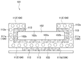
一方、本技術に係る電子機器101が備える両面粘着テープ104は、図4に示すように、前記導電発熱層112の長手方向長さが第一の粘着層111aの長手方向長さと同一に設定され、当該導電発熱層112の両端面が第一の粘着層111aの両端面と同一平面上に配される一方、第二の粘着層111bの端面から突出した構成としても差し支えない。 この形態においては、第一の粘着層111aが前記被着体103と対面する内部電源102の内側面102a、当該内部電源102の両側面102bの一部、前記被覆体と対面する内部電源102の外側面102cに接着されるようにすることが好ましい。
かかる場合、前記導電発熱層112の長手方向長さが第一の粘着層111aの長手方向長さと同一に設定されていることから、前記導電発熱層112は、前記内部電源102の内側面102a、両側面102b及び外側面102cを覆うようにして屈曲し、内部電源102の外側面102c側にて露出するようになる。On the other hand, in the double-sided
In this case, since the longitudinal length of the conductive
次に、以上のように構成された両面粘着テープ104を電子機器101に適用する際の配置例について、図5〜7を用いて説明する。
図5に示すように、前記両面粘着テープ104は、前記内部電源102の長手方向に沿って二つ接着させ、且つ、互いに平行に配置することができる。
また図6に示すように、前記内部電源102の長手方向と垂直な方向に二つ接着させ、且つ、互いに平行に配置することもできる。
更に図7に示すように、内部電源102の長手方向に対して傾斜させて前記両面粘着テープ104を接着させることも可能である。ここで、図7に示す両面粘着テープ104は、図4に示す形態であり、導電発熱層112が内部電源102の外側面102c側に露出している。Next, the example of arrangement | positioning at the time of applying the double-sided
As shown in FIG. 5, two double-sided
In addition, as shown in FIG. 6, two
Further, as shown in FIG. 7, the double-sided pressure-sensitive
(4)駆動回路105
図8に示すように、本技術に係る電子機器101は、当該電子機器101を駆動させるための駆動回路105を備えていてもよい。かかる駆動回路105は、電子機器101に搭載される通常の駆動回路であって、その構成は公知のものを採用することができる。(4)
As illustrated in FIG. 8, the
(5)切り替え部106
図8に示すように、本技術に係る電子機器101は、内部電源102に蓄積されている電気エネルギーの供給先を切り替える切り替え部106を備えていてもよい。この切り替え部106では、電子機器101を駆動させる際、前記内部電源102の電気エネルギーが前記駆動回路105に供給するように構成されている(矢線A及びB)。その一方、前記内部電源102を被着体103から剥離させる際には、前記内部電源102の電気エネルギーが前記両面粘着テープ104の導電発熱層112に供給されるように構成されている(矢線C及びD)。(5)
As illustrated in FIG. 8, the
この切り替え部106の構成は、特に限定されず、回路基盤において電気エネルギーの供給先を切り替える際に用いられる公知のものを適用することができる。例えば、スライドスイッチ、プッシュスイッチ等メカニカルスイッチが挙げられる。
また、切り替え部106を構成する基板パターン部にショートランドを設置し、電子機器101の駆動時は前記駆動回路105側ショートランドをはんだでショートさせて電気エネルギーを供給する一方、内部電源102を剥離する際には前記駆動回路105側のショートランドはんだを除去し、前記導電発熱層112側へのショートランドへはんだ付けを行う構成も挙げられる。
更に、電子機器101の駆動時用の端子やコネクターと、内部電源102の剥離時用の端子やコネクターと、を設け、内部電源102からのフレキシブル配線板又はハーネスの接続先を変更する構成なども挙げられる。The configuration of the
In addition, a short land is installed in the substrate pattern portion constituting the
In addition, there is a configuration in which a terminal or connector for driving the
(6)両面粘着テープの評価
本技術の発明者は、一対の粘着層及び一対の粘着層の間に導電発熱層を有する両面粘着テープを備えた電子機器を製造し、前記導電粘着層を加熱することにより、前記両面粘着テープが被着体から剥離するか否かについての評価を行った。
更に、導電粘着層の熱が粘着層を介して被着体に伝播されるか否かについて評価を行った。
前記両面粘着テープとしては、前記熱発泡剤として、その発泡開始温度が100℃であるものを用い、且つ、この熱発泡剤を各粘着層に含有させたものを製造した。
また、前記電子機器の内部電源としてバッテリを、前記被着体として銅製基板を用いた。更に、前記バッテリの保証温度を85℃と設定した。
そして、前記バッテリと粘着層との界面、及び前記粘着層と導電発熱層との界面に熱電対を設け、加熱時間の経過に応じた各界面における温度変化を測定した。(6) Evaluation of double-sided pressure-sensitive adhesive tape The inventor of the present technology manufactures an electronic device including a double-sided pressure-sensitive adhesive tape having a conductive heat generating layer between a pair of pressure-sensitive adhesive layers and a pair of pressure-sensitive adhesive layers, and heats the conductive pressure-sensitive adhesive layer. Thus, an evaluation was made as to whether or not the double-sided pressure-sensitive adhesive tape was peeled off from the adherend.
Furthermore, it evaluated about whether the heat | fever of a conductive adhesion layer is propagated to a to-be-adhered body through an adhesion layer.
As the double-sided pressure-sensitive adhesive tape, a thermal foaming agent having a foaming start temperature of 100 ° C. and a thermal foaming agent contained in each adhesive layer were produced.
Further, a battery was used as an internal power source of the electronic device, and a copper substrate was used as the adherend. Furthermore, the guaranteed temperature of the battery was set to 85 ° C.
And the thermocouple was provided in the interface of the said battery and the adhesion layer, and the interface of the said adhesion layer and a conductive heat generating layer, and the temperature change in each interface according to progress of heating time was measured.
測定結果を図10に示す。図10において、縦軸は温度を示し、横軸は通電加熱時間(秒)を示す。また、図10中の一点鎖線は熱発泡剤の発泡開始温度を示し、二点鎖線はバッテリの保証温度を示す。更に、四角のプロットが前記バッテリと粘着層との界面における温度を示し、丸のプロットは前記粘着層と導電発熱層との界面における温度を示す。
この図10に示すように、前記導電発熱層を加熱し、前記粘着層と導電発熱層との界面の温度が熱発泡剤の発泡開始温度100℃よりも高温になったとしても、前記バッテリと粘着層との界面の温度はバッテリの保証温度85℃よりも低い温度を示した。
すなわち、本技術に係る両面粘着テープでは、前記バッテリの温度が熱発泡剤の発泡開始温度を下回る温度状態において、当該バッテリを銅製基板から剥離することができる点が確認された。
また、粘着層に含有される熱発泡剤が断熱剤として機能し、導電発熱層から粘着層へと伝播した熱がバッテリに伝播されていないことが確認された。The measurement results are shown in FIG. In FIG. 10, the vertical axis represents temperature, and the horizontal axis represents energization heating time (seconds). Moreover, the dashed-dotted line in FIG. 10 shows the foaming start temperature of a thermal foaming agent, and a dashed-two dotted line shows the guarantee temperature of a battery. Further, a square plot indicates the temperature at the interface between the battery and the adhesive layer, and a circle plot indicates the temperature at the interface between the adhesive layer and the conductive heat generating layer.
As shown in FIG. 10, even when the conductive heat generating layer is heated and the temperature at the interface between the adhesive layer and the conductive heat generating layer becomes higher than the foaming
That is, in the double-sided pressure-sensitive adhesive tape according to the present technology, it was confirmed that the battery can be peeled from the copper substrate in a temperature state where the temperature of the battery is lower than the foaming start temperature of the thermal foaming agent.
Moreover, it was confirmed that the thermal foaming agent contained in the adhesive layer functions as a heat insulating agent, and the heat propagated from the conductive heat generating layer to the adhesive layer is not transmitted to the battery.
以上のような本技術に係る電子機器101によれば、前記内部電源102を被着体103から剥離させる場合、前記粘着層111の端面から突出した導電発熱層112を加熱することにより、当該導電発熱層112が発熱することとなる。これにより、導電発熱層112の熱が粘着層111に伝播し、粘着層111に含有された熱発泡剤113が発泡することとなる。
このため、粘着層111と内部電源102との界面が離間又は内部電源102に対する各粘着層111の接触面積を狭小化させることできる。また、前記熱発泡剤113が発泡することで、前記導電発熱層112の熱が内部電源102に伝播することを防ぐことができる。
その結果、前記内部電源102を被着体103から剥離する際、当該内部電源102の温度上昇を停止させることができ、もって内部電源102の品質劣化を防ぐことができる。According to the
For this reason, the interface between the
As a result, when the
また、本技術に係る電子機器101によれば、前記切り替え部106を備えることにより、当該電子機器101の外部からの電気エネルギーを供給する必要がなく、その分電子機器101を簡易な構成とすることができる。
In addition, according to the
尚、図3や図4に示す両面粘着テープ104では、前記粘着層111が前記導電発熱層112の一面に対して一つ設けられている形態となっているが、前記導電発熱層112に対する粘着層111の数は特に限定されず、複数設けることができる。例えば、図9に示すように、導電発熱層112の一面に対して粘着層111を二つ設けるように構成しても差し支えない。
In the double-sided pressure-sensitive
3.解体構造
本技術は、接着された一対の被着体同士を解体するための構造をも提供する。この解体構造は、両面粘着テープと、前記両面粘着テープを介して接着される一対の被着体と、を備えている。
また、前記両面粘着テープは、一対の粘着層と、一対の粘着層の間に設けられる導電発熱層と、を備えており、一対の粘着層のうち少なくとも一方は、熱発泡剤を含み、前記導電発熱層の端面は、少なくとも一方の粘着層の端面よりも突出している。
そして、本技術に係る解体構造では、前記導電発熱層の端面を加熱することにより、前記熱発泡剤を含む粘着層を発泡膨張させ、一対の被着体を解体させることができる。3. Disassembly structure The present technology also provides a structure for disassembling a pair of adhered adherends. This dismantling structure includes a double-sided pressure-sensitive adhesive tape and a pair of adherends bonded via the double-sided pressure-sensitive adhesive tape.
The double-sided adhesive tape includes a pair of adhesive layers and a conductive heat generating layer provided between the pair of adhesive layers, and at least one of the pair of adhesive layers includes a thermal foaming agent, The end face of the conductive heating layer protrudes from the end face of at least one adhesive layer.
And in the disassembly structure which concerns on this technique, the adhesive layer containing the said thermal foaming agent can be foam-expanded by heating the end surface of the said conductive heat generating layer, and a pair of adherend can be disassembled.
本技術に係る解体構造が備える両面粘着テープの構成は、前述した両面粘着テープ1の構成と同一であるため、ここではその説明を割愛する。
また、本技術に係る解体構造が備える被着体は、前述した両面粘着テープ1が用いられる被着体と同一であるため、ここではその説明を割愛する。Since the structure of the double-sided pressure-sensitive adhesive tape included in the disassembly structure according to the present technology is the same as the structure of the double-sided pressure-sensitive
Moreover, since the adherend with which the disassembly structure which concerns on this technique is provided is the same as the adherend in which the double-sided
4.接着構造
従来、第一の接着体と第二の接着体とが接着された接着構造において、第一の接着体又は第二の接着体を剥離する際には、恒温槽やドライヤーを用いて、前記接着構造全体を加熱する手段が採用されている。
近年、再生資源の再利用の要求が高まる傾向にあり、接着体としてのバッテリ等の内部電源や画像表示面を構成するカバーガラスなどを備える電子機器等において、製造されたバッテリやカバーガラス等を分解して構成材料毎に回収している。
しかし、従来の加熱手段では、第一の接着体及び/又は第二の接着体に対して加熱による損傷を与え、第一の接着体及び/又は第二の接着体を再利用することができないといった課題があった。4). Adhesive structure Conventionally, in the adhesive structure in which the first adhesive body and the second adhesive body are bonded, when peeling the first adhesive body or the second adhesive body, using a thermostatic bath or a dryer, Means for heating the entire adhesive structure is employed.
In recent years, there has been a tendency to increase the demand for reuse of recycled resources. In electronic devices including an internal power source such as a battery as an adhesive or a cover glass constituting an image display surface, the manufactured battery, cover glass, etc. It is disassembled and collected for each component material.
However, in the conventional heating means, the first adhesive body and / or the second adhesive body is damaged by heating, and the first adhesive body and / or the second adhesive body cannot be reused. There was a problem.
本技術は、第一の接着体及び/又は第二の接着体に対して損傷を与えることなく、第一の接着体及び/又は第二の接着体を剥離することができるものであり、第一の接着体と第二の接着体を接着する接着層を有する構造をも提供する。
以下、この接着構造について、図11〜図16を用いて説明する。当該接着構造は、第一の接着体201と、当該第一の接着体に接着される第二の接着体202と、第一の接着体201と第二の接着体202を接着する接着層203と、を少なくとも備える。この接着構造は、必要に応じて、前記接着層203を第一の接着体201又は第二の接着体202から剥離させるための治具204を備えていてもよい。 The present technology is capable of peeling the first adhesive body and / or the second adhesive body without damaging the first adhesive body and / or the second adhesive body. There is also provided a structure having an adhesive layer for adhering one adhesive and a second adhesive.
Hereinafter, this adhesion structure will be described with reference to FIGS. The bonding structure includes a
(1)第一の接着体201及び第二の接着体202
本技術に係る第一の接着体201及び第二の接着体202としては、特に限定されず、公知の接着体を用いることができる。第一の接着体201及び第二の接着体202の組み合わせとしては、携帯電話等を骨格となる筐体と当該筐体に積層され、前記携帯電話の画像表示面を形成するカバーガラスとの組み合わせや、筐体と筐体の貼り合わせ,液晶表示画面と筐体やバックライトの貼り合わせ,基板と筐体の貼り合わせ、また、携帯電話以外の大型電気機器における筐体と筐体の貼り合わせ,筐体と各種デバイスや基板の貼り合わせなどが挙げられる。(1) First
It does not specifically limit as the 1st
(2)接着層203
本技術に係る接着構造は、前記第一の接着体201と第二の接着体202とを接着させるための接着層203を備える。この接着層203を成形するための接着剤としては特に限定されず、公知の接着剤を用いることができる。また、この接着層203の全部又は一部は、自己解体性接着層205として形成されており、この自己解体性接着層205は前記第一の接着体201又は第二の接着体202の少なくとも一方に接している。図11に示す形態では、前記接着層203の全部が自己解体性接着層205として形成され、且つ、当該接着層が第一の接着体201と第二の接着体202との間に配されている例を示している。(2)
The adhesive structure according to the present technology includes an
ここで、自己解体性接着層205とは、自ら前記第一の接着体201及び/又は第二の接着体202から剥離する接着層をいい、例えば、熱発泡剤206を含む接着層等が挙げられる。前記熱発泡剤206としては、特に限定されず、例えば公知の熱発泡剤を適宜選択して用いることができ、例えば、マイクロカプセル化された発泡剤や、種々の無機系発泡剤や有機系発泡剤が挙げられる。マイクロカプセル化された発泡剤の例としては、ポリ塩化ビニルやポリビニリデン等からなる殻内に、液化炭化水素などが充填され、前記液化炭素水素が加熱により容易にガス化して膨脹するようなものが挙げられる。また、無機系発泡剤の代表例としては、炭酸アンモニウム、炭酸水素アンモニウム、炭酸水素ナトリウム等が挙げられ、有機系発泡剤の代表例としては、ジクロロモノフルオロメタン等の塩フッ化アルカン;アゾビスイソブチロニトリル等のアゾ系化合物等が挙げられる。
Here, the self-disassembling
また、前記熱発泡剤206の発泡開始温度は、第一の接着体201及び/又は第二の接着体202の製品信頼性保証条件以上の温度(以下、「保証温度」という)よりも高く設定されていることが好ましい。
加えて、前記熱発泡剤13の発泡開始温度は、第一の接着体201及び/又は第二の接着体202の製品信頼性保証条件を確保しつつも、当該熱発泡剤206が断熱剤として機能させる必要があることから、前記被着体の保証温度に対して余裕度を確保しながら極力低い温度に設定することが好ましい。
より具体的には、第一の接着体201及び/又は第二の接着体202の保証温度よりも10〜50℃の範囲で高く設定されていることが好ましく、より好ましくは10〜30℃の範囲で高く設定する。The foaming start temperature of the
In addition, the foaming start temperature of the
More specifically, it is preferably set higher in the range of 10 to 50 ° C. than the guaranteed temperature of the first
(3)治具204
本技術に係る接着構造では、前記自己解体性接着層205を加熱することにより、当該自己解体性接着層205に含有された熱発泡剤206が発泡し、接着層203が自ら第一の接着体201及び/又は第二の接着体202から剥離するようになっている。
前記自己解体性接着層205を加熱する方法としては、特に限定されず、治具を用いて直接通電して発熱させる方法や高周波による電磁誘導を利用した方法等が挙げられる。(3)
In the adhesive structure according to the present technology, by heating the self-disassembling
The method for heating the self-decomposing
本技術に係る接着構造は、前記自己解体性接着層205を加熱するための治具204を備えていてもよい。この治具204は、対象物に対して熱を加える治具であれば特に限定されず、公知の治具を用いることができる。本技術に係る治具204としては、前記自己解体性接着層205に挿入される加熱部と、当該加熱部に電気エネルギーを供給するための内部電源と、を少なくとも備えるものが挙げられる。
The adhesive structure according to the present technology may include a
前記加熱部は、例えば、細い棒状又は針状の金属材から形成されており、前記内部電源から電気エネルギーが供給される構成となっている。そして、前記加熱部は、前記内部電源から供給される電気エネルギーにより発熱する。このような加熱部を形成する金属部材としては、熱伝導率が高い材料を用いることが好ましく、例えば、銅、真鍮、アルミニウム等が挙げられる。更に、前記加熱部を加熱するための構造としては、当該加熱部に対してニクロム線等の通電発熱物を巻き付ける構造や、ガスにより燃焼させる構造等が挙げられる。 The heating unit is made of, for example, a thin rod-shaped or needle-shaped metal material, and is configured to be supplied with electrical energy from the internal power source. The heating unit generates heat by electric energy supplied from the internal power source. As a metal member that forms such a heating unit, it is preferable to use a material having high thermal conductivity, and examples thereof include copper, brass, and aluminum. Furthermore, examples of the structure for heating the heating unit include a structure in which an energized heating material such as a nichrome wire is wound around the heating unit, and a structure in which the heating unit is burned with gas.
また、細い棒状又は針状に形成された加熱部の先端部は、自己解体性接着層205を加熱することができる構成であればよく、例えば自己解体性接着層205の表面のみを加熱する場合には、先端部が平面状に形成された構成であってもよい。あるいは、先端部を自己解体性接着層205に差し込んで加熱する場合には尖頭状に形成されていることが好ましい。
ここで、前記自己解体性接着層205に含有される熱発泡剤206を確実に発泡させるためには、前記先端部を尖頭状とし、自己解体性接着層205の内部に加熱部を差し込むことが好ましい。In addition, the tip of the heating part formed in a thin rod shape or needle shape may be configured so as to heat the self-disassembling
Here, in order to surely foam the
以上のように構成された本技術に係る接着構造によれば、自己解体性接着層205を加熱することにより、当該自己解体性接着層205に含有された熱発泡剤206が発泡し、接着層203が自ら第一の接着体201及び/又は第二の接着体202から剥離するようになっている。このため、従来のように、接着構造全体を加熱する必要がなく、第一の接着体201及び/又は第二の接着体202に対して損傷を与えることなく、第一の接着体201及び/又は第二の接着体202を剥離することができる。その結果、第一の接着体201及び/又は第二の接着体202を再利用することができる。
According to the adhesive structure according to the present technology configured as described above, by heating the self-dismantling
ここで、図11に示す形態に係る接着構造では、前記接着層203の全体が自己解体性接着層205として形成されているが、当該接着層203の構成はこれに限定されない。
すなわち、第一の接着体201及び/又は第二の接着体202に対して接着層203を自ら剥離させる契機を与えることができればよく、前述の如く、前記接着層203の一部を前記自己解体性接着層205とすることができる。
かかる場合には、自己解体性接着層205以外の接着剤として硬度が高いものを用いることにより接着層203全体の強度を向上させるができる。また、自己解体性接着層205以外の接着剤を公知の接着剤とすることにより、接着層203全体を安価に製造することができる。Here, in the adhesive structure according to the embodiment shown in FIG. 11, the entire
That is, it is sufficient that the first
In such a case, the strength of the
次に、本技術に係る接着構造の第二の実施形態について、図12を用いて説明する。この第二の実施形態に係る接着構造は、第一の接着体201の構造が第一の実施形態に係る第一の接着体と異なる。一方で、他の構成については共通するため、ここでは他の構成に関する説明は割愛する。
すなわち、この第二の実施形態に係る接着構造では、前記治具204が挿入される治具挿入孔207が第一の接着体201に形成されている。前記治具挿入孔207は全部が自己解体性接着層205である接着層203に向けて開口されている。Next, a second embodiment of the adhesive structure according to the present technology will be described with reference to FIG. The bonding structure according to the second embodiment is different from the first bonding body according to the first embodiment in the structure of the
That is, in the bonding structure according to the second embodiment, a
この第二の実施形態に係る接着構造によれば、前記治具挿入孔207に治具204を挿入し、当該治具204を用いて接着層203(自己解体性接着層205)を加熱することができる。その結果、該自己解体性接着層205に含有された熱発泡剤206が発泡し、接着層203が自ら第一の接着体201及び/又は第二の接着体202から剥離するようになっている。このため、従来のように、接着構造全体を加熱する必要がなく、第一の接着体201及び/又は第二の接着体202に対して損傷を与えることなく、剥離することができる。その結果、第一の接着体201及び/又は第二の接着体202を再利用することができる。
また、携帯電話等の電子機器内の接着構造として本技術を適用する場合、図11に示すように、自己解体性接着層205を接着構造の左右から加熱することが困難となり得る。かかる場合には、前記治具挿入孔207を設けることにより、前記自己解体性接着層205を加熱することができる。According to the adhesive structure according to the second embodiment, the
In addition, when the present technology is applied as an adhesive structure in an electronic device such as a mobile phone, it may be difficult to heat the self-disassembling
尚、図12に示す接着構造では、第一の接着体201に対して前記治具挿入孔207が形成されているが、当該治具挿入孔207は第一の接着体201又は第二の接着体202の少なくとも一方に形成されていれば差し支えない。また、図12に示す接着構造では、第一の接着体201に対して治具挿入孔207が一つ形成されているが、当該治具挿入孔207の数は限定されず、接着体201,202に対して複数形成されていてもよい。
更に、図12に示す接着構造では、前記接着層203全体が自己解体性接着層205として形成されているが、第一の接着体201及び/又は第二の接着体202に対して接着層203を自ら剥離させる契機を与えることができればよく、図13に示すように、前記治具挿入孔207と連続する接着層203の一部を前記自己解体性接着層205として形成しても差し支えない。 In the bonding structure shown in FIG. 12, the
Furthermore, in the adhesive structure shown in FIG. 12, the entire
次に、本技術に係る接着構造の第三実施形態について、図14を用いて説明する。この第三の実施形態に係る接着構造では、接着層203の配置が図11に示す第一の実施形態に係る接着層の配置と異なる。一方で、他の構成については共通するため、ここでは他の構成に関する説明は割愛する。
すなわち、この第三の実施形態に係る接着構造では、第一の接着体201の両端面と第二の接着体202の両端面に対して接着層203が設けられ、第一の接着体201と第二の接着体202とが所謂ポッティング接着されている。
そして、各接着層203は全部が自己解体性接着層205として形成されている。Next, a third embodiment of the adhesive structure according to the present technology will be described with reference to FIG. In the adhesive structure according to the third embodiment, the arrangement of the
That is, in the adhesive structure according to the third embodiment, the
Each
このような第三の実施形態に係る接着構造によれば、自己解体性接着層205を加熱することにより、当該自己解体性接着層205に含有された熱発泡剤206が発泡し、接着層203が自ら第一の接着体201及び/又は第二の接着体202から剥離するようになっている。このため、従来のように、接着構造全体を加熱する必要がなく、第一の接着体201及び/又は第二の接着体202に対して損傷を与えることなく、剥離することができる。その結果、第一の接着体201及び/又は第二の接着体202を再利用することができる。
According to the adhesive structure according to the third embodiment, by heating the self-decomposing
ここで、図14に示す接着構造では、前記接着層203の全体が自己解体性接着層205として形成されているが、当該接着層203の構成はこれに限定されず、第一の接着体201及び/又は第二の接着体202に対して接着層203を自ら剥離させる契機を与えることができればよく、前記接着層203の一部を前記自己解体性接着層205としても差し支えない。
図14に示す接着構造では、第一の接着体201と第二の接着体202とが所謂ポッティング接着されている。この構成において前記接着層203の一部を前記自己解体性接着層205にする場合、第一の接着体201と第二の接着体202と確実に剥離させるため、自己解体性接着層205は、図15に示すように、第一の接着体201と第二の接着体202との界面上に配置されることが好ましい。
このような構成とした場合、第一の接着体201と第二の接着体202と確実に剥離させることができる。また、自己解体性接着層205以外の接着剤として硬度が高いものを用いることにより接着層203全体の強度を向上させるができる。また、自己解体性接着層205以外の接着剤を公知の接着剤とすることにより、接着層203全体を安価に製造することができる。Here, in the adhesive structure shown in FIG. 14, the entire
In the bonding structure shown in FIG. 14, the
In such a configuration, the first
次に、本技術に係る接着構造の第四実施形態について、図16を用いて説明する。この第四の実施形態に係る接着構造では、第一の接着体201と第二の接着体202との接着方法、及び第一の接着体201の構造が図13に示す接着構造と異なる。一方で、他の構成については共通するため、ここでは同一の符号を付してその説明は割愛する。
Next, a fourth embodiment of the bonding structure according to the present technology will be described with reference to FIG. In the bonding structure according to the fourth embodiment, the bonding method between the
この第四の実施形態に係る接着構造では、第一の接着体201と第二の接着体202とが接着層203及び自己解体性接着層205を介して接着されている。第一の接着体201の両端面と第二の接着体202の両端面に対して接着層203が設けられ、第一の接着体201と第二の接着体202とが所謂ポッティング接着されている。
更に、第一の接着体201と第二の接着体202との界面上に接着層203が設けられ、当該接着層203が自己解体性接着層205として形成されている。
また、前記第一の接着体201には、前記自己解体性接着層205に連通する治具挿入孔207が形成されており、当該治具挿入孔207には前記治具204が挿入されるようになっている。In the bonding structure according to the fourth embodiment, the
Further, an
In addition, a
このような第四の実施形態に係る接着構造によれば、自己解体性接着層205を加熱することにより、当該自己解体性接着層205に含有された熱発泡剤206が発泡し、第一の接着体201と第二の接着体202とを互いに剥離することができる。このため、従来のように、接着構造全体を加熱する必要がなく、第一の接着体201及び/又は第二の接着体202に対して損傷を与えることなく、剥離することができる。その結果、第一の接着体201及び/又は第二の接着体202を再利用することができる。
According to such an adhesive structure according to the fourth embodiment, by heating the self-decomposing
本技術は、以下のような構成をとることもできる。
(1)
一対の粘着層と、前記一対の粘着層の間に設けられる導電発熱層と、を備え、
前記一対の粘着層のうち少なくとも一方は、熱発泡剤を含み、
前記導電発熱層の端面は、少なくとも一方の前記粘着層の端面よりも突出する、両面粘着テープ。
(2)
前記熱発泡剤の発泡開始温度は、前記粘着層に接着される被着体の保証温度よりも高く設定され、
前記導電発熱層の発熱温度は、前記発泡開始温度と同一又は高く設定される、(1)に記載の両面粘着テープ。
(3)
前記導電発熱層の端面は、一方の前記粘着層の端面よりも突出し、他方の粘着層の端面と同一平面上に配される、(1)又は(2)に記載の両面粘着テープ。
(4)
各粘着層が熱発泡剤を含む、(1)〜(3)の何れか一つに記載の両面粘着テープ。
(5)
電子機器を駆動させる内部電源と、前記内部電源と接着する被着体と、前記内部電源と被着体とを接着する両面粘着テープと、を少なくとも備える電子機器であって、
前記両面粘着テープは、前記内部電源に接着される第一の粘着層と、前記被着体に接着される第二の粘着層と、前記第一の粘着層と前記第二の粘着層の間に設けられる導電発熱層と、を備え、
前記第一の粘着層又は前記第二の粘着層のいずれか一方は、熱発泡剤を含み、
前記導電発熱層の端面は、前記第一の粘着層又は前記第二の粘着層のいずれか一方の粘着層の端面よりも突出する、電子機器。
(6)
前記両面粘着テープに含有される熱発泡剤の発泡開始温度は、前記内部電源の保証温度よりも高く設定され、
前記導電発熱層の発熱温度は、前記発泡開始温度と同一又は高く設定される、(5)に記載の電子機器。
(7)
前記導電発熱層の端面は、前記第二の粘着層の端面よりも突出し、前記第一の粘着層の端面と同一平面上に配される、(5)又は(6)に記載の電子機器。
(8)
前記第一の粘着層は熱発泡剤を含む、(5)〜(7)の何れか一つに記載の電子機器。(9)
前記第一の粘着層は、前記被着体と対面する内部電源の内側面、及び前記内部電源を覆う被覆体と対面する当該内部電源の外側面、に接着される、(5)〜(8)の何れか一つに記載の電子機器。
(10)
更に、前記内部電源から前記電子機器へと供給される電気エネルギーを前記導電発熱層へと供給する切り替え部を備える、(5)〜(9)の何れか一つに記載の電子機器。
(11)
両面粘着テープと、
前記両面粘着テープを介して接着される一対の被着体と、を備え、
前記両面粘着テープは、一対の粘着層と、前記一対の粘着層の間に設けられる導電発熱層と、を備え、
前記一対の粘着層のうち少なくとも一方は、熱発泡剤を含み、
前記導電発熱層の端面は、少なくとも一方の前記粘着層の端面よりも突出し、
前記導電発熱層の端面を加熱することにより、前記熱発泡剤を含む粘着層を発泡膨張させて前記一対の被着体を解体させる解体構造。
(12)
第一の接着体と第二の接着体とを接着する接着層を有する接着構造であって、
前記接着層は、前記第一の接着体又は前記第二の接着体の少なくとも一方に接する自己解体性接着層を有する、接着構造。
(13)
前記第一の接着体又は前記第二の接着体の少なくとも一方には、前記自己解体性接着層に連通する治具挿入孔が形成されている、(12)に記載の接着構造。
This technology can also take the following composition.
(1)
Comprising a pair of adhesive layers, and a conductive heat-generating layer provided between the pair of adhesive layers,
At least one of the pair of adhesive layers includes a thermal foaming agent,
The end surface of the electric heating layer projects from the end face of at least one of the adhesive layers, double-sided adhesive tape.
(2)
The foaming start temperature of the thermal foaming agent is set higher than the guaranteed temperature of the adherend bonded to the adhesive layer,
The double-sided pressure-sensitive adhesive tape according to (1), wherein the heat generation temperature of the conductive heat generation layer is set equal to or higher than the foaming start temperature.
(3)
(2) The double-sided pressure-sensitive adhesive tape according to (1) or (2), wherein an end face of the conductive heating layer protrudes from an end face of one of the pressure-sensitive adhesive layers and is arranged on the same plane as the end face of the other pressure-sensitive adhesive layer.
(4)
The double-sided pressure-sensitive adhesive tape according to any one of (1) to (3), wherein each pressure-sensitive adhesive layer contains a thermal foaming agent.
(5)
An electronic device comprising at least an internal power source that drives the electronic device, an adherend that adheres to the internal power source, and a double-sided adhesive tape that adheres the internal power source and the adherend,
The double-sided adhesive tape, between the and the first adhesive layer adhered to the internal power supply, said a second adhesive layer adhered to the adherend, the first adhesive layer and said second adhesive layer A conductive heating layer provided on
One of the first adhesive layer or the second adhesive layer comprises a blowing agent,
The end surface of the electric heating layer projects from the end face of one of the pressure-sensitive adhesive layer of the first adhesive layer or the second adhesive layer, the electronic device.
(6)
The foaming start temperature of the thermal foaming agent contained in the double-sided pressure-sensitive adhesive tape is set higher than the guaranteed temperature of the internal power supply,
The electronic device according to (5), wherein the heat generation temperature of the conductive heat generation layer is set equal to or higher than the foaming start temperature.
(7)
The end face of the conductive heat generating layer projects from the end face of the second adhesive layer, and is disposed on the same plane as the end face of the first adhesive layer. The electronic device according to (5) or (6).
(8)
The electronic device according to any one of (5) to (7), wherein the first adhesive layer includes a thermal foaming agent. (9)
The first adhesive layer is bonded to the inner side surface of the internal power source facing the adherend and the outer side surface of the internal power source facing the covering covering the internal power source, (5) to (8 ) The electronic device according to any one of
(10)
The electronic device according to any one of (5) to (9), further including a switching unit that supplies electric energy supplied from the internal power source to the electronic device to the conductive heat generation layer.
(11)
Double-sided adhesive tape,
A pair of adherends bonded via the double-sided adhesive tape,
The double-sided adhesive tape is provided with a pair of adhesive layers, and a conductive heat-generating layer provided between the pair of adhesive layers,
At least one of the pair of adhesive layers includes a thermal foaming agent,
The end surface of the electric heating layer protrudes from the end surface of at least one of the adhesive layer,
Wherein by heating the end surface of the electric heating layer, dismantle the structure of the adhesive layer by foaming expansion to dismantle the pair of adherends including the thermal foaming agent.
(12)
An adhesive structure having an adhesive layer that bonds the first adhesive body and the second adhesive body,
The adhesive layer has a self-dismantling adhesive layer in contact with at least one of the first adhesive body or the second adhesive body, the adhesive structure.
(13)
The first at least one of the adhesive body or the second adhesive body, the jig insertion hole communicating with the self-dismantling adhesive layer is formed, the adhesion structure according to (12).
1,104 両面粘着テープ
11,111,111a,111b 粘着層
12,112 導電発熱層
13,113 熱発泡剤
101 電子機器
102 内部電源
103 被着体DESCRIPTION OF SYMBOLS 1,104 Double-sided adhesive tape 11,111,111a, 111b Adhesive layer 12,112 Conductive heat generating layer 13,113
Claims (11)
前記一対の粘着層のうち少なくとも一方は、熱発泡剤を含み、
前記導電発熱層の端面は、少なくとも一方の前記粘着層の端面よりも突出する、両面粘着テープ。 Comprising a pair of adhesive layers, and a conductive heat-generating layer provided between the pair of adhesive layers,
At least one of the pair of adhesive layers includes a thermal foaming agent,
The end surface of the electric heating layer projects from the end face of at least one of the adhesive layers, double-sided adhesive tape.
前記導電発熱層の発熱温度は、前記発泡開始温度と同一又は高く設定される、請求項1に記載の両面粘着テープ。 The foaming start temperature of the thermal foaming agent is set higher than the guaranteed temperature of the adherend bonded to the adhesive layer,
The double-sided pressure-sensitive adhesive tape according to claim 1, wherein the heat generation temperature of the conductive heat generation layer is set equal to or higher than the foaming start temperature.
前記両面粘着テープは、前記内部電源に接着される第一の粘着層と、前記被着体に接着される第二の粘着層と、前記第一の粘着層と前記第二の粘着層の間に設けられる導電発熱層と、を備え、
前記第一の粘着層又は前記第二の粘着層のいずれか一方は、熱発泡剤を含み、
前記導電発熱層の端面は、前記第一の粘着層又は前記第二の粘着層のいずれか一方の粘着層の端面よりも突出する、電子機器。 An electronic device comprising at least an internal power source that drives the electronic device, an adherend that adheres to the internal power source, and a double-sided adhesive tape that adheres the internal power source and the adherend,
The double-sided adhesive tape, between the and the first adhesive layer adhered to the internal power supply, said a second adhesive layer adhered to the adherend, the first adhesive layer and said second adhesive layer A conductive heating layer provided on
One of the first adhesive layer or the second adhesive layer comprises a blowing agent,
The end surface of the electric heating layer projects from the end face of one of the pressure-sensitive adhesive layer of the first adhesive layer or the second adhesive layer, the electronic device.
前記導電発熱層の発熱温度は、前記発泡開始温度と同一又は高く設定される、請求項5に記載の電子機器。 The foaming start temperature of the thermal foaming agent contained in the double-sided pressure-sensitive adhesive tape is set higher than the guaranteed temperature of the internal power supply,
The electronic device according to claim 5, wherein a heat generation temperature of the conductive heat generation layer is set equal to or higher than the foaming start temperature.
前記両面粘着テープを介して接着される一対の被着体と、を備え、
前記両面粘着テープは、一対の粘着層と、前記一対の粘着層の間に設けられる導電発熱層と、を備え、
前記一対の粘着層のうち少なくとも一方は、熱発泡剤を含み、
前記導電発熱層の端面は、少なくとも一方の前記粘着層の端面よりも突出し、
前記導電発熱層の端面を加熱することにより、前記熱発泡剤を含む粘着層を発泡膨張させて前記一対の被着体を解体させる解体構造。 Double-sided adhesive tape,
A pair of adherends bonded via the double-sided adhesive tape,
The double-sided adhesive tape is provided with a pair of adhesive layers, and a conductive heat-generating layer provided between the pair of adhesive layers,
At least one of the pair of adhesive layers includes a thermal foaming agent,
The end surface of the electric heating layer protrudes from the end surface of at least one of the adhesive layer,
Wherein by heating the end surface of the electric heating layer, dismantle the structure of the adhesive layer by foaming expansion to dismantle the pair of adherends including the thermal foaming agent.
Priority Applications (1)
| Application Number | Priority Date | Filing Date | Title |
|---|---|---|---|
| JP2017245089A JP6973032B2 (en) | 2015-07-21 | 2017-12-21 | Double-sided adhesive tape, electronic device equipped with the double-sided adhesive tape, dismantling structure including the double-sided adhesive tape, adhesive structure |
Applications Claiming Priority (3)
| Application Number | Priority Date | Filing Date | Title |
|---|---|---|---|
| JP2015144213 | 2015-07-21 | ||
| JP2015144213 | 2015-07-21 | ||
| PCT/JP2016/062477 WO2017013914A1 (en) | 2015-07-21 | 2016-04-20 | Double-sided adhesive tape, electronic instrument propided with said double-sided adhesive tape, disassembly structure provided with said double-sided adhesive tape, and adhered structure |
Related Child Applications (1)
| Application Number | Title | Priority Date | Filing Date |
|---|---|---|---|
| JP2017245089A Division JP6973032B2 (en) | 2015-07-21 | 2017-12-21 | Double-sided adhesive tape, electronic device equipped with the double-sided adhesive tape, dismantling structure including the double-sided adhesive tape, adhesive structure |
Publications (2)
| Publication Number | Publication Date |
|---|---|
| JPWO2017013914A1 JPWO2017013914A1 (en) | 2017-12-07 |
| JP6264509B2 true JP6264509B2 (en) | 2018-01-24 |
Family
ID=57834286
Family Applications (2)
| Application Number | Title | Priority Date | Filing Date |
|---|---|---|---|
| JP2017529476A Active JP6264509B2 (en) | 2015-07-21 | 2016-04-20 | Double-sided pressure-sensitive adhesive tape, electronic device including the double-sided pressure-sensitive adhesive tape, disassembly structure including the double-sided pressure-sensitive adhesive tape, adhesive structure |
| JP2017245089A Active JP6973032B2 (en) | 2015-07-21 | 2017-12-21 | Double-sided adhesive tape, electronic device equipped with the double-sided adhesive tape, dismantling structure including the double-sided adhesive tape, adhesive structure |
Family Applications After (1)
| Application Number | Title | Priority Date | Filing Date |
|---|---|---|---|
| JP2017245089A Active JP6973032B2 (en) | 2015-07-21 | 2017-12-21 | Double-sided adhesive tape, electronic device equipped with the double-sided adhesive tape, dismantling structure including the double-sided adhesive tape, adhesive structure |
Country Status (5)
| Country | Link |
|---|---|
| US (1) | US11306223B2 (en) |
| JP (2) | JP6264509B2 (en) |
| CN (1) | CN107835844A (en) |
| DE (1) | DE112016003292B4 (en) |
| WO (1) | WO2017013914A1 (en) |
Families Citing this family (6)
| Publication number | Priority date | Publication date | Assignee | Title |
|---|---|---|---|---|
| JP6788304B2 (en) * | 2017-11-13 | 2020-11-25 | 株式会社朝日Fr研究所 | Thermoelectric converter |
| US20210175536A1 (en) * | 2017-12-18 | 2021-06-10 | Samsung Sdi Co., Ltd. | Finishing tape and secondary battery comprising same |
| CN109971387B (en) * | 2017-12-28 | 2021-01-22 | 清华大学 | Application of carbon nanotube structure as double-sided adhesive tape |
| KR102270269B1 (en) * | 2018-01-17 | 2021-06-28 | 주식회사 엘지에너지솔루션 | Battery module housing having a reusable, recyclable or reworkable adhesive structure and Battery module the same |
| US11084955B2 (en) * | 2018-07-23 | 2021-08-10 | Microsoft Technology Licensing, Llc | Pressure sensitive adhesive with thermally conductive release tab |
| CN112787033A (en) * | 2021-01-29 | 2021-05-11 | 东莞新能德科技有限公司 | Thermal anti-sticking protective film and electronic device using same |
Family Cites Families (20)
| Publication number | Priority date | Publication date | Assignee | Title |
|---|---|---|---|---|
| SE439599B (en) * | 1981-01-14 | 1985-06-24 | Kema Nord Ab | WAY TO DRY AND EXPAND IN LIQUID DISPERSED, THERMOPLASTIC MICROSPHERES CONTAINING, VOLTABLE, LIQUID JEWELERY |
| JPH04198289A (en) | 1990-11-26 | 1992-07-17 | Sekisui Chem Co Ltd | Preparation of single-side or double-side adhesive foam tape |
| JP3452972B2 (en) | 1994-04-08 | 2003-10-06 | 三福工業株式会社 | Method for producing fluororubber foam |
| JPH11293207A (en) | 1998-04-03 | 1999-10-26 | Nitto Denko Corp | Thermally eliminable pressure-sensitive adhesive sheet |
| JP2001323228A (en) * | 2000-05-15 | 2001-11-22 | Nitto Denko Corp | Heat release adhesive sheet |
| JP2004099758A (en) * | 2002-09-10 | 2004-04-02 | Nitto Denko Corp | Double-sided adhesive tape and adhesion process |
| JP2005101094A (en) | 2003-09-22 | 2005-04-14 | Sekisui Chem Co Ltd | Substrate having circuit pattern formed on its surface, ceramic green sheet having sinterability, and method of manufacturing multilayered ceramic substrate |
| JP4704017B2 (en) * | 2004-12-09 | 2011-06-15 | 日東電工株式会社 | Heat-peeling method for adherend and heat-peeling apparatus for adherend |
| JP2007023113A (en) | 2005-07-14 | 2007-02-01 | Asahi Kasei Chemicals Corp | Double-sided adhesive film, method for adhesion and bonded structure |
| JP5171425B2 (en) | 2007-10-22 | 2013-03-27 | 日東電工株式会社 | Heat-foaming type removable acrylic pressure-sensitive adhesive tape or sheet, and peeling method |
| JP5173753B2 (en) | 2008-11-11 | 2013-04-03 | 日東電工株式会社 | Dismantling structure, electrical and non-electrical equipment having dismantling structure, and disassembling method |
| JP5546985B2 (en) | 2010-07-28 | 2014-07-09 | 日東電工株式会社 | Semiconductor device manufacturing film, semiconductor device manufacturing film manufacturing method, and semiconductor device manufacturing method. |
| JP2012117041A (en) | 2010-11-12 | 2012-06-21 | Nitto Denko Corp | Pressure-sensitive adhesive composition, pressure-sensitive adhesive layer, and pressure-sensitive adhesive tape or sheet |
| JP2013045036A (en) * | 2011-08-26 | 2013-03-04 | Seiko Instruments Inc | Adhesive label and label issuing device |
| JP2013133464A (en) | 2011-12-27 | 2013-07-08 | Nitto Denko Corp | Pressure-sensitive adhesive sheet for glass plate |
| JP2013159743A (en) | 2012-02-07 | 2013-08-19 | Nitto Denko Corp | Method for peeling pressure-sensitive adhesive agent laminate and pressure-sensitive adhesive agent layer used therein |
| US20140287299A1 (en) * | 2013-03-25 | 2014-09-25 | Apple Inc. | Heat-Debonding Adhesives |
| JP2015034265A (en) * | 2013-08-09 | 2015-02-19 | 日東電工株式会社 | Easy-dismantlement type double-sided adhesive sheet, and adhesion method thereof |
| CN103474596B (en) * | 2013-09-16 | 2016-01-13 | 惠州Tcl移动通信有限公司 | A kind of fixture of mobile terminal soft-package battery, fixing means and mobile terminal |
| JP6376741B2 (en) * | 2013-10-11 | 2018-08-22 | アキレス株式会社 | Thermally peelable adhesive film |
-
2016
- 2016-04-20 JP JP2017529476A patent/JP6264509B2/en active Active
- 2016-04-20 WO PCT/JP2016/062477 patent/WO2017013914A1/en active Application Filing
- 2016-04-20 CN CN201680012920.2A patent/CN107835844A/en active Pending
- 2016-04-20 DE DE112016003292.7T patent/DE112016003292B4/en active Active
- 2016-04-20 US US15/554,165 patent/US11306223B2/en active Active
-
2017
- 2017-12-21 JP JP2017245089A patent/JP6973032B2/en active Active
Also Published As
| Publication number | Publication date |
|---|---|
| WO2017013914A1 (en) | 2017-01-26 |
| US11306223B2 (en) | 2022-04-19 |
| JPWO2017013914A1 (en) | 2017-12-07 |
| CN107835844A (en) | 2018-03-23 |
| DE112016003292B4 (en) | 2024-03-28 |
| JP6973032B2 (en) | 2021-11-24 |
| JP2018087335A (en) | 2018-06-07 |
| DE112016003292T5 (en) | 2018-04-12 |
| US20180291237A1 (en) | 2018-10-11 |
Similar Documents
| Publication | Publication Date | Title |
|---|---|---|
| JP6264509B2 (en) | Double-sided pressure-sensitive adhesive tape, electronic device including the double-sided pressure-sensitive adhesive tape, disassembly structure including the double-sided pressure-sensitive adhesive tape, adhesive structure | |
| US20140287299A1 (en) | Heat-Debonding Adhesives | |
| JP5175746B2 (en) | Multilayer flexible circuit board | |
| CN106133812A (en) | Display device, display module and display member | |
| CN101742190A (en) | Disassemblable structure, electric equipment and non-electric equipment having disassemblable structure, and disassembling method | |
| CN109799876B (en) | Terminal device and method of controlling the same | |
| JP2007027222A (en) | Flexible printed circuit board | |
| CN113692130A (en) | FPC structure and manufacturing method thereof | |
| CN106255317A (en) | A kind of convenient splicing durable type HDI flexible circuit board and processing technique thereof | |
| CN107801303B (en) | Flexible circuit board | |
| JP2017204514A (en) | Electronic apparatus and dismantling method thereof | |
| TW200626040A (en) | Thermal bonding structure and manufacture process of flexible printed circuit (FPC) | |
| WO2020026661A1 (en) | Display device and method for radiating heat | |
| JP5525017B2 (en) | Non-electric equipment having a dismantling structure and a dismantling structure | |
| JPWO2007023534A1 (en) | Display panel device | |
| JP4202295B2 (en) | Reflow soldering equipment | |
| CN104075179A (en) | Backlight module and display device comprising same | |
| CN215647605U (en) | FPC structure | |
| CN209676599U (en) | One kind can weld concatenated flexible circuit board | |
| JP2005051177A (en) | Flexible wiring board | |
| KR101156647B1 (en) | Method for fabricating a Multi-layer MCCL PCB | |
| JP2007027221A (en) | Flexible printed circuit board | |
| JP4985927B2 (en) | Display device | |
| JP2007307937A (en) | Vehicular display device | |
| JP2009246081A (en) | Terminal structure using flexible circuit board |
Legal Events
| Date | Code | Title | Description |
|---|---|---|---|
| A521 | Request for written amendment filed |
Free format text: JAPANESE INTERMEDIATE CODE: A523 Effective date: 20171019 |
|
| A621 | Written request for application examination |
Free format text: JAPANESE INTERMEDIATE CODE: A621 Effective date: 20171019 |
|
| A871 | Explanation of circumstances concerning accelerated examination |
Free format text: JAPANESE INTERMEDIATE CODE: A871 Effective date: 20171019 |
|
| A975 | Report on accelerated examination |
Free format text: JAPANESE INTERMEDIATE CODE: A971005 Effective date: 20171115 |
|
| TRDD | Decision of grant or rejection written | ||
| A01 | Written decision to grant a patent or to grant a registration (utility model) |
Free format text: JAPANESE INTERMEDIATE CODE: A01 Effective date: 20171121 |
|
| A61 | First payment of annual fees (during grant procedure) |
Free format text: JAPANESE INTERMEDIATE CODE: A61 Effective date: 20171204 |
|
| R151 | Written notification of patent or utility model registration |
Ref document number: 6264509 Country of ref document: JP Free format text: JAPANESE INTERMEDIATE CODE: R151 |