JP6263760B2 - Game machine - Google Patents

Game machine Download PDF

Info

Publication number
JP6263760B2
JP6263760B2 JP2015219605A JP2015219605A JP6263760B2 JP 6263760 B2 JP6263760 B2 JP 6263760B2 JP 2015219605 A JP2015219605 A JP 2015219605A JP 2015219605 A JP2015219605 A JP 2015219605A JP 6263760 B2 JP6263760 B2 JP 6263760B2
Authority
JP
Japan
Prior art keywords
light emitting
game
emitting member
emitting members
game ball
Prior art date
Legal status (The legal status is an assumption and is not a legal conclusion. Google has not performed a legal analysis and makes no representation as to the accuracy of the status listed.)
Active
Application number
JP2015219605A
Other languages
Japanese (ja)
Other versions
JP2016026831A (en
JP2016026831A5 (en
Inventor
田中 勝巳
勝巳 田中
Original Assignee
株式会社サンセイアールアンドディ
Priority date (The priority date is an assumption and is not a legal conclusion. Google has not performed a legal analysis and makes no representation as to the accuracy of the date listed.)
Filing date
Publication date
Application filed by 株式会社サンセイアールアンドディ filed Critical 株式会社サンセイアールアンドディ
Priority to JP2015219605A priority Critical patent/JP6263760B2/en
Publication of JP2016026831A publication Critical patent/JP2016026831A/en
Publication of JP2016026831A5 publication Critical patent/JP2016026831A5/ja
Application granted granted Critical
Publication of JP6263760B2 publication Critical patent/JP6263760B2/en
Active legal-status Critical Current
Anticipated expiration legal-status Critical

Links

Images

Landscapes

  • Pinball Game Machines (AREA)
  • Display Devices Of Pinball Game Machines (AREA)

Description

本発明は、遊技情報を報知するための複数の発光部材を備えた遊技機に関する。   The present invention relates to a gaming machine including a plurality of light emitting members for informing game information.

このような発光部材を備えた遊技機としては、例えば下記特許文献1に記載のものが公知である。複数の発光部材による点灯パターンによって、大当たりの内容や、当該時点での保留数といったものが表示される。この発光部材の点灯パターンの制御は、いわゆるダイナミック点灯方式によってなされるものが多い。   As a gaming machine equipped with such a light emitting member, for example, the one described in Patent Document 1 below is known. Depending on the lighting pattern by a plurality of light-emitting members, the contents of the jackpot and the number of holds at the time are displayed. The lighting pattern of the light emitting member is often controlled by a so-called dynamic lighting method.

特開2011−72473号公報JP 2011-72473 A

この種の遊技機では、ある遊技情報を報知するために用いる複数の発光部材10は、一のコモン線に接続されている。つまり、報知する遊技情報それぞれに対して一群の発光部材群が設定され、当該発光部材群に含まれる複数の発光部材は一のコモン線に接続されている。例えば、図8および図9に示すように、第一特別図柄の表示は、コモン線Aに接続された複数の発光部材10の点灯パターンによって示され、第二特別図柄の表示は、コモン線Bに接続された複数の発光部材10によって示され、第一特別図柄の保留数の表示は、コモン線Cに接続された複数の発光部材10の点灯パターンによって示され、第二特別図柄の保留数の表示は、コモン線Dに接続された複数の発光部材10の点灯パターンによって示される、というように、各発光部材群のそれぞれと、報知する遊技情報とが予め対応づけられている。   In this type of gaming machine, a plurality of light emitting members 10 used for notifying certain game information are connected to one common line. That is, a group of light emitting member groups is set for each piece of game information to be notified, and a plurality of light emitting members included in the light emitting member group are connected to one common line. For example, as shown in FIGS. 8 and 9, the display of the first special symbol is indicated by the lighting pattern of the plurality of light emitting members 10 connected to the common line A, and the display of the second special symbol is the common line B. The indication of the number of reserved first special symbols is indicated by the lighting pattern of the plurality of light emitting members 10 connected to the common line C, and the number of reserved special second symbols. Each of the light emitting member groups is associated with the game information to be notified in advance, as indicated by the lighting pattern of the plurality of light emitting members 10 connected to the common line D.

上述したように点灯パターンの制御はダイナミック点灯方式によってなされるため、各発光部材群のそれぞれと報知する遊技情報とが対応づけられていると、ある遊技情報が報知される際には、一のコモン線に接続された発光部材群に含まれる発光部材が同時に点灯する。したがって、カメラ等を用いて点灯した瞬間を撮像することによって得られた点灯パターンと、当該点灯パターンが発生したときの遊技情報(大当たりの内容等)を対応づけることにより、各点灯パターンがどのような情報(意味)をもつものであるかが解読されてしまう。このように点灯パターンが解読されてしまうと、点灯パターンが報知する遊技情報の種類によっては、不正行為に使用されてしまうおそれもある。   As described above, since the lighting pattern is controlled by the dynamic lighting system, when each game information to be notified is associated with each of the light emitting member groups, The light emitting members included in the light emitting member group connected to the common line are turned on simultaneously. Therefore, by associating the lighting pattern obtained by imaging the moment of lighting using a camera or the like with game information (such as jackpot contents) when the lighting pattern occurs, how each lighting pattern is It is deciphered whether it has the correct information (meaning). If the lighting pattern is deciphered in this way, depending on the type of game information notified by the lighting pattern, it may be used for fraud.

本発明の目的は、ダイナミック点灯方式によって複数の発光部材の点灯パターンが制御される遊技機において、当該点灯パターンを解読されにくくすることにある。   An object of the present invention is to make a lighting pattern difficult to decipher in a gaming machine in which lighting patterns of a plurality of light emitting members are controlled by a dynamic lighting method.

上記課題を解決するためになされた請求項1の発明にかかる遊技機は、複数の発光部材と、前記複数の発光部材が複数の発光部材群に区分されるとともに、各発光部材群に含まれる発光部材に電気的に接続されるコモン線を介して点灯パターンを制御する点灯制御手段と、を備え、前記コモン線として、前記複数の発光部材群のうちの一つである第一発光部材群に含まれる複数の発光部材に接続された第一コモン線と、前記複数の発光部材群のうちの一つである第二発光部材群に含まれる複数の発光部材に接続された第二コモン線と、が設けられ、遊技に関する第一遊技情報が、前記第一発光部材群に含まれる発光部材の少なくとも一部と、前記第二発光部材群に含まれる発光部材の少なくとも一部と、を含む複数の発光部材の点灯パターンによって報知され、前記第一遊技情報と異なる第二遊技情報が、前記第一発光部材群に含まれる発光部材の少なくとも一部と、前記第二発光部材群に含まれる発光部材の少なくとも一部と、を含む複数の発光部材の点灯パターンによって報知されることを特徴とする。 The gaming machine according to the invention of claim 1, which has been made to solve the above problems, is divided into a plurality of light emitting members and the plurality of light emitting members, and is included in each light emitting member group. Lighting control means for controlling a lighting pattern via a common line electrically connected to the light emitting member, and the first light emitting member group which is one of the plurality of light emitting member groups as the common line And a second common line connected to a plurality of light emitting members included in a second light emitting member group that is one of the plurality of light emitting member groups. And the first game information related to the game includes at least a part of the light emitting member included in the first light emitting member group and at least a part of the light emitting member included in the second light emitting member group. Lighting pattern of multiple light emitting members Thus the broadcast, the second game information different from the first game information, and at least a portion of the light emitting element included in the first light emitting member group, and at least a portion of the light emitting element included in the second light emitting member group Are notified by lighting patterns of a plurality of light emitting members.

本発明によれば、遊技に関するある遊技情報が、あるコモン線(第一コモン線)に接続された発光部材と、それとは異なるコモン線(第二コモン線)に接続された発光部材を含む複数の発光部材の点灯パターンによって報知されることになる。つまり、当該ある遊技情報を報知する点灯パターンを発現するための複数の点灯部材は、全て同時に点灯するものではないから、点灯した瞬間を撮像すること等による点灯パターンの解読を困難にすることが可能である。 According to the present invention , a plurality of game information related to a game includes a light emitting member connected to a common line (first common line) and a light emitting member connected to a different common line (second common line). It is notified by the lighting pattern of the light emitting member. In other words, since the plurality of lighting members for expressing the lighting pattern for notifying the certain game information are not all turned on at the same time, it is difficult to decipher the lighting pattern by taking an image of the moment of lighting. Is possible.

特に、ある入賞口(第一入賞口)に遊技球が入賞したことを契機とする当否判定結果の内容を報知する点灯パターンの制御に適用されるものであれば、点灯パターンの解読が、遊技状況が有利になるようにする行為に利用されてしまうことを抑制することが可能である。 In particular , if it is applied to the control of the lighting pattern for notifying the contents of the result of the determination of success / failure triggered by the winning of a game ball at a certain winning opening (first winning opening), the decoding of the lighting pattern It is possible to prevent the situation from being used for actions that make the situation advantageous.

また、ある入賞口(第一入賞口)とは別の入賞口(第二入賞口)に遊技球が入賞したことを契機とする当否判定結果の内容や、保留数を報知するための発光部材が設けられることを利用し、一のコモン線に接続された複数の発光部材のみによってある入賞口(第一入賞口)に遊技球が入賞したことを契機とする当否判定結果の内容が報知されることがないようにすれば、従来よりも発光部材やコモン線が増加してしまうことを防止することが可能である。 In addition , a light-emitting member for notifying the contents of the result of the determination of success / failure triggered by the game ball having won a winning opening (second winning opening) different from a certain winning opening (first winning opening) and the number of holds The content of the result of the determination of success / failure triggered by the winning of a game ball in a winning opening (first winning opening) by only a plurality of light emitting members connected to one common line is notified. In this case, it is possible to prevent the number of light emitting members and common lines from increasing compared to the conventional case.

本発明の一実施形態にかかる遊技機の正面図である。1 is a front view of a gaming machine according to an embodiment of the present invention. 図1に示した遊技機の制御ブロック図である。FIG. 2 is a control block diagram of the gaming machine shown in FIG. 1. 図1に示した遊技機における発光部材の配置を説明するための図である。It is a figure for demonstrating arrangement | positioning of the light emitting member in the gaming machine shown in FIG. 図1に示した遊技機における大当たり時の点灯パターンを説明するための図(表)であって、(a)は第一始動入賞口に遊技球が入賞したことを契機とする抽選に当選した場合の大当たり時の点灯パターンを、(b)は第二始動入賞口に遊技球が入賞したことを契機とする抽選に当選した場合の大当たり時の点灯パターンを示している。It is a figure (table) for demonstrating the lighting pattern at the time of jackpot in the gaming machine shown in FIG. 1, (a) was won in the lottery triggered by the winning of the game ball in the first start winning opening (B) shows the lighting pattern at the time of a big hit when winning a lottery triggered by the winning of a game ball at the second start winning opening. 図1に示した遊技機における小当たり時の点灯パターンを説明するための図(表)である。It is a figure (table | surface) for demonstrating the lighting pattern at the time of the small hit in the gaming machine shown in FIG. 図1に示した遊技機における各発光部材が接続されているコモン線およびセグメント線を説明するための図(表)である。It is a figure (table | surface) for demonstrating the common line and segment line to which each light emission member in the gaming machine shown in FIG. 1 is connected. 変形例にかかる遊技機における発光部材の配置を説明するための図である。It is a figure for demonstrating arrangement | positioning of the light emission member in the game machine concerning a modification. 従来の遊技機における発光部材の配置を説明するための図である。It is a figure for demonstrating arrangement | positioning of the light emission member in the conventional game machine. 従来の遊技機における各発光部材が接続されているコモン線およびセグメント線を説明するための図(表)である。It is a figure (table | surface) for demonstrating the common line and segment line to which each light emission member in the conventional game machine is connected.

以下、本発明にかかる実施形態について図面を参照して詳細に説明する。まず、遊技機1の全体構成について簡単に説明する。なお、図1では、遊技機1の枠体、遊技球(本発明における遊技媒体に相当する)を発射する発射装置、遊技球を貯留する下皿や上皿など、本発明に関係のない遊技機1の構成要素は省略している。これらについては公知の遊技機と同様の構造のものが適用できる。   Hereinafter, embodiments according to the present invention will be described in detail with reference to the drawings. First, the overall configuration of the gaming machine 1 will be briefly described. In FIG. 1, a game that is not related to the present invention, such as a frame of the gaming machine 1, a launching device that launches a game ball (corresponding to the game medium in the present invention), a lower plate or an upper plate that stores the game ball, etc. The components of the machine 1 are omitted. About these, the thing of the structure similar to a well-known game machine is applicable.

遊技機1は遊技盤90を備える。遊技盤90は、ほぼ正方形の合板により成形されており、発射装置の操作によって発射された遊技球を遊技領域91に案内する金属製の薄板からなる帯状のガイドレール96が略円弧形状となるように設けられている。遊技盤90には開口901が形成されており、当該開口を通じて表示装置92が視認可能である。表示装置92では、遊技機に関する種々の演出が実行される。   The gaming machine 1 includes a game board 90. The game board 90 is formed of a substantially square plywood so that a strip-shaped guide rail 96 made of a thin metal plate for guiding a game ball fired by the operation of the launcher to the game area 91 has a substantially arc shape. Is provided. An opening 901 is formed in the game board 90, and the display device 92 is visible through the opening. On the display device 92, various effects relating to the gaming machine are executed.

遊技領域91には、第一始動入賞口931(いわゆるヘソ入賞口)、第二始動入賞口932(いわゆる電チュー入賞口)、大入賞口94、アウト口95などが設けられている。第二始動入賞口932は、その幅方向両側に設けられる開閉部材932L、932Rが開放状態となったときに入賞可能な入賞口である。   The game area 91 is provided with a first start winning port 931 (so-called navel winning port), a second start winning port 932 (so-called electric chew winning port), a big winning port 94, an out port 95, and the like. The second start winning opening 932 is a winning opening that can be awarded when the opening and closing members 932L and 932R provided on both sides in the width direction are opened.

また、遊技領域91には、流下する遊技球が衝突することにより遊技球の流下態様に変化を与える障害物としての遊技釘が複数設けられている。遊技領域91を流下する遊技球は、遊技釘に衝突したときの条件に応じて様々な態様に変化する。   In addition, the game area 91 is provided with a plurality of game nails as obstacles that change the flow-down mode of the game balls when the game balls flowing down collide. The game ball flowing down the game area 91 changes into various modes depending on the condition when it collides with the game nail.

遊技領域91外(本実施形態では遊技領域91の下側)には、サブ制御基板972に接続されたランプ制御回路20によって制御される発光体とは別の複数の発光部材10が設けられている。この複数の発光部材10の点灯パターン(点灯する発光部材10の組み合わせ)によって様々な遊技に関する情報が報知される。遊技機1の背面側には、図2に示すような主制御基板971、サブ制御基板972の各種制御基板や、発射装置、球タンク、レール等が設けられている。上記発光部材10は、主制御基板971(点灯制御手段)によって制御される。主制御基板971(点灯制御手段)複数の発光部材10の制御方法等の詳細については後述する。   A plurality of light emitting members 10 different from the light emitter controlled by the lamp control circuit 20 connected to the sub-control board 972 are provided outside the game area 91 (below the game area 91 in this embodiment). Yes. Information on various games is notified by the lighting patterns of the plurality of light emitting members 10 (combinations of light emitting members 10 to be lit). On the back side of the gaming machine 1, various control boards such as a main control board 971 and a sub control board 972 as shown in FIG. 2, a launching device, a ball tank, a rail, and the like are provided. The light emitting member 10 is controlled by a main control board 971 (lighting control means). Details of a method for controlling the plurality of light emitting members 10 will be described later.

このような遊技機1では、図示しない発射ハンドルの操作により、発射装置から遊技領域91に遊技球を発射し、遊技領域91を流下する遊技球が、始動入賞口931、932や大入賞口94等の入賞口に入賞すると、所定の数の賞球が払出装置により払い出される。   In such a gaming machine 1, by operating a launching handle (not shown), a game ball is launched from the launching device to the game area 91 and flows down the game area 91, and the start winning ports 931 and 932 and the grand prize port 94 are obtained. When a prize is entered into a prize opening such as a predetermined number, a predetermined number of prize balls are paid out by the payout device.

本実施形態にかかる遊技機1の遊技の概要は以下の通りである。本実施形態にかかる遊技機1は、第一始動入賞口931または第二始動入賞口932に遊技球が入賞したときの抽選に当選することによって大当たりを獲得することができ、あるいは、V入賞口991に遊技球が入賞することによっても大当たりを獲得することができるというもの(一種二種混合機などとも称されるもの)である。   The outline of the game of the gaming machine 1 according to the present embodiment is as follows. The gaming machine 1 according to the present embodiment can win a jackpot by winning a lottery when a game ball wins at the first start winning opening 931 or the second starting winning opening 932, or the V winning opening It is possible to win a jackpot even if a game ball wins in 991 (also referred to as a kind of two-kind machine).

図1に示すように、本実施形態における遊技領域91は、左側遊技領域91Lと右側遊技領域91Rを含む。通常の遊技状態中は左側遊技領域91Lを遊技球が流下するように遊技し(いわゆる左打ち遊技を行い)、時間短縮遊技状態に突入したときには右側遊技領域91Rを遊技球が流下するように遊技する(いわゆる右打ち遊技を行う)。   As shown in FIG. 1, the game area 91 in the present embodiment includes a left game area 91L and a right game area 91R. During the normal gaming state, the game is played so that the game ball flows down in the left game area 91L (so-called left-handed game is performed), and when entering the time-saving game state, the game ball flows down in the right game area 91R. (So-called right-handed game)

左打ち遊技時には、開閉部材が932L、932Rが開放状態となることはほとんどない。そのため、通常の遊技状態中における大当たりの抽選のほとんどは、第一始動入賞口931に遊技球が入賞することを契機とするものである。通常の遊技状態中にいわゆる左打ち遊技を行い、大当たりに当選する(例えば、当選確率が1/399に設定される)と、当該大当たり遊技終了後に時間短縮遊技状態に突入する可能性がある(例えば、大当たり当選時の約55%(6/11)で時間短縮遊技状態に突入するように設定される)。   In the left-handed game, the opening / closing members 932L and 932R are hardly opened. Therefore, most of the jackpot lotteries in the normal gaming state are triggered by the winning of the game ball at the first start winning opening 931. If a so-called left-handed game is played during a normal gaming state and a jackpot is won (for example, the winning probability is set to 1/399), there is a possibility of entering a time-saving gaming state after the jackpot game ends ( For example, it is set to enter the time-saving gaming state at about 55% (6/11) at the time of winning the jackpot).

時間短縮遊技状態に突入し、いわゆる右打ち遊技を行い、右側遊技領域91Rに設けられるゲート933を遊技球が通過すると、開閉部材が932L、932Rを開放状態とするか否かの抽選を行う。時間短縮遊技状態中は、当該当選確率が通常の遊技状態中よりも極めて高く設定されているため、頻繁に開閉部材が932L、932Rを開放状態となる。いわゆる右打ち遊技を行ったとき、右側遊技領域91Rに進入した遊技球は、ほとんど右側遊技領域91Rの右下にある遊技球通路98を通過して遊技領域91中央に向かう。当該遊技球通路98の出口は、第一始動入賞口931よりも下方に設けられているため、いわゆる右打ち遊技時に遊技球が第一始動入賞口931に入賞することはほとんどない。つまり、時間短縮遊技状態中の抽選のほとんどは、第二始動入賞口932に遊技球が入賞することを契機とするものである。   When entering the time-reduced game state, performing a so-called right-handed game, and when the game ball passes through the gate 933 provided in the right game area 91R, the open / close member performs a lottery to determine whether or not to open the 932L and 932R. During the time-saving gaming state, the winning probability is set to be extremely higher than in the normal gaming state, so that the opening / closing members frequently open 932L and 932R. When a so-called right-handed game is performed, the game balls that have entered the right game area 91R almost pass through the game ball passage 98 located at the lower right of the right game area 91R and go to the center of the game area 91. Since the exit of the game ball passage 98 is provided below the first start winning opening 931, the game ball rarely wins the first start winning opening 931 during the so-called right-handed game. That is, most of the lotteries during the time-saving gaming state are triggered by the winning of the game ball at the second start winning opening 932.

このように、時間短縮遊技状態中の抽選のほとんどは、第二始動入賞口932に遊技球が入賞することを契機とするものである。具体的には、第二始動入賞口932に遊技球が入賞することを契機として、大当たり抽選および小当たり抽選を行う。本実施形態では、第二始動入賞口932に遊技球が入賞したときの当否判定結果にはずれはなく、大当たりまたは小当たりに当選するように構成されている(例えば、大当たりの当選確率が1/399に、小当たりの当選確率が398/399に設定される)。つまり、第一始動入賞口931に遊技球が入賞することを契機とする当否判定結果は大当たりまたははずれとなり、第二始動入賞口932に遊技球が入賞することを契機とする当否判定結果は大当たりまたは小当たりとなる。なお、第二始動入賞口932に遊技球が入賞することを契機とする抽選に、はずれとなる場合があるように設定されていてもよい。   As described above, most of the lotteries during the time-saving gaming state are triggered by the winning of the game ball at the second start winning opening 932. Specifically, the big win lottery and the small win lottery are performed when the game ball wins the second start winning opening 932. In the present embodiment, there is no deviation in the result of the determination of whether or not the game ball is won at the second start winning opening 932, and it is configured to win a big win or a small win (for example, the winning probability of the big win is 1 / 399, the probability of winning a small hit is set to 398/399). In other words, the success / failure determination result triggered by the game ball winning at the first start winning opening 931 is a big hit or miss, and the success / failure determination result triggered by the game ball winning at the second start winning opening 932 is a big win. Or a small hit. In addition, it may be set so that there may be a case where the lottery is triggered by the winning of a game ball in the second start winning opening 932.

第二始動入賞口932に遊技球が入賞することを契機として大当たりに当選した場合には、第一始動入賞口931に遊技球が入賞することを契機として大当たりに当選した場合と同様に、時間短縮遊技状態が継続するかを判定し、当該大当たりが大当たり遊技終了後に時間短縮遊技状態に突入するものである場合には、時間短縮遊技状態が継続する。   When a big win is won by winning the game ball at the second start winning port 932, the time is the same as when winning the big win by winning the game ball at the first starting winning port 931. It is determined whether or not the shortened gaming state continues, and if the jackpot is one that enters the time shortening gaming state after the jackpot game ends, the time shortening gaming state continues.

一方、第二始動入賞口932に遊技球が入賞することを契機として小当たりに当選した場合には、右側遊技領域91Rに設けられたVアタッカー99が開放する。Vアタッカー99が開放した場合に遊技球が進入可能な領域には、V入賞口991が設けられており、当該V入賞口991に遊技球が入賞した場合、大当たりとなる。V入賞口991の周囲には、V入賞口991を開閉する部材が設けられていてもよい。すなわち、Vアタッカー99によって開放する領域に遊技球が進入した場合、確実にV入賞口991に遊技球が入賞する構成であってもよいし、Vアタッカー99によって開放する領域に遊技球が進入した場合、V入賞口991に遊技球が入賞することもあれば、V入賞口991に遊技球が入賞しないこともある構成であってもよい。本実施形態では、Vアタッカー99が開放し、V入賞口991に入賞する可能性が生ずる当たりを「小当たり」と称する。以下の説明では、小当たりに当選することによって当選した大当たりを「小当たりを経た大当たり」と称することもある。   On the other hand, when a winning game is won by winning a game ball at the second start winning opening 932, the V attacker 99 provided in the right game area 91R is released. A V winning opening 991 is provided in an area where a game ball can enter when the V attacker 99 is opened, and when a game ball wins the V winning opening 991, a big hit is obtained. A member that opens and closes the V winning opening 991 may be provided around the V winning opening 991. That is, when a game ball enters the area opened by the V attacker 99, the game ball may surely win the V winning opening 991, or the game ball enters the area opened by the V attacker 99. In this case, a configuration may be adopted in which a game ball may win the V winning opening 991 or a game ball may not win the V winning opening 991. In the present embodiment, the winning that the possibility that the V attacker 99 opens and wins the V winning opening 991 is referred to as “small winning”. In the following description, the jackpot won by winning the jackpot may be referred to as a “jackpot through the jackpot”.

このように、本実施形態にかかる遊技機1において大当たりとなる場合は、第一始動入賞口931または第二始動入賞口932に遊技球が入賞したことを契機とする抽選によって当選した場合と、第二始動入賞口932への遊技球の入賞により小当たりに当選し、Vアタッカー99が開放することによってV入賞口991に遊技球が入賞した場合の二つのパターンがある。小当たりを経た大当たりの場合、所定の確率で大当たり遊技終了後も時間短縮遊技が継続する(例えば約55%(6/11)に設定される)。時間短縮遊技が継続するか否かの抽選は、第二始動入賞口932に遊技球が入賞したときに行う。つまり、小当たりに当選したとき、当該当選によってVアタッカー99が開放することによりV入賞口991に遊技球が入賞した場合に、時間短縮遊技が継続する大当たりとなるかどうかの抽選も行われる。すなわち、時間短縮遊技が継続することになる小当たり当選時にV入賞口991に遊技球が入賞した場合には、大当たり遊技終了後も時間短縮遊技が継続するが、時間短縮遊技が終了する小当たり当選時にV入賞口991に遊技球が入賞した場合には、大当たり遊技終了後に時間短縮遊技が終了し、通常の遊技状態に移行することになる。   As described above, in the case where the gaming machine 1 according to the present embodiment is a big hit, the case where the game is won by lottery triggered by the winning of the game ball in the first start winning opening 931 or the second starting winning opening 932, There are two patterns in which a winning ball is won by winning a game ball at the second start winning port 932 and a game ball is won at the V winning port 991 when the V attacker 99 is released. In the case of a big hit after a small hit, the time-reduced game continues with a predetermined probability even after the big hit game ends (for example, it is set to about 55% (6/11)). The lottery for determining whether or not the time-reducing game is continued is performed when a game ball wins the second start winning opening 932. In other words, when a small win is won, a lottery is performed to determine whether or not the time-saving game will be a big win when a game ball wins the V winning opening 991 by releasing the V attacker 99 by the win. In other words, if a game ball wins the V winning opening 991 at the time of a small win winning that the time shortening game will continue, the time shortening game continues after the end of the jackpot game, but the small hit at which the time shortening game ends. If a game ball wins in the V winning opening 991 at the time of winning, the time-reduced game ends after the jackpot game ends, and the normal game state is entered.

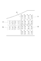
以下、上記複数の発光部材10の構成、および点灯制御手段20によるその制御方法について説明する。各発光部材10は、所定の発光色(例えば赤色)で発光する点状の発光源(例えばLED)である。図3に示すように、本実施形態では、計24個の発光部材10が搭載されている。発光部材10は、所定の態様で並べられて配置されている。発光部材10が配置された箇所には、並べられた発光部材10を区画するように「枠」が記載されている。本実施形態では、8個の発光部材10が内側に位置するように記載された枠が二つ(以下、当該枠に囲まれる領域を第一領域31および第二領域32と称する)、4個の発光部材10が内側に位置するように記載された枠が二つ(以下、当該枠に囲まれる領域を第三領域33および第四領域34と称する)設けられている。このように、本実施形態では、各領域に属する発光部材10がひとかたまりになるように並べられて配置されている。   Hereinafter, the configuration of the plurality of light emitting members 10 and the control method by the lighting control means 20 will be described. Each light emitting member 10 is a dot-like light source (for example, LED) that emits light in a predetermined light color (for example, red). As shown in FIG. 3, in the present embodiment, a total of 24 light emitting members 10 are mounted. The light emitting members 10 are arranged in a predetermined manner. In the place where the light emitting member 10 is disposed, a “frame” is described so as to partition the light emitting members 10 arranged. In the present embodiment, two frames are described so that the eight light emitting members 10 are positioned inside (hereinafter, the regions surrounded by the frames are referred to as the first region 31 and the second region 32), and four frames. There are provided two frames (hereinafter, regions surrounded by the frame are referred to as a third region 33 and a fourth region 34) so that the light emitting member 10 is positioned inside. As described above, in the present embodiment, the light emitting members 10 belonging to each region are arranged side by side so as to form a group.

第一領域31に位置する複数の発光部材10は、これらの発光部材10による点灯パターンの組み合わせによって、上記第一始動入賞口931に遊技球が入賞したことを契機として実行された当否判定結果の内容(大当たりの当否や、大当たりの種類(大当たり遊技終了後に時間短縮遊技状態に突入するか否か))を報知する(第一特別図柄表示)。第二領域32に位置する複数の発光部材10は、これらの発光部材10による点灯パターンの組み合わせによって、上記第二始動入賞口932に遊技球が入賞したことを契機として実行された当否判定結果の内容(大当たり、小当たりの当否や、大当たり、小当たりの種類(大当たり遊技終了後に時間短縮遊技状態に突入するか否か))を報知する(第二特別図柄表示)。第三領域33に位置する複数の発光部材10は、これらの発光部材10による点灯パターンの組み合わせによって、上記第一始動入賞口931に遊技球が入賞したことを契機として実行された当否判定結果が保留されている数(保留数)を報知する(第一特別図柄保留数表示)。第四領域34に位置する複数の発光部材10は、これらの発光部材10による点灯パターンの組み合わせによって、上記第二始動入賞口932に遊技球が入賞したことを契機として実行された当否判定結果が保留されている数(保留数)を報知する(第二特別図柄保留数表示)。   The plurality of light-emitting members 10 located in the first region 31 are determined by the combination of lighting patterns by the light-emitting members 10 as a result of the success / failure determination result that is executed when a game ball wins the first start winning opening 931. The contents (whether or not the jackpot is won and the type of jackpot (whether or not to enter the time-saving gaming state after the jackpot game is finished)) are notified (first special symbol display). The plurality of light emitting members 10 located in the second region 32 are determined by the combination of the lighting patterns by these light emitting members 10 as a result of the determination of success / failure that is executed when a game ball is won in the second start winning opening 932. The contents (whether or not the big hit, the big hit, the type of the big hit and the small hit (whether or not to enter the time-saving game state after the big hit game ends) are notified (second special symbol display). The plurality of light-emitting members 10 located in the third region 33 have a result of determination of success / failure that is executed when a game ball is won in the first start winning opening 931 by a combination of lighting patterns by the light-emitting members 10. The number of held (the number of held) is notified (first special symbol hold number display). The plurality of light-emitting members 10 located in the fourth region 34 have a result of the determination of success / failure that is executed when a game ball is won in the second start winning opening 932 by a combination of lighting patterns by the light-emitting members 10. The number of held items (the number of held items) is notified (second special symbol hold number display).

第一始動入賞口931に遊技球が入賞したことを契機とする当否判定結果の内容を報知する段(タイミング)になったときには、第一領域31に位置する複数の発光部材10のうちの少なくともいずれか一つを点灯させる点灯パターンを表示することにより、その当否判定が大当たりであったか否か、大当たりである場合にはその内容が示される。つまり、大当たり遊技終了後に時間短縮状態に突入するものであるかどうかが示される。同様に、第二始動入賞口932に遊技球が入賞したことを契機とする当否判定結果の内容を報知する段(タイミング)になったときには、第二領域32に位置する複数の発光部材10のうちの少なくともいずれか一つを点灯させる点灯パターンを表示することにより、その当否判定が大当たりであったか小当たりであったか、およびこれらの当たりの内容が示される。つまり、大当たりであった場合には、大当たり遊技終了後に時間短縮状態に突入するものであるかどうかが示され、小当たりであった場合には、Vアタッカー99が開放することによりV入賞口991に遊技球が入賞したときに、時間短縮遊技が継続する大当たりとなるものであるかどうかが示される。   When the stage (timing) for notifying the contents of the result of the determination of success / failure triggered by the winning of the game ball at the first start winning opening 931 is at least one of the plurality of light emitting members 10 located in the first region 31. By displaying a lighting pattern for lighting any one of them, whether or not the determination of success / failure is a big hit is made, and if it is a big hit, the contents are shown. That is, it is shown whether or not the time saving state is entered after the jackpot game ends. Similarly, when the time (timing) for notifying the content of the result of the determination of success / failure triggered by the winning of the game ball at the second start winning opening 932 is reached, the plurality of light emitting members 10 located in the second region 32 By displaying a lighting pattern in which at least one of them is lit, it is indicated whether the determination is a big hit or a small hit and the contents of these hits. In other words, if it is a big hit, it is shown whether or not the time reduction state will be entered after the jackpot game ends, and if it is a small hit, the V attacker 99 will be released by opening the V attacker 991. When the game ball wins, it is shown whether or not the time-saving game is a big hit that continues.

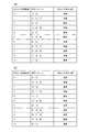
本実施形態における具体的な点灯パターンは図4および図5に示す通りである。大当たり遊技終了後に時間短縮遊技に突入するか否かは、大当たりとなったときに(第一始動入賞口931または第二始動入賞口932に遊技球が入賞したとき)に取得される大当たり図柄乱数によって決定される。本実施形態では、0〜10の乱数を含む乱数源が大当たり図柄乱数源として設定されており、当該乱数源から取得された大当たり図柄乱数が0、1、3、5、7、9であった場合には、大当たり遊技終了後に時間短縮遊技に突入する大当たりとなる。それ以外の大当たり図柄乱数、すなわち2、4、6、8、10であった場合には、大当たり遊技終了後に時間短縮遊技に突入せず、通常の遊技状態となる大当たりとなる。大当たり時の点灯パターンは、この取得された大当たり図柄乱数によって決まる。第一始動入賞口931に遊技球が入賞したことを契機とする大当たりの場合は、第一領域31に位置する発光部材10による点灯パターン(図4(a)参照)が示され、第二始動入賞口932に遊技球が入賞したことを契機とする大当たりの場合(小当たりを経た大当たりを除く)は、第二領域32に位置する発光部材10による点灯パターン(図4(b)参照)が示される。図4に示されるように、第一始動入賞口931に遊技球が入賞したことによって大当たりに当選した場合には第一領域31に位置する発光部材10の少なくとも一つを点灯させる点灯パターンが表示され、第二始動入賞口932に遊技球が入賞したことによって大当たりに当選した場合には第二領域32に位置する発光部材10の少なくとも一つを点灯させる点灯パターンが表示される。   Specific lighting patterns in the present embodiment are as shown in FIGS. Whether or not to enter the time-saving game after the jackpot game ends is determined by whether or not the jackpot symbol random number that is acquired when the jackpot is won (when a game ball wins at the first start winning port 931 or the second start winning port 932) Determined by. In this embodiment, a random number source including random numbers from 0 to 10 is set as a jackpot symbol random number source, and the jackpot symbol random number obtained from the random number source is 0, 1, 3, 5, 7, 9 In this case, after the jackpot game is over, it becomes a jackpot that enters a time-saving game. If the other jackpot symbol random number, that is, 2, 4, 6, 8, or 10, is not a rush game after the jackpot game ends, it becomes a jackpot to enter the normal gaming state. The lighting pattern at the time of jackpot is determined by the acquired jackpot symbol random number. In the case of a jackpot triggered by the winning of a game ball in the first start winning opening 931, a lighting pattern (see FIG. 4A) by the light emitting member 10 located in the first region 31 is shown, and the second start In the case of a jackpot triggered by the winning of a game ball in the winning opening 932 (excluding a jackpot that has passed a jackpot), the lighting pattern by the light emitting member 10 located in the second region 32 (see FIG. 4B). Indicated. As shown in FIG. 4, a lighting pattern for lighting at least one of the light emitting members 10 located in the first region 31 is displayed when a winning game is won by winning a game ball in the first start winning opening 931. When a big win is won by winning a game ball in the second start winning opening 932, a lighting pattern for lighting at least one of the light emitting members 10 located in the second area 32 is displayed.

一方、小当たりとなった場合、その小当たりによってVアタッカー99が開放することによりV入賞口991に遊技球が入賞した場合、時間短縮遊技が継続する大当たりとなるか否かは、小当たりとなったときに(第二始動入賞口932に遊技球が入賞したとき)に取得される小当たり図柄乱数によって決定される。本実施形態では、0〜10の乱数を含む乱数源が小当たり図柄乱数源として設定されており、当該乱数源から取得された小当たり図柄乱数が0、1、3、5、7、9であった場合には、当該小当たりを経て大当たりとなったときに当該大当たり遊技終了後に時間短縮遊技に突入する大当たりとなる。それ以外の小当たり図柄乱数、すなわち2、4、6、8、10であった場合には、当該小当たりを経て大当たりとなったときに当該大当たり遊技終了後に時間短縮遊技に突入せず、通常の遊技状態となる大当たりとなる。小当たり時の点灯パターンは、この取得された小当たり図柄乱数によって決まる。図5に示すように、第二領域32に位置する発光部材10の少なくとも一つを点灯させる点灯パターンが表示される。   On the other hand, when a small hit is made, if a game ball is won in the V winning opening 991 due to the V attacker 99 being released by the small hit, whether or not the time-saving game continues is a big hit. It is determined by the small hitting design random number acquired when the game ball wins at the second start winning opening 932. In the present embodiment, a random number source including random numbers from 0 to 10 is set as a small hitting design random number source, and the small hitting design random numbers acquired from the random number source are 0, 1, 3, 5, 7, 9 If there is a big hit after the small hit, it becomes a big hit that enters the time-saving game after the big hit game ends. If it is a small bonus symbol random number, that is, 2, 4, 6, 8, 10, it will not enter the time-reduced game after the jackpot game ends when the jackpot is reached after the bonus hit, It will be a big hit that will be in the gaming state. The lighting pattern at the time of the small hit is determined by the acquired small hit symbol random number. As shown in FIG. 5, a lighting pattern for lighting at least one of the light emitting members 10 located in the second region 32 is displayed.

このように、大当たりまたは小当たりとなったときには、第一領域31または第二領域32に位置する発光部材10による点灯パターンが発現される。当該点灯パターンには単純な法則性はないため、点灯パターンを一瞥しただけでは、遊技者は当否判定結果や当たりの内容は判断することができない。なお、当否判定結果は、表示装置92等において、遊技者がはっきりと認識できるようにしたり、暗示されるようにしたりしてもよい。   As described above, when the big hit or the small hit is obtained, a lighting pattern by the light emitting member 10 located in the first region 31 or the second region 32 is expressed. Since the lighting pattern does not have a simple rule, the player cannot determine the determination result or the winning content simply by glancing at the lighting pattern. Note that the determination result may be clearly recognized by the player or implied on the display device 92 or the like.

第一始動入賞口931に遊技球が入賞したことを契機とする当否判定結果で保留されているものがある場合には、第三領域33に位置する複数の発光部材10のうちの少なくともいずれか一つを点灯させる点灯パターンを表示することにより、その保留数を示す。同様に、第二始動入賞口932に遊技球が入賞したことを契機とする当否判定結果で保留されているものがある場合には、第四領域34に位置する複数の発光部材10のうちの少なくともいずれか一つを点灯させる点灯パターンを表示することにより、その保留数を示す。本実施形態では、それぞれの当否判定結果を最大四つまで保留することが可能であり、保留数が一つの場合は各領域における最も左側の発光部材10のみを点灯し、二つの場合は各領域における最も左側の発光部材10、およびその右側に隣接する発光部材10を点灯し、三つの場合には各領域における最も左側の発光部材10、その右側に隣接する発光部材10、およびさらにその右側に隣接する発光部材10を点灯し、四つの場合には各領域における全ての発光部材10を点灯させる。なお、本実施形態では、第一始動入賞口931への入賞を契機とする保留および第二始動入賞口932への入賞を契機とする保留の両方が存在する場合、第二始動入賞口932への入賞を契機とする保留を優先して消化(当否判定結果を報知)する(いわゆる電チュー優先消化である)。   In the case where there is an on-hold determination result triggered by the winning of a game ball at the first start winning opening 931, at least one of the plurality of light emitting members 10 located in the third region 33 By displaying a lighting pattern for lighting one, the number of holdings is indicated. Similarly, in the case where there is an on-hold determination result triggered by the winning of a game ball in the second start winning opening 932, among the plurality of light emitting members 10 located in the fourth region 34 The number of reserves is indicated by displaying a lighting pattern that lights at least one of them. In the present embodiment, it is possible to hold up to four determination results for each success / failure. When the number of holds is one, only the leftmost light emitting member 10 in each region is lit, and in the case of two each region. The leftmost light emitting member 10 and the right side light emitting member 10 on the right side thereof are turned on. In the three cases, the leftmost light emitting member 10 in each region, the right side light emitting member 10 on the right side, and further on the right side The adjacent light emitting members 10 are turned on, and in the case of four, all the light emitting members 10 in each region are turned on. In the present embodiment, when there are both a hold that is triggered by a winning at the first start winning opening 931 and a hold that is triggered by a winning at the second start winning prize 932, the second start winning opening 932 is entered. Priority is given to a hold that is triggered by the winning of a prize (notifying the result of the determination of success / failure) (this is so-called electric chew priority digestion).

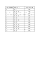
このように当否判定結果の内容および保留数を表示する複数の発光部材10は、複数の発光部材群に区分される。当該発光部材群の区分けは、上記領域(第一領域31〜第四領域34)による区分けとは異なる。本実施形態では、6個の発光部材10を含む発光部材群二つ(以下、第一発光部材群41、第二発光部材群42と称する)と、5個の発光部材10を含む発光部材群(以下、第三発光部材群43と称する)一つと、7個の発光部材10を含む発光部材群(以下、第四発光部材群44と称する)一つに区分されている。   As described above, the plurality of light emitting members 10 that display the contents of the determination result and the number of holds are divided into a plurality of light emitting member groups. The division of the light emitting member group is different from the division by the above regions (first region 31 to fourth region 34). In the present embodiment, two light emitting member groups including six light emitting members 10 (hereinafter referred to as a first light emitting member group 41 and a second light emitting member group 42) and a light emitting member group including five light emitting members 10. It is divided into one (hereinafter referred to as a third light emitting member group 43) and one light emitting member group (hereinafter referred to as a fourth light emitting member group 44) including seven light emitting members 10.

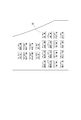
ある発光部材群に属する複数の発光部材10は、複数のコモン線のうちのいずれかに電気的に接続されている。本実施形態では、コモン線A〜コモン線Dのうちのいずれかに接続されている。複数のコモン線のうちのあるコモン線に接続された複数の発光部材10は、同じ発光部材群に属する。図6に示すように、コモン線Aに接続された複数の発光部材10は第一発光部材群41に属し、コモン線Bに接続された複数の発光部材10は第二発光部材群42に属し、コモン線Cに接続された複数の発光部材10は第三発光部材群43に属し、コモン線Dに接続された複数の発光部材10は第四発光部材群44に属する。   The plurality of light emitting members 10 belonging to a certain light emitting member group are electrically connected to any one of the plurality of common lines. In this embodiment, it is connected to any one of the common lines A to D. The plurality of light emitting members 10 connected to a common line among the plurality of common lines belong to the same light emitting member group. As shown in FIG. 6, the plurality of light emitting members 10 connected to the common line A belong to the first light emitting member group 41, and the plurality of light emitting members 10 connected to the common line B belong to the second light emitting member group 42. The plurality of light emitting members 10 connected to the common line C belong to the third light emitting member group 43, and the plurality of light emitting members 10 connected to the common line D belong to the fourth light emitting member group 44.

各発光部材10は、複数のセグメント線のうちのいずれかに電気的に接続されている。本実施形態では、セグメント線A〜セグメント線Hのうちのいずれかに接続されている。図6に示すように、同じ発光部材群に属する発光部材10は、各々が別のセグメント線に接続されている。つまり、同じ発光部材群に属する二以上の発光部材10が、同じセグメント線に接続されることはない。ただし、同じコモン・セグメント間に配置する発光部材10は一つでも複数でもよい。   Each light emitting member 10 is electrically connected to one of a plurality of segment lines. In this embodiment, it is connected to any one of the segment lines A to H. As shown in FIG. 6, the light emitting members 10 belonging to the same light emitting member group are each connected to a different segment line. That is, two or more light emitting members 10 belonging to the same light emitting member group are not connected to the same segment line. However, one or more light emitting members 10 may be disposed between the same common segments.

このように電気的接続がなされた複数の発光部材10は、所定の点灯パターンを発現するに際し、主制御基板971(点灯制御手段)によってダイナミック点灯方式により制御される。ダイナミック点灯方式は、あるコモン線(第一コモン線)に接続されている発光部材群に含まれる複数の発光部材10のうち、点灯させるべきものをセグメント線のON/OFFを制御することにより同時に点灯させ、それを消灯させた後、別のコモン線(第二コモン線)に接続されている発光部材群に含まれる複数の発光部材10のうち、点灯させるべきものをセグメント線のON/OFFを制御することにより同時に点灯させる、というように、全ての発光部材10を同時に点灯させるのではなく、発光部材群単位(コモン線単位)で発光部材10の点灯(消灯)を制御し、それを高速で切り替えることにより、人間の視覚的には全ての発光部材10が同時に点灯しているかのように認識されるものである。このような制御方式を用いることにより、配線および制御構造の簡易化が実現できる。本実施形態では、第一発光部材群41(コモン線A)、第二発光部材群42(コモン線B)、第三発光部材群43(コモン線C)、第四発光部材群44(コモン線D)、第一発光部材群41(コモン線A)・・・というように、点灯を制御する発光部材群を切り替えていく。なお、上述したあるコモン線(第一コモン線)は、コモン線A〜コモン線Dの何れに相当するものであってもよい。同様に、上述した別のコモン線(第二コモン線)は、第一コモン線とは別のコモン線A〜コモン線Dのうちの何れかのコモン線に相当するものである。   The plurality of light emitting members 10 thus electrically connected are controlled by the dynamic lighting method by the main control board 971 (lighting control means) when a predetermined lighting pattern is developed. In the dynamic lighting method, among the plurality of light emitting members 10 included in the light emitting member group connected to a certain common line (first common line), one to be turned on is controlled simultaneously by controlling ON / OFF of the segment line. After turning it on and turning it off, turn on / off the segment line of the plurality of light emitting members 10 included in the light emitting member group connected to another common line (second common line). Instead of lighting all the light emitting members 10 at the same time, such as turning on the light by controlling the lighting, the lighting (lighting off) of the light emitting members 10 is controlled in units of light emitting member groups (common line units). By switching at high speed, it is recognized by human eyes as if all the light emitting members 10 are lit simultaneously. By using such a control method, the wiring and the control structure can be simplified. In the present embodiment, the first light emitting member group 41 (common line A), the second light emitting member group 42 (common line B), the third light emitting member group 43 (common line C), and the fourth light emitting member group 44 (common line). D), the first light emitting member group 41 (common line A),... The certain common line (first common line) described above may correspond to any of the common line A to the common line D. Similarly, another common line (second common line) described above corresponds to any one of the common lines A to D different from the first common line.

このように、本実施形態では、上述した特別図柄表示や保留数等の遊技に関する遊技情報を報知するに際し、あるコモン線(第一コモン線)に接続された発光部材群に含まれる発光部材10の少なくとも一部と、それとは異なるコモン線(第二コモン線)に接続された発光部材群に含まれる発光部材10の少なくとも一部と、を含む複数の発光部材10の点灯パターンによって報知される。例えば、第二始動入賞口932に遊技球が入賞したことを契機とする当否判定結果の内容(第二特別図柄表示)は、第二領域32内に位置する複数の発光部材10による点灯パターンによって示されることになるが、当該第二領域32に位置する複数の発光部材10には、全ての発光部材群に属する発光部材10が存在する(本実施形態では第一発光部材群41に属する1個の発光部材、第二発光部材群42に属する4個の発光部材、第三発光部材群43に属する1個の発光部材、第四発光部材群44に属する2個の発光部材群が含まれる)ことになる。そのため、第二特別図柄表示は、視覚的には、同時に点灯しているかのように見えるが、実際には点灯すべき発光部材10が、接続されたコモン線に応じて経時的に切り替わっているということになる。それゆえ、カメラなどの撮像手段によって静止画を撮像したとしても、当該静止画は一の発光部材群に属する(一のコモン線に接続された)一または複数の発光部材10を点灯(一部を点灯させたというものだけではなく、全てを点灯させたり、全てを消灯したままにしたりする場合もある)させた瞬間を捉えたものに過ぎず、第二特別図柄表示そのものを捉えることはできないことになる。   As described above, in the present embodiment, when notifying the game information related to the game such as the special symbol display and the number of holds, the light emitting member 10 included in the light emitting member group connected to a certain common line (first common line). And a lighting pattern of a plurality of light emitting members 10 including at least a part of the light emitting members 10 included in the light emitting member group connected to a different common line (second common line). . For example, the content of the determination result (second special symbol display) triggered by the winning of the game ball in the second start winning opening 932 is based on the lighting pattern by the plurality of light emitting members 10 located in the second region 32. As shown, the light emitting members 10 belonging to all the light emitting member groups are present in the plurality of light emitting members 10 located in the second region 32 (in this embodiment, 1 belonging to the first light emitting member group 41). 1 light emitting member, four light emitting members belonging to the second light emitting member group 42, one light emitting member belonging to the third light emitting member group 43, and two light emitting member groups belonging to the fourth light emitting member group 44 are included. ) Therefore, the second special symbol display visually looks as if it is lit at the same time, but in reality, the light emitting member 10 to be lit is switched over time according to the connected common line. It turns out that. Therefore, even when a still image is captured by an imaging means such as a camera, the still image lights one or more light emitting members 10 belonging to one light emitting member group (connected to one common line) (partly) It is not only the one that lights up, but it may only capture the moment when everything is turned on or leave all turned off), it cannot capture the second special symbol display itself It will be.

なお、第二領域32に位置する複数の発光部材10には、全ての発光部材群に属する発光部材10が存在するが、本実施形態における第一領域31や第二領域32のように、必ずしもすべての発光部材群に属する発光部材10が存在しなくてもよい。すなわち、少なくとも二つの発光部材群に属する発光部材10が存在するように(異なる発光部材群に属する発光部材10が存在するように)振り分けられていればよい。   In addition, although the light emitting member 10 which belongs to all the light emitting member groups exists in the some light emitting member 10 located in the 2nd area | region 32, like the 1st area | region 31 and the 2nd area | region 32 in this embodiment, it does not necessarily exist. The light emitting members 10 belonging to all the light emitting member groups may not exist. That is, it is only necessary that the light emitting members 10 belonging to at least two light emitting member groups exist (so that the light emitting members 10 belonging to different light emitting member groups exist).

以上説明した本実施形態にかかる遊技機1によれば、次のような作用効果が奏される。   According to the gaming machine 1 according to the present embodiment described above, the following operational effects are exhibited.

本実施形態にかかる遊技機1では、遊技に関するある(一つの)遊技情報が、あるコモン線(第一コモン線)に接続された発光部材10と、それとは異なるコモン線(第二コモン線)に接続された発光部材10を含む複数の発光部材10の点灯パターンによって報知されることになる。つまり、当該ある(一つの)遊技情報を報知する点灯パターンを発現するための複数の発光部材10は、全て同じコモン線に配置されているのではなく、複数のコモン線に配置されているため、全て同時に点灯するものではないから、点灯した瞬間を撮像すること等による点灯パターンの解読を困難にすることが可能である。   In the gaming machine 1 according to the present embodiment, a certain (one) piece of game information related to the game is a light emitting member 10 connected to a certain common line (first common line), and a common line (second common line) different from the light emitting member 10. It is notified by the lighting pattern of the several light emitting member 10 containing the light emitting member 10 connected to. That is, the plurality of light emitting members 10 for expressing the lighting pattern for notifying the certain (one) game information are not arranged on the same common line, but are arranged on a plurality of common lines. Since they are not all turned on at the same time, it is possible to make it difficult to decipher the lighting pattern by taking an image of the moment of lighting.

特に、本実施形態にかかる遊技機1は、第一始動入賞口931または第二始動入賞口932に遊技球が入賞したときの抽選に当選することよって大当たりを獲得することができるだけでなく、小当たりを経てV入賞口991に遊技球が入賞することにより大当たりを獲得することができるものである。V入賞口991に遊技球が入賞することによる大当たりの場合、当該大当たり遊技終了後に時間短縮遊技状態に突入するか否かは、小当たり時に取得される小当たり図柄乱数によって決まる。そして、取得された小当たり図柄乱数に基づき、第二領域32に位置する複数の発光部材10による点灯パターンが表示され、その後、Vアタッカー99(V入賞口991)が開放する。したがって、点灯パターンが解読され、時間短縮遊技状態が継続する大当たりとなる小当たりであるか否かが判別されてしまうと、時間短縮遊技状態が継続する小当たりが発生した場合のみVアタッカー99を狙って遊技球を発射させる、という行為が発生しうる。本実施形態では、上述したように点灯パターンの解読が困難となっているため、いわゆる一種二種混合機の遊技機におけるこのような行為を困難にすることが可能である。   In particular, the gaming machine 1 according to the present embodiment can not only win a jackpot by winning a lottery when a game ball wins at the first start winning opening 931 or the second starting winning opening 932, A winning game can be won by winning a game ball in the V winning opening 991 after winning. In the case of a big hit by winning a game ball in the V winning opening 991, whether or not to enter the time-saving game state after the end of the big win game is determined by the small hit symbol random number acquired at the time of the small win. And the lighting pattern by the several light emission member 10 located in the 2nd area | region 32 is displayed based on the acquired small hit design random number, and V attacker 99 (V winning opening 991) is open | released after that. Therefore, if the lighting pattern is decoded and it is determined whether or not the small hit that becomes the big hit in which the time-reduced gaming state continues, the V attacker 99 is used only when the small hit in which the reduced time gaming state continues. An act of aiming and firing a game ball may occur. In this embodiment, since it is difficult to decipher the lighting pattern as described above, it is possible to make such an action difficult in a so-called one-type / two-type gaming machine.

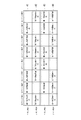
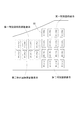
以下、変形例にかかる遊技機について上記実施形態にかかる遊技機1と異なる点を中心に説明する。上記実施形態にかかる遊技機1では、図3に示すように報知する遊技情報毎に複数の発光部材10がひとかたまりに並べられていること(報知する遊技情報毎に第一領域31〜第四領域34に区分けされて並べられていることを)を説明したが、変形例にかかる遊技機は、報知する遊技情報毎に複数の発光部材10がひとかたまりに並べられるのではなく、秩序なく混在するように並べられたものである。   Hereinafter, the gaming machine according to the modified example will be described focusing on differences from the gaming machine 1 according to the embodiment. In the gaming machine 1 according to the above embodiment, a plurality of light-emitting members 10 are arranged in a group for each game information to be notified as shown in FIG. 3 (first area 31 to fourth area for each game information to be notified). However, in the gaming machine according to the modified example, a plurality of light emitting members 10 are not arranged in a lump for each game information to be notified, but are mixed in an orderly manner. Are arranged.

このような遊技機における複数の発光部材10の配置例としては、図7に示すような例が挙げられる。このようにすれば、ダイナミック点灯方式を採用することによる作用に、ある遊技情報を報知するための発光部材10がどの位置に位置しているかが判別しにくくなるという作用が加わるため、点灯パターンの解読をさらに困難にすることが可能である。   An example of the arrangement of the plurality of light emitting members 10 in such a gaming machine is as shown in FIG. In this way, the effect of adopting the dynamic lighting method is added to the effect of making it difficult to determine where the light emitting member 10 for notifying certain game information is located. Decryption can be made more difficult.

以上、本発明の実施の形態について詳細に説明したが、本発明は上記実施の形態に何ら限定されるものではなく、本発明の要旨を逸脱しない範囲で種々の改変が可能である。   Although the embodiments of the present invention have been described in detail above, the present invention is not limited to the above-described embodiments, and various modifications can be made without departing from the gist of the present invention.

上記実施形態にかかる遊技機1は、始動入賞口への遊技球の入賞を契機とする抽選に当選することによる大当たりだけでなく、小当たりを経てV入賞口991に遊技球が入賞することによる大当たりが搭載されたいわゆる一種二種混合(遊技)機であることを説明したが、この種の遊技機以外にも適用可能である。ある入賞口への遊技球の入賞を契機とする抽選に当選することによって大当たりを獲得することができるいわゆる一種遊技機や、ある入賞口に遊技球が入賞することによって大当たりを獲得することができるいわゆる二種遊技機にも適用可能である。つまり、大当たりや小当たり等の当否判定結果の内容、保留数の表示といった遊技に関する遊技情報を、複数の発光部材の点灯パターンによって報知する遊技機に対し、本発明の技術的思想は適用可能である。また、大当たり図柄乱数や小当たり図柄乱数や図柄の数(点灯パターン)や保留の数等は適宜変更可能であり、大当たりの図柄乱数や小当たり図柄乱数や図柄の数(点灯パターン)が多いほど点灯パターンの意味を複雑化させることが可能となる。さらに、時間短縮遊技状態になる(時間短縮遊技状態が継続する)か否かの割合も適宜変更可能である。   The gaming machine 1 according to the above embodiment is based not only on winning a lottery with the winning of a game ball at the start winning opening, but also on winning the V winning opening 991 through a small win. Although it has been described that it is a so-called two-type mixed (game) machine equipped with jackpots, it can also be applied to other than this type of game machine. A so-called type of gaming machine that can win a jackpot by winning a lottery when a game ball wins a certain winning opening, or a winning jackpot when a game ball wins a certain winning opening It can also be applied to so-called two-type gaming machines. In other words, the technical idea of the present invention can be applied to a gaming machine that informs game information related to a game such as the contents of the result of determination of success / failure such as big wins or small wins, and display of the number of holdings by lighting patterns of a plurality of light emitting members. is there. In addition, the jackpot symbol random number, the jackpot symbol random number, the number of symbols (lighting pattern), the number of holdings, etc. can be changed as appropriate. The larger the jackpot symbol random number, the jackpot symbol random number, or the number of symbols (lighting pattern) The meaning of the lighting pattern can be complicated. Furthermore, the ratio of whether or not the time reduction gaming state is reached (the time reduction gaming state continues) can be changed as appropriate.

1 遊技機
10 発光部材
20 点灯制御手段
31 第一領域
32 第二領域
33 第三領域
34 第四領域
41 第一発光部材群
42 第二発光部材群
43 第三発光部材群
44 第四発光部材群
91 遊技領域
91L 左側遊技領域
92R 右側遊技領域
931 第一始動入賞口
932 第二始動入賞口
991 V入賞口
1 gaming machine 10 light emitting member 20 lighting control means 31 first region 32 second region 33 third region 34 fourth region 41 first light emitting member group 42 second light emitting member group 43 third light emitting member group 44 fourth light emitting member group 91 game area 91L left game area 92R right game area 931 first start winning port 932 second starting winning port 991 V winning port

Claims (1)

複数の発光部材と、
前記複数の発光部材が複数の発光部材群に区分されるとともに、各発光部材群に含まれる発光部材に電気的に接続されるコモン線を介して点灯パターンを制御する点灯制御手段と、
を備え、
前記コモン線として、前記複数の発光部材群のうちの一つである第一発光部材群に含まれる複数の発光部材に接続された第一コモン線と、前記複数の発光部材群のうちの一つである第二発光部材群に含まれる複数の発光部材に接続された第二コモン線と、が設けられ、
遊技に関する第一遊技情報が、前記第一発光部材群に含まれる発光部材の少なくとも一部と、前記第二発光部材群に含まれる発光部材の少なくとも一部と、を含む複数の発光部材の点灯パターンによって報知され、
前記第一遊技情報と異なる第二遊技情報が、前記第一発光部材群に含まれる発光部材の少なくとも一部と、前記第二発光部材群に含まれる発光部材の少なくとも一部と、を含む複数の発光部材の点灯パターンによって報知されることを特徴とする遊技機。
A plurality of light emitting members;
The plurality of light emitting members are divided into a plurality of light emitting member groups, and a lighting control means for controlling a lighting pattern through a common line electrically connected to the light emitting members included in each light emitting member group;
With
As the common line, a first common line connected to a plurality of light emitting members included in a first light emitting member group which is one of the plurality of light emitting member groups, and one of the plurality of light emitting member groups. A second common line connected to a plurality of light emitting members included in the second light emitting member group,
Lighting of a plurality of light emitting members, wherein the first game information relating to the game includes at least a part of the light emitting members included in the first light emitting member group and at least a part of the light emitting members included in the second light emitting member group Informed by the pattern,
A plurality of second game information different from the first game information includes at least a part of light emitting members included in the first light emitting member group and at least a part of light emitting members included in the second light emitting member group. A gaming machine that is notified by a lighting pattern of the light emitting member.
JP2015219605A 2015-11-09 2015-11-09 Game machine Active JP6263760B2 (en)

Priority Applications (1)

Application Number Priority Date Filing Date Title
JP2015219605A JP6263760B2 (en) 2015-11-09 2015-11-09 Game machine

Applications Claiming Priority (1)

Application Number Priority Date Filing Date Title
JP2015219605A JP6263760B2 (en) 2015-11-09 2015-11-09 Game machine

Related Parent Applications (1)

Application Number Title Priority Date Filing Date
JP2013152396A Division JP2015019997A (en) 2013-07-23 2013-07-23 Game machine

Publications (3)

Publication Number Publication Date
JP2016026831A JP2016026831A (en) 2016-02-18
JP2016026831A5 JP2016026831A5 (en) 2016-09-01
JP6263760B2 true JP6263760B2 (en) 2018-01-24

Family

ID=55352484

Family Applications (1)

Application Number Title Priority Date Filing Date
JP2015219605A Active JP6263760B2 (en) 2015-11-09 2015-11-09 Game machine

Country Status (1)

Country Link
JP (1) JP6263760B2 (en)

Families Citing this family (1)

* Cited by examiner, † Cited by third party
Publication number Priority date Publication date Assignee Title
JP6618224B2 (en) * 2019-01-23 2019-12-11 株式会社大一商会 Game machine

Family Cites Families (6)

* Cited by examiner, † Cited by third party
Publication number Priority date Publication date Assignee Title
JPH06312054A (en) * 1993-04-30 1994-11-08 Maruhon Kogyo Kk Pachinko game machine
JP2000189585A (en) * 1998-12-28 2000-07-11 Daiichi Shokai Co Ltd Display drive circuit for gaming machines
JP2003290510A (en) * 2002-03-29 2003-10-14 Daiichi Shokai Co Ltd Gaming machine
JP4139263B2 (en) * 2003-04-23 2008-08-27 株式会社サンセイアールアンドディ Game machine
JP2005312652A (en) * 2004-04-28 2005-11-10 Aruze Corp Game machine and simulation program
JP5386406B2 (en) * 2010-02-26 2014-01-15 株式会社サンセイアールアンドディ Game machine

Also Published As

Publication number Publication date
JP2016026831A (en) 2016-02-18

Similar Documents

Publication Publication Date Title
JP6160391B2 (en) Bullet ball machine
JP5590565B2 (en) Bullet ball machine
JP5105515B2 (en) Game machine
JP2020124336A (en) Game machine
JP2005087342A (en) Pinball machine
JP5685303B2 (en) Bullet ball machine
JP6263760B2 (en) Game machine
JP4544472B2 (en) Bullet ball machine
JP2015019997A (en) Game machine
JP5129033B2 (en) Game machine
JP2002233619A (en) Game machine
JP7083480B2 (en) Pachinko machine
JP4919224B2 (en) Bullet ball machine
JP7663217B2 (en) Gaming Machines
JP7270971B2 (en) pachinko machine
JP2010104726A (en) Pinball game machine
JP2022098264A (en) Game machine
JP2010069071A5 (en)
JP2021083674A (en) Game machine
JP2020010954A (en) Game machine
JP6800486B2 (en) Game machine
JP7191718B2 (en) game machine
JP6952979B2 (en) Pachinko machine
JP2002066008A (en) Game machine
JP5182971B2 (en) Bullet ball machine

Legal Events

Date Code Title Description
A521 Request for written amendment filed

Free format text: JAPANESE INTERMEDIATE CODE: A523

Effective date: 20151124

A521 Request for written amendment filed

Free format text: JAPANESE INTERMEDIATE CODE: A523

Effective date: 20160713

A621 Written request for application examination

Free format text: JAPANESE INTERMEDIATE CODE: A621

Effective date: 20160713

A977 Report on retrieval

Free format text: JAPANESE INTERMEDIATE CODE: A971007

Effective date: 20170626

A131 Notification of reasons for refusal

Free format text: JAPANESE INTERMEDIATE CODE: A131

Effective date: 20170704

A521 Request for written amendment filed

Free format text: JAPANESE INTERMEDIATE CODE: A523

Effective date: 20170829

TRDD Decision of grant or rejection written
A01 Written decision to grant a patent or to grant a registration (utility model)

Free format text: JAPANESE INTERMEDIATE CODE: A01

Effective date: 20171107

A61 First payment of annual fees (during grant procedure)

Free format text: JAPANESE INTERMEDIATE CODE: A61

Effective date: 20171124

R150 Certificate of patent or registration of utility model

Ref document number: 6263760

Country of ref document: JP

Free format text: JAPANESE INTERMEDIATE CODE: R150

R250 Receipt of annual fees

Free format text: JAPANESE INTERMEDIATE CODE: R250

R250 Receipt of annual fees

Free format text: JAPANESE INTERMEDIATE CODE: R250

R250 Receipt of annual fees

Free format text: JAPANESE INTERMEDIATE CODE: R250

R250 Receipt of annual fees

Free format text: JAPANESE INTERMEDIATE CODE: R250

R250 Receipt of annual fees

Free format text: JAPANESE INTERMEDIATE CODE: R250