JP6263719B2 - Piezoelectric vibrator, piezoelectric unit, piezoelectric oscillator and electronic device - Google Patents
Piezoelectric vibrator, piezoelectric unit, piezoelectric oscillator and electronic device Download PDFInfo
- Publication number
- JP6263719B2 JP6263719B2 JP2017079278A JP2017079278A JP6263719B2 JP 6263719 B2 JP6263719 B2 JP 6263719B2 JP 2017079278 A JP2017079278 A JP 2017079278A JP 2017079278 A JP2017079278 A JP 2017079278A JP 6263719 B2 JP6263719 B2 JP 6263719B2
- Authority
- JP
- Japan
- Prior art keywords
- tuning fork
- fork arm
- vibrating
- width
- length
- Prior art date
- Legal status (The legal status is an assumption and is not a legal conclusion. Google has not performed a legal analysis and makes no representation as to the accuracy of the status listed.)
- Active
Links
Images


Landscapes
- Piezo-Electric Or Mechanical Vibrators, Or Delay Or Filter Circuits (AREA)
- Oscillators With Electromechanical Resonators (AREA)
Description
本発明は音叉型の圧電振動子(音叉型圧電振動子)と、その音叉型圧電振動子とケースと蓋とを備えて構成される圧電ユニットと、その圧電ユニットを備える圧電発振回路を備えた圧電発振器とその圧電発振器を備えた電子機器とそれらの製造方法に関する。 The present invention includes a tuning fork type piezoelectric vibrator (tuning fork type piezoelectric vibrator), a piezoelectric unit including the tuning fork type piezoelectric vibrator, a case, and a lid, and a piezoelectric oscillation circuit including the piezoelectric unit. The present invention relates to a piezoelectric oscillator, an electronic apparatus including the piezoelectric oscillator, and a manufacturing method thereof.
一例として、特許文献1の段落0035には、屈曲モードで振動する音叉形状の屈曲水晶振動子145の平面図が示され、音叉腕(振動部)の先端部の腕幅を広くした形状を有することにより、音叉腕が質量効果を持つ。それ故、同じ周波数でもより腕の長さを短くできるので小型化ができ、実際には、腕幅を広くする音叉腕の長さは、音叉腕の自由端である先端部から腕の長さの約半分の位置まで、広く形成される。即ち、前記範囲内で任意の位置に幅が広く設けられる。ことが記載されている。すなわち、基部側から先端部の約半分の位置に第1幅Wfが、その第1幅より広い第2幅Wsが音叉腕の自由端である先端部から腕の長さの約半分の位置に形成されている。この形状では、基本波モード振動の発振周波数が、例えば約32.768kHzで、その周波数での等価直列抵抗Rmの増加を抑え、かつ、ある程度の小型化(例えば、全長が2mmの水晶ユニット)を図ることができるが、全長が2mmより小さいより小型化された水晶ユニットを実現するには、音叉形状の屈曲水晶振動子のWsf=Ws/Wfをかなり大きく、かつ、Wfをかなり小さくする必要がある。しかし、Wsf=Ws/Wfをかなり大きく、かつ、Wfをかなり小さくすると等価直列抵抗Rmが全長2mmの水晶ユニットの等価直列抵抗の2倍以上と極めて大きな等価直列抵抗となると共に、バラツキも大きくなり、等価直列抵抗Rmの増加を抑制した音叉腕のより短い超小型の音叉型屈曲水晶振動子を実現ことは極めて困難であった。
このようなことから、基本波モード振動での等価直列抵抗Rmの増加を抑制した音叉腕のより短い超小型の音叉型圧電振動子を実現するには、新形状で、かつ、新電極配置を備えた音叉型圧電振動子と、その音叉型圧電振動子と蓋とケースとを備えて構成される圧電ユニットと、その圧電ユニットと増幅器とコンデンサと抵抗とを備えて構成される圧電発振器と、その圧電発振器を備えた電子機器と、それらの製造方法が所望されていた。For this reason, in order to realize a shorter micro tuning fork type piezoelectric vibrator of the tuning fork arms which can suppress an increase in equivalent series resistance R m of the fundamental mode vibration is a new shape, and the new electrode arrangement A tuning fork type piezoelectric vibrator comprising: a piezoelectric unit comprising the tuning fork type piezoelectric vibrator, a lid and a case; a piezoelectric oscillator comprising the piezoelectric unit, an amplifier, a capacitor, and a resistor; There has been a demand for an electronic device including the piezoelectric oscillator and a method for manufacturing the electronic device.
本発明は、以下の方法で従来の課題を有利に解決した逆相の屈曲モードで振動する、超小型の音叉型圧電振動子と、その音叉型圧電振動子と蓋とケースとを備えて構成される圧電ユニットと、その圧電ユニットと増幅器とコンデンサと抵抗とを備えて構成される圧電発振器と、その圧電発振器を備えた電子機器と、それらの製造方法を提供することを目的とするものである。 The present invention comprises an ultra-compact tuning fork type piezoelectric vibrator that vibrates in a reverse-phase bending mode that advantageously solves the conventional problems by the following method, the tuning fork type piezoelectric vibrator, a lid, and a case. It is an object of the present invention to provide a piezoelectric unit, a piezoelectric oscillator including the piezoelectric unit, an amplifier, a capacitor, and a resistor, an electronic device including the piezoelectric oscillator, and a manufacturing method thereof. is there.
すなわち、本発明の圧電振動子の第1の態様は、基部部分と第1音叉腕と第2音叉腕とを備えて構成され、第1音叉腕と第2音叉腕の各音叉腕の上面と下面の各々に溝が形成され、各溝の面の上に電極が配置された圧電振動子で、第1音叉腕と第2音叉腕の各音叉腕は第1幅W1を少なくとも備えた第1振動部と、第1幅W1より大きい第2幅W2を少なくとも備えた第2振動部と、を少なくとも備え、第1振動部は第2振動部より基部部分の側にあって、第1振動部の側面は接続部分の側面を介して第2振動部の側面に接続され、前記接続部分の側面は第1音叉腕と第2音叉腕の各音叉腕の第1長さ部分より長い音叉腕の先端部分の側にあり、幅の比W12がW12=W2/W1で定義されるとき、W12は1.2〜2.7の範囲内にある圧電振動子である。
本発明の圧電振動子の第2の態様は、第1の態様において、第1音叉腕と第2音叉腕の各音叉腕が延在する方向における長さL 1 を有し、基部部分に接続された接続部分を備えた圧電振動子で、基部部分は第1基部部分と第2基部部分とを備え、第1基部部分と第2基部部分の間には少なくとも一個のカット部分が形成され、第1音叉腕と第2音叉腕の各音叉腕は第1基部部分に接続され、接続部分は第2基部部分の幅方向に延在するように第2基部部分に接続され、接続部分の長さL1は0.01mm<L1<0.075mmの関係を備えている圧電振動子である。
本発明の圧電振動子の第3の態様は、第1の態様または第2の態様において、第1振動部の側面の一端部は接続部分の側面の一端部で接続され、この接続部分をS1で示し、第2振動部の側面の一端部は接続部分の側面の他端部で接続され、この接続部分をS2で示すとき、S2の位置は音叉腕の第1長さ部分より長い音叉腕の先端部分の側にあり、第2振動部の側面の音叉先端方向と接続部分の側面の延長方向との成す角度をθで定義するとき、θは90°より小さい圧電振動子である。
本発明の圧電振動子の第4の態様は、第1の態様から第3の態様のいずれか一つの態様において、第1音叉腕と第2音叉腕の各音叉腕は第2幅W2より大きい第3幅W3を少なくとも備えた第3振動部を少なくとも備え、第2振動部は第1振動部と第3振動部の間に形成され、第2振動部の長さがL2で、第3振動部の長さがL3で与えられるとき、L2<L3の関係を備え、幅の比W23がW23=W3/W2で定義されるとき、W23は1.2〜2.7の範囲内にある圧電振動子である。
本発明の圧電振動子の第5の態様は、第1の態様から第4の態様のいずれか一つの態様において、第1音叉腕と第2音叉腕の各音叉腕の3L/5の位置と3L/4の位置をそれぞれ第2長さ部分と第4長さ部分で定義されるとき、各音叉腕の第2振動部は第2長さ部分と第4長さ部分の間にある圧電振動子である。That is, the first aspect of the piezoelectric vibrator of the present invention includes a base portion, a first tuning fork arm, and a second tuning fork arm, and includes an upper surface of each tuning fork arm of the first tuning fork arm and the second tuning fork arm. grooves are formed on the lower surface of each piezoelectric vibrator having electrodes disposed on a surface of each groove, the respective tuning fork arms of the first fork arm and the second tuning fork arms are provided with at least a first width W 1 a first vibrating part and a second vibrating section having at least a first width W 1 greater than the second width W 2, comprising at least a first vibrating portion in the side of the base portion than the second vibrating portion, the The side surface of the first vibration part is connected to the side surface of the second vibration part via the side surface of the connection part, and the side surface of the connection part is longer than the first length part of each tuning fork arm of the first tuning fork arm and the second tuning fork arm. When the width ratio W 12 is defined by W 12 = W 2 / W 1 on the tip end side of the tuning fork arm, W 12 is in the range of 1.2 to 2.7. This is a piezoelectric vibrator.
A second aspect of the piezoelectric oscillator of the present invention, in a first aspect, has a length L 1 in the direction in which the tuning fork arms of the first fork arm and the second tuning fork arms extend, connected to the base portion In the piezoelectric vibrator having the connected portion, the base portion includes a first base portion and a second base portion, and at least one cut portion is formed between the first base portion and the second base portion, Each tuning fork arm of the first tuning fork arm and the second tuning fork arm is connected to the first base portion, and the connection portion is connected to the second base portion so as to extend in the width direction of the second base portion. is L 1 is a piezoelectric vibrator has a relation of 0.01
According to a third aspect of the piezoelectric vibrator of the present invention, in the first aspect or the second aspect, one end portion of the side surface of the first vibrating portion is connected to one end portion of the side surface of the connection portion. 1 , one end portion of the side surface of the second vibrating portion is connected to the other end portion of the side surface of the connection portion, and when this connection portion is indicated by S < b > 2 , the position of S < b > 2 is longer than the first length portion of the tuning fork arm. When the angle formed by the tuning fork tip direction on the side surface of the second vibrating part and the extending direction of the side surface of the connection part is defined as θ, θ is a piezoelectric vibrator smaller than 90 °. .
According to a fourth aspect of the piezoelectric vibrator of the present invention, in any one of the first to third aspects, each tuning fork arm of the first tuning fork arm and the second tuning fork arm has a second width W 2 . comprising at least a third vibration section having at least a large third width W 3, the second vibrating part is formed between the third vibrating part and the first vibrating portion, the length of the second vibrating portion in L 2, when the length of the third vibrating part is given by L 3, with the relationship of
According to a fifth aspect of the piezoelectric vibrator of the present invention, in any one of the first to fourth aspects, a position of 3L / 5 of each tuning fork arm of the first tuning fork arm and the second tuning fork arm When the position of 3L / 4 is defined by the second length portion and the fourth length portion, respectively, the second vibration portion of each tuning fork arm is between the second length portion and the fourth length portion. It is a child.
本発明の圧電ユニットの第1の態様は、第1の態様から第5の態様のいずれか一つの態様の圧電振動子を備えて構成される圧電ユニットである。
本発明の圧電ユニットの第2の態様は、第1の態様から第5の態様のいずれか一つの態様の圧電振動子とケースと蓋とを備えた圧電ユニットで、圧電振動子はケース内に収納されている圧電ユニットである。
本発明の圧電発振器の第1の態様は、第1の態様から第5の態様のいずれか一つの態様の圧電振動子を、あるいは第1の態様または第2の態様の圧電ユニットを備えて構成される圧電発振回路を備えている圧電発振器である。
本発明の電子機器の第1の態様は、第1の態様から第5の態様のいずれか一つの態様の圧電振動子と、あるいは第1の態様または第2の態様の圧電ユニットと、あるいは第1の態様の圧電発振器と、表示部とを備えている電子機器である。A first aspect of the piezoelectric unit of the present invention is a piezoelectric unit configured to include the piezoelectric vibrator according to any one of the first to fifth aspects.
According to a second aspect of the piezoelectric unit of the present invention, there is provided a piezoelectric unit including the piezoelectric vibrator according to any one of the first to fifth aspects, a case, and a lid. The piezoelectric unit is housed.
According to a first aspect of the piezoelectric oscillator of the present invention, the piezoelectric vibrator according to any one of the first to fifth aspects or the piezoelectric unit according to the first or second aspect is provided. The piezoelectric oscillator includes the piezoelectric oscillation circuit.
According to a first aspect of the electronic device of the present invention, the piezoelectric vibrator according to any one of the first to fifth aspects, the piezoelectric unit according to the first aspect or the second aspect, or the first aspect. It is an electronic device provided with the piezoelectric oscillator of 1 aspect and a display part.
この構成により、等価直列抵抗Rmの増加を抑えた超小型の音叉型圧電振動子が実現できる。その結果、その音叉型圧電振動子を備えた水晶ユニットの長さ寸法が1.8mmより小さい超小型の水晶ユニットが高品質で実現できる。この寸法は本発明によって初めてもたらされるものでありその作用効果は極めて大きなものである。This configuration can be realized equivalent series resistance R m micro tuning fork type piezoelectric vibrator suppressing an increase in. As a result, an ultra-small crystal unit having a crystal unit with a tuning fork type piezoelectric vibrator having a length dimension smaller than 1.8 mm can be realized with high quality. This dimension is brought about for the first time by the present invention, and its effect is extremely large.
加えて、等価直列抵抗Rmの増加を抑えた、超小型の圧電ユニットと、増幅器と、コンデンサと抵抗とを備えて圧電発振器は構成されるので、超小型の圧電発振器でありながら消費電流(Rmに大略比例する)が従来のものと遜色ないという優れた作用効果がもたらされる。さらに、その圧電発振器を備えて構成される電子機器は電子機器の設計において自由度が増し、より多くの情報を備えた電子機器が実現できるという作用効果が奏される。In addition, suppressing the increase in the equivalent series resistance R m, and micro piezoelectric units, amplifiers and, since the piezoelectric oscillator provided with a capacitor resistor and is configured, the current consumption yet piezoelectric oscillator miniature ( to approximately proportional to R m) is brought operational effects excellent that a not inferior conventional. Furthermore, the electronic device configured with the piezoelectric oscillator has an effect that the degree of freedom increases in the design of the electronic device, and an electronic device with more information can be realized.
以下、本発明の実施の形態に係わる圧電振動子と圧電ユニットと圧電発振器と電子機器とそれらの製造方法を図面に基づき具体的に述べる。 Hereinafter, a piezoelectric vibrator, a piezoelectric unit, a piezoelectric oscillator, an electronic device, and a manufacturing method thereof according to an embodiment of the present invention will be specifically described with reference to the drawings.
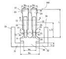
図1は本発明の実施1の形態に係わる逆相の屈曲モードで振動する音叉型圧電振動子100の平面図を示す。図1では、音叉腕に配置される電極と、基部部分に配置される電極とフレームに配置される電極は省略されている。音叉型圧電振動子100は基部部分30と、その基部部分30に接続された音叉腕10と音叉腕20と、基部部分30に接続された2個の接続部分31と接続部分32と、接続部分31に接続されたフレーム33と接続部分32に接続されたフレーム34とを備えて構成される。そして、音叉腕10と音叉腕20の各々の一端部は基部部分30に接続されている。 FIG. 1 is a plan view of a tuning-fork type
また、音叉腕10は第1振動部11と第2振動部12と第3振動部13とを少なくとも備えている。第1振動部11は第1幅W1を少なくとも備え、第2振動部12は第1幅W1より大きい第2幅W2を少なくとも備え、第3振動部13は第2幅W2より大きい第3幅W3を少なくとも備えていて、第1振動部11と第2振動部12は接続部分14を介して接続され、第2振動部12と第3振動部13は接続部分を介して接続されている。加えて、第1振動部11の上面に溝15が、下面に溝55(図2参照)が形成され、第2振動部12の上面に溝16が、下面に溝56(図3参照)が形成されている。同様に、音叉腕20は第1振動部21と第2振動部22と第3振動部23とを少なくとも備えている。第1振動部21は第1幅W1を少なくとも備え、第2振動部22は第1幅W1より大きい第2幅W2を少なくとも備え、第3振動部23は第2幅W2より大きい第3幅W3を少なくとも備えていて、第1振動部21と第2振動部22は接続部分24を介して接続され、第2振動部22と第3振動部23は接続部分を介して接続されている。加えて、第1振動部21の上面に溝25が、下面に溝65(図2参照)が形成され、第2振動部22の上面に溝26が、下面に溝66(図3参照)が形成されている。The
詳述するならば、フレーム33が一方の接続部分31を介して基部部分30に接続され、フレーム34が他方の接続部分32を介して基部部分30に接続される。さらに、本実施1の形態に係わる音叉型圧電振動子100は、フレーム33と固定フレーム34が収納される容器の固定部に導電性接着剤又は半田等で固定される。加えて、音叉腕10の第1振動部11と音叉腕20の第1振動部21の一端部が基部部分30に接続されている。そして、基部部分30に接続されたその一端部の幅は幅W1より大きく形成される。すなわち、音叉腕10の第1振動部11と音叉腕20の第1振動部21の各々は2個以上の複数の異なる幅を備えている。More specifically, the
さらに詳述するならば、音叉型圧電振動子100は基部部分30と、その基部部分30に接続された第1音叉腕10と第2音叉腕20と、その基部部分30に接続された第1接続部分31と第2接続部分32と、第1接続部分31に接続された第1フレーム33と第2接続部分32に接続された第2フレーム34とを備えて構成される。さらに、第1音叉腕10と第2音叉腕20の各々の一端部が基部部分30に接続され、他端部が自由である音叉型圧電振動子である。また、第1接続部分31と第2接続部分32の各々は第1端部と第2端部を備えていて、第1接続部分31と第2接続部分32の各々の第1端部が基部部分30に接続されると共に、第1接続部分31の第2端部が第1フレーム33の側面に接続され、かつ、第2接続部分32の第2端部が第2フレーム34の側面に接続されている。更に、第1フレーム33と第2フレーム34は音叉の叉部側と異なる音叉の外側に、第1音叉腕10と第2音叉腕20と共通の方向に延びて形成され、第1フレーム33と第2フレーム34は基部部分30に対して互いに反対の位置にある。また、第1音叉腕10と第2音叉腕20は長さ寸法Lを有している。本発明では、L/2の位置を第1長さ部分と呼び、接続部分14,24は第1長さ部分より短い基部部分30の側にある。 More specifically, the tuning fork type
さらに、第1音叉腕10と第2音叉腕20の第1幅W1と第2幅W2と第3幅W3との間には、W1<W2とW2<W3の関係がある。加えて、第1幅W1の溝幅をW1m、溝の長さをL1m、第2幅W2の溝幅をW2m、溝の長さをL2mとすると、W1m<W2mで、かつ、L1m>L2mの第1の関係、あるいはW1m=W2mで、かつ、L1m>L2mの第2の関係がある。第1と第2の両方の関係で、以下の段落0027で述べるように、等価直列抵抗Rmが従来のものと遜色のないものが得られる。加えて、音叉型圧電振動子の電気的等価回路における直列共振周波数をfm、品質係数をQm、Qmf=Qm/fmとすると、第1と第2の両方の関係で、Qmfは小さくなる。それ故、圧電発振回路での起動特性、すなわち、電源を入れたときの立ち上がり時間trはQmfに比例するので、立ち上がり時間trを短くできるという作用効果が奏される。Further, there is a relationship of W 1 <W 2 and W 2 <W 3 between the first width W 1 , the second width W 2, and the third width W 3 of the first
さらに詳述するならば、本発明では、音叉型圧電振動子の基本波モード振動の負性抵抗の絶対値|−RLm|と、基本波モード振動の品質係数Qmと等価直列抵抗Rmを備えた音叉型圧電振動子を少なくとも備えて構成される圧電発振回路の電源を入れたときに、圧電発振回路の出力信号が安定となる出力信号の80%に達したときの時間を立ち上がり時間trと定義される。そして、この定義の基で、第1の例として、tr<0.8秒の関係を得るには、4π+5Qmf<4π|−RLm|/Rmの関係により達成することができる。さらに、第2の例として、tr<0.5秒の関係を得るには、2π+4Qmf<2π|−RLm|/Rmの関係により達成することができる。加えて、第3の例として、tr<0.2秒の関係を得るには、2π+10Qmf<2π|−RLm|/Rmの関係により達成することができる。More specifically, in the present invention, the absolute value | −RL m | of the negative resistance of the fundamental mode vibration of the tuning fork type piezoelectric vibrator, the quality factor Q m of the fundamental mode vibration, and the equivalent series resistance R m The rise time is defined as the time when the output signal of the piezoelectric oscillation circuit reaches 80% when the piezoelectric oscillation circuit configured to include at least the tuning fork type piezoelectric vibrator including the power is turned on. It is defined as t r. Then, in this definition groups, as a first example, in order to obtain the relationship between t r <0.8 seconds, 4 π + 5Q mf <4 π | be accomplished by relation / R m | -RL m it can. Furthermore, as a second example, in order to obtain the relationship of t r <0.5 seconds, it can be achieved by the relationship of 2 π + 4Q mf <2 π | −RL m | / R m . In addition, as a third example, in order to obtain the relationship of t r <0.2 seconds, it can be achieved by the relationship of 2 π + 10Q mf <2 π | −RL m | / R m .
さらに、上記した作用効果に加えて、特に、W1m=W2mで、かつ、L1m>L2mの関係では、第1振動部の溝の側面に配置される電極とその電極に対抗して配置される電極の間の電界の強度と、第2振動部の溝の側面に配置される電極とその電極に対抗して配置される電極の間の電界の強度は異なる。それ故、音叉型圧電振動子を駆動する電荷量を音叉腕の位置で制御でき、例えば、2次高調波モード振動を抑制する電荷量にすることによって、基本波モード振動の励振を容易にすることができる作用効果が奏される。Further, in addition to the above-described effects, in particular, in the relationship of W 1m = W 2m and L 1m > L 2m , the electrode disposed on the side surface of the groove of the first vibrating part and the electrode The intensity of the electric field between the arranged electrodes is different from the intensity of the electric field between the electrode arranged on the side surface of the groove of the second vibrating part and the electrode arranged against the electrode. Therefore, the charge amount for driving the tuning fork type piezoelectric vibrator can be controlled by the position of the tuning fork arm. For example, by making the charge amount to suppress the second harmonic mode vibration, the fundamental mode vibration can be easily excited. The effect which can be performed is show | played.
また、基部部分30は幅W5を備えた第1基部部分と、幅W5より小さい幅W6を備えた第2基部部分と、幅W6より大きい幅W5を備えた第3基部部分を備えて構成されている。すなわち、第1音叉腕10と第2音叉腕20の各々の一端部は第1基部部分に接続されている。さらに、第2基部部分は第1基部部分と第3基部部分の間にあり、第1フレーム33は接続部分31を介して第3基部部分に接続され、第2フレーム34は接続部分32を介して第3基部部分に接続されている。加えて、接続部分31、32は長さL1を有し、L1は振動の漏れ(ここでは、振動による固定部での振動エネルギーの漏れをいう)に著しい影響を与える。それ故、振動の漏れの低減を図るために本実施1の形態では、L1は0.18mmより小さく、好ましくは、0.01mmより大きく0.075mmより小さく、より好ましくは、0.015mmより大きく0.04mmより小さい。また、本実施1の形態では、W5>W6の関係を有するが、本発明はこれに限定されるものではなく、W5=W6の関係も含む。次に、図1の音叉型圧電振動を駆動する音叉腕に配置される電極と、基部部分に配置される電極とフレームに配置される電極の配置について詳述する。The third base
図2は、図1の音叉型圧電振動子100の音叉腕10と音叉腕20の第1振動部11、21のA−Aの断面図を示す。図2において、第1振動部11、21の電極の配置について詳述する。音叉腕10の第1振動部11の上面には溝15が、下面には溝55が形成され、音叉腕20の第1振動部21の上面には溝25が、下面には溝65が形成されている。さらに、溝15には電極3が配置され、溝55には電極3と同極となる電極4が配置され、かつ、接続されている。また、溝25には電極7が配置され、溝65には電極7と同極となる電極8が配置され、かつ、接続されている。加えて、音叉腕10の第1振動部11の内側側面には電極2が配置され、その内側側面に対抗する外側側面には電極2と同極となる電極1が配置され、かつ、接続されている。同様に、音叉腕20の第1振動部21の内側側面には電極6が配置され、その内側側面に対抗する外側側面には電極6と同極となる電極5が配置され、かつ、接続されている。加えて、電極1、2、7、8は同極となる1電極端子を形成し、電極3、4、5、6は同極となる他の1電極端子を形成する。すなわち、2電極端子E1−E2が形成される。電極端子E1と電極端子E2は電気的極性が異なる、いわゆる互いに反対の電気的極性を有する。FIG. 2 is a cross-sectional view taken along line AA of the
また、一例として、電極端子E1の電極は基部部分30の面の上と接続部分31の面の上に配置された電極を介して第1フレーム33の面の上に配置された電極に接続され、かつ、電極端子E2の電極は基部部分30の面の上と接続部分32の面の上に配置された電極を介して第2フレーム34の面の上に配置された電極に接続される。Further, as an example, the electrode of the electrode terminal E 1 is connected to the electrode disposed on the surface of the
さらに、他の例として、電極端子E1の電極は基部部分30の面の上と接続部分32の面の上に配置された電極を介して第2フレーム34の面の上に配置された電極に接続され、かつ、電極端子E2の電極は基部部分30の面の上と接続部分31の面の上に配置された電極を介して第1フレーム33の面の上に配置された電極に接続される。Furthermore, as another example, the electrode of the electrode terminal E 1 is an electrode disposed on the surface of the
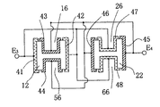
図3は、図1の音叉型圧電振動子100の音叉腕10と音叉腕20の第2振動部12、22のB−Bの断面図を示す。図3において、第2振動部12、22の電極の配置について詳述する。音叉腕10の第2振動部12の上面には溝16が、下面には溝56が形成され、音叉腕20の第2振動部22の上面には溝26が、下面には溝66が形成されている。さらに、溝16には電極43が配置され、溝56には電極43と同極となる電極44が配置され、かつ、接続されている。また、溝26には電極47が配置され、溝66には電極47と同極となる電極48が配置され、かつ、接続されている。加えて、音叉腕10の第2振動部12の内側側面には電極42が配置され、その内側側面に対抗する外側側面には電極42と同極となる電極41が配置され、かつ、接続されている。同様に、音叉腕20の第2振動部22の内側側面には電極46が配置され、その内側側面に対抗する外側側面には電極46と同極となる電極45が配置され、かつ、接続されている。すなわち、2電極端子E3−E4が形成される。加えて、電極端子E1と電極端子E3は同極に、電極端子E2と電極端子E4は同極になるように接続、形成されている。3 shows a cross-sectional view of the
詳述するならば、音叉腕10の第1振動部11の外側側面の電極1は接続部分14の面(例えば、側面及び/又は上下面)に配置された電極を介して第2振動部の外側側面の電極41に接続されている。さらに、音叉腕10の第1振動部11の内側側面の電極2は接続部分14(図4参照)の面(例えば、側面及び/又は上下面)に配置された電極を介して第2振動部の側面の電極45に接続されている。また、音叉腕10の第1振動部11の溝の電極3は接続部分14の面(例えば、溝の側面及び/又は上下面)に配置された電極を介して第2振動部の溝の電極43に接続されている。同様に、音叉腕20の第1振動部21の外側側面の電極5は接続部分24の面(例えば、側面及び/又は上下面)に配置された電極を介して第2振動部の外側側面の電極45に接続されている。さらに、音叉腕20の第1振動部21の内側側面の電極6は接続部分24の面(例えば、側面及び/又は上下面)に配置された電極を介して第2振動部の側面の電極46に接続されている。また、音叉腕20の第1振動部21の溝の電極7は接続部分24の面(例えば、溝の側面及び/又は上下面)に配置された電極を介して第2振動部の溝の電極47に接続されている。 In detail, the
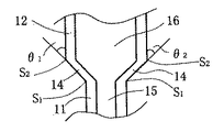
次に、第1振動部と第2振動部と接続部分との関係について詳述する。図4には、音叉腕10の溝15を備えた第1振動部11と溝16を備えた第2振動部12と接続部分14の平面図の拡大図を示す。左側の接続部分14と第2振動部12の間には角度θ1を、右側の接続部分14と第2振動部の間には角度θ2を持って接続部分14と第2振動部12は形成されている。本実施1に係わる形態では、角度θ1と角度θ2は化学的エッチング加工できる任意の値を持つが、好ましくは、角度θ1と角度θ2はθ1、θ2≦90°の関係を満たすように形成される。さらに、角度θ1側で、圧電効果により接続部分が第1振動部と第2振動部と同じ方向の第1歪を引き起こし、かつ、角度θ2側で、圧電効果により接続部分が第1振動部と第2振動部と同じ方向の第2歪を引き起こし、第1歪と第2歪の方向が反対のときには、θ1、θ2<30°の関係が好ましいが、より好ましくは、θ1、θ2≦20°の関係を満たすよう形成される。なお、第1振動部11の一端部(第1端部)と接続部分14の一端部(第1端部)が接続する点をS1で示し、第2振動部12の一端部(第1端部)と接続部分14の他端部(第2端部)が接続する点をS2で示す。同様に、音叉腕20については、音叉腕10を音叉腕20に、溝幅15、16を溝幅25,26に、第1振動部11を第1振動部21に、第2振動部12を第2振動部22に、接続部分14を接続部分24にそれぞれ置き換えることによって、音叉腕20の関係が得られる。また、角度θ1と角度θ2は音叉腕10と同じ関係を有する。Next, the relationship between the first vibration part, the second vibration part, and the connection part will be described in detail. FIG. 4 shows an enlarged plan view of the first vibrating
なお、本実施1の形態では、角度θ1と角度θ2が設けられているが、本発明はこれに限定されるものではなく、角度θ1と角度θ2のどちらか一個を各音叉腕に設けてもよい。加えて、溝15と溝16は繋がって形成されているが、溝15と溝16は分割されていてもよい。この場合には、分割された溝15に配置された電極3は分割する面に配置された電極を介して分割された溝16に配置された電極43に接続される。この分割された溝と溝との電極の関係は以下に述べる溝と溝との関係にも適用できる。同様に、溝25と溝26は繋がって形成されているが、溝25と溝26は分割されていてもよい。同じことが溝55と溝56に言え、かつ、同じことが溝65と溝66にも言える。In the
また、図2と図3に示した溝の断面形状は矩形をしているが、この矩形の断面形状は加工方法によって異なる形状となることは言うまでもない。すなわち、本発明はこの矩形の断面形状に限定されるものではなく、本発明は加工方法によって異なる断面の形状をも包含するものである。例えば、音叉型圧電振動子が水晶から形成された音叉型屈曲水晶振動子(音叉腕の幅方向が水晶の電気軸方向に、長さ方向が機械軸方向にそれぞれ大略一致して形成される)で、フッ酸等による化学的エッチングによって溝を形成した場合には、水晶の電気軸と垂直となる+x面と−x面ではエッチング速度が異なるので、−x面は溝の深さ方向に直線的に加工されるが、+x面は溝の深さ方向に傾きを持って形成され、溝の幅の半分の位置で、厚み方向に引いた中心線(溝の断面の厚み方向の中立線)に対して非対称な断面形状となる。また、音叉の叉部分から音叉腕の長さ方向に引いた線、いわゆる中心線に対して音叉腕10と音叉腕20は大略対称に形成される。好ましくは、完全な対称がよいが、振動子加工によるバラツキが生じるために略対称となる。 Moreover, although the cross-sectional shape of the groove | channel shown in FIG. 2 and FIG. 3 is a rectangle, it cannot be overemphasized that this rectangular cross-sectional shape becomes a shape which changes with processing methods. That is, the present invention is not limited to this rectangular cross-sectional shape, and the present invention includes cross-sectional shapes that differ depending on the processing method. For example, a tuning-fork-type bending crystal resonator in which a tuning-fork type piezoelectric resonator is made of quartz (formed so that the tuning fork arm width direction is substantially coincident with the crystal electrical axis direction and the length direction is substantially coincident with the mechanical axis direction). When the groove is formed by chemical etching with hydrofluoric acid or the like, the etching rate is different between the + x plane and the −x plane perpendicular to the electric axis of the crystal, and therefore the −x plane is linear in the depth direction of the groove. However, the + x plane is formed with an inclination in the depth direction of the groove, and the center line (neutral line in the thickness direction of the cross section of the groove) drawn in the thickness direction at half the width of the groove The cross-sectional shape is asymmetric with respect to. Further, the
上述したように、本実施1の形態に係わる音叉型圧電振動子100は、基部部分30と、基部部分30に接続された第1音叉腕10と第2音叉腕20とを備えて構成され、第1音叉腕10と第2音叉腕20の各々の一端部が基部部分30に接続され、他端部が自由である音叉型圧電振動子で、第1音叉腕10は第1幅W1を備えた第1振動部11と第1幅W1より大きい第2幅W2を備えた第2振動部12とを少なくとも備えていて、第1振動部11と第2振動部12の各振動部の上面と下面の各々には溝が形成されると共に、第1振動部11の側面と第2振動部12の側面は接続部分14の側面を介して接続され、接続部分14は第1音叉腕10の第1長さ部分(半分の長さ(L/2))より短い基部部分30の側にあり、かつ、第2音叉腕20は第1幅W1を備えた第1振動部21と第1幅W1より大きい第2幅W2を備えた第2振動部22とを少なくとも備えていて、第1振動部21と第2振動部22の各振動部の上面と下面の各々には溝が形成されると共に、第1振動部21の側面と第2振動部22の側面は接続部分24の側面を介して接続され、接続部分24は第2音叉腕20の第1長さ部分(半分の長さ(L/2))より短い基部部分30の側にあるように構成されている。この構成により、より小型化しても、等価直列抵抗Rmの増加を抑えた音叉型圧電振動子が得られることを次に説明する。As described above, the tuning fork type
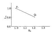
まず、等価直列抵抗Rmを求める関係式を示す。次に、本実施1に係わる形態の音叉型圧電振動子の振動子サイズと等価直列抵抗との関係を従来のものと比較して説明する。以下順次説明する。音叉型圧電振動子の電気的等価回路の等価インダクタンスをLm、音叉腕の最大振幅Dと最大振幅電圧V0との間の比例係数をkaとすると、等価直列抵抗RmはRm=(Lm/kb)1/2/kaで与えられる。但し、kbは音叉腕の厚みを一定とすると、音叉腕の面積S(=音叉腕の幅Wx音叉腕の長さ)に比例する。この関係により等価直列抵抗Rmを求めることができる。また、段落0002に記載された特許文献1の重りの効果を備えた形状で、かつ、長さ2mmの圧電ユニットに収納される音叉型圧電振動子を振動子1とし、また本実施1に係わる形態の音叉型圧電振動子を振動子2としたときの振動子1の等価直列抵抗で規格化した等価直列抵抗Rnと振動子1の音叉腕の長さで規格化した音叉腕の長さLnとの関係を図7に示す。すなわち、振動子1のRn=1とLn=1に対する振動子2のRnとLnとの関係である。したがって、振動子1の(Rn、Ln)を(1.0、1.0)(点P1)とすると、振動子1に対する振動子2の(Rn、Ln)は(1.23、0.82)(点Q1)となる。換言するならば、振動子1の等価直列抵抗と音叉腕の長さとを比較して、振動子2の等価直列抵抗は23%と若干増加するが、それ以上に音叉腕の長さを18%と著しく短くすることができる。このように、本発明の振動子2は従来の振動子1と遜色のない等価直列抵抗を備え、かつ、圧電ユニットの長さを短くできるので、1.8mmより小さい超小型の圧電ユニットが実現できるという作用効果が奏される。First, a relational expression for determining the equivalent series resistance R m. Next, the relationship between the vibrator size and the equivalent series resistance of the tuning fork type piezoelectric vibrator according to the first embodiment will be described in comparison with the conventional one. This will be sequentially described below. A proportionality coefficient between the equivalent inductance of the electrical equivalent circuit of the tuning fork type piezoelectric vibrator and L m, the maximum amplitude D and the maximum amplitude voltage V 0 which tuning fork arms and k a, the equivalent series resistance R m is R m = is given by (L m / k b) 1/2 / k a. However, k b is when the constant thickness of the tuning fork arms, proportional to the area of the tuning fork arms S (= length of the width Wx tuning fork arms of the tuning fork arm). It can be determined equivalent series resistance R m by this relationship. Further, a tuning fork type piezoelectric vibrator having a weight effect described in paragraph 0002 described in paragraph 0002 and housed in a piezoelectric unit having a length of 2 mm is used as the
なお、本実施1に係わる形態の音叉型圧電振動子はW2<W3の関係を備えているが、本発明はこれに限定されるものではなく、W2=W3の関係をも包含するものである。また、接続部分14と接続部分24は音叉腕の第1長さ部分より短い基部部分30の側にあるように形成されているが、本発明はこれに限定されるものではなく、図6で詳述されるように、それら接続部分は音叉腕の第1長さ部分より長い先端部分の側に、または第1長さ部分に等しくなるように形成しても同様の効果が得られる。The tuning fork type piezoelectric vibrator according to the first embodiment has a relationship of W 2 <W 3 , but the present invention is not limited to this, and includes a relationship of W 2 = W 3. To do. Moreover, although the
図5は本発明の実施2の形態に係わる逆相の屈曲モードで振動する音叉型圧電振動子120の平面図を示す。図5では、音叉腕に配置される電極と、基部部分に配置される電極とフレームに配置される電極は省略されている。音叉型圧電振動子120は基部部分90と、その基部部分90に接続された音叉腕70と音叉腕80と、基部部分90に接続された2個の接続部分91と接続部分92と、接続部分91に接続されたフレーム93と接続部分92に接続されたフレーム94とを備えて構成される。音叉腕70と音叉腕80の各々の一端部は基部部分90に接続されている。また、音叉腕70は第1振動部71と第2振動部72と第3振動部73と第4振動部74と第5振動部75とを少なくとも備えている。第1振動部71は第1幅W11を少なくとも備え、第2振動部72は第2幅W22を少なくとも備え、第3振動部73は第3幅W33を少なくとも備え、第4振動部74は第4幅W44を少なくとも備え、第5振動部75は第5幅W55を少なくとも備えていて、第1振動部71と第2振動部72は図1と同じように接続部分を介して接続されている。加えて、第2振動部72と第3振動部73の接続、及び第3振動部73と第4振動部74の接続も図1と同じように接続部分を介して接続される。加えて、第1振動部71の上面に溝76が、第2振動部72の上面に溝77が、第3振動部73の上面に溝78が、第4振動部74の上面に溝79が形成されている。FIG. 5 is a plan view of a tuning-fork type
音叉腕70と同じ様に、音叉腕80は第1幅W11を少なくとも備えた第1振動部81と、第2幅W22を少なくとも備えた第2振動部82と、第3幅W33を少なくとも備えた第3振動部83と、第4幅W44を少なくとも備えた第4振動部84と、第5幅W55を少なくとも備えた第5振動部85とを少なくとも備えている。第1振動部81と第2振動部82は図1と同じように接続部分を介して接続されている。また、第2振動部82と第3振動部83の接続、及び第3振動部83と第4振動部84の接続も図1と同じように接続部分を介して接続される。加えて、第1振動部81の上面に溝86が、第2振動部82の上面に溝87が、第3振動部83の上面に溝88が、第4振動部84の上面に溝89が形成されている。さらに、図示されていないが、音叉腕70と音叉腕80の上面に形成された溝に対抗して音叉腕の下面にも溝が形成されている。また、各腕幅は、W11<W22<W33<W44<W55の関係を有する。なお、本発明での各振動部の幅とは各振動部の最も小さい幅のことをいう。In the same way as the
このように、本実施2の形態に係わる音叉型圧電振動子では、互いに異なる幅を備えた3個の振動部が第1長さ部分より短い基部部分の側にあるが、本発明は上記3個の振動部に限定されるものではなく、互いに異なる幅を備えた3個より多い振動部を第1長さ部分より短い基部部分の側に形成してもよい。そして、好ましくは、基部部分90に接続される振動部の幅が他の振動部の幅より小さく形成される。加えて、互いに異なる幅を備えた3個の振動部が第1長さ部分より長い先端部分の側にあるが、本発明は上記3個の振動部に限定されるものではなく、互いに異なる幅を備えた3個より多い振動部を第1長さ部分より長い先端部分の側に形成してもよい。すなわち、互いに異なる幅を備えた複数個の振動部が第1長さ部分より長い先端部分の側に形成され、かつ、複数個の振動部の内の少なくとも1個の振動部の上下面に溝が形成されている。そして、好ましくは、先端部分の振動部(振動部Aという)の幅が基部部分90に接続された幅W11より大きく形成されるか、あるいは先端部の振動部Aに接続される振動部(振動部Bという)の幅が基部部分90に接続された幅W11より大きく形成される。As described above, in the tuning fork type piezoelectric vibrator according to the second embodiment, the three vibrating parts having different widths are on the side of the base part shorter than the first length part. The number of vibrating parts is not limited to a single vibrating part, and more than three vibrating parts having different widths may be formed on the side of the base part shorter than the first length part. Preferably, the width of the vibration part connected to the
上述したように、本実施2の形態に係わる音叉型圧電振動子120は、基部部分90と、基部部分90に接続された第1音叉腕70と第2音叉腕80とを備えて構成され、第1音叉腕70と第2音叉腕80の各々の一端部が基部部分90に接続され、他端部が自由である音叉型圧電振動子で、第1音叉腕70は第1幅W11を備えた第1振動部71と、第1幅W11より大きい第2幅W22を備えた第2振動部72と、第2幅W22より大きい第3幅W33を備えた第3振動部73と、第3幅W33より大きい第4幅W44を備えた第4振動部74と、第4幅W44より大きい第5幅W55を備えた第5振動部75とを少なくとも備えていて、第1振動部71と第2振動部72と第3振動部73と第4振動部74の各振動部の上面と下面の各々には溝が形成されると共に、第1振動部71の側面と第2振動部72の側面は接続部分(接続部分S12という)の側面を介して接続され、第2振動部72の側面と第3振動部73の側面は接続部分(接続部分S23という)の側面を介して接続され、第3振動部73の側面と第4振動部74の側面は接続部分(接続部分S34という)の側面を介して接続され、第4振動部74の側面と第5振動部75の側面は接続部分(接続部分S45という)の側面を介して接続されていて、接続部分S12と接続部分S23は第1音叉腕70の第1長さ部分より短い基部部分90の側にある。加えて、接続部分S34と接続部分S45は第1長さ部分より長い先端部分の側にある。As described above, the tuning fork type piezoelectric vibrator 120 according to the second embodiment is configured to include the base portion 90, the first tuning fork arm 70 and the second tuning fork arm 80 connected to the base portion 90, and a first fork arm 70 one end of each of the second tuning fork arms 80 is connected to the base portion 90, in the tuning fork type piezoelectric vibrator other end is free, the first fork arm 70 the first width W 11 a first vibrating portion 71 having a third oscillation section having a second vibrating portion 72 having a first width W 11 larger than the second width W 22, the second width W 22 larger than the third width W 33 and 73, a fourth vibration unit 74 having a fourth width W 44 larger than the third width W 33, fifth equipped at least with a vibration unit 75 having a fourth width W 44 is larger than the fifth width W 55 The upper and lower surfaces of the first vibrating portion 71, the second vibrating portion 72, the third vibrating portion 73, and the fourth vibrating portion 74 Together with the groove is formed in each side surface and the side surface of the second vibrating portion 72 of the first vibrating portion 71 is connected through the side of the connection portion (that the connection portion S 12), the second vibrating portion 72 side surface and the side surface of the third vibrating unit 73 is connected through a side of the connection portion (that the connection portion S 23), side surfaces and a fourth vibration portion 74 of the third vibrating portion 73 connecting portion (connecting portion S 34 It is connected via the side surfaces of) of the side surface and the side surface of the fifth vibration portion 75 of the fourth oscillating unit 74 is connected via the side of the connection portion (that the connection portions S 45), the connecting portion S 12 The connecting portion S 23 is on the side of the base portion 90 that is shorter than the first length portion of the first tuning fork arm 70. In addition, the connection portion S 34 and the connection portion S 45 are on the side of the tip portion longer than the first length portion.
第1音叉腕70と同じ様に、第2音叉腕80は第1幅W11を備えた第1振動部81と、第1幅W11より大きい第2幅W22を備えた第2振動部82と、第2幅W22より大きい第3幅W33を備えた第3振動部83と、第3幅W33より大きい第4幅W44を備えた第4振動部84と、第4幅W44より大きい第5幅W55を備えた第5振動部85とを少なくとも備えていて、第1振動部81と第2振動部82と第3振動部83と第4振動部84の各振動部の上面と下面の各々には溝が形成されると共に、第1振動部81の側面と第2振動部82の側面は接続部分(接続部分S12という)の側面を介して接続され、第2振動部82の側面と第3振動部83の側面は接続部分(接続部分S23という)の側面を介して接続され、第3振動部83の側面と第4振動部84の側面は接続部分(接続部分S34という)の側面を介して接続され、第4振動部84の側面と第5振動部85の側面は接続部分(接続部分S45という)の側面を介して接続されていて、接続部分S12と接続部分S23は第2音叉腕80の第1長さ部分より短い基部部分90の側にある。加えて、接続部分S34と接続部分S45は第1長さ部分より長い先端部分の側にある。すなわち、互いに異なる幅を備えた少なくとも2個の振動部が第1長さ部分より短い基部部分90の側にあり、互いに異なる幅を備えた少なくとも2個の振動部が第1長さ部分より長い先端部分の側にある。In the same manner as the first fork arm 70, the second vibrating portion and the second tuning fork arms 80 with the first vibrating portion 81 having a first width W 11, the first width W 11 larger than the second width W 22 and 82, a third vibration unit 83 having a second width W 22 larger than the third width W 33, and the fourth oscillation unit 84 having a fourth width W 44 larger than the third width W 33, the fourth width Each of the vibrations of the first vibration part 81, the second vibration part 82, the third vibration part 83, and the fourth vibration part 84 is provided with at least a fifth vibration part 85 having a fifth width W 55 larger than W 44 . with upper and lower surfaces of the respective groove parts are formed, side surfaces of the second vibrating portion 82 of the first vibrating portion 81 is connected through the side of the connection portion (that the connection portion S 12), the side surface and the side surface of the third vibrating part 83 of the second vibrating portion 82 are connected through the side of the connection portion (that the connection portion S 23), 3 side and the side surface of the fourth vibration portion 84 of the vibrating portion 83 is connected through the side of the connection portion (referred to as connection portions S 34), the side surface and the side surface of the fifth vibration portion 85 of the fourth vibrating portion 84 connecting portion be connected via the side surface of the (called connection portions S 45), the connection portion S 12 and the connecting portion S 23 is on the side of the base portion 90 shorter than the first length of the second tuning fork arms 80. In addition, the connection portion S 34 and the connection portion S 45 are on the side of the tip portion longer than the first length portion. That is, at least two vibration parts having different widths are on the side of the
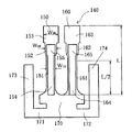
図6は本発明の実施3の形態に係わる逆相の屈曲モードで振動する音叉型圧電振動子140の平面図を示す。図6では、音叉腕に配置される電極と、基部部分に配置される電極とフレームに配置される電極は省略されている。音叉型圧電振動子140は基部部分170と、その基部部分170に接続された音叉腕150と音叉腕160と、基部部分170に接続された2個の接続部分171と接続部分172と、接続部分171に接続されたフレーム173と接続部分172に接続されたフレーム174とを備えて構成される。音叉腕150と音叉腕160の各々の一端部は基部部分170に接続されている。また、音叉腕150は第1振動部151と第2振動部152と第3振動部153とを少なくとも備えている。第1振動部151は第1幅W10を少なくとも備え、第2振動部152は第2幅W20を少なくとも備え、第3振動部153は第3幅W30を少なくとも備えていて、第1振動部151と第2振動部152は図1と同じように接続部分を介して接続されている。加えて、第2振動部152と第3振動部153の接続も接続部分を介して接続される。加えて、第1振動部151の上面に溝154が、第2振動部152の上面に溝155が形成されている。さらに、図示されていないが、第1振動部151の下面と第2振動部152の下面にも溝が形成されている。FIG. 6 is a plan view of a tuning-fork type
音叉腕150と同じ様に、音叉腕160は第1振動部161と第2振動部162と第3振動部163とを少なくとも備えている。第1振動部161は第1幅W10を少なくとも備え、第2振動部162は第2幅W20を少なくとも備え、第3振動部163は第3幅W30を少なくとも備えていて、第1振動部161と第2振動部162は図1と同じように接続部分を介して接続されている。加えて、第2振動部162と第3振動部163の接続も接続部分を介して接続される。加えて、第1振動部161の上面に溝164が、第2振動部162の上面に溝165が形成されている。Similar to the
さらに、図示されていないが、第1振動部161の下面と第2振動部162の下面にも溝が形成されている。また、各腕幅は、W10<W20<W30の関係を有する。さらに、第2振動部152、162の長さをL20、その第2振動部152、162に形成された溝の長さをL2gとすると、L2g<L20、又はL2g=L20の関係がある。加えて、第3振動部153、163の長さをL30とすると、L2g<L30、又はL20<L30、又は.L20=L30の関係がある。さらに、第1振動部の溝幅をW10m、第2振動部の溝幅をW20mとすると、W10m<W20m又はW10m=W20m又はW10m>W20mの関係がある。また、Wh12はWh12=W20/W10で定義され、Wh23はWh23=W30/W20で定義されるとき、Wh12とWh23の各々は1.06より大きく、好ましくは、1.08〜3.0の範囲内に、より好ましくは、1.2〜2.7の範囲内にある。その結果、第1振動部と第2振動部の溝の効果と第3振動部の重りの効果により、等価直列抵抗Rmの増加を抑えた超小型の音叉型圧電振動子が得られる。Further, although not shown, grooves are also formed on the lower surface of the first vibrating
このように、本実施3の形態に係わる音叉型圧電振動子では、互いに異なる幅を備えた3個の振動部が第1長さ部分より長い先端部分の側にあるが、本発明は上記3個の振動部に限定されるものではなく、互いに異なる幅を備えた3個より多い振動部を第1長さ部分より長い先端部分の側に形成してもよい。そして、好ましくは、互いに異なる幅を備えた少なくとも2個の振動部の上面と下面に溝が形成される。さらに、第1振動部151、161と第2振動部152、162には図1で示したと同様の電極が配置されている。すなわち、2電極端子を形成する。 As described above, in the tuning fork type piezoelectric vibrator according to the third embodiment, the three vibrating parts having different widths are on the side of the tip part longer than the first length part. The number of vibrating portions is not limited to the number of vibrating portions, and more than three vibrating portions having different widths may be formed on the side of the tip portion longer than the first length portion. Preferably, grooves are formed on the upper and lower surfaces of at least two vibration parts having different widths. Furthermore, electrodes similar to those shown in FIG. 1 are arranged on the first vibrating
加えて、第3振動部153、163の上面と下面の少なくとも一面に周波数調整用の金属の重りが形成されている。その重りの厚みは0.2μmより厚く、好ましくは、0.5μmから3.2μmの範囲内に、より好ましくは、0.75μmから2.6μmの範囲内にある。また、図6に示すように、第1振動部151、161と第2振動部152、162と第3振動部153、163の各々は、長さ方向に一定の幅を少なくとも備えて構成されている。しかし、本発明はこれに限定されるものではなく、本発明は第1振動部と第2振動部と第3振動部の各々、あるいは少なくとも1個の振動部が、音叉先端部に向かって徐々に広がる、あるいは狭くなる形状をも包含するものである。 In addition, a metal weight for frequency adjustment is formed on at least one of the upper and lower surfaces of the third vibrating
上述したように、本実施3の形態に係わる音叉型圧電振動子140は、基部部分170と、基部部分170に接続された第1音叉腕150と第2音叉腕160とを備えて構成され、第1音叉腕150と第2音叉腕160の各々の一端部が基部部分170に接続され、他端部が自由である音叉型圧電振動子で、第1音叉腕150は第1幅W10を備えた第1振動部151と、第1幅W10より大きい第2幅W20を備えた第2振動部152と、第2幅W20より大きい第3幅W30とを少なくとも備えていて、第1振動部151と第2振動部152の各振動部の上面と下面の各々には溝が形成されると共に、第1振動部151の側面と第2振動部152の側面は接続部分(接続部分S12という)の側面を介して接続され、第2振動部152の側面と第3振動部153の側面は接続部分(接続部分S23という)の側面を介して接続されていて、接続部分S12と接続部分S23は第1音叉腕150の第1長さ部分より長い先端部分の側にある。As described above, the tuning fork type
第1音叉腕150と同じ様に、第2音叉腕160は第1幅W10を備えた第1振動部161と、第1幅W10より大きい第2幅W20を備えた第2振動部162と、第2幅W20より大きい第3幅W30とを少なくとも備えていて、第1振動部161と第2振動部162の各振動部の上面と下面の各々には溝が形成されると共に、第1振動部161の側面と第2振動部162の側面は接続部分(接続部分S12という)の側面を介して接続され、第2振動部162の側面と第3振動部163の側面は接続部分(接続部分S23という)の側面を介して接続されていて、接続部分S12と接続部分S23は第2音叉腕160の第1長さ部分より長い先端部分の側にある。In the same manner as the first
例えば、音叉型圧電振動子140は第2長さ部分(3L/5の位置)と、第3長さ部分(5L/7)と第4長さ部分(3L/4の位置)を備えていて、音叉型圧電振動子140の第2振動部152、162の各々は第2長さ部分と第4長さ部分の間にある。好ましくは、第2長さ部分と第3長さ部分の間にある。 For example, the tuning fork type
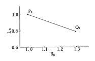
次に、本実施3に係わる形態の音叉型圧電振動子の振動子サイズと等価直列抵抗との関係を従来のものと比較して説明する。段落0002に記載された特許文献1の重りの効果を備えた形状で、かつ、長さ2mmの圧電ユニットに収納される音叉型圧電振動子を振動子1とし、また本実施3に係わる形態の音叉型圧電振動子を振動子3としたときの振動子1の等価直列抵抗で規格化した等価直列抵抗Rnと振動子1の音叉腕の長さで規格化した音叉腕の長さLnとの関係を図8に示す。すなわち、振動子1のRn=1とLn=1に対する振動子3のRnとLnとの関係である。したがって、振動子1の(Rn、Ln)を(1.0、1.0)(点P2)とすると、振動子1に対する振動子3の(Rn、Ln)は(1.29、0.77)(点Q2)となる。Next, the relationship between the vibrator size and the equivalent series resistance of the tuning fork type piezoelectric vibrator according to the third embodiment will be described in comparison with the conventional one. A tuning-fork type piezoelectric vibrator having a weight effect described in paragraph 0002 and having a weight effect of 2 mm and housed in a piezoelectric unit having a length of 2 mm is used as the
換言するならば、振動子1の等価直列抵抗と音叉腕の長さと比較して、振動子3の等価直列抵抗は29%増加するが、音叉腕の長さは23%短くなる。このように、振動子3の等価直列抵抗は振動子1の等価直列抵抗より若干増加するが、それにもまして、音叉腕の長さを23%短くできるという極めて優れた作用効果が奏される。その結果、1.8mm以下(例えば、1.6mm)の超小型の圧電ユニットが実現できる。と同時に、その圧電ユニットを備えた圧電発振器が実現できるという作用効果が同時にもたらされる。さらに特筆すべきことは、圧電発振器の増幅器を従来のものを変更せずに使用できることである。 In other words, compared with the equivalent series resistance of the
なお、本実施3の形態に係わる音叉型圧電振動子140では、基部部分170に接続される音叉腕150、160の第1振動部151、161の一端部の幅は第1振動部の幅W10より大きく形成される。この関係は本発明の他の音叉型圧電振動子にも適用される。In the tuning fork type
さらに、本実施3の形態に係わる音叉型圧電振動子140では、接続部分S12は各音叉腕の第1長さ部分より長い先端部分の側にあるが、本発明はこれに限定されるものではなく、本発明の接続部分S12は第1長さ部分と等しい位置にあってもよい。さらに詳述するならば、図4で述べたように、例えば、角度θ1と角度θ2はθ1、θ2=90°の関係を満たすように形成されるときには、接続部分のS1とS2は第1長さ部分と同じ長さの位置にある。また、θ1、θ2<90°の関係のときには、第1長さ部分は接続部分のS1とS2の間にあるか、接続部分のS1は第1長さ部分と同じ長さの位置にあるか、あるいは接続部分のS2は第1長さ部分と同じ長さの位置にある。加えて、θ1、θ2>90°の関係のときには、接続部分のS1は第1長さ部分と同じ長さの位置にあり、本発明は上記関係を全て包含するものである。Furthermore, those in the tuning fork type
また、本実施3の形態に係わる音叉型圧電振動子140では、各腕幅は、W10<W20<W30の関係を有するが、本発明はこれに限定されるものではなく、W10<W20=W30の関係も本発明に含まれる。加えて、W10<W20=W30の関係のときには、第2振動部に溝が形成される部分(溝の長さL2g)と溝のない部分(Lng)が存在する。それ故、本発明はL2g<Lng、又はL2g=Lng、又はL2g>Lngの関係を含むが、特に重り効果を必要とするときには、L2g<Lngの関係が好ましく、特に等価直列抵抗Rmの低下を必要とするときには、L2g>Lngの関係が好ましい。Further, in the tuning fork type
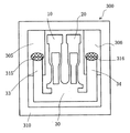
図9は本発明の実施1の形態に係わる圧電ユニット300の平面図である。表面実装型のケース310には固定部305と固定部306が設けられている。また、圧電ユニット300はすでに述べた実施1の形態に係わる音叉型圧電振動子100とケース310と蓋(図示されていない)とを備えて構成されている。更に詳述するならば、音叉型圧電振動子100のフレーム33とフレーム34はケース310に設けられた固定部305と固定部306にそれぞれ導電性接着剤315と導電性接着剤316や半田によって固定される。又、ケース310と蓋は金属やガラスなどの接合部材を介して接合される。すなわち、音叉型圧電振動子100と、その音叉型圧電振動子を収納するケースと、そのケースの開口部をカバーする蓋とを備えて圧電ユニットは構成される。また、固定部は蓋に設けても良い。蓋はガラスまたは金属またはガラスと金属で作られている。 FIG. 9 is a plan view of the
さらに詳述するならば、ケース310は第1固定部305と第2固定部306とを備え、第1固定部305と第2固定部306は第1音叉腕10(図1参照)と第2音叉腕20(図1参照)に対して互いに反対の位置にあって、音叉型圧電振動子100の第1フレーム33は第1固定部305に固定され、かつ、その第2フレーム34は第2固定部306に固定され、第1フレーム33の面の上に配置された電極(図示されていない)は、第1固定部305の面の上に配置された電極(図示されていない)に接続され、かつ、第2フレーム34の面の上に配置された電極(図示されていない)は、第2固定部306の面の上に配置された電極(図示されていない)に接続される。また、第1フレーム33の面の上に配置された電極と第2フレーム34の面の上に配置された電極とは電気的極性が異なる。 More specifically, the
この実施1の形態では、第1フレーム33は第1固定部305に導電性接着剤315によって固定されると共に、第1フレーム33の面の上に配置された電極は、導電性接着剤315を介して第1固定部の面の上に配置された電極に接続される。すなわち、導電性接着剤315によって第1フレーム33の固定と、第1フレーム33の電極と第1固定部の電極との接続を同時に行う。同様に、第2フレーム34は第2固定部306に導電性接着剤316によって固定されると共に、第2フレーム34の面の上に配置された電極は、導電性接着剤316を介して第2固定部の面の上に配置された電極に接続される。すなわち、導電性接着剤316によって第2フレーム34の固定と、第2フレーム34の電極と第2固定部の電極との接続を同時に行う。 In the first embodiment, the
図10は本発明の実施1の形態に係わる圧電発振器を構成する圧電発振回路図の一例である。圧電発振回路201は増幅器202(CMOSインバータ)と、帰還抵抗204と、ドレイン抵抗207と、コンデンサ205,206と圧電振動子203を備えて構成されている。すなわち、圧電発振回路201は増幅器202と帰還抵抗204とを備えて構成される増幅回路208と、ドレイン抵抗207とコンデンサ205とコンデンサ206とケースに固定された圧電振動子203とを備えて構成される帰還回路209とを備えて構成される。詳細には、本発明の圧電発振回路は増幅回路と帰還回路を備えて構成されていて、増幅回路は少なくとも増幅器から構成され、帰還回路は少なくとも圧電振動子とコンデンサとを備えて構成されている。又、本発明の圧電発振器の圧電発振回路に用いられる圧電振動子は実施1から実施3の形態に係わる音叉型圧電振動子が用いられ、その音叉型圧電振動子は容器(ユニット)に収納されている。いわゆる、圧電ユニットが圧電発振回路に用いられる。そして、本発明の圧電発振器の出力信号は電子機器の表示部に時間情報を表示するための信号として用いられる。 FIG. 10 is an example of a piezoelectric oscillation circuit diagram constituting the piezoelectric oscillator according to the first embodiment of the present invention. The
次に、音叉型圧電振動子と圧電ユニットと圧電発振器と電子機器の各々の製造方法について詳述する。本実施1の形態に係わる音叉型圧電振動子を製造する工程では、まず、図1に示した音叉腕10、20と基部部分30と第1接続部分31と第2接続部分32と第1フレーム33と第2フレーム34とを備えた音叉形状が、エッチング加工により一体に形成される。すなわち、第1エッチング加工によりその音叉形状が形成される。次に、音叉腕10、20の上面と下面の各々に溝がエッチング加工により形成される。すなわち、第2エッチング加工により溝が形成される。その後に、図2と図3に示した電極が音叉腕の側面と溝の中に形成される。と同時に、基部部分の面の上と第1接続部分と第2接続部分と第1フレームと第2フレームの各々の面の上に電極が形成される。すなわち、2電極端子を備えた音叉型圧電振動子が形成される。この製造工程は本実施2と本実施3の各々の形態に係わる音叉型圧電振動子に適用できる。 Next, a manufacturing method of each of the tuning fork type piezoelectric vibrator, the piezoelectric unit, the piezoelectric oscillator, and the electronic device will be described in detail. In the process of manufacturing the tuning fork type piezoelectric vibrator according to the first embodiment, first, the
次に、圧電ユニットを製造する工程では、音叉型圧電振動子の第1フレームと第2フレームがケースの固定部に固定される。その後に、蓋がケースの開口部に接続される。すなわち、図9に示した圧電ユニットが形成される。さらに、圧電発振器を製造する工程では、その圧電ユニットを構成する音叉型圧電振動子の2電極端子が増幅器とコンデンサと抵抗とに電気的に接続される。すなわち、図10で示した圧電発振回路が形成され、その圧電発振回路を備えた圧電発振器が形成される。次に、電子機器を製造する工程では、その圧電発振器の出力信号が電子機器の動作用信号となるように接続される。 Next, in the process of manufacturing the piezoelectric unit, the first frame and the second frame of the tuning fork type piezoelectric vibrator are fixed to the fixing portion of the case. Thereafter, the lid is connected to the opening of the case. That is, the piezoelectric unit shown in FIG. 9 is formed. Further, in the process of manufacturing the piezoelectric oscillator, the two electrode terminals of the tuning fork type piezoelectric vibrator constituting the piezoelectric unit are electrically connected to the amplifier, the capacitor, and the resistor. That is, the piezoelectric oscillation circuit shown in FIG. 10 is formed, and a piezoelectric oscillator including the piezoelectric oscillation circuit is formed. Next, in the step of manufacturing the electronic device, the piezoelectric oscillator is connected so that the output signal of the piezoelectric oscillator becomes the operation signal of the electronic device.
なお、本実施1の形態に係わる音叉型圧電振動子を製造する工程では、音叉腕を形成した後に、音叉腕に溝を形成しているが、本発明はこれに限定されるものではなく、音叉腕と溝を同時に形成してもよい。あるいは溝を形成した後に、音叉腕を形成してもよい。 In the process of manufacturing the tuning fork type piezoelectric vibrator according to the first embodiment, after the tuning fork arm is formed, the groove is formed in the tuning fork arm, but the present invention is not limited to this. The tuning fork arm and the groove may be formed simultaneously. Alternatively, the tuning fork arm may be formed after the groove is formed.
本発明の音叉型圧電振動子と圧電ユニットと圧電発振器は小型化しても従来のものと遜色のない等価直列抵抗を備えているので、より小型化された音叉型圧電振動子と圧電ユニットを特に必要とする携帯電話などの携帯機器や民生機器を含む電子機器に適用できる。 Since the tuning fork type piezoelectric vibrator, the piezoelectric unit and the piezoelectric oscillator of the present invention have equivalent series resistances that are comparable to the conventional ones even if they are miniaturized, the tuning fork type piezoelectric vibrator and the piezoelectric unit that are more miniaturized are particularly suitable. Applicable to electronic devices including portable devices such as mobile phones and consumer devices that need them.
L 音叉腕の長さ
L1 接続部分の長さ、
L/2 第1長さ部分
3L/5 第2長さ部分
5L/7 第3長さ部分
3L/4 第4長さ部分
W1 第1振動部の幅
W2 第2振動部の幅
W3 第3振動部の幅
14、24 第1振動部と第2振動部を接続する接続部分
33 第1フレーム、
34 第2フレームL length of tuning fork arm L 1 length of connecting portion,
L / 2 first length portion 3L / 5 second length portion 5L / 7 3 lengths 3L / 4 fourth length portion W 1 width of the first vibrating portion W 2 second vibrating portion width W 3 of
34 Second frame
Claims (9)
第1音叉腕と第2音叉腕の各音叉腕は第1幅W1を少なくとも備えた第1振動部と、第1幅W1より大きい第2幅W2を少なくとも備えた第2振動部と、を少なくとも備え、第1振動部は第2振動部より基部部分の側にあって、
第1振動部の側面は接続部分の側面を介して第2振動部の側面に接続され、前記接続部分の側面は第1音叉腕と第2音叉腕の各音叉腕の第1長さ部分より長い音叉腕の先端部分の側にあり、
幅の比W12がW12=W2/W1で定義されるとき、W12は1.2〜2.7の範囲内にあることを特徴とする圧電振動子。A base portion, a first tuning fork arm, and a second tuning fork arm are provided. Grooves are formed on each of the upper and lower surfaces of each tuning fork arm of the first tuning fork arm and the second tuning fork arm. Piezoelectric vibrator with electrodes arranged on the
Each tuning fork arm of the first fork arm and the second tuning fork arms and the second vibrating section having at least a first vibrating section having at least a first width W 1, the first width W 1 greater than the second width W 2 The first vibrating part is closer to the base part than the second vibrating part,
The side surface of the first vibration part is connected to the side surface of the second vibration part via the side surface of the connection part, and the side surface of the connection part is from the first length part of each tuning fork arm of the first tuning fork arm and the second tuning fork arm. On the tip of the long tuning fork arm,
When the width ratio W 12 is defined by W 12 = W 2 / W 1 , the piezoelectric vibrator is characterized in that W 12 is in a range of 1.2 to 2.7.
Priority Applications (1)
| Application Number | Priority Date | Filing Date | Title |
|---|---|---|---|
| JP2017079278A JP6263719B2 (en) | 2017-03-27 | 2017-03-27 | Piezoelectric vibrator, piezoelectric unit, piezoelectric oscillator and electronic device |
Applications Claiming Priority (1)
| Application Number | Priority Date | Filing Date | Title |
|---|---|---|---|
| JP2017079278A JP6263719B2 (en) | 2017-03-27 | 2017-03-27 | Piezoelectric vibrator, piezoelectric unit, piezoelectric oscillator and electronic device |
Related Parent Applications (1)
| Application Number | Title | Priority Date | Filing Date |
|---|---|---|---|
| JP2015102257A Division JP6131445B2 (en) | 2015-04-27 | 2015-04-27 | Piezoelectric vibrator and piezoelectric unit |
Publications (2)
| Publication Number | Publication Date |
|---|---|
| JP2017143571A JP2017143571A (en) | 2017-08-17 |
| JP6263719B2 true JP6263719B2 (en) | 2018-01-24 |
Family
ID=59628777
Family Applications (1)
| Application Number | Title | Priority Date | Filing Date |
|---|---|---|---|
| JP2017079278A Active JP6263719B2 (en) | 2017-03-27 | 2017-03-27 | Piezoelectric vibrator, piezoelectric unit, piezoelectric oscillator and electronic device |
Country Status (1)
| Country | Link |
|---|---|
| JP (1) | JP6263719B2 (en) |
Families Citing this family (1)
| Publication number | Priority date | Publication date | Assignee | Title |
|---|---|---|---|---|
| EP3468036A1 (en) * | 2017-10-03 | 2019-04-10 | Micro Crystal AG | Small piezoelectric resonator |
Family Cites Families (3)
| Publication number | Priority date | Publication date | Assignee | Title |
|---|---|---|---|---|
| JP2006203458A (en) * | 2005-01-19 | 2006-08-03 | Seiko Epson Corp | Piezoelectric vibrating piece and piezoelectric device using the same |
| JP2007013910A (en) * | 2005-05-31 | 2007-01-18 | Sanyo Electric Co Ltd | Piezoelectric resonator |
| JP2007096900A (en) * | 2005-09-29 | 2007-04-12 | Seiko Epson Corp | Piezoelectric vibrating piece and piezoelectric device |
-
2017
- 2017-03-27 JP JP2017079278A patent/JP6263719B2/en active Active
Also Published As
| Publication number | Publication date |
|---|---|
| JP2017143571A (en) | 2017-08-17 |
Similar Documents
| Publication | Publication Date | Title |
|---|---|---|
| JP4026074B2 (en) | Crystal unit, crystal unit and crystal oscillator | |
| JP2013243753A (en) | Method for manufacturing crystal vibrator, crystal unit and crystal oscillator | |
| JP2004135357A (en) | Quartz crystal unit, crystal unit, crystal oscillator and their manufacturing method | |
| JP5130502B2 (en) | Piezoelectric vibrator and piezoelectric oscillator | |
| JP6263719B2 (en) | Piezoelectric vibrator, piezoelectric unit, piezoelectric oscillator and electronic device | |
| JP6131445B2 (en) | Piezoelectric vibrator and piezoelectric unit | |
| JP5756983B2 (en) | Piezoelectric vibrator, piezoelectric unit, piezoelectric oscillator and electronic equipment | |
| JP5526312B2 (en) | Piezoelectric vibrator, piezoelectric unit, piezoelectric oscillator and electronic equipment | |
| JP6454894B2 (en) | Piezoelectric vibrator, piezoelectric unit, piezoelectric oscillator and electronic device | |
| JP4411495B2 (en) | Crystal unit with a bent crystal unit | |
| JP2003273703A (en) | Quartz vibrator and its manufacturing method | |
| JP2017121093A6 (en) | Piezoelectric vibrator, piezoelectric unit, piezoelectric oscillator and electronic device | |
| JP4411494B2 (en) | Crystal oscillator | |
| JP3749917B2 (en) | Manufacturing method of crystal oscillator | |
| JP2005094733A (en) | Resonator, resonator unit, oscillator, electronic apparatus and manufacturing method thereof | |
| JP2012227932A (en) | Piezoelectric vibrator, piezoelectric unit, piezoelectric oscillator and electronic equipment, and manufacturing method thereof | |
| JP2005094726A (en) | Crystal unit, manufacturing method thereof and crystal oscillator | |
| JP4074934B2 (en) | Crystal oscillator and manufacturing method thereof | |
| JP2003273696A (en) | Method for manufacturing crystal unit and method of manufacturing crystal oscillator | |
| JP4411496B6 (en) | Portable device equipped with crystal oscillator and manufacturing method thereof | |
| JP4411496B2 (en) | Portable device equipped with crystal oscillator and manufacturing method thereof | |
| JP2005094732A (en) | Crystal resonator, crystal unit and crystal oscillator | |
| JP4411492B2 (en) | Quartz crystal unit, crystal unit, crystal oscillator and information communication equipment | |
| JP4411492B6 (en) | Quartz crystal unit, crystal unit, crystal oscillator and information communication equipment | |
| JP2014042224A (en) | Piezoelectric vibrator, piezoelectric unit, piezoelectric oscillator, electronic apparatus, and method for manufacturing them |
Legal Events
| Date | Code | Title | Description |
|---|---|---|---|
| A975 | Report on accelerated examination |
Free format text: JAPANESE INTERMEDIATE CODE: A971005 Effective date: 20170531 |
|
| A131 | Notification of reasons for refusal |
Free format text: JAPANESE INTERMEDIATE CODE: A131 Effective date: 20170808 |
|
| A521 | Request for written amendment filed |
Free format text: JAPANESE INTERMEDIATE CODE: A523 Effective date: 20170817 |
|
| TRDD | Decision of grant or rejection written | ||
| A01 | Written decision to grant a patent or to grant a registration (utility model) |
Free format text: JAPANESE INTERMEDIATE CODE: A01 Effective date: 20171017 |
|
| A61 | First payment of annual fees (during grant procedure) |
Free format text: JAPANESE INTERMEDIATE CODE: A61 Effective date: 20171113 |
|
| R150 | Certificate of patent or registration of utility model |
Ref document number: 6263719 Country of ref document: JP Free format text: JAPANESE INTERMEDIATE CODE: R150 |
|
| R250 | Receipt of annual fees |
Free format text: JAPANESE INTERMEDIATE CODE: R250 |