JP6262676B2 - Hydraulic drive unit for construction machinery - Google Patents
Hydraulic drive unit for construction machinery Download PDFInfo
- Publication number
- JP6262676B2 JP6262676B2 JP2015022564A JP2015022564A JP6262676B2 JP 6262676 B2 JP6262676 B2 JP 6262676B2 JP 2015022564 A JP2015022564 A JP 2015022564A JP 2015022564 A JP2015022564 A JP 2015022564A JP 6262676 B2 JP6262676 B2 JP 6262676B2
- Authority
- JP
- Japan
- Prior art keywords
- pressure
- valve
- pressure oil
- pump
- control valve
- Prior art date
- Legal status (The legal status is an assumption and is not a legal conclusion. Google has not performed a legal analysis and makes no representation as to the accuracy of the status listed.)
- Active
Links
Images


Description
本発明は、油圧式ショベル等の建設機械の油圧駆動装置に係わり、特に、2つの吐出ポートを有しかつ単一のポンプレギュレータ(ポンプ制御装置)によって吐出流量が制御されるポンプ装置を含む2つ以上の可変容量型のポンプ装置を備え、これら複数のポンプ装置により複数のアクチュエータを駆動する建設機械の油圧駆動装置に関する。 The present invention relates to a hydraulic drive device for a construction machine such as a hydraulic excavator, and particularly includes a pump device having two discharge ports and whose discharge flow rate is controlled by a single pump regulator (pump control device). The present invention relates to a hydraulic drive device for a construction machine that includes one or more variable displacement pump devices and drives a plurality of actuators by the plurality of pump devices.
特許文献1には、2つの吐出ポートを有するスプリットフロー型の油圧ポンプと、シングルフロー型の油圧ポンプとを備え、これら2つの油圧ポンプにより複数のアクチュエータを駆動するとともに、それぞれの油圧ポンプがロードセンシング制御を行う油圧ショベルの油圧駆動装置が提案されている。ロードセンシング制御とは、複数のアクチュエータの最高負荷圧を検出し、油圧ポンプ(メインポンプ)の吐出圧がその最高負荷圧より目標差圧だけ高くなるよう油圧ポンプの吐出流量を制御するポンプ制御方式である。この特許文献1に記載の油圧駆動装置において、複数のアクチュエータはアームシリンダとブームシリンダを含み、アームシリンダはスプリットフロー型の油圧ポンプからの吐出油により駆動され、ブームシリンダは、要求流量が少ないときはシングルフロー型の油圧ポンプからの吐出油により駆動され、要求流量が増大したときはスプリットフロー型とシングルフロー型の両方の油圧ポンプからの吐出油が合流して駆動される。
通常の1ポンプロードセンシング制御を行う油圧駆動装置においては、油圧ポンプの吐出圧は常に複数のアクチュエータの最高負荷圧よりもある設定圧分だけ高くなるように制御されるため、負荷圧の高いアクチュエータと負荷圧の低いアクチュエータを複合して駆動する場合(例えば、ブーム上げ(負荷圧:高)とアームクラウド(負荷圧:低)操作を同時に行う、所謂水平均し動作を行った場合など)には、油圧ポンプの吐出圧はブームシリンダの高い負荷圧よりもある設定圧分だけ高くなるように制御される。このとき、負荷圧の低いアームシリンダに流量が流れすぎるのを防ぐために設けられたアーム用の圧力補償弁が絞られるため、この絞りの圧力損失のために無駄な動力を消費していた。 In a hydraulic drive device that performs normal one-pump load sensing control, the discharge pressure of the hydraulic pump is always controlled to be higher than the maximum load pressure of a plurality of actuators by a set pressure. And actuators with low load pressure (for example, when performing so-called water averaging operation that simultaneously performs boom raising (load pressure: high) and arm cloud (load pressure: low) operations) The discharge pressure of the hydraulic pump is controlled to be higher by a set pressure than the high load pressure of the boom cylinder. At this time, since the pressure compensation valve for the arm provided to prevent the flow rate from flowing excessively into the arm cylinder having a low load pressure is throttled, useless power is consumed due to the pressure loss of the throttle.
特許文献1記載の油圧駆動装置によれば、ブームシリンダは要求流量が少ないときはシングルフロー型の油圧ポンプからの吐出油により駆動されるため、アーム用の油圧ポンプとブーム用の油圧ポンプとを分離した状態でロードセンシング制御が行われる。これにより水平均し動作を行った場合、ブームシリンダの負荷圧が高く、アームシリンダの負荷圧が低くても、負荷圧の低いアーム用の圧力補償弁による絞りの圧力損失を低減し、無駄な動力損失を低減することができる。
According to the hydraulic drive device described in
また、水平均し動作はブーム上げのハーフ操作(ブームシリンダ小流量)とアームクラウドのフル操作(アームシリンダ大流量)との組み合わせで行う。このためオープンセンタ回路を形成するオープンセンタ型の流量制御弁を用いる油圧駆動装置と比べた場合においても、ブーム上げハーフ操作によるブーム用の制御弁(オープンセンタ型の流量制御弁)からのブリードオフ損失や、分流のために設けたパラレル絞りの圧力損失を著しく低減し、無駄な動力損失を低減することができる。 Further, the water averaging operation is performed by a combination of a half operation of raising the boom (a small flow rate of the boom cylinder) and a full operation of the arm cloud (a large flow rate of the arm cylinder). For this reason, even when compared with a hydraulic drive device using an open center type flow control valve forming an open center circuit, the bleed-off from the boom control valve (open center type flow control valve) by the boom raising half operation Loss and pressure loss of the parallel throttle provided for the diversion can be remarkably reduced, and useless power loss can be reduced.
しかしながら、特許文献1記載の従来技術においても、下記の問題があった。
However, the prior art described in
特許文献1記載の油圧駆動装置においては、走行複合操作以外の操作では、スプリットフロー型油圧ポンプの一方の吐出ポートに接続された圧油供給路と他方の吐出ポートに接続された圧油供給路は切換弁によって遮断されており、それぞれの吐出油が独立してアクチュエータに供給される。また、2つの吐出ポートの一方の吐出油が供給されるアクチュエータにはバケットシリンダや2つの走行モータの一方などが含まれ、2つの吐出ポートの他方の吐出油が供給されるアクチュエータには2つの走行モータの他方などが含まれている。
In the hydraulic drive device described in
このような回路構成において、例えばバケット単独動作を行うべく操作装置を操作した場合、スプリットフロー型油圧ポンプの一方の吐出ポートから要求流量に見合う流量の圧油を吐出すべく、スプリットフロー型油圧ポンプはその吐出ポートの吐出流量を増加させる。このとき、一方の吐出ポートから吐出される圧油の流量増加に伴い、もう一方の吐出ポートから吐出される圧油の流量も増加するが、この圧油は圧油供給路に設けられたアンロード弁によってタンクに排出される。しかし、アンロード弁は排出流量が増加するにしたがって圧油供給路の圧力を上昇させるオーバライド特性を有しているため、吐出ポートから吐出される圧油の流量が増加し排出流量が増加すると、それにしたがって圧油供給路の圧力を上昇させ、その圧力と排出流量(吐出ポートから吐出される圧油の流量)を乗じた値に比例した動力が無駄になってしまう。バケット単独動作においては、スプリットフロー型油圧ポンプの一方の吐出ポートからバケットシリンダに供給される流量は比較的大きいため、もう一方の吐出ポートから供給される圧油がアンロード弁によって排出されることで無視できない無駄な動力損失が発生する。 In such a circuit configuration, for example, when an operating device is operated to perform a single bucket operation, a split flow hydraulic pump is used to discharge pressure oil at a flow rate that matches the required flow rate from one discharge port of the split flow hydraulic pump. Increases the discharge flow rate of the discharge port. At this time, as the flow rate of the pressure oil discharged from one discharge port increases, the flow rate of the pressure oil discharged from the other discharge port also increases. However, this pressure oil is supplied to the pressure oil supply passage. It is discharged into the tank by the load valve. However, since the unload valve has an override characteristic that increases the pressure in the pressure oil supply passage as the discharge flow rate increases, if the flow rate of the pressure oil discharged from the discharge port increases and the discharge flow rate increases, Accordingly, the pressure proportional to the value obtained by multiplying the pressure of the pressure oil supply passage by the pressure multiplied by the discharge flow rate (the flow rate of the pressure oil discharged from the discharge port) is wasted. In the bucket single operation, the flow rate supplied from one discharge port of the split flow type hydraulic pump to the bucket cylinder is relatively large, so the pressure oil supplied from the other discharge port is discharged by the unload valve. A wasteful power loss that cannot be ignored is generated.
また、走行ピボットターン動作(一方の走行がフル動作、他方が非操作)を行う場合においても、上記バケット単独動作の場合と同様に、非操作側の吐出ポートから吐出された圧油が圧油供給路に接続されたアンロード弁を介してタンクに排出される際に、オーバライド特性によって圧力が上昇してしまい、同様に無駄な動力損失が発生する。 In addition, when performing a traveling pivot turn operation (one traveling is a full operation and the other is not operated), the pressure oil discharged from the non-operating side discharge port is the pressure oil as in the case of the bucket single operation. When the fuel is discharged to the tank via the unload valve connected to the supply path, the pressure rises due to the override characteristic, and similarly, wasteful power loss occurs.
本発明の目的は、第1及び第2吐出ポートを有する可変容量型の第1ポンプ装置と第3吐出ポートを有する可変容量型の第2ポンプ装置を備えた油圧駆動装置において、オープンセンタ型の流量制御弁のブリードオフ損失や分流のために設けたパラレル絞りの圧力損失、或いは非操作側アンロード弁からの圧油排出時の圧力上昇などによる無駄な動力損失を発生させずに、水平均し動作などの複合操作やバケット単独動作や走行ピボットターン動作などのアクチュエータの単独駆動を行うことができ、エネルギ効率の高い建設機械の油圧駆動装置を提供することである。 An object of the present invention is to provide an open center type hydraulic drive device including a variable displacement type first pump device having first and second discharge ports and a variable displacement type second pump device having a third discharge port. Water average without causing bleed-off loss of flow control valve, pressure loss of parallel throttle provided for shunting, or wasteful power loss due to pressure rise when pressure oil is discharged from non-operating side unload valve It is an object of the present invention to provide a hydraulic drive device for a construction machine with high energy efficiency, which can perform a single operation of an actuator such as a combined operation such as a chopping operation, a single bucket operation or a traveling pivot turn operation.
上記の目的を達成するために、本発明は、第1及び第2吐出ポートを有する可変容量型の第1ポンプ装置と、第3吐出ポートを有する可変容量型の第2ポンプ装置と、前記第1及び第2ポンプ装置の前記第1、第2及び第3吐出ポートから吐出された圧油により駆動される複数のアクチュエータと、前記第1、第2及び第3吐出ポートと前記複数のアクチュエータとの間に配置され、前記第1、第2及び第3吐出ポートから前記複数のアクチュエータに供給される圧油の流れを制御する第1及び第2弁装置と、前記第1ポンプ装置の第1及び第2吐出ポートから吐出される圧油の流量を制御する第1ポンプ制御装置と、 前記第2ポンプ装置の第3吐出ポートから吐出される圧油の流量を制御する第2ポンプ制御装置とを備えた建設機械の油圧駆動装置において、前記第1弁装置は前記第1ポンプ装置の第1及び第2吐出ポートに接続され、オープンセンタ回路を形成する複数のオープンセンタ型の流量制御弁を含み、前記第2弁装置は前記第2ポンプ装置の第3吐出ポートに接続され、クローズドセンタ回路を形成する複数のクローズドセンタ型の流量制御弁を含み、前記第2ポンプ制御装置は、前記第2ポンプ装置の第3吐出ポートから吐出された圧油の圧力が、この圧油による駆動されるアクチュエータの最高負荷圧より目標差圧だけ高くなるよう前記第2ポンプ装置の容量を制御するロードセンシング制御部を有し、前記複数のアクチュエータはある複合操作において同時に駆動される第1及び第2アクチュエータを含み、前記第1弁装置は、前記第1ポンプ装置の第1及び第2吐出ポートの少なくとも一方から前記第1アクチュエータに供給される圧油の流れを制御するオープンセンタ型の第1流量制御弁を含み、前記第2弁装置は、前記第2ポンプ装置の第3吐出ポートから前記第2アクチュエータに供給される圧油の流れを制御するクローズドセンタ型の第2流量制御弁を含むものとする。 To achieve the above object, the present invention provides a variable displacement first pump device having first and second discharge ports, a variable displacement second pump device having a third discharge port, A plurality of actuators driven by pressure oil discharged from the first, second and third discharge ports of the first and second pump devices, the first, second and third discharge ports and the plurality of actuators; Between the first, second and third discharge ports to control the flow of pressure oil supplied to the plurality of actuators, and the first pump device And a first pump control device that controls the flow rate of the pressure oil discharged from the second discharge port, and a second pump control device that controls the flow rate of the pressure oil discharged from the third discharge port of the second pump device. Construction machine oil with In the drive device, the first valve device includes a plurality of open center type flow control valves connected to the first and second discharge ports of the first pump device and forming an open center circuit, and the second valve device. Includes a plurality of closed center type flow control valves connected to a third discharge port of the second pump device to form a closed center circuit, and the second pump control device includes a third discharge of the second pump device. A load sensing control unit that controls the capacity of the second pump device so that the pressure of the pressure oil discharged from the port is higher than the maximum load pressure of the actuator driven by the pressure oil by a target differential pressure; The plurality of actuators include first and second actuators that are simultaneously driven in a composite operation, and the first valve device includes first and second actuators of the first pump device. An open center type first flow rate control valve for controlling a flow of pressure oil supplied to the first actuator from at least one of the second discharge ports, the second valve device being a third of the second pump device; A closed center type second flow control valve for controlling the flow of pressure oil supplied from the discharge port to the second actuator is included.
このように第1弁装置に第1アクチュエータに供給される圧油の流れを制御するオープンセンタ型の第1流量制御弁を設け、第2弁装置に第2アクチュエータに供給される圧油の流れを制御するクローズドセンタ型の第2流量制御弁を設けることにより、第1アクチュエータをアームシリンダとして用い、第2アクチュエータをブームシリンダとして用いて水平均し動作を行った場合、ブームシリンダはロードセンシング制御を行う第2ポンプ装置により駆動され、アームシリンダは別の第1ポンプ装置により駆動されるため、負荷圧の低いアームシリンダ側での圧力補償弁の絞りの圧力損失、小流量のブームシリンダ側でのオープンセンタ型の流量制御弁のブリードオフ損失及び分流のために設けたパラレル絞りの圧力損失などによる無駄な動力損失を発生させずに水平均し動作を行うことができる。 In this way, the first valve device is provided with an open center type first flow control valve for controlling the flow of pressure oil supplied to the first actuator, and the flow of pressure oil supplied to the second actuator is provided in the second valve device. If the first actuator is used as an arm cylinder and the second actuator is used as a boom cylinder to perform a water average operation by providing a closed center type second flow control valve that controls the boom cylinder, load sensing control is performed. Since the arm cylinder is driven by another first pump device, the pressure loss of the throttle of the pressure compensation valve on the arm cylinder side where the load pressure is low, and on the boom cylinder side where the small flow rate is Waste due to the bleed-off loss of the open center type flow control valve and the pressure loss of the parallel throttle provided for the diversion It is possible to perform horizontal leveling operation without causing power loss.
また、第1及び第2の2つの吐出ポートを有する第1ポンプ装置側の第1弁装置にオープンセンタ回路を形成する複数のオープンセンタ型の流量制御弁を設けることにより、第1ポンプ装置の一方の吐出ポートから吐出される圧油の流量増加に伴い、他方の吐出ポートから吐出される圧油の流量が増加しても、その圧油は中立位置にあるオープンセンタ型の流量制御弁のセンタバイパス油路を介してタンクに排出されるため、他方の吐出ポートの吐出油がアンロード弁からタンクに排出されるときの圧力上昇による無駄な動力損失を発生させずにバケット単独動作や走行ピボットターン動作などのアクチュエータの単独駆動を行うことができる。 Further, by providing a plurality of open center type flow control valves for forming an open center circuit in the first valve device on the first pump device side having the first and second discharge ports, the first pump device Even if the flow rate of the pressure oil discharged from the other discharge port increases as the flow rate of the pressure oil discharged from one discharge port increases, the pressure oil remains in the neutral position of the open center type flow control valve. Since the oil is discharged to the tank via the center bypass oil passage, the bucket can be operated independently and run without causing unnecessary power loss due to pressure rise when the oil discharged from the other discharge port is discharged from the unload valve to the tank. Actuator single drive such as pivot turn operation can be performed.
本発明によれば、第1及び第2吐出ポートを有する可変容量型の第1ポンプ装置と第3吐出ポートを有する可変容量型の第2ポンプ装置を備えた油圧駆動装置において、オープンセンタ型の流量制御弁のブリードオフ損失や分流のために設けたパラレル絞りの圧力損失、或いは非操作側アンロード弁からの圧油排出時の圧力上昇などによる無駄な動力損失を発生させずに、水平均し動作などの複合操作やバケット単独動作や走行ピボットターン動作などのアクチュエータの単独駆動を行うことができ、エネルギ効率の高い建設機械の油圧駆動装置を提供することができる。 According to the present invention, in a hydraulic drive device including a variable displacement type first pump device having first and second discharge ports and a variable displacement type second pump device having a third discharge port, an open center type Water average without causing bleed-off loss of flow control valve, pressure loss of parallel throttle provided for shunting, or wasteful power loss due to pressure rise when pressure oil is discharged from non-operating side unload valve It is possible to perform a single operation of an actuator such as a combined operation such as a slidable operation, a single bucket operation, and a traveling pivot turn operation, and a hydraulic drive device for a construction machine with high energy efficiency can be provided.
<第1の実施の形態>
〜構成〜
図1は、本発明の第1の実施の形態に係わる油圧ショベル(建設機械)の油圧駆動装置を示す図である。
<First Embodiment>
~Constitution~
FIG. 1 is a diagram showing a hydraulic drive device of a hydraulic excavator (construction machine) according to a first embodiment of the present invention.
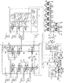
図1において、本実施の形態の油圧駆動装置は、原動機(例えばディーゼルエンジン)1と、その原動機1によって駆動され、第1及び第2圧油供給路105,205に圧油を吐出する第1及び第2吐出ポート102a,102bを有するスプリットフロー型の可変容量型メインポンプ102(第1ポンプ装置)と、原動機1によって駆動され、第3圧油供給路305に圧油を吐出する第3吐出ポート202aを有するシングルフロータイプの可変容量型メインポンプ202(第2ポンプ装置)と、メインポンプ102の第1及び第2吐出ポート102a,102b及びメインポンプ202の第3吐出ポート202aから吐出される圧油により駆動される複数のアクチュエータ3a,3b,3c,3d,3e,3f,3g,3hと、第1及び第2圧油供給路105,205に接続され、メインポンプ102の第1及び第2吐出ポート102a,102bから複数のアクチュエータ3a〜3hのうちのアクチュエータ3a,3b,3c,3d,3f,3gに供給される圧油の流れ(流量と方向)を制御する第1コントロールバルブユニット4(第1弁装置)と、第3圧油供給路305に接続され、メインポンプ202の第3吐出ポート202aから複数のアクチュエータ3a〜3hのうちのアクチュエータ3a,3e,3fに供給される圧油の流れ(流量と方向)を制御する第2コントロールバルブユニット5(第2弁装置)と、メインポンプ102の第1及び第2吐出ポート102a,102bの吐出流量を制御するためのレギュレータ112(第1ポンプ制御装置)と、メインポンプ202の第3吐出ポート202aの吐出流量を制御するためのレギュレータ212(第2ポンプ制御装置)とを備えている。
In FIG. 1, a hydraulic drive device according to the present embodiment is driven by a prime mover (for example, a diesel engine) 1 and a
コントロールバルブユニット4は、第1圧油供給路105に接続され、オープンセンタ型回路を形成する、メインポンプ102の第1吐出ポート102aからアクチュエータ3b,3c,3d,3fに供給される圧油の流れ(流量と方向)を制御する複数のオープンセンタ型の流量制御弁16i,16c,16d,16fと、第2圧油供給路205に接続され、オープンセンタ型回路を形成する、メインポンプ102の第2吐出ポート102bからアクチュエータ3a,3b,3gに供給される圧油の流れ(流量と方向)を制御する複数のオープンセンタ型の流量制御弁16a,16b,16gと、第1圧油供給路105に接続され、第1圧油供給路105の圧力を設定圧力以上にならないように制御するメインリリーフ弁114と、第2圧油供給路205に接続され、第2圧油供給路205の圧力を設定圧力以上にならないように制御するメインリリーフ弁214とを備えている。
The control valve unit 4 is connected to the first pressure
コントロールバルブユニット5は、第3圧油供給路305に接続され、クローズドセンタ回路を形成する、メインポンプ202の第3吐出ポート202aからアクチュエータ3a,3e,3hに供給される圧油の流れ(流量と方向)を制御する複数のクローズドセンタ型の流量制御弁6a,6e,6hと、複数の流量制御弁6a,6e,6hの前後差圧が目標差圧に等しくなるよう複数の流量制御弁6a,6e,6hの前後差圧をそれぞれ制御する複数の圧力補償弁7a,7e,7hと、流量制御弁6a,6e,6hと圧力補償弁7a,7e,7hとの間の油路に配置された逆流防止用のチェックバルブ8a,8e,8hと、第3圧油供給路305に接続され、第3圧油供給路305の圧力を設定圧力以上にならないように制御するメインリリーフ弁314と、第3圧油供給路305に接続され、第3圧油供給路305の圧力が第3吐出ポート202aから吐出される圧油によって駆動されるアクチュエータ3a,3e,3fの最高負荷圧にバネの設定圧力(所定圧力)を加算した圧力(アンロード弁セット圧)よりも高くなると開状態になって第3圧油供給路305の圧油をタンクに戻すアンロード弁315とを備えている。
The control valve unit 5 is connected to the third pressure
コントロールバルブユニット5は、また、第3圧油供給路305に接続される流量制御弁6a,6e,6hの負荷ポートに接続され、アクチュエータ3a,3e,3fの最高負荷圧Plmaxを検出するシャトル弁9a,9eを含む負荷圧検出回路131と、第3圧油供給路305の圧力(すなわち第3吐出ポート202aの圧力)P3と負荷圧検出回路131によって検出された最高負荷圧Plmax(第3圧油供給路305に接続されるアクチュエータ3a,3e,3fの最高負荷圧)との差圧であるLS差圧を絶対圧Plsとして出力する差圧減圧弁311とを備えている。
The control valve unit 5 is also connected to the load port of the flow
負荷圧検出回路131によって検出された最高負荷圧Plmaxはアンロード弁315に導かれ、差圧減圧弁311が出力するLS差圧Plsは第3圧油供給路305に接続された圧力補償弁7a,7e,7hとメインポンプ202のレギュレータ212に導かれる。
The maximum load pressure Plmax detected by the load pressure detection circuit 131 is guided to the unload
アクチュエータ3aは、例えば油圧ショベルのブームを駆動するブームシリンダ(第2アクチュエータ)であり、アクチュエータ3bは、例えば油圧ショベルのアームを駆動するアームシリンダ(第1アクチュエータ)である。ブームシリンダ3a及びアームシリンダ3bは、他のアクチュエータよりも最大の要求流量が大きいアクチュエータであり、かつブームシリンダ3aとアームシリンダ3bはある複合操作において同時に駆動されるアクチュエータである。また、複合操作の一例にブーム上げ(負荷圧:高)とアームクラウド(負荷圧:低)操作を同時に行う水平均し動作があり、この水平均し動作においてブームシリンダ3aはアームシリンダ3bよりも要求流量の少ないアクチュエータである。
The
アクチュエータ3cは、例えば油圧ショベルの上部旋回体を駆動する旋回モータであり、アクチュエータ3dは、例えば油圧ショベルのバケットを駆動するバケットシリンダであり、アクチュエータ3eは、例えば油圧ショベルのスイングポストを駆動するスイングシリンダであり、アクチュエータ3f,3gは、それぞれ、例えば油圧ショベルの下部走行体の左右の履帯を駆動する左走行モータ及び右走行モータであり、アクチュエータ3hは、例えば油圧ショベルのブレードを駆動するブレードシリンダである。
The actuator 3c is, for example, a swing motor that drives an upper swing body of a hydraulic excavator, the
コントロールバルブユニット4において、流量制御弁16a(第3流量制御弁)はブームシリンダ3aを増速するためのアシスト駆動用(以下ブームアシスト駆動用という)であり、流量制御弁16b,16i(第1流量制御弁)はアームシリンダ3b用(以下アーム用という)であり、流量制御弁16cは旋回モータ3c用(以下旋回用という)であり、流量制御弁16dはバケットシリンダ3d用(以下バケット用という)であり、流量制御弁16f,16gは左右の走行モータ3f,3g用(以下左右走行用という)である。
In the control valve unit 4, the flow control valve 16a (third flow control valve) is for assist driving (hereinafter referred to as boom assist driving) for accelerating the
コントロールバルブユニット5において、流量制御弁6a(第2流量制御弁)はブームシリンダ3aのメイン駆動用(以下ブームメイン駆動用という)であり、流量制御弁6eはスイングシリンダ3e用(以下スイング用という)であり、流量制御弁6hはブレードシリンダ3h用(以下ブレード用という)である。
In the control valve unit 5, the flow control valve 6a (second flow control valve) is for main drive of the
コントロールバルブユニット4において、左走行用の流量制御弁16f、旋回用の流量制御弁16c、バケット用の流量制御弁16d、アーム用の流量制御弁16iは、上流側からその記載順序で、第1圧油供給路105に接続されたセンタバイパスライン106上にタンデム回路を形成するよう接続され、アーム用の流量制御弁16b、ブームアシスト駆動用の流量制御弁16a、右走行用の流量制御弁16gは、上流側からその記載順序で、第2圧油供給路205に接続されたセンタバイパスライン206上にタンデム回路を形成するよう接続されている。また、旋回用の流量制御弁16cとバケット用の流量制御弁16dとはタンデム回路と並行にパラレル回路を形成するよう油路17aを介して接続され、アーム用の流量制御弁16bとブームアシスト駆動用の流量制御弁16aとはタンデム回路と並行にパラレル回路を形成するよう油路17bを介して接続されている。流量制御弁16c,16d,16i及び流量制御弁16b,16a,16gのメータイン回路に逆流防止用のチェックバルブ18b,18c,18d,18f,18h,18iが設けられ、パラレル回路の油路17aに逆流防止用のチェックバルブ18eが設けられている。
In the control valve unit 4, the flow control valve 16f for left travel, the
また、アーム用の流量制御弁16bには再生回路19Aが設けられている。再生回路19Aはアームクラウド動作をさせるためにアームシリンダ3bを伸び方向に駆動する際に、アームシリンダ3bのロッド側からの戻り油の一部をアームシリンダ3bのボトム側に供給(再生)し、アームシリンダ3bを増速するためのものであり、アームシリンダ3bのロッド側からの戻り油をタンクに導く再生用の戻り油路10aと、この油路10aに配置された絞り10bと、油路10aの絞り10bの上流側を流量制御弁16bのメータイン回路に接続する油路10cと、この油路10cに配置された逆流防止用のチェックバルブ10dとを有している。アームシリンダ3bを伸び方向動作によりアームシリンダ3bのロッド側からの戻り油が絞り10bを介してタンクに戻るとき、絞り10bの上流側の圧力が上昇し、この圧力によりアームシリンダ3bのロッド側からの戻り油の一部が油路10c及びチェックバルブ10dを介して流量制御弁16bのメータイン回路に再生される。
The arm
第1圧油供給路105と右走行用流量制御弁16gのメータイン回路との間には走行連通回路19Bが設けられている。走行連通回路19Bは第1圧油供給路105と右走行用流量制御弁16gのメータイン回路とを接続する油路20aと、この油路20aに配置された連通弁20bと、連通弁20bと流量制御弁16gの間に配置された逆流防止用のチェックバルブ20cとを有している。左右走行用の油圧モータ3f,3gとその他のアクチュエータ3a,3b,3c,3dのいずれか1つ以上を同時操作する走行複合操作時に走行複合操作の信号圧stが連通弁20bに導かれると、連通弁20bは図示の閉位置から開位置に切り換わり、第1圧油供給路105の圧油が右走行用の流量制御弁16gへチェックバルブ20cを介して供給される。これにより走行複合操作時に流量制御弁16gの上流側の流量制御弁が中立位置から切り換わることで第2圧油供給路205から流量制御弁16gに圧油が供給されなくなったとしても、流量制御弁16gには第1圧油供給路105から圧油が供給され、走行性能を維持することができる。
A travel communication circuit 19B is provided between the first pressure
アーム用の流量制御弁16bの2つの出力ポートとアーム用の流量制御弁16iの2つの出力ポートはそれぞれアームシリンダ3b(第1アクチュエータ)のボトム側とロッド側に接続され、流量制御弁16i,16bが図示の中立位置から切り換えられたとき、メインポンプ102の第1吐出ポート102aからの吐出油と第2吐出ポート102bからの吐出油とが合流してアームシリンダ3b(第1アクチュエータ)のボトム側或いはロッド側に供給される。
The two output ports of the arm
コントロールバルブユニット5におけるブームメイン駆動用の流量制御弁6aの2つの出力ポートはブームシリンダ3aのボトム側とロッド側にそれぞれ接続され、コントロールバルブユニット4におけるブームアシスト駆動用の流量制御弁16aのブーム上げ側の出力ポートはブームシリンダ3aのボトム側に接続されている。
Two output ports of the flow control valve 6a for boom main drive in the control valve unit 5 are connected to the bottom side and the rod side of the
図2Aは、ブームメイン駆動用の流量制御弁6a(クローズドセンタ型)の開口面積特性を示す図であり、図2Bは、ブームアシスト駆動用の流量制御弁16a(オープンセンタ型)の開口面積特性を示す図である。 FIG. 2A is a diagram showing an opening area characteristic of a flow control valve 6a (closed center type) for boom main driving, and FIG. 2B is an opening area characteristic of a flow control valve 16a (open center type) for boom assist driving. FIG.
図2Aにおいて、ブームメイン駆動用の流量制御弁6a(第2流量制御弁)は、スプールストロークが不感帯0−S1を超えて増加するにしたがってメータインの開口面積が増加し、スプールストロークが中間ストロークS2に達するとメータインの開口面積が最大A1となるようメータイン開口面積特性が設定されている。また、ブームメイン駆動用の流量制御弁6aは、スプールストロークが不感帯0−S1を超えて増加するにしたがってメータアウトの開口面積が増加し、スプールストロークが最大ストロークS3の直前でメータアウトの開口面積が最大A2となるようメータアウト開口面積特性が設定されている。ここで、A1>A2である。 2A, in the flow control valve 6a (second flow control valve) for driving the boom main, the meter-in opening area increases as the spool stroke increases beyond the dead zone 0-S1, and the spool stroke becomes the intermediate stroke S2. The meter-in opening area characteristic is set so that the opening area of the meter-in becomes A1 at the maximum when the value reaches. Further, the flow control valve 6a for driving the boom main increases the meter-out opening area as the spool stroke increases beyond the dead zone 0-S1, and the meter-out opening area immediately before the spool stroke reaches the maximum stroke S3. The meter-out opening area characteristic is set so that becomes maximum A2. Here, A1> A2.
図2Bにおいて、ブームアシスト駆動用の流量制御弁16a(第3流量制御弁)は、スプールストロークが0であるときにブリードオフの開口面積が最大A3であり、スプールストロークが不感帯0−S1を超えて増加するにしたがってブリードオフの開口面積が減少し、最大ストロークS3の直前でブリードオフの開口面積がゼロになるようブリードオフ開口面積特性が設定されている。また、ブームアシスト駆動用の流量制御弁16aは、中間ストロークS2になるまではメータインの開口面積はゼロであり、中間ストロークS2でメータイン開口部が開き始め、その後スプールストロークが増加するにしたがってメータインの開口面積が増加し、スプールストロークが最大S3に達するとメータインに開口が最大A4となるようにメータイン開口面積特性が設定されている。 In FIG. 2B, the boom assist drive flow control valve 16a (third flow control valve) has a bleed-off opening area of A3 at the maximum when the spool stroke is 0, and the spool stroke exceeds the dead zone 0-S1. The bleed-off opening area characteristic is set so that the bleed-off opening area decreases and the bleed-off opening area becomes zero immediately before the maximum stroke S3. Further, the flow control valve 16a for boom assist driving has a meter-in opening area of zero until the intermediate stroke S2, and the meter-in opening starts to open at the intermediate stroke S2, and then the meter-in opening increases as the spool stroke increases. When the opening area increases and the spool stroke reaches the maximum S3, the meter-in opening area characteristic is set so that the opening reaches the maximum A4 at the meter-in.
ここで、図2A及び図2Bの下側に示すように、流量制御弁6a,16aのスプールストロークはブーム用の操作装置523a(後述−図3参照)の操作量に応じて生成される操作パイロット圧が上昇するに従って増加し、スプールストロークと操作パイロット圧は1対1の対応関係にある。
Here, as shown in the lower side of FIGS. 2A and 2B, the spool stroke of the flow control valves 6a and 16a is an operation pilot generated according to the operation amount of the
このようにブームメイン駆動用の流量制御弁6aとブームアシスト駆動用の流量制御弁16aの開口面積特性を設定することにより、スプールストロークが中間ストロークS2に達する前は流量制御弁6aのみが開弁してメインポンプ202の第3吐出ポート202aから吐出された圧油がブームシリンダ3a(第2アクチュエータ)に供給され、スプールストロークが中間ストロークS2以上になると流量制御弁6a,16aの両方が開弁してメインポンプ102の第2吐出ポート102bから吐出された圧油とメインポンプ202の第3吐出ポート202aから吐出された圧油とが合流してブームシリンダ3a(第2アクチュエータ)に供給される。
Thus, by setting the opening area characteristics of the flow control valve 6a for boom main drive and the flow control valve 16a for boom assist drive, only the flow control valve 6a is opened before the spool stroke reaches the intermediate stroke S2. Then, the pressure oil discharged from the third discharge port 202a of the
図1に戻り、本実施の形態における油圧駆動装置は、原動機1によって駆動される固定容量型のパイロットポンプ30と、パイロットポンプ30の圧油供給路31aに接続され、パイロットポンプ30の吐出流量を絶対圧Pgrとして検出する原動機回転数検出弁13と、原動機回転数検出弁13の下流側のパイロット圧油供給路31bに接続され、パイロット圧油供給路31bに一定のパイロット一次圧Pipを生成するパイロットリリーフバルブ32と、パイロット圧油供給路31bに接続され、ゲートロックレバー24により下流側のパイロット圧油供給路31cをパイロット圧油供給路31bに接続するかタンクに接続するかを切り替えるゲートロック弁100と、ゲートロック弁100の下流側のパイロット圧油供給路31cに接続され、一定のパイロット一次圧Pipに基づいて流量制御弁16a,16b,16c,16d,16f,16g,16i及び流量制御弁6a,6e,6hを切り換え操作するための操作パイロット圧a1,a2;b1,b2;c1,c2;d1,d2;e1,e2;f1,f2;g1,g2;h1,h2を生成する1対のパイロットバルブ(減圧弁)をそれぞれ備えた複数のリモコン弁60a,60b,60c,60d,60e,60f,60g,60hとを更に備えている。
Returning to FIG. 1, the hydraulic drive apparatus according to the present embodiment is connected to a fixed
原動機回転数検出弁13は、パイロットポンプ30の圧油供給路31aとパイロット圧油供給路31bとの間に接続された流量検出弁50と、その流量検出弁50の前後差圧を絶対圧Pgrとして出力する差圧減圧弁51とを有している。
The prime mover rotational
流量検出弁50は通過流量(パイロットポンプ30の吐出流量)が増大するにしたがって開口面積を大きくする可変絞り部50aを有している。パイロットポンプ30の吐出油は流量検出弁50の可変絞り部50aを通過してパイロット油路31b側へと流れる。このとき、流量検出弁50の可変絞り部50aには通過流量が増加するにしたがって大きくなる前後差圧が発生し、差圧減圧弁51はその前後差圧を絶対圧Pgrとして出力する。パイロットポンプ30の吐出流量は原動機1の回転数によって変化するため、可変絞り部50aの前後差圧を検出することにより、パイロットポンプ30の吐出流量を検出することができ、原動機1の回転数を検出することができる。原動機回転数検出弁13(差圧減圧弁51)が出力する絶対圧Pgrは目標LS差圧としてレギュレータ212に導かれる。
The flow
レギュレータ112(第1ポンプ制御装置)は、メインポンプ102の第1及び第2吐出ポート102a,102bのそれぞれの圧力が導かれ、それらの圧力の上昇時にメインポンプ102の斜板の傾転角(容量)を減少させ、吸収トルクが減少するようメインポンプ102の傾転角を制御するトルク制御(馬力制御)ピストン112d,112eと、メインポンプ102とメインポンプ202に割り当てられた最大トルクT12maxを設定するバネ112uと、メインポンプ202の吸収トルクを模擬したトルクフィードバック圧力を生成する第1及び第2可変減圧弁112g,112qと、このトルクフィードバック圧力(第1可変減圧弁112gの出力圧)が導かれ、この圧力が高くなるにしたがってメインポンプ102の斜板の傾転角を減少させ、バネ112uによって設定された最大トルクT12maxが減少するようメインポンプ102の傾転角を制御する減トルク制御ピストン112fとを備えている。
The regulator 112 (first pump control device) is guided by the respective pressures of the first and
レギュレータ212(第2ポンプ制御装置)は、差圧減圧弁311が出力する絶対圧Pls3(以下LS差圧Plsという)と原動機回転数検出弁13が出力する絶対圧Pgr(以下目標LS差圧Pgrという)とが導かれ、LS差圧Plsが目標LS差圧Pgrよりも小さくなるにしたがって低くなるようLS駆動圧力Pxを生成するLS制御弁212bと、LS駆動圧力Pxが導かれ、LS駆動圧力Pxが低くなるにしたがってメインポンプ202の傾転角(容量)を増加させ吐出流量が増加するようメインポンプ202の傾転角を制御するLS制御ピストン212cと、メインポンプ202の吐出圧P3が導かれ、その圧力の上昇時にメインポンプ202の斜板の傾転角を減少させ、吸収トルクが減少するようメインポンプ202の傾転角を制御するトルク制御(馬力制御)ピストン212dと、メインポンプ202に割り当てられた最大トルクT3maxを設定するバネ212eとを備えている。
The regulator 212 (second pump control device) includes an absolute pressure Pls3 (hereinafter referred to as LS differential pressure Pls) output from the differential
レギュレータ112の第1可変減圧弁112gは、メインポンプ202の吐出圧P3が導かれ、その圧力がバネ112tと受圧部112hによって設定される第1セット圧以下であるときは、メインポンプ202の第3吐出ポート202aの吐出圧をそのまま出力し、メインポンプ202の吐出圧P3が第1セット圧よりも高いときは、メインポンプ202の吐出圧P3を第1セット圧に減圧して出力する。第2可変減圧弁112qは、レギュレータ212のLS駆動圧力Pxが導かれ、LS駆動圧力Pxがバネ112sと受圧部112iによって設定される第2セット圧以下であるときは、LS駆動圧力Pxをそのまま出力し、LS駆動圧力Pxが第2セット圧よりも高いときは、LS駆動圧力Pxを第2セット圧に減圧して出力する。第2可変減圧弁112qの受圧部112iにはメインポンプ202の吐出圧P3が導かれ、第1可変減圧弁112gの受圧部112hには第2可変減圧弁112qの出力圧が導かれる。第1可変減圧弁112gの出力圧はトルクフィードバック圧力として減トルク制御ピストン112fに導かれる。
The first variable pressure reducing valve 112g of the
このように第1及び第2可変減圧弁112g、112qを構成することにより、メインポンプ202がトルク制御ピストン212dによるトルク制御の制限を受けてトルク制御の最大トルクT3maxで動作するときと、メインポンプ202がトルク制御ピストン212dによるトルク制御の制限を受けずに動作するときのいずれの場合にもメインポンプ202の吐出圧P3を補正し、メインポンプ202の吸収トルクを模擬したトルクフィードバック圧力を生成する。この原理は特願2014-019790に詳しい。
By configuring the first and second variable pressure reducing valves 112g and 112q in this way, when the
また、このように生成されたトルクフィードバック圧力を減トルク制御ピストン112fに導くことにより、メインポンプ202がトルク制御ピストン212dによるトルク制御の制限を受けトルク制御の最大トルクT3maxで動作するときと、メインポンプ202がトルク制御ピストン212dによるトルク制御の制限を受けずに動作するときのいずれの場合にも、メインポンプ202の吸収トルク分、バネ112uによって設定された最大トルクT12maxを減少させ、メインポンプ102とメインポンプ202の合計の吸収トルクが最大トルクT12maxを超えないように制御される。
Further, by guiding the torque feedback pressure generated in this way to the reduced torque control piston 112f, the
以上において、レギュレータ112におけるトルク制御ピストン112d,112eとバネ112uと第1及び第2可変減圧弁112g,112qと減トルク制御ピストン112fは、メインポンプ102とメインポンプ202の合計の吸収トルクがバネ112uで設定された最大トルクT12maxを超えないようにメインポンプ102の容量を制御するトルク制御部を構成する。
In the above, the torque control pistons 112d and 112e, the spring 112u, the first and second variable pressure reducing valves 112g and 112q, and the reduced torque control piston 112f in the
レギュレータ212におけるトルク制御ピストン212dとバネ212eは、メインポンプ202の吸収トルクが最大トルクT3maxを超えないようにメインポンプ202の容量を制御するトルク制御部を構成する。
The
レギュレータ212において、LS制御弁212bとLS制御ピストン212cは、メインポンプ202の吐出圧P3が、メインポンプ202から吐出される圧油によって駆動されるアクチュエータの最高負荷圧Plmaxより目標LS差圧Pgrだけ高くなるようメインポンプ202の容量を制御するロードセンシング制御部を構成する。
In the
なお、レギュレータ112において、トルク制御部の構成として第1及び第2可変減圧弁112g,112qを設けることは好ましいが、第1及び第2可変減圧弁112g,112qに代えて後述する第2の実施の形態の減圧弁112xのように1つの減圧弁を設けてもよい。この場合もメインポンプ202の吐出圧はトルク制御ピストン212dによるトルク制御開始圧力以上にならないように減圧され、この圧力を減トルク制御ピストン112fに導くことでメインポンプ102とメインポンプ202の合計の吸収トルクが最大トルクT12maxを超えないように制御される。
In the
〜油圧ショベル〜
図3は、上述した油圧駆動装置が搭載される油圧ショベルの外観を示す図である。
~ Hydraulic excavator ~
FIG. 3 is a diagram showing an appearance of a hydraulic excavator on which the above-described hydraulic drive device is mounted.
図3において、作業機械としてよく知られている油圧ショベルは、下部走行体501と、上部旋回体502と、スイング式のフロント作業機504を備え、フロント作業機504は、ブーム511、アーム512、バケット513から構成されている。上部旋回体502は下部走行体501に対して旋回モータ3cによって旋回可能である。上部旋回体502の前部にはスイングポスト503が取り付けられ、このスイングポスト503にフロント作業機504が上下動可能に取り付けられている。スイングポスト503はスイングシリンダ3eの伸縮により上部旋回体502に対して水平方向に回動可能であり、フロント作業機504のブーム511、アーム512、バケット513はブームシリンダ3a,アームシリンダ3b,バケットシリンダ3dの伸縮により上下方向に回動可能である。下部走行体501の中央フレームには、ブレードシリンダ3hの伸縮により上下動作を行うブレード506が取り付けられている。下部走行体501は、走行モータ3f,3gの回転により左右の履帯501a,501bを駆動することによって走行を行う。
In FIG. 3, a hydraulic excavator well known as a work machine includes a
上部旋回体502にはキャノピータイプの運転室508が設置され、運転室508内には、運転席521、フロント/旋回用の左右の操作装置522,523(図3では左側のみ図示)、左右走行用の操作装置524a,524b(図3では左側のみ図示)、スイング用の操作装置525(図1)及びブレード用の操作装置526(図1)、ゲートロックレバー24等が設けられている。
The
操作装置522,523の操作レバーは中立位置から十字方向を基準とした任意の方向に操作可能であり、左側の操作装置522の操作レバーを左右方向に操作すると、操作装置522は旋回用の操作装置522b(図1)として機能して旋回用のリモコン弁60cが動作し、同操作装置522の操作レバーを前後方向に操作すると、操作装置522はアーム用の操作装置522a(図1)として機能してアーム用のリモコン弁60bが動作し、右側の操作装置523の操作レバーを前後方向に操作すると、操作装置523はブーム用の操作装置523a(図1)として機能してブーム用のリモコン弁60aが動作し、同操作装置523の操作レバーを左右方向に操作すると、操作装置523はバケット用の操作装置523b(図1)として機能してバケット用のリモコン弁60dが動作する。
The operating levers of the operating
また、左走行用の操作装置524aの操作レバーを操作すると左走行用のリモコン弁60f(図1)が動作し、右走行用の操作装置524bの操作レバーを操作すると右走行用のリモコン弁60g(図1)が動作し、スイング用の操作装置525(図1)を操作するとスイング用のリモコン弁60eを動作させ、ブレード用の操作装置526(図1)を操作するとブレード用のリモコン弁60hが動作する。
Further, when the operation lever of the left
〜動作〜
次に、本実施の形態の動作を説明する。
~ Operation ~
Next, the operation of the present embodiment will be described.
まず、原動機1によって駆動される固定容量型のパイロットポンプ30から吐出された圧油は、圧油供給路31aに供給される。圧油供給路31aには原動機回転数検出弁13が接続されており、原動機回転数検出弁13は流量検出弁50と差圧減圧弁51によりパイロットポンプ30の吐出流量に応じた流量検出弁50の前後差圧を絶対圧Pgr(目標LS差圧)として出力する。原動機回転数検出弁13の下流にはパイロットリリーフバルブ32が接続されており、パイロット圧油供給路31bに一定の圧力(パイロット一次圧Pip)を生成している。
First, the pressure oil discharged from the fixed
(a)全ての操作レバーが中立の場合
全ての操作装置の操作レバーが中立なので、全ての流量制御弁6a,6e,6h及び16a,16b,16c,16d,16f,16g,16iがバネによって中立位置に保持される。全ての流量制御弁が中立位置にあるので、コントロールバルブユニット5の負荷圧検出回路131は最高負荷圧Plmaxとしてタンク圧を検出する。このため第3圧油供給路305の圧力(メインポンプ202の吐出圧P3)はアンロード弁315によってアンロード弁315のバネの設定圧力にタンク圧を加算した最小圧に保たれる。ここで、アンロード弁315のバネの設定圧力は原動機回転数検出弁13が目標LS差圧として出力する絶対圧Pgrよりも若干高く設定されている。その結果、第3圧油供給路305の圧力(メインポンプ202の吐出圧P3)は目標LS差圧Pgrよりも若干高く保持される。
(A) When all the operation levers are neutral Since all the operation levers of the operation devices are neutral, all the
差圧減圧弁311はメインポンプ202の吐出圧P3と最高負荷圧Plmax(タンク圧)との差圧(LS差圧)を絶対圧Plsとして出力する。このとき、全ての操作レバーが中立であり、最高負荷圧Plmaxはタンク圧と等しいため、タンク圧をPtank、アンロード弁315のバネの設定圧力をPunspと表すと、
Pls=P3−Plmax=(Ptank+Punsp)−Ptank=Punsp>Pgr
となる。
The differential
Pls = P3−Plmax = (Ptank + Punsp) −Ptank = Punsp> Pgr
It becomes.
LS差圧Plsはレギュレータ212のLS制御弁212bに導かれる。LS制御弁212bは、PlsとPgrを比較し、Pls<Pgrの場合には図示左方向に押されてLS制御ピストン212cの圧油をタンクに排出し、Pls>Pgrの場合には図示右方向に押されてパイロットリリーフバルブ32によって生成される一定のパイロット一次圧PipをLS制御ピストン212cに導くようになっている。前述したように、このときはPls>Pgrであるので、LS制御弁212bは図1で右方向に押されてパイロット一次圧PipをLS制御ピストン212cに導き、LS駆動圧力Pxはパイロット一次圧Pipまで上昇し、メインポンプ202の容量(流量)は最小に保たれる。
The LS differential pressure Pls is guided to the LS control valve 212b of the
一方、前述のように、オープン回路型のコントロールバルブユニット4において全ての流量制御弁16a,16b,16c,16d,16f,16g,16iは中立であるので、メインポンプ102の第1及び第2吐出ポート102a,102bからそれぞれ第1及び第2圧油供給路105,205に供給された圧油はセンタバイパスライン106,206及び流量制御弁16a,16b,16c,16d,16f,16g,16iのセンタバイパス油路を介してタンクに排出される。
On the other hand, as described above, in the open circuit type control valve unit 4, all the
また、メインポンプ102の第1及び第2吐出ポート102a,102bの圧力はレギュレータ112のトルク制御ピストン112e,112dに導かれる。このときメインポンプ102の第1及び第2吐出ポート102a,102bの圧力は上記のようにタンク圧より若干高い程度の低圧である。一方、メインポンプ102のレギュレータ112内の第1及び第2可変減圧弁112g,112qによりメインポンプ202の吸収トルクを模擬したトルクフィードバック圧力がトルク制御ピストン112fに導かれる。このとき上記のようにメインポンプ202の傾転角及び吐出圧ともに最小であるので、減トルク制御ピストン112fに導かれる圧力も最小に保たれる。その結果、メインポンプ102の容量(流量)は最大となるよう制御されるが、メインポンプ102の第1及び第2吐出ポート102a,102bの圧力はタンク圧より若干高い程度の低圧であるため、メインポンプ102の消費トルクは低く抑えられる。
Further, the pressures of the first and
(b)ブーム操作レバーを入力した場合(ブーム上げ微操作)
ブーム用の操作装置523aの操作レバー(ブーム操作レバー)をブームシリンダ3aが伸長するブーム上げ方向に微操作した場合、ブーム用のリモコン弁60aによって生成されたブーム上げの操作パイロット圧a1がブームメイン駆動用の流量制御弁6aの図1右端とアシスト駆動用の流量制御弁16aの図1左端にそれぞれ導かれ、流量制御弁6aは図示左方向に、流量制御弁16aは図示右方向にそれぞれ操作パイロット圧a1に応じて途中のストロークまで切り換わる。
(B) When the boom control lever is input (boom raising fine operation)
When the operation lever (boom operation lever) of the
ここで、図2A及び図2Bを用いて説明したように、ブーム上げ微操作でスプールストロークがS2以下の場合、メイン駆動用の流量制御弁6aのメータイン開口部とメータアウト開口部は開くが、アシスト駆動用の流量制御弁16aのメータイン開口部は開かない。流量制御弁6aが切り換わることにより、流量制御弁6aを介してブームシリンダ3aのボトム側に圧油が供給されると同時に、負荷圧検出回路131によってブームシリンダ3aのボトム側の負荷圧がPlmaxとして検出され、この負荷圧Plmaxがアンロード弁315と差圧減圧弁311に導かれる。
Here, as described with reference to FIGS. 2A and 2B, when the spool stroke is S2 or less in the boom raising fine operation, the meter-in opening and the meter-out opening of the main drive flow control valve 6a are opened. The meter-in opening of the flow rate control valve 16a for assist driving is not opened. When the flow control valve 6a is switched, pressure oil is supplied to the bottom side of the
アンロード弁315に負荷圧Plmaxが導かれることにより、アンロード弁315のセット圧はバネの設定圧力にブームシリンダ3aの負荷圧Plmaxを加算した圧力に上昇し、アンロード弁315は第3圧油供給路305の圧油をタンクに排出する油路を遮断する。
When the load pressure Plmax is guided to the unload
また、差圧減圧弁311に負荷圧Plmaxが導かれることにより、差圧減圧弁311はメインポンプ202の吐出圧P3と負荷圧Plmaxの差圧をLS差圧Plsとして出力する。このとき、ブームを上げ方向に起動した瞬間には吐出圧P3はアンロード弁315のバネによって予め定められた低圧に保持されているため、LS差圧Plsはほぼタンク圧に等しくなる。このLS差圧Plsはメインポンプ202のレギュレータ212内のLS制御弁212bに導かれる。
Further, when the load pressure Plmax is guided to the differential
前述したように、ブーム上げ起動時はPls=タンク圧<Pgrであるので、LS制御弁212bは図示左方向に切り換わり、LS制御ピストン212cの圧油をタンクに排出する。このためメインンプ202の吐出流量は増加していき、その流量増加はLS差圧Plsが目標LS差圧Pgrに等しくなるまで継続する。
As described above, since Pls = tank pressure <Pgr when the boom is raised, the LS control valve 212b is switched to the left in the drawing, and the pressure oil of the LS control piston 212c is discharged to the tank. For this reason, the discharge flow rate of the
このようにメインポンプ202は、流量制御弁6aの要求流量に応じて必要な流量を必要な分だけ吐出する、いわゆるロードセンシング制御を行う。また、メインポンプ202の吐出圧P3はレギュレータ212のトルク制御ピストン212dに導かれるため、メインポンプ202はバネ212eによって設定された最大トルクT3maxの範囲内でロードセンシング制御を行う。
As described above, the
一方、前述のように、ブーム上げ微操作の場合にはブームアシスト駆動用の流量制御弁16aのメータイン開口部が閉じているので、メインポンプ102の第1及び第2吐出ポート102a,102bから吐出される圧油は、それぞれの第1及び第2圧油供給路105,205に接続されたそれぞれのセンタバイパスライン106,206及び流量制御弁16a,16b,16c,16d,16f,16g,16iを介してタンクに排出される。
On the other hand, as described above, in the case of the boom raising fine operation, since the meter-in opening of the flow control valve 16a for boom assist driving is closed, the discharge from the first and
このとき、第1及び第2可変減圧弁112g,112qにより生成されたメインポンプ202の吸収トルクを模擬したトルクフィードバック圧力がトルク制御ピストン112fに導かれるが、レギュレータ112のトルク制御ピストン112e,112dに導かれるメインポンプ102の第1及び第2吐出ポート102a,102bの圧力はタンク圧より若干高い程度の低圧であり、このため上述した(a)の全ての操作レバーが中立の場合と同様、メインポンプ102の容量(流量)は最大となるよう制御され、その消費トルクは小さく抑えられる。
At this time, torque feedback pressure simulating the absorption torque of the
(c)ブーム操作レバーを入力した場合(フル操作)
ブーム操作レバーをブームシリンダ3aが伸長するブーム上げ方向にフルに操作した場合、ブーム用のリモコン弁60aによって生成されたブーム上げの操作パイロット圧a1がブームメイン駆動用の流量制御弁6aの図1中右端とアシスト駆動用の流量制御弁16aの図1中左端にそれぞれ導かれ、流量制御弁6aは図示左方向に、流量制御弁16aは図示右方向にそれぞれフルストロークで切り換わる。
(C) When the boom control lever is input (full operation)
When the boom operation lever is fully operated in the boom raising direction in which the
図2A及び図2Bに示すように、ブーム上げフル操作時のスプールストロークがS3の場合、メイン駆動用の流量制御弁6aのメータイン開口部とメータアウト開口部が開くとともに、アシスト駆動用の流量制御弁16aのブリードオフ開口部が閉じ、メータイン開口部が開く。流量制御弁6aが切り換わることにより、メインポンプ202から流量制御弁6aを介してブームシリンダ3aのボトム側に圧油が供給されると同時に、負荷圧検出回路131によってブームシリンダ3aのボトム側の負荷圧がPlmaxとして検出され、この負荷圧Plmaxがアンロード弁315と差圧減圧弁311に導かれる。更に、メインポンプ202の吐出圧はレギュレータ212のトルク制御ピストン212dに導かれる。
As shown in FIGS. 2A and 2B, when the spool stroke during the boom raising full operation is S3, the meter-in opening and the meter-out opening of the main control flow control valve 6a are opened and the flow control for assist drive is performed. The bleed-off opening of the valve 16a is closed and the meter-in opening is opened. When the flow rate control valve 6a is switched, pressure oil is supplied from the
これにより上記(b)で説明したのと同様に、アンロード弁315は第3圧油供給路305の圧油をタンクに排出する油路を遮断し、かつメインポンプ202は、バネ212eによって設定された最大トルクT3maxの範囲内で流量制御弁6aの要求流量に応じて流量を吐出するロードセンシング制御を行う。
As a result, as described in (b) above, the unload
一方、前述のように、ブーム上げフル操作の場合にはブームアシスト駆動用の流量制御弁16aのブリードオフ開口部が閉じ、メータイン開口部が開くので、メインポンプ102の第2吐出ポート102bから第2圧油供給路205に供給される圧油は、チェックバルブ18hと流量制御弁16aを介してブームシリンダ3aのボトム側に流量制御弁6aからの圧油と合流して供給される。
On the other hand, as described above, in the case of the boom raising full operation, the bleed-off opening of the flow control valve 16a for boom assist driving is closed and the meter-in opening is opened, so that the
また、メインポンプ102の第1吐出ポート102aから第1圧油供給路105に供給される圧油は、その圧油供給路105に接続される流量制御弁16f、16c、16d、16iが全て中立位置にあるので、センタバイパスライン106及び流量制御弁16f、16c、16d、16iを介してタンクに排出される。
Further, the pressure oil supplied from the
このとき、メインポンプ102の第1及び第2吐出ポート102a,102bの圧力はレギュレータ112のトルク制御ピストン112e,112dに導かれ、ロードセンシング制御を行うメインポンプ202の吸収トルクを模擬したトルクフィードバック圧力がメインポンプ102のレギュレータ112の第1及び第2可変減圧弁112g,112qを介して減トルク制御ピストン112fに導かれる。これによりメインポンプ202の吸収トルク(消費トルク)に応じてアームシリンダ3bを駆動するメインポンプ102の吸収トルクを減少させ、メインポンプ102とメインポンプ202の合計の吸収トルクが最大トルクT12maxを超えないように全トルク制御が行われる。
At this time, the pressures of the first and
(d)アーム操作レバーを入力した場合
例えばアーム用の操作装置522aの操作レバー(アーム操作レバー)をアームシリンダ3bが伸長するアームクラウド方向に操作した場合、アーム用のリモコン弁60bによって生成されたアームクラウドの操作パイロット圧b1がアーム用の流量制御弁16bの図1右端とアーム用の流量制御弁16jの図1左端にそれぞれ導かれ、流量制御弁16bは図示左方向に、流量制御弁16iは図示右方向にそれぞれ操作パイロット圧b1に応じて切り換わる。このときのメインポンプ102の動作と圧油の流れは、次に説明する水平均し動作をした場合におけるアームシリンダ3bに係わる説明と同じである。
(D) When an arm operation lever is input For example, when the operation lever (arm operation lever) of the arm operation device 522a is operated in the arm cloud direction in which the
(e)水平均し動作をした場合
水平均し動作では、通常、アーム用の操作装置522aの操作レバー(アーム操作レバー)をアームシリンダ3bが伸長するアームクラウド方向にフルに操作し、ブーム操作レバーをブームシリンダ3aが伸長するブーム上げ方向に微操作する。
(E) When performing water averaging operation In the water averaging operation, normally, the operation lever (arm operation lever) of the arm operating device 522a is fully operated in the arm cloud direction in which the
ブーム上げは微操作なので、メイン駆動用の流量制御弁6aのメータイン開口部とメータアウト開口部のみが開き、ブームシリンダ3aの負荷圧は流量制御弁6aを介して負荷圧検出回路131により最高負荷圧Plmaxとして検出され、更に差圧減圧弁311を介してメインポンプ202のレギュレータ212にフィードバックされ、上記(b)で前述したようにロードセンシング制御によりレバー入力に応じた流量がブームシリンダ3aのボトム側に供給される。
Since the boom raising is a fine operation, only the meter-in opening and the meter-out opening of the flow control valve 6a for main drive are opened, and the load pressure of the
一方、アーム操作レバーがフル操作となるので、アーム用のリモコン弁60bによって生成されたアームクラウドの操作パイロット圧b1がアーム用の流量制御弁16bの図1右端とアーム用の流量制御弁16iの図1左端にそれぞれ導かれ、流量制御弁16bは図示左方向に、流量制御弁16iは図示右方向にそれぞれフルストロークで切り換わる。
On the other hand, since the arm operating lever is fully operated, the arm cloud operating pilot pressure b1 generated by the arm remote control valve 60b is applied to the right end of FIG. 1 of the arm
メインポンプ102の第2吐出ポート102bから吐出された圧油は、パラレル回路の油路17bを介してアーム用の流量制御弁16bとブームアシスト駆動用の流量制御弁16aの両方に供給されるが、上述した(b)のブーム上げ微操作の場合と同様、ブームアシスト駆動用の流量制御弁16aのメータイン開口部が閉じているため、第2吐出ポート102bから吐出された圧油の全流量がアーム用の流量制御弁16bを介してアームシリンダ3bのボトム側に供給される。
The pressure oil discharged from the
一方、メインポンプ102の第1吐出ポート102aから吐出された圧油は、アーム用の流量制御弁16iを介してアームシリンダ3bのボトム側に供給される。
On the other hand, the pressure oil discharged from the
ここで、水平均し動作を行う場合は、例えば図3に示す姿勢のように、アーム512の自重によりアームシリンダ3bのロッド側に保持圧が発生していることが多い。このような姿勢でアームクラウド動作を行うと、アームシリンダ3bのロッド側から戻ってくる圧油は流量制御弁16bのアーム再生回路19Aの戻り通路10aと絞り10bを介してタンクに排出される際に、圧油が絞り10bにより絞られることで絞り10bの上流側の圧油の一部は、チェックバルブ10dを介して流量制御弁16bのメータイン回路に再生される。
Here, when performing the water average operation, for example, as shown in FIG. 3, a holding pressure is often generated on the rod side of the
以上のようにメインポンプ202から吐出される圧油はブームシリンダ3aのボトム側へ供給され、メインポンプ102の第1及び第2吐出ポート102a,102bから吐出される圧油は合流して、アームシリンダ3bのロッド側からの再生油とともにアームシリンダ3bのボトム側へ供給される。
As described above, the pressure oil discharged from the
ここで、オープンセンタ回路を形成するオープンセンタ型の流量制御弁を用いる従来の油圧駆動装置として、日本特許3865590号に記載のものが知られている。この油圧駆動装置は、単一の吐出ポートを有する2つの可変容量型の油圧ポンプの組み合わせによって2つの吐出ポートを有する可変容量型のポンプ装置を構成し、かつその2つの油圧ポンプの可変容量部材(斜板)を駆動する単一のレギュレータを設け、2つの吐出ポートの一方をオープンセンタ型の流量制御弁を介してブームシリンダに接続し、他方の吐出ポートをオープンセンタ型の流量制御弁を介してアームシリンダに接続した構成となっている。このような油圧駆動装置において水平均し動作を行った場合、2つの吐出ポートからの吐出流量は等しいため、ブーム上げハーフ操作によりブーム用のオープンセンタ型の流量制御弁のセンタバイパス油路が絞られ、ブリードオフ損失が発生する。 Here, as a conventional hydraulic drive device using an open center type flow control valve forming an open center circuit, a device described in Japanese Patent No. 3865590 is known. This hydraulic drive device constitutes a variable displacement pump device having two discharge ports by a combination of two variable displacement hydraulic pumps having a single discharge port, and variable displacement members of the two hydraulic pumps A single regulator that drives the swash plate is provided, one of the two discharge ports is connected to the boom cylinder via an open center type flow control valve, and the other discharge port is connected to an open center type flow control valve. Via the arm cylinder. In such a hydraulic drive device, when the water average operation is performed, the discharge flow rates from the two discharge ports are equal, and therefore, the center bypass oil passage of the open center type flow control valve for the boom is throttled by the boom raising half operation. Bleed-off loss occurs.
また、オープンセンタ回路を形成するオープンセンタ型の流量制御弁を用いる従来の油圧駆動装置として、ブーム用の流量制御弁とアーム用の流量制御弁とをパラレルに接続する油路のアーム用の流量制御弁側に分流のための絞り(パラレル絞り)を設けた油圧回路が一般に知られている。この油圧回路によれば、パラレル絞りによってブーム用の流量制御弁側への分流が確保されるため、水平均し動作を円滑に行うことができる。しかし、この場合は、パラレル絞りによって圧油が絞られ、圧力損失が発生する。 Also, as a conventional hydraulic drive device using an open center type flow control valve forming an open center circuit, a flow rate for an arm of an oil passage connecting a flow control valve for a boom and a flow control valve for an arm in parallel 2. Description of the Related Art A hydraulic circuit in which a throttle for dividing flow (parallel throttle) is provided on the control valve side is generally known. According to this hydraulic circuit, a parallel flow restriction to the flow control valve side for the boom is ensured by the parallel throttle, so that water averaging can be performed smoothly. However, in this case, pressure oil is squeezed by the parallel squeezing, and pressure loss occurs.
これに対し本実施の形態では、ブームシリンダ3aはロードセンシング制御を行うメインポンプ202からの吐出油により駆動され、アームシリンダ3bは別のメインポンプ102の吐出油によって駆動されるため、日本特許3865590号の油圧駆動装置のようなブリードオフ損失や分流のために設けたパラレル絞りの圧力損失を発生させずに、効率良く水平均し動作を行うことができる。
On the other hand, in the present embodiment, the
また、ブームシリンダ3aとアームシリンダ3bが別々のポンプの吐出油で駆動されるとき、メインポンプ202の吐出圧はレギュレータ212のトルク制御ピストン212dに導かれ、メインポンプ202はバネ212eによって設定された最大トルクT3maxの範囲内でロードセンシング制御を行う。一方、メインポンプ102の第1及び第2吐出ポート102a,102bの圧力はレギュレータ112のトルク制御ピストン112e,112dに導かれ、ロードセンシング制御を行うメインポンプ202の吸収トルクを模擬したトルクフィードバック圧力がメインポンプ102のレギュレータ112内の第1及び第2可変減圧弁112g,112qを介して減トルク制御ピストン112fに導かれる。これによりメインポンプ202の吸収トルク(消費トルク)に応じてアームシリンダ3bを駆動するメインポンプ102の吸収トルクを減少させ、メインポンプ102とメインポンプ202の合計の吸収トルクが最大トルクT12maxを超えないように全トルク制御が行われる。
When the
以上のように水平均し動作において、ブームシリンダ3aをブーム上げ方向に駆動するメインポンプ202がトルク制御の制限の範囲内でロードセンシング制御を行うことにより、従来のオープン型の回路で発生していたブリードオフ損失やパラレル絞りの圧力損失をなくしながら、主体的に必要なトルクを消費することができる。
As described above, in the water averaging operation, the
また、メインポンプ202の吸収トルクに応じてアームシリンダ3bを駆動するメインポンプ102の吸収トルクを減じることにより、メインポンプ102,202の全体で消費されるトルクをバネ112uによって設定された最大トルクT12maxを超えない範囲に制限しながら、ブームシリンダ3aとアームシリンダ3bを別々のポンプで駆動し、良好な水平均しの操作性を実現することができる。
Further, by reducing the absorption torque of the main pump 102 that drives the
更に、一つのポンプでブームシリンダとアームシリンダをロードセンシング制御により駆動する従来の油圧駆動装置における低負荷側の圧力補償弁での圧力損失(エネルギー損失)の発生をなくすことができる。 Furthermore, it is possible to eliminate the occurrence of pressure loss (energy loss) at the low load side pressure compensation valve in the conventional hydraulic drive device in which the boom cylinder and the arm cylinder are driven by load sensing control with a single pump.
(f)バケットクラウド動作をした場合(フル操作)
バケット用の操作装置523bの操作レバー(バケット操作レバー)を単独でバケットシリンダ3dが伸長するバケットクラウド方向にフルに操作した場合、バケット用のリモコン弁60dによって出力されたバケットクラウドの操作パイロット圧d1がバケット用の流量制御弁16dの図1右端に導かれ、流量制御弁16dは図示左方向にフルストロークで切り換わる。
(F) When bucket cloud operation is performed (full operation)
When the operating lever (bucket operating lever) of the
メインポンプ102の第1吐出ポート102aから吐出された圧油は、第1圧油供給路105、バケット用の流量制御弁16dを介してバケットシリンダ3dのボトム側に供給される。
The pressure oil discharged from the
また、メインポンプ102の第2吐出ポート102bから吐出された圧油は、第2圧油供給路205に接続された流量制御弁16b,16a,16gが全て中立位置にあるので、それらのセンタバイパス油路を介してタンクに排出される。
Further, the pressure oil discharged from the
一方、バケット単独操作の場合には、リモコン弁60a,60e,60hは操作されず、流量制御弁6a,6e,6hはバネによって中立位置に保持されるので、負荷圧検出回路131は最高負荷圧Plmaxとしてタンク圧を検出し、上述した(a)の全ての操作レバー中立の場合と同様、アンロード弁315の働きで第3圧油供給路305の圧力(メインポンプ202の吐出圧P3)は原動機回転数検出弁13が生成する目標LS差圧Pgrよりも若干高く保持され、Pls=P3−Plmax=P3>Pgrとなる。LS制御弁212bは図1で右方向に押されてパイロット一次圧PipをLS制御ピストン212cに導き、LS駆動圧力Pxはパイロット一次圧Pipまで上昇し、メインポンプ202の容量(流量)は最小に保たれる。
On the other hand, in the case of single bucket operation, the
以上のようにバケット単独動作では、メインポンプ202の容量は最小に保たれ、その吸収トルク(消費トルク)が低く抑えられる。
As described above, in the bucket single operation, the capacity of the
また、メインポンプ102のレギュレータ112内の第1及び第2可変減圧弁112g,112qの働きによってメインポンプ202の吸収トルクを模擬したトルクフィードバック圧力が減トルク制御ピストン112fに導かれる。このとき、上記のようにメインポンプ202の吐出圧は目標LS差圧Pgrよりも若干高い程度の低圧である。一方、メインポンプ102の第2吐出ポート102bから吐出された圧油は上記のように中立位置にある流量制御弁16b,16a,16gのセンタバイパス油路を介してタンクに排出されるため、トルク制御ピストン112e導かれる圧力も低い。このためメインポンプ102はバネ112uによって設定された最大トルクT12maxを大きく損なうことなくトルクを消費し、バケットシリンダ3dを高推力で駆動することができる。
The torque feedback pressure simulating the absorption torque of the
更に、メインポンプ102の第2吐出ポート102bから第2圧油供給路205に供給される圧油は、第2圧油供給路205に接続される流量制御弁16b,16a,16gのセンタバイパス油路を介してタンクに排出されるので、特許文献1のように非操作側の圧油供給路に接続されたアンロード弁によって無駄な動力が消費されることがない。
Further, the pressure oil supplied from the
(g)走行ピボットターン動作をした場合
走行ピボットターン動作は、左右走行用の操作措置524a,524bの操作レバーの一方をフルに操作し、他方を非操作とすることで行う。走行ピボットターン動作として、例えば左走行用の操作措置524aの操作レバーを前進方向にフル操作し、走行モータ3fを前進方向にフルに駆動する場合を考える。
(G) When the traveling pivot turn operation is performed The traveling pivot turn operation is performed by fully operating one of the operation levers 524a and 524b for the left and right traveling and not operating the other. As a travel pivot turn operation, for example, consider a case where the operation lever of the left
この場合、左走行用のリモコン弁60fによって生成された左走行用の操作パイロット圧f1が左走行用の流量制御弁16fの図1左端に導かれ、流量制御弁16fが図示右方向にフルストロークで切り換わる。
In this case, the left traveling operation pilot pressure f1 generated by the left traveling
メインポンプ102の第1吐出ポート102aから吐出された圧油は、第1圧油供給路105,左走行用の流量制御弁16fを介して左走行モータ3fに供給される。
The pressure oil discharged from the
また、メインポンプ102の第2吐出ポート102bから吐出された圧油は、第2圧油供給路205に接続された流量制御弁16b,16a,16gが全て中立位置にあるので、それらのセンタバイパス油路を介してタンクに排出される。
Further, the pressure oil discharged from the
一方、走行ピボットターン動作の場合には、リモコン弁60a,60e,60hは操作されず、流量制御弁6a,6e,6hはバネによって中立位置に保持されるので、負荷圧検出回路131は最高負荷圧Plmaxとしてタンク圧を検出し、上述した(a)の全ての操作レバー中立の場合或いは上述した(b)のバケットクラウド動作をした場合と同様、アンロード弁315の働きで第3圧油供給路305の圧力(メインポンプ202の吐出圧P3)は原動機回転数検出弁13が生成する目標LS差圧Pgrよりも若干高く保持され、Pls=P3−Plmax=P3>Pgrとなる。LS制御弁212bは図1で右方向に押されてパイロット一次圧PipをLS制御ピストン212cに導き、LS駆動圧力Pxはパイロット一次圧Pipまで上昇し、メインポンプ202の容量(流量)は最小に保たれる。
On the other hand, in the case of the traveling pivot turn operation, the
以上のように走行ピボットターン動作においても、メインポンプ202の容量は最小に保たれ、その吸収トルクが低く抑えられる。
As described above, also in the traveling pivot turn operation, the capacity of the
また、メインポンプ102のレギュレータ112内の第1及び第2可変減圧弁112g,112qの働きによってメインポンプ202の吸収トルクを模擬したトルクフィードバック圧力が減トルク制御ピストン112fに導かれる。このとき、上記のようにメインポンプ202の吐出圧は目標LS差圧Pgrよりも若干高い程度の低圧である。一方、メインポンプ102の第2吐出ポート102bから吐出された圧油は上記のように中立位置にある流量制御弁16b,16a,16gのセンタバイパス油路を介してタンクに排出されるため、トルク制御ピストン112eに導かれる圧力も低い。このためメインポンプ102はバネ112uによって設定された最大トルクT12maxを大きく損なうことなくトルクを消費し、左走行モータ3fを高トルクで駆動することができる。
The torque feedback pressure simulating the absorption torque of the
更に、メインポンプ102の第2吐出ポート102bから第2圧油供給路205に供給される圧油は、第2圧油供給路205に接続される流量制御弁16b,16a,16gのセンタバイパス油路を介してタンクに排出されるので、この場合も特許文献1のように、非操作側の圧油供給路に接続されたアンロード弁によって無駄な動力が消費されることがない。
Further, the pressure oil supplied from the
〜効果〜
本実施の形態によれば、第1及び第2吐出ポート102a,102bを有するメインポンプ102がスプリットフロー型の可変容量ポンプであり、第3吐出ポートを有するメインポンプ202がシングルフロー型の可変容量ポンプである油圧駆動装置において、水平均し動作を行った場合に、ブームシリンダ3aはロードセンシング制御を行うメインポンプ202によって駆動され、アームシリンダ3bは別のメインポンプ102によって駆動されるため、負荷圧の低いアームシリンダ3b側での圧力補償弁の絞りの圧力損失や小流量のブームシリンダ側でのオープンセンタ型の流量制御弁のブリードオフ損失及び分流のために設けたパラレル絞りの圧力損失などによる無駄な動力損失を発生させずに水平均し動作を行うことができる。
~effect~
According to the present embodiment, the main pump 102 having the first and
以上により高効率で良好な水平均し動作の操作性を実現することができる。 As described above, it is possible to realize high-efficiency and good water averaging and operability of operation.
また、2つの吐出ポート102a,102bを有するメインポンプ102のコントロールバルブユニット4に複数のオープンセンタ型の流量制御弁を配置し、コントロールバルブユニット4をオープンセンタ回路として構成したため、特許文献1記載のように、スプリットフロー型の油圧ポンプをロードセンシング制御する場合に比べ、バケット単独操作や走行ピボットターン動作などにおいて、非操作側に設けられたアンロード弁からタンクに排出されるときの圧力上昇による無駄な動力損失を発生させることがない。
Further, since a plurality of open center type flow control valves are arranged in the control valve unit 4 of the main pump 102 having the two
更に、バケットクラウド動作や走行ピボットターン動作のようにコントロールバルブユニット4に係わるアクチュエータを単独駆動した場合は、メインポンプ102の2つの吐出ポートの一方の吐出圧やメインポンプ202の吐出圧は低く抑えられるので、メインポンプ102はバネ112uによって設定された最大トルクT12maxを大きく損なうことなくトルクを消費し、バケットシリンダ3d、走行モータ3f等のアクチュエータを高推力或いは高トルクで駆動することができる。
Furthermore, when the actuator related to the control valve unit 4 is driven independently such as bucket cloud operation or traveling pivot turn operation, the discharge pressure of one of the two discharge ports of the main pump 102 or the discharge pressure of the
更に、ロードセンシング制御を行うメインポンプ202の吸収トルク(消費トルク)を2つの吐出ポート102a,102bを有するメインポンプ102にフィードバックするので、ポンプ全体の吸収トルクが予め決められた最大トルクT12maxを超えない範囲で、原動機1のトルクを有効に活用することができる。
Furthermore, since the absorption torque (consumption torque) of the
また、ブームシリンダ3aに対して、ブームメイン駆動用の流量制御弁6a(クローズドセンタ型)とブームアシスト駆動用の流量制御弁16a(オープンセンタ型)を設け、スプールストロークが中間ストロークS2に達する前はメインポンプ202の第3吐出ポート202aの吐出油によってブームシリンダ3aを駆動し、スプールストロークが中間ストロークS2以上になるとメインポンプ102の第2吐出ポート102bとメインポンプ202の第3吐出ポート202aの両方の吐出油を合流してブームシリンダ3aを駆動するようにしたため、中間ストロークS2以上になったときにも単一の油圧ポンプで駆動する場合に比べて、メインポンプ202の容量を小さめに抑え、コンパクトな回路構成を実現することができる。
Also, a boom main drive flow control valve 6a (closed center type) and a boom assist drive flow control valve 16a (open center type) are provided for the
更に、アームシリンダ3bに対して2つの流量制御弁16b,16iを設け、スプリットフロー型であるメインポンプ102の第1及び第2吐出ポート102a,102bからの吐出油を合流してアームシリンダ3bを駆動するようにしたので、独立した2つの油圧ポンプを用いてアームシリンダ3bを駆動する場合に比べてポンプの数を減らし、コンパクトな回路構成を実現することができる。
Further, two
<第2の実施の形態>
次に、本発明の第2の実施の形態を第1の実施の形態と異なる部分を中心に説明する。
<Second Embodiment>
Next, the second embodiment of the present invention will be described with a focus on differences from the first embodiment.
〜構成〜
図4は、本発明の第2の実施の形態に係わる油圧ショベル(建設機械)の油圧駆動装置を示す図である。
~Constitution~
FIG. 4 is a view showing a hydraulic drive device of a hydraulic excavator (construction machine) according to the second embodiment of the present invention.
図4において、本実施の形態の油圧駆動装置は、第1の実施の形態におけるメインポンプ102,202に加え、第4圧油供給路405に圧油を吐出する第4吐出ポート302aを有するシングルフロータイプの可変容量型メインポンプ302(第3ポンプ装置)を備え、かつメインポンプ302の第4吐出ポート302aの吐出流量を制御するためのレギュレータ312(第3ポンプ制御装置)を備えている。また、本実施の形態の油圧駆動装置は、第1の実施の形態におけるメインポンプ102のレギュレータ112に代えてレギュレータ112Aを備え、かつ第1コントロールバルブユニット4に代えて第1コントロールバルブユニット4Aを備えている。
In FIG. 4, the hydraulic drive apparatus according to the present embodiment has a
メインポンプ302のレギュレータ312は、メインポンプ302の吐出圧P4が導かれ、その圧力の上昇時にメインポンプ302の斜板の傾転角を減少させ、吸収トルクが減少するようメインポンプ302の傾転角を制御するトルク制御(馬力制御)ピストン312dと、メインポンプ302に割り当てられた最大トルクT4maxを設定するバネ312eとを備えている。一方、メインポンプ102のレギュレータ112Aは、図1の構成に加え、減圧弁112xと減トルク制御ピストン112yを有し、メインポンプ302の吐出圧が減圧弁112xを介して減トルク制御ピストン112yに導かれるように接続する。減圧弁112xのバネ112zの設定圧は、日本特許3865590号に示されているのと同様に、トルク制御ピストン312dによってトルク制御を行うメインポンプ302のPQ特性の折れ点の圧力(トルク制御開始圧力)に一致するように設定してある。
The regulator 312 of the
第1コントロールバルブユニット4Aは、図1の第1圧油供給路105に接続されたオープンセンタ型の流量制御弁16cに代え、第4圧油供給路405に接続され、メインポンプ302の第4吐出ポート302aから旋回モータ3cに供給される圧油の流れ(流量と方向)を制御するオープンセンタ型の流量制御弁16cを備え、更に流量制御弁16cのセンタバイパス油路を通過するセンタバイパスライン306の流量制御弁16cの下流側に配置されたアーム合流弁21と、第3圧油供給路305に接続され、第3圧油供給路305の圧力を設定圧力以上にならないように制御するメインリリーフ弁414を備えている。
The first control valve unit 4A is connected to a fourth pressure
アーム操作レバーをアームシリンダ3bが伸長するアームクラウド方向に操作した場合、アームクラウドの操作パイロット圧b1がアーム合流弁21の図4左端に作用し、アーム合流弁21は図示の中立位置から合流位置に切り換わる。アーム合流弁21が図示の中立位置にあるとき、メインポンプ302から吐出された圧油は旋回用の流量制御弁16cとアーム合流弁21を経由してタンクに排出される。アーム合流弁21が図示の中立位置から合流位置に切り換わると、メインポンプ302から吐出された圧油は旋回用の流量制御弁16cとアーム合流弁21を経由し、アーム合流弁21下流側の合流油路を介してアームシリンダ3bのボトム側に供給される。流量制御弁16cのメータイン回路及びアーム合流弁21下流側の合流油路には逆流防止用のチェックバルブ18n,18pが設けられている。
When the arm operating lever is operated in the arm cloud direction in which the
旋回用の流量制御弁16cと旋回モータ3cとの間のアクチュエータ回路には図1では図示を省略した旋回用のオーバロードリリーフ弁73a,73bが設けられている。その他の構成は第1の実施の形態と同じである。
The actuator circuit between the turning
〜動作〜
次に、本実施の形態の動作を説明する。
~ Operation ~
Next, the operation of the present embodiment will be described.
本実施の形態の動作は、旋回モータ3cの駆動をメインポンプ302から吐出された圧油によって行うこと、アームシリンダ3bを伸長方向に駆動するアームクラウド操作時にメインポンプ302からの吐出油を、アーム合流弁21を介してアームシリンダ3bのボトム側に合流させること以外は、第1の実施の形態と同じである。
In the operation of the present embodiment, the
(a)全ての操作レバーが中立の場合
メインポンプ102,202の動作と圧油の流れは第1の実施の形態の場合と同じである。
(A) When all the operation levers are neutral The operation of the
また、全ての操作レバーが中立であるので、アーム合流弁21も図示の中立位置にあり、メインポンプ302から吐出された圧油は第4圧油供給路405を介して流量制御弁16cとアーム合流弁21を経由してタンクに排出される。
Further, since all the operation levers are neutral, the
(b)及び(c)ブーム上げ操作(微操作/フル)の場合
メインポンプ102,202及びメイン駆動用の流量制御弁6a、アシスト駆動用の流量制御弁16aの動作と圧油の流れは第1の実施の形態と同様である。
(B) and (c) In the case of boom raising operation (fine operation / full) The operations of the
また、ブーム以外のアクチュエータの操作レバーは全て中立であるので、アーム合流弁21も図示の中立位置にあり、メインポンプ302から吐出された圧油は第4圧油供給路405を介して流量制御弁16cとアーム合流弁21を経由してタンクに排出される。
Further, since the operation levers of the actuators other than the boom are all neutral, the
(d)アーム操作レバーを入力した場合
メインポンプ102,302の動作と圧油の流れは、次に説明する水平均し動作をした場合におけるメインポンプ102,302の動作と圧油の流れと同じである。
(D) When the arm operation lever is input The operation of the
(e)水平均し動作をした場合
ブーム上げ(微操作)に係わるメインポンプ202及びメイン駆動用の流量制御弁6aの動作は第1の実施の形態と同様であり、第1の実施の形態の(b)で説明したように、ロードセンシング制御によりレバー入力に応じた流量がブームシリンダ3aのボトム側に供給される。
(E) When performing water leveling operation The operations of the
一方、アーム操作レバーがフル操作となるので、アーム用のリモコン弁60bによって生成されたアームクラウドの操作パイロット圧b1がアーム用の流量制御弁16bの図1右端とアーム用の流量制御弁16iの図1左端にそれぞれ導かれ、流量制御弁16b,16iは共にフルストロークで切り換わる。
On the other hand, since the arm operating lever is fully operated, the arm cloud operating pilot pressure b1 generated by the arm remote control valve 60b is applied to the right end of FIG. 1 of the arm
メインポンプ102の第2吐出ポート102bから吐出された圧油は、アーム用の流量制御弁16bを介してアームシリンダ3bのボトム側に供給される。メインポンプ102の吐出ポート102aから吐出された圧油は、アーム用の流量制御弁16iを介してアームシリンダ3bのボトム側に供給される。第2の実施の形態では、アーム用の流量制御弁16bにアーム再生回路が設けられていないため、アームシリンダ3bのロッド側から戻ってきた圧油は、流量制御弁16bのメータアウト回路を介してタンクに排出される。
The pressure oil discharged from the
また、アームクラウドの操作パイロット圧b1がアーム合流弁21の図4左端に導かれているので、アーム合流弁21は図示右方向にストロークする。このためメインポンプ302から吐出された圧油は、第4圧油供給路406、流量制御弁16cのセンタバイパス油路を介しアーム合流弁21及びチェックバルブ18pを経由してアームシリンダ3bのボトム側の配管に供給される。
Further, since the arm pilot operating pilot pressure b1 is led to the left end of FIG. 4 of the
以上のようにメインポンプ202から吐出される圧油はブームシリンダ3aへ供給され、メインポンプ102から吐出される圧油はメインポンプ302から吐出される圧油と合流してアームシリンダ3bへ供給される。
As described above, the pressure oil discharged from the
また、このとき、メインポンプ302のレギュレータ312はトルク制御ピストン312dを備えているので、メインポンプ302はバネ312eによって設定された最大トルクT4maxの範囲内でトルク制御され、かつメインポンプ202のレギュレータ212はトルク制御ピストン212dを備えているので、メインポンプ202はバネ212eによって設定された最大トルクT3maxの範囲内でロードセンシング制御を行う。また、メインポンプ102の第1及び第2吐出ポート102a,102bの圧力はレギュレータ112のトルク制御ピストン112e,112dに導かれ、ロードセンシング制御を行うメインポンプ202の吸収トルクを模擬したトルクフィードバック圧力がメインポンプ102のレギュレータ112の第1及び第2可変減圧弁112g,112qを介して減トルク制御ピストン112fに導かれ、メインポンプ302の吐出圧がレギュレータ112のトルク制御ピストン112yに導かれる。これによりメインポンプ202とメインポンプ302の吸収トルク(消費トルク)に応じてアームシリンダ3bを駆動するメインポンプ102の吸収トルクを減少させ、メインポンプ102とメインポンプ202とメインポンプ302の合計の吸収トルクが最大トルクT12maxを超えないように全トルク制御が行われる。
At this time, since the regulator 312 of the
以上のように水平均し動作において、ブームシリンダ3aをブーム上げ方向に駆動するメインポンプ202がトルク制御の制限の範囲内でロードセンシング制御を行うことにより、従来のオープン型の回路で発生していたブリードオフ損失をなくしながら、主体的に必要なトルクを消費することができる。
As described above, in the water averaging operation, the
また、メインポンプ202,302の吸収トルクに応じてアームシリンダ3bを駆動するメインポンプ102の吸収トルクを減じることにより、メインポンプ102,202,302の全体で消費されるトルクをバネ112uによって設定された最大トルクT12maxを超えない範囲に制限しながら、ブームシリンダ3aとアームシリンダ3bを別々のポンプで駆動し、良好な水平均しの操作性を実現することができる。
Further, by reducing the absorption torque of the main pump 102 that drives the
更に、一つのポンプでブームシリンダとアームシリンダをロードセンシング制御により駆動する従来の油圧駆動装置における低負荷側の圧力補償弁での圧力損失(エネルギー損失)の発生をなくすことができる。 Furthermore, it is possible to eliminate the occurrence of pressure loss (energy loss) at the low load side pressure compensation valve in the conventional hydraulic drive device in which the boom cylinder and the arm cylinder are driven by load sensing control with a single pump.
(f)及び(g)バケットクラウド動作或いは走行ピボットターン動作をした場合
メインポンプ102,202の動作と圧油の流れは第1の実施の形態と同様である。
(F) and (g) When performing bucket cloud operation or traveling pivot turn operation The operations of the
また、バケット又は走行のアクチュエータの操作レバーは全て中立であるので、アーム合流弁21も図示の中立位置にあり、メインポンプ302から吐出された圧油は第4圧油供給路405を介して流量制御弁16cとアーム合流弁21を経由してタンクに排出される。
Further, since the operation levers of the bucket or the traveling actuator are all neutral, the
(h)旋回単独動作をした場合
旋回用の操作装置522bの操作レバー(旋回操作レバー)を単独で旋回モータ3cが例えば左回りに回転する方向にフルに操作した場合、旋回用のリモコン弁60cによって出力された旋回左回りの操作パイロット圧c1が旋回用の流量制御弁16cの図1左端に導かれ、流量制御弁16cは図示右方向にフルストロークで切り換わる。
(H) In the case of a single turning operation When the operation lever (turning control lever) of the turning operation device 522b is fully operated in the direction in which the turning
メインポンプ302の第4吐出ポート302aから吐出された圧油は、第4圧油供給路405、旋回用の流量制御弁16cを介して旋回モータ3cに供給される。
The pressure oil discharged from the
また、メインポンプ102,202の第1、第2、第3吐出ポート102a,102b,202aから吐出された圧油は、第1、第2、第3圧油供給路105,205,305に接続された流量制御弁が全て中立位置にあるので、それらのセンタバイパス油路を介してタンクに排出される。
In addition, the pressure oil discharged from the first, second, and
また、このとき、メインポンプ302のレギュレータ312はトルク制御ピストン312dを備えているので、メインポンプ302の第4吐出ポート302aから吐出された圧油の圧力はトルク制御ピストン312dに導かれ、メインポンプ302はバネ312eによって設定された最大トルクT4maxの範囲内でトルク制御される。
At this time, since the regulator 312 of the
ここで、旋回モータ3cの被駆動体である上部旋回体502(図3参照)は慣性体であるため、旋回起動時は、旋回用の流量制御弁16cから旋回モータ3cに供給された圧油の駆動圧はオーバロードリリーフ弁73bのリリーフ圧まで瞬時に上昇し、この圧力がメインポンプ302の吐出圧としてトルク制御ピストン312dにフィードバックされ、トルク制御によりメインポンプ302の吐出流量は大幅に減少する。
Here, since the upper swing body 502 (see FIG. 3), which is the driven body of the
図5は、トルク制御が行われるときのメインポンプ302の吐出圧と容量との関係を示す図である。図5の横軸はメインポンプ302の吐出圧P4、縦軸はメインポンプ302の斜板の傾転角(容量)q3である。メインポンプ302の吐出流量は容量q3に比例する。P4maxはメインリリーフ弁414のリリーフ圧、q3maxはメインポンプ302の最大容量である。
FIG. 5 is a diagram illustrating a relationship between the discharge pressure and the capacity of the
図5において、メインポンプ302の吐出圧P4がP4x(トルク制御開始圧力)を超えるとトルク制御ピストン312dによるトルク制御が始まり、メインポンプ302の容量q3は最大トルクT4maxのトルク制限曲線T3に沿って減少する。
In FIG. 5, when the discharge pressure P4 of the
旋回起動時に旋回モータ3cの駆動圧がオーバロードリリーフ弁73bのリリーフ圧に達すると、メインポンプ302の吐出圧はP4aへと上昇し、メインポンプ302の容量はトルク制御ピストン312dのトルク制御によりq3aに減少し、これに応じてメインポンプ302の吐出流量も減少する。このため旋回用の流量制御弁16cのセンタバイパス油路からタンクに流出する流量が減少し、少ないブリードオフ損失で旋回モータ3cを起動することができる。
When the drive pressure of the
これに対し、図1に示した第1の実施の形態の場合、旋回モータ3cはメインポンプ102の第1吐出ポート102aから吐出された圧油により駆動され、第2吐出ポート102bから吐出された圧油は中立位置にある流量制御弁16b,16a,16gのセンタバイパス油路を経由してタンクに戻される。メインポンプ102のレギュレータ112はトルク制御ピストン112e,112dを備え、メインポンプ102の第1及び第2吐出ポート102a,102bから吐出された圧油の圧力がそれぞれレギュレータ112のトルク制御ピストン112e,112dに導かれ、メインポンプ102はバネ112uによって設定された最大トルクT12maxの範囲内でトルク制御を行う。
On the other hand, in the case of the first embodiment shown in FIG. 1, the turning
ここで、トルク制御ピストン112e,112dによりトルク制御されるときのメインポンプ102の吐出圧は第1及び第2吐出ポート102a,102bの圧力P1,P2の平均圧P1+P2/2となる。このため、旋回起動時、トルク制御ピストン112e,112dによりトルク制御されるときのメインポンプ102の吐出圧は旋回モータ駆動圧の約半分となる。その結果、本実施の形態におけるメインポンプ302の場合に比べてトルク制御によるメインポンプ102の第1及び第2吐出ポート102a,102bの吐出流量の減少量が減り、メインポンプ102の第1及び第2吐出ポート102a,102bの吐出流量は多くなる。
Here, the discharge pressure of the main pump 102 when the torque is controlled by the torque control pistons 112e and 112d is the average pressure P1 + P2 / 2 of the pressures P1 and P2 of the first and
図6は、そのときのメインポンプ102の第1及び第2吐出ポート102a,102bの平均吐出圧とメインポンプ102の容量との関係を示す図である。図6の横軸はメインポンプ102の第1及び第2吐出ポート102a,102bの平均吐出圧(P1+P2)/2、縦軸はメインポンプ102の斜板の傾転角(容量)q12maxである。メインポンプ102の第1及び第2吐出ポート102a,102bの吐出流量は容量に比例する。P12maxはメインリリーフ弁114,214のリリーフ圧、q12maxはメインポンプ102の最大容量である。
FIG. 6 is a diagram showing the relationship between the average discharge pressure of the first and
図6において、メインポンプ102の平均吐出圧がP12x(トルク制御開始圧力)を超えるとトルク制御ピストン112e,112dによるトルク制御が始まり、メインポンプ102の容量は最大トルクT12maxのトルク制限曲線T1に沿って減少する。 In FIG. 6, when the average discharge pressure of the main pump 102 exceeds P12x (torque control start pressure), torque control by the torque control pistons 112e and 112d starts, and the capacity of the main pump 102 follows the torque limit curve T1 of the maximum torque T12max. Decrease.
旋回起動時に旋回モータ3cの駆動圧がオーバロードリリーフ弁73のリリーフ圧に達すると、メインポンプ102の第1吐出ポート102aの吐出圧はP12aへと上昇する。しかし、このときの第2吐出ポート102bの吐出圧はタンク圧であるため、メインポンプ102の平均吐出圧P12bは第1吐出ポート102aの吐出圧P12a(旋回モータ駆動圧)の約半分であり、メインポンプ102の容量はトルク制御ピストン112e,112dのトルク制御によりq12bに減少し、これに応じてメインポンプ102の第1及び第2吐出ポート102a,102bの吐出流量も減少する。しかし、このときのメインポンプ102の平均吐出圧P12bは第1吐出ポート102aの吐出圧P12aの約半分であるため、本実施の形態におけるメインポンプ302の場合に比べてトルク制御によるメインポンプ102の第1及び第2吐出ポート102a,102bの吐出流量の減少量が減り、メインポンプ102の第1及び第2吐出ポート102a,102bの吐出流量は多くなる。
When the drive pressure of the
このため旋回用の流量制御弁16cのセンタバイパス油路からタンクに流出する流量が増加し、旋回用の流量制御弁16cによるブリードオフ損失が多くなる。
For this reason, the flow rate flowing out from the center bypass oil passage of the turning
このように本実施の形態によれば、旋回モータ3cを独立したポンプで駆動するため、第1の実施の形態よりも高効率な旋回動作を実現することができる。
As described above, according to the present embodiment, the turning
(i)旋回複合動作をした場合
旋回複合動作として旋回動作と水平均し動作を同時に行った場合は、上述した(h)の旋回単独動作と(e)の水平均し動作との組み合わせとなる。
(I) In the case of a combined turning operation When the turning operation and the water averaging operation are simultaneously performed as the turning combined operation, the combination of the turning single operation of (h) and the water averaging operation of (e) described above is combined. .
このような旋回複合動作において、旋回モータ3cは独立したメインポンプ302の吐出油によって駆動されるため、上述した(h)の旋回単独動作と同様、高効率な旋回動作を実現することができる。また、旋回モータ3cは他のアクチュエータ(ブームシリンダ及びアームシリンダ)の負荷圧や要求流量の影響を受けることなく駆動されるため、第1の実施の形態と比較してより良好な旋回の操作性が得られる。
In such a turning combined operation, the turning
〜効果〜
本実施の形態によっても第1の実施の形態と同様の効果が得られる。
~effect~
According to the present embodiment, the same effect as that of the first embodiment can be obtained.
また,本実施の形態によれば、旋回モータ3cを独立したポンプで駆動するため、旋回単独操作及び旋回複合動作において高効率な旋回動作を実現することができるとともに、旋回複合動作において、旋回モータ3cは他のアクチュエータの負荷圧や要求流量の影響を受けることなく駆動されるため、第1の実施の形態と比較してより良好な旋回の操作性が得られる。
In addition, according to the present embodiment, since the turning
<その他>
以上の実施の形態は本発明の精神の範囲内で種々の変形が可能である。
<Others>
The above embodiment can be variously modified within the spirit of the present invention.
例えば、上記実施の形態では、第1ポンプ装置が第1及び第2吐出ポート102a,102bを有するスプリットフロータイプの油圧ポンプ102である場合について説明したが、第1ポンプ装置は、単一の吐出ポートを有する2つの可変容量型の油圧ポンプと、この2つ油圧ポンプの斜板を同時に駆動する単一のレギュレータとの組み合わせであってもよい。
For example, in the above embodiment, the case where the first pump device is the split flow type hydraulic pump 102 having the first and
また、ブームシリンダ3aに対して、ブームメイン駆動用の流量制御弁6a(クローズドセンタ型)とブームアシスト駆動用の流量制御弁16a(オープンセンタ型)の2つの流量制御弁を設け、要求流量が多い場合はメインポンプ102の第2吐出ポート102bとメインポンプ202の両方の吐出油を合流してブームシリンダ3aを駆動するようにしたが、メインポンプ202として容量の大きなポンプを使用できる場合は、ブーム用の流量制御弁として流量制御弁6a(クローズドセンタ型)だけを設け、要求流量が多い場合もメインポンプ202からの吐出油のみによってブームシリンダ3aを駆動するようにしてもよい。
The
また、建設機械が油圧ショベルであり、第1アクチュエータがアームシリンダであり、第2アクチュエータがブームシリンダである場合について説明したが、ある複合操作で同時に駆動される2つのアクチュエータであれば、アームシリンダとブームシリンダ以外であってもよい。 Further, the construction machine is a hydraulic excavator, the first actuator is an arm cylinder, and the second actuator is a boom cylinder. However, if two actuators are simultaneously driven by a certain composite operation, the arm cylinder Other than the boom cylinder.
更に、そのような第1及び第2アクチュエータを備えた建設機械であれば、油圧走行クレーン等、油圧ショベル以外の建設機械に本発明を適用してもよい。 Furthermore, the present invention may be applied to a construction machine other than a hydraulic excavator, such as a hydraulic traveling crane, as long as the construction machine includes such first and second actuators.
更に、上記実施の形態のロードセンシングシステムは一例であり、ロードセンシングシステムは種々の変形が可能である。例えば、上記実施の形態では、ポンプ吐出圧と最高負荷圧を絶対圧として出力する差圧減圧弁を設け、その出力圧を圧力補償弁に導いて目標補償差圧を設定しかつLS制御弁に導き、ロードセンシング制御の目標差圧を設定したが、ポンプ吐出圧と最高負荷圧を別々の油路で圧力制御弁やLS制御弁に導くようにしてもよい。 Furthermore, the load sensing system of the above embodiment is an example, and the load sensing system can be variously modified. For example, in the above embodiment, a differential pressure reducing valve that outputs the pump discharge pressure and the maximum load pressure as absolute pressure is provided, the output pressure is guided to the pressure compensation valve, the target compensation differential pressure is set, and the LS control valve is provided. Although the target differential pressure for load sensing control is set, the pump discharge pressure and the maximum load pressure may be guided to the pressure control valve and the LS control valve through separate oil passages.
更に、上記実施の形態では、メインポンプ102,302のレギュレータ112,312はトルク制御のみを行う構成としたが、関連するアクチュエータの操作装置の操作量を検出し、この操作量に応じてメインポンプ102,302の流量が増加するよう容量を制御するポジコン制御を行う構成としてもよい。
Further, in the above embodiment, the
1 原動機
102 メインポンプ(可変容量型の第1ポンプ装置)
102a,102b 第1及び第2吐出ポート
112 レギュレータ(第1ポンプ制御装置)
202 メインポンプ(可変容量型の第2ポンプ装置)
202a 第3吐出ポート
212 レギュレータ(第2ポンプ制御装置)
212b LS制御弁(ロードセンシング制御部)
212c LS制御ピストン(ロードセンシング制御部)
302 メインポンプ(可変容量型の第3ポンプ装置)
302a 第4吐出ポート
312 レギュレータ(第3ポンプ制御装置)
3a〜3h 複数のアクチュエータ
3a ブームシリンダ(第2アクチュエータ)
3b アームシリンダ(第1アクチュエータ)
3c 旋回モータ
4 コントロールバルブユニット(第1弁装置)
5 コントロールバルブユニット(第2弁装置)
6a,6e,6h クローズドセンタ型の流量制御弁
6a ブームメイン駆動用のクローズドセンタ型の流量制御弁(第2流量制御弁)
16i,16c,16d,16f,16a,16b,16g オープンセンタ型の流量制御弁
16a ブームアシスト駆動用のオープンセンタ型の流量制御弁(第3流量制御弁)
16b,16i アーム用の流量制御弁(第1流量制御弁)
16f 旋回用のオープンセンタ型の流量制御弁
21 アーム合流弁
1 prime mover 102 main pump (variable capacity type first pump device)
102a, 102b First and
202 Main pump (variable displacement type second pump device)
202a
212b LS control valve (load sensing control unit)
212c LS control piston (load sensing controller)
302 Main pump (variable displacement type third pump device)
302a Fourth discharge port 312 Regulator (third pump control device)
3a to 3h
3b Arm cylinder (first actuator)
3c slewing motor 4 control valve unit (first valve device)
5 Control valve unit (second valve device)
6a, 6e, 6h Closed center type flow control valve 6a Closed center type flow control valve for driving the boom main (second flow control valve)
16i, 16c, 16d, 16f, 16a, 16b, 16g Open center type flow control valve 16a Open center type flow control valve for boom assist drive (third flow control valve)
Flow control valve for 16b, 16i arm (first flow control valve)
16f Open center type flow control valve for
Claims (6)
第3吐出ポートを有する可変容量型の第2ポンプ装置と、
前記第1及び第2ポンプ装置の前記第1、第2及び第3吐出ポートから吐出された圧油により駆動される複数のアクチュエータと、
前記第1、第2及び第3吐出ポートと前記複数のアクチュエータとの間に配置され、前記第1、第2及び第3吐出ポートから前記複数のアクチュエータに供給される圧油の流れを制御する第1及び第2弁装置と、
前記第1ポンプ装置の第1及び第2吐出ポートから吐出される圧油の流量を制御する第1ポンプ制御装置と、
前記第2ポンプ装置の第3吐出ポートから吐出される圧油の流量を制御する第2ポンプ制御装置とを備えた建設機械の油圧駆動装置において、
前記第1弁装置は前記第1ポンプ装置の第1及び第2吐出ポートに接続され、オープンセンタ回路を形成する複数のオープンセンタ型の流量制御弁を含み、
前記第2弁装置は前記第2ポンプ装置の第3吐出ポートに接続され、クローズドセンタ回路を形成する複数のクローズドセンタ型の流量制御弁を含み、
前記第2ポンプ制御装置は、前記第2ポンプ装置の第3吐出ポートから吐出された圧油の圧力が、この圧油による駆動されるアクチュエータの最高負荷圧より目標差圧だけ高くなるよう前記第2ポンプ装置の容量を制御するロードセンシング制御部を有し、
前記複数のアクチュエータはある複合操作において同時に駆動される第1及び第2アクチュエータを含み、
前記第1弁装置は、前記第1ポンプ装置の第1及び第2吐出ポートの少なくとも一方から前記第1アクチュエータに供給される圧油の流れを制御するオープンセンタ型の第1流量制御弁を含み、
前記第2弁装置は、前記第2ポンプ装置の第3吐出ポートから前記第2アクチュエータに供給される圧油の流れを制御するクローズドセンタ型の第2流量制御弁を含むことを特徴とする建設機械の油圧駆動装置。 A variable displacement first pump device having first and second discharge ports;
A variable displacement second pump device having a third discharge port;
A plurality of actuators driven by pressure oil discharged from the first, second and third discharge ports of the first and second pump devices;
Disposed between the first, second and third discharge ports and the plurality of actuators, and controls the flow of pressure oil supplied from the first, second and third discharge ports to the plurality of actuators. First and second valve devices;
A first pump control device for controlling the flow rate of the pressure oil discharged from the first and second discharge ports of the first pump device;
A hydraulic drive device for a construction machine, comprising: a second pump control device that controls a flow rate of pressure oil discharged from a third discharge port of the second pump device;
The first valve device includes a plurality of open center type flow control valves connected to the first and second discharge ports of the first pump device and forming an open center circuit,
The second valve device includes a plurality of closed center type flow control valves connected to a third discharge port of the second pump device to form a closed center circuit,
The second pump control device is configured so that the pressure of the pressure oil discharged from the third discharge port of the second pump device is higher than the maximum load pressure of the actuator driven by the pressure oil by a target differential pressure. It has a load sensing control unit that controls the capacity of two pump devices,
The plurality of actuators includes first and second actuators that are driven simultaneously in a composite operation;
The first valve device includes an open center type first flow control valve that controls a flow of pressure oil supplied to the first actuator from at least one of the first and second discharge ports of the first pump device. ,
The second valve device includes a closed center type second flow control valve for controlling a flow of pressure oil supplied from the third discharge port of the second pump device to the second actuator. Hydraulic drive device for the machine.
前記第1弁装置は、前記第1ポンプ装置の第1及び第2吐出ポートのいずれか一方から前記第2アクチュエータに供給される圧油の流れを制御するオープンセンタ型の第3流量制御弁を更に含み、
前記第2弁装置のクローズドセンタ型の第2流量制御弁は中間ストロークに達する前に開いて前記第2ポンプ装置の第3吐出ポートから吐出される圧油が前記第2アクチュエータに供給され、前記第1弁装置のオープンセンタ型の第3流量制御弁は中間ストローク以上になると開いて、前記第1ポンプ装置の第1及び第2吐出ポートのいずれか一方から吐出される圧油が前記第2ポンプ装置の第3吐出ポートから吐出される圧油に合流して前記第2アクチュエータに供給されることを特徴とする建設機械の油圧駆動装置。 The hydraulic drive device for a construction machine according to claim 1,
The first valve device includes an open center type third flow control valve that controls a flow of pressure oil supplied to the second actuator from one of the first and second discharge ports of the first pump device. In addition,
The closed center type second flow control valve of the second valve device is opened before reaching an intermediate stroke, and pressure oil discharged from a third discharge port of the second pump device is supplied to the second actuator, The open center type third flow control valve of the first valve device is opened when the intermediate stroke or more is reached, and the pressure oil discharged from one of the first and second discharge ports of the first pump device is the second. A hydraulic drive device for a construction machine, wherein the hydraulic oil is joined to pressure oil discharged from a third discharge port of the pump device and supplied to the second actuator.
前記第1弁装置は、前記オープンセンタ型の第1流量制御弁として、前記第1ポンプ装置の第1吐出ポートから前記第1アクチュエータに供給される圧油の流れを制御する流量制御弁と、前記第1ポンプ装置の第2吐出ポートから前記第1アクチュエータに供給される圧油の流れを制御する流量制御弁の2つの流量制御弁を含み、
前記2つの流量制御弁はそれぞれのストロークが不感帯を超えたときに開いて、前記第1ポンプ装置の第1吐出ポートから吐出される圧油と前記第1ポンプ装置の前記第2吐出ポートから吐出される圧油とが合流して前記第1アクチュエータに供給されることを特徴とする建設機械の油圧駆動装置。 The hydraulic drive device for a construction machine according to claim 1,
The first valve device is a flow control valve that controls the flow of pressure oil supplied from the first discharge port of the first pump device to the first actuator as the open center type first flow control valve; Including two flow rate control valves of a flow rate control valve for controlling the flow of pressure oil supplied to the first actuator from the second discharge port of the first pump device,
The two flow control valves open when their strokes exceed the dead zone, and discharge from the first discharge port of the first pump device and the second discharge port of the first pump device. A hydraulic drive device for a construction machine, wherein the pressure oil to be combined is supplied to the first actuator.
前記第1アクチュエータは油圧ショベルのブームを駆動するアームシリンダであり、前記第2アクチュエータは油圧ショベルのアームを駆動するブームシリンダであることを特徴とする建設機械の油圧駆動装置。 The hydraulic drive device for a construction machine according to claim 1,
The hydraulic drive device for a construction machine, wherein the first actuator is an arm cylinder that drives a boom of a hydraulic excavator, and the second actuator is a boom cylinder that drives an arm of the hydraulic excavator.
前記複数のアクチュエータは前記油圧ショベルのバケットを駆動するバケットシリンダと、前記油圧ショベルの左右の走行体を駆動する左右走行モータとを含み、
前記第1弁装置は、前記第1ポンプ装置の第1及び第2吐出ポートのいずれか一方から前記バケットシリンダに供給される圧油の流れを制御するオープンセンタ型の流量制御弁と、前記第1ポンプ装置の第1及び第2吐出ポートの一方から前記左走行モータに供給される圧油の流れを制御するオープンセンタ型の流量制御弁と、前記第1ポンプ装置の第1及び第2吐出ポートの他方から前記右走行モータに供給される圧油の流れを制御するオープンセンタ型の流量制御弁とを含むことを特徴とする建設機械の油圧駆動装置。 The hydraulic drive device for a construction machine according to claim 4,
The plurality of actuators include a bucket cylinder that drives a bucket of the hydraulic excavator, and a left and right traveling motor that drives left and right traveling bodies of the hydraulic excavator,
The first valve device includes an open center type flow control valve that controls a flow of pressure oil supplied to the bucket cylinder from one of the first and second discharge ports of the first pump device, and the first An open center type flow control valve for controlling the flow of pressure oil supplied to the left travel motor from one of the first and second discharge ports of one pump device, and the first and second discharges of the first pump device; A hydraulic drive device for a construction machine, comprising: an open center type flow rate control valve for controlling a flow of pressure oil supplied to the right travel motor from the other of the ports.
前記油圧ショベルの上部旋回体を駆動する旋回油圧モータと、
第4吐出ポートを有する第3ポンプ装置と、
前記第3ポンプ装置の第4吐出ポートから吐出される圧油の流量を制御する第3ポンプ制御装置とを更に備え、
前記第1弁装置は、
前記第3ポンプ装置の第4吐出ポートに接続され、前記第3ポンプ装置の第4吐出ポートから前記旋回油圧モータに供給される圧油の流れを制御する旋回用のオープンセンタ型の流量制御弁と、
前記旋回用のオープンセンタ型の流量制御弁の下流側に配置され、前記旋回油圧モータの操作装置が操作されていないときに前記第3ポンプ装置の第4吐出ポートから吐出された圧油を前記第1ポンプ装置の第1及び第2吐出ポートの少なくとも一方から吐出された圧油に合流して前記アームシリンダに供給するアーム合流弁とを更に含むことを特徴とする建設機械の油圧駆動装置。 The hydraulic drive device for a construction machine according to claim 4,
A swing hydraulic motor for driving the upper swing body of the hydraulic excavator;
A third pump device having a fourth discharge port;
A third pump control device for controlling the flow rate of the pressure oil discharged from the fourth discharge port of the third pump device;
The first valve device includes:
An open center type flow control valve for turning which is connected to the fourth discharge port of the third pump device and controls the flow of pressure oil supplied from the fourth discharge port of the third pump device to the turning hydraulic motor. When,
Pressure oil that is disposed downstream of the swivel open center flow control valve and that is discharged from the fourth discharge port of the third pump device when the swing hydraulic motor operating device is not operated is A hydraulic drive device for a construction machine, further comprising: an arm merging valve that joins the pressure oil discharged from at least one of the first and second discharge ports of the first pump device and supplies the pressure oil to the arm cylinder.
Priority Applications (1)
| Application Number | Priority Date | Filing Date | Title |
|---|---|---|---|
| JP2015022564A JP6262676B2 (en) | 2015-02-06 | 2015-02-06 | Hydraulic drive unit for construction machinery |
Applications Claiming Priority (1)
| Application Number | Priority Date | Filing Date | Title |
|---|---|---|---|
| JP2015022564A JP6262676B2 (en) | 2015-02-06 | 2015-02-06 | Hydraulic drive unit for construction machinery |
Publications (3)
| Publication Number | Publication Date |
|---|---|
| JP2016145604A JP2016145604A (en) | 2016-08-12 |
| JP2016145604A5 JP2016145604A5 (en) | 2016-12-22 |
| JP6262676B2 true JP6262676B2 (en) | 2018-01-17 |
Family
ID=56686223
Family Applications (1)
| Application Number | Title | Priority Date | Filing Date |
|---|---|---|---|
| JP2015022564A Active JP6262676B2 (en) | 2015-02-06 | 2015-02-06 | Hydraulic drive unit for construction machinery |
Country Status (1)
| Country | Link |
|---|---|
| JP (1) | JP6262676B2 (en) |
Families Citing this family (4)
| Publication number | Priority date | Publication date | Assignee | Title |
|---|---|---|---|---|
| JP6625963B2 (en) | 2016-12-15 | 2019-12-25 | 株式会社日立建機ティエラ | Hydraulic drive for work machines |
| JP7268435B2 (en) * | 2019-03-22 | 2023-05-08 | コベルコ建機株式会社 | Working machine hydraulic drive |
| JP7274391B2 (en) * | 2019-09-27 | 2023-05-16 | ナブテスコ株式会社 | hydraulic circuit |
| JP7331786B2 (en) | 2020-06-09 | 2023-08-23 | コベルコ建機株式会社 | swivel construction machine |
Family Cites Families (8)
| Publication number | Priority date | Publication date | Assignee | Title |
|---|---|---|---|---|
| JPS5985046A (en) * | 1982-11-05 | 1984-05-16 | Kobe Steel Ltd | Oil-pressure circuit of oil-pressure shovel |
| JP3066050B2 (en) * | 1990-04-05 | 2000-07-17 | 東芝機械株式会社 | Hydraulic working circuit |
| JPH05126104A (en) * | 1991-11-06 | 1993-05-21 | Yutani Heavy Ind Ltd | Hydraulic circuit for construction machine |
| JP4649060B2 (en) * | 2001-06-04 | 2011-03-09 | カヤバ工業株式会社 | Hydraulic control device for industrial vehicle |
| JP4229872B2 (en) * | 2004-05-27 | 2009-02-25 | カヤバ工業株式会社 | Hydraulic control device |
| JP5480847B2 (en) * | 2011-06-21 | 2014-04-23 | 株式会社クボタ | Working machine |
| JP2014031827A (en) * | 2012-08-02 | 2014-02-20 | Hitachi Constr Mach Co Ltd | Hydraulic circuit system for construction machine |
| EP3006744B1 (en) * | 2013-05-30 | 2019-06-12 | Hitachi Construction Machinery Tierra Co., Ltd. | Hydraulic drive device for construction machinery |
-
2015
- 2015-02-06 JP JP2015022564A patent/JP6262676B2/en active Active
Also Published As
| Publication number | Publication date |
|---|---|
| JP2016145604A (en) | 2016-08-12 |
Similar Documents
| Publication | Publication Date | Title |
|---|---|---|
| JP5996778B2 (en) | Hydraulic drive unit for construction machinery | |
| JP6200498B2 (en) | Hydraulic drive unit for construction machinery | |
| JP6005088B2 (en) | Hydraulic drive unit for construction machinery | |
| JP5952405B2 (en) | Hydraulic drive unit for construction machinery | |
| JP6231949B2 (en) | Hydraulic drive unit for construction machinery | |
| KR20140061354A (en) | Construction machine | |
| JP6021226B2 (en) | Hydraulic drive unit for construction machinery | |
| JP6005185B2 (en) | Hydraulic drive unit for construction machinery | |
| WO2005019656A1 (en) | Hydraulic drrive control device | |
| JP6262676B2 (en) | Hydraulic drive unit for construction machinery | |
| JP2014031827A (en) | Hydraulic circuit system for construction machine | |
| JP2016061387A5 (en) | ||
| JP6226844B2 (en) | Hydraulic drive unit for construction machinery | |
| JP6082690B2 (en) | Hydraulic drive unit for construction machinery | |
| JP2003004003A (en) | Hydraulic control circuit of hydraulic shovel | |
| JP2015206420A5 (en) | ||
| JP2017133559A (en) | Hydraulic driving device of construction machine | |
| JP2015110981A5 (en) | ||
| JP2018145984A (en) | Hydraulic transmission for construction machine | |
| JP4558465B2 (en) | Hydraulic control equipment for construction machinery | |
| JP2016099001A (en) | Hydraulic driving device for construction machine |
Legal Events
| Date | Code | Title | Description |
|---|---|---|---|
| A521 | Written amendment |
Free format text: JAPANESE INTERMEDIATE CODE: A523 Effective date: 20161107 |
|
| A621 | Written request for application examination |
Free format text: JAPANESE INTERMEDIATE CODE: A621 Effective date: 20161107 |
|
| A711 | Notification of change in applicant |
Free format text: JAPANESE INTERMEDIATE CODE: A711 Effective date: 20170220 |
|
| A977 | Report on retrieval |
Free format text: JAPANESE INTERMEDIATE CODE: A971007 Effective date: 20170915 |
|
| A131 | Notification of reasons for refusal |
Free format text: JAPANESE INTERMEDIATE CODE: A131 Effective date: 20171010 |
|
| A521 | Written amendment |
Free format text: JAPANESE INTERMEDIATE CODE: A523 Effective date: 20171128 |
|
| TRDD | Decision of grant or rejection written | ||
| A01 | Written decision to grant a patent or to grant a registration (utility model) |
Free format text: JAPANESE INTERMEDIATE CODE: A01 Effective date: 20171212 |
|
| A61 | First payment of annual fees (during grant procedure) |
Free format text: JAPANESE INTERMEDIATE CODE: A61 Effective date: 20171214 |
|
| R150 | Certificate of patent or registration of utility model |
Ref document number: 6262676 Country of ref document: JP Free format text: JAPANESE INTERMEDIATE CODE: R150 |