JP6259341B2 - Joining device - Google Patents
Joining device Download PDFInfo
- Publication number
- JP6259341B2 JP6259341B2 JP2014068603A JP2014068603A JP6259341B2 JP 6259341 B2 JP6259341 B2 JP 6259341B2 JP 2014068603 A JP2014068603 A JP 2014068603A JP 2014068603 A JP2014068603 A JP 2014068603A JP 6259341 B2 JP6259341 B2 JP 6259341B2
- Authority
- JP
- Japan
- Prior art keywords
- filler material
- arc
- torch
- tip
- torch electrode
- Prior art date
- Legal status (The legal status is an assumption and is not a legal conclusion. Google has not performed a legal analysis and makes no representation as to the accuracy of the status listed.)
- Active
Links
Images


Classifications
-
- B—PERFORMING OPERATIONS; TRANSPORTING
- B23—MACHINE TOOLS; METAL-WORKING NOT OTHERWISE PROVIDED FOR
- B23K—SOLDERING OR UNSOLDERING; WELDING; CLADDING OR PLATING BY SOLDERING OR WELDING; CUTTING BY APPLYING HEAT LOCALLY, e.g. FLAME CUTTING; WORKING BY LASER BEAM
- B23K3/00—Tools, devices, or special appurtenances for soldering, e.g. brazing, or unsoldering, not specially adapted for particular methods
- B23K3/06—Solder feeding devices; Solder melting pans
- B23K3/0607—Solder feeding devices
- B23K3/063—Solder feeding devices for wire feeding
-
- B—PERFORMING OPERATIONS; TRANSPORTING
- B23—MACHINE TOOLS; METAL-WORKING NOT OTHERWISE PROVIDED FOR
- B23K—SOLDERING OR UNSOLDERING; WELDING; CLADDING OR PLATING BY SOLDERING OR WELDING; CUTTING BY APPLYING HEAT LOCALLY, e.g. FLAME CUTTING; WORKING BY LASER BEAM
- B23K1/00—Soldering, e.g. brazing, or unsoldering
- B23K1/0008—Soldering, e.g. brazing, or unsoldering specially adapted for particular articles or work
- B23K1/0016—Brazing of electronic components
-
- B—PERFORMING OPERATIONS; TRANSPORTING
- B23—MACHINE TOOLS; METAL-WORKING NOT OTHERWISE PROVIDED FOR
- B23K—SOLDERING OR UNSOLDERING; WELDING; CLADDING OR PLATING BY SOLDERING OR WELDING; CUTTING BY APPLYING HEAT LOCALLY, e.g. FLAME CUTTING; WORKING BY LASER BEAM
- B23K3/00—Tools, devices, or special appurtenances for soldering, e.g. brazing, or unsoldering, not specially adapted for particular methods
- B23K3/02—Soldering irons; Bits
- B23K3/03—Soldering irons; Bits electrically heated
- B23K3/0384—Soldering irons; Bits electrically heated the heat being generated by an arc
Description
本発明は、2つの金属部材を接合する接合装置に関する。 The present invention relates to a joining device for joining two metal members.
電気回路は、電気の供給源となる電源や電気を利用して一定の機能を果たす電気部品等を配線で接続して構成されており、電気回路の構築には配線接続または結線の作業が必ず必要になる。一般的に、ディスクリートな端子部材同士のスポット接合、特に銅のバスバー同士のスポット接合には、電気の放電現象(アーク放電)を利用する熱量の大きなアーク溶接法が多く用いられている。アーク溶接法は、電極と母材との間で空中に発生するアークの熱を利用して母材を溶接する接合方法であり、アーク熱により電極が消耗(溶融)する消耗電極式(たとえばMIG溶接法)と、消耗しない非消耗電極式(たとえばTIG溶接法)の2種類がある。 An electric circuit consists of a power source that supplies electricity and electric parts that perform a certain function using electricity. Wiring connection or connection work is always required to build an electric circuit. I need it. In general, a large amount of arc welding using an electric discharge phenomenon (arc discharge) is often used for spot joining of discrete terminal members, particularly spot joining of copper bus bars. The arc welding method is a joining method in which the base material is welded using the heat of the arc generated in the air between the electrode and the base material, and the electrode is consumed (melted) by the arc heat (for example, MIG). There are two types: non-consumable electrode type (for example, TIG welding method) that does not wear out.
アーク溶接法は、上記のように電極と母材との間で空中に発生するアークの熱を利用して母材を溶接する接合方法であるため、電力を多く消費し、周囲に与える熱影響も大きい。特に、回路基板上で多数の集積回路に電力を供給するために用いられる細長い棒状または板状の導体金属であるバスバーは、回路基板上に実装された状態で、かつ多くの箇所で接合加工を受けることから、バスバー同士のスポット接合にアーク溶接を用いた場合の電力消費量の大きさと周囲への熱影響は顕著であり、深刻な問題となっている。 As described above, the arc welding method is a joining method in which the base metal is welded using the heat of the arc generated in the air between the electrode and the base material. Is also big. In particular, a bus bar, which is an elongated bar-like or plate-like conductor metal used to supply power to a large number of integrated circuits on a circuit board, is mounted on the circuit board and bonded in many places. In view of this, the magnitude of power consumption and the thermal effect on the surroundings when arc welding is used for spot joining between bus bars is a serious problem.
また、バスバーの素材には純銅が好適に用いられる。純銅は、大別して、純度99.95%以上の無酸素銅と、純度99.9%以下のタフピッチ銅の二種類があり、コスト的にはタフピッチ銅の方が断然有利である。ところが、タフピッチ銅のバスバーをアーク溶接すると、ブローホールが発生しやすい。すなわち、タフピッチ銅の場合、アーク雰囲気の高温下で水素が銅内部に残っている酸素と反応して水蒸気を発生し、この水蒸気が外界へ拡散、放出されずにブローホールとなる。 Also, pure copper is preferably used as the material for the bus bar. Pure copper is roughly classified into two types: oxygen-free copper having a purity of 99.95% or more and tough pitch copper having a purity of 99.9% or less. Tough pitch copper is far more advantageous in terms of cost. However, when arc welding a tough pitch copper bus bar, blow holes are likely to occur. That is, in the case of tough pitch copper, hydrogen reacts with oxygen remaining inside the copper at a high temperature in an arc atmosphere to generate water vapor, and this water vapor becomes a blowhole without being diffused and released to the outside.
さらに、溶接によっていったん形成された金属接合は取り戻し(リカバリー)や遣り直しが利かないことも、歩留りの面で大きな不利点になっている。たとえば、1つの回路基板上でバスバーの継手または被接合部が10箇所ある場合、その中の1箇所でも溶接不良があると、たとえ残りの9箇所全部の溶接結果が良好であったとしても、当該回路基板上の電子回路全体が不良品となる。 Furthermore, it is a great disadvantage in terms of yield that a metal joint once formed by welding cannot be recovered (recovered) or re-used. For example, if there are 10 bus bar joints or joints on one circuit board and there is poor welding at one of them, even if the welding results at all the remaining nine locations are good, The entire electronic circuit on the circuit board becomes a defective product.
本発明は、上記のような従来技術の問題点を解決するものであり、2つの金属部材をアークを利用しつつも周囲に熱影響を与えることなく低消費電力で、かつ歩留まりの高い安定な仕上がりで接合できるようにした接合装置を提供する。 The present invention solves the problems of the prior art as described above, and uses two metal members while using an arc, has low power consumption without affecting the surroundings, and is stable with high yield. Provided is a joining device capable of joining in a finished state.
本発明の接合装置は、第1および第2の金属部材の被接合部を接合するための接合装置であって、非消耗型のトーチ電極を有し、前記トーチ電極と前記被接合部との間に前記被接合部を全くまたは殆ど溶かさないアークを発生させるアーク発生部と、前記アークに向けてワイヤ状または棒状の溶加材を送り、所定量の前記溶加材を供給した後に前記溶加材を前記アークから退避させる溶加材送給部と、1回の接合動作で前記溶加材送給部により前記アークに供給された前記溶加材の量を測定する溶加材供給量測定部とを有し、前記溶加材供給量測定部は、前記溶加材送給部において前記溶加材が前進または後退したときの移動量を遂次測定するためのエンコーダと、1回の接合動作の開始前および終了後に前記溶加材の先端を所定のワイヤスタート位置に着かせるための溶加材先端位置調整部と、前記接合動作の開始前に前記溶加材の先端が前記ワイヤスタート位置に着いた時に前記エンコーダより得られた第1のエンコーダ出力値と、前記接合動作の終了後に前記溶加材の先端が前記ワイヤスタート位置に着いた時に前記エンコーダより得られた第2のエンコーダ出力値とから前記アークに供給された前記溶加材の量の測定値を求める演算部とを有し、前記溶加材の先端を目印にして前記溶加材の供給量を測定する。 The joining device of the present invention is a joining device for joining the joined parts of the first and second metal members, and has a non-consumable torch electrode, and the torch electrode and the joined part An arc generating portion that generates an arc that does not melt the welded portion at all or almost in between, and a wire-like or rod-like filler material is fed toward the arc, and after supplying a predetermined amount of the filler material, A filler material supply unit for retracting the additive material from the arc, and a filler material supply amount for measuring the amount of the filler material supplied to the arc by the filler material supply unit in one joining operation. have a measurement portion, the filler material supply amount measuring unit, an encoder for sequential measuring movement amount when the filler in the filler material feeder is advanced or retracted, once Before and after the start of the joining operation, And a first encoder output obtained from the encoder when the tip of the filler material arrives at the wire start position before the start of the joining operation. The amount of the filler material supplied to the arc from the value and the second encoder output value obtained from the encoder when the tip of the filler material arrives at the wire start position after completion of the joining operation And a calculation unit for obtaining the measured value of the filler material, and measuring the supply amount of the filler material with the tip of the filler material as a mark.
上記の装置構成においては、トーチ電極と両金属部材の被接合部の間にアークを発生させ、このアークを被接合部の溶融(アーク溶接)にではなく専ら溶可材の溶融に用いる。このようにアークの熱で溶可材を溶融凝固させて被接合部を接合するタイプのスポット接合においては、アークに与えられたワイヤ状溶加材の供給量が、被接合部上で溶融した溶加材の量に比例し、ひいては溶融溶加材が凝固して出来た合金の量に比例し、ろう接加工の品質(接合強度や仕上がり等)を大きく左右する。本発明の接合装置においては、当該スポット接合においてアークに与えられたワイヤ状溶加材の供給量を溶加材供給量測定部により測定するので、ユーザは提示された溶加材供給量測定値を当該スポット接合の品質を保証するバロメータ(品質管理情報)として有効活用することができる。 In the above apparatus configuration, an arc is generated between the torch electrode and the bonded portion of both metal members, and this arc is used not only for melting the welded portion (arc welding) but for melting the meltable material. In this type of spot joining, in which the meltable material is melted and solidified by the heat of the arc to join the joined parts, the supply amount of the wire-like filler material given to the arc is melted on the joined parts. It is proportional to the amount of filler metal and, in turn, proportional to the amount of alloy formed by solidification of the molten filler material, and greatly affects the quality of brazing (joining strength, finish, etc.). In the joining apparatus of the present invention, the supply amount of the wire-like filler material given to the arc in the spot welding is measured by the filler material supply amount measuring unit, so that the user can present the measured value of the filler material supply amount presented. Can be effectively used as a barometer (quality control information) for assuring the quality of the spot junction.
また、本発明の好ましい一態様においては、被接合部のトーチ電極が接触していた箇所をめがけて、あるいはトーチ電極の先端と被接合部のトーチ電極が接触していた箇所との間のギャップをめがけて、溶加材を供給する。これにより、常に溶加材を外さずにアークのアーク柱または芯部の中に導入し、溶加材を最も効率よく安定確実に溶かすことが可能であり、ろう接によるスポット接合の加工品質を一層高めることができる。 Further, in a preferred embodiment of the present invention, a gap between a position where the torch electrode of the bonded portion is in contact or a position between the tip of the torch electrode and the position of the torch electrode of the bonded portion is in contact. The filler material is supplied. As a result, the filler metal can be introduced into the arc column or core of the arc without removing the filler material at all times, and the melt material can be melted most efficiently and reliably, and the processing quality of spot welding by brazing is improved. It can be further enhanced.
別の好適な一態様においては、被接合部のトーチ電極が接触すべき箇所が被接合部の隙間またはその付近に設定される。これにより、被接合部の隙間またはその付近にアークを発生させ、溶加材を効率よく隙間の中に拡散させることができる。 In another preferred embodiment, the location where the torch electrode of the bonded portion should contact is set at or near the gap of the bonded portion. As a result, an arc can be generated in or near the gap of the welded portion, and the filler material can be efficiently diffused in the gap.
別の好適な一態様においては、アークが発生してから所定の時間(好ましくは0.1〜0.5秒)だけ遅らせて、アークの中に溶加材を供給する。これにより、母材が受ける影響を少なくし、かつぬれ性を良くすることができる。 In another preferred embodiment, the filler metal is supplied into the arc after a predetermined time (preferably 0.1 to 0.5 seconds) after the arc is generated. Thereby, the influence which a base material receives can be decreased and wettability can be improved.
本発明の接合装置によれば、上記のような構成を有することにより、2つの金属部材をアークを利用しつつも周囲に熱影響を与えることなく低消費電力で、かつ歩留まりの高い安定な仕上がりで接合することができる。 According to the joining apparatus of the present invention , having the above-described configuration, a stable finish with low power consumption and high yield without affecting the surroundings while using two metal members using an arc. Can be joined.
以下、添付図を参照して本発明の好適な実施形態を説明する。 Hereinafter, preferred embodiments of the present invention will be described with reference to the accompanying drawings.
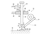
図1に、本発明の一実施形態における接合装置の全体構成を示す。この接合装置は、スポット接合、特に拝み接合(突き合わせ接合)に好適に対応できる据置型の装置構成となっており、直流式の電源回路、制御回路および各種駆動回路等を内蔵したユニット形態の装置本体10と、この装置本体10からの用力の供給と制御の下で電気部品支持体(たとえば回路基板または回路アッセンブリ)S上の被接合材(母材)にアークを用いたろう接(ろう付またはハンダ付)を施す接合ヘッド12と、シールドガスたとえばアルゴンガスの供給源であるガスボンベ14とを有する。
In FIG. 1, the whole structure of the joining apparatus in one Embodiment of this invention is shown. This bonding apparatus has a stationary apparatus configuration that can suitably cope with spot bonding, particularly worship bonding (butt bonding), and is a unit-type apparatus that incorporates a DC power supply circuit, a control circuit, various drive circuits, and the like. Brazing (brazing or brazing or using an arc) on the
接合ヘッド12は、板状のベース16に可動ステージ18とトーチスタンド20を併設し、トーチスタンド20にトーチ22を昇降移動可能に搭載するとともに、トーチスタンド20および可動ステージ18から独立した支持体(図示せず)に溶加材送給装置24を所定の位置および向きで保持させている。
The joining
可動ステージ18は、電気部品支持体Sを水平面内のXY方向で移動させるためのXYステージ26と、電気部品支持体Sを水平面内の方位角方向(θ方向)で移動させるためのθステージ27とを有している。一方、トーチスタンド20は、固定台28の上にたとえばサーボモータを駆動源とする昇降駆動部(図示せず)を内蔵した昇降タワー30を設けている。この昇降タワー30の昇降駆動部に昇降支持軸32を介して直進駆動部材34が結合され、この直進駆動部材34にトーチ22が鉛直方向で一体移動可能に取り付けられている。直進駆動部材34とトーチ22とを連結する機構については、後に詳細に説明する。
The
トーチ22は、水平方向では固定されている。装置本体10より電気ケーブル36を介して送られてくる制御信号の下でXYステージ26およびθステージ27がXY方向の移動動作およびθ方向の移動(回転)動作をそれぞれ行うことにより、ステージ18に載置されている電気部品支持体S上でろう接の対象となる被接合材の被接合部WJをトーチ22の直下に位置決めすることができる。
The
トーチ22は、装置本体10より電気ケーブル内蔵のホース38を介して本実施形態におけるろう接用の電力とシールドガスSGの供給を受けるようになっており、絶縁体たとえば樹脂からなる円筒状のトーチボディ40とこのトーチボディ40の下端(先端)部に取り付けられる円筒状または円錐状のトーチノズル42とを有し、トーチボディ40およびトーチノズル42の中にペンシル形のトーチ電極(タングステン電極棒)44を着脱自在に装着し、トーチノズル42の下端(先端)よりわずかに(通常2〜3mm)トーチ電極44の下端(先端)を突出させている。
The
装置本体10は、ユニット正面に表示器46、操作ボタン48および電源スイッチ50等をタッチパネル形式で配設し、ユニット側面または背面に外部接続端子またはコネクタ類52を配設している。ガスボンベ14よりホース15に送出されるシールドガスSGは、装置本体10およびホース38を経由してトーチ22に供給されるようになっている。
The apparatus
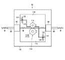
図2に、この実施形態におけるスポット接合の適用可能な被接合材(母材)の一例を示す。図示の例では、たとえば銅からなる2つの細長い棒状または板状の金属部材たとえばバスバーW1,W2を被接合材(母材)とし、両金属部材W1,W2のそれぞれの上端面(頂面)を略面一に揃えてそれぞれの上端部を一体に合わせている。この一体に合わさった金属部材W1,W2の上端部が被接合部WJを形成する。各金属部材W1,W2の他端(図示せず)は、たとえば、電気部品支持体S上に搭載されている電気部品(図示せず)に通じている。あるいは、一方の端子部材W1は電気部品支持体S上に搭載され、他の端子部材W2の他端は別の電気部品支持体(図示せず)上に搭載されている電気部品(図示せず)に通じている。 In FIG. 2, an example of the to-be-joined material (base material) which can apply the spot joining in this embodiment is shown. In the example shown in the figure, for example, two elongated rod-like or plate-like metal members made of copper, for example, bus bars W 1 and W 2 are used as base materials, and upper end surfaces of both metal members W 1 and W 2 ( The top surfaces of the top surfaces are substantially flush with each other, and the upper ends of the top surfaces are integrated together. The upper ends of the metal members W 1 and W 2 combined together form a joined portion WJ. The other end (not shown) of each metal member W 1 , W 2 communicates with an electrical component (not shown) mounted on the electrical component support S, for example. Alternatively, one terminal member W 1 is mounted on an electrical component support S, and the other end of the other terminal member W 2 is mounted on another electrical component support (not shown). (Not shown).
また、図2に示すように、好ましくは被接合部WJを避けて、両金属部材W1,W2に一対の接触子(コンタクト)C1,C2が左右両側から着脱可能に接触する。これらの接触子C1,C2は、電気ケーブル56を介して装置本体10内の電源回路76(図5A〜図5E)の正極に電気的に接続されている。
Further, as shown in FIG. 2, a pair of contacts (contacts) C 1 and C 2 are detachably contacted with both metal members W 1 and W 2 from both the left and right sides, preferably avoiding the joined portion WJ. These contacts C 1 and C 2 are electrically connected to the positive electrode of the power supply circuit 76 (FIGS. 5A to 5E) in the apparatus
溶加材送給装置24は、装置本体10より電気ケーブル62を介して送られてくる制御信号の下で動作し、供給先(アーク)に対してワイヤ状の溶加材Mを突くように送り出し、かつ瞬時に引っ込められるように構成されている。この溶加材送給装置24には、1回の接合動作で供給先に供給されたワイヤ状溶加材Mの量をエンコーダを用いて測定する溶加材供給量測定部110が取り付けられている。溶加材送給装置24および溶加材供給量測定部110の詳細な構成および作用については後に説明する。
The filler
この実施形態では、後述するように常にワイヤ状溶加材Mを外さずに必ずアークACのアーク柱または芯部の中に導入して溶かすことができるので、溶加材送給装置24より被接合部WJに向けて送り出されたワイヤ状溶加材Mの全量がろう接に有効に使用されたものとみなすことができる。 In this embodiment, as will be described later, the wire-like filler material M can always be introduced and melted into the arc column or core of the arc AC without removing the wire-like filler material M. It can be considered that the entire amount of the wire-like filler metal M sent out toward the joint portion WJ is effectively used for brazing.
一例として、母材の金属部材W1,W2がそれぞれ断面2mm×2mmのタフピッチ銅の角棒からなるバスバーである場合、トーチ電極44にはたとえば直径(φ)2.4mmのタングステン棒が用いられ、ワイヤ状溶加材Mにはたとえば直径(φ)0.8mmのりん銅ろうワイヤが用いられる。通常の母材においては、両金属部材W1,W2の接触界面に必ず幾らか(たとえば0.1mm程度)の隙間gが存在する。この実施形態における被接合部WJのろう接では、後述するように、被接合部WJの頂面付近でアーク熱により溶けた溶加材(りん銅ろう)がぬれで拡散して隙間gの中に浸み込むようになっている。
As an example, when the base metal members W 1 and W 2 are each a bus bar made of a tough pitch copper square bar having a cross section of 2 mm × 2 mm, a tungsten bar having a diameter (φ) of 2.4 mm, for example, is used for the
次に、図4A〜図4Fにつき、この実施形態の接合装置において、直進駆動部材34とトーチ22とを連結する機構について説明する。図示のように、板状の直進駆動部材34の貫通孔34aにトーチボディ40が通され、トーチボディ40の上部ないし中間部に固定された鍔状またはフランジ状の連結部材66が直進駆動部材34の上面に載るようにして、トーチボディ40が直進駆動部材34に連結される。
Next, a mechanism for connecting the
かかる構成のトーチ昇降機構においては、トーチ電極44の下端が空中に浮いている間は(図4A)、昇降タワー30が直進駆動部材34を下降させると、連結部材66が直進駆動部材34の上面に載った状態でトーチ22が直進駆動部材34と一体に下降移動する(図4B)。そして、トーチ電極44の下端が母材(W1,W2)の被接合部WJの上面に接触し(図4C)、さらに直進駆動部材34が下降すると、トーチボディ40の連結部66が直進駆動部材34から分離し(図4D)、トーチボディ40は直進駆動部材34から独立して被接合部WJ上で起立するようになる(図4D)。この時、被接合部WJにはトーチ22の自重が加わる。
In the torch elevating mechanism having such a configuration, while the lower end of the
また、トーチ電極44の下端が母材(W1,W2)の被接合部WJに接触している状態(図4E)から、直進駆動部材34を元の高さ位置まで上昇移動させると、その途中でトーチボディ40の連結部材66が直進駆動部材34の上に載ってトーチボディ40も直進駆動部材34と一体に上昇移動するようになっている(図4F)。
Further, when the
この実施形態では、トーチボディ40の連結部材66と直進駆動部材34との間の連結または分離状態を検出するためのセンサ70が備わっている。図示のセンサ70は、垂直リニアスケールからなり、連結部材66の側面に取り付けられている鉛直方向に延びる目盛部72と、この目盛部72を直進駆動部材34の相対的な高さ位置に応じたレベルで光学的に読み取るように直進駆動部材34に取り付けられている目盛読取部74とを有している。目盛読取部74は、反射式の光学センサからなり、電気ケーブル(図示せず)を介して装置本体10内の制御回路に電気的に接続されている。
In this embodiment, the
このセンサ70においては、トーチボディ40の連結部材66が直進駆動部材34の上に載っている限り、直進駆動部材34が任意の高さ位置で昇降移動しても目盛読取部74の出力信号(読取値)は一定値を保つ。しかし、直進駆動部材34がトーチボディ40の連結部材66から分離すると、目盛部72と目盛読取部74との相対位置が変化し、目盛読取部74の出力信号(読取値)が変化する。装置本体10の中に置かれている制御部は、目盛読取部74からの出力信号に基づいて直進駆動部材34とトーチボディ40との相対的な位置関係を監視できるとともに、直進駆動部材34が往動(下降移動)する途中でトーチ電極44の下端が母材(W1,W2)の被接合部WJに接触したときは、そのことを検出できる。なお、このような目盛を用いる光学式のセンサに代えて、近接センサ等の他の方式のセンサを用いることも可能である。
In this
次に、図3、図4A〜図4Fおよび図5A〜図5Eを参照して、この実施形態における接合装置の動作およびろう接方法(スポット接合方法)を説明する。 Next, the operation of the bonding apparatus and the brazing method (spot bonding method) in this embodiment will be described with reference to FIGS. 3, 4A to 4F, and 5A to 5E.
先ず、タフピッチ銅の母材(W1,W2)を支持する電気部品支持体Sがステージ18上に載置されている状態で、XYステージ26およびθステージ27が上記のように装置本体10内の制御部による制御の下で水平面内の位置合わせを行う。この位置合わせ動作により、母材(W1,W2)の被接合部WJ上に予め設定された位置、つまり通電開始のためにトーチ電極44の下端が接触すべき位置(以下、「通電開始位置」と称する。)Qがトーチ電極44の真下に位置するようになる。図示の例のようなスポット接合(拝み接合)の場合は、被接合部WJの頂面上で隙間gまたはその付近の箇所に通電開始位置Qを設定するのが好ましい。
First, in the state where the electrical component support S supporting the base material (W 1 , W 2 ) of tough pitch copper is placed on the
通常、電気部品支持体S上で接合対象となっている全ての被接合部WJにXY座標が割り当てられるので、オープンループ制御の位置合わせ動作を行える。もっとも、モニタカメラ等を用いてフィードバック制御の位置合わせ動作を行うことも可能である。 Usually, since the XY coordinates are assigned to all the joined parts WJ to be joined on the electrical component support S, the alignment operation of the open loop control can be performed. However, it is also possible to perform a feedback control alignment operation using a monitor camera or the like.
上記のようにしてステージ18上で母材(W1,W2)の被接合部WJがトーチ電極44の真下に位置決めされると、溶加材送給装置24と被接合部WJとの間でも位置合わせが完了する。すなわち、溶加材送給装置24と被接合部WJとの間では、最後段スリーブ90の先端またはワイヤ状溶加材Mの先端が母材(W1,W2)の被接合部WJ上の通電開始位置Qを斜め上方から指すような位置関係になる(図5A)。
When the bonded portion WJ of the base material (W 1 , W 2 ) is positioned directly below the
上記のような水平面内の位置合わせとは別に、高さ方向においても装置本体10内の制御部により昇降タワー30を通じてトーチ22のトーチスタート位置が適当な高さ位置に調整される。ただし、同一種類の複数の被接合部に対して同一条件のろう付を続けて行う場合は、各回のろう付の終了後にトーチ22を一定のトーチスタート位置に戻すことによって、次回のろう付けのための初期高さ位置調整を省くこともできる。
Apart from the alignment in the horizontal plane as described above, the torch start position of the
上記のような位置合わせないし初期高さ位置の調整が済んでいる状態(図4A)から、装置本体10内の制御部による制御の下で、ステージ18上の母材(W1,W2)に対するろう接が接合ヘッド12で実行される。図3のフローチャートは、1回のスポット接合が行われるときの制御部の制御手順を示す。制御部は、マイクロコンピュータ、メモリおよび各種インタフェース等を含んでおり、メモリに蓄積または格納した所定のプログラムにしたがって装置内の各部の動作および全体のシーケンスを制御する。制御部は、スポット接合の開始に先立ち、図6の溶加材供給量測定部110のエンコーダ出力値LEi-1をメモリまたはレジスト等にセット(保存)しておく。通常、スポット接合開始時のエンコーダ出力値LEi-1は、前回のスポット接合の終了後にワイヤ状溶加材Mの先端を所定のワイヤスタート位置PSに着かせるための後述する溶加材先端位置調整が完了した時のエンコーダ出力値に対応している。
The base material (W 1 , W 2 ) on the
先ず、制御部は、昇降タワー30の昇降駆動部を作動させて、直進駆動部材34の下降移動を開始する(ステップS1)。トーチ電極44の下端は空中に浮いているので(図4A)、直進駆動部材34の下降移動が開始されると、連結部材66が直進駆動部材34の上面に載った状態でトーチ22も直進駆動部材34と一体に下降移動する(図4B)。
First, the control unit operates the elevating drive unit of the elevating
そして、トーチ電極44の下端が被接合部WJに通電開始位置Q(または少しずれてその近傍)で接触すると(ステップS2)、トーチ22の下降移動がそこで終了する(図4C)。その直後に、直進駆動部材34がトーチボディ40の連結部材66から分離すると(図4D)、制御部がセンサ70の出力信号に応答して直進駆動部材34の下降移動を止める(ステップS3)。
When the lower end of the
なお、制御部は、トーチ22の下降移動の途中で、あるいは下降移動の終了直後に、シールドガスSGの供給を開始する。シールドガスSGは、ボンベ14から装置本体10およびホース38を介してトーチ22に供給される。トーチ22は、トーチボディ40の上部にシールドガスSGを導入し、導入したシールドガスSGをトーチノズル42の開口から所定の流量(たとえば5リットル/分)で噴出する。
Note that the control unit starts supplying the shield gas SG in the middle of the downward movement of the
こうしてトーチ電極44の下端が被接合部WJ上の通電開始位置Q(またはその近傍)に接触している状態の下で、制御部は通電を開始する(ステップS4)。すなわち、装置本体10内で定電流源からなる直流電源回路76のスイッチSWをそれまでのオフ状態からオン状態に切り換える。そうすると、直流電源回路76の正極→オン状態のスイッチSW→電気ケーブル56→接触子C1,C2→被接合部WJ→トーチ電極44→ホース38内の電気ケーブル39→直流電源回路76の負極の経路または閉回路78内で、一定の直流電流iが流れる(図5C)。
Thus, the control unit starts energization under the state where the lower end of the
この直流電流iの電流値は、通電開始から終了まで一定値に保たれてもよく、あるいは途中で段階的または連続的に切り換えられてもよい。通電時間を通じて一定値に保つ場合は、トーチ電極44の下端を被接合部WJから離してアークを発生させた時に、融点640℃のワイヤ状溶加材(りん銅ろう)Mは速やかに溶けつつも融点1000℃以上の被接合部(タフピッチ銅)WJは全くまたは殆ど溶けないようなアーク熱が得られる電流値IM(たとえば70〜90A)に設定される。
The current value of the direct current i may be kept constant from the start to the end of energization, or may be switched stepwise or continuously in the middle. When maintaining a constant value throughout the energization time, when the arc is generated by separating the lower end of the
あるいは、この接触状態下の初期通電時において、電流iの電流値をろう接に適した上記の値IMより一段と低い値ISに制御してもよい。すなわち、トーチ電極44の寿命を延ばすには、トーチ電極44の先端が被接合部WJから離れた瞬間にアーク放電を出来るだけ弱く発生させるのが好ましい。一方で、トーチ電極44の先端を被接合部WJから引き離して開始されるろう接のぬれ性を良くするには、この段階(接触状態下)の通電において被接合部WJに適度のジュール熱を発生させて予備加熱しておくのが好ましい。この実施形態では、これら両面の観点から、上記閉回路78内で流す電流iの通電開始時の電流値ISをたとえば10〜20Aの範囲に制御する。
Alternatively, at the time of initial energization under this contact state, the current value of the current i may be controlled to a value I S that is much lower than the value I M suitable for brazing. That is, in order to extend the life of the
制御部は、通電開始から所定時間T1が経過すると(ステップS5)、直進駆動部材34を幾らか上昇移動させて、トーチ電極44の下端を被接合部WJから設定離間距離(たとえば3mm)だけ上方に引き離し(ステップS6)、その高さ位置で静止させる。そして、このトーチ電極44の引き離しと同時に、または引き離しが完了した後に、制御部が電源回路76を制御して、上記閉回路78内で流す電流iの電流値をそれまでの初期電流値ISよりも一段と大きいろう接またはスポット溶接用の正規電流値IMに切り換える(ステップS7)。
When the predetermined time T 1 has elapsed from the start of energization (step S 5 ), the control unit moves the
こうしてトーチ電極44の下端が被接合部WJから離間し、かつ上記閉回路78内で正規電流値IMの電流(アーク電流)iが流れることにより、融点1000℃以上の被接合部(タフピッチ銅)WJを全くまたは殆ど溶かさずに融点640℃のワイヤ状溶加材(りん銅ろう)Mを速やかに溶かすことができるアークACが、トーチ電極44と被接合部WJとの間の空間ギャップに、特にトーチ電極44の下端と被接合部WJ上の通電開始位置Qとの間の空間ギャップに生成される。
In this way, the lower end of the
そして、トーチ電極44の先端を被接合部WJから引き離してから、あるいは上記閉回路78内の電流iの電流値を正規値IMに切り換えてから所定の遅延時間T2が経過すると(ステップS8)、このタイミングで制御部は溶加材送給装置24を通じてアークACの中へのワイヤ状溶加材Mの供給を開始する(ステップS9)。
Then, when a predetermined delay time T 2 elapses after the tip of the
この遅延時間T2は、ぬれ性を良くするための最適時間や母材に与える影響等を考慮して決められ、通常は0.1〜0.5秒の範囲に選ばれる。また、この遅延時間T2の経過時にジャスト・イン・タイムでワイヤ状溶加材Mの先端がアークACのアーク柱の中に突入するように、溶加材送給装置24の動作を開始するタイミングを若干早めてもよい。
This delay time T 2 is determined in consideration of the optimum time for improving the wettability and the influence on the base material, and is usually selected in the range of 0.1 to 0.5 seconds. In addition, the operation of the filler
この実施形態では、ワイヤ状溶加材Mの先端が被接合部WJ上の通電開始位置Qをめがけて斜め上方から送られるため、ワイヤ状溶加材Mが確実にアークACのアーク柱の下端部に導入され、その導入位置でアーク熱を浴びて速やかに溶ける。そして、溶けた溶加材<M>は、ねれで周囲に拡がり、被接合部WJの隙間gの中または内奥に浸み込む(図5D)。 In this embodiment, since the tip of the wire-like filler material M is sent from obliquely upward toward the energization start position Q on the joined portion WJ, the wire-like filler material M is surely connected to the lower end of the arc column of the arc AC. It is introduced into the part and melts quickly by receiving arc heat at the introduction position. Then, the melted filler material <M> spreads to the periphery due to the slack, and penetrates into the gap g of the bonded portion WJ or inside (see FIG. 5D).
一方で、溶加材送給装置24によりワイヤ状溶加材MがアークACの中に送られると、ワイヤ状溶加材Mの移動(前進移動)に応じて溶加材供給量測定部110のエンコーダ出力値Eiが変化する。制御部は、溶加材供給量測定部110からのエンコーダ出力値Eiを遂次取り込んで更新する。
On the other hand, when the wire-like melt material M is fed into the arc AC by the melt
そして、制御部は、エンコーダ出力値Eiを監視し、ワイヤ状溶加材Mの供給を開始してからエンコーダ出力値Eiのインクリメント値ΔEが設定値ΔESに達した時点で、設定量のワイヤ状溶加材MがアークACの中に供給されたものと判断し(ステップS10)、直ちに溶加材送給装置24を制御してワイヤ状溶加材MをアークACから退避させ(ステップS11)、次いで電源回路76のスイッチSWをオフ状態に切り換えて通電を止める(ステップS12)。直後にシールドガスSGの供給も止める。なお、ワイヤ状溶加材MをアークACから退避させるときの後退移動速度は、供給時の前進移動速度(たとえば10〜80mm/sec)より数倍以上高い値(たとえば200mm/sec)に設定される。後退する時の移動距離はたとえば3mmに設定される。
Then, the control unit monitors the encoder output values E i, when the increment Delta] E of the wire-shaped filler M encoder output values E i from the start of the supply of has reached the set value Delta] E S, the set amount The wire-like filler metal M is determined to have been supplied into the arc AC (step S 10 ), and the filler-
ワイヤ状溶加材MがアークACから退避すると、その瞬間に被接合部WJへの溶加材の供給が停止する。また、通電が止まると、その瞬間にアークは消滅する。アークが消滅すると、被接合部WJの隙間gの中およびその周囲に拡散していた溶融状態(液状)の溶加材<M>が大気中の自然冷却によって直ぐに凝固して固体金属または合金[M]となる。こうして、母材(W1,W2)の被接合部WJにろう接の拝み接合(継手)が形成される。 When the wire-like filler material M is retracted from the arc AC, the supply of the filler material to the welded portion WJ is stopped at that moment. When the energization stops, the arc disappears at that moment. When the arc disappears, the melted (liquid) filler material <M> diffused in and around the gap g of the joint WJ is immediately solidified by natural cooling in the atmosphere and solid metal or alloy [ M]. In this way, brazing welding joints (joints) are formed at the joints WJ of the base materials (W 1 , W 2 ).
この後、制御部は、昇降タワー30の昇降駆動部を通じて直進駆動部材34を上昇移動させて、トーチ22をトーチスタート位置に戻す(ステップS13)。
Thereafter, the control unit moves the
上述したように、この実施形態においては、母材(W1,W2)の被接合部WJにトーチ電極44の先端を接触させた状態で、トーチ電極44の周囲にシールドガスSCを供給しながら、トーチ電極44と被接合部WJとの間で通電を開始する。そして、シールドガスSCの供給と通電を継続しながら、トーチ電極44の先端を被接合部WJから離して、トーチ電極44と被接合部WJとの間で母材(W1,W2)を全くまたは殆ど溶かさずに溶加材Mを速やかに溶かすことができるアークACを発生させる。そして、少し遅れてこのアークACの中にワイヤ状の溶加材Mを供給して、溶加材MをアークACの熱で溶かし、溶けた溶加材<M>をぬれで拡散させて被接合部WJの隙間gに浸み込ませる。そして、一定時間経過後に(または、ワイヤ状溶加材Mの送出量または供給量が設定値に達したタイミングで)、溶加材MをアークACから退避させ、次いでアークACを消滅させて、被接合部WJの隙間gおよびその回りに拡散していた溶融状態(液状)の溶加材<M>を凝固させる。
As described above, in this embodiment, the shield gas SC is supplied around the
このように、この実施形態では、トーチ電極44と母材(W1,W2)の被接合部WJとの間に発生させるアークACを、被接合部WJの溶融(アーク溶接)にではなく、専ら可溶材Mの溶融に用いる。これによって、被接合部WJにはろう接による金属接合(継手)が得られる。したがって、たとえば、母材(W1,W2)の材質がタフピッチ銅であっても、アーク溶接で見られるようなブローホールが原理的に発生することはない。
Thus, in this embodiment, the arc AC generated between the
しかも、タッチスタート方式でアークACを発生させ、被接合部WJのトーチ電極44の先端が接触していた位置(通電開始位置Q)をめがけてワイヤ状の溶加材Mを送るので、溶加材Mを外さずに確実にアークACのアーク柱または芯部の中に導入して最も効率よく溶かすことができる。
In addition, since the arc AC is generated by the touch start method, the wire-like filler material M is fed toward the position (energization start position Q) where the tip of the
そして、この実施形態では、後述する溶加材供給量測定部110により、今回のスポット接合でトーチ電極44と被接合部WJ間のアークに供給されたワイヤ状溶加材Mの量(長さ)が測定され、1回のスポット接合におけるワイヤ状溶加材Mの供給量が常に設定通りに管理されるとともに、その測定値つまり溶加材供給量測定値が装置本体10の表示器46上の表示出力または他の型式のデータ出力を通じてユーザに提供される。このタイプのスポット接合において、アークに与えられたワイヤ状溶加材Mの供給量は、被接合部WJ上で溶融した溶加材<M>の量に比例し、ひいては溶融溶加材<M>が凝固して出来た合金[M]の量に比例し、ろう接加工の品質(接合強度や仕上がり等)を大きく左右する。ユーザは、提示された溶加材供給量測定値を当該スポット接合の品質を保証するバロメータ(品質管理情報)として活用することができる。
In this embodiment, the amount (length) of the wire-like filler material M supplied to the arc between the
さらに、ろう接によって形成された金属接合は、仮に接合不良であったとしても、取り戻し(リカバリー)や遣り直しが利くので、歩留まりの面でも有利である。また、アーク溶接と比較して、トーチ電極と母材との間に発生させるアークのアーク熱は格段に弱いので、つまりアーク電流が格段(約1/2程度)に小さいので、周囲に与える熱影響が少なく、消費電力の節約を図ることもできる。
[溶加材供給量測定部の構成]
Furthermore, metal bonding formed by brazing is advantageous in terms of yield because it is easy to recover (recover) or redo even if the bonding is defective. Compared with arc welding, the arc heat generated between the torch electrode and the base metal is much weaker, that is, the arc current is much smaller (about 1/2). It has little effect and can save power consumption.
[Configuration of the filler supply amount measurement unit]
以下、図6および図7を参照して、この実施形態における溶加材送給装置24および溶加材供給量測定部110の構成を説明する。
Hereinafter, with reference to FIG. 6 and FIG. 7, the structure of the filler
図6に示すように、溶加材送給装置24は、ワイヤ状溶加材Mを円滑に送り出せるように巻き付けているワイヤリール80、このワイヤリール80からワイヤ状溶加材Mを所望の速度で送り出すための送給ローラ82および押さえローラ84、送給ローラ82を回転駆動するための逆送り機能付きサーボモータ(図示せず)、ワイヤ状溶加材Mをワイヤ移動路上の所々で直線状に規制または案内するためのストレイナ86および複数のスリーブ88,90,・・を有している。ここで、ワイヤ移動路上の下流に位置するスリーブ88,90は、トーチ22および被接合部WJの近くに配置される溶加材送給ヘッド92に取り付けられる。
As shown in FIG. 6, the filler
溶加材送給ヘッド92は、厚板状のベース部材94に、溶加材送給装置24の溶加材案内部またはスリーブ88,90をそれぞれスリーブホルダ96,98を介して取り付けるとともに、溶加材供給量測定部110の主要な構成要素であるロータリエンコーダ112および溶加材先端位置調整部115を取り付けている。
The filler
ロータリエンコーダ112は、ベース部材94の上に取り付けられている。このロータリエンコーダ112は、インクリメンタル形またはアブソリュート形のいずれであってもよく、ワイヤ状溶加材Mの移動に追従して回転するプーリまたはローラ112aと、このローラ112aの回転量または回転角度をエンコーダ本体112b内で電気的なパルス信号に変換するエンコーダ出力信号生成部(図示せず)とを有している。
The
より詳しくは、図7に示すように、ロータリエンコーダ112は、ベース部材94の上で固定された支持板116側に配置されている。一方、ロータリエンコーダ112のローラ112aと対向して配置される押さえローラ114が、ベース部材94の上で固定支持板116と並んで可動に配置された可動支持板118に取り付けられている。両支持板116,118の間にばね支持棒120,122を介して張設された複数個の引っ張りコイルばね124により、押さえローラ114がワイヤ状溶加材Mを挟んでローラ112aに弾力的に押し付けられる。これにより、ワイヤ状溶加材Mは、ロータリエンコーダ112のローラ112aの外周面と押さえローラ114の外周面との間を大きな動摩擦力を受けながら殆どすべらずに移動することができる。
More specifically, as shown in FIG. 7, the
このように、ロータリエンコーダ112の回転方向および回転量は、ワイヤ状溶加材Mの移動方向および移動量に対応または比例する。こうして、ワイヤ状溶加材Mの移動方向および移動量を表わすエンコーダ出力値がロータリエンコーダ112より得られるようになっている。
Thus, the rotation direction and the rotation amount of the
溶加材先端位置調整部115は、ベース部材94の下面に取り付けられている直動式のアクチエータたとえばエアシリンダ126と、溶加材送給装置24の最後段スリーブ90の先端付近に配置される位置センサ128と、エアシリンダ126の駆動軸126aと位置センサ128とを繋ぐアーム状またはフレーム状のセンサ支持部130とを有している。エアシリンダ126を作動させて、駆動軸126aを前進または後退させることで、ワイヤ移動路上でスリーブ90の先端より後方に設定されている待機位置POと、前方に設定されているワイヤスタート位置PSとの間で位置センサ128の位置を切り換えられるようになっている。位置センサ128は、溶加材Mの先端位置が直近の監視点つまりワイヤスタート位置PSに一致または近似している否かをたとえば光学的に検知または判別できるように構成されている。
The filler material tip
なお、この実施形態において、装置本体10内の制御部は、ロータリエンコーダ112からのエンコーダ出力値に基づいて溶加材供給量測定値を演算する機能や、溶加材先端位置調整部115においてワイヤ状溶加材Mの先端をワイヤスタート位置PSに着かせるための制御機能など、溶加材供給量測定部110における演算機能または制御機能の一切を担っている。
[溶加材供給量測定部の作用(溶加材先端位置調整)]
In this embodiment, the control unit in the apparatus
[Operation of the filler supply amount measuring unit (adjustment of the filler material tip position)]
次に、図8および図9を参照して、この実施形態における溶加材供給量測定部110の作用、特に溶加材先端位置調整の手順を説明する。図8に、溶加材先端位置調整における制御部の制御または演算手順を示す。図9に、溶加材先端位置調整の各段階を模式的に示す。
Next, with reference to FIG. 8 and FIG. 9, the operation of the filler material supply
この実施形態では、1回のスポット溶接が終了した後に、制御部の制御の下で溶加材先端位置調整部115によりワイヤ状溶加材Mの先端をワイヤスタート位置PSに着かせるための溶加材先端位置調整が行われる。
In this embodiment, once after the spot welding is completed, the filler material tip
上記のように、ワイヤ状溶加材MをアークACから退避させるときの後退移動距離は一定値に制御される。このため、図9の(a)に示すように、スポット溶接の終了後のワイヤ状溶加材Mの先端はスリーブ90の先端より幾らか前方に位置している。もっとも、加工条件が同じでもスポット溶接毎にアークACの強度や拡がりは微妙に異なり、ワイヤ状溶加材Mの溶融速度が微妙に異なるので、スポット溶接終了後のワイヤ状溶加材Mの先端位置は厳密には不定である。
As described above, the backward movement distance when the wire-shaped filler metal M is retracted from the arc AC is controlled to a constant value. For this reason, as shown in FIG. 9A, the tip of the wire-like filler material M after the end of spot welding is located somewhat forward of the tip of the
先ず、制御部は、スポット溶接終了後の停止しているロータリエンコーダ112の出力値Eiを読み取る(ステップS20)。次いで、制御部は、エアシリンダ126を作動させ、図9の(b)に示すように、それまで待機位置POで待機していた位置センサ128をワイヤスタート位置PSまで移動させる(ステップS21)。
First, the control unit reads the output value E i of the
この後、制御部は、図9の(c),(d)に示すように、溶加材送給装置24を通じてワイヤスタート位置PS付近でワイヤ状溶加材Mを可変の距離(δp)だけ前方に送り、または後方に戻す動作(ステップS22)と、この調整移動後のエンコーダ112の出力値Eiを読み取って更新する処理(ステップS23)と、位置センサ128を通じて調整移動後のワイヤ状溶加材Mの先端位置がワイヤスタート位置PSに一致または近似しているか否かを判定する処理(ステップS24)とを適宜繰り返して、ワイヤ状溶加材Mの先端位置をワイヤスタート位置PSに徐々に近づけていく。そして、図9の(e)に示すように、ワイヤ状溶加材Mの先端位置がワイヤスタート位置PSに一致または近似したときは、そこでワイヤ状溶加材Mの調整移動(送り/戻し)を終了し、このときのエンコーダ112の出力値Eiを最終出力値LEiとして読み取る(ステップS25)。
Thereafter, the control unit, of FIG. 9 (c), (d), the distance the wire-shaped filler metal M variable through
次いで、制御部は、上記のような溶加材先端位置調整によって決定されたロータリエンコーダ112の最終出力値LEiと、今回のスポット溶接の開始前にメモリまたはレジスタにセットしていたエンコーダ出力値LEi-1との差分(LEi−LEi-1)を演算し、今回のワイヤ供給量測定値LMiとする(ステップS26)。つまり、この差分(LEi−LEi-1)は今回のスポット溶接の前後でワイヤ状溶加材Mの先端位置が同一(ワイヤスタート位置PS)に在るときのエンコーダ出力値LEi-1,LEiの差分であるから、今回のワイヤ供給量測定値LMiに相当する。制御部は、このワイヤ供給量測定値LMiをメモリに記憶(保存)するとともに、表示器46上に表示する。
Next, the control unit determines the final output value LE i of the
上述したように、この実施形態においては、今回のスポット接合でトーチ電極44と被接合部WJ間のアークに供給されたワイヤ状溶加材Mの量(長さ)をロータリエンコーダ112を通じて測定し、その溶加材供給量測定値のモニタ情報をユーザに提供するようにしたので、ユーザは、提示された溶加材供給量測定値を当該スポット接合の品質を保証するバロメータ(品質管理情報)として有効活用することができる。
As described above, in this embodiment, the amount (length) of the wire-like filler metal M supplied to the arc between the
特に、この実施形態においては、溶加材送給装置24の溶加材送給ヘッド92に溶加材供給量測定部110のロータリエンコーダ112を設け、ワイヤ状溶加材Mの先端の近くでワイヤ状溶加材Mの移動量ないし供給量を測定するので、ワイヤ移動路上の上流側でワイヤ状溶加材Mが撓んでも溶加材供給量測定部110はその影響を受けずに今回のスポット接合におけるワイヤ状溶加材Mの供給量または消費量を精確に測定することができる。
[他の実施形態又は変形例]
In particular, in this embodiment, a
[Other Embodiments or Modifications]
以上、本発明の好適な実施形態について説明したが、上述した実施形態は本発明を限定するものではない。当業者にあっては、具体的な実施態様において本発明の技術思想および技術範囲から逸脱せずに種々の変形・変更を加えることが可能である。 As mentioned above, although preferred embodiment of this invention was described, embodiment mentioned above does not limit this invention. Those skilled in the art can make various modifications and changes in specific embodiments without departing from the technical idea and technical scope of the present invention.
たとえば、溶加材供給量測定部110のロータリエンコーダ112を溶加材送給装置24の送給ローラ82に取り付ける構成も可能である。また、送給ローラ82に代えて、溶加材供給量測定部110のロータリエンコーダ112にサーボモータを付けて溶加材送りの駆動を行う構成も可能である。これらの場合でも、溶加材先端位置調整部115は、上記実施形態と同様に溶加材送給装置24の溶加材送給ヘッド92に取り付けられるのが好ましい。
For example, a configuration in which the
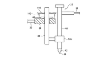
また、上述した実施形態では、トーチ電極44の下端が母材(W1,W2)の被接合部WJの上面に接触してから直進駆動部材34がさらに下降すると、被接合部WJにはトーチ22の自重が加わるようになっていた。別の実施例(変形例)として、図10に示すように、直進駆動部材34とトーチボディ40の一部(たとえばトーチボディ40に固定された鍔状のばね受け部140)との間に、直進駆動部材34の移動する方向で弾性変形可能なばね部材たとえばコイルばね142を設けることも可能である。この場合、コイルばね142に圧縮コイルばねを用いることで、トーチ電極44が被接合部WJに接触したときに被接合部WJの受ける荷重をトーチボディ40の自重より任意に軽くすることができる。母材(W1,W2)が小型精密電子部品の端子部材である場合に有利な形態である。あるいは、コイルばね142に引っ張りコイルばねを用いることで、トーチ電極44が被溶接部WJに接触したときに被溶接部WJの受ける荷重をトーチボディ40の自重より任意に重くすることもできる。なお、ばね受け部140の位置を調整する機構(図示せず)を備えることで、コイルばね142のばね力を調整することもできる。
In the above-described embodiment, when the
このように直進駆動部材34にコイルばね142を介してトーチボディ40を取り付ける構成においては、直進駆動部材34を斜め方向または水平方向で直進移動させ、トーチ電極44を同方向に直進移動させることも可能である。
In the configuration in which the
上述した実施形態における直進駆動部材34の板状の形態は一例であり、直進駆動部材34は任意の形状の板体、ブロック、筒体、筺体の構造を採ることが可能である。同様に、連結部材66も任意の形態を採ることができる。
The plate-like form of the
また、上述した実施形態では、直進駆動部材34にトーチ22を直接取り付けた。しかし、図11に示すように、直進駆動部材34にたとえば昇降棒のような直進可動部材144を鉛直方向で一体移動可能かつ分離可能に取り付け、この直進可動部材144に結合されたホルダ146にトーチ22を着脱可能に取り付ける構成も可能である。
In the above-described embodiment, the
また、上述した実施形態では、2つの金属部材W1,W2の先端部分を合わせてろう接する拝み接合を行った。しかし、図示省略するが、2つの金属部材W1,W2の先端または側面を突き合わせてろう接する突き合わせ接合も可能であり、 さらには、2つの金属部材W1,W2を重ね合わせてろう接する重ね合わせの接合も可能である。 Further, in the above-described embodiment, worship joining is performed in which the tip portions of the two metal members W 1 and W 2 are joined together by brazing. However, although not shown in the drawing, it is possible to perform butt joining in which the tips or side surfaces of the two metal members W 1 and W 2 are butted and brazed, and furthermore, the two metal members W 1 and W 2 are overlapped and brazed. Superposition joining is also possible.
なお、アークACの中にワイヤ状の溶加材Mを供給するときは、被溶接部WJ上の通電開始位置Qをめざして溶加材Mを送るのが最も好ましい。しかし、通電開始位置Qの直上、つまりトーチ電極44の先端と通電開始位置Qとの間のギャップをめがけて溶加材Mを送ることも可能である。溶加材Mの形体は任意であり、ワイヤに限定されず、たとえば棒や板体であってもよい。
In addition, when supplying the wire-like melt material M in the arc AC, it is most preferable to send the melt material M aiming at the energization start position Q on the welded portion WJ. However, it is also possible to feed the filler material M directly over the energization start position Q, that is, through the gap between the tip of the
上記実施形態における接合装置は据置型であったが、ロボットに搭載する形態も可能である。その場合は、直進駆動部材34または昇降支持軸32をロボットアームに結合すればよい。同様に、溶加材送給装置24も、トーチ22と一緒に同一のロボットに搭載してもよく、あるいは別のロボットに搭載することもできる。
Although the joining apparatus in the above embodiment is a stationary type, a form mounted on a robot is also possible. In that case, the
上記実施形態における接合装置は、接合ヘッド12のステージ18に自動位置合わせ機構(XYステージ25、θステージ26)を備えた。しかし、ステージ18を手動式の可動ステージに構成することや、あるいは固定式のステージ18上でワークまたは電気部品支持体Sの位置合わせを手動で行うことも可能である。
The bonding apparatus in the embodiment includes the automatic alignment mechanism (XY stage 25, θ stage 26) on the
被接合部WJにおいて、金属部材W1,W2の材質は銅または銅合金に限定されず、たとえばアルミニウムまたはアルミニウム金合や真鍮等の導体であってもよく、端子部材W1の材質と端子部材W2の材質が異なっていてもよい。また、金属部材W1,W2の形状も任意でよく、たとえば断面が矩形の棒体または板体に限らず断面が円形の棒体または板体であってもよい。 In the joined portion WJ, the material of the metal members W 1 and W 2 is not limited to copper or a copper alloy, and may be a conductor such as aluminum, aluminum alloy, or brass, and the material and terminals of the terminal member W 1 the material of the member W 2 may be different. Further, the shape of the metal members W 1 and W 2 may be arbitrary, and for example, the metal member W 1 or W 2 is not limited to a rod or plate having a rectangular cross section, and may be a rod or plate having a circular cross section.
また、スポット溶接の最中に、温度センサたとえば放射温度計を用いて被接合部WJの温度をモニタし、モニタ温度を一定の値または一定の範囲に制御するように、制御部が電源回路76を通じて電流iの初期電流値ISを可変に制御することも可能である。
Further, during spot welding, the controller controls the
より詳細には、制御部は、溶加材送給装置24を通じてワイヤ状溶加材MをアークACの中に供給しながら、温度センサを通じて被接合部WJの温度を監視して、被接合部WJの温度が溶加材Mの融点よりも高くて母材(W1,W2)の融点を超えないように、アーク電流iを制御する。より具体的には、被接合部WJの測定温度が溶加材Mの融点より高くて母材(W1,W2)の融点より低い所定の基準温度(たとえば750℃)に一致または近似するように、アーク電流iの電流値IMを制御する。たとえば、被接合部WJの測定温度が基準温度より下がったときはアーク電流iの電流値IMを100A程度に上げ、被接合部WJの測定温度が基準温度を超えた時はアーク電流iの電流値IMをたとえば10A程度に下げるような制御を繰り返す。
More specifically, the control unit monitors the temperature of the welded portion WJ through the temperature sensor while supplying the wire-like melted material M into the arc AC through the melt
このように被接合部WJの温度を制御し、ひいてはワイヤ状溶加材Mを溶かす温度を制御することによって、アークACのアーク熱を利用して行われるろう接の効率性と信頼性および再現性を向上させることができる。 By controlling the temperature of the welded portion WJ and thus the temperature at which the wire filler metal M is melted, the efficiency, reliability and reproduction of brazing performed using the arc heat of the arc AC are controlled. Can be improved.
温度センサしては、放射温度計以外にも、たとえば熱電対も使用可能である。その場合、熱電対を被接合部WJに直接取り付けるよりも、コンタクトC1,C2(図2)取り付ける方が好ましい。 In addition to the radiation thermometer, for example, a thermocouple can be used as the temperature sensor. In that case, it is preferable to attach the contacts C 1 and C 2 (FIG. 2) rather than directly attaching the thermocouple to the bonded portion WJ.
10 装置本体
12 接合ヘッド
18 可動ステージ
22 トーチ
24 溶加材送給装置
30 昇降タワー
34 直進駆動部材
40 トーチボディ
44 トーチ電極
110 溶加材供給量測定部
112 ロータリエンコーダ
115 溶加材先端位置調整部
128 位置センサ
DESCRIPTION OF
Claims (7)
非消耗型のトーチ電極を有し、前記トーチ電極と前記被接合部との間に前記被接合部を全くまたは殆ど溶かさないアークを発生させるアーク発生部と、
前記アークに向けてワイヤ状または棒状の溶加材を送り、所定量の前記溶加材を供給した後に前記溶加材を前記アークから退避させる溶加材送給部と、
1回の接合動作で前記溶加材送給部により前記アークに供給された前記溶加材の量を測定する溶加材供給量測定部と
を有し、
前記溶加材供給量測定部は、前記溶加材送給部において前記溶加材が前進または後退したときの移動量を遂次測定するためのエンコーダと、1回の接合動作の開始前および終了後に前記溶加材の先端を所定のワイヤスタート位置に着かせるための溶加材先端位置調整部と、前記接合動作の開始前に前記溶加材の先端が前記ワイヤスタート位置に着いた時に前記エンコーダより得られた第1のエンコーダ出力値と、前記接合動作の終了後に前記溶加材の先端が前記ワイヤスタート位置に着いた時に前記エンコーダより得られた第2のエンコーダ出力値とから前記アークに供給された前記溶加材の量の測定値を求める演算部とを有し、前記溶加材の先端を目印にして前記溶加材の供給量を測定する、
接合装置。 A joining device for joining the joined parts of the first and second metal members,
An arc generating part that has a non-consumable torch electrode and generates an arc that melts the to-be-joined part at all or hardly between the torch electrode and the to-be-joined part;
Sending a wire-like or rod-like filler material toward the arc, and supplying a predetermined amount of the filler material, and then feeding the filler material away from the arc;
A filler material supply amount measuring unit for measuring the amount of said filler material supplied to the arc possess by the filler material feeder by bonding a single operation,
The filler material supply amount measuring unit includes an encoder for successively measuring the amount of movement when the filler material advances or retracts in the filler material supply unit, and before the start of one joining operation and A filler material tip position adjusting portion for causing the tip of the filler material to reach a predetermined wire start position after completion, and when the tip of the filler material arrives at the wire start position before the start of the joining operation From the first encoder output value obtained from the encoder and the second encoder output value obtained from the encoder when the tip of the filler material arrives at the wire start position after completion of the joining operation. An arithmetic unit for obtaining a measurement value of the amount of the filler material supplied to the arc, and measuring the supply amount of the filler material with the tip of the filler material as a mark,
Joining device.
前記移動機構は、前記被接合部に対して前記トーチボディを前記トーチ電極の軸方向と平行に直進移動可能な直進駆動部材を備え、前記トーチ電極を前記被接合部から遠ざけるための第1の位置と、前記トーチ電極の先端を前記被接合部に接触させるための第2の位置と、前記トーチ電極の先端をアークの生成に適した所定の距離だけ前記被接合部から離すための第3の位置との間で、前記直進駆動部材を直進移動させる、
請求項1に記載の接合装置。 The arc generator includes a torch body that detachably mounts and holds the torch electrode, a power source for flowing a current in a closed circuit including the torch electrode and the bonded portion, and the bonded portion A moving mechanism that relatively moves the torch body, and starts energization in the closed circuit in a state where the tip of the torch electrode is in contact with the joined portion, and energization in the closed circuit The arc is generated between the torch electrode and the bonded portion by separating the tip of the torch electrode from the bonded portion while continuing ,
The moving mechanism includes a rectilinear drive member capable of linearly moving the torch body in parallel with the axial direction of the torch electrode with respect to the bonded portion, and a first mechanism for moving the torch electrode away from the bonded portion. A second position for bringing the tip of the torch electrode into contact with the joined portion, and a third position for separating the tip of the torch electrode from the joined portion by a predetermined distance suitable for arc generation. Moving the rectilinear drive member linearly between
The joining apparatus according to claim 1 .
Priority Applications (2)
| Application Number | Priority Date | Filing Date | Title |
|---|---|---|---|
| JP2014068603A JP6259341B2 (en) | 2014-03-28 | 2014-03-28 | Joining device |
| PCT/JP2014/006292 WO2015145509A1 (en) | 2014-03-28 | 2014-12-17 | Joining device |
Applications Claiming Priority (1)
| Application Number | Priority Date | Filing Date | Title |
|---|---|---|---|
| JP2014068603A JP6259341B2 (en) | 2014-03-28 | 2014-03-28 | Joining device |
Publications (3)
| Publication Number | Publication Date |
|---|---|
| JP2015188917A JP2015188917A (en) | 2015-11-02 |
| JP2015188917A5 JP2015188917A5 (en) | 2017-04-27 |
| JP6259341B2 true JP6259341B2 (en) | 2018-01-10 |
Family
ID=54194111
Family Applications (1)
| Application Number | Title | Priority Date | Filing Date |
|---|---|---|---|
| JP2014068603A Active JP6259341B2 (en) | 2014-03-28 | 2014-03-28 | Joining device |
Country Status (2)
| Country | Link |
|---|---|
| JP (1) | JP6259341B2 (en) |
| WO (1) | WO2015145509A1 (en) |
Families Citing this family (4)
| Publication number | Priority date | Publication date | Assignee | Title |
|---|---|---|---|---|
| WO2017130911A1 (en) * | 2016-01-27 | 2017-08-03 | 株式会社アマダミヤチ | Tig welding device |
| CN105834539B (en) * | 2016-03-03 | 2018-10-16 | 恩捷斯智能系统(深圳)有限公司 | A kind of intelligent spot welder |
| CN106312226B (en) * | 2016-09-30 | 2019-05-10 | 深圳优米赫机器人工业有限公司 | A kind of automatic solder robot |
| CN110802294A (en) * | 2019-11-14 | 2020-02-18 | 湖南弘钧电子科技有限公司 | Automatic tin soldering machine |
Family Cites Families (11)
| Publication number | Priority date | Publication date | Assignee | Title |
|---|---|---|---|---|
| JP2666439B2 (en) * | 1988-12-06 | 1997-10-22 | 石川島播磨重工業株式会社 | TIG welding method and TIG welding equipment |
| JP2707016B2 (en) * | 1992-02-27 | 1998-01-28 | 株式会社三社電機製作所 | DC TIG arc welding machine |
| JP3466268B2 (en) * | 1994-03-31 | 2003-11-10 | 日新製鋼株式会社 | Welded pipe manufacturing equipment |
| JP3211580B2 (en) * | 1994-08-31 | 2001-09-25 | 松下電器産業株式会社 | Soldering equipment |
| JPH10305365A (en) * | 1997-05-06 | 1998-11-17 | Olympus Optical Co Ltd | Plasma brazing |
| JP2001071125A (en) * | 1999-09-03 | 2001-03-21 | Omc Kk | Soldering method and device therefor |
| JP3515962B2 (en) * | 2001-03-30 | 2004-04-05 | 株式会社大進工業研究所 | Brazing equipment |
| JP4157772B2 (en) * | 2003-01-15 | 2008-10-01 | 株式会社ジャパンユニックス | Solder feeder |
| US8803033B2 (en) * | 2008-10-22 | 2014-08-12 | Lincoln Global, Inc. | Semi-automatic brazing device |
| JP5411542B2 (en) * | 2008-10-27 | 2014-02-12 | 和仁 鬼頭 | Welding equipment |
| JP5645648B2 (en) * | 2010-12-24 | 2014-12-24 | 日本アビオニクス株式会社 | Solder supply device |
-
2014
- 2014-03-28 JP JP2014068603A patent/JP6259341B2/en active Active
- 2014-12-17 WO PCT/JP2014/006292 patent/WO2015145509A1/en active Application Filing
Also Published As
| Publication number | Publication date |
|---|---|
| WO2015145509A1 (en) | 2015-10-01 |
| JP2015188917A (en) | 2015-11-02 |
Similar Documents
| Publication | Publication Date | Title |
|---|---|---|
| JP6113087B2 (en) | TIG welding equipment | |
| JP6285724B2 (en) | Joining method and joining apparatus | |
| JP6259341B2 (en) | Joining device | |
| KR20140056252A (en) | Stud welding system, consumables, and method | |
| JP2016059927A (en) | Soldering iron | |
| JP2014172071A (en) | Tig welding device | |
| KR100866650B1 (en) | Electric resistance welding machine | |
| CN106216828B (en) | Electric servo c-type robot soldering pliers | |
| JP7245935B2 (en) | TIG welding method and TIG welding equipment | |
| JP6302343B2 (en) | TIG welding apparatus and TIG welding method | |
| JP6393066B2 (en) | TIG welding method and TIG welding apparatus | |
| JP2011529397A (en) | Method and apparatus for forming end of welding wire | |
| JP5778942B2 (en) | One-side spot welding equipment | |
| TW464584B (en) | Soldering method and device therefor | |
| JP2006344871A (en) | Method and apparatus of reflow soldering | |
| JPH0866764A (en) | Soldering device | |
| JP2003025065A (en) | Brazing method and brazing apparatus | |
| JP2004148371A (en) | Welding system and welding method | |
| CN102319946A (en) | Electronic spot welding machine with double spot welding heads | |
| JP2010172953A (en) | Arc start control method, and welding robot system | |
| Illyefalvi-Vitez et al. | Laser soldering for lead-free assembly | |
| KR20010030220A (en) | Soldering method and its apparatus | |
| JP2016215220A (en) | Soldering device | |
| CN117506075A (en) | Adjustable thermocouple welding device and welding method | |
| JP6230312B2 (en) | Arc welding start method and welding apparatus |
Legal Events
| Date | Code | Title | Description |
|---|---|---|---|
| RD02 | Notification of acceptance of power of attorney |
Free format text: JAPANESE INTERMEDIATE CODE: A7422 Effective date: 20160518 |
|
| A521 | Written amendment |
Free format text: JAPANESE INTERMEDIATE CODE: A523 Effective date: 20170321 |
|
| A621 | Written request for application examination |
Free format text: JAPANESE INTERMEDIATE CODE: A621 Effective date: 20170321 |
|
| TRDD | Decision of grant or rejection written | ||
| A01 | Written decision to grant a patent or to grant a registration (utility model) |
Free format text: JAPANESE INTERMEDIATE CODE: A01 Effective date: 20171117 |
|
| A61 | First payment of annual fees (during grant procedure) |
Free format text: JAPANESE INTERMEDIATE CODE: A61 Effective date: 20171208 |
|
| R150 | Certificate of patent or registration of utility model |
Ref document number: 6259341 Country of ref document: JP Free format text: JAPANESE INTERMEDIATE CODE: R150 |
|
| S533 | Written request for registration of change of name |
Free format text: JAPANESE INTERMEDIATE CODE: R313533 |
|
| R350 | Written notification of registration of transfer |
Free format text: JAPANESE INTERMEDIATE CODE: R350 |