JP6256152B2 - X-ray measuring device - Google Patents
X-ray measuring device Download PDFInfo
- Publication number
- JP6256152B2 JP6256152B2 JP2014068561A JP2014068561A JP6256152B2 JP 6256152 B2 JP6256152 B2 JP 6256152B2 JP 2014068561 A JP2014068561 A JP 2014068561A JP 2014068561 A JP2014068561 A JP 2014068561A JP 6256152 B2 JP6256152 B2 JP 6256152B2
- Authority
- JP
- Japan
- Prior art keywords
- ray
- signal
- peak
- detection
- detector array
- Prior art date
- Legal status (The legal status is an assumption and is not a legal conclusion. Google has not performed a legal analysis and makes no representation as to the accuracy of the status listed.)
- Active
Links
Images


Description
本発明は、蛍光X線分析装置やX線回折装置等のX線測定装置(X線分析装置)に関し、さらに詳細には、多数のX線検出素子が一次元又は二次元に並べて配置されたX線検出器アレイ(アレイ型X線検出器)を用いてX線強度プロファイルを検出するX線測定装置に関する。 The present invention relates to an X-ray measurement apparatus (X-ray analysis apparatus) such as a fluorescent X-ray analysis apparatus and an X-ray diffraction apparatus, and more specifically, a large number of X-ray detection elements are arranged in one or two dimensions. The present invention relates to an X-ray measuring apparatus that detects an X-ray intensity profile using an X-ray detector array (array type X-ray detector).
X線検出器を用いた様々な種類のX線測定装置(分析装置)が利用されている。例えば、X線回折装置は、X線源から特性X線を粉末試料等に照射し、粉末試料等から放射される回折X線をゴニオメータに搭載されたX線検出器によって回折角度ごとに検出する(特許文献1参照)。これにより、粉末試料等に含まれる結晶成分の定性・定量分析を行っている。 Various types of X-ray measuring devices (analyzers) using X-ray detectors are used. For example, an X-ray diffractometer irradiates a powder sample or the like with characteristic X-rays from an X-ray source, and detects diffracted X-rays emitted from the powder sample or the like at each diffraction angle by an X-ray detector mounted on a goniometer. (See Patent Document 1). Thereby, the qualitative and quantitative analysis of the crystal component contained in a powder sample etc. is performed.
また、波長分散型の蛍光X線分析装置は、X線源からのX線を試料に照射し、試料から発生した蛍光X線を分光結晶で分光し、分光された蛍光X線をX線検出器で波長ごとに検出する(特許文献2参照)。これにより、試料を構成する元素成分の定量、定性分析を行っている。 The wavelength-dispersion X-ray fluorescence analyzer irradiates a sample with X-rays from an X-ray source, separates the fluorescent X-rays generated from the sample with a spectroscopic crystal, and detects X-rays of the dispersed fluorescent X-rays It detects for every wavelength with an instrument (refer patent document 2). Thereby, the quantitative and qualitative analysis of the element component which comprises a sample is performed.
近年、これらX線測定装置のなかには、計測時間の短縮化を図るために、多数のX線検出素子(例えば1280個)が線状に配列されたX線検出器アレイ(ラインセンサともいう)を測定対象からのX線信号を検出する位置に配置し、X線検出器アレイの各検出素子により測定可能な範囲(領域)のX線強度分布を同時測定する装置も開発されている。 In recent years, an X-ray detector array (also referred to as a line sensor) in which a large number of X-ray detection elements (for example, 1280 elements) are linearly arranged in order to shorten the measurement time is included in these X-ray measurement apparatuses. An apparatus that simultaneously arranges X-ray intensity distributions in a range (region) that can be measured by each detection element of an X-ray detector array, which is arranged at a position where an X-ray signal from a measurement target is detected, has also been developed.
ところで、従来からX線の検出を行う場合には、X線検出器を検出位置に配置して所定の積算時間(例えば10秒)をかけて同じ位置で検出し、その間に取得した信号を積算することにより十分な信号強度が得られるようにすることが一般的に行われている。そして、X線検出器アレイを用いたX線測定装置においても、十分に強い強度で強度分布データを取得する場合に、各検出素子ごとに、それぞれの検出位置でのX線信号を積算する機能が設けられている。 By the way, when X-ray detection is conventionally performed, an X-ray detector is placed at a detection position, detected at the same position over a predetermined integration time (for example, 10 seconds), and signals acquired during that time are integrated. In general, a sufficient signal strength can be obtained. In addition, even in an X-ray measuring apparatus using an X-ray detector array, when acquiring intensity distribution data with sufficiently strong intensity, a function of integrating X-ray signals at respective detection positions for each detection element. Is provided.
X線検出器アレイは多数の検出素子が並べて配置されており、すべての検出素子が測定可能な正常素子であることが好ましいのはいうまでもないことであるが、不良素子が全く存在しない完全なX線検出器アレイを製造することはかなり困難である。したがって製品としての歩留まりの都合上、少数の不良素子が含まれるX線検出器アレイについては良品としてそのまま使用せざるを得ない場合があることから、不良素子が含まれるX線検出器アレイを用いてX線強度分布データを取得しなければならないことがありうる。そのため、図5に示すように、不良素子が含まれるX線検出器アレイでX線強度分布データを検出した場合、積算されたX線信号は、不良素子の位置で信号強度がゼロの欠落データとなっている。このような場合には、当該不良素子の位置での強度データについては、当該不良素子と隣接する近傍の正常素子の信号強度から補間処理によって算出することが行われている。 The X-ray detector array has a large number of detector elements arranged side by side, and it goes without saying that all detector elements are preferably normal elements that can be measured, but there are no defective elements at all. It is quite difficult to manufacture a simple X-ray detector array. Therefore, an X-ray detector array including a few defective elements may be inevitably used as a non-defective product for the convenience of the product yield. X-ray intensity distribution data may have to be acquired. Therefore, as shown in FIG. 5, when X-ray intensity distribution data is detected by an X-ray detector array including a defective element, the accumulated X-ray signal is missing data with a signal intensity of zero at the position of the defective element. It has become. In such a case, the intensity data at the position of the defective element is calculated by interpolation processing from the signal intensity of a normal element adjacent to the defective element.
しかしながら、補間処理によって不良素子の位置での強度データを求める場合、不良素子の位置近傍にX線強度信号のピークが存在するときには、ピーク位置のわずかな違いで不良素子の両側に隣接する正常素子の信号強度が大きく変動し、補間処理で求められる補間データが大きく変動してしまうこととなる。そのため、ピーク位置を求める定性分析や、ピーク面積比に基づく定量分析の際に、従来行われていた補間処理を用いるだけでは演算結果に大きな誤差を生じやすく、好ましい補間データを得ることが困難である。 However, when the intensity data at the position of the defective element is obtained by interpolation processing, when the peak of the X-ray intensity signal exists in the vicinity of the position of the defective element, the normal element adjacent to both sides of the defective element with a slight difference in the peak position. Signal intensity greatly varies, and the interpolation data obtained by the interpolation process varies greatly. Therefore, in the qualitative analysis for obtaining the peak position and the quantitative analysis based on the peak area ratio, it is easy to produce a large error in the calculation result only by using the interpolation processing that has been conventionally performed, and it is difficult to obtain preferable interpolation data. is there.
例えば、既知試料(標準試料)と未知試料との2回の測定によって対応する信号ピークの面積比から定量分析を行う際には、既知試料を試料取付位置にセットして1回目の測定を行った後に、測定試料を未知試料に交換して2回目の測定が行われるが、試料交換の際に測定試料の取付位置がわずかに変化することは避けられない。その結果、検出される信号ピークの頂点位置についてもわずかに変化するので、信号のピーク位置が不良素子近傍に存在したときに、これまでと同様の補間処理を行った場合には、試料取付位置のわずかな位置変化で大きな誤差が発生することになっていた。 For example, when performing a quantitative analysis from the area ratio of the corresponding signal peaks by two measurements of a known sample (standard sample) and an unknown sample, the known sample is set at the sample mounting position and the first measurement is performed. Thereafter, the measurement sample is replaced with an unknown sample, and the second measurement is performed. However, it is inevitable that the mounting position of the measurement sample slightly changes during sample replacement. As a result, the peak position of the detected signal peak also changes slightly, so when the signal peak position is in the vicinity of the defective element and the same interpolation processing is performed as before, the sample mounting position A small error would cause a large error.
この問題は、不良素子が複数個連続する場合により顕著に現れることになる。ただし、不良素子の連続する数が多すぎると、検出器アレイとして不良品であると判定されるので、実用上は不良素子が最大で5個程度連続する場合を想定しておけばよい。 This problem appears more remarkably when a plurality of defective elements continue. However, if the number of consecutive defective elements is too large, it is determined that the detector array is defective. Therefore, it is practically assumed that a maximum of about five defective elements are continuous.
そこで本発明は、不良素子が存在するX線検出器アレイによるX線強度分布の検出を、これまでとは異なる方法で行うことにより、たとえX線信号のピーク位置が不良素子近傍に存在する場合であっても、定性分析でのピークトップ位置や定量分析での面積比の測定が問題なく行えるX線測定装置を提供することを目的とする。 Therefore, the present invention detects the X-ray intensity distribution by the X-ray detector array in which the defective element exists, by a method different from the conventional method, so that the peak position of the X-ray signal exists in the vicinity of the defective element. Even so, an object of the present invention is to provide an X-ray measuring apparatus capable of measuring the peak top position in qualitative analysis and the area ratio in quantitative analysis without problems.
また、本発明は、不良素子が後発的に発生する場合も考慮し、さらには、不良素子が存在しているか否かについて使用者があまり気にすることなく、それでいて安定してX線検出器アレイを用いたX線強度分布の測定(分析)を行うことができるX線測定装置を提供することを目的とする。 In addition, the present invention takes into consideration the case where a defective element is generated later, and further, the X-ray detector can be stably provided without worrying about whether or not the defective element exists. An object of the present invention is to provide an X-ray measurement apparatus capable of measuring (analyzing) an X-ray intensity distribution using an array.
上記課題を解決するためになされた本発明のX線測定装置は、X線検出素子が一次元又は二次元に配列されたX線検出器アレイを、測定対象からのX線信号を検出する検出位置に配置し、前記X線信号を所定の積算時間をかけて前記検出位置で積算し、前記積算時間中に前記各X線検出素子で積算されたX線信号を強度分布信号として検出するX線測定装置であって、前記X線検出素子に欠落部分があるときに、前記欠落部分を挟んだ両側の検出信号データに基づいて補間処理を行う補間処理部と、前記検出位置において前記X線検出素子の配列方向に沿って前記X線検出器アレイを前記欠落部分の幅を超える揺動幅で揺動する揺動機構と、前記積算時間中に前記揺動機構を揺動させる揺動制御部とを備えるようにしている。 X-ray measuring apparatus of the present invention made to solve the above problems, an X-ray detector array X-ray detector elements are arranged one-dimensionally or two-dimensionally, detect for detecting X-ray signals from the measurement target The X-ray signal is arranged at a position, and the X-ray signal is integrated at the detection position over a predetermined integration time, and the X-ray signal integrated by the X-ray detection elements during the integration time is detected as an intensity distribution signal. An X- ray measurement apparatus, wherein when there is a missing portion in the X-ray detection element, an interpolation processing unit that performs an interpolation process based on detection signal data on both sides sandwiching the missing portion, and the X-ray at the detection position A swinging mechanism that swings the X-ray detector array with a swinging width that exceeds the width of the missing portion along the arrangement direction of the detecting elements, and a swinging control that swings the swinging mechanism during the integration time. And so on.
本発明によれば、ピーク信号を含むX線信号を検出する際に、X線検出器アレイは、積算時間中に検出素子の配列方向に沿って揺動される。すると、静止状態のときにX線のピーク信号が照射されるピーク照射範囲内(領域)に存在する一部の検出素子群(素子群Aと呼ぶ)だけでなく、揺動によって当該ピーク照射範囲内に一時的に入り込む近隣の検出素子群(素子群Bと呼ぶ)に対しても、積算時間中にピーク信号の一部が照射されるようになる。 According to the present invention, when detecting an X-ray signal including a peak signal, the X-ray detector array is swung along the arrangement direction of the detection elements during the integration time. Then, not only a part of the detection element group (referred to as element group A) existing in the peak irradiation range (region) where the X-ray peak signal is irradiated in the stationary state, but also the peak irradiation range due to oscillation. A part of the peak signal is also irradiated during the integration time to a nearby detection element group (referred to as element group B) that temporarily enters the element.
すなわち、本来は積算時間中に素子群AのみによってカウントされるX線量は、揺動により素子群Aに近隣の素子群Bを加えた素子群A、B間で均されるようにしてカウントされることになる。
仮に、素子群A、Bの全素子が正常素子であったとして、積算時間中に十分な回数(少なくとも積算時間中に5回以上の多数回、例えば10回)搖動したとする。そして静止状態で検出した積算時間経過後のピーク信号波形Aと、揺動状態で検出した積算時間経過後の検出信号ピーク信号波形Bとを比較すると、図6に示すように、揺動で均された結果、ピーク信号波形Bはピーク信号波形Aよりもピーク高さについては小さくなるとともに、ピーク幅については広がってブロードな波形となり、したがって分解能については悪化することになる。しかし、定性分析で求めるピークトップ位置や、定量分析で求めるピークの面積比については、素子群A、B全体で均された検出データから求めた場合でも静止状態でのピーク信号波形Aと同程度の正確さで求めることができる。
In other words, the X-ray dose that is originally counted only by the element group A during the integration time is counted so as to be equalized between the element groups A and B obtained by adding the neighboring element group B to the element group A by swinging. Will be.
Assuming that all the elements in the element groups A and B are normal elements, it is assumed that the element group has been swung a sufficient number of times during the integration time (at least 5 times or more, for example, 10 times during the integration time). Then, when the peak signal waveform A after the integration time detected in the stationary state is compared with the detection signal peak signal waveform B after the integration time detected in the oscillation state, as shown in FIG. As a result, the peak signal waveform B becomes smaller than the peak signal waveform A with respect to the peak height, and the peak width is widened to become a broad waveform, so that the resolution is deteriorated. However, the peak top position obtained by the qualitative analysis and the peak area ratio obtained by the quantitative analysis are almost the same as the peak signal waveform A in the stationary state even when obtained from the detection data averaged over the entire element groups A and B. Can be determined with accuracy.
ところで、上述した素子群A、Bの一部に不良素子が含まれる場合には、不良素子による信号が欠落する幅を超える搖動幅(具体的には素子5個分の幅程度)で搖動すると、静止状態ではピーク信号波形Aの一部に欠落データ部分が発生し、揺動状態ではピーク信号波形Bの一部に欠落データ部分が発生したピーク信号波形になる。
そして、これらの欠落部分に対し、補間処理を行って求めたピークトップ位置やピーク面積比の誤差については、均された信号であるピーク信号波形Bでの誤差の方が、ピーク信号波形Aでの誤差よりも小さくなるため、搖動させながら検出したときの方が小さい誤差で測定できることになる。
By the way, when a defective element is included in a part of the element groups A and B described above, if it swings with a peristaltic width (specifically, a width corresponding to five elements) exceeding a width where a signal due to the defective element is missing. In the stationary state, a missing data portion occurs in a part of the peak signal waveform A, and in a rocking state, a peak signal waveform in which a missing data portion occurs in a part of the peak signal waveform B is obtained.
With respect to the error of the peak top position and peak area ratio obtained by performing the interpolation process for these missing portions, the error in the peak signal waveform B, which is a leveled signal, is the peak signal waveform A. Therefore, it is possible to measure with a smaller error when the detection is performed while being perturbed.
本発明によれば、不良素子が含まれるX線検出器アレイで強度分布測定を行う際に、検出器アレイを搖動することにより、分解能は悪化するが、定性分析でのピークトップ位置の検出や定量分析でのピーク面積比の検出については、揺動させないで検出するときよりも正確かつ簡単に求めることができるようになる。
また、不良素子を含まないX線検出器アレイであっても、搖動することで上記のピーク位置やピーク面積比については十分正確に求めることができるので、不良素子存在の有無に関わらず搖動しながら検出することによって、測定者は不良素子の存在を意識することなくピーク位置やピーク面積比を正確に測定することが可能になる。
According to the present invention, when the intensity distribution measurement is performed with the X-ray detector array including the defective element, the resolution is deteriorated by peristating the detector array, but the peak top position is detected in the qualitative analysis. The detection of the peak area ratio in the quantitative analysis can be obtained more accurately and easily than when detecting without swinging.
In addition, even if an X-ray detector array does not include a defective element, the above-described peak position and peak area ratio can be obtained sufficiently accurately by peristating, so that it can be perturbed regardless of the presence or absence of a defective element. By performing detection, the measurer can accurately measure the peak position and the peak area ratio without being aware of the presence of the defective element.
上記発明において、揺動制御部は、積算時間に合わせて整数回の揺動が行われるように揺動機構を制御するようにしてもよい。
積算時間中の搖動回数が多数回(5回以上)であれば、1回の搖動で積算される信号量が信号全体に与える影響は十分に小さいため、1回以下の搖動は無視しても影響は小さいが、搖動回数が少数回(5回未満)であれば1回以下の搖動での信号量が信号全体に与える影響は無視できなくなる。
しかし、積算時間中の搖動回数が整数回になるように制御しさえすれば、各検出素子に照射されるX線は搖動回数の多少に関わらず偏ることなく照射できているので、たとえ搖動回数が少なくても(例えば1〜2回であっても)正確な測定が可能になる。
In the above invention, the swing control unit may control the swing mechanism so that the integral swing is performed in accordance with the accumulated time.
If the number of perturbations during the integration time is many (5 or more), the influence of the amount of signal accumulated in one perturbation on the entire signal is sufficiently small, so even if one or less perturbations are ignored Although the influence is small, if the number of times of perturbation is a small number (less than 5), the influence of the signal amount in one or less perturbations on the entire signal cannot be ignored.
However, as long as the number of peristaltic movements during the integration time is controlled to be an integer number, the X-rays radiated to each detection element can be emitted without being biased regardless of the number of peristaltic movements. Even if there is little (for example, 1 to 2 times), an accurate measurement becomes possible.
上記発明において、X線測定装置がゴニオメータを備えたX線回折装置であり、X線検出器アレイにはゴニオメータの回転中心を中心として回転するための回転駆動機構が設けられており、揺動機構は前記回転駆動機構が兼用されるようにしてもよい。
本発明によれば、X線回折装置が本来備えているゴニオメータおよびその回転駆動機構を利用して検出器アレイを揺動させることにより、積算時間中に搖動するための制御系(制御プログラム)を追加するだけでX線回折装置に本発明を実現することができる。
In the above invention, the X-ray measuring device is an X-ray diffractometer provided with a goniometer, and the X-ray detector array is provided with a rotation drive mechanism for rotating about the rotation center of the goniometer, and a swing mechanism The rotary drive mechanism may also be used.
According to the present invention, there is provided a control system (control program) for swinging during the integration time by swinging the detector array using the goniometer originally provided in the X-ray diffraction apparatus and its rotational drive mechanism. The present invention can be realized in an X-ray diffractometer only by adding.
上記発明において、X線測定装置が分光素子により波長分散された蛍光X線のX線信号を、X線検出器アレイで検出する蛍光X線分析装置であってもよい。
本発明によれば蛍光X線分析装置に本発明を実現することができる。
In the above invention, the X-ray measurement apparatus may be an X-ray fluorescence analyzer that detects an X-ray signal of fluorescent X-rays dispersed in wavelength by a spectroscopic element using an X-ray detector array.
According to the present invention, the present invention can be realized in a fluorescent X-ray analyzer.
以下、本発明の実施形態について図面を用いて説明する。なお、本発明は、以下に説明するような実施形態に限定されるものではなく、本発明の趣旨を逸脱しない範囲で種々の態様が含まれることはいうまでもない。 Hereinafter, embodiments of the present invention will be described with reference to the drawings. Note that the present invention is not limited to the embodiments described below, and it goes without saying that various aspects are included without departing from the spirit of the present invention.
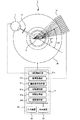
図1は、本発明の一実施形態であるX線回折装置の概略構成図である。
X線回折装置1は、X線源11と、スリット12と、ラインセンサ(X線検出器アレイ)13と、ゴニオメータ30と、X線回折装置1全体の制御を行う制御部(コンピュータ)20とを備える。
FIG. 1 is a schematic configuration diagram of an X-ray diffraction apparatus according to an embodiment of the present invention.
The X-ray diffraction apparatus 1 includes an X-ray source 11, a
ラインセンサ13は、N個(例えば1280個)の検出素子(半導体素子)が一次元に配列されている。そして、各検出素子が所定の積算時間をかけて検出されたX線強度In(検出素子番号n=1、2、・・・、N)が、制御部20にそれぞれ出力されるようになっている。積算時間は試料に応じて十分な強度のピーク信号が得られる程度に設定すればよく、例えば10〜30秒程度の積算時間が設定される。
また、ラインセンサ13は、ゴニオメータ30の2θ軸に搭載されるとともに、測定試料Sは、ゴニオメータ30のθ軸に搭載されるようになっており、θ−2θ連動の駆動方法で、ゴニオメータ30の中心軸を中心として付設の回転駆動機構(図示略)によりそれぞれ回転されるようになっている。そして本実施形態では当該回転駆動機構を用いてラインセンサ13が検出位置で搖動運動できるようにしてある。
In the
The
制御部20を構成するコンピュータは、CPU21と入力装置22と表示装置23とを備え、X線回折装置1全体の制御を行う。CPU21により行われる制御のうち、本発明に関係する機能をブロック化して説明すると、X線源制御部21aと、信号取得部21bと、画像表示制御部21c、回転制御部21d、補間処理部21e、搖動制御部21fとを有している。
A computer constituting the
X線源制御部21aは、X線源11から特性X線を出射させる制御を行う。
信号取得部21bは、入力装置22で設定した積算時間(例えば10秒)の間に、ラインセンサ13のN個の各検出素子が検出するX線強度信号Inをそれぞれ積算して取得する制御を行う。
画像表示制御部21cは、各検出素子により積算時間をかけて取得したX線強度信号Inを強度分布として画像表示する制御を行う。
回転制御部21dは、回折測定の際に試料Sとラインセンサ13とがθ−2θ連動の関係を保ちながら測定できるようにゴニオメータ30を回転する制御を行う。
補間処理部21eは、不良素子の存在による検出信号の欠落部分があるときに、その欠落部分を挟んだ両側の検出信号データに基づいて補間処理の演算を行う。
The X-ray source control unit 21 a performs control to emit characteristic X-rays from the X-ray source 11.
Image
The
When there is a missing portion of the detection signal due to the presence of a defective element, the
搖動制御部21fは、本発明による新たな機能を実現するために必要な制御を行う構成部分であり、積算時間中にゴニオメータ30の回転駆動機構を駆動してラインセンサ13を揺動させる制御を行う。この揺動は、積算時間中にラインセンサ13が整数回揺動するように制御される。例えば積算時間10秒間に整数回である1回、2回の揺動、あるいは5回以上の多数回の搖動(往復動)が行われるように制御される。なお、揺動回数が5回以上、好ましくは10回以上であれば、1回以下の揺動による信号全体への影響は十分小さいので、整数回の揺動となるよう正確に制御する必要はなくなる。本実施例では10秒間の積算時間で10回程度の揺動を行うようにしている。
The
次に測定動作について説明する。一般にX線回折装置1では測定内容に応じて、いくつかの測定モードが用意されている。具体的には、広い角度範囲で回折測定するためにラインセンサ13を連続的に回転走査し、あるいは、ラインセンサ13で測定可能な角度範囲幅ごとに間欠的に走査して測定する測定する「走査モード」が設けられている。
Next, the measurement operation will be described. In general, the X-ray diffractometer 1 is provided with several measurement modes depending on the measurement contents. Specifically, the
また、ピーク信号を検出する角度範囲が判明している試料等の測定であって、検出する角度範囲が狭くてよい場合には、ラインセンサ13を動かさずに回折測定を行うことができるため、ラインセンサ13を所望の角度範囲の検出位置にセットし、積算時間中はその検出位置で固定して測定する「固定測定モード」(ワンショットモード)も設けられている。なお、測定モードの選択は、入力装置22からの入力操作によって選択できるようにしてある。
Further, when measuring a sample or the like whose angle range for detecting the peak signal is known and the angle range to be detected may be narrow, diffraction measurement can be performed without moving the
そして本発明は、この「固定測定モード」を用いて不良素子の存在による悪影響を排除することが目的の一つであるため、以下は「固定測定モード」について説明するとともに、本発明を実行する際の「揺動測定モード」と対比しながら説明する。 Since the present invention has one object of eliminating the adverse effects due to the presence of defective elements using this “fixed measurement mode”, the following will explain the “fixed measurement mode” and execute the present invention. This will be described in comparison with the “oscillation measurement mode”.
「固定測定モード」により、積算時間中にラインセンサ13を検出位置に固定して測定すると、(後述する「揺動測定モード」よりも)高分解能でのX線信号の強度分布を得ることができる。しかしながらラインセンサ13のX線検出素子の一部に不良素子が含まれていると、その不良素子の位置に対応する信号が欠落することになり、その場合には補間処理部20eによって補間処理が行われることになる。
In the “fixed measurement mode”, when the
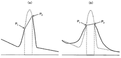
図2は、定性分析でピークトップ位置を求める場合のピーク付近の信号を示す図であり、図2(a)は「固定測定モード」測定時のX線信号において、不良素子存在時に検出される欠落信号プロファイル(太い実線部分)と、補間処理で求めた補間プロファイル(細い実線部分)とを示した信号波形の模式図である。なお、本来のピークプロファイル(点線部分)、すなわち、不良素子が存在しないときのピークプロファイルについても併せて示してある。図2では、不良素子の位置近傍に、たまたまピーク位置が存在した状態を示している。 FIG. 2 is a diagram showing a signal in the vicinity of the peak when the peak top position is obtained by qualitative analysis. FIG. 2A is an X-ray signal in the “fixed measurement mode” measurement, which is detected when a defective element is present. It is a schematic diagram of a signal waveform showing a missing signal profile (thick solid line portion) and an interpolation profile (thin solid line portion) obtained by interpolation processing. The original peak profile (dotted line portion), that is, the peak profile when there is no defective element is also shown. FIG. 2 shows a state in which a peak position happens to be near the position of the defective element.
この場合、「固定測定モード」では、高い分解能のピークが得られる結果、ピーク付近の信号高さは十分に高く、急峻な変化になっている。したがって不良素子が存在するときの補間プロファイルは、急峻に変化する位置で補間が行われることになり、ピークの幅方向のわずかな位置ずれがあると、(不良素子に隣接する)正常素子位置P1、P2の信号高さの変動は大きくなる。よって変動が大きい信号を用いて求めた補間プロファイルを利用して、ガウスフィッティング等でピークトップ位置を算出したとしても、ピークトップの位置は本来の位置から変動しやすく再現性も小さい。したがって、求めたピーク位置の信頼性は低く、ピーク位置を検知して定性分析を行う場合に、定性分析の判定ミスが起こりやすい。 In this case, in the “fixed measurement mode”, a high-resolution peak is obtained, and as a result, the signal height near the peak is sufficiently high and changes sharply. Therefore, the interpolation profile in the presence of a defective element is to be interpolated at a sharply changing position. If there is a slight positional deviation in the peak width direction, the normal element position P (adjacent to the defective element) is detected. 1, the variation of the signal level of the P 2 increases. Therefore, even if the peak top position is calculated by Gaussian fitting or the like using an interpolation profile obtained using a signal with large fluctuations, the peak top position is likely to fluctuate from the original position and has low reproducibility. Therefore, the reliability of the obtained peak position is low, and when the peak position is detected and the qualitative analysis is performed, a determination error in the qualitative analysis is likely to occur.
これに対し、X線回折装置1では、この「固定測定モード」に加えて、搖動制御部21fによりラインセンサ13を検出位置で揺動させながら同様の測定を行う「揺動測定モード」が追加されている。すなわち、入力装置22で「揺動測定モード」を選択することにより、積算時間中にラインセンサ13を検出位置で揺動させながらX線信号を取得する制御が行われる。
In contrast, in the X-ray diffraction apparatus 1, in addition to the “fixed measurement mode”, a “swing measurement mode” for performing the same measurement while swinging the
図2(b)は「揺動測定モード」測定時のX線ピーク信号において、不良素子存在時に検出される欠落信号プロファイル(太い実線部分)と、補間処理で求めた補間プロファイル(細い実線部分)とを示した信号波形の模式図である。なお、図2(a)と同様に本来のピークプロファイル(点線部分)も併せて示してある。
揺動が行われることによってX線信号が均される結果、欠落信号プロファイルは、ピーク中心付近の高さが本来のピーク高さよりも低くなり、ピークの裾野部分が本来のピーク高さよりも高くなり、全体的にブロードなピーク信号波形になる。したがって「固定測定モード」に比べて分解能が悪化している。
FIG. 2B shows a missing signal profile (thick solid line portion) detected when a defective element is present in the X-ray peak signal during the “oscillation measurement mode” measurement, and an interpolation profile (thin solid line portion) obtained by interpolation processing. It is the schematic diagram of the signal waveform which showed. The original peak profile (dotted line portion) is also shown in the same manner as in FIG.
As a result of the X-ray signal being leveled by swinging, the missing signal profile has a height near the peak center that is lower than the original peak height, and the base of the peak is higher than the original peak height. The peak signal waveform is broad as a whole. Therefore, the resolution is deteriorated compared to the “fixed measurement mode”.
しかし「揺動測定モード」では、不良素子が存在するときの補間プロファイルは、均されたピーク波形上での補間が行われることになり、ピークの幅方向の位置ずれがあっても(不良素子に隣接する)正常素子位置P1、P2の信号高さの変動は小さくなっている。よって補間プロファイルがあまり大きく変動しないので、ガウスフィッティング等でピークトップ位置を算出すると、このピークトップ位置は本来の位置からの変動値が小さくなり、再現性も大きい。したがって、求めたピーク位置の信頼性は高く、ピーク位置を検知して定性分析を行う場合に、定性分析の判定ミスが起こり難い。 However, in the “oscillation measurement mode”, the interpolation profile when there is a defective element is interpolated on the averaged peak waveform, and even if there is a positional deviation in the width direction of the peak (defective element) The fluctuations in the signal height of the normal element positions P 1 and P 2 (adjacent to) are small. Therefore, since the interpolation profile does not fluctuate so much, when the peak top position is calculated by Gaussian fitting or the like, the fluctuation value from the original position becomes small and the reproducibility is large. Therefore, the reliability of the obtained peak position is high, and when the peak position is detected and the qualitative analysis is performed, a determination error in the qualitative analysis hardly occurs.
また、図3は、定量分析でピーク面積比を求める場合のピーク付近の信号を示す図である。図3(a)は「固定測定モード」測定時の標準試料Sおよび未知試料UのX線ピーク信号において、不良素子存在時に検出される欠落信号プロファイル(太い実線部分)と、補間処理で求めた補間プロファイル(細い実線部分)とを示した信号波形の模式図であって、上側は標準試料Sの測定結果、下側は試料交換後の未知試料Uの測定結果を示している。なお、本来のピークプロファイル(点線部分)も併せて示してある。
定量測定では、試料交換による光路変化によって、ピーク位置が少しずれることがある。ピーク位置がずれることにより、急峻なピーク形状が得られている「固定測定モード」では、同一含有量の測定した場合でも、補間処理で求めたピーク面積が大きく異なりやすい。
これに対し、図3(b)は「揺動測定モード」測定時のX線ピーク信号において、不良素子存在時に検出される欠落信号プロファイル(太い実線部分)と、補間処理で求めた補間プロファイル(細い実線部分)とを示した信号波形の模式図である。なお、図3(a)と同様に本来のピークプロファイル(点線部分)も併せて示してある。
揺動が行われることによってX線信号が均される結果、全体的にブロードなピーク信号波形になる。定量測定でのピーク面積比においても「固定測定モード」に比べて変動が小さくなっており、定量値の誤差を小さく抑えることができる。
FIG. 3 is a diagram showing a signal in the vicinity of a peak when a peak area ratio is obtained by quantitative analysis. FIG. 3A shows the missing signal profile (thick solid line portion) detected when a defective element is present in the X-ray peak signals of the standard sample S and the unknown sample U in the “fixed measurement mode” measurement, and is obtained by interpolation processing. It is a schematic diagram of a signal waveform showing an interpolation profile (thin solid line part), the upper side shows the measurement result of the standard sample S, and the lower side shows the measurement result of the unknown sample U after the sample replacement. The original peak profile (dotted line portion) is also shown.
In quantitative measurement, the peak position may be slightly shifted due to a change in the optical path caused by sample exchange. In the “fixed measurement mode” in which a steep peak shape is obtained by shifting the peak position, even when the same content is measured, the peak areas obtained by the interpolation process are likely to vary greatly.
On the other hand, FIG. 3B shows a missing signal profile (thick solid line portion) detected when a defective element is present in the X-ray peak signal in the “swing measurement mode” measurement, and an interpolation profile obtained by interpolation processing ( It is a schematic diagram of a signal waveform showing a thin solid line portion). The original peak profile (dotted line portion) is also shown in the same manner as in FIG.
As a result of the swinging, the X-ray signal is leveled, resulting in an overall broad peak signal waveform. Also in the peak area ratio in the quantitative measurement, the fluctuation is smaller than that in the “fixed measurement mode”, and the error of the quantitative value can be suppressed small.
以上はX線回折装置1に本発明を実施した場合について説明したが、その他のX線測定装置にも本発明を適用することができる。
例えば、図4は本発明の他の一実施形態である蛍光X線分析装置2を示す概略構成図である。蛍光X線分析装置2は、試料Sに向けてX線を照射するX線源41と、試料Sから発生した蛍光X線を通過させるスリット42と、スリット42を介して入射する蛍光X線を分光する分光結晶43と、多数の検出素子が一次元に配列され、分光結晶により波長ごとに分散された蛍光X線を波長ごとに検出するラインセンサ44(X線検出器アレイ)とを備えている。
そしてこの蛍光X線分析装置2では、ラインセンサ44を検出素子の配列方向に搖動させる搖動機構45が新たに設けられている。
Although the case where the present invention is implemented in the X-ray diffraction apparatus 1 has been described above, the present invention can be applied to other X-ray measurement apparatuses.
For example, FIG. 4 is a schematic configuration diagram showing a
In this fluorescent
蛍光X線分析装置2の装置全体を制御する制御部(コンピュータ)50は、CPU51、入力装置52、表示装置53を有している。また、CPU51により行われる制御のうち、本発明に関係する機能をブロック化して説明すると、X線源制御部51aと、信号取得部51bと、画像表示制御部51cと、補間処理部51eと、搖動制御部51fとを有している。
これらは図1で説明したX線回折装置1におけるX線源制御部21a、信号取得部21b、画像表示制御部21c、補間処理部21e、搖動制御部21fと同様の制御を行うので説明を省略する。
A control unit (computer) 50 that controls the entire apparatus of the
Since these perform the same control as the X-ray source control unit 21a, the
そして蛍光X線分析装置2でも搖動機構45と搖動制御部51fとにより、X線回折装置1と同様の「搖動測定モード」での測定が行われる。よってラインセンサ44の一部に不良素子が存在するときには、「固定測定モード」に比べて誤差の小さい補間処理が可能になる。
In the
上述した実施例では、N個の検出素子が一次元に配列されたラインセンサを用いたが、(N×M)個の検出素子が二次元に配列されたX線検出器アレイを用いて二次元に搖動させるようにしてもよい。 In the above-described embodiment, a line sensor in which N detection elements are arranged one-dimensionally is used. However, an X-ray detector array in which (N × M) detection elements are arranged two-dimensionally is used. You may make it move to a dimension.
本発明は、X線回折装置や蛍光X線分析装置やX線測定装置等に利用することができる。 The present invention can be used for an X-ray diffraction apparatus, a fluorescent X-ray analysis apparatus, an X-ray measurement apparatus, and the like.
1 X線回折装置
2 蛍光X線分析装置
11、41 X線源
13、44 ラインセンサ(X線検出器アレイ)
20、50 制御部
30 ゴニオメータ(揺動機構)
21f、51f 搖動制御部
1
20, 50
21f, 51f Peristaltic control unit
Claims (4)
前記X線検出素子に欠落部分があるときに、前記欠落部分を挟んだ両側の検出信号データに基づいて補間処理を行う補間処理部と、
前記検出位置において前記X線検出素子の配列方向に沿って前記X線検出器アレイを前記欠落部分の幅を超える揺動幅で揺動する揺動機構と、
前記積算時間中に前記揺動機構を揺動させる揺動制御部とを備えたことを特徴とするX線測定装置。 An X-ray detector array in which X-ray detection elements are arranged one-dimensionally or two-dimensionally is arranged at a detection position for detecting an X-ray signal from a measurement target, and the X-ray signal is taken over a predetermined integration time. An X-ray measuring apparatus that integrates at a detection position and detects an X-ray signal integrated by each X-ray detection element during the integration time as an intensity distribution signal,
When there is a missing part in the X-ray detection element, an interpolation processing unit that performs an interpolation process based on detection signal data on both sides sandwiching the missing part;
A swinging mechanism that swings the X-ray detector array with a swinging width that exceeds the width of the missing portion along the arrangement direction of the X-ray detection elements at the detection position;
An X-ray measurement apparatus comprising: a swing control unit that swings the swing mechanism during the integration time.
前記揺動機構は前記回転駆動機構が兼用される請求項1又は請求項2に記載のX線測定装置。 The X-ray measuring device is an X-ray diffractometer provided with a goniometer, and the X-ray detector array is provided with a rotation drive mechanism for rotating around the rotation center of the goniometer,
The X-ray measurement apparatus according to claim 1, wherein the swing mechanism is also used as the rotation drive mechanism.
Priority Applications (1)
| Application Number | Priority Date | Filing Date | Title |
|---|---|---|---|
| JP2014068561A JP6256152B2 (en) | 2014-03-28 | 2014-03-28 | X-ray measuring device |
Applications Claiming Priority (1)
| Application Number | Priority Date | Filing Date | Title |
|---|---|---|---|
| JP2014068561A JP6256152B2 (en) | 2014-03-28 | 2014-03-28 | X-ray measuring device |
Publications (3)
| Publication Number | Publication Date |
|---|---|
| JP2015190868A JP2015190868A (en) | 2015-11-02 |
| JP2015190868A5 JP2015190868A5 (en) | 2016-08-25 |
| JP6256152B2 true JP6256152B2 (en) | 2018-01-10 |
Family
ID=54425464
Family Applications (1)
| Application Number | Title | Priority Date | Filing Date |
|---|---|---|---|
| JP2014068561A Active JP6256152B2 (en) | 2014-03-28 | 2014-03-28 | X-ray measuring device |
Country Status (1)
| Country | Link |
|---|---|
| JP (1) | JP6256152B2 (en) |
Families Citing this family (3)
| Publication number | Priority date | Publication date | Assignee | Title |
|---|---|---|---|---|
| JP2017067516A (en) | 2015-09-29 | 2017-04-06 | 株式会社ミツトヨ | Signal processing device for measurement apparatus |
| DE102016014213A1 (en) * | 2015-12-08 | 2017-07-06 | Shimadzu Corporation | X-RAY SPECTROSCOPIC ANALYSIS DEVICE AND ELEMENTARY ANALYSIS METHOD |
| JP2019211209A (en) * | 2018-05-31 | 2019-12-12 | 国立研究開発法人物質・材料研究機構 | Measurement method of diffracted x-ray intensity by one-dimensional or two-dimensional detector |
Family Cites Families (7)
| Publication number | Priority date | Publication date | Assignee | Title |
|---|---|---|---|---|
| JPS5698641A (en) * | 1980-01-09 | 1981-08-08 | Rigaku Denki Kk | X-ray diffraction device |
| JPS59186481A (en) * | 1983-04-08 | 1984-10-23 | Citizen Watch Co Ltd | Image pickup device |
| JPH0678913A (en) * | 1992-09-03 | 1994-03-22 | Toshiba Corp | Ct scanner |
| JP2003156565A (en) * | 2001-11-20 | 2003-05-30 | Canon Inc | Imaging device using photoelectric converter |
| GB2496484B (en) * | 2011-11-11 | 2016-04-06 | Rigaku Denki Co Ltd | X-Ray intensity correction method and x-ray diffractometer |
| JP5492173B2 (en) * | 2011-11-11 | 2014-05-14 | 株式会社リガク | Diffraction X-ray detection method and X-ray diffraction apparatus |
| JP5695589B2 (en) * | 2012-03-02 | 2015-04-08 | 株式会社リガク | X-ray intensity correction method and X-ray diffraction apparatus |
-
2014
- 2014-03-28 JP JP2014068561A patent/JP6256152B2/en active Active
Also Published As
| Publication number | Publication date |
|---|---|
| JP2015190868A (en) | 2015-11-02 |
Similar Documents
| Publication | Publication Date | Title |
|---|---|---|
| TWI392866B (en) | Appratus and method for inspection of a sample | |
| CN110726742B (en) | X-ray analysis device and optical axis adjustment method thereof | |
| TWI388821B (en) | X-ray fluorescence spectrometer and x-ray fluorescence analyzing method | |
| US10410825B2 (en) | Electron probe microanalyzer and storage medium | |
| US10712294B2 (en) | X-ray diffraction analysis method and X-ray diffraction analysis apparatus | |
| US9869632B2 (en) | Absorption spectrometer and method for measuring the concentration of a gaseous component of interest in a measurement gas | |
| CN109196340B (en) | Wavelength dispersive fluorescent X-ray analysis device and fluorescent X-ray analysis method using the same | |
| JP6340604B2 (en) | X-ray fluorescence analyzer | |
| JP6256152B2 (en) | X-ray measuring device | |
| JP6503145B2 (en) | Replacement site measuring device and replacement site measuring method | |
| CN109791116B (en) | Wavelength dispersion type fluorescent X-ray analyzer | |
| Tantau et al. | High accuracy energy determination and calibration of synchrotron radiation by powder diffraction | |
| JP5671059B2 (en) | Data set calibration | |
| JP3968350B2 (en) | X-ray diffraction apparatus and method | |
| JP2010025692A (en) | Device and method for detecting antigen concentration | |
| JP2020197410A (en) | X-ray analyzer | |
| WO2017169247A1 (en) | X-ray fluorescence analyzer and x-ray fluorescence analysis method | |
| JP2006145305A (en) | Surface testing device | |
| JP7367605B2 (en) | X-ray analyzer and peak search method | |
| JP6467684B2 (en) | X-ray fluorescence analyzer | |
| JP6653814B2 (en) | Sample recovery apparatus, sample recovery method, and X-ray fluorescence analyzer using the same | |
| JP4662370B2 (en) | Angle correction method and X-ray diffraction apparatus in X-ray diffraction measurement | |
| JP2010286288A (en) | Control method for x-ray spectrometer, and x-ray spectrometer using the same | |
| CN112051289A (en) | X-ray analyzer and peak search method | |
| JPH09304309A (en) | Method and device for analyzing substrate surface |
Legal Events
| Date | Code | Title | Description |
|---|---|---|---|
| A521 | Written amendment |
Free format text: JAPANESE INTERMEDIATE CODE: A523 Effective date: 20160706 |
|
| A621 | Written request for application examination |
Free format text: JAPANESE INTERMEDIATE CODE: A621 Effective date: 20160706 |
|
| A977 | Report on retrieval |
Free format text: JAPANESE INTERMEDIATE CODE: A971007 Effective date: 20170322 |
|
| A131 | Notification of reasons for refusal |
Free format text: JAPANESE INTERMEDIATE CODE: A131 Effective date: 20170404 |
|
| A521 | Written amendment |
Free format text: JAPANESE INTERMEDIATE CODE: A523 Effective date: 20170602 |
|
| TRDD | Decision of grant or rejection written | ||
| A01 | Written decision to grant a patent or to grant a registration (utility model) |
Free format text: JAPANESE INTERMEDIATE CODE: A01 Effective date: 20171107 |
|
| A61 | First payment of annual fees (during grant procedure) |
Free format text: JAPANESE INTERMEDIATE CODE: A61 Effective date: 20171120 |
|
| R151 | Written notification of patent or utility model registration |
Ref document number: 6256152 Country of ref document: JP Free format text: JAPANESE INTERMEDIATE CODE: R151 |