JP6244300B2 - Tissue ligation device and tension device therefor - Google Patents
Tissue ligation device and tension device therefor Download PDFInfo
- Publication number
- JP6244300B2 JP6244300B2 JP2014514623A JP2014514623A JP6244300B2 JP 6244300 B2 JP6244300 B2 JP 6244300B2 JP 2014514623 A JP2014514623 A JP 2014514623A JP 2014514623 A JP2014514623 A JP 2014514623A JP 6244300 B2 JP6244300 B2 JP 6244300B2
- Authority
- JP
- Japan
- Prior art keywords
- suture
- loop
- snare
- tension
- suture loop
- Prior art date
- Legal status (The legal status is an assumption and is not a legal conclusion. Google has not performed a legal analysis and makes no representation as to the accuracy of the status listed.)
- Active
Links
- 210000005248 left atrial appendage Anatomy 0.000 claims description 82
- 230000007246 mechanism Effects 0.000 claims description 81
- 239000003550 marker Substances 0.000 claims description 11
- 230000008878 coupling Effects 0.000 claims description 4
- 238000010168 coupling process Methods 0.000 claims description 4
- 238000005859 coupling reaction Methods 0.000 claims description 4
- 230000008520 organization Effects 0.000 claims description 2
- 210000001519 tissue Anatomy 0.000 description 84
- 238000000926 separation method Methods 0.000 description 80
- 238000000034 method Methods 0.000 description 65
- 241000226585 Antennaria plantaginifolia Species 0.000 description 18
- 239000000463 material Substances 0.000 description 18
- 230000002829 reductive effect Effects 0.000 description 14
- 230000000717 retained effect Effects 0.000 description 11
- 230000008859 change Effects 0.000 description 9
- 230000006870 function Effects 0.000 description 9
- 230000014759 maintenance of location Effects 0.000 description 9
- 210000002216 heart Anatomy 0.000 description 8
- 210000001008 atrial appendage Anatomy 0.000 description 7
- 208000007536 Thrombosis Diseases 0.000 description 6
- 210000005246 left atrium Anatomy 0.000 description 6
- 238000007726 management method Methods 0.000 description 6
- 230000009467 reduction Effects 0.000 description 6
- 239000008280 blood Substances 0.000 description 5
- 210000004369 blood Anatomy 0.000 description 5
- 230000036961 partial effect Effects 0.000 description 5
- 230000003014 reinforcing effect Effects 0.000 description 5
- 239000010935 stainless steel Substances 0.000 description 5
- 229910001220 stainless steel Inorganic materials 0.000 description 5
- 239000000126 substance Substances 0.000 description 5
- 238000012800 visualization Methods 0.000 description 5
- 230000015572 biosynthetic process Effects 0.000 description 4
- 230000006835 compression Effects 0.000 description 4
- 238000007906 compression Methods 0.000 description 4
- 230000008602 contraction Effects 0.000 description 4
- 230000006378 damage Effects 0.000 description 4
- 230000037361 pathway Effects 0.000 description 4
- BASFCYQUMIYNBI-UHFFFAOYSA-N platinum Chemical compound [Pt] BASFCYQUMIYNBI-UHFFFAOYSA-N 0.000 description 4
- -1 polyethylene Polymers 0.000 description 4
- 230000002028 premature Effects 0.000 description 4
- 230000002787 reinforcement Effects 0.000 description 4
- 206010003658 Atrial Fibrillation Diseases 0.000 description 3
- 102000008186 Collagen Human genes 0.000 description 3
- 108010035532 Collagen Proteins 0.000 description 3
- 229920004934 Dacron® Polymers 0.000 description 3
- 239000004677 Nylon Substances 0.000 description 3
- 239000011324 bead Substances 0.000 description 3
- 229920001436 collagen Polymers 0.000 description 3
- 210000003191 femoral vein Anatomy 0.000 description 3
- 238000002594 fluoroscopy Methods 0.000 description 3
- 238000005259 measurement Methods 0.000 description 3
- 229910001000 nickel titanium Inorganic materials 0.000 description 3
- 229920001778 nylon Polymers 0.000 description 3
- 210000003516 pericardium Anatomy 0.000 description 3
- 239000005020 polyethylene terephthalate Substances 0.000 description 3
- 238000003825 pressing Methods 0.000 description 3
- 238000007665 sagging Methods 0.000 description 3
- 210000005166 vasculature Anatomy 0.000 description 3
- 210000002417 xiphoid bone Anatomy 0.000 description 3
- 108010010803 Gelatin Proteins 0.000 description 2
- 229910000831 Steel Inorganic materials 0.000 description 2
- 230000002411 adverse Effects 0.000 description 2
- 210000003484 anatomy Anatomy 0.000 description 2
- 239000003146 anticoagulant agent Substances 0.000 description 2
- 229940127219 anticoagulant drug Drugs 0.000 description 2
- 238000013459 approach Methods 0.000 description 2
- 238000005452 bending Methods 0.000 description 2
- 230000017531 blood circulation Effects 0.000 description 2
- 210000000845 cartilage Anatomy 0.000 description 2
- 210000000038 chest Anatomy 0.000 description 2
- 210000000078 claw Anatomy 0.000 description 2
- 238000005520 cutting process Methods 0.000 description 2
- 230000007423 decrease Effects 0.000 description 2
- 238000002592 echocardiography Methods 0.000 description 2
- 239000008273 gelatin Substances 0.000 description 2
- 229920000159 gelatin Polymers 0.000 description 2
- 235000019322 gelatine Nutrition 0.000 description 2
- 235000011852 gelatine desserts Nutrition 0.000 description 2
- 239000004005 microsphere Substances 0.000 description 2
- 230000004048 modification Effects 0.000 description 2
- 238000012986 modification Methods 0.000 description 2
- 229910052697 platinum Inorganic materials 0.000 description 2
- 229920000728 polyester Polymers 0.000 description 2
- 239000012781 shape memory material Substances 0.000 description 2
- 230000000087 stabilizing effect Effects 0.000 description 2
- 239000010959 steel Substances 0.000 description 2
- 238000001356 surgical procedure Methods 0.000 description 2
- 210000002268 wool Anatomy 0.000 description 2
- 229920002818 (Hydroxyethyl)methacrylate Polymers 0.000 description 1
- 229920001651 Cyanoacrylate Polymers 0.000 description 1
- WOBHKFSMXKNTIM-UHFFFAOYSA-N Hydroxyethyl methacrylate Chemical compound CC(=C)C(=O)OCCO WOBHKFSMXKNTIM-UHFFFAOYSA-N 0.000 description 1
- MWCLLHOVUTZFKS-UHFFFAOYSA-N Methyl cyanoacrylate Chemical compound COC(=O)C(=C)C#N MWCLLHOVUTZFKS-UHFFFAOYSA-N 0.000 description 1
- 208000031481 Pathologic Constriction Diseases 0.000 description 1
- 229920002614 Polyether block amide Polymers 0.000 description 1
- 239000004698 Polyethylene Substances 0.000 description 1
- 229920000954 Polyglycolide Polymers 0.000 description 1
- 239000004743 Polypropylene Substances 0.000 description 1
- 229920005830 Polyurethane Foam Polymers 0.000 description 1
- 239000004372 Polyvinyl alcohol Substances 0.000 description 1
- FAPWRFPIFSIZLT-UHFFFAOYSA-M Sodium chloride Chemical compound [Na+].[Cl-] FAPWRFPIFSIZLT-UHFFFAOYSA-M 0.000 description 1
- 239000004809 Teflon Substances 0.000 description 1
- 229920006362 Teflon® Polymers 0.000 description 1
- QJVKUMXDEUEQLH-UHFFFAOYSA-N [B].[Fe].[Nd] Chemical compound [B].[Fe].[Nd] QJVKUMXDEUEQLH-UHFFFAOYSA-N 0.000 description 1
- 239000002253 acid Substances 0.000 description 1
- NIXOWILDQLNWCW-UHFFFAOYSA-N acrylic acid group Chemical group C(C=C)(=O)O NIXOWILDQLNWCW-UHFFFAOYSA-N 0.000 description 1
- 239000000853 adhesive Substances 0.000 description 1
- 238000004026 adhesive bonding Methods 0.000 description 1
- 230000001070 adhesive effect Effects 0.000 description 1
- 238000002583 angiography Methods 0.000 description 1
- 210000001367 artery Anatomy 0.000 description 1
- 230000008901 benefit Effects 0.000 description 1
- 229920002988 biodegradable polymer Polymers 0.000 description 1
- 239000004621 biodegradable polymer Substances 0.000 description 1
- 230000005540 biological transmission Effects 0.000 description 1
- 230000000740 bleeding effect Effects 0.000 description 1
- 210000001715 carotid artery Anatomy 0.000 description 1
- 239000003795 chemical substances by application Substances 0.000 description 1
- KPLQYGBQNPPQGA-UHFFFAOYSA-N cobalt samarium Chemical compound [Co].[Sm] KPLQYGBQNPPQGA-UHFFFAOYSA-N 0.000 description 1
- 238000009500 colour coating Methods 0.000 description 1
- QTCANKDTWWSCMR-UHFFFAOYSA-N costic aldehyde Natural products C1CCC(=C)C2CC(C(=C)C=O)CCC21C QTCANKDTWWSCMR-UHFFFAOYSA-N 0.000 description 1
- 229940072645 coumadin Drugs 0.000 description 1
- 239000013078 crystal Substances 0.000 description 1
- 230000003247 decreasing effect Effects 0.000 description 1
- 238000010586 diagram Methods 0.000 description 1
- 238000012377 drug delivery Methods 0.000 description 1
- 230000003073 embolic effect Effects 0.000 description 1
- JJJFUHOGVZWXNQ-UHFFFAOYSA-N enbucrilate Chemical compound CCCCOC(=O)C(=C)C#N JJJFUHOGVZWXNQ-UHFFFAOYSA-N 0.000 description 1
- 229950010048 enbucrilate Drugs 0.000 description 1
- 230000002169 extracardiac Effects 0.000 description 1
- 239000004744 fabric Substances 0.000 description 1
- 238000011049 filling Methods 0.000 description 1
- 239000012530 fluid Substances 0.000 description 1
- 238000011010 flushing procedure Methods 0.000 description 1
- 239000006260 foam Substances 0.000 description 1
- 239000000499 gel Substances 0.000 description 1
- 238000002695 general anesthesia Methods 0.000 description 1
- 230000036541 health Effects 0.000 description 1
- 210000002837 heart atrium Anatomy 0.000 description 1
- 229920001477 hydrophilic polymer Polymers 0.000 description 1
- 238000003384 imaging method Methods 0.000 description 1
- 230000003601 intercostal effect Effects 0.000 description 1
- 230000001788 irregular Effects 0.000 description 1
- ISTFUJWTQAMRGA-UHFFFAOYSA-N iso-beta-costal Natural products C1C(C(=C)C=O)CCC2(C)CCCC(C)=C21 ISTFUJWTQAMRGA-UHFFFAOYSA-N 0.000 description 1
- 238000002955 isolation Methods 0.000 description 1
- PMHURSZHKKJGBM-UHFFFAOYSA-N isoxaben Chemical compound O1N=C(C(C)(CC)CC)C=C1NC(=O)C1=C(OC)C=CC=C1OC PMHURSZHKKJGBM-UHFFFAOYSA-N 0.000 description 1
- 210000004731 jugular vein Anatomy 0.000 description 1
- 239000007788 liquid Substances 0.000 description 1
- 239000000696 magnetic material Substances 0.000 description 1
- 238000004519 manufacturing process Methods 0.000 description 1
- 229910052751 metal Inorganic materials 0.000 description 1
- 239000002184 metal Substances 0.000 description 1
- 229910001172 neodymium magnet Inorganic materials 0.000 description 1
- HLXZNVUGXRDIFK-UHFFFAOYSA-N nickel titanium Chemical compound [Ti].[Ti].[Ti].[Ti].[Ti].[Ti].[Ti].[Ti].[Ti].[Ti].[Ti].[Ni].[Ni].[Ni].[Ni].[Ni].[Ni].[Ni].[Ni].[Ni].[Ni].[Ni].[Ni].[Ni].[Ni] HLXZNVUGXRDIFK-UHFFFAOYSA-N 0.000 description 1
- 238000002355 open surgical procedure Methods 0.000 description 1
- 210000000056 organ Anatomy 0.000 description 1
- 239000004033 plastic Substances 0.000 description 1
- 229920003023 plastic Polymers 0.000 description 1
- 229920000747 poly(lactic acid) Polymers 0.000 description 1
- 229920000573 polyethylene Polymers 0.000 description 1
- 239000004633 polyglycolic acid Substances 0.000 description 1
- 239000004626 polylactic acid Substances 0.000 description 1
- 229920000642 polymer Polymers 0.000 description 1
- 229920001155 polypropylene Polymers 0.000 description 1
- 229920001343 polytetrafluoroethylene Polymers 0.000 description 1
- 239000004810 polytetrafluoroethylene Substances 0.000 description 1
- 239000011496 polyurethane foam Substances 0.000 description 1
- 229920002451 polyvinyl alcohol Polymers 0.000 description 1
- QQONPFPTGQHPMA-UHFFFAOYSA-N propylene Natural products CC=C QQONPFPTGQHPMA-UHFFFAOYSA-N 0.000 description 1
- 125000004805 propylene group Chemical group [H]C([H])([H])C([H])([*:1])C([H])([H])[*:2] 0.000 description 1
- 229910052761 rare earth metal Inorganic materials 0.000 description 1
- 150000002910 rare earth metals Chemical class 0.000 description 1
- 239000012858 resilient material Substances 0.000 description 1
- 230000004044 response Effects 0.000 description 1
- 230000002441 reversible effect Effects 0.000 description 1
- 229910001285 shape-memory alloy Inorganic materials 0.000 description 1
- 239000002356 single layer Substances 0.000 description 1
- 239000011780 sodium chloride Substances 0.000 description 1
- 230000006641 stabilisation Effects 0.000 description 1
- 238000011105 stabilization Methods 0.000 description 1
- 230000036262 stenosis Effects 0.000 description 1
- 208000037804 stenosis Diseases 0.000 description 1
- 230000001732 thrombotic effect Effects 0.000 description 1
- 230000000451 tissue damage Effects 0.000 description 1
- 231100000827 tissue damage Toxicity 0.000 description 1
- 238000013175 transesophageal echocardiography Methods 0.000 description 1
- 238000002604 ultrasonography Methods 0.000 description 1
- 210000003462 vein Anatomy 0.000 description 1
- 238000007794 visualization technique Methods 0.000 description 1
- PJVWKTKQMONHTI-UHFFFAOYSA-N warfarin Chemical compound OC=1C2=CC=CC=C2OC(=O)C=1C(CC(=O)C)C1=CC=CC=C1 PJVWKTKQMONHTI-UHFFFAOYSA-N 0.000 description 1
- 238000003466 welding Methods 0.000 description 1
- 238000004804 winding Methods 0.000 description 1
Images


Classifications
-
- A—HUMAN NECESSITIES
- A61—MEDICAL OR VETERINARY SCIENCE; HYGIENE
- A61B—DIAGNOSIS; SURGERY; IDENTIFICATION
- A61B17/00—Surgical instruments, devices or methods, e.g. tourniquets
- A61B17/12—Surgical instruments, devices or methods, e.g. tourniquets for ligaturing or otherwise compressing tubular parts of the body, e.g. blood vessels, umbilical cord
- A61B17/12009—Implements for ligaturing other than by clamps or clips, e.g. using a loop with a slip knot
- A61B17/12013—Implements for ligaturing other than by clamps or clips, e.g. using a loop with a slip knot for use in minimally invasive surgery, e.g. endoscopic surgery
-
- A—HUMAN NECESSITIES
- A61—MEDICAL OR VETERINARY SCIENCE; HYGIENE
- A61B—DIAGNOSIS; SURGERY; IDENTIFICATION
- A61B17/00—Surgical instruments, devices or methods, e.g. tourniquets
- A61B17/04—Surgical instruments, devices or methods, e.g. tourniquets for suturing wounds; Holders or packages for needles or suture materials
- A61B17/0469—Suturing instruments for use in minimally invasive surgery, e.g. endoscopic surgery
-
- A—HUMAN NECESSITIES
- A61—MEDICAL OR VETERINARY SCIENCE; HYGIENE
- A61B—DIAGNOSIS; SURGERY; IDENTIFICATION
- A61B17/00—Surgical instruments, devices or methods, e.g. tourniquets
- A61B2017/00017—Electrical control of surgical instruments
- A61B2017/00115—Electrical control of surgical instruments with audible or visual output
-
- A—HUMAN NECESSITIES
- A61—MEDICAL OR VETERINARY SCIENCE; HYGIENE
- A61B—DIAGNOSIS; SURGERY; IDENTIFICATION
- A61B17/00—Surgical instruments, devices or methods, e.g. tourniquets
- A61B17/00234—Surgical instruments, devices or methods, e.g. tourniquets for minimally invasive surgery
- A61B2017/00238—Type of minimally invasive operation
- A61B2017/00243—Type of minimally invasive operation cardiac
-
- A—HUMAN NECESSITIES
- A61—MEDICAL OR VETERINARY SCIENCE; HYGIENE
- A61B—DIAGNOSIS; SURGERY; IDENTIFICATION
- A61B17/00—Surgical instruments, devices or methods, e.g. tourniquets
- A61B2017/00477—Coupling
-
- A—HUMAN NECESSITIES
- A61—MEDICAL OR VETERINARY SCIENCE; HYGIENE
- A61B—DIAGNOSIS; SURGERY; IDENTIFICATION
- A61B17/00—Surgical instruments, devices or methods, e.g. tourniquets
- A61B2017/00831—Material properties
- A61B2017/00867—Material properties shape memory effect
-
- A—HUMAN NECESSITIES
- A61—MEDICAL OR VETERINARY SCIENCE; HYGIENE
- A61B—DIAGNOSIS; SURGERY; IDENTIFICATION
- A61B17/00—Surgical instruments, devices or methods, e.g. tourniquets
- A61B17/02—Surgical instruments, devices or methods, e.g. tourniquets for holding wounds open; Tractors
- A61B17/0218—Surgical instruments, devices or methods, e.g. tourniquets for holding wounds open; Tractors for minimally invasive surgery
- A61B2017/0225—Surgical instruments, devices or methods, e.g. tourniquets for holding wounds open; Tractors for minimally invasive surgery flexible, e.g. fabrics, meshes, or membranes
-
- A—HUMAN NECESSITIES
- A61—MEDICAL OR VETERINARY SCIENCE; HYGIENE
- A61B—DIAGNOSIS; SURGERY; IDENTIFICATION
- A61B90/00—Instruments, implements or accessories specially adapted for surgery or diagnosis and not covered by any of the groups A61B1/00 - A61B50/00, e.g. for luxation treatment or for protecting wound edges
- A61B90/03—Automatic limiting or abutting means, e.g. for safety
- A61B2090/037—Automatic limiting or abutting means, e.g. for safety with a frangible part, e.g. by reduced diameter
-
- A—HUMAN NECESSITIES
- A61—MEDICAL OR VETERINARY SCIENCE; HYGIENE
- A61B—DIAGNOSIS; SURGERY; IDENTIFICATION
- A61B90/00—Instruments, implements or accessories specially adapted for surgery or diagnosis and not covered by any of the groups A61B1/00 - A61B50/00, e.g. for luxation treatment or for protecting wound edges
- A61B90/06—Measuring instruments not otherwise provided for
- A61B2090/064—Measuring instruments not otherwise provided for for measuring force, pressure or mechanical tension
Landscapes
- Health & Medical Sciences (AREA)
- Surgery (AREA)
- Life Sciences & Earth Sciences (AREA)
- Heart & Thoracic Surgery (AREA)
- Nuclear Medicine, Radiotherapy & Molecular Imaging (AREA)
- Engineering & Computer Science (AREA)
- Biomedical Technology (AREA)
- Medical Informatics (AREA)
- Molecular Biology (AREA)
- Animal Behavior & Ethology (AREA)
- General Health & Medical Sciences (AREA)
- Public Health (AREA)
- Veterinary Medicine (AREA)
- Vascular Medicine (AREA)
- Reproductive Health (AREA)
- Surgical Instruments (AREA)
Description
(関連出願の引用)
本願は、米国仮出願第61/494,845号(2011年6月8日出願)を基礎とする優先権を主張する。該出願は、その全体が参照により本明細書に引用される。
(Citation of related application)
This application claims priority based on US Provisional Application No. 61 / 494,845 (filed Jun. 8, 2011). The application is hereby incorporated by reference in its entirety.
(分野)
本発明は、概して、外科的、低侵襲的、または血管内アプローチを使用して、左心耳等の組織を結紮するための装置および方法と、これらの装置を作動させるための引張装置とに関する。
(Field)
The present invention relates generally to devices and methods for ligating tissue, such as the left atrial appendage, using surgical, minimally invasive, or endovascular approaches, and tensioning devices for operating these devices.
心房細動は何百万もの患者を苦しめている一般的問題である。心房細動は、左心房の心耳において血栓や凝血塊の形成をしばしば招く。血栓が移動し遠隔臓器を閉塞すると、卒中等の有害事象が起こり得、問題となる。このために、心房細動を患う患者のほとんどは、血栓の形成を防ぐため1つ以上の抗凝血剤による治療を受けている。ただし抗凝血剤は、特に高齢者において健康上のリスクを投げかける。出血等のこれらのリスクのために、利用者にはライフスタイルの大幅な変化がしばしば要求される。 Atrial fibrillation is a common problem afflicting millions of patients. Atrial fibrillation often results in the formation of blood clots and clots in the left atrial appendage. If the thrombus moves and occludes a distant organ, adverse events such as stroke can occur and become a problem. For this reason, most patients with atrial fibrillation are treated with one or more anticoagulants to prevent thrombus formation. However, anticoagulants pose a health risk, especially in the elderly. Because of these risks such as bleeding, users are often required to make significant lifestyle changes.
左心耳における血栓形成の潜在的問題に対処するために、いくつかの方法が開発されてきた。一方法では、左心耳を、その基部すなわち、左心耳が心房とつながる入口狭窄部に沿って縫合する。こうすることで心耳内への血流は遮断され、心耳における血栓形成リスクはなくなる。通常これは心臓切開手術によって行われるが、特に高リスクの人や心臓切開手技を別途受けている人への適用は制限される。加えて、心臓切開手術には全身麻酔が必要となるほか周知のリスクが数多くあるために、あまり望ましくない。 Several methods have been developed to address the potential problem of thrombus formation in the left atrial appendage. In one method, the left atrial appendage is sutured along its base, ie the entrance stenosis where the left atrial appendage connects to the atrium. By doing so, blood flow into the atrial appendage is blocked, and the risk of thrombus formation in the atrial appendage is eliminated. This is usually done by open heart surgery, but its application is limited, especially for people at high risk and those who have undergone separate open heart procedures. In addition, open heart surgery is less desirable because it requires general anesthesia and has many known risks.
他の方法も、検討されてきた。これらの方法には、心耳の基部をステープルで留める方法や、空間を占拠または閉塞する部材で心耳を満たす方法がある。心耳は脆く破裂しやすいためステープリングは好ましくなく、閉塞装置は心耳内への全血流を効果的に防がない場合がある。 Other methods have been considered. These methods include a method of stapling the base of the atrial appendage and a method of filling the atrial appendage with a member that occupies or closes the space. The atrial appendage is brittle and easily ruptured, so stapling is not preferred and the occlusion device may not effectively prevent total blood flow into the atrial appendage.
したがって、左心耳や他の適切な組織を閉鎖するさらなる装置および方法が望まれる。特に、胸部を切開する必要を回避するためには、低侵襲技法、血管内技法、またはこれらの技法の組み合わせを使用し左心耳を閉鎖する装置および方法が望まれるであろう。当然ながら、切開外科手技用のさらなる装置も、特にこれが標準的な装置を凌ぐさらなる利点を提供するなら望ましい。 Accordingly, additional devices and methods for closing the left atrial appendage and other suitable tissues are desired. In particular, devices and methods for closing the left atrial appendage using minimally invasive techniques, intravascular techniques, or a combination of these techniques would be desirable to avoid the need to open the chest. Of course, additional devices for open surgical procedures are also desirable, especially if this provides additional advantages over standard devices.
本発明は、例えば、以下を提供する:
(項目1)
標的組織を閉鎖する方法であって、
閉鎖装置を身体内に導入することであって、前記閉鎖装置は、開放構成および閉鎖構成を有するスネアループアセンブリを備え、前記スネアループアセンブリは、前記スネアループアセンブリに解放可能に連結される縫合糸ループを備えている、ことと、
スネアループアセンブリを前進させ、前記標的組織を捕捉することと、
前記スネアループアセンブリを前記標的組織の周囲で閉鎖することと、
第1の所定の張力を前記縫合糸ループに与え、前記縫合糸ループを前記スネアループアセンブリから解放することと、
第2の所定の張力を前記縫合糸ループに与え、前記縫合糸ループを前記標的組織の周囲で締め付けることと
を含む、方法。
(項目2)
前記標的組織は、左心耳である、項目1に記載の方法。
(項目3)
前記縫合糸ループを前記スネアループアセンブリから解放後、前記スネアループアセンブリを前記開放構成に開放することをさらに含む、項目1に記載の方法。
(項目4)
前記第2の所定の張力を前記縫合糸ループに与えることに続いて、第1の時間後、前記縫合糸ループを再度締め付けることをさらに含む、項目1に記載の方法。
(項目5)
前記第1の時間は、少なくとも30秒である、項目4に記載の方法。
(項目6)
前記第1の時間は、少なくとも2分である、項目4に記載の方法。
(項目7)
前記縫合糸ループを再度締め付けることは、第3の所定の張力を前記縫合糸ループに与えることを含む、項目4に記載の方法。
(項目8)
前記縫合糸ループを再度締め付けることは、前記第2の所定の張力を前記縫合糸ループに与えることを含む、項目4に記載の方法。
(項目9)
前記第2の所定の張力は、前記第1の所定の張力より大きい、項目1に記載の方法。
(項目10)
前記第1の所定の張力は、前記第2の所定の張力より大きい、項目1に記載の方法。
(項目11)
前記第1の所定の張力は、少なくとも約6ポンド(約26.7ニュートン)である、項目1に記載の方法。
(項目12)
前記第2の所定の張力は、少なくとも約10ポンド(約44.5ニュートン)である、項目1に記載の方法。
(項目13)
前記第1の所定の張力を前記縫合糸ループに与えることは、第1の引張装置を使用して、前記第1の所定の張力を前記縫合糸ループに与えることを含む、項目1に記載の方法。
(項目14)
前記第2の所定の張力を前記縫合糸ループに与えることは、前記第1の引張装置を使用して、前記第2の所定の張力を前記縫合糸ループに与えることを含む、項目13に記載の方法。
(項目15)
前記第2の所定の張力を前記縫合糸ループに与えることは、第2の引張装置を使用して、前記第2の所定の張力を前記縫合糸ループに与えることを含む、項目13に記載の方法。
(項目16)
前記引張装置は、前記引張装置を前記縫合糸ループの一部に連結するための縫合糸取付機構、力ゲージ、および力インジケータを備えている、項目13に記載の方法。
(項目17)
前記引張装置は、回転ノブ、糸巻部材、第1のクラッチ、および第2のクラッチを備えている、項目13に記載の方法。
(項目18)
前記引張装置は、筐体と、第1の延長部材と、前記筐体および前記第1の延長部材に取り付けられた第1の一定力バネとを備えている、項目13に記載の方法。
(項目19)
組織を閉鎖するための装置であって、
スネアループアセンブリを備えている閉鎖装置であって、前記スネアループアセンブリは、前記スネアループアセンブリに解放可能に連結される縫合糸ループを有する、閉鎖装置と、
引張装置であって、前記引張装置は、前記引張装置を前記縫合糸ループの一部に連結するための縫合糸取付機構、力ゲージ、および力インジケータを備えている、引張装置と
を備えている、装置。
(項目20)
前記縫合糸ループの尾部は、縫合糸フォブに接続され、前記縫合糸取付機構は、前記縫合糸フォブを受け取り、保持するためのサイズおよび形状を有する開口を備えている、項目19に記載の装置。
(項目21)
前記力インジケータは、デジタルディスプレイを備えている、項目19に記載の装置。
(項目22)
組織を閉鎖するための装置であって、
スネアループアセンブリおよびハンドルを備えている閉鎖装置であって、前記スネアループアセンブリは、前記スネアループアセンブリに解放可能に連結される縫合糸ループを備えている、閉鎖装置と、
引張装置であって、基部、回転ノブ、糸巻部材、第1のクラッチ、および第2のクラッチを備えている、引張装置と
を備えている、装置。
(項目23)
前記引張装置の基部は、前記閉鎖装置のハンドルに取り付けられている、項目22に記載の装置。
(項目24)
前記回転ノブは、スイッチおよび係合ロッドを備え、前記スイッチは、前記係合ロッドが、前記第2のクラッチに対して回転し得る第1の位置と、前記係合ロッドが、第2のクラッチに係合し、前記第2のクラッチに回転可能に接続されている第2の位置との間で移動可能である、項目22に記載の装置。
(項目25)
前記縫合糸ループの一部は、前記糸巻部材に連結されている、項目22に記載の装置。
(項目26)
組織を閉鎖するためのシステムであって、
スネアループアセンブリを備えている閉鎖装置であって、前記スネアループアセンブリは、前記スネアループアセンブリに解放可能に連結される縫合糸ループを有する、閉鎖装置と、
引張装置であって、前記引張装置は、筐体と、筐体に対してスライド可能な第1の延長部材と、前記筐体および前記第1の延長部材に取り付けられた第1の一定力バネと、前記引張装置を前記縫合糸ループの一部に連結するための縫合糸取付機構とを備えている、引張装置と
を備えている、システム。
(項目27)
第2の延長部材および第2の一定力バネをさらに備え、前記第2の一定力バネは、前記筐体および前記第2の延長部材に取り付けられている、項目26に記載の装置。
(項目28)
前記第1の延長部材は、前記第2の延長部材に解放可能に連結可能である、項目27に記載の装置。
(項目29)
組織を閉鎖するための装置であって、
ハンドルと、スネアループアセンブリとを備えている閉鎖装置であって、前記スネアループアセンブリは、前記スネアループアセンブリに解放可能に連結される縫合糸ループを有する、閉鎖装置と、
引張機構であって、前記引張機構は、回転ノブと、インジケータ本体と、前記回転ノブと前記インジケータ本体とを回転可能に接続しているバネ部材とを備え、前記回転ノブの回転は、前記縫合糸ループを締め付け、前記インジケータ本体に対する前記回転ノブの回転は、前記縫合糸ループに与えられている力の量を示す、引張機構と
を備えている、装置。
(項目30)
心棒をさらに備え、前記インジケータ本体と前記心棒とは、固定して接続され、前記インジケータ本体および心棒は、前記ハンドルに回転可能に連結されている、項目29に記載の装置。
(項目31)
糸巻をさらに備え、前記心棒の回転は、前記糸巻を回転させる、項目30に記載の装置。
(項目32)
前記インジケータ本体は、少なくとも1つのマーキングを備え、前記回転ノブは、少なくとも1つのマーキングを備え、前記インジケータ本体の前記少なくとも1つのマーキングと前記回転ノブの前記少なくとも1つのマーキングとの間の相対的位置付けは、前記縫合糸ループに与えられている力の量を示す、項目29に記載の装置。
本明細書に説明されるのは、1つ以上の組織を閉鎖するための閉鎖装置と、これらの装置を制御するための機構である。概して、本明細書に説明される閉鎖装置は、スネアループアセンブリであって、スネアおよび縫合糸ループを備えている、スネアループアセンブリと、細長い本体と、ハンドル上に搭載され得る、スネアループアセンブリを制御するための機構とを備えている。いくつかの変形例では、スネアループアセンブリは、縫合糸ループおよびスネアを解放可能に連結し得る、保持部材を備え得る。他の変形例では、装置は、縫合糸ループがスネアループアセンブリから偶発的に係合解除しないように防止するのに役立つ1つ以上の減力縫合糸ロックを備えている。加えて、閉鎖装置は、縫合糸ループを引張または別様に締め付けるための1つ以上の引張装置を備え得る。
The present invention provides, for example:
(Item 1)
A method for closing a target tissue,
Introducing a closure device into a body, the closure device comprising a snare loop assembly having an open configuration and a closed configuration, wherein the snare loop assembly is releasably coupled to the snare loop assembly With a loop,
Advancing a snare loop assembly to capture the target tissue;
Closing the snare loop assembly around the target tissue;
Applying a first predetermined tension to the suture loop and releasing the suture loop from the snare loop assembly;
Applying a second predetermined tension to the suture loop and tightening the suture loop around the target tissue.
(Item 2)
The method of item 1, wherein the target tissue is the left atrial appendage.
(Item 3)
The method of claim 1, further comprising releasing the snare loop assembly to the open configuration after releasing the suture loop from the snare loop assembly.
(Item 4)
The method of claim 1, further comprising re-tightening the suture loop after a first time following applying the second predetermined tension to the suture loop.
(Item 5)
Item 5. The method of item 4, wherein the first time is at least 30 seconds.
(Item 6)
Item 5. The method of item 4, wherein the first time is at least 2 minutes.
(Item 7)
5. The method of item 4, wherein retightening the suture loop includes applying a third predetermined tension to the suture loop.
(Item 8)
5. The method of item 4, wherein retightening the suture loop includes applying the second predetermined tension to the suture loop.
(Item 9)
Item 2. The method of item 1, wherein the second predetermined tension is greater than the first predetermined tension.
(Item 10)
The method of item 1, wherein the first predetermined tension is greater than the second predetermined tension.
(Item 11)
The method of claim 1, wherein the first predetermined tension is at least about 6 pounds (about 26.7 Newtons) .
(Item 12)
The method of claim 1, wherein the second predetermined tension is at least about 10 pounds (about 44.5 Newtons) .
(Item 13)
2. The item of claim 1, wherein applying the first predetermined tension to the suture loop includes applying a first predetermined tension to the suture loop using a first tensioning device. Method.
(Item 14)
14. The item 13, wherein applying the second predetermined tension to the suture loop includes applying the second predetermined tension to the suture loop using the first tensioning device. the method of.
(Item 15)
14. The item of claim 13, wherein applying the second predetermined tension to the suture loop includes applying a second predetermined tension to the suture loop using a second tensioning device. Method.
(Item 16)
14. The method of item 13, wherein the tensioning device comprises a suture attachment mechanism, a force gauge, and a force indicator for connecting the tensioning device to a portion of the suture loop.
(Item 17)
14. A method according to item 13, wherein the tensioning device comprises a rotary knob, a pincushion member, a first clutch, and a second clutch.
(Item 18)
14. The method of item 13, wherein the tensioning device comprises a housing, a first extension member, and a first constant force spring attached to the housing and the first extension member.
(Item 19)
A device for closing tissue,
A closure device comprising a snare loop assembly, the snare loop assembly having a suture loop releasably coupled to the snare loop assembly;
A tensioning device, the tensioning device comprising a suture attachment mechanism, a force gauge, and a force indicator for coupling the tensioning device to a portion of the suture loop. ,apparatus.
(Item 20)
The apparatus of item 19, wherein the tail of the suture loop is connected to a suture fob and the suture attachment mechanism comprises an opening having a size and shape for receiving and holding the suture fob. .
(Item 21)
Item 20. The apparatus of item 19, wherein the force indicator comprises a digital display.
(Item 22)
A device for closing tissue,
A closure device comprising a snare loop assembly and a handle, the snare loop assembly comprising a suture loop releasably coupled to the snare loop assembly;
A tensioning device comprising a base, a rotary knob, a pincushion member, a first clutch, and a second clutch, and a tensioning device.
(Item 23)
Item 23. The device of item 22, wherein the base of the tensioning device is attached to the handle of the closure device.
(Item 24)
The rotation knob includes a switch and an engagement rod, and the switch includes a first position where the engagement rod can rotate with respect to the second clutch, and the engagement rod includes a second clutch. 23. The apparatus of item 22, wherein the apparatus is movable between a second position engaged with the second clutch and rotatably connected to the second clutch.
(Item 25)
24. The apparatus of item 22, wherein a portion of the suture loop is coupled to the spool member.
(Item 26)
A system for closing an organization,
A closure device comprising a snare loop assembly, the snare loop assembly having a suture loop releasably coupled to the snare loop assembly;
A tension device, wherein the tension device includes a housing, a first extension member slidable with respect to the housing, and a first constant force spring attached to the housing and the first extension member. And a tensioning device comprising a suture attachment mechanism for coupling the tensioning device to a portion of the suture loop.
(Item 27)
27. The apparatus of item 26, further comprising a second extension member and a second constant force spring, wherein the second constant force spring is attached to the housing and the second extension member.
(Item 28)
28. The apparatus of item 27, wherein the first extension member is releasably connectable to the second extension member.
(Item 29)
A device for closing tissue,
A closure device comprising a handle and a snare loop assembly, the snare loop assembly having a suture loop releasably coupled to the snare loop assembly;
The tension mechanism includes a rotation knob, an indicator body, and a spring member that rotatably connects the rotation knob and the indicator body, and the rotation of the rotation knob is performed by the suturing mechanism. A device comprising: a tensioning mechanism that tightens a thread loop and rotation of the rotary knob relative to the indicator body indicates an amount of force applied to the suture loop.
(Item 30)
30. The apparatus of item 29, further comprising a mandrel, wherein the indicator body and the mandrel are fixedly connected and the indicator body and mandrel are rotatably coupled to the handle.
(Item 31)
The apparatus of item 30, further comprising a spool, wherein rotation of the mandrel rotates the spool.
(Item 32)
The indicator body comprises at least one marking, the rotary knob comprises at least one marking, and the relative positioning between the at least one marking on the indicator body and the at least one marking on the rotary knob 30. The apparatus according to item 29, wherein indicates the amount of force applied to the suture loop.
Described herein are closure devices for closing one or more tissues and mechanisms for controlling these devices. In general, the closure devices described herein include a snare loop assembly comprising a snare loop assembly comprising a snare and a suture loop, an elongate body, and a snare loop assembly that can be mounted on a handle. And a mechanism for controlling. In some variations, the snare loop assembly may comprise a retaining member that may releasably couple the suture loop and snare. In other variations, the device includes one or more reducing suture locks that help prevent the suture loop from accidentally disengaging from the snare loop assembly. In addition, the closure device may comprise one or more tensioning devices for tensioning or otherwise tightening the suture loop.
いくつかの変形例では、引張装置は、力ゲージを備え得る。いくつかの変形例では、引張装置はさらに、ハンドル部分と、縫合糸取付機構と、力インジケータとを備え得る。縫合糸取付機構は、恒久的または可逆的に、縫合糸ループの一部(例えば、縫合糸の尾部)に連結可能な1つ以上の構造であり得る。いくつかの変形例では、縫合糸取付機構は、縫合糸ループの一部と係合する縫合糸フォブに取り付くように構成され得る。いくつかの変形例では、縫合糸取付機構は、引張装置によって縫合糸に与えられる張力が、力ゲージによって測定され得るように、力ゲージに取り付けられ得る。力インジケータを含む変形例では、力インジケータは、力ゲージによって測定される張力の指示を与え得る。いくつかの変形例では、力インジケータは、力ゲージによって測定された力を表示し得る、デジタルディスプレイを備え得る。他の変形例では、力インジケータは、力ゲージによって測定された張力が、1つ以上の所定の張力レベルに達すると、オン(または、オフ)になり得る、1つ以上の表示ランプを備え得る。他の変形例では、力インジケータは、力ゲージによって測定された張力の関数として、スケールに沿って移動し得る可動マーカを備え得る。いくつかの変形例では、スケールは、1つ以上の所定の張力値を表し得る1つ以上のマークを備え得る。 In some variations, the tensioning device may comprise a force gauge. In some variations, the tensioning device may further comprise a handle portion, a suture attachment mechanism, and a force indicator. The suture attachment mechanism can be one or more structures that can be permanently or reversibly coupled to a portion of the suture loop (eg, the tail of the suture). In some variations, the suture attachment mechanism may be configured to attach to a suture fob that engages a portion of the suture loop. In some variations, the suture attachment mechanism can be attached to the force gauge such that the tension applied to the suture by the tensioning device can be measured by the force gauge. In variations that include a force indicator, the force indicator may provide an indication of the tension measured by the force gauge. In some variations, the force indicator may comprise a digital display that may display the force measured by the force gauge. In other variations, the force indicator may comprise one or more indicator lamps that may be turned on (or off) when the tension measured by the force gauge reaches one or more predetermined tension levels. . In other variations, the force indicator may comprise a movable marker that may move along the scale as a function of the tension measured by the force gauge. In some variations, the scale may comprise one or more marks that may represent one or more predetermined tension values.
他の変形例では、引張装置は、1つ以上のクラッチを備え得る。いくつかの変形例では、引張装置は、基部、回転ノブ、糸巻部材、第1のクラッチ、および第2のクラッチを備え得る。いくつかの変形例では、引張部材の基部は、閉鎖部材のハンドルに取り付けられ得る。いくつかの変形例では、第1および第2のクラッチは、糸巻部材に摩擦係合し得る。いくつかの変形例では、回転ノブの回転は、第1のクラッチを回転させ得、第1のクラッチと糸巻部材との間の摩擦係合は、糸巻部材を基部に対して回転させ得る。これらの変形例のうちのいくつかでは、縫合糸は、糸巻部材の回転が、縫合糸が糸巻部材の周囲に巻き着くようにするように、糸巻部材に取り付けられ得る。いくつかの変形例では、回転ノブは、スイッチおよび係合ロッドを備え、スイッチは、係合ロッドが、第2のクラッチに対して回転し得る第1の位置と、係合ロッドが、第2のクラッチに係合し、第2のクラッチに回転可能に接続される第2の位置との間を移動可能である。これらの変形例のうちのいくつかでは、スイッチが、第1の位置にあるとき、回転ノブの回転は、縫合糸における張力が、第1の所定の力に到達するまで、糸巻部材を基部の周囲で回転させ得る。張力が、第1の所定の力に到達すると、第1のクラッチは、糸巻部材がもはや回転しないように、糸巻部材に対してスリップを開始し得る。いくつかの変形例では、スイッチが、第2のクラッチに係合するように、第2の位置に設置され得、回転ノブの回転は、縫合糸における張力が、第2の所定の力に到達するまで、糸巻部材を基部の周囲で回転させ得る。張力が、第2の所定の力に到達すると、第1および第2のクラッチは、糸巻部材がもはや回転しないように、糸巻部材に対してスリップを開始し得る。 In other variations, the tensioning device may comprise one or more clutches. In some variations, the tensioning device can include a base, a rotary knob, a pincushion member, a first clutch, and a second clutch. In some variations, the base of the tension member may be attached to the handle of the closure member. In some variations, the first and second clutches may frictionally engage the pincushion member. In some variations, rotation of the rotary knob can rotate the first clutch, and frictional engagement between the first clutch and the spool member can rotate the spool member relative to the base. In some of these variations, the suture can be attached to the spool member such that rotation of the spool member causes the suture to wrap around the spool member. In some variations, the rotation knob includes a switch and an engagement rod, the switch including a first position in which the engagement rod can rotate relative to the second clutch, and the engagement rod in the second position. It is possible to move between a second position engaged with the second clutch and rotatably connected to the second clutch. In some of these variations, when the switch is in the first position, rotation of the rotary knob causes the spool member to move to the base until the tension in the suture reaches a first predetermined force. Can be rotated around. When the tension reaches a first predetermined force, the first clutch may begin to slip relative to the spool member so that the spool member no longer rotates. In some variations, the switch can be placed in the second position to engage the second clutch, and rotation of the rotary knob causes the tension in the suture to reach the second predetermined force. Until then, the pincushion member can be rotated around the base. When the tension reaches a second predetermined force, the first and second clutches may begin to slip relative to the spool member so that the spool member no longer rotates.
他の変形例では、引張装置は、1つ以上の一定力バネを備え得る。これらの変形例のうちのいくつかでは、引張装置は、筐体と、筐体に対してスライド可能な第1の延長部材と、筐体および第1の延長部材に取り付けられた第1の一定力バネと、引張装置を縫合糸ループの一部に連結するための縫合糸取付機構とを備え得る。これらの変形例のうちのいくつかでは、引張装置は、第2の延長部材および第2の一定力バネを備え得、第2の一定力バネは、筐体および第2の延長部材に取り付けられ得る。これらの変形例のうちのいくつかでは、第1の延長部材は、第2の延長部材に解放可能に連結可能であり得る。 In other variations, the tensioning device may comprise one or more constant force springs. In some of these variations, the tensioning device includes a housing, a first extension member slidable with respect to the housing, and a first constant attached to the housing and the first extension member. A force spring and a suture attachment mechanism for connecting the tensioning device to a portion of the suture loop may be provided. In some of these variations, the tensioning device may comprise a second extension member and a second constant force spring, the second constant force spring being attached to the housing and the second extension member. obtain. In some of these variations, the first extension member may be releasably connectable to the second extension member.
他の変形例では、閉鎖装置は、回転ノブと、インジケータ本体と、回転ノブとインジケータ本体とを回転可能に接続するバネ部材とを備えている引張機構を備え得る。これらの変形例のうちのいくつかでは、回転ノブの回転は、縫合糸ループを締め付け得、回転ノブとインジケータ本体との間の相対的回転位置付けは、縫合糸ループの一部(例えば、ループの尾部)に与えられている力の量を示し得る。いくつかの変形例では、引張機構はさらに、心棒を備え得、インジケータ本体と心棒とは、固定して接続され、インジケータ本体および心棒は、閉鎖装置のハンドルに回転可能に連結される。これらの変形例のうちのいくつかでは、引張機構はさらに、糸巻を備え得、心棒の回転が、糸巻を回転させる。これらの変形例では、糸巻の回転は、縫合糸ループを締め付け得る。いくつかの変形例では、インジケータ本体は、少なくとも1つのマーキングを備え得、回転ノブは、少なくとも1つのマーキングを備え得、インジケータ本体の少なくとも1つのマーキングと回転ノブの少なくとも1つのマーキングとの間の相対的位置付けは、縫合糸ループに与えられている力の量を示し得る。 In other variations, the closure device may include a tensioning mechanism that includes a rotation knob, an indicator body, and a spring member that rotatably connects the rotation knob and the indicator body. In some of these variations, rotation of the rotation knob may tighten the suture loop and relative rotation positioning between the rotation knob and the indicator body may be part of the suture loop (eg, loop The amount of force being applied to the tail). In some variations, the tensioning mechanism may further comprise a mandrel, where the indicator body and mandrel are fixedly connected, and the indicator body and mandrel are rotatably coupled to the closure device handle. In some of these variations, the tensioning mechanism can further comprise a spool, and rotation of the mandrel causes the spool to rotate. In these variations, the spool rotation can tighten the suture loop. In some variations, the indicator body may comprise at least one marking and the rotary knob may comprise at least one marking, between at least one marking on the indicator body and at least one marking on the rotary knob. Relative positioning can indicate the amount of force being applied to the suture loop.
また、本明細書に説明されるのは、1つ以上の組織を閉鎖するための方法である。例えば、いくつかの変形例では、本方法は、閉鎖装置を身体内に導入することであって、閉鎖装置は、開放構成および閉鎖構成を有し、スネアループアセンブリに解放可能に連結される縫合糸ループを備えているスネアループアセンブリを備えている、ことと、スネアループアセンブリを前進させ、標的組織を捕捉することと、スネアループアセンブリを標的組織の周囲で閉鎖することと、第1の所定の張力を縫合糸ループに与え、縫合糸ループをスネアループアセンブリから解放することと、第2の所定の張力を縫合糸ループに与え、縫合糸ループを標的組織の周囲で締め付けることとを含み得る。いくつかの変形例では、標的組織は、左心耳を備え得る。いくつかの変形例では、本方法は、縫合糸ループをスネアループアセンブリから解放後、スネアループアセンブリを開放構成に開放することを含み得る。加えて、または代替として、本方法はさらに、第2の所定の張力の縫合糸ループへの付与に続いて、第1の時間後、縫合糸ループを再度締め付けることを含み得る。これらの変形例のうちのいくつかでは、第1の時間は、少なくとも30秒であり得る。他の変形例では、第1の時間は、少なくとも2分であり得る。加えて、または代替として、いくつかの変形例では、縫合糸ループを再度締め付けることは、第3の所定の張力を縫合糸ループに与えることを含み得る。第3の所定の張力は、第2の所定の張力より大きいことも小さいこともある。他の方法では、縫合糸ループを再度締め付けることは、第2の所定の張力を縫合糸ループに与えることを含み得る。いくつかの変形例では、第1の所定の張力を縫合糸ループに与えることは、第1の引張装置を使用して、第1の所定の張力を縫合糸ループに与えることを含み得る。これらの変形例のうちのいくつかでは、第2の所定の張力を縫合糸ループに与えることは、第1の引張装置を使用して、第2の所定の張力を縫合糸ループに与えることを含み得る。これらの変形例のその他では、第2の所定の張力を縫合糸ループに与えることは、第2の引張装置を使用して、第2の所定の張力を縫合糸ループに与えることを含み得る。本明細書全体を通して説明されるもの等、任意の好適な引張装置(または、引張装置の組み合わせ)が、本明細書に説明される方法とともに使用され得る。 Also described herein is a method for closing one or more tissues. For example, in some variations, the method is to introduce a closure device into the body, the closure device having an open configuration and a closed configuration and releasably coupled to a snare loop assembly. Providing a snare loop assembly comprising a thread loop; advancing the snare loop assembly to capture target tissue; closing the snare loop assembly about the target tissue; Tensioning the suture loop, releasing the suture loop from the snare loop assembly, and applying a second predetermined tension to the suture loop and tightening the suture loop around the target tissue. . In some variations, the target tissue may comprise the left atrial appendage. In some variations, the method may include opening the snare loop assembly to an open configuration after releasing the suture loop from the snare loop assembly. In addition or alternatively, the method may further include re-tightening the suture loop after the first time following application of the second predetermined tension to the suture loop. In some of these variations, the first time may be at least 30 seconds. In other variations, the first time may be at least 2 minutes. In addition or alternatively, in some variations, retightening the suture loop may include applying a third predetermined tension to the suture loop. The third predetermined tension may be greater or less than the second predetermined tension. In other methods, retightening the suture loop may include applying a second predetermined tension to the suture loop. In some variations, applying the first predetermined tension to the suture loop may include using the first tensioning device to apply the first predetermined tension to the suture loop. In some of these variations, applying a second predetermined tension to the suture loop includes applying a second predetermined tension to the suture loop using the first tensioning device. May be included. In other of these variations, applying the second predetermined tension to the suture loop may include using the second tensioning device to apply the second predetermined tension to the suture loop. Any suitable tensioning device (or combination of tensioning devices) can be used with the methods described herein, such as those described throughout this specification.
本明細書に説明されるのは、閉鎖装置と、閉鎖装置を作動させるためのハンドルおよび引張装置と、1つ以上の閉鎖装置を使用して、組織を閉鎖するための方法である。概して、閉鎖装置は、2008年3月5日出願の米国特許出願第12/055,213号「Devices,Systems,and Methods for Closing the Left Atrial Appendage」、および2010年4月1日出願の米国特許出願第12/752,873号「Tissue Ligation Devices and Controls Therefor」に説明され、それぞれ、参照することによって、全体として本明細書に組み込まれるもの等、スネアおよび縫合糸ループを備えている、スネアループアセンブリを備えている。本明細書に説明される装置は、(例えば、胸郭の上方、下方、またはそれを通した小さい切開を通じた、肋軟骨または剣状突起内の切開を通じた、孔を通じた、あるいは血管系を通じた等)左心耳への低侵襲的アクセスとの使用に好適であり得る。 Described herein are a closure device, a handle and tensioning device for actuating the closure device, and a method for closing tissue using one or more closure devices. In general, closure devices are described in US patent application Ser. No. 12 / 055,213 filed Mar. 5, 2008, “Devices, Systems, and Methods for Closing the Left Attrind Appendage”, and US Patent Application filed April 1, 2010. A snare loop described in application No. 12 / 752,873, “Tissue Ligation Devices and Controls Thefor”, each comprising a snare and a suture loop, such as those incorporated herein by reference in their entirety. It has an assembly. The devices described herein can be used (eg, above, below, or through a small incision through the rib cage, through an incision in the cartilage or xiphoid process, through a hole, or through the vasculature. Etc.) May be suitable for use with minimally invasive access to the left atrial appendage.
概して、ここで説明する閉鎖装置は、細長い本体とスネアループアセンブリとを備えている。いくつかの変形例において、閉鎖装置は、ハンドルおよび/または引張装置をさらに備え得る。後ほど詳述するように、細長い本体を通してスネアループアセンブリを制御しかつ作動させるには、ハンドルや他の制御機構(例えば、外科用マスタースレーブロボットシステム等)が使用され得る。スネアループアセンブリは、順に、組織を一時的または永久的に閉じるか、締めるか、結紮するか、あるいは制限するために使用され得る。これを達成するために、スネアループアセンブリは、後ほど詳述するように、送達すなわち「閉」構成と、展開すなわち「開」構成との間で変化させることができる。スネアループアセンブリを閉構成にすることにより、標的位置へのスネアループアセンブリの薄型前進が可能になり得、標的組織の周囲でスネアループアセンブリを閉じることが可能となり得る。逆に、スネアループアセンブリを開構成にすることにより、1つ以上の標的組織の周囲にスネアループアセンブリが配置されることが可能となり得、スネアループアセンブリが、スネアループアセンブリによって以前閉じられた1つ以上の標的組織を解放することが可能となり得る。 In general, the closure devices described herein include an elongated body and a snare loop assembly. In some variations, the closure device may further comprise a handle and / or a tensioning device. As will be described in detail later, a handle or other control mechanism (eg, a surgical master-slave robot system, etc.) can be used to control and operate the snare loop assembly through the elongated body. The snare loop assembly can in turn be used to temporarily or permanently close, tighten, ligate or limit tissue. To accomplish this, the snare loop assembly can be varied between a delivery or “closed” configuration and a deployed or “open” configuration, as will be described in more detail below. The closed configuration of the snare loop assembly may allow a thin advance of the snare loop assembly to the target location and may allow the snare loop assembly to be closed around the target tissue. Conversely, an open configuration of the snare loop assembly may allow the snare loop assembly to be placed around one or more target tissues, where the snare loop assembly has been previously closed by the snare loop assembly. It may be possible to release more than one target tissue.
細長い本体の遠位端は、使用中に身体内の標的組織(左心耳等)に向けて前進させられ得る。この前進は、低侵襲方式で行われ得る。前進中はスネアループアセンブリを閉構成にすることで、組織や他の障害物にスネアループアセンブリがひっかかったりつかえたりするのを防ぐ場合がある。細長い本体の遠位端が標的組織または標的組織の近くに到達すると、スネアループアセンブリは、展開構成に開かれ得る。次に、スネアループアセンブリを前進、移動、または別様に操作することで標的組織の少なくとも一部分を取り囲み得る。次に、取り囲まれた組織の周囲でスネアループアセンブリを閉じることにより標的組織を閉じるか、結紮するか、または別様に制限し得る。必要に応じスネアループアセンブリを再び開き、移し、再び閉じ得る。いくつかの例では、標的組織を閉じた状態に保つために、縫合糸ループ(図示せず)または他の制限装置が締められ得、閉鎖装置から解放され得る。閉鎖装置を身体から取り除くには、スネアループアセンブリを再び開いて標的組織を解放し得(縫合糸ループまたは他の閉鎖装置はその場所にとどまり得ると理解されたい)、スネアループアセンブリと細長い本体を引き込み得る。標的組織が解放されると、薄型引き込みを促進するためにスネアループアセンブリを閉じ得る。閉鎖装置が、引張装置および機構を備えている変形例では、引張装置または機構は、スネアループアセンブリから縫合糸ループを解放するために、および/または縫合糸ループを締めるために使用され得、同様に後ほど詳述する。 The distal end of the elongate body can be advanced toward a target tissue (such as the left atrial appendage) in the body during use. This advance can be done in a minimally invasive manner. During advancement, the snare loop assembly may be closed to prevent the snare loop assembly from getting caught or grasped by tissue or other obstructions. When the distal end of the elongate body reaches the target tissue or near the target tissue, the snare loop assembly can be opened to the deployed configuration. The snare loop assembly can then be advanced, moved, or otherwise manipulated to enclose at least a portion of the target tissue. The target tissue can then be closed, ligated, or otherwise restricted by closing the snare loop assembly around the enclosed tissue. If necessary, the snare loop assembly can be reopened, transferred and closed again. In some examples, a suture loop (not shown) or other restriction device can be tightened and released from the closure device to keep the target tissue closed. To remove the closure device from the body, the snare loop assembly can be reopened to release the target tissue (understand that the suture loop or other closure device can remain in place), and the snare loop assembly and the elongated body can be removed. Can be pulled in. Once the target tissue is released, the snare loop assembly can be closed to facilitate thin retraction. In variations where the closure device comprises a tensioning device and mechanism, the tensioning device or mechanism can be used to release the suture loop from the snare loop assembly and / or to tighten the suture loop, as well The details will be described later.
後ほど詳述するように、閉鎖装置は1つ以上のさらなる特徴を含み得る。いくつかの変形例において、スネアループアセンブリは、1つ以上の減力縫合糸ロックを備えている。後ほど詳述するように、これらの要素はスネアループアセンブリの種々の構成要素を解放可能にまたは永久的に接合する働きをし得る一方で、スネアループアセンブリの1つ以上の部分へ伝達される力を減少させる。別の変形例において、閉鎖装置は、装置が開および/または閉構成になっているときに細長い本体の内部に縫合糸ループの少なくとも一部分を維持するのに役立つ1つ以上の特徴を備え得る。これらの変形例において、閉鎖装置は、スネアループアセンブリの一部分を係合する縫合糸フックを備えている。別の変形例において、細長い本体は1つ以上の分離管を備え得る。この分離管はさらに、分離管へ取り付けられる、縫合糸ループの少なくとも一部分を解放可能に保持する縫合糸管を備え得る。さらに別の変形例において、細長い本体は、スネアループアセンブリの1つ以上の部分を係合するプーリー縫合糸を備え得る。これらの特徴は後ほど詳述するが、ここで説明する閉鎖装置がこれらの特徴の任意の組み合わせを備え得ることを理解されたい。 As will be described in detail later, the closure device may include one or more additional features. In some variations, the snare loop assembly includes one or more reduction suture locks. As will be described in detail later, these elements may serve to releasably or permanently join the various components of the snare loop assembly while being transmitted to one or more portions of the snare loop assembly. Decrease. In another variation, the closure device may include one or more features that help maintain at least a portion of the suture loop within the elongate body when the device is in an open and / or closed configuration. In these variations, the closure device includes a suture hook that engages a portion of the snare loop assembly. In another variation, the elongate body may comprise one or more separation tubes. The separation tube may further comprise a suture tube that releasably holds at least a portion of the suture loop attached to the separation tube. In yet another variation, the elongate body may comprise a pulley suture that engages one or more portions of the snare loop assembly. Although these features will be described in detail later, it should be understood that the closure device described herein may comprise any combination of these features.
閉鎖装置(1400)の一例証的変形例を図14に示す。この図には、スネアループアセンブリ(1402)と、細長い本体(1404)と、ハンドル(1406)とが、図示されている。上述したように、ハンドル(1406)は、細長い本体(1404)を通してスネアループアセンブリ(1402)を制御しかつ作動させ、閉構成(図14に図示)と展開構成(図示せず)との間で、および、その逆で、スネアループアセンブリ(1402)を動かすために、使用され得る。 An illustrative variation of the closure device (1400) is shown in FIG. In this view, a snare loop assembly (1402), an elongated body (1404), and a handle (1406) are shown. As described above, the handle (1406) controls and operates the snare loop assembly (1402) through the elongated body (1404), between a closed configuration (shown in FIG. 14) and a deployed configuration (not shown). , And vice versa, can be used to move the snare loop assembly (1402).
(スネアループアセンブリ)
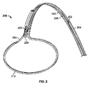
上述したように、ここで説明する閉鎖装置のスネアループアセンブリは1つ以上の標的組織を一時的に閉じるために、または制限するために、使用され得る。一般的に、スネアループアセンブリは、スネアと、縫合糸ループと、スネアと縫合糸ループとを少なくとも一時的に接合する保持部材とを備え得る。スネアループアセンブリはまた、後ほど詳述する1つ以上の減力縫合糸ロックを備えている。スネア(102)と、縫合糸ループ(104)と、保持部材(106)とを備えているスネアループアセンブリ(100)の一例証的変形例を図1に示す。スネアループアセンブリ(100)は、先端(110)を有する細長い本体(108)の中に少なくとも部分的に配置され得る。図1には、スネアループアセンブリ(100)が開構成において図示されており、細長い本体(104)の外に延出するスネアループアセンブリ(100)の部分は途切れのない開口を画定する。この開口は、スネアループアセンブリ(100)の1つ以上の構成要素(スネア等)によって画定され得、左心耳等の組織を取り囲むのに適し得る。一般的に、スネア(102)は、後ほど詳述するようにスネアループアセンブリ(100)を開きかつ閉じるために使用され得る。いくつかの例において、保持部材(106)は縫合糸ループ(104)とスネア(102)とを解放可能に結合するように構成され得、かつ縫合糸ループ(104)に十分な力がかかるとスネアループアセンブリ(100)から縫合糸ループ(104)を解放するように構成され得る。
(Snare loop assembly)
As described above, the snare loop assembly of the closure device described herein can be used to temporarily close or limit one or more target tissues. In general, a snare loop assembly may include a snare, a suture loop, and a retaining member that at least temporarily joins the snare and the suture loop. The snare loop assembly also includes one or more reduction suture locks that will be described in detail later. An illustrative variation of a snare loop assembly (100) comprising a snare (102), a suture loop (104), and a retaining member (106) is shown in FIG. The snare loop assembly (100) may be at least partially disposed within an elongated body (108) having a tip (110). In FIG. 1, the snare loop assembly (100) is shown in an open configuration, and the portion of the snare loop assembly (100) that extends out of the elongate body (104) defines an unbroken opening. This opening may be defined by one or more components (snare etc.) of the snare loop assembly (100) and may be suitable for surrounding tissue such as the left atrial appendage. In general, the snare (102) may be used to open and close the snare loop assembly (100) as will be described in detail later. In some examples, the retention member (106) may be configured to releasably couple the suture loop (104) and the snare (102) and when sufficient force is applied to the suture loop (104). It can be configured to release the suture loop (104) from the snare loop assembly (100).
(スネア)
スネアを備えているスネアループアセンブリの変形例において、スネアは、スネアループアセンブリを開構成と閉構成との間で変化させるように少なくとも部分的に可動であり得る。一般的に、スネアの一部分は細長い本体内に収容され得、スネアの別の部分は細長い本体の遠位端の外に延出し、スネアループアセンブリの開口を少なくとも部分的に画定し得る。いくつかの変形例において、スネアの一端は、閉鎖装置の1つ以上の部分に対し固定され、他端は細長い本体の中で前進または後退さrw得る。スネアの自由端の動きにより細長い本体の外に配置されるスネアループアセンブリの量は変化し、その結果、開口のサイズは変化し得る。具体的に、細長い本体の中でスネアを前進させるとスネアループアセンブリ開口のサイズは増加し得、スネアを後退させるとスネアループアセンブリ開口のサイズは減少し得、スネアループアセンブリは閉じ得る。スネアの自由端は、適切に操作され得る。いくつかの変形例において、スネアは、後ほど詳述するようにハンドルの1つ以上の部分に直接取り付けられ得る。別の変形例では、ハイポチューブ、ロッド、または他の剛体構造がスネアの自由端へ取り付けられ得る。この構造が、順に、ハンドルにより動かされることにより、細長い本体内でのスネアの前進または引き込みを容易にし得る。
(Snare)
In a variation of the snare loop assembly comprising a snare, the snare may be at least partially movable to change the snare loop assembly between an open configuration and a closed configuration. In general, a portion of the snare can be housed within the elongate body and another portion of the snare can extend out of the distal end of the elongate body and at least partially define an opening in the snare loop assembly. In some variations, one end of the snare may be secured to one or more portions of the closure device and the other end may be advanced or retracted rw within the elongated body. Movement of the free end of the snare changes the amount of snare loop assembly that is placed outside the elongate body so that the size of the opening can change. Specifically, when the snare is advanced within the elongated body, the size of the snare loop assembly opening can be increased, and when the snare is retracted, the size of the snare loop assembly opening can be decreased and the snare loop assembly can be closed. The free end of the snare can be manipulated appropriately. In some variations, the snare may be attached directly to one or more portions of the handle as will be described in detail later. In another variation, a hypotube, rod, or other rigid structure may be attached to the free end of the snare. This structure, in turn, can be moved by the handle to facilitate advancement or retraction of the snare within the elongated body.
閉鎖装置に対しスネアの一端が固定される変形例では、装置の適切な部分にスネアが固定され得る。例えば、いくつかの変形例では、スネアの一端が細長い本体の先端またはこれの近くに固定状態に保持され得る。別の変形例では、細長い本体の1つ以上の管腔内でスネアの固定端が添着される。さらに別の変形例では、スネアの固定端が、少なくとも一時的に装置のハンドルへ取り付けられ得る。スネアの一端は閉鎖装置に対し一時的に固定され得るが、この固定端を解放可能および/または移動可能に構成され得ることを理解されたい。解放可能および/または移動可能に構成されたスネアの固定端は数々の有用機能を果たし得る。場合によっては、一時的または永久的な装置の故障によりスネアの可動部分が行き詰ったりつっかえたりし得る。このような場合、スネアにより捕捉された組織を解放するには固定端を解放することが必要になることがある。他の例では、両端を使ってスネアを調整するために自由端を動かすことが望まれることがある。 In a variation where one end of the snare is secured to the closure device, the snare can be secured to an appropriate portion of the device. For example, in some variations, one end of the snare can be held fixed at or near the tip of the elongated body. In another variation, a fixed end of the snare is affixed within one or more lumens of the elongated body. In yet another variation, the fixed end of the snare may be attached at least temporarily to the handle of the device. It should be understood that one end of the snare can be temporarily secured to the closure device, but the secured end can be configured to be releasable and / or movable. A fixed end of a snare configured to be releasable and / or movable can serve a number of useful functions. In some cases, the moving parts of the snare can get stuck or replaced due to temporary or permanent device failure. In such cases, it may be necessary to release the fixed end to release the tissue captured by the snare. In other examples, it may be desirable to move the free end to adjust the snare using both ends.
スネアの一端が、細長い本体に対して一時的に固定されるように構成される場合、スネアのその端は、任意の好適な方式でその固定関係から解放され得る。例えば、いくつかの変形例では、スネアの一端が、壊れやすい部材によって固定様式で一時的に保持され得る。図16Aおよび16Bは、スネア(1600)の一端が、壊れやすい部材(1604)によって細長い本体(1602)に解放可能に固定され得る変形例を示す。具体的に、図16Aおよび16Bは、少なくとも1つの管腔(1605)を有する細長い本体(1602)の一部を示す。この変形例では、管腔(1605)の一部は、少なくとも第1および第2の副管腔(それぞれ(1606)および(1608)に分割され得る。図16Aに示されるように、第1の副管腔(1606)は、第1の断面積を有する第1の区域(1610)と、第2の断面積を有する第2の区域(1612)を有する。図16Aに示されるように、スネア(1600)の遠位端は、第1の副管腔1606)の第1の区域(1610)に設置され得、壊れやすい部材(1604)の遠位端に取り付けられ得る。壊れやすい部材(1604)は、第1の副管腔(1606)の第2の区域(1612)および管腔(1605)を通過し得る。 If one end of the snare is configured to be temporarily secured relative to the elongate body, that end of the snare can be released from its securing relationship in any suitable manner. For example, in some variations, one end of the snare can be temporarily held in a fixed manner by a frangible member. 16A and 16B show a variation where one end of the snare (1600) can be releasably secured to the elongate body (1602) by a frangible member (1604). Specifically, FIGS. 16A and 16B show a portion of an elongated body (1602) having at least one lumen (1605). In this variation, a portion of the lumen (1605) may be divided into at least first and second sub-lumens (respectively (1606) and (1608). As shown in FIG. 16A, the first The secondary lumen (1606) has a first area (1610) having a first cross-sectional area and a second area (1612) having a second cross-sectional area, as shown in Figure 16A. The distal end of (1600) may be placed in the first section (1610) of the first secondary lumen 1606) and attached to the distal end of the frangible member (1604). Fragile member (1604) may pass through second region (1612) and lumen (1605) of first secondary lumen (1606).
壊れやすい部材(1604)へのスネア(1600)の取着は、定位置にスネア(1600)の遠位端を一時的に係止するのに役立ち得る。壊れやすい部材(1604)の近位端(図示せず)は、装置ハンドル(図示せず)の1つ以上の部分に固定する様式で、一時的に取り付けられ得る。壊れやすい部材(1604)の近位端が、定位置に保持されるので、壊れやすい部材(1604)は、スネアが細長い本体(1602)の遠位端から外に遠位方向に引き込まれるのを阻止し得る。加えて、第1の区域(1610)の断面積は、スネア(1600)の遠位端が第2の区域(1612)内に第1の区域(1610)を通過できないように、第2の区域(1612)の断面積と異なり得る。このようにして、スネア(1600)は、細長い本体(1602)内に近位方向に移動するのを阻止され得る。加えて、いくつかの変形例では、スネア(1600)および第1の区域(1610)の少なくとも一部は、第1の区域(1610)内に収容されるスネア(1600)が、第1の区域(1610)に対して回転することが不可能であり得るように、非円形の断面積(例えば、楕円形、三角形、正方形、多角形、または不規則形状を伴う形)を有し得る。スネア(1600)の遠位端が、近位方向、遠位方向に移動、または副管腔(1606)の第1の区域(1610)に対して回転するのを阻止されるので、スネアの遠位端が、細長い本体(1602)に対して効果的に静止させられ得る。 Attachment of the snare (1600) to the frangible member (1604) may help temporarily lock the distal end of the snare (1600) in place. The proximal end (not shown) of the frangible member (1604) may be temporarily attached in a manner that secures to one or more portions of the device handle (not shown). Since the proximal end of the fragile member (1604) is held in place, the fragile member (1604) prevents the snare from being pulled distally out of the distal end of the elongated body (1602). Can be blocked. In addition, the cross-sectional area of the first area (1610) is such that the distal end of the snare (1600) cannot pass through the first area (1610) within the second area (1612). It may be different from the cross-sectional area of (1612). In this way, the snare (1600) can be prevented from moving proximally into the elongate body (1602). In addition, in some variations, at least a portion of the snare (1600) and the first area (1610) is a portion of the snare (1600) housed within the first area (1610). It may have a non-circular cross-sectional area (eg, a shape with an ellipse, triangle, square, polygon, or irregular shape) so that it may not be possible to rotate relative to (1610). Since the distal end of the snare (1600) is prevented from moving proximally, distally, or rotating relative to the first section (1610) of the secondary lumen (1606), The distal end can be effectively stationary relative to the elongated body (1602).
壊れやすい部材(1604)は、壊れやすい部材(1604)に十分な力がかかると壊れやすい部材(1604)とスネア(1600)との取り付けが破断するように構成される。スネア(1600)をその固定位置から解放するために、ユーザは壊れやすい部材(1604)の近位端を直接的にまたは間接的に(例えば、1つ以上のハンドル構成要素を介して)引いてもよい。スネア(1600)が近位方向に動いて第2の区域(1612)の中に入ることが阻止されるので、壊れやすい部材(1604)に十分な近位方向の力がかかると壊れやすい部材(1604)とスネア(1600)との係合は破断し、結果的には図16Bに見られるようにスネア(1600)は解放され得る。 The fragile member (1604) is configured such that attachment of the fragile member (1604) and snare (1600) is broken when sufficient force is applied to the fragile member (1604). To release the snare (1600) from its locked position, the user pulls the proximal end of the frangible member (1604) directly or indirectly (eg, via one or more handle components). Also good. The snare (1600) is prevented from moving proximally into the second zone (1612) so that the fragile member (1604) is subject to a fragile member (1604) when a sufficient proximal force is applied. 1604) and the snare (1600) are broken, resulting in the snare (1600) being released as seen in FIG. 16B.
ここで説明するスネアは何らかの適当な材料で、あるいは材料の組み合わせで作られ得る。例えば、いくつかの変形例において、スネアは、形状記憶合金(例えば、ニッケルチタン合金等)等の形状記憶材料で作られ得、あるいはステンレス鋼、ポリエステル、ナイロン、ポリエチレン、ポリプロピレン、これらの組み合わせ等で作られ得る。スネアが形状記憶材料から作られる変形例において、スネアは、スネアループアセンブリが開構成に設定されるときに特定の形状または構成をおびるよう構成され得るが、スネアループアセンブリを閉構成に設定する際には少なくとも部分的に細長い本体の中に引き込まれ得る。例えば、前述の図1に見られるように、スネア(102)はスネアループアセンブリ(100)が開構成に設定されるときに概ね円形の輪を形成し得る。図1には概ね円形のものが図示されているが、スネア(102)は任意の形の輪を形成し得る。いくつかのスネア構造を図17A〜17Dに示す。図17Aに見られる変形例で、スネア(1700)は展開構成のときに涙滴形の輪(1702)を形成し得る。図17Bに見られる変形例で、スネア(1704)は展開構成のときに楕円形または長円形の輪(1706)を形成し得る。図17Cに見られる変形例で、スネア(1708)は展開構成のときに概ね三角形の輪(1709)をなし得る。さらにいくつかの変形例では、細長い本体に対しスネアループに角度を付け得る。例えば、図17Dに示す閉鎖装置(1710)の側面図で、スネア(1712)は、細長い本体の縦軸(1716)に対し一定の角度(θ)で細長い本体(1714)から出る。この角度(θ)は何らかの適当な角度でよい。例えば、角度(θ)は、約5°、約15°、約30°、約45°、約60°、約75°、約90°、約40°〜約50°、約35°〜約55°、約30°〜約60°等でよい。角度を付けることで、身体内で閉鎖装置が動かされるときに組織に対しスネア(1712)を位置決めしやすくなり得るので、細長い本体(1714)に対し角度が付いたスネア(1712)はスネア(1712)で組織を捕捉するのに役立ち得る。 The snare described herein can be made of any suitable material or combination of materials. For example, in some variations, the snare can be made of a shape memory material such as a shape memory alloy (eg, nickel titanium alloy), or in stainless steel, polyester, nylon, polyethylene, polypropylene, combinations thereof, and the like. Can be made. In variations where the snare is made from a shape memory material, the snare may be configured to assume a particular shape or configuration when the snare loop assembly is set to an open configuration, but when setting the snare loop assembly to a closed configuration Can be at least partially retracted into the elongated body. For example, as seen in FIG. 1 above, the snare (102) may form a generally circular ring when the snare loop assembly (100) is set to an open configuration. Although shown in FIG. 1 as being generally circular, the snare (102) may form any shape of ring. Some snare structures are shown in FIGS. In the variation seen in FIG. 17A, the snare (1700) may form a teardrop shaped ring (1702) when deployed. In the variation seen in FIG. 17B, the snare (1704) may form an oval or oval ring (1706) when in the deployed configuration. In the variation seen in FIG. 17C, the snare (1708) may form a generally triangular ring (1709) when in the deployed configuration. Further, in some variations, the snare loop may be angled relative to the elongated body. For example, in a side view of the closure device (1710) shown in FIG. 17D, the snare (1712) exits the elongated body (1714) at a constant angle (θ) relative to the longitudinal axis (1716) of the elongated body. This angle (θ) may be any suitable angle. For example, the angle (θ) is about 5 °, about 15 °, about 30 °, about 45 °, about 60 °, about 75 °, about 90 °, about 40 ° to about 50 °, about 35 ° to about 55. °, about 30 ° to about 60 °, etc. The angled snare (1712) with respect to the elongate body (1714) can be more easily positioned with respect to the tissue when the closure device is moved within the body, so ) Can help to capture tissue.
スネア(1800)のさらに別の変形例を図18A〜18Dに示す。この変形例において、スネア(1800)は、スネア(1800)が開構成で細長い本体(1804)から延出するときにフック形状の輪(1802)を形成し得る。図18Aはスネア(1800)の斜視図を示しており、18Bはスネア(1800)の側面図を示している。輪(1802)は折れ曲がってフック形状を形成するので(図18Bの側面図で強調)、スネア(1800)は、開構成のときに身体組織間にスペースを作るのに役立ち得る。例えば、図18Cに見られるように、心膜腔内で開いたスネア(1800)は心臓(1808)から心膜(1806)を持ち上げ得る。心膜内にスペースができると、図18Dに見られるように左心耳(1810)等の組織をスネア(1800)で捕捉することが容易になり得る。 Yet another variation of the snare (1800) is shown in FIGS. In this variation, the snare (1800) may form a hook-shaped ring (1802) when the snare (1800) extends from the elongated body (1804) in an open configuration. 18A shows a perspective view of the snare (1800) and 18B shows a side view of the snare (1800). Since the annulus (1802) folds to form a hook shape (highlighted in the side view of FIG. 18B), the snare (1800) can help create space between body tissues when in the open configuration. For example, as seen in FIG. 18C, an open snare (1800) within the pericardial cavity can lift the pericardium (1806) from the heart (1808). The space in the pericardium can facilitate the capture of tissue such as the left atrial appendage (1810) with the snare (1800) as seen in FIG. 18D.
(縫合糸ループ)
ここで説明するスネアループアセンブリはまた、組織を閉じた状態に保つ縫合糸ループを備え得る。一般的に縫合糸ループは、例えば、後ほど詳述するように保持部材により、スネアへ解放可能に取り付けられ得る。さらに、縫合糸ループは縫合糸の結び目を備え得るが、必ずしも縫合糸の結び目を備えているとは限らない。この縫合糸の結び目は、引き結び(一方向引き結び等)を含むがこれに限定されない、何らかの適当な結び目でよい。いくつかの変形例では、後ほど詳述するように結び目の少なくとも一部分は細長い本体の先端の中で保持され得る。別の変形例では、後ほど詳述するように縫合糸の結び目が細長い本体に対し固定関係で一時的に保持され得る。
(Suture loop)
The snare loop assembly described herein may also include a suture loop that keeps the tissue closed. In general, the suture loop may be releasably attached to the snare, for example, by a retaining member as will be described in detail later. Further, the suture loop may comprise a suture knot, but not necessarily a suture knot. The suture knot may be any suitable knot, including but not limited to a pull knot (such as a one-way pull knot). In some variations, at least a portion of the knot can be retained within the tip of the elongated body, as will be described in detail later. In another variation, the suture knot may be temporarily held in a fixed relationship to the elongated body, as will be described in detail later.
縫合糸ループが引き結びを備えている変形例では、引き結びを通して縫合糸を前進させるかまたは引き込むことにより縫合糸ループの大きさは変化し得る。縫合糸の結び目が細長い本体の先端に保持される場合は、縫合糸ループの大きさが変化しても縫合糸の結び目は動かない場合がある。後ほど詳述するように、これは閉鎖装置が組織を損傷するのを防ぐのに役立ち得る。 In variations where the suture loop includes a knot, the size of the suture loop can be changed by advancing or retracting the suture through the knot. If the suture knot is held at the tip of the elongated body, the suture knot may not move even if the size of the suture loop changes. As will be detailed later, this can help prevent the closure device from damaging the tissue.
いくつかの変形例において、縫合糸ループは単方向係止構造をさらに備えている。これらの変形例において、単方向係止構造は、縫合糸に沿って一方向に前進させることができ、ただし第2の方向での動きには逆らうことができる、任意の構造であり得る。これらの変形例において、係止構造は縫合糸ループの一部分にわたって前進させ得、縫合糸の結び目を定位置に係止するのに役立つ。例えば、いくつかの変形例において、単方向係止構造は、縫合糸を少なくとも部分的に取り囲むビードまたは機械構造を備え得る。これらの変形例において、ビードは1つ以上の歯または突起を備え得、歯または突起は、縫合糸に沿って一方向にビードが前進することを許すが、反対方向での動きは阻止するか、あるいは反対方向の動きに逆らう。係止構造は、ここで説明する閉鎖装置のいずれかひとつにより前進させられ得、あるいは縫合糸ループが閉鎖装置から解放された後に独立した装置により前進させられ得る。 In some variations, the suture loop further comprises a unidirectional locking structure. In these variations, the unidirectional locking structure can be any structure that can be advanced in one direction along the suture, but that can resist movement in the second direction. In these variations, the locking structure can be advanced over a portion of the suture loop to help lock the suture knot in place. For example, in some variations, the unidirectional locking structure may comprise a bead or mechanical structure that at least partially surrounds the suture. In these variations, the bead may comprise one or more teeth or protrusions that allow the bead to advance in one direction along the suture but prevent movement in the opposite direction? Or counter the movement in the opposite direction. The locking structure can be advanced by any one of the closure devices described herein, or it can be advanced by an independent device after the suture loop is released from the closure device.
縫合糸ループは締出しまたは閉鎖に役立つ何らかの適当な材料から作られ得る。例えば、これは、生分解性材料(例えば、ポリ乳酸、ポリグリコール酸、ポリラクティックコグリコリック酸等)から作られ得、あるいは非生分解性材料(例えば、金属、スチール、ポリエステル、ナイロン、プロピレン、絹、これらの組み合わせ等)から作られ得る。 The suture loop may be made from any suitable material that aids in squeezing or closing. For example, it can be made from a biodegradable material (eg, polylactic acid, polyglycolic acid, polylactic coglycolic acid, etc.) or a non-biodegradable material (eg, metal, steel, polyester, nylon, Propylene, silk, combinations thereof, etc.).
組織を閉じるため縫合糸ループが締められると、縫合糸ループの縫合糸の結び目に組織が引き込まれる可能性があり得る。あまりにも多くの組織が縫合糸の結び目に引き込まれると縫合糸の結び目がつかえ、縫合糸ループをさらに締めることができなくなり得る。いくつかの変形例において、縫合糸ループは、縫合糸の結び目の一部分を遮蔽するために、1つ以上のプレジェットまたは管部分を備え得る。結び目遮蔽要素を備えている縫合糸ループの変形例を図19A〜19Gに示す。図19Aでは、縫合糸ループ(1900)の2本の脚がプレジェット(1902)の中に通されている。本明細書で述べられる装置で使用されるプレジェットは、例えば、ポリウレタンフォーム、フェルト、テフロン(登録商標)布、ダクロン、コラーゲン等、何らかの適当な材料から作られ得る。図19Bに見られる縫合糸ループ(1904)の別の変形例では、プレジェット(1905)が折り畳まれ、その中に縫合糸ループ(1904)の2本の脚が通されている。縫合糸の結び目(1906)と組織(図示せず)との間に配置されるプレジェット(1905)の厚みを増すことにより、プレジェット(1905)は、縫合糸の結び目(1906)に引き込まれる組織の量をさらに減らし得る。図19Cに見られるプレジェット(1910)を備えている縫合糸ループ(1908)のさらに別の変形例では、プレジェット(1910)の一部分のみ折り畳まれている。この変形例では、縫合糸ループ(1908)の一方の脚(1912)がプレジェット(1910)の折り返された部分に通されており、他方の脚はプレジェット(1910)の単層部分に通され得る。 When the suture loop is tightened to close the tissue, the tissue may be drawn into the suture loop's suture knot. If too much tissue is drawn into the suture knot, the suture knot may catch and the suture loop cannot be tightened further. In some variations, the suture loop may include one or more pledgets or tube portions to shield a portion of the suture knot. A variation of a suture loop with a knot shielding element is shown in FIGS. In FIG. 19A, the two legs of the suture loop (1900) are threaded through the pledget (1902). The pledgets used in the devices described herein can be made from any suitable material, such as, for example, polyurethane foam, felt, Teflon cloth, Dacron, collagen, and the like. In another variation of the suture loop (1904) seen in FIG. 19B, the pledget (1905) is folded through which the two legs of the suture loop (1904) are threaded. By increasing the thickness of the pledget (1905) disposed between the suture knot (1906) and tissue (not shown), the pledget (1905) is drawn into the suture knot (1906). The amount of tissue can be further reduced. In yet another variation of suture loop (1908) with pledget (1910) seen in FIG. 19C, only a portion of pledget (1910) is folded. In this variation, one leg (1912) of the suture loop (1908) is threaded through the folded portion of the pledget (1910) and the other leg is threaded through the single layer portion of the pledget (1910). Can be done.
図19Dに見られる縫合糸ループ(1914)のさらに別の変形例では、縫合糸ループ(1914)の一方の脚(1916)と縫合糸ループ(1914)の自由端(1918)がプレジェット(1920)に通されている。図19Eに見られる縫合糸ループ(1922)の変形例では、縫合糸ループ(1922)の両脚と自由端(1924)がプレジェット(1926)に通されている。これらの変形例で、細長い本体の1つ以上の部分、管腔、または凹所にフィットする大きさにプレジェット(1926)の1つ以上の部分を形成もしくは構成され得ることを理解されたい。図19Fに見られる縫合糸ループ(1928)の変形例では、縫合糸の結び目(1930)が管(1932)によって少なくとも部分的に遮蔽される。この変形例で、縫合糸ループ(1928)の脚は管(1932)の両端を通過し得、縫合糸の結び目(1930)は管(1932)の側部の開口部(1934)から外に出ていてもよい。図19Gに見られる縫合糸ループ(1936)の別の変形例では、縫合糸の結び目(図示せず)が管(1938)によって遮蔽される。この変形例では、縫合糸ループ(1936)の脚が管(1938)の側部の溝穴(1940)から外に出ており、縫合糸ループ(1936)の自由端は管(1938)の一端から外に出ていてもよい。 In yet another variation of the suture loop (1914) seen in FIG. 19D, one leg (1916) of the suture loop (1914) and the free end (1918) of the suture loop (1914) are connected to the pledget (1920). ). In the variation of suture loop (1922) seen in FIG. 19E, both legs and free end (1924) of suture loop (1922) are threaded through pledget (1926). It should be understood that in these variations, one or more portions of the pledget (1926) may be formed or configured to fit in one or more portions, lumens, or recesses of the elongated body. In the variation of the suture loop (1928) seen in FIG. 19F, the suture knot (1930) is at least partially shielded by the tube (1932). In this variation, the leg of the suture loop (1928) can pass through the ends of the tube (1932) and the suture knot (1930) exits from the opening (1934) on the side of the tube (1932). It may be. In another variation of the suture loop (1936) seen in FIG. 19G, a suture knot (not shown) is shielded by a tube (1938). In this variation, the leg of the suture loop (1936) protrudes out of the slot (1940) on the side of the tube (1937) and the free end of the suture loop (1936) is the end of the tube (1937). You may have gone out from.
(保持部材)
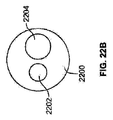
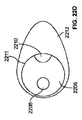
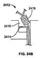
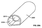
ここで説明する装置に使用され得る例証的保持部材を図20A〜20Cに示す。図20Aに見られる保持部材(2014)の端面図で、保持部材(2014)は閉鎖要素と縫合糸ループとを保持する第1および第2の管腔(2016、2018)を有する。この変形例で、第2の管腔(2018)はその長さに沿って細隙または他の開口部(2020)を有し、展開される縫合糸をここに通すことができる。勿論、第1および第2の管腔を互いに適切に配置または配向でき、また同様に、第2の管腔の細隙または他の開口部を第1の管腔に対し適切に配置または配向され得ることを理解されたい(例えば、これは、第1の管腔(2016)から約180°、約150°、約120°、約90°、約60°、約30°等であり得る)。図20Bは、第1の管腔(2022)と、第2の管腔(2024)と、細隙(2026)とを有する保持部材の図解を提供している。この変形例で、細隙(2026)は図20Aの細隙より第1の管腔(2022)の近くに配置されている。細隙開口部の幅または間隔は、任意に、あるいは適切に、選択され得る。同様に、細隙は、必ずしも保持部材の全長に沿って延在するとは限らない、あるいは必ずしも保持部材の全長に沿って連続するとは限らない。いくつかの変形例において、細隙は、縫合糸を捕捉しかつ保持するために、その長さに沿ってプロングまたはアームを有し得る。別の変形例において、細隙は、縫合糸を留めるために、あるいは保持するために、一時的に使用される生分解性ポリマーにより、間隔を置いて覆われ得る。勿論、さらに別の変形例においては、保持部材は細隙を備えず、代わりに、上述したプロングや鋲等、タイプの異なる保持機構を備えている。さらに別の変形例では、保持部材に細隙や開口部はなく、縫合糸ループは、保持部材を除去または引き込んで装置を閉じるときに解放される。
(Holding member)
Illustrative retaining members that can be used in the devices described herein are shown in FIGS. In the end view of retention member (2014) seen in FIG. 20A, retention member (2014) has first and second lumens (2016, 2018) that retain closure elements and suture loops. In this variation, the second lumen (2018) has a slit or other opening (2020) along its length through which the deployed suture can pass. Of course, the first and second lumens can be properly positioned or oriented with respect to each other, and similarly, the second lumen slit or other opening can be properly positioned or oriented with respect to the first lumen. It should be understood that (eg, this may be about 180 °, about 150 °, about 120 °, about 90 °, about 60 °, about 30 °, etc. from the first lumen (2016)). FIG. 20B provides an illustration of a retention member having a first lumen (2022), a second lumen (2024), and a slit (2026). In this variation, the slit (2026) is located closer to the first lumen (2022) than the slit of FIG. 20A. The width or spacing of the slit openings can be selected arbitrarily or appropriately. Similarly, the slit does not necessarily extend along the entire length of the holding member, or does not necessarily continue along the entire length of the holding member. In some variations, the slit may have prongs or arms along its length to capture and hold the suture. In another variation, the slits may be spaced apart by a biodegradable polymer that is temporarily used to fasten or hold the suture. Of course, in yet another modification, the holding member does not have a slit, but instead has different types of holding mechanisms such as the above-mentioned prongs and scissors. In yet another variation, the retaining member has no slits or openings and the suture loop is released when the retaining member is removed or retracted to close the device.
図20Cは、保持部材の別の変形例を提供する。この変形例で、保持部材は、第1の管腔(2028)と、第2の管腔(2030)と、分離領域(2032)とを有する。分離領域は、何らかの適当な方法で構成され得る。例えば、分離領域は、力がかかることにより穿孔し縫合糸を解放するように構成された穿孔領域を備え得る。代替えとして、分離領域は、壊れて縫合糸を解放するように構成され得る、薄い壁からなり得、あるいはタイプの異なる、脆弱領域であり得る。保持部材が何らかの適当な形状または形を有し、また何らかの適当な材料から作られ得ることを理解されたい。同様に、管腔は必ずしも完全な円であるとは限らず、また必ずしも円形の断面形状を有するとは限らない。これらの保持部材やタイプの異なる保持部材が使用される場合、縫合糸ループは、適切に配置され締められた後、保持部材から引き離される、引き出されるか、または別様に解放され得る。 FIG. 20C provides another variation of the retaining member. In this variation, the retaining member has a first lumen (2028), a second lumen (2030), and a separation region (2032). The separation region can be configured in any suitable manner. For example, the separation region may comprise a perforation region configured to perforate and release the suture upon application of force. Alternatively, the separation region may consist of a thin wall, which may be configured to break and release the suture, or may be a fragile region of a different type. It should be understood that the retaining member can have any suitable shape or shape and can be made from any suitable material. Similarly, a lumen is not necessarily a perfect circle and does not necessarily have a circular cross-sectional shape. When these holding members or different types of holding members are used, the suture loop may be pulled away, pulled out, or otherwise released after being properly placed and tightened.
(細長い本体)
上で簡単に述べたように、ここで説明する閉鎖装置の細長い本体は、スネアループアセンブリの遠位端とハンドルまたは作動機構とを接続し得、依然として、細長い本体を通してスネアループアセンブリの制御を可能にする。具体的に、スネアループアセンブリの構成要素の少なくとも一部分は細長い本体の中に収容され得、細長い本体を通してハンドルへ接続され得る。いくつかの変形例において、細長い本体の少なくとも一部分は可撓性であり得、これにより組織における細長い本体の移動は容易になり得る。
(Elongated body)
As briefly mentioned above, the elongate body of the closure device described herein can connect the distal end of the snare loop assembly to a handle or actuation mechanism and still allow control of the snare loop assembly through the elongate body. To. Specifically, at least a portion of the components of the snare loop assembly may be housed within the elongated body and connected to the handle through the elongated body. In some variations, at least a portion of the elongate body can be flexible, which can facilitate movement of the elongate body in tissue.
ここで説明する閉鎖装置との使用に好適な細長い本体の一例証的変形例を図21に示す。そこには、ハンドル部分(2102)へ取り付けられた細長い本体(2100)が見られる。細長い本体(2100)は、先端部分(2103)と、湾曲部(2104)と、第1の管腔(2106)と、第2の管腔(2108)と、第3の管腔(2110)とを備え得る。図21には単一の湾曲部(2104)を有するものが図示されているが、細長い本体(2100)は、湾曲部を有さないこともあれば、細長い本体(2100)の各部分に多数の湾曲部を有することもある。さらに、いくつかの変形例において、閉鎖装置は、細長い本体(2100)の形を変える働きをし得る1つ以上の機構を備えている。細長い本体(2100)が1つ以上の湾曲部(2104)を備えている場合は、細長い本体を一時的に真っすぐに伸ばすために、管、心棒、または他の伸展機構(図示せず)が使用され得る。例えば、細長い本体(2100)の1つ以上の管腔内に剛体の管または心棒が設置され得、これが湾曲した部分を一時的に真っすぐに伸ばし得る。送達時(例えば、左心耳に使用される場合なら心膜腔に到達する前)は真っすぐに伸ばされ得、伸展機構が引き込まれ得ると細長い本体(2100)は元の構成に戻る。伸展機構は何らかの適当な材料で作られ得る(例えば、硬質プラスチック、ステンレス鋼、これらの組み合わせ等)。 An illustrative variation of an elongated body suitable for use with the closure device described herein is shown in FIG. There is seen an elongated body (2100) attached to the handle portion (2102). The elongate body (2100) includes a tip portion (2103), a bend (2104), a first lumen (2106), a second lumen (2108), and a third lumen (2110). Can be provided. Although FIG. 21 illustrates one having a single bend (2104), the elongate body (2100) may or may not have a bend, and multiple portions of the elongate body (2100) may be provided. It may have a curved part. Further, in some variations, the closure device includes one or more mechanisms that can serve to change the shape of the elongated body (2100). If the elongate body (2100) includes one or more bends (2104), a tube, mandrel, or other extension mechanism (not shown) is used to temporarily elongate the elongate body. Can be done. For example, a rigid tube or mandrel can be placed in one or more lumens of the elongate body (2100), which can temporarily straighten a curved portion. Upon delivery (eg, before reaching the pericardial space if used for the left atrial appendage), the elongate body (2100) returns to its original configuration when the extension mechanism can be retracted. The extension mechanism can be made of any suitable material (eg, hard plastic, stainless steel, combinations thereof, etc.).
別の変形例では、あらかじめ曲げられた1つ以上の管または心棒を細長い本体(2100)の中に挿入することで、1つ以上の湾曲した部分を作り得る。さらに別の変形例では、細長い本体(2100)内、細長い本体(2100)上、または細長い本体(2100)の周囲に、1つ以上のプルワイヤが配置され得、1つ以上のプルワイヤが引かれるか、押されるか、または別様に操られると、細長い本体(2100)は撓むか、または曲がり得る。ここで説明する装置が操縦性のため構成され得ること、あるいはロボット用に構成(例えば、1つ以上のロボット装置または別様に自動装置用に構成)され得ることは、理解されたい。 In another variation, one or more curved portions may be created by inserting one or more pre-bent tubes or mandrels into the elongate body (2100). In yet another variation, one or more pull wires can be disposed within, on, or around the elongate body (2100), or can the one or more pull wires be pulled? When pushed, or otherwise manipulated, the elongate body (2100) can flex or bend. It should be understood that the devices described herein can be configured for maneuverability, or can be configured for a robot (eg, configured for one or more robotic devices or otherwise automated devices).
(管腔)
ここで説明する細長い本体は、適当数の管腔を有し得る。ここで用語「管腔」が使われる場合、それは、細長い本体または閉鎖装置の他の部分の中に延在する穴または通路を表すため使われていることを理解されたい。管腔が必ずしも全面的に密閉されるとは限らないことを理解されたい(つまり管腔は、その長さの一部または全部にわたって1つ以上の溝穴、細隙、間隙、または他の開口部を備えていることがある)。細長い本体は1つ、2つ、3つ、4つ、または5つ以上の管腔を備えていることがある。いくつかの管腔が、あるいは全ての管腔が、細長い本体の全体にわたって延在することがある(すなわち細長い本体の近位端から細長い本体の遠位端まで)。他の管腔は、細長い本体の一部分の中だけを通過することもある(例えば、細長い本体沿いの一端から中間点まで通過、あるいは細長い本体沿いの2つの中間点の間を通過)。例えば、図21に見られる変形例で、第3の管腔(2110)は細長い本体(2100)の長さに沿って細長い本体(2100)の近位端から中間点まで通っている。この変形例では、1つ以上のガイドワイヤ、視覚化装置、または作業装置(図示せず)を、第3の管腔(2110)の中に通し得る。
(Lumen)
The elongated body described herein may have any suitable number of lumens. It should be understood that where the term “lumen” is used herein, it is used to describe a hole or passage that extends into the elongate body or other portion of the closure device. It should be understood that a lumen is not necessarily completely sealed (ie, a lumen can have one or more slots, slits, gaps, or other openings throughout some or all of its length. May have a part). The elongate body may comprise one, two, three, four, five or more lumens. Some lumens, or all lumens, may extend throughout the elongated body (ie, from the proximal end of the elongated body to the distal end of the elongated body). Other lumens may only pass through a portion of the elongate body (eg, from one end along the elongate body to the midpoint, or between two midpoints along the elongate body). For example, in the variation seen in FIG. 21, the third lumen (2110) passes along the length of the elongated body (2100) from the proximal end of the elongated body (2100) to the midpoint. In this variation, one or more guidewires, visualization devices, or working devices (not shown) may be passed through the third lumen (2110).
スネアループアセンブリの種々の構成要素は、細長い本体の管腔の中に収容され得る。例えば、いくつかの変形例では、1本の管腔内にスネアループアセンブリの全構成要素が収容され得る。別の変形例では、スネアループアセンブリの異なる部分が少なくとも部分的に別々の管腔内に収容され得る。例えば、いくつかの変形例において、細長い本体は少なくとも2つの管腔を備え得る。これらの変形例では、縫合糸ループの自由端が第1の管腔を通ってハンドル部分に至り、スネアの自由端は第2の管腔を通ってハンドル部分に至る。後ほど詳述するように、縫合糸ループの余分な縫合糸が細長い本体の中に収容される変形例では、この余分な縫合糸が適切な管腔内に収容され得る。例えば、いくつかの変形例において、余分な縫合糸は、縫合糸ループの自由端と同じ管腔内に、あるいはスネアの自由端と同じ管腔内に、あるいはまったく異なる管腔内に、収容され得る。 Various components of the snare loop assembly may be housed within the lumen of the elongate body. For example, in some variations, all components of the snare loop assembly may be housed within a single lumen. In another variation, different portions of the snare loop assembly may be housed at least partially within separate lumens. For example, in some variations, the elongate body can comprise at least two lumens. In these variations, the free end of the suture loop passes through the first lumen to the handle portion and the free end of the snare passes through the second lumen to the handle portion. As will be described in more detail below, in variations where excess suture of the suture loop is housed within the elongate body, this excess suture can be housed within a suitable lumen. For example, in some variations, excess suture is housed in the same lumen as the free end of the suture loop, in the same lumen as the free end of the snare, or in a completely different lumen. obtain.
いくつかの変形例では、細長い本体の1つ以上の管腔が少なくとも部分的に1つ以上の副管腔に分割され得る。具体的に、管腔は、管腔の長さの一部分に沿って2つ以上の副管腔に分割され得る。これらの変形例では、管腔を2つ以上の副管腔に分割するため分離管が使用され得る。ここで説明する閉鎖装置との使用に好適な分離管のいくつかの変形例を図22A〜22Dに示す。具体的に、図22Aおよび22Bは分離管(2200)の一変形例の斜視図と上面図とをそれぞれ示している。この変形例で、分離管(2200)はその中に延在する第1(2202)および第2(2204)の管腔を備え得る。細長い本体(図示せず)の管腔の内側に設置された分離管(2200)の第1(2202)および第2(2204)の管腔は、細長い本体の管腔の中で副管腔として機能し得る。分離管(2200)により、1本の管腔から細長い本体の一部分に沿って1本の通路ができ、さらに細長い本体の別の部分に沿って2本以上の独立した通路ができ得る。 In some variations, one or more lumens of the elongate body may be at least partially divided into one or more secondary lumens. Specifically, the lumen may be divided into two or more secondary lumens along a portion of the lumen length. In these variations, a separation tube may be used to divide the lumen into two or more secondary lumens. Some variations of separation tubes suitable for use with the closure devices described herein are shown in FIGS. Specifically, FIGS. 22A and 22B respectively show a perspective view and a top view of a variation of the separation tube (2200). In this variation, the separation tube (2200) may comprise first (2202) and second (2204) lumens extending therein. The first (2202) and second (2204) lumens of the separation tube (2200) placed inside the lumen of the elongated body (not shown) are secondary lumens within the lumen of the elongated body. Can function. Separation tube (2200) may allow one passage along a portion of the elongated body from one lumen and two or more independent passages along another portion of the elongated body.
図22Aおよび22Bでは、2つの管腔((2202)および(2204))を有するものが図示されているが、分離管(2200)が適当数(例えば、1つ、2つ、3つ、または4つ以上)の管腔を含み得ることを理解されたい。このようにして、細長い本体の管腔は、分離管の長さに沿って適当数の副管腔に分割され得る。尚、いくつかの変形例においては、分離管はその中を通過する1本の管腔のみ有し得ることを理解されたい。これらの変形例において、分離管は管腔を複数の副管腔に分割しないが、代わりに、管腔の一部分に沿って管腔のサイズおよび/または形を変化させ得る。また、分離管(2200)のいくつかの管腔が、あるいは全ての管腔が、分離管の一部分のみ通過する場合もあることを理解されたい。 In FIGS. 22A and 22B, one having two lumens ((2202) and (2204)) is illustrated, but an appropriate number of separation tubes (2200) (eg, one, two, three, or It should be understood that four or more) lumens may be included. In this manner, the lumen of the elongated body can be divided into an appropriate number of secondary lumens along the length of the separation tube. It should be understood that in some variations, the separation tube may have only one lumen passing therethrough. In these variations, the separation tube does not divide the lumen into a plurality of secondary lumens, but may instead vary the lumen size and / or shape along a portion of the lumen. It should also be understood that some lumens of the separation tube (2200) or all lumens may pass through only a portion of the separation tube.
別の変形例において、分離管は1つ以上の溝または経路を含み得る。これらの溝または経路は、細長い本体の管腔の内側に設置されたときに完全に密閉された副管腔を形成し得る。例えば、分離管(2206)の一変形例を図22Cおよび22Dに示す。具体的に、図22Cに見られる分離管(2206)の斜視図で、分離管(2206)は、管腔(2208)を備え、かつその外面に沿って経路(2210)を備えている。図22Dの上面図に見られるように細長い本体(2212)の管腔(2211)の内側に分離管(2206)が設置されると、経路(2210)は、部分的に分離管(2206)により画定されかつ部分的に管腔壁により画定され得る、密閉された管腔を形成し得る。ここで説明する分離管が、適当数の経路および/または管腔を備えていること、また経路および/または管腔の適当な組み合わせを備えていることは、理解されたい。 In another variation, the separation tube may include one or more grooves or channels. These grooves or pathways can form a completely sealed secondary lumen when placed inside the lumen of the elongated body. For example, a variation of the separation tube (2206) is shown in FIGS. 22C and 22D. Specifically, in the perspective view of the separation tube (2206) seen in FIG. 22C, the separation tube (2206) includes a lumen (2208) and a path (2210) along its outer surface. When the separation tube (2206) is placed inside the lumen (2211) of the elongated body (2212) as seen in the top view of FIG. 22D, the path (2210) is partially routed by the separation tube (2206). A sealed lumen can be formed that can be defined and partially defined by the lumen wall. It should be understood that the separation tube described herein includes an appropriate number of pathways and / or lumens, and an appropriate combination of pathways and / or lumens.
いくつかの変形例においては、分離管を通してスネアループアセンブリの1つ以上の構成要素を解放できるよう分離管を構成することが望まれ得る。例えば、いくつかの例では、後ほど詳述するように、分離管の一区間の2つ以上の管腔/経路の中に縫合糸ループの一部分を通し得る。装置から縫合糸ループを解放するには、縫合糸ループをはずしたりちぎったりせずに分離管から余分な縫合糸を取り除く必要があり得る。そこでいくつかの変形例においては、分離管は、2つ以上の管腔、経路、またはこれらの組み合わせの間に1つ以上の分離領域(図示せず)を備え得る。保持部材について上述したように、分離領域は何らかの適当な方法で構成され得る。例えば、いくつかの変形例において、分離領域は、縫合糸ループが締められるときに穿孔し縫合糸を引き出すよう構成された穿孔領域を備え得る。あるいはいくつかの変形例において、分離領域は、縫合糸または他の装置構成要素から力がかかると裂けるか、または別様に壊れるよう構成された、薄い壁からなるか、あるいはタイプの異なる、脆弱領域であり得る。 In some variations, it may be desirable to configure the separation tube so that one or more components of the snare loop assembly can be released through the separation tube. For example, in some examples, a portion of the suture loop may be threaded through two or more lumens / paths in a section of the separation tube, as will be described in detail later. To release the suture loop from the device, it may be necessary to remove excess suture from the separation tube without removing or tearing the suture loop. Thus, in some variations, the separation tube may include one or more separation regions (not shown) between two or more lumens, pathways, or combinations thereof. As described above for the retaining member, the separation region can be configured in any suitable manner. For example, in some variations, the separation region may comprise a piercing region configured to pierce and withdraw the suture when the suture loop is tightened. Alternatively, in some variations, the separation region consists of a thin wall or is of a different type that is configured to tear or otherwise break upon application of force from a suture or other device component. Can be an area.
(先端)
細長い本体は一般的に、その遠位端に先端部分を備えている。いくつかの変形例では、細長い本体の先端が細長い本体とは別に形成され得、装置を組み立てるときに細長い本体へ取り付けられ得る。別の変形例では、先端部分が細長い本体と一体的に単一装置として形成され得る。先端部分は、閉鎖装置のため数々の有用機能を果たし得る。いくつかの例において、先端は非外傷性となるよう構成され得、細長い本体の近位端が身体内で動かされるときに組織を損傷するリスクを緩和し得る。後ほど詳述するように、先端は別の例において、スネアの特定の部分が細長い本体内を通過することを可能とし得、他の部分を細長い本体に対し定位置に保持する。
(tip)
The elongate body typically includes a tip portion at its distal end. In some variations, the elongate body tip may be formed separately from the elongate body and attached to the elongate body when the device is assembled. In another variation, the tip portion may be integrally formed with the elongated body as a single device. The tip portion can serve a number of useful functions for the closure device. In some examples, the tip can be configured to be atraumatic and can mitigate the risk of damaging tissue when the proximal end of the elongate body is moved within the body. As will be described in more detail below, the tip, in another example, may allow certain portions of the snare to pass through the elongated body, holding the other portions in place relative to the elongated body.
先端部分は細長い本体と同数の管腔を有し得るが、必ずしも細長い本体と同数の管腔を有するとは限らない。実際いくつかの変形例では、細長い本体の1つ以上の管腔が先端部分により2つ以上の副管腔に分割され得る。これらの変形例で、先端部分は分離管の少なくとも一部分を収容し得る。別の変形例において、先端部分は細長い本体の1つ以上の管腔のサイズまたは形を変化させ得る。 The tip portion may have as many lumens as the elongate body, but not necessarily as many lumens as the elongate body. Indeed, in some variations, one or more lumens of the elongated body may be divided into two or more secondary lumens by the tip portion. In these variations, the tip portion may accommodate at least a portion of the separation tube. In another variation, the tip portion may change the size or shape of one or more lumens of the elongated body.
閉鎖装置(2300)の一例証的変形例の遠位端を図23A〜23Cに示す。具体的に、図23Aは細長い本体(2304)の先端(2302)の正面図を示している。そこに見られるように、先端(2302)は、第1の副管腔(2305)と、第2の副管腔(2306)と、第3の副管腔(2308)とを備え得る。図23Bは細長い本体(2304)と先端(2302)の側断面図を示している。そこに図示されているように、第1(2305)および第2(2306)の副管腔は、細長い本体の第1の管腔(2310)に至り、第3の副管腔は第2の管腔(2312)に至り得る。 The distal end of an exemplary variation of the closure device (2300) is shown in FIGS. Specifically, FIG. 23A shows a front view of the tip (2302) of the elongated body (2304). As seen therein, the tip (2302) may comprise a first secondary lumen (2305), a second secondary lumen (2306), and a third secondary lumen (2308). FIG. 23B shows a cross-sectional side view of the elongated body (2304) and tip (2302). As illustrated therein, the first (2305) and second (2306) secondary lumens lead to the first lumen (2310) of the elongate body and the third secondary lumen is the second Can reach the lumen (2312).
いくつかの変形例において、1本の副管腔は縫合糸ループの縫合糸の結び目を少なくとも部分的に収容するように構成され得る。例えば、図23Bに見られる第2の副管腔(2306)は、第1の断面積を持つ結び目受入凹所(2316)と、第2の断面積を持つ第2の区域(2318)とを備え得る。図23Cに見られるように、縫合糸ループ(2330)の縫合糸の結び目(2320)は第2の副管腔(2306)の結び目受入凹所(2316)内に設置され得る。縫合糸ループ(2330)の自由端は、第2の区域(2318)を通って細長い本体(2304)の第1の管腔(2310)内に至り得る。加えて、縫合糸の結び目(2320)が結び目受入凹所区域(2316)から第2の区域(2318)に入ることができないように、結び目受入凹所区域(2316)の断面積が第2の区域(2318)の断面積と異なり得る(例えば、小さい、および/または形が異なる)。このために、縫合糸の結び目(2320)が近位方向に細長い本体(2304)の中に入ることは阻止され得る。加えて、縫合糸の結び目(2320)は第2の副管腔(2306)の結び目受入凹所(2316)内に少なくとも部分的に収容され得るので、後ほど詳述するように、余分な縫合糸が細長い本体(2304)の中に引き込まれるときに、縫合糸の結び目が第3の副管腔(2308)の中に引き込まれることは阻止され得る。 In some variations, a single secondary lumen may be configured to at least partially accommodate a suture knot in a suture loop. For example, the second secondary lumen (2306) seen in FIG. 23B includes a knot receiving recess (2316) having a first cross-sectional area and a second area (2318) having a second cross-sectional area. Can be prepared. As seen in FIG. 23C, the suture knot (2320) of the suture loop (2330) may be placed in the knot receiving recess (2316) of the second secondary lumen (2306). The free end of the suture loop (2330) may pass through the second section (2318) and into the first lumen (2310) of the elongate body (2304). In addition, the cross-sectional area of the knot receiving recess area (2316) is such that the suture knot (2320) cannot enter the second area (2318) from the knot receiving recess area (2316). It may be different (eg, small and / or different in shape) from the cross-sectional area of area (2318). This may prevent the suture knot (2320) from entering the elongated body (2304) in the proximal direction. In addition, the suture knot (2320) can be at least partially housed in the knot receiving recess (2316) of the second secondary lumen (2306), as will be described in more detail below. The suture knot can be prevented from being drawn into the third secondary lumen (2308) as it is drawn into the elongate body (2304).
図23Cはまた、スネアループアセンブリ(2324)の他の構成要素が先端(2302)に対しどのように配置され得るかを示している。そこに図示されているように、スネアループアセンブリ(2324)は、スネア(2326)と、縫合糸ループ(2330)と、保持部材(2328)とを備え得る。保持部材(2328)は、スネア(2326)の一部分と縫合糸ループ(2330)とを解放可能に接合し得る。縫合糸ループ(2330)の自由端は、第2の副管腔(2306)と第1の管腔(2310)を通ってハンドル部分(図示せず)へ至り得、余分な縫合糸(2330)は、先端の第3の副管腔(2308)と細長い本体の第2の管腔(2312)の中に収容され得る。この余分な縫合糸(2330)の少なくとも一部分は、後述する1つ以上の縫合糸管理特徴(図示せず)によって細長い本体内に保持され得る。加えて、スネアの一端は、少なくとも部分的に第1の副管腔(2305)の中で一時的にまたは永久的に固定され得、スネアループアセンブリ(2324)を開閉するために、スネア(2326)の自由端は、少なくとも部分的に先端の第3の副管腔(2308)と細長い本体の第2の管腔(2312)を通して動かされ得る。 FIG. 23C also shows how other components of the snare loop assembly (2324) can be positioned relative to the tip (2302). As illustrated therein, the snare loop assembly (2324) may comprise a snare (2326), a suture loop (2330), and a retaining member (2328). Retaining member (2328) may releasably join a portion of snare (2326) and suture loop (2330). The free end of the suture loop (2330) can pass through the second secondary lumen (2306) and the first lumen (2310) to the handle portion (not shown), with excess suture (2330). Can be housed within the distal third minor lumen (2308) and the elongated body second lumen (2312). At least a portion of this extra suture (2330) may be retained within the elongated body by one or more suture management features (not shown) described below. In addition, one end of the snare can be temporarily or permanently secured within the first secondary lumen (2305) to open and close the snare (2326) to open and close the snare loop assembly (2324). ) At least partially through the distal third auxiliary lumen (2308) and the elongated body second lumen (2312).
細長い本体の先端が結び目受入凹所を備えている変形例では、縫合糸ループを締めるときに、または縫合糸ループを締める前に、凹所から縫合糸の結び目を排出または移動させることが望ましい場合がある。凹所の外に縫合糸の結び目を出すと、組織に対する結び目の配置が向上することにより、組織の周囲で縫合糸ループを締める能力が向上し得る。縫合糸の結び目は、何らかの適当な方法で凹所から出し得る。例えば、結び目受入凹所から縫合糸の結び目を前進させ得る2つの好適な変形例を図24Aおよび24Bに示す。第1の変形例では、図24Aに図示されているように、閉鎖装置(2400)は、バルーン(2402)を備え得、または他の拡張可能構造が結び目受入凹所(2406)内に配置される。バルーンが縮小すると、縫合糸ループ(2410)の縫合糸の結び目(2408)は少なくとも部分的に結び目受入凹所(2406)内に収容され得る。バルーン(2402)が拡張すると、それは、縫合糸の結び目(2408)の少なくとも一部分を結び目受入凹所(2406)から出るようにし得る。別の変形例では、図24Bに見られるように、閉鎖装置(2412)は、少なくとも部分的に結び目受入凹所(2416)内に配置されるプッシャ(2414)を備え得る。この変形例で、結び目受入凹所(2416)の中でプッシャ(2414)が前進し得ると、縫合糸の結び目(2418)の少なくとも一部分が、場合によっては縫合糸の結び目(2418)全体が、結び目受入凹所(2416)から押し出される。 In variations where the tip of the elongated body has a knot-receiving recess, it may be desirable to drain or move the suture knot from the recess when the suture loop is tightened or prior to tightening the suture loop. There is. Pulling the suture knot out of the recess may improve the ability to tighten the suture loop around the tissue by improving the placement of the knot relative to the tissue. The suture knot can be removed from the recess in any suitable manner. For example, two preferred variations that can advance a suture knot from a knot receiving recess are shown in FIGS. 24A and 24B. In a first variation, as illustrated in FIG. 24A, the closure device (2400) may comprise a balloon (2402) or other expandable structure is disposed in the knot receiving recess (2406). The As the balloon contracts, the suture knot (2408) of the suture loop (2410) may be at least partially received within the knot receiving recess (2406). When the balloon (2402) is expanded, it may cause at least a portion of the suture knot (2408) to exit the knot receiving recess (2406). In another variation, as seen in FIG. 24B, the closure device (2412) may comprise a pusher (2414) disposed at least partially within the knot receiving recess (2416). In this variation, when the pusher (2414) can be advanced in the knot receiving recess (2416), at least a portion of the suture knot (2418), and possibly the entire suture knot (2418), Extruded from the knot receiving recess (2416).
ここで説明する閉鎖装置の別の変形例において、先端部分は遠位凹所を備え得る。そのような先端(2500)の一変形例を図25A〜25Dに示す。図25A〜25Cは、先端(2500)の斜視図、正面図、および断面図を示している。そこには、細長い本体(図示せず)の遠位端を受け入れる近位凹所(2502)と、遠位凹所(2504)と、第1の副管腔(2506)と、第2の副管腔(2508)と、第3の副管腔(2510)とが、見られる。図25A〜25Cには細長い本体から独立して形成されたものが図示されているが、先端を細長い本体と一体的に形成され得ることを理解されたい。 In another variation of the closure device described herein, the tip portion may comprise a distal recess. One variation of such a tip (2500) is shown in FIGS. 25A to 25C show a perspective view, a front view, and a cross-sectional view of the tip (2500). There are a proximal recess (2502) that receives a distal end of an elongated body (not shown), a distal recess (2504), a first secondary lumen (2506), and a second secondary lumen. A lumen (2508) and a third accessory lumen (2510) are seen. Although FIGS. 25A-25C illustrate what is formed independently of the elongated body, it should be understood that the tip may be formed integrally with the elongated body.
先端(2500)が閉鎖装置(2512)に組み込まれ得る一例の側断面図を図25Dに示す。そこには細長い本体(2514)に取り付けられた先端(2500)が見られる。そこに見られるように、細長い本体(2514)は、第1の管腔(2516)と第2の管腔(2518)とを備え得、先端(2500)の近位凹所(2502)の中に設置され得る。第1の副管腔(2506)および第2の副管腔(2508)は第1の管腔(2516)に至り、第3の副管腔は第2の管腔(2518)に至り得る。 An example cross-sectional side view in which the tip (2500) can be incorporated into the closure device (2512) is shown in FIG. 25D. There is seen a tip (2500) attached to an elongated body (2514). As can be seen, the elongate body (2514) can comprise a first lumen (2516) and a second lumen (2518), in the proximal recess (2502) of the tip (2500). Can be installed. The first sub-lumen (2506) and the second sub-lumen (2508) can lead to the first lumen (2516), and the third sub-lumen can lead to the second lumen (2518).
閉鎖装置(2512)は分離管(2520)をさらに備え得、分離管(2520)は、部分的に先端(2500)の第3の副管腔(2510)と細長い本体(2514)の第2の管腔(2518)との中に配置され得、これにより管腔は副管腔(2522)および(2524)に分割され得る。図25Dにはまた、スネア(2528)と、縫合糸ループ(2530)と、保持部材(2532)とを備えている、スネアループアセンブリ(2526)が見られ得る。スネア(2528)の一端(2534)は第1の副管腔(2506)を通って先端(2500)へ固定状態に取り付けられ得、あるいは副管腔(2506)を通って管腔(2516)内に取り付けられ得、スネアの自由端は分離管(2520)の副管腔(2524)を通して前進されるかまたは引き込まれ得る。同様に、縫合糸ループ(2530)の自由端(2536)は、先端(2500)の第2の副管腔(2508)を通過し得、縫合糸ループ(2530)の余分な縫合糸の一部分は、分離管(2520)の副管腔(2522)および(2524)内に収容され得る。 The closure device (2512) can further comprise a separation tube (2520), the separation tube (2520) partially including the third secondary lumen (2510) of the tip (2500) and the second of the elongated body (2514). Can be placed in and with lumen (2518), whereby the lumen can be divided into secondary lumens (2522) and (2524). Also seen in FIG. 25D is a snare loop assembly (2526) comprising a snare (2528), a suture loop (2530), and a retaining member (2532). One end (2534) of the snare (2528) may be fixedly attached to the tip (2500) through the first secondary lumen (2506) or through the secondary lumen (2506) into the lumen (2516). The free end of the snare can be advanced or retracted through the secondary lumen (2524) of the separation tube (2520). Similarly, the free end (2536) of the suture loop (2530) may pass through the second secondary lumen (2508) of the tip (2500) and a portion of the excess suture in the suture loop (2530) may be , Can be contained within the secondary lumens (2522) and (2524) of the separation tube (2520).
縫合糸の結び目(2538)は、遠位凹所(2504)内に収容され得る。加えて、先端(2500)の第2の副管腔(2508)と分離管(2520)の副管腔(2522)とは、縫合糸の結び目(2538)がどちらの副管腔にも入ることができないようなサイズであり得、これにより、縫合糸の結び目(2538)が細長い本体(2514)の中に引き込まれること、あるいは押し込まれることが阻止される。加えて、縫合糸の結び目の端部が、これらの副管腔の入口に対して当たるように設置することにより、縫合糸ループ(2530)が締められるときに縫合糸の結び目(2538)に引き込まれ得る組織の量を最小限に抑えながら、縫合糸ループ(2530)が組織の周囲で締められ得る。 A suture knot (2538) may be received within the distal recess (2504). In addition, the second sub-lumen (2508) of the tip (2500) and the sub-lumen (2522) of the separation tube (2520) allow the suture knot (2538) to enter either sub-lumen. Can be sized such that the suture knot (2538) is prevented from being pulled or pushed into the elongate body (2514). In addition, by placing the end of the suture knot against the entry of these secondary lumens, it is drawn into the suture knot (2538) when the suture loop (2530) is tightened. The suture loop (2530) can be tightened around the tissue while minimizing the amount of tissue that can be produced.
(余分な縫合糸の管理)
閉鎖装置の操作にあたっては、スネアアセンブリから縫合糸ループを尚早に解放することなくスネアループアセンブリを開閉できることが望まれ得る。スネアループアセンブリによって画定される連続開口の大きさはスネアループアセンブリの開閉にともない変化するので、この開口の大きさの変化に対応し、スネアループアセンブリから縫合糸が尚早に解放されるのを防ぐために、縫合糸ループの大きさは変化する必要があり得る。いくつかの変形例では、スネアループアセンブリを開くと、引き結びを通して縫合糸が引かれ、縫合糸ループは大きくなり得る。ただし縫合糸ループに十分な力がかかると縫合糸は破断するか、あるいは切れる場合がある。この望ましくない結果を防ぐために、縫合糸ループのサイズは、スネアループアセンブリが開構成になったとき、スネアループアセンブリによって画定される開口と同じくらいか、または、該開口よりも大きくし得る。これにより、スネアループアセンブリが開いて展開構成になるときには、縫合糸の結び目を通してさらなる縫合糸を前進させずとも、縫合糸ループはほぼ同じ大きさになる。ただし、あらかじめ縫合糸ループのサイズをそのようなサイズに設定すると、スネアループアセンブリが閉構成になったときに縫合糸ループに余分なたるみができ得る。解剖学的構造、器具、または他の障害物に余分な縫合糸がからんだりつっかえたりするのを防ぐために、スネアループアセンブリが開くときおよび/または閉じるときには、縫合糸ループのたるみの一部または全部が細長い本体の中で保持され得る。
(Excess suture management)
In operation of the closure device, it may be desirable to be able to open and close the snare loop assembly without prematurely releasing the suture loop from the snare assembly. Since the size of the continuous opening defined by the snare loop assembly changes as the snare loop assembly opens and closes, the change in the size of the opening prevents the suture from being released prematurely from the snare loop assembly. In order to secure, the size of the suture loop may need to change. In some variations, opening the snare loop assembly pulls the suture through the knot and the suture loop can become large. However, if a sufficient force is applied to the suture loop, the suture may break or break. To prevent this undesirable result, the size of the suture loop can be as large as or larger than the opening defined by the snare loop assembly when the snare loop assembly is in the open configuration. Thus, when the snare loop assembly is open and in the deployed configuration, the suture loop is approximately the same size without further advancement of the suture through the suture knot. However, pre-setting the size of the suture loop to such a size can cause extra slack in the suture loop when the snare loop assembly is in the closed configuration. When the snare loop assembly is opened and / or closed to prevent excess suture from becoming entangled or trapped in anatomical structures, instruments, or other obstructions, All can be held in an elongated body.
そこで、ここで説明する閉鎖装置は、適切な方法で使用され得る1つ以上の余剰縫合糸管理特徴を備え得る。いくつかの例において、この特徴は、装置が開構成および/または閉構成になっているときに余分な縫合糸に力をかけるよう構成され得る。この力は、細長い本体の中に余分な縫合糸を引き込む働きをし得、あるいは余分な縫合糸が細長い本体から出るのを一時的に防ぎ得る。加えて、この力は、余分な縫合糸がからまったりもつれたりして装置の性能に悪影響がおよび得ることを防ぐ働きをし得る。これ以降、ここで説明する閉鎖装置の使用に好適ないくつかの異なる潜在的縫合糸管理特徴を説明する。ここで説明する閉鎖装置が、これらの縫合糸管理特徴の任意の組み合わせを備え得ることを理解されたい。 Thus, the closure devices described herein can include one or more excess suture management features that can be used in any suitable manner. In some examples, this feature may be configured to apply force to excess suture when the device is in an open configuration and / or a closed configuration. This force may serve to draw excess suture into the elongated body, or may temporarily prevent excess suture from exiting the elongated body. In addition, this force can serve to prevent excess sutures from becoming tangled or tangled and adversely affecting device performance. Hereinafter, several different potential suture management features suitable for use with the closure devices described herein will be described. It should be understood that the closure device described herein may comprise any combination of these suture management features.
(縫合糸フック)
いくつかの変形例では、細長い本体の中で余分な縫合糸を保持するため縫合糸フックが使用され得る。図2は、そのような縫合糸フック(202)を有するスネアループアセンブリ(200)の一変形例を示している。そこには、スネア(204)と、縫合糸の結び目(208)を有する縫合糸ループ(206)と、保持部材(210)とが、見られる。図2に図示されているように、縫合糸フック(202)は、縫合糸ループ(206)の余分な縫合糸を細長い本体(図示せず)の中で保持し得る。細長い本体が多数の管腔を有する変形例では、縫合糸フック(202)はいずれかの適当な管腔内で余分な縫合糸を保持し得る。
(Suture hook)
In some variations, a suture hook may be used to hold excess suture within the elongated body. FIG. 2 shows a variation of the snare loop assembly (200) having such a suture hook (202). There are seen a snare (204), a suture loop (206) having a suture knot (208), and a retaining member (210). As illustrated in FIG. 2, the suture hook (202) may retain excess suture of the suture loop (206) in an elongated body (not shown). In variations where the elongated body has multiple lumens, the suture hook (202) may hold excess suture within any suitable lumen.
いくつかの変形例では、スネアが細長い本体から前進するときに、あるいはスネアが細長い本体の中に引き込まれるときに、縫合糸フックの近位端は細長い本体に対し動くことができ得る。図10に示す閉鎖装置(1000)の一部分の断面図で、細長い本体(1002)はその中に管腔(1004)を有し、ハンドル(図示せず)の相互接続部(1006)へ接続される。図10にはただ1つの管腔(1004)を有する細長い本体(1002)が図示されているが、上述した管腔の数と構成が任意であることを理解されたい。図10にはまた、ハイポチューブ(1009)に取り付けられたスネア(1008)の一部分と、縫合糸ループ(1012)の一部分を係合する縫合糸フック(1010)とが、見られる。上述したように、細長い本体(1002)の中でスネア(1008)が前進するかまたは引き込まれ得ると、スネアループアセンブリ(図示せず)は開閉する。 In some variations, the proximal end of the suture hook may be movable relative to the elongate body as the snare is advanced from the elongate body or when the snare is retracted into the elongate body. FIG. 10 is a cross-sectional view of a portion of the closure device (1000) shown in FIG. 10, with an elongated body (1002) having a lumen (1004) therein and connected to an interconnect (1006) of a handle (not shown). The Although FIG. 10 illustrates an elongate body (1002) having only one lumen (1004), it should be understood that the number and configuration of the lumens described above are arbitrary. Also seen in FIG. 10 is a portion of the snare (1008) attached to the hypotube (1009) and a suture hook (1010) that engages a portion of the suture loop (1012). As described above, when the snare (1008) can be advanced or retracted within the elongated body (1002), the snare loop assembly (not shown) opens and closes.
スネア(1008)が前進してスネアループアセンブリが開くとき、細長い本体(1002)は、細長い本体(1002)から余分な縫合糸の一部を解放するために、または細長い本体(1002)内で前進させるために、余分な縫合糸の一部を細長い本体(1002)の遠位端に向かって縫合糸フック(1010)を引き得る。いくつかの変形例では、縫合糸フック(1010)は、ばね(1014)を備えている。ばね(1014)は、縫合糸フック(1010)が細長い本体(1002)の遠位端に向かって動くときに、伸び得る。逆に、スネアループアセンブリを閉じることは、縫合糸ループ(1012)によって縫合糸フック(1010)に与えられる力を減らし得、これはばね(1014)の戻る力が縫合糸フック(1010)を近位方向に引き得る。これは、順に、細長い本体(1002)の一部に、またはそれを通して任意の余分な縫合糸を引き戻し得る。余分な縫合糸は、スネアループアセンブリが開くとき、細長い本体(1002)から解放され、ネアループアセンブリが閉じるとき、細長い本体(1002)内に引き込まれ、縫合糸ループ(1012)は、スネアループアセンブリと同じサイズに維持されるであろう。加えて、余分な縫合糸が、縫合糸フック(1010)によって保持されているとき、細長い本体の中に折り返されているので、縫合糸ループ(1012)をスネアループアセンブリと同じサイズに維持するために、縫合糸フック(1010)は、スネア(1008)の半分の長さを動くように構成されることを必要とされるにすぎない。 When the snare (1008) is advanced to open the snare loop assembly, the elongate body (1002) is advanced to release a portion of excess suture from the elongate body (1002) or within the elongate body (1002). To allow a portion of the excess suture to pull the suture hook (1010) toward the distal end of the elongated body (1002). In some variations, the suture hook (1010) comprises a spring (1014). Spring (1014) may extend as suture hook (1010) moves toward the distal end of elongate body (1002). Conversely, closing the snare loop assembly may reduce the force exerted on the suture hook (1010) by the suture loop (1012), which causes the return force of the spring (1014) to approach the suture hook (1010). It can be pulled in the lateral direction. This in turn may pull any excess suture back into or through a portion of the elongated body (1002). Excess suture is released from the elongate body (1002) when the snare loop assembly is opened, and is drawn into the elongate body (1002) when the snare loop assembly is closed, and the suture loop (1012) is removed from the snare loop assembly. Will be maintained at the same size. In addition, to keep the suture loop (1012) the same size as the snare loop assembly, as excess suture is folded into the elongated body when held by the suture hook (1010). In addition, the suture hook (1010) need only be configured to move half the length of the snare (1008).
図10には一端が縫合糸フック(1010)に取り付けられ他端が相互接続部(1006)(後ほど詳述)に取り付けられたものが図示されているが、ばね(1014)が閉鎖装置(1000)の適当な部分に取り付けられ得ることを理解されたい。いくつかの変形例では、後ほど詳述するように、ハンドルの1つ以上の要素にばねが取り付けられ得る。別の変形例では、細長い本体(1002)の1つ以上の部分にばねが取り付けられ得る。さらに別の変形例では、縫合糸フック(1010)はばねをまったく備えない。これらの変形例で、縫合糸フック(1010)の少なくとも一部分は、余分な縫合糸を細長い本体(1002)から引き出すために伸びることができるか、または別様に変形することができ得る。例えば、縫合糸フック(1010)は、弾性材料、または伸びることができかつ伸ばされていない状態に戻ることができる材料の組み合わせを備え得る。これらの例では、スネアループアセンブリが開くとき、伸縮性材料が伸び、余分な縫合糸は細長い本体(1002)の外に引き出されるか、あるいは細長い本体(1002)の一部分の中で引っ張られ得る。スネアループアセンブリが閉じるとき、縫合糸フック(1010)は、伸びていない状態に戻り得、細長い本体(1002)の中に、あるいはそれを通して余分な縫合糸を引き戻し得る。 FIG. 10 shows one end attached to a suture hook (1010) and the other end attached to an interconnect (1006) (detailed later), but the spring (1014) is shown as a closure device (1000). It should be understood that it can be attached to any suitable part. In some variations, a spring may be attached to one or more elements of the handle, as will be described in detail later. In another variation, a spring may be attached to one or more portions of the elongated body (1002). In yet another variation, the suture hook (1010) does not include any springs. In these variations, at least a portion of the suture hook (1010) can be extended to withdraw extra suture from the elongated body (1002) or can be otherwise deformed. For example, the suture hook (1010) may comprise a resilient material or a combination of materials that can be stretched and returned to an unstretched state. In these examples, when the snare loop assembly opens, the stretchable material stretches and excess suture can be pulled out of the elongated body (1002) or pulled within a portion of the elongated body (1002). When the snare loop assembly is closed, the suture hook (1010) may return to an unstretched state and pull excess suture back into or through the elongate body (1002).
縫合糸ループ(1012)の余分な縫合糸が細長い本体の中で縫合糸フック(1010)により保持される変形例で、スネアループアセンブリから縫合糸ループ(1012)を解放するにはさらなるステップが要求され得る。スネアループアセンブリが標的組織まで前進し組織上で閉じられると、縫合糸フック(1010)により細長い本体に保持された縫合糸ループ(1012)からの余分な縫合糸があり得る。スネアループアセンブリから縫合糸ループ(1012)を解放するにはまず、このたるみを取り除く必要があり得る。それには、縫合糸ループ(1012)を小さくするために、縫合糸の結び目(図示せず)を通して余分な縫合糸が引かれ得る。いくつかの変形例において、縫合糸フック(1010)は、これに十分な力がかかると変形するように構成され得る。さらにいくつかの変形例において、縫合糸フック(1010)は、縫合糸フック(1010)が一定の場所を越えて遠位方向に動くことを阻止する停止体(1016)を備えている。したがって、縫合糸の結び目を通して縫合糸が引かれ縫合糸ループ(1012)のサイズが減少すると、縫合糸ループ(1012)は、縫合糸フック(1010)に増加する力をかける。縫合糸フック(1010)は、停止体(1016)が相互接続部(1006)を係合するまで、細長い本体(1002)の遠位端に向かって動き得る。尚、停止体(1016)は閉鎖装置(1000)のいずれかの適当な構造を係合し得ることに留意されたい。停止体(1016)が相互接続部(1006)を係合すると、縫合糸フック(1010)は定位置に保持され、最終的に縫合糸ループ(1012)によってかけられる力により、縫合糸フック(1010)の端部が変形し、残っている余分な縫合糸を解放し得る。 In a variation where excess suture of the suture loop (1012) is retained by the suture hook (1010) within the elongated body, additional steps are required to release the suture loop (1012) from the snare loop assembly. Can be done. As the snare loop assembly is advanced to the target tissue and closed on the tissue, there may be excess suture from the suture loop (1012) held in the elongated body by the suture hook (1010). To release the suture loop (1012) from the snare loop assembly, it may first be necessary to remove this sagging. To that end, excess suture can be pulled through a suture knot (not shown) to reduce the suture loop (1012). In some variations, the suture hook (1010) may be configured to deform when sufficient force is applied thereto. Further, in some variations, the suture hook (1010) includes a stop (1016) that prevents the suture hook (1010) from moving distally beyond a certain location. Thus, as the suture is pulled through the suture knot and the size of the suture loop (1012) decreases, the suture loop (1012) exerts an increasing force on the suture hook (1010). The suture hook (1010) may move toward the distal end of the elongate body (1002) until the stop (1016) engages the interconnect (1006). Note that the stop (1016) can engage any suitable structure of the closure device (1000). When the stop (1016) engages the interconnect (1006), the suture hook (1010) is held in place, and the force applied by the suture loop (1012) eventually causes the suture hook (1010). ) May be deformed and the remaining excess suture may be released.
縫合糸フック(1010)から縫合糸ループ(1012)が解放され、縫合糸ループ(1012)から余分な縫合糸が取り除かれた後に、縫合糸の結び目を通してさらなる縫合糸が引かれると、スネアループアセンブリから縫合糸ループ(1012)が解放され始め得る。縫合糸ループ(1012)を解放する前にスネアループアセンブリが組織の周囲で閉じられている場合は、余分な縫合糸が細長い本体(1002)の中で保持され得る。したがって、縫合糸ループ(1012)から取り除かれる余分な縫合糸は細長い本体(1002)の中に収容される。この縫合糸は細長い本体(1002)の中に収容されているので、細長い本体(1002)の外にある組織に当たって擦れたり、別様にまたは組織に接触したりすることはない。加えて、スネアループアセンブリから縫合糸ループ(1012)が解放されているので、縫合糸は解放され組織と直接接触する。したがって、ユーザは、縫合糸が組織に当たって擦れたり滑ったりすることなしに、縫合糸ループ(1012)から余分な縫合糸を取り除き、スネアループアセンブリから縫合糸ループ(1012)を解放し得る。縫合糸が組織に当たって滑ったり擦れたりすると組織は損傷し得るので、ここで説明する閉鎖装置は、このような組織の損傷を最小限に抑え得る。スネアループアセンブリから縫合糸ループ(1012)が完全に分離されると、縫合糸ループは、標的組織を結紮するために締められ得る。 When the suture loop (1012) is released from the suture hook (1010) and the excess suture is removed from the suture loop (1012) and then further suture is pulled through the suture knot, the snare loop assembly From, the suture loop (1012) may begin to be released. If the snare loop assembly is closed around the tissue before releasing the suture loop (1012), excess suture can be retained in the elongate body (1002). Accordingly, excess suture that is removed from the suture loop (1012) is contained within the elongated body (1002). The suture is contained within the elongate body (1002) so that it does not rub against or otherwise touch or contact tissue outside the elongate body (1002). In addition, since the suture loop (1012) is released from the snare loop assembly, the suture is released and is in direct contact with the tissue. Thus, the user can remove excess suture from the suture loop (1012) and release the suture loop (1012) from the snare loop assembly without the suture striking or slipping against the tissue. Because the tissue can be damaged if the suture strikes and rubs against the tissue, the closure device described herein can minimize such tissue damage. Once the suture loop (1012) is completely separated from the snare loop assembly, the suture loop can be tightened to ligate the target tissue.
図10に見られるように、スネア(1008)と縫合糸フック(1010)は、細長い本体(1002)の同じ管腔(1004)内に配置され得るが、必ずしもそうであるとは限らない。スネア(1008)と縫合糸フック(1010)が同じ管腔(1004)内に配置される変形例では、スネア(1008)が縫合糸フック(1010)にからむおそれがあり得る。加えて、スネアループアセンブリを開閉するときに縫合糸フック(1010)はスネア(1008)の半分しか動かないので、スネア(1008)はばね(1014)に当たって擦れ得、その結果、ばね(1014)が管腔(1004)の内壁に当たって擦れることがある。この摩擦は閉鎖装置(1000)の作動を妨げ得るので、ユーザは装置を作動させるため強い力を与えなければならない。 As seen in FIG. 10, the snare (1008) and the suture hook (1010) may be placed within the same lumen (1004) of the elongate body (1002), but this is not necessarily so. In a variation where the snare (1008) and the suture hook (1010) are placed in the same lumen (1004), the snare (1008) may be entangled with the suture hook (1010). In addition, since the suture hook (1010) moves only half of the snare (1008) when opening and closing the snare loop assembly, the snare (1008) can rub against the spring (1014) so that the spring (1014) is rubbed. The inner wall of the lumen (1004) may be rubbed. Since this friction can hinder the operation of the closure device (1000), the user must apply a strong force to activate the device.
いくつかの変形例において、閉鎖装置は縫合糸フックがスネアにからむのを防ぐよう構成され得る。そのような閉鎖装置(1100)の中間部分の一変形例を図11に示す。そこには、相互接続部(1104)に取り付けられた細長い本体(1102)と、ハイポチューブ(1106)と、スネア(1108)と、ばね(1110)と、縫合糸フック(1112)と、スリーブ(1114)と、縫合糸ループ(1116)とが、見られる。上述したように、スネア(1108)の自由端は、ハイポチューブ(1106)に取り付けられ得る。加えて、縫合糸フック(1112)はばね(1110)を介してハイポチューブ(1106)に取り付けられ得る。加えて、スネア(1108)の周囲にばね(1110)を配置し得ることにより、ばね(1110)がスネア(1108)にからむのを防ぎ得る。加えて、スネア(1108)とばね(1110)によって占められるスペースは減少し得るので、より小さい管腔の中にスネアとばねを置いても、ばねと管腔の内壁との摩擦は増加しない。 In some variations, the closure device may be configured to prevent the suture hook from entwining the snare. A variation of the middle part of such a closure device (1100) is shown in FIG. There are an elongated body (1102) attached to the interconnect (1104), a hypotube (1106), a snare (1108), a spring (1110), a suture hook (1112), and a sleeve ( 1114) and the suture loop (1116) can be seen. As described above, the free end of the snare (1108) may be attached to the hypotube (1106). In addition, the suture hook (1112) can be attached to the hypotube (1106) via a spring (1110). In addition, the spring (1110) may be placed around the snare (1108) to prevent the spring (1110) from entangled with the snare (1108). In addition, since the space occupied by the snare (1108) and the spring (1110) can be reduced, placing the snare and spring in a smaller lumen does not increase the friction between the spring and the inner wall of the lumen.
スリーブ(1114)は、縫合糸フック(1112)とスネア(1108)がからむのを防ぐ働きもし得る。スリーブ(1114)は、2つ以上の管腔を有し得る。縫合糸フック(1112)は一方の管腔を通過し得、スネア(1108)は別の管腔を通過し得る。いくつかの変形例において、スリーブ(1114)はスネア(1108)へ取り付けられ得る。スリーブ(1114)は何らかの適切な方法(例えば、接着、溶接、機械的取り付け等)で取り付けられ得る。これらの変形例で、スリーブ(1114)は、縫合糸フック(1112)から縫合糸ループ(1116)を解放する停止体の働きをし得る。上述したように、縫合糸ループ(1116)から余分な縫合糸が取り除かれると、ばね(1110)はスリーブ(1114)と接触するまで伸び得る。スリーブと接触したばね(1110)は定位置に保持され得、縫合糸ループ(1116)から縫合糸フック(1112)にかかる力により縫合糸フック(1112)は変形し得、それによって、縫合糸フック(1112)から縫合糸ループ(1116)が解放され得る。 The sleeve (1114) may also serve to prevent the suture hook (1112) and snare (1108) from becoming entangled. The sleeve (1114) may have more than one lumen. The suture hook (1112) may pass through one lumen and the snare (1108) may pass through another lumen. In some variations, the sleeve (1114) may be attached to the snare (1108). The sleeve (1114) may be attached in any suitable manner (eg, gluing, welding, mechanical attachment, etc.). In these variations, the sleeve (1114) may act as a stop to release the suture loop (1116) from the suture hook (1112). As described above, when excess suture is removed from the suture loop (1116), the spring (1110) may extend until it contacts the sleeve (1114). The spring (1110) in contact with the sleeve can be held in place and the force on the suture hook (1112) from the suture loop (1116) can cause the suture hook (1112) to deform, thereby causing the suture hook. The suture loop (1116) may be released from (1112).
(分離管)
いくつかの例では、縫合糸フックの必要なしに余分な縫合糸を細長い本体の中で維持するのが望ましくあり得る。細長い本体の一部分が、体内へ、または体内で前進させられる場合、スネアループアセンブリを標的位置に到達させるために、細長い本体の1つ以上の部分が曲がること、または撓むことがある。ただし細長い本体の曲げまたは撓みは、縫合糸フックやばねの動きを妨げ、細長い本体の中で余分な縫合糸ループを維持する縫合糸フックの能力を妨げる可能性があり得る。そこで、細長い本体の遠位端部分に縫合糸維持特徴を配置することが望まれ得る。
(Separation tube)
In some instances, it may be desirable to maintain extra suture within the elongate body without the need for suture hooks. As a portion of the elongate body is advanced into or within the body, one or more portions of the elongate body may bend or flex to bring the snare loop assembly to the target location. However, the bending or flexing of the elongated body can interfere with the movement of the suture hook or spring and can impede the ability of the suture hook to maintain extra suture loops within the elongated body. Thus, it may be desirable to place a suture retention feature at the distal end portion of the elongated body.
ここで説明する閉鎖装置のいくつかの変形例では、1つ以上の分離管が、使用され得る細長い本体内での余分な縫合糸の維持を助けるために用いられ、それによって、この分離管は、余分な縫合糸が細長い本体の外に露出または放出されるのを制限し得る。そのような閉鎖装置(2600)の一変形例の断面図を、図26Aおよび26Bに示す。そこには管腔(2602)が見られ、管腔(2602)の中には分離管(2604)が配置されている。分離管(2604)は、管腔(2602)を第1の副管腔(2606)と第2の副管腔(2608)とに分割し得る。閉鎖装置(2600)は、スネアループアセンブリ(2610)を備え、スネアループアセンブリ(2610)は、スネア(2612)と、縫合糸ループ(2614)と、保持部材(2616)とを備えている。図26Aおよび26Bに見られるように、縫合糸ループ(2614)の縫合糸は、第1の副管腔(2606)を通って管腔(2602)内に至り、それは、保持部材(2616)によりスネア(2612)に接合され得る。第2の副管腔(2608)の中でスネア(2612)を前進させ得るかまたは引き込み得ることで、それぞれ、スネアループアセンブリは開閉する。図26Aに見られるように、スネアループアセンブリ(2610)が閉構成になっているときには、スネア管腔(2602)と第1の副管腔(2606)の中で縫合糸ループ(2614)の余分な縫合糸が保持され得る。スネアループアセンブリを開くためスネアを前進させると、スネア管腔の中で保持された縫合糸の一部が第2の副管腔(2608)の中に前進し得、図26Bに示されるとおりスネアループアセンブリを開くことが可能となる。ただし分離管が存在するので、閉鎖装置の先端から余分な縫合糸が押し出されること、または引き出されることは、阻止され得る。 In some variations of the closure devices described herein, one or more separation tubes are used to help maintain excess suture within the elongated body that may be used, whereby the separation tube is , May restrict the excess suture from being exposed or released out of the elongated body. A cross-sectional view of one variation of such a closure device (2600) is shown in FIGS. 26A and 26B. A lumen (2602) is seen there, and a separation tube (2604) is placed in the lumen (2602). The separation tube (2604) may divide the lumen (2602) into a first secondary lumen (2606) and a second secondary lumen (2608). Closure device (2600) includes a snare loop assembly (2610), which includes a snare (2612), a suture loop (2614), and a retaining member (2616). As seen in FIGS. 26A and 26B, the suture of the suture loop (2614) passes through the first secondary lumen (2606) into the lumen (2602), which is retained by the retention member (2616). Can be joined to a snare (2612). The snare (2612) can be advanced or retracted within the second secondary lumen (2608), thereby opening and closing the snare loop assembly, respectively. As seen in FIG. 26A, when the snare loop assembly (2610) is in the closed configuration, an excess of the suture loop (2614) within the snare lumen (2602) and the first secondary lumen (2606). A secure suture can be retained. When the snare is advanced to open the snare loop assembly, a portion of the suture retained within the snare lumen can be advanced into the second secondary lumen (2608), as shown in FIG. 26B. The loop assembly can be opened. However, due to the presence of the separation tube, excess suture can be prevented from being pushed out or pulled out from the tip of the closure device.
細長い本体の中で余分な縫合糸を維持するため分離管が使用される場合は、細長い本体から余分な縫合糸を解放するために、分離管は1つ以上の分離領域を備えている必要があり得る。先に詳述したように、縫合糸ループを解放するときに縫合糸は分離領域を通り得る。具体的に、縫合糸ループから余分な縫合糸が取り除かれるとき(すなわち、縫合糸ループを締めるため縫合糸の結び目を通して縫合糸が引かれるとき)、縫合糸は分離領域に通されて引かれ得、余分な縫合糸は分離管の副管腔間の空間にまたがる。 If a separation tube is used to maintain excess suture within the elongated body, the separation tube must have one or more separation regions to release the excess suture from the elongated body. possible. As detailed above, the suture can pass through the separation region when releasing the suture loop. Specifically, when excess suture is removed from the suture loop (ie, when the suture is pulled through the suture knot to tighten the suture loop), the suture can be pulled through the isolation region. The excess suture spans the space between the secondary lumens of the separation tube.
細長い本体の中で余分な縫合糸を維持するために、先に詳述したいずれかの好適な分離管を使用され得ることを理解されたい。また、上述した縫合糸フックと併せて、あるいは1つ以上のさらなる余剰縫合糸管理特徴と併せて、分離管が使用され得ることを理解されたい。例えば、いくつかの例では、分離管が1つ以上の縫合糸管と併せて使用され得る。一般的に、縫合糸管は、分離管へ接続され得る第1の端部と、スネアループアセンブリの一部分へ接続され得る第2の端部とを有し、その中に余分な縫合糸を一時的に保持し得る。縫合糸管は何らかの適当な材料(例えば、ペバックス、テコタン、ナイロン等)から作られ得、縫合糸管から余分な縫合糸を除去することを可能にし得る1つ以上の分離領域を備えている。 It should be understood that any suitable separation tube detailed above may be used to maintain excess suture within the elongate body. It should also be understood that a separation tube may be used in conjunction with the suture hooks described above or in conjunction with one or more additional surplus suture management features. For example, in some examples, a separation tube can be used in conjunction with one or more suture tubes. Generally, the suture tube has a first end that can be connected to the separation tube and a second end that can be connected to a portion of the snare loop assembly, in which excess suture is temporarily placed. Can be retained. The suture tube may be made of any suitable material (eg, Pebax, Tecotan, nylon, etc.) and includes one or more separation regions that may allow excess suture to be removed from the suture tube.
細長い本体(2701)と、分離管(2704)と、縫合糸管(2705)とを備えている閉鎖装置(2702)の一変形例の部分切断図を図27に示す。そこに見られる分離管(2704)は、管腔(2700)を第1の副管腔(2706)と第2の副管腔(2708)とに分割する。そこに見られるスネアループアセンブリは、スネア(2712)と、縫合糸ループ(2714)と、スネア(2712)と縫合糸ループ(2714)とを少なくとも一時的に接合する保持部材(2716)とを備えている。図27に見られるように、縫合糸管(2705)は縫合糸ループ(2714)の一部分を解放可能に収容し得る。縫合糸管(2705)の一端は分離管(2704)へ取り付けられ得、他端はスネアループアセンブリの一部分へ取り付けられ得る(例えば、スネア(2712)または保持部材(2716)へ取り付けられる)。この取り付けにより、縫合糸管(2705)の一端は閉鎖装置(2702)に対し固定され得、他端は、スネアループアセンブリが閉構成と開構成との間で動かされるときに、スネア(2712)および保持部材(2716)とともに動き得る。 A partial cutaway view of one variation of the closure device (2702) comprising an elongate body (2701), a separation tube (2704), and a suture tube (2705) is shown in FIG. The separation tube (2704) found there divides the lumen (2700) into a first sub-lumen (2706) and a second sub-lumen (2708). The snare loop assembly found therein includes a snare (2712), a suture loop (2714), and a retaining member (2716) that at least temporarily joins the snare (2712) and the suture loop (2714). ing. As seen in FIG. 27, suture tube (2705) may releasably receive a portion of suture loop (2714). One end of the suture tube (2705) can be attached to the separation tube (2704) and the other end can be attached to a portion of the snare loop assembly (eg, attached to the snare (2712) or retaining member (2716)). With this attachment, one end of the suture tube (2705) can be secured to the closure device (2702) and the other end is snare (2712) when the snare loop assembly is moved between the closed and open configurations. And can move with the retaining member (2716).
管腔(2700)内に設置された縫合糸管(2705)は折曲部(2718)で折り返され得る。縫合糸管(2705)内に一時的に収容される縫合糸ループ(2714)の一部分は折り返された縫合糸管(2705)内に保持されるので、管腔(2700)の中で保持される余分な縫合糸のからみは防止され得る。スネアループアセンブリが開構成と閉構成との間で変化すると、折曲部(2718)の位置は動き得る。加えて、いくつかの例では縫合糸管(2705)は折り曲げられていない形に戻る性質を有し得るので、縫合糸管(2705)は折曲部(2718)以外の場所でねじれたりよじれたりする性質を有し得る。このため縫合糸管は、ねじれやよじれを緩和し得る1つ以上の特徴を備え得る。例えば、いくつかの変形例において、管は緩和領域として機能し得る複数の切り込みまたは切れ目を備えている。そのような縫合糸管(2800)の一変形例を図28Aおよび28Bに示す。図28Aに見られる縫合糸管(2800)は、その一側面に沿ってV字形の切り込み(2802)を備えている。V溝形切り込み(2802)により当該側面に沿って縫合糸管(2800)の剛性は低減され、縫合糸管(2800)は切り込み(2802)のところで折れ曲がりやすくなるか、または撓みやすくなり得る。このために、図28Bに見られるように縫合糸管(2800)が管腔(2804)の中に設置され、折曲部(2806)のところで折り返されると、いくつかのV字形切り込み(2802)は実質的に閉ざされ得る。V字形切り込み(2802)により縫合糸管(2800)が真っすぐになる力は低減し得、縫合糸管(2800)がよじれたりねじれたりする性質は変化し得る。図28Aおよび28BではV字形の切り込みが図示されているが、切り込みは何らかの適当な形(例えば、半円形、半楕円形等)であり得る。 The suture tube (2705) placed in the lumen (2700) can be folded at the fold (2718). A portion of the suture loop (2714) that is temporarily contained within the suture tube (2705) is retained within the folded suture tube (2705) and is thus retained within the lumen (2700). Excess suture entanglement can be prevented. As the snare loop assembly changes between an open configuration and a closed configuration, the position of the fold (2718) may move. In addition, in some instances, the suture tube (2705) may have the property of returning to an unfolded shape so that the suture tube (2705) may be twisted or kinked at locations other than the bend (2718). May have the property of As such, the suture tube may have one or more features that can mitigate twisting and kinking. For example, in some variations, the tube is provided with a plurality of cuts or cuts that can function as a relaxation region. One variation of such a suture tube (2800) is shown in FIGS. 28A and 28B. The suture tube (2800) seen in FIG. 28A includes a V-shaped cut (2802) along one side thereof. The V-groove notch (2802) reduces the stiffness of the suture tube (2800) along the side surface, and the suture tube (2800) can easily bend or bend at the notch (2802). To this end, as seen in FIG. 28B, when the suture tube (2800) is placed in the lumen (2804) and folded back at the fold (2806), several V-shaped incisions (2802) Can be substantially closed. The force with which the suture tube (2800) is straightened by the V-shaped cut (2802) may be reduced and the nature of the suture tube (2800) being kinked or twisted may change. Although a V-shaped cut is illustrated in FIGS. 28A and 28B, the cut may be any suitable shape (eg, semi-circular, semi-elliptical, etc.).
別の変形例において、縫合糸管は、縫合糸管の1つ以上の部分の剛性に作用し得る1つ以上の強化部材を備え得る。そのような縫合糸管(2900)の一変形例の断面図を図29に示す。そこに見られる縫合糸管(2900)は、縫合糸管腔(2902)と、2つの強化部材(2904)と、分離領域(2906)とを備えている。強化部材(2904)は縫合糸管(2900)の一部分に追加の剛性を与える。スネア管腔内に設置するために縫合糸管(2900)が折り畳まれると、強化部材(2904)を含む縫合糸管(2900)の側は折り曲げに抵抗し、ねじれやよじれに対する縫合糸管(2900)の抵抗は向上し得る。加えて、スネアが前進または後退されるときに管が動きやすくなり得るように、強化部材(2904)が縫合糸管(2900)のカラム強度(column strength)を高めるようにし得る。強化部材は何らかの適当な構造であり得、例えば、ニッケルチタン合金、スチール、ポリマー等から作られたワイヤであり得る。図29には2つの強化部材(2904)を有するものが図示されているが、縫合糸管が適当数の(例えば、1つ、2つ、または3つ以上の)強化部材を備え得ることを理解されたい。 In another variation, the suture tube may comprise one or more reinforcing members that may affect the stiffness of one or more portions of the suture tube. A cross-sectional view of one variation of such a suture tube (2900) is shown in FIG. The suture tube (2900) seen therein comprises a suture lumen (2902), two reinforcing members (2904), and a separation region (2906). The reinforcing member (2904) provides additional rigidity to a portion of the suture tube (2900). When the suture tube (2900) is folded for placement within the snare lumen, the side of the suture tube (2900) including the reinforcement member (2904) resists bending and the suture tube (2900) against twisting and kinking. ) Can be improved. In addition, the reinforcement member (2904) can increase the column strength of the suture tube (2900) so that the tube can be moved as the snare is advanced or retracted. The reinforcing member may be any suitable structure, for example, a wire made from nickel titanium alloy, steel, polymer, or the like. Although FIG. 29 illustrates one having two reinforcement members (2904), it will be appreciated that the suture tube may comprise a suitable number of reinforcement members (eg, one, two, three or more). I want you to understand.
(プーリー縫合糸)
さらに別の変形例において、スネアループアセンブリは、第2の縫合糸を、すなわちプーリー縫合糸を備え得、これは、余分な縫合糸を保持するため縫合糸ループの一部分を係合し得る。一般的に、プーリー縫合糸の一端は閉鎖装置の一部分(例えば、ハンドルまたは細長い本体)へ固定状態に取り付けられ得、他端はスネアループアセンブリへ一時的にまたは永久的に取り付けられ得る。いくつかの変形例において、プーリー縫合糸の本体は、縫合糸ループの一部分を細長い本体内で保持するために、縫合糸ループの一部分に巻き付けられるか、または縫合糸ループの一部分にまたがって折り返され得る。図30A〜30Dに示す閉鎖装置(3000)の一変形例で、プーリー縫合糸(3002)は、細長い本体(3006)の管腔(3004)の中で縫合糸ループ(3010)の一部分を保持するため使用され得る。図30Aに見られるスネアループアセンブリ(3008)は、縫合糸ループ(3010)と、スネア(3012)と、保持部材(3014)と、第1の縫合糸ロック(3016)と、第2の縫合糸ロック(3018)と、第1の分離管(3020)と、第2の分離管(3022)とを備えている。図30Aには第1の分離管(3020)および第2の分離管(3022)を有するものが図示されているが、閉鎖装置(3000)は適当数(例えば、ゼロ、1つ、2つ、または3つ以上)の分離管を備え得る。加えて、明瞭にするために、第1の分離管(3020)および第2の分離管(3022)は図30Bおよび30Cに図示されていない。
(Pulley suture)
In yet another variation, the snare loop assembly may comprise a second suture, i.e., a pulley suture, which may engage a portion of the suture loop to retain excess suture. In general, one end of the pulley suture can be fixedly attached to a portion of the closure device (eg, a handle or elongated body) and the other end can be temporarily or permanently attached to the snare loop assembly. In some variations, the body of the pulley suture is wrapped around a portion of the suture loop or folded across a portion of the suture loop to hold the portion of the suture loop within the elongated body. obtain. In one variation of the closure device (3000) shown in FIGS. 30A-30D, the pulley suture (3002) retains a portion of the suture loop (3010) within the lumen (3004) of the elongated body (3006). Can be used. The snare loop assembly (3008) seen in FIG. 30A includes a suture loop (3010), a snare (3012), a retaining member (3014), a first suture lock (3016), and a second suture. A lock (3018), a first separation tube (3020), and a second separation tube (3022) are provided. Although FIG. 30A illustrates one having a first separation tube (3020) and a second separation tube (3022), the closure device (3000) may have any suitable number (eg, zero, one, two, Or three or more) separation tubes. In addition, for clarity, the first separation tube (3020) and the second separation tube (3022) are not shown in FIGS. 30B and 30C.
上述したように、プーリー縫合糸(3002)の一端(図示せず)はハンドルの一部分(例えば、後ほど詳述する縫合糸フォブ)へ固定状態に取り付けられ得、他端は第2の縫合糸ロック(3018)によりスネア(3012)へ一時的に取り付けられ得る(縫合糸ロックについては後ほど詳述する)。プーリー縫合糸(3002)はまた、図30A〜30Cに見られるように、結び目(3024)と第1の縫合糸ロック(3016)との間で縫合糸ループ(3010)の一部分にまたがり折り返され得る。この係合により、余分な縫合糸は、スネア(3008)が前進すると前進させられ(図30Bに図示)、スネア(3008)が後退すると(図30Cに示されるように)、細長い本体の中に近位方向に引き込まれる。縫合糸ループ(3010)とプーリー縫合糸(3002)は各々、(第1の縫合糸ロック(3016)および第2の縫合糸ロック(3018)により)スネア(3008)へ一時的に取り付けられているので、スネア(3008)が動かされると、縫合糸は同じ距離だけ動かされ得る。この動きにより、スネアが前進または後退するときには、それぞれ、2つの縫合糸が重なり合う点も前進または後退し得る。 As described above, one end (not shown) of the pulley suture (3002) can be fixedly attached to a portion of the handle (eg, a suture fob described in detail below), with the other end being a second suture lock. (3018) can be temporarily attached to the snare (3012) (the suture lock will be described in detail later). The pulley suture (3002) can also be folded over a portion of the suture loop (3010) between the knot (3024) and the first suture lock (3016), as seen in FIGS. 30A-30C. . This engagement causes the excess suture to be advanced (as shown in FIG. 30B) as the snare (3008) is advanced (as shown in FIG. 30B) and into the elongated body as the snare (3008) is retracted (as shown in FIG. 30C). Pull in proximally. Suture loop (3010) and pulley suture (3002) are each temporarily attached to snare (3008) (by first suture lock (3016) and second suture lock (3018)). So, when the snare (3008) is moved, the suture can be moved the same distance. With this movement, when the snare advances or retracts, the point where the two sutures overlap can also advance or retract, respectively.
閉鎖装置(3000)から縫合糸ループ(3010)を解放するには、プーリー縫合糸(3002)と縫合糸ループ(3010)との係合を解く必要があり得る。この係合は任意の方法で解くことができ得る。いくつかの変形例では、プーリー縫合糸(3002)の一端を引くことによりプーリー縫合糸は縫合糸ロックから解放され、細長い本体から除去され得る。実際に、プーリー縫合糸(3002)は、プーリー縫合糸に一定の力がかかると第2の縫合糸ロック(3018)から引き出されるように、または別様に分離されるように構成され得る。図30A〜30Cに見られるように、プーリー縫合糸(3002)は折り畳まれて第2の縫合糸ロック(3018)に入り得る。これは、方向の変化によりプーリー縫合糸(3002)から第2の縫合糸ロック(3018)にかかる剪断力は増し得るので、プーリー縫合糸(3002)を第2の縫合糸ロック(3018)から解放させ得る。加えて、第1の縫合糸ロック(3016)は、縫合糸ループに一定の力がかかったときに縫合糸ループ(3010)を解放するように構成され得る。保持部材(3014)からの縫合糸ループ(3010)の早すぎる解放を防ぐために、閉鎖装置(3000)は、第2の縫合糸ロック(3018)の解放力が第1の縫合糸ロック(3016)の解放力を下回るよう構成され得るが、必ずしもそのように構成されるとは限らない。 To release the suture loop (3010) from the closure device (3000), it may be necessary to disengage the pulley suture (3002) from the suture loop (3010). This engagement can be released in any way. In some variations, pulling one end of the pulley suture (3002) may release the pulley suture from the suture lock and remove it from the elongated body. Indeed, the pulley suture (3002) may be configured to be pulled out of the second suture lock (3018) or otherwise separated when a certain force is applied to the pulley suture. As seen in FIGS. 30A-30C, the pulley suture (3002) can be folded into the second suture lock (3018). This releases the pulley suture (3002) from the second suture lock (3018) because the change in direction can increase the shear force applied from the pulley suture (3002) to the second suture lock (3018). Can be. In addition, the first suture lock (3016) may be configured to release the suture loop (3010) when a certain force is applied to the suture loop. To prevent premature release of the suture loop (3010) from the retaining member (3014), the closure device (3000) allows the release force of the second suture lock (3018) to be increased by the first suture lock (3016). May be configured to be less than, but not necessarily so configured.
スネア(3008)からプーリー縫合糸(3002)を解放するために、プーリー縫合糸(3002)の一端は装置のハンドルの1つ以上の部分へ取り付けられ得る。例えば、閉鎖装置(3000)のハンドル(3024)の一部分の一変形例を図30Dに示す。そこに見られるように、プーリー縫合糸(3002)の一端と縫合糸ループ(3010)の一端は、縫合糸フォブ(3026)へ取り付けられ得る。図30Dでは同じ縫合糸フォブへ取り付けられているが、プーリー縫合糸(3002)と縫合糸ループ(3010)は必ずしも同じハンドル構成要素へ取り付けられるとは限らない。プーリー縫合糸(3002)と縫合糸ループ(3010)が同じハンドル構成要素へ取り付けられる変形例では、例えば、図30Dに見られる変形例では、縫合糸ループ(3010)はハンドル(3024)の内部でたるみ/余分な縫合糸をなし得る。このために、ハンドル(3024)から縫合糸フォブ(3026)が引き離されると、縫合糸ループ(3010)に張力がかかる前にプーリー縫合糸(3002)に張力がかかる。このように縫合糸フォブ(3026)が引かれ、閉鎖装置(3000)は、縫合糸ループ(3010)を締めて解放する前に、第2の縫合糸ロック(3018)からプーリー縫合糸(3002)を解放するように構成され得る。 To release the pulley suture (3002) from the snare (3008), one end of the pulley suture (3002) can be attached to one or more portions of the handle of the device. For example, one variation of a portion of the handle (3024) of the closure device (3000) is shown in FIG. 30D. As can be seen, one end of the pulley suture (3002) and one end of the suture loop (3010) can be attached to the suture fob (3026). Although attached to the same suture fob in FIG. 30D, the pulley suture (3002) and the suture loop (3010) are not necessarily attached to the same handle component. In a variation where the pulley suture (3002) and the suture loop (3010) are attached to the same handle component, for example, in the variation seen in FIG. 30D, the suture loop (3010) is within the handle (3024). Sagging / excess suture can be made. For this reason, when the suture fob (3026) is pulled away from the handle (3024), tension is applied to the pulley suture (3002) before tension is applied to the suture loop (3010). Thus, the suture fob (3026) is pulled and the closure device (3000) is pulled from the second suture lock (3018) to the pulley suture (3002) before tightening and releasing the suture loop (3010). May be configured to release.
プーリー縫合糸(1504)を備えている閉鎖装置(1502)の別の変形例を図15に示す。この変形例で、プーリー縫合糸(1504)は変形可能連結部(1508)により縫合糸ループ(1506)へ解放可能に接合され得る。プーリー縫合糸(1504)の一端は第1の縫合糸ロック(1512)を介してスネア(1510)へ取り付けられ得、プーリー縫合糸(1504)の他端は装置の適当な部分(例えば、細長い本体またはハンドルの1つ以上の部分)へ固定状態に取り付けられ得る。上述した他の変形例と同様、細長い本体(1514)の内側で縫合糸ループ(1506)の一部分を保持するために、プーリー縫合糸(1504)はスネア(1510)とともに前進するかまたは引き込まれ得る。 Another variation of the closure device (1502) with pulley suture (1504) is shown in FIG. In this variation, the pulley suture (1504) may be releasably joined to the suture loop (1506) by a deformable connection (1508). One end of the pulley suture (1504) can be attached to the snare (1510) via a first suture lock (1512), and the other end of the pulley suture (1504) can be attached to an appropriate portion of the device (eg, an elongated body). Or it may be fixedly attached to one or more parts of the handle. Similar to the other variations described above, the pulley suture (1504) may be advanced or retracted with the snare (1510) to hold a portion of the suture loop (1506) inside the elongate body (1514). .
プーリー縫合糸(1504)と縫合糸ループ(1506)との係合を解くために、縫合糸ループ(1506)はプーリー縫合糸(1504)から引き離され得る。これは何らかの適当な方法により、例えば、縫合糸ループ(1506)を締めることにより、あるいは縫合糸ループ(1506)に対しプーリー縫合糸(1504)の一端を引くことにより、果たし得る。縫合糸ループ(1506)とプーリー縫合糸(1504)とが互いに引き離されると、2本の縫合糸から変形可能連結部(1508)に1つ以上の力がかかり得る。これらの力により変形可能連結部(1508)は変形し得、その結果、縫合糸ループ(1506)とプーリー縫合糸(1504)との係合は解かれ得る。 To disengage the pulley suture (1504) and the suture loop (1506), the suture loop (1506) may be pulled away from the pulley suture (1504). This can be accomplished by any suitable method, for example, by tightening the suture loop (1506) or pulling one end of the pulley suture (1504) against the suture loop (1506). When the suture loop (1506) and the pulley suture (1504) are pulled apart, one or more forces can be applied to the deformable link (1508) from the two sutures. These forces can deform the deformable link (1508) so that the suture loop (1506) and pulley suture (1504) can be disengaged.
(減力)
いくつかの例において、縫合糸フックまたは他の縫合糸維持特徴が、細長い本体の中で余分な縫合糸を引きかつ保持する場合、それは、縫合糸ループに1つ以上の力を及ぼし得る。場合によっては、縫合糸ループにかかるこの力により、スネアループアセンブリからの縫合糸ループの早すぎる分離が生じることがある。このことは、図12に図示されている。そこには、スネアループアセンブリ(1202)と縫合糸フック(1204)とを備えている閉鎖装置(1200)の遠位端が見られる。スネアループアセンブリは、縫合糸の結び目(1208)を伴う縫合糸ループ(1206)を備え、保持部材(1212)を介してスネア(1210)と解放可能に結合される。縫合糸フック(1204)により縫合糸ループ(1206)が細長い本体(図示せず)の中に引き込まれると、縫合糸フック(1204)は縫合糸ループ(1206)の縫合糸に1つ以上の引張力(1214)をかけ得る。これらの引張力は、スネアループアセンブリ(1202)の中に配置された縫合糸ループ(1206)部分で内向きの力(1216)に変換され得る。これらの内向きの力(1216)により縫合糸ループ(1206)は保持部材(1212)から分離し、その結果、あまりにも早く縫合糸ループ(1206)がスネアループアセンブリ(1202)から解放されることがある。
(Reduced power)
In some examples, if a suture hook or other suture retention feature pulls and holds excess suture within the elongate body, it can exert one or more forces on the suture loop. In some cases, this force on the suture loop may cause premature separation of the suture loop from the snare loop assembly. This is illustrated in FIG. There is seen the distal end of a closure device (1200) comprising a snare loop assembly (1202) and a suture hook (1204). The snare loop assembly includes a suture loop (1206) with a suture knot (1208) and is releasably coupled to the snare (1210) via a retaining member (1212). When the suture loop (1206) is pulled into the elongate body (not shown) by the suture hook (1204), the suture hook (1204) pulls one or more tensions on the suture of the suture loop (1206). Force (1214) can be applied. These tensile forces may be converted to inward forces (1216) at the suture loop (1206) portion disposed within the snare loop assembly (1202). These inward forces (1216) separate the suture loop (1206) from the retaining member (1212) so that the suture loop (1206) is released from the snare loop assembly (1202) too quickly. There is.
この問題を防ぐために、スネアループアセンブリは1つ以上の縫合糸ロックを備え得る。そのような閉鎖装置(1300)の一変形例を図13A〜13Cに示す。図13Aは、スネアループアセンブリ(1302)と、縫合糸フック(1304)と、縫合糸ロック(1306)とを備えている閉鎖装置(1300)の側断面図を示している。スネアループアセンブリ(1302)は、縫合糸の結び目(1310)を伴い、保持部材(1314)を介してスネア(1312)に結合される縫合糸ループ(1308)を備え得る。図13Bは縫合糸ロック(1306)の正面図を示している。そこには、第1の管腔(1316)と、第2の管腔(1318)と、細隙(1320)とを備えている縫合糸ロック(1306)が、見られる。一般的に、スネア(1312)の少なくとも一部分は第1の管腔(1316)を通過し得、縫合糸ループ(1308)の少なくとも一部分は第2の管腔(1318)を通過し得る。いくつかの変形例において、減力要素(1306)は第1の管腔(1316)によりスネア(1312)へ取り付けられ得る。 To prevent this problem, the snare loop assembly may include one or more suture locks. One variation of such a closure device (1300) is shown in FIGS. FIG. 13A shows a cross-sectional side view of a closure device (1300) comprising a snare loop assembly (1302), a suture hook (1304), and a suture lock (1306). The snare loop assembly (1302) may include a suture loop (1308) with a suture knot (1310) and coupled to the snare (1312) via a retaining member (1314). FIG. 13B shows a front view of the suture lock (1306). There is seen a suture lock (1306) comprising a first lumen (1316), a second lumen (1318), and a slit (1320). In general, at least a portion of the snare (1312) may pass through the first lumen (1316) and at least a portion of the suture loop (1308) may pass through the second lumen (1318). In some variations, the reduction element (1306) may be attached to the snare (1312) by the first lumen (1316).
一般的に、減力要素(1306)の第2の管腔(1318)は、縫合糸ループ(1308)の少なくとも一部分を圧縮するように構成され得る。縫合糸は通常、強化部材に編組材が巻き付けられているので、縫合糸部分が圧縮されてもその強度に著しく影響することはない。第2の管腔(1318)は、縫合糸の断面積より小さい断面積を有し得る。したがって、縫合糸ループ(1308)の一部分が第2の管腔(1318)の中で前進させられるか、または別様に第2の管腔(1318)の中に設置され、図13Cに見られるように、第2の管腔(1318)の小さい断面積のため、第2の管腔の中に配置された縫合糸ループ(1308)部分は圧縮され得る。縫合糸ループ(1308)の圧縮された部分により、減力要素(1306)の中では、縫合糸ループ(1308)が引かれることまたは押されることが妨げられ得る。より具体的に、縫合糸ループ(1308)の圧縮されていない部分は減力要素の外面に当接し得、この当接により第2の管腔(1318)内での縫合糸の動きは妨げられ得る。 In general, the second lumen (1318) of the reduction element (1306) may be configured to compress at least a portion of the suture loop (1308). Since the braided material is usually wound around the reinforcing member, the suture does not significantly affect the strength even if the suture portion is compressed. The second lumen (1318) may have a cross-sectional area that is smaller than the cross-sectional area of the suture. Accordingly, a portion of the suture loop (1308) is advanced within the second lumen (1318) or otherwise placed within the second lumen (1318), as seen in FIG. 13C. As such, because of the small cross-sectional area of the second lumen (1318), the portion of the suture loop (1308) disposed within the second lumen can be compressed. The compressed portion of the suture loop (1308) may prevent the suture loop (1308) from being pulled or pushed in the reducing element (1306). More specifically, the uncompressed portion of the suture loop (1308) can abut the outer surface of the reducing element, which impedes suture movement within the second lumen (1318). obtain.
縫合糸ループ(1308)の一部分の圧縮は、縫合糸ループ(1308)がスネアループアセンブリ(1302)から尚早に解放されるのを防ぐのに役立ち得る。図12との関係で上述したように、縫合糸ループにかかる引張力は、スネアループアセンブリから縫合糸ループを分離し得る1つ以上の力に変換され得る。減力縫合糸ロック(1306)は、スネアループアセンブリ(1302)により保持された縫合糸ループ部分にかかる力を減少させるかまたは除去するのに役立ち得る。より具体的に、第2の管腔(1318)の中に配置された縫合糸ループ(1308)部分の圧縮により、減力要素(1306)を介した引張力の伝達は阻止されるか、または緩和され得る。上述したように、縫合糸ループ(1308)の圧縮により、減力要素(1306)内での縫合糸ループ(1308)の動きは妨げられ得る。このために、上述したように縫合糸フック(1304)から縫合糸ループ(1308)に引張力がかかると、この引張力は減力縫合糸ロック(1306)を通して縫合糸を引こうとし得るが、そのような動きは減力要素(1306)による圧縮により妨げられる。結果的に、減力縫合糸ロックを通して縫合糸を引こうとすると引張力の一部または全部は実質的に消散し得る。このために、減力要素の反対側にある縫合糸にかかる力は減少するか、または完全に除去される。したがって減力縫合糸ロック(1306)は、スネアループアセンブリ(1302)から縫合糸ループ(1308)を尚早に解放し得る力を減少させ得るか、または除去し得る。 Compression of a portion of the suture loop (1308) may help prevent the suture loop (1308) from being prematurely released from the snare loop assembly (1302). As described above in connection with FIG. 12, the tensile force applied to the suture loop can be converted to one or more forces that can separate the suture loop from the snare loop assembly. Reduced suture lock (1306) may help to reduce or eliminate the force on the portion of the suture loop held by snare loop assembly (1302). More specifically, compression of the portion of the suture loop (1308) disposed within the second lumen (1318) prevents transmission of tensile force through the reduction element (1306), or Can be relaxed. As described above, compression of the suture loop (1308) may prevent movement of the suture loop (1308) within the reducing element (1306). To this end, when a tensile force is applied from the suture hook (1304) to the suture loop (1308) as described above, this tensile force may attempt to pull the suture through the reduced suture lock (1306) Such movement is hindered by compression by the reducing element (1306). As a result, some or all of the tensile force can be substantially dissipated when attempting to pull the suture through the reduced suture lock. For this reason, the force on the suture on the opposite side of the reducing element is reduced or eliminated completely. Thus, the reduced suture lock (1306) may reduce or eliminate the force that can prematurely release the suture loop (1308) from the snare loop assembly (1302).
減力縫合糸ロック(1306)は1つ以上の細隙(1320)または他の開口部を備え得る。展開されようとする縫合糸ループ(1308)はこれらの細隙の中を通り得る。これらの細隙は、米国特許出願第12/055,213号に記載されたもの等、何らかの適当な構成を有し得る。一般的に、縫合糸ループ(1308)が締められ、縫合糸ループ(1308)から余分な縫合糸が取り除かれた後に、縫合糸ループ(1308)がさらに締められ得ると、縫合糸ループ(1308)の一部分は細隙または他の開口部を通過し得る。縫合糸が細隙を通過すると、減力縫合糸ロック(1306)から縫合糸ループ(1308)が解放され得る。 The reduced suture lock (1306) may comprise one or more slits (1320) or other openings. The suture loop (1308) to be deployed can pass through these slits. These slits may have any suitable configuration, such as those described in US patent application Ser. No. 12 / 055,213. Generally, once the suture loop (1308) can be tightened after the suture loop (1308) has been tightened and excess suture has been removed from the suture loop (1308), the suture loop (1308). A portion of can pass through a slit or other opening. As the suture passes through the slit, the suture loop (1308) may be released from the reduced suture lock (1306).
いくつかの変形例において、減力縫合糸ロックは1つ以上の収縮管から作られ得る。これらの変形例では、スネアと縫合糸ループの一部分が収縮管の1つ以上の管腔に通され得る。収縮管に1つ以上の刺激(例えば、熱)が加えられ得ると、収縮管は小さくなり得る。このサイズ減少は縫合糸ループとスネアを保持しかつ接合する働きをし得る。 In some variations, the reduced suture lock may be made from one or more contraction tubes. In these variations, a portion of the snare and suture loop may be passed through one or more lumens of the contraction tube. If one or more stimuli (eg, heat) can be applied to the contraction tube, the contraction tube can become smaller. This reduction in size can serve to hold and join the suture loop and snare.
(ハンドル)
縫合糸ループからの余分な縫合糸の除去とスネアループアセンブリからの縫合糸ループの解放を促進することが可能なハンドルまたは近位制御部が提供される。ハンドルの取り扱いを促進し改善するのに役立つ1つ以上の人間工学的特徴または構成を有するハンドルもここで説明される。図3Aおよび3Bは、それぞれ、ハンドル(300)の好適な一変形例の斜視図および断面側面図を示す。図3Aは、細長い本体(302)へ取り付けられたハンドル(300)の斜視図を示している。そこにはまた、歪緩和部分(304)と、スネアロック(306)と、スネア制御部(308)と、縫合糸フォブ(310)と、ガイドワイヤ導入部(312)とが、見られる。図3Bはハンドル(300)の底断面図を示している。そこにはまた、相互接続部(314)と、ロッキングカラー(316)と、縫合糸(318)と、スネア(320)とが、見られる。一般的に、縫合糸(318)は縫合糸フォブ(310)へ取り付けられ得、縫合糸フォブ(310)はハンドルから引き離され得る。縫合糸フォブ(310)を引くと縫合糸ループ(図示せず)は締まり得、縫合糸ループから余分なたるみが引っ張られ得る。縫合糸ループから余分なたるみが取り除かれた後に、ユーザが引き続き縫合糸ループを締め続けると、スネアループアセンブリ(図示せず)から縫合糸ループが解放され得る。同様に、スネア(320)はスネア制御部(308)へ取り付けられ得、スネア制御部(308)は、順に、スネアおよび/またはスネアループアセンブリを制御するため使用され得る。スネア制御部(308)がハンドル(300)に対し近位方向または遠位方向に動かされると、細長い本体(302)の中でスネア(320)の一部分が近位方向または遠位方向に動かされ得る。その結果、先に詳述したように開構成と閉構成との間でスネアループアセンブリが動かされ得る。
(handle)
A handle or proximal control is provided that can facilitate removal of excess suture from the suture loop and release of the suture loop from the snare loop assembly. Also described herein are handles having one or more ergonomic features or configurations that help facilitate and improve handle handling. 3A and 3B show a perspective view and a cross-sectional side view, respectively, of a preferred variation of the handle (300). FIG. 3A shows a perspective view of the handle (300) attached to the elongated body (302). There can also be seen a strain relief portion (304), a snare lock (306), a snare control (308), a suture fob (310), and a guidewire introduction (312). FIG. 3B shows a bottom cross-sectional view of the handle (300). There are also seen the interconnect (314), the locking collar (316), the suture (318), and the snare (320). In general, suture (318) can be attached to suture fob (310), and suture fob (310) can be pulled away from the handle. Pulling the suture fob (310) can tighten the suture loop (not shown), and excess slack can be pulled from the suture loop. After the excess slack is removed from the suture loop, the suture loop may be released from the snare loop assembly (not shown) as the user continues to tighten the suture loop. Similarly, the snare (320) can be attached to the snare control (308), which in turn can be used to control the snare and / or snare loop assembly. When the snare control (308) is moved proximally or distally relative to the handle (300), a portion of the snare (320) is moved proximally or distally within the elongated body (302). obtain. As a result, the snare loop assembly can be moved between the open and closed configurations as detailed above.
図3Bにはロッキングカラー(316)を有するハンドル(300)が図示されているが、ハンドル(300)は必ずしもロッキングカラー(316)を有するとは限らない。ロッキングカラー(316)を含む変形例では、細長い本体(304)がハンドル(300)から分離されるのを防ぐために、ロッキングカラー(316)は細長い本体(302)へ取り付けられ、かつハンドル(300)により保持され得る。同様に、図3Aおよび3Bには歪緩和部分(304)を有するハンドル(300)が図示されているが、ハンドル(300)は必ずしも歪緩和部分(304)を有するとは限らない。歪緩和部分(304)を含む変形例では、ハンドル(300)により細長い本体(304)にかかる歪を緩和するために、歪緩和部分(304)は伸びるか、縮むか、または別様に変形し得る。この変形は可逆である得るか、または可逆でない。一般的に、歪緩和部分(304)はハンドル(300)と細長い本体(302)の両方へ取り付けられ得る。力が細長い本体(304)をハンドル(300)に対し押すか、引くか、またはねじると、歪緩和部分(304)はこの動きに逆らい、力の一部分により歪緩和部分は上述したように伸びるか、縮むか、または別様に変形し得る。歪緩和部分(304)の変形は、細長い本体(304)とハンドル(300)との相対的動きを緩和する働きをし得、細長い本体(304)がハンドル(300)から分離する見込みを最小限に抑え得る。歪緩和部分(304)は適当なサイズ、形、または構成を有し得る。 Although FIG. 3B illustrates a handle (300) having a locking collar (316), the handle (300) does not necessarily have a locking collar (316). In variations that include a locking collar (316), the locking collar (316) is attached to the elongate body (302) and the handle (300) to prevent the elongate body (304) from being separated from the handle (300). It can be held by. Similarly, although FIGS. 3A and 3B illustrate a handle (300) having a strain relief portion (304), the handle (300) does not necessarily have a strain relief portion (304). In a variation that includes a strain relief portion (304), the strain relief portion (304) is stretched, contracted, or otherwise deformed to relieve strain on the elongated body (304) by the handle (300). obtain. This deformation may or may not be reversible. In general, the strain relief portion (304) can be attached to both the handle (300) and the elongated body (302). When the force pushes, pulls or twists the elongated body (304) against the handle (300), the strain relief portion (304) resists this movement, and a portion of the force causes the strain relief portion to extend as described above. Can be shrunk or otherwise deformed. The deformation of the strain relief portion (304) may serve to alleviate the relative movement of the elongated body (304) and the handle (300), minimizing the likelihood that the elongated body (304) will separate from the handle (300). Can be suppressed. The strain relief portion (304) may have any suitable size, shape, or configuration.
加えて、図3Bには相互接続部(314)を有するハンドル(300)が図示されているが、ハンドル(300)は必ずしも相互接続部(314)を有するとは限らない。相互接続部(314)を含む変形例において、相互接続部(314)は、細長い本体(304)へ取り付けられ得、ハンドル(300)の中で細長い本体(304)の種々の管腔を位置合わせし得る。例えば、ハンドル(300)がガイドワイヤ導入部(312)を備えている変形例では、相互接続部(314)は細長い本体(304)内の作業管腔(図示せず)にガイドワイヤ導入部(312)を位置合わせし得る。相互接続部(314)は、細長い本体(304)内の任意の数の管腔に任意の数の装置構成要素を位置合わせし得る。 In addition, although FIG. 3B illustrates a handle (300) having an interconnect (314), the handle (300) does not necessarily have an interconnect (314). In variations that include the interconnect (314), the interconnect (314) may be attached to the elongate body (304) to align the various lumens of the elongate body (304) within the handle (300). Can do. For example, in a variation where the handle (300) includes a guidewire introducer (312), the interconnect (314) connects the guidewire introducer (not shown) to the working lumen (not shown) within the elongated body (304). 312) may be aligned. Interconnect (314) may align any number of device components in any number of lumens in elongate body (304).
図3Aおよび3Bでは1つのガイドワイヤ導入部(312)を有するハンドル(300)が図示されているが、ハンドル(300)は、装置、流体、その他構成要素を細長い本体(302)内に導入する導入部またはガイドをいくつでも有し得る。実際に、ハンドル(300)は、組織把持器、組織除去器、切断器具、視覚化装置、これらの組み合わせ等、1つ以上の作業装置を、細長い本体(304)の管腔内に導入するガイドを有し得る。別の変形例において、ハンドル(300)は細長い本体(304)内の管腔を通してフラッシング、薬物送達、真空等を提供する導入部を含み得る。 Although FIGS. 3A and 3B illustrate a handle (300) having a single guidewire introduction (312), the handle (300) introduces devices, fluids, and other components into the elongated body (302). There can be any number of introductions or guides. Indeed, the handle (300) guides one or more working devices, such as a tissue grasper, tissue remover, cutting instrument, visualization device, combinations thereof, etc., into the lumen of the elongate body (304). Can have. In another variation, the handle (300) may include an introducer that provides flushing, drug delivery, vacuum, etc. through a lumen in the elongate body (304).
さらに、図3Aにはスネアロック(306)を有するハンドル(300)が図示されているが、ハンドル(300)は必ずしもスネアロック(306)を有するとは限らない。スネアロック(306)を含む変形例において、スネアロック(306)は、スネア制御部(308)がハンドル(300)に対し動かされるのを防ぐため使用され得る。このように、スネアループアセンブリ(図示せず)を操作するには、ユーザはまずスネアロック(306)を押してスネア制御部(308)を解放しなければならない。スネア制御部(308)が解放されると、ユーザはスネア制御部を遠位方向に押すかまたはスネア制御部を近位方向に引くことにより、スネアループアセンブリを開閉し得る。ユーザがスネアロック(306)を押すのを止めると、スネア制御部(308)とスネアループアセンブリは定位置に再び係止され得る。別の変形例において、ハンドル(300)は、スネア制御部(308)が誤って作動されるのを防ぐために、1つ以上の特徴を有し得る。これらの変形例において、スネア制御部(308)は、ユーザが最初にスネア制御部そのものを押さない限り、ハンドルに対しスライドできないように構成され得る。別の変形例において、スネア制御部(308)はボタンまたは他の制御部を備え、スネア制御部(308)を作動させ得るには先にこれを操作しなければならない。さらに別の変形例において、スネア制御部(308)は自由に作動させられ得るが、ボタン、他の制御部、またはスネア制御部(308)そのものを、押すことにより係止され得る。 Further, although FIG. 3A shows a handle (300) having a snare lock (306), the handle (300) does not necessarily have a snare lock (306). In variations that include the snare lock (306), the snare lock (306) may be used to prevent the snare control (308) from being moved relative to the handle (300). Thus, to operate a snare loop assembly (not shown), the user must first press the snare lock (306) to release the snare control (308). When the snare control (308) is released, the user can open and close the snare loop assembly by pushing the snare control distally or pulling the snare control proximally. When the user stops pressing the snare lock (306), the snare control (308) and snare loop assembly can be locked back into place. In another variation, the handle (300) may have one or more features to prevent the snare control (308) from being accidentally activated. In these variations, the snare controller (308) may be configured so that it cannot slide relative to the handle unless the user first presses the snare controller itself. In another variation, the snare control (308) comprises a button or other control that must be operated before the snare control (308) can be activated. In yet another variation, the snare control (308) can be freely actuated, but can be locked by pressing a button, another control, or the snare control (308) itself.
スネアループアセンブリが適切に閉じられると、縫合糸ループ(図示せず)を締めるために、縫合糸フォブ(310)はハンドルから外され得る。ハンドル(300)から縫合糸フォブ(310)が引き離されると、縫合糸の結び目(図示せず)を通して縫合糸が引かれ得、縫合糸ループは締まる。縫合糸ループが締まると、細長い本体内に保持された余分な縫合糸が縫合糸ループから取り除かれ得る。このたるみが取り除かれ、ユーザが引き続き縫合糸フォブ(310)を引くと、縫合糸ループはスネアループアセンブリから分離され得る。スネアループアセンブリから縫合糸ループが分離されると、包囲された組織を結紮するために、縫合糸ループはさらに締められ得る。縫合糸フォブ(310)は縫合糸(318)へ直結されているので、手術者には閉鎖手技の各段階を知らせる触覚フィードバックが提供され得る。より具体的に、ユーザは縫合糸フォブ(310)を引くときに、縫合糸ループを締める各段階に応じて異なる抵抗を経験し得る。例えば、ユーザは、縫合糸ループから余分な縫合糸(318)が取り除かれるときに所与の抵抗を経験し得る。閉鎖装置が縫合糸フック(図示せず)を備えている変形例では、縫合糸フックから縫合糸(318)が解放されるときに抵抗は変化し得る。加えて、縫合糸ループからすべての余分な縫合糸が取り除かれたとき、スネアループアセンブリから縫合糸ループが解放され始めたとき、スネアループアセンブリから縫合糸ループが完全に解放されたときにも、抵抗は変化し得る。 When the snare loop assembly is properly closed, the suture fob (310) can be removed from the handle to tighten the suture loop (not shown). When the suture fob (310) is pulled away from the handle (300), the suture can be pulled through a suture knot (not shown) and the suture loop is tightened. When the suture loop is tightened, excess suture held in the elongate body can be removed from the suture loop. As this sagging is removed and the user continues to pull the suture fob (310), the suture loop may be separated from the snare loop assembly. Once the suture loop is separated from the snare loop assembly, the suture loop can be further tightened to ligate the enclosed tissue. Because the suture fob (310) is directly connected to the suture (318), the operator can be provided with tactile feedback that informs each stage of the closure procedure. More specifically, when pulling the suture fob (310), the user may experience different resistance depending on each stage of tightening the suture loop. For example, the user may experience a given resistance when excess suture (318) is removed from the suture loop. In variations where the closure device includes a suture hook (not shown), the resistance may change when the suture (318) is released from the suture hook. In addition, when all excess suture is removed from the suture loop, when the suture loop begins to be released from the snare loop assembly, and when the suture loop is fully released from the snare loop assembly, Resistance can vary.
加えて、いくつかの変形例においては、ユーザが縫合糸ループに所与の力をかけ得ることを確実にすることが望ましくあり得る。縫合糸ループが過剰に締められると、スネアにより捕捉された組織を損傷するおそれがある。そこで、いくつかの変形例において、縫合糸フォブ(310)は、縫合糸フォブ(310)に所定の力(例えば、約8ポンド(約35.6ニュートン)〜約10ポンド(約44.5ニュートン))がかかると縫合糸(318)からちぎれるよう構成され得る。このように、縫合糸フォブ(310)は組織を損傷する前に縫合糸から分離するように構成され得るので、ユーザが縫合糸フォブ(310)を使って縫合糸ループを締めてもスネアで捕捉された組織を損傷することがないように、装置が構成され得る。 In addition, in some variations, it may be desirable to ensure that the user can apply a given force to the suture loop. Excessive tightening of the suture loop can damage the tissue captured by the snare. Thus, in some variations, the suture fob (310) has a predetermined force (eg, about 8 pounds (about 35.6 Newtons) to about 10 pounds (about 44.5 Newtons ) applied to the suture fob (310). ) ) Can be configured to tear off the suture (318). In this way, the suture fob (310) can be configured to separate from the suture before damaging the tissue, so that even if the user uses the suture fob (310) to tighten the suture loop, it is captured by the snare. The device can be configured so as not to damage the treated tissue.
縫合糸(318)はさらに、縫合糸ループから余分な縫合糸(318)が取り除かれたことを知らせるために、1つ以上の可視マーカ(例えば、カラーコーティング)を含み得る。例えば、縫合糸(318)の一部分は縫合糸フォブ(310)から一定の距離をおいた部分にカラーマーカを有し得る。カラーマーカと縫合糸フォブ(310)との距離は、スネアループアセンブリが閉じられているときの縫合糸ループの余分な縫合糸の量に一致し得る。ユーザは縫合糸フォブ(310)を使ってハンドル(300)から縫合糸(318)を引き出し得る。ハンドル(300)の外で(またはハンドル(300)の窓を通して)カラーマーカが見えたら、ユーザは余分な縫合糸が取り除かれたことを知り得る。余分な縫合糸の量はスネアループアセンブリによって形成されるループの大きさに左右され得るので、またスネアループアセンブリによって形成されるループの大きさはスネア制御部(308)によって変られ得るので、いくつかの例においては、縫合糸(318)上の1つ以上の可視マーカはスネア制御部(308)上の1つ以上の可視マーカに対応し得る。 The suture (318) may further include one or more visible markers (eg, a color coating) to indicate that excess suture (318) has been removed from the suture loop. For example, a portion of the suture (318) may have color markers at a distance from the suture fob (310). The distance between the color marker and the suture fob (310) may correspond to the amount of excess suture in the suture loop when the snare loop assembly is closed. The user can pull the suture (318) from the handle (300) using the suture fob (310). When the color marker is visible outside the handle (300) (or through the window of the handle (300)), the user can know that excess suture has been removed. Since the amount of excess suture can depend on the size of the loop formed by the snare loop assembly, and the size of the loop formed by the snare loop assembly can be varied by the snare control (308), how many In such an example, the one or more visible markers on the suture (318) may correspond to one or more visible markers on the snare control (308).
加えて、縫合糸(318)は何らかの適当な方法で縫合糸フォブ(310)へ接合され得る。図3Bに見られるような変形例では、縫合糸(318)の一端が縫合糸フォブ(310)へ直結され得る。これらの変形例において、縫合糸(318)は縫合糸フォブ(310)内の経路に通され、結ばれ、その結び目により縫合糸フォブ(310)を係合し得る。別の変形例において、縫合糸(318)は縫合糸フォブ(310)にクリップで留められるか、把持されるか、または別様に取り付けられ得る。別の変形例において、縫合糸フォブ(310)は縫合糸(318)を係合する滑車(図示せず)を備え得る。これらの変形例において、縫合糸(318)の一端はハンドル(300)内の他の構造へ、例えば、相互接続部(314)へ、取り付けられ得、滑車は縫合糸(318)をスライド可能に係合し得る。縫合糸は滑車にまたがって折り返されるので、ユーザは同じ締め付け量を達成するにあたってより短い距離だけ縫合糸フォブ(310)を引けばよい。例えば、ユーザが縫合糸フォブを1インチ(2.5cm)後退させると、滑車も1インチ(2.5cm)後退し得る。滑車が後退すると、より長く縫合糸(318)がハンドル(300)に引き込まれ得る。滑車が1インチ(2.5cm)動くたびに約2インチ(約5.1cm)の縫合糸がハンドル内に引き込まれるので(滑車の両側の縫合糸(318)の各部分につき1インチ(2.5cm))、ユーザは同レベルの締め付けを達成するにあたって縫合糸フォブ(310)を半分の距離だけ動かせばよい。 In addition, the suture (318) can be joined to the suture fob (310) in any suitable manner. In a variation as seen in FIG. 3B, one end of the suture (318) can be directly connected to the suture fob (310). In these variations, the suture (318) may be threaded and tied through a path in the suture fob (310) to engage the suture fob (310) by the knot. In another variation, the suture (318) can be clipped, grasped, or otherwise attached to the suture fob (310). In another variation, the suture fob (310) may comprise a pulley (not shown) that engages the suture (318). In these variations, one end of the suture (318) can be attached to another structure in the handle (300), eg, to the interconnect (314), and the pulley can slide the suture (318). Can be engaged. Because the suture is folded back across the pulley, the user only has to pull the suture fob (310) a shorter distance to achieve the same amount of tightening. For example, if the user retracts the suture fob by 1 inch (2.5 cm) , the pulley may also retract by 1 inch (2.5 cm) . As the pulley retracts, the suture (318) may be drawn into the handle (300) longer. As the pulley moves about 1 inch (2.5 cm) , about 2 inches (about 5.1 cm) of suture is drawn into the handle ( 1 inch for each portion of suture (318) on both sides of the pulley (2. 5 cm) ), the user only has to move the suture fob (310) half a distance to achieve the same level of tightening.
場合によっては、先に縫合糸フォブを分離せずとも、余分な縫合糸の少なくとも一部分を取り除くことが望まれ得る。例えば、細長い本体(402)へ取り付けられたハンドル(400)の一変形例の斜視図を図4に示す。そこには、歪緩和部分(404)と、縫合糸フォブ(406)と、ガイドワイヤ導入部(408)と、スネア制御部(410)と、縫合糸フォブ制御部(412)とが、見られる。一般的に、スネア制御部(410)は、上述したようにスネアループアセンブリ(図示せず)を制御するために、スネア(図示せず)へ取り付けられ得る。いくつかの変形例において、スネア制御部(410)は、作動していないときに定位置で係止されるよう構成され得る。これらの例において、スネア制御部(410)は、例えば、スネア制御部(410)を押すこと、またはスネアロック(図示せず)を押すことなど、数通りの方法により解除され得る。これらの変形例において、スネア制御部(410)またはスネアロックが押されなくなると、スネア制御部(410)は再び定位置に係止される。 In some cases, it may be desirable to remove at least a portion of the excess suture without first separating the suture fob. For example, a perspective view of one variation of the handle (400) attached to the elongated body (402) is shown in FIG. There, a strain relief portion (404), a suture fob (406), a guide wire introduction portion (408), a snare control portion (410), and a suture fob control portion (412) can be seen. . In general, the snare control (410) may be attached to a snare (not shown) to control a snare loop assembly (not shown) as described above. In some variations, the snare control (410) may be configured to lock in place when not activated. In these examples, the snare controller (410) can be released in several ways, for example, by pushing the snare controller (410) or pushing a snare lock (not shown). In these modified examples, when the snare control unit (410) or the snare lock is not pushed, the snare control unit (410) is again locked in place.
図4に見られる変形例において、縫合糸フォブ(406)は縫合糸フォブ制御部(412)によってハンドル(400)から出し入れされ得る。縫合糸フォブ(406)は上述したいずれかの方法で縫合糸(図示せず)へ取り付けられ得る。一般的に、閉鎖装置は、縫合糸フォブ制御部(412)がハンドル(400)の遠位端部の近くに位置し、縫合糸フォブ(406)がハンドル(400)の中に完全に収容されるように最初に構成される。縫合糸フォブ制御部(412)は、スネア制御部(410)に関し上述したような1つ以上の係止特徴を有し得る。スネア制御部(410)を使ってスネアループアセンブリが標的組織の周囲で閉じられると、縫合糸ループから余分な縫合糸を取り除くために、縫合糸フォブ制御部(412)は図4に見られる位置まで近位方向に引かれ得る。縫合糸フォブ制御部(412)の動きはそれが位置するその軌道の長さによって制限されるので、縫合糸ループから取り除かれ得る縫合糸の量は、この軌道の長さによって決まり得る。別の変形例において、ハンドル(400)は、縫合糸フォブ制御部(412)が動き得る量を制限する1つ以上の特徴(例えば、停止体)を備え得る。よって、縫合糸フォブ制御部(412)によって引かれる縫合糸の量は、縫合糸フォブ制御部(412)の軌道と、縫合糸が縫合糸フォブ(406)へ取り付けられる方法によって決まり得る。このように、ハンドル(400)は、縫合糸フォブ制御部(412)が作動されたときに縫合糸ループ(図示せず)から所定量の余分な縫合糸を取り除くように構成され得る。縫合糸フォブ制御部(412)が図4に見られる位置まで動かされると、縫合糸フォブ(406)はハンドル(400)の端部から突出し得、ハンドル(400)から分離され得る。分離されると、縫合糸フォブ(406)が引かれ得、縫合糸ループから残っている余分な縫合糸が取り除かれる。そして、さらに引かれるとスネアループアセンブリから縫合糸ループが外され得る。スネアループアセンブリから縫合糸ループが解放されると、縫合糸フォブ(406)を使って縫合糸ループをさらに締め、組織を結紮し得る。 In the variation seen in FIG. 4, the suture fob (406) can be moved in and out of the handle (400) by the suture fob control (412). The suture fob (406) can be attached to a suture (not shown) in any of the ways described above. Generally, the closure device is such that the suture fob control (412) is located near the distal end of the handle (400) and the suture fob (406) is fully contained within the handle (400). First configured to be. The suture fob control (412) may have one or more locking features as described above with respect to the snare control (410). When the snare loop assembly is closed around the target tissue using the snare control (410), the suture fob control (412) is positioned as seen in FIG. 4 to remove excess suture from the suture loop. To the proximal direction. Since the movement of the suture fob control (412) is limited by the length of the trajectory in which it is located, the amount of suture that can be removed from the suture loop can depend on the length of the trajectory. In another variation, the handle (400) may include one or more features (eg, a stop) that limit the amount that the suture fob control (412) can move. Thus, the amount of suture pulled by the suture fob controller (412) may depend on the trajectory of the suture fob controller (412) and the manner in which the suture is attached to the suture fob (406). Thus, the handle (400) may be configured to remove a predetermined amount of excess suture from a suture loop (not shown) when the suture fob control (412) is actuated. When the suture fob control (412) is moved to the position seen in FIG. 4, the suture fob (406) may protrude from the end of the handle (400) and be separated from the handle (400). Once separated, the suture fob (406) can be pulled to remove any excess suture remaining from the suture loop. The suture loop can then be removed from the snare loop assembly when further pulled. Once the suture loop is released from the snare loop assembly, the suture fob (406) may be used to further tighten the suture loop and ligate the tissue.
いくつかの変形例において、縫合糸フォブ制御部は、縫合糸フォブ制御部の作動を促進する1つ以上の特徴を有する。そのようなハンドル(500)の一変形例を図5に示す。そこには、スネア制御部(502)と、縫合糸フォブ(504)と、延長部(508)を備えている縫合糸フォブ制御部(506)とを備えているハンドル(500)が、見られる。スネア制御部(502)と縫合糸フォブ制御部(506)は上述した適切な様式で機能し得る。延長部(508)は、1つ以上の縫合糸フォブ制御部(502)へ取り付けられるか、1つ以上の縫合糸フォブ制御部(502)内に形成されるか、または1つ以上の縫合糸フォブ制御部(502)上に形成された、何らかの適当な構造または突出部であり得、縫合糸フォブ制御部(506)の作動を容易にするために、ユーザによって握られるか、掴まれるかまたは別様に接触される表面を提供する。延長部は任意の適当なサイズ、形、構成、および向きを有し得る。例えば、図5に見られる変形例において、延長部(508)は、ユーザがハンドル(500)を「注射器」のように保持し作動させるよう構成されている。 In some variations, the suture fob control has one or more features that facilitate operation of the suture fob control. A variation of such a handle (500) is shown in FIG. There is seen a handle (500) comprising a snare control (502), a suture fob (504), and a suture fob control (506) comprising an extension (508). . The snare control (502) and the suture fob control (506) may function in the appropriate manner described above. The extension (508) is attached to one or more suture fob controls (502), formed in one or more suture fob controls (502), or one or more sutures It can be any suitable structure or protrusion formed on the fob control (502) and can be grasped or grasped by the user to facilitate operation of the suture fob control (506) or Providing a differently contacted surface. The extension can have any suitable size, shape, configuration, and orientation. For example, in the variation seen in FIG. 5, the extension (508) is configured to allow the user to hold and operate the handle (500) like a “syringe”.
別の変形例において、ハンドルは縫合糸ループから余分な縫合糸を取り除くため1つ以上の代替機構を有し得る。そのようなハンドル(600)の一変形例を図6に示す。ハンドル(600)は、スネア制御部(602)と、縫合糸フォブ(604)と、スクイーズグリップ(606)とを備えている。縫合糸ループから余分な縫合糸を取り除くために、ユーザはスクイーズグリップ(606)を繰り返し圧迫し得る。ユーザがスクイーズグリップ(606)を繰り返し圧迫すると、スクイーズグリップ(606)は縫合糸ループの縫合糸をハンドル(600)の中に引き込み得る。これらの変形例では、スクイーズグリップ(606)を圧迫すると縫合糸リール(図示せず)が回転し得、回転する縫合糸リールが縫合糸を回収し得る。十分な量の縫合糸が縫合糸ループから取り除かれると、上述したようにスネアループアセンブリから縫合糸ループを解放するために、縫合糸フォブ(604)は分離され得る。 In another variation, the handle may have one or more alternative mechanisms for removing excess suture from the suture loop. One variation of such a handle (600) is shown in FIG. The handle (600) includes a snare control (602), a suture fob (604), and a squeeze grip (606). To remove excess suture from the suture loop, the user may repeatedly squeeze the squeeze grip (606). As the user repeatedly squeezes the squeeze grip (606), the squeeze grip (606) may pull the suture of the suture loop into the handle (600). In these variations, pressing the squeeze grip (606) may cause a suture reel (not shown) to rotate and the rotating suture reel to collect the suture. Once a sufficient amount of suture has been removed from the suture loop, the suture fob (604) can be separated to release the suture loop from the snare loop assembly as described above.
ハンドル(700)の別の変形例を図7に示す。そこには、スネア制御部(702)と、縫合糸フォブ(704)と、縫合糸ノブ(706)とを備えているハンドル(700)が、見られる。これらの変形例において、縫合糸ループから余分な縫合糸を取り除くには縫合糸ノブ(706)を回し得る。いくつかの変形例において、縫合糸ノブ(706)は縫合糸リールを回転させ、回転する縫合糸リールが縫合糸を回収し得る。別の変形例では、縫合糸ノブ(706)を回すと、図4との関係で上述したようにハンドル(700)から縫合糸フォブ(704)が出入りし得る。縫合糸ノブ(706)は、縫合糸ループから縫合糸がどれくらい取り除かれたかを指示する1つ以上の可視標識を有し得る。例えば、縫合糸ノブ(706)の1つ以上の表面には距離マークが配置され得る。ハンドル(700)は1つ以上の基準マーカ(図示せず)を有し得る。縫合糸ノブ(706)の距離マークは、縫合糸ノブ(706)の距離マークがハンドル(700)の基準マーカに揃ったときに、縫合糸ループから取り除かれた縫合糸の量に一致し得るように構成され得る。例えば、縫合糸ノブが回される前は縫合糸ノブ(706)の距離マーク「0」が基準マーカに揃い得、縫合糸ループから縫合糸が取り除かれていないことを指示し得る。縫合糸ノブが半回転だけ回されると縫合糸ノブ(706)の距離マーク「3」がハンドル(700)の基準マーカに揃い得、3センチメートルの縫合糸が縫合糸ループから取り除かれたことを指示し得る。縫合糸ノブ(706)のこの具体的な距離マークは、縫合糸ノブ(706)を回して縫合糸ループから縫合糸がどれくらい取り除かれるかに左右され得る。 Another variation of the handle (700) is shown in FIG. There is seen a handle (700) comprising a snare control (702), a suture fob (704), and a suture knob (706). In these variations, the suture knob (706) may be turned to remove excess suture from the suture loop. In some variations, the suture knob (706) rotates the suture reel, and the rotating suture reel can retrieve the suture. In another variation, turning the suture knob (706) may allow the suture fob (704) to enter and exit from the handle (700) as described above with respect to FIG. The suture knob (706) may have one or more visible indicators that indicate how much suture has been removed from the suture loop. For example, a distance mark may be placed on one or more surfaces of the suture knob (706). The handle (700) may have one or more fiducial markers (not shown). The distance mark on the suture knob (706) may match the amount of suture removed from the suture loop when the distance mark on the suture knob (706) is aligned with the fiducial marker on the handle (700). Can be configured. For example, before the suture knob is turned, the distance mark “0” on the suture knob (706) may be aligned with the reference marker, indicating that the suture has not been removed from the suture loop. When the suture knob is turned half a turn, the distance mark “3” on the suture knob (706) may align with the fiducial marker on the handle (700), and the 3 cm suture has been removed from the suture loop. Can be directed. This specific distance mark on the suture knob (706) may depend on how much suture is removed from the suture loop by turning the suture knob (706).
別の変形例において、ユーザは縫合糸ノブ(706)を一定の箇所より先に回すことができないことがある。この特徴は、ユーザが縫合糸ループを締めすぎるのを防ぐこと、あるいはスネアループアセンブリから縫合糸ループを意図せず解放するのを防ぐことを行い得る。これらの変形例のいくつかにおいて、縫合糸ノブ(706)が回転できる量は、縫合糸ループの余分な縫合糸の量に対応し得る。一般的に、ユーザは縫合糸ノブ(706)を所与の距離しか回すことができないことにより、縫合糸ループから所定量の縫合糸を取り除いたことを知り得る。ハンドル(700)の構成しだいでは、ユーザは縫合糸ループから余分な縫合糸がすべて取り除かれ、スネアループアセンブリから縫合糸ループを解放できることを知る。次に、ハンドルから縫合糸フォブ(704)を解放し得、これを利用して、スネアループアセンブリから縫合糸ループを解放する。縫合糸フォブ(704)は何らかの適当な方法でハンドル(700)から解放され得る。いくつかの変形例では、1つ以上のボタン、ノブ、または他の操作部を作動させることによりハンドル(700)から縫合糸フォブ(704)を解放し得る。ユーザに縫合糸ノブ(706)を所与の量しか回せないようにすることにより、縫合糸ループを締めるステップと縫合糸ループを解放するステップは2つの別個のステップに分けられ得るので、ユーザが縫合糸ループから余分な縫合糸を取り除いた直後に縫合糸ループを解放することはなくなる。したがってユーザは、縫合糸ループから余分な縫合糸を取り除き、その後ユーザの都合の良いときに縫合糸ループを解放することができる。これは、順に、縫合糸を締めてからスネアループアセンブリから縫合糸を解放するまでの間に別の作業に従事することを望み得るユーザに、さらなる自由度を提供し得る。 In another variation, the user may not be able to turn the suture knob (706) beyond a certain point. This feature can prevent the user from overtightening the suture loop or prevent unintentional release of the suture loop from the snare loop assembly. In some of these variations, the amount that the suture knob (706) can rotate may correspond to the amount of excess suture in the suture loop. In general, the user can know that a predetermined amount of suture has been removed from the suture loop by only turning the suture knob (706) a given distance. Depending on the configuration of the handle (700), the user knows that any excess suture has been removed from the suture loop and that the suture loop can be released from the snare loop assembly. The suture fob (704) may then be released from the handle and utilized to release the suture loop from the snare loop assembly. The suture fob (704) can be released from the handle (700) in any suitable manner. In some variations, the suture fob (704) may be released from the handle (700) by actuating one or more buttons, knobs, or other controls. By allowing the user to turn the suture knob (706) only a given amount, the step of tightening the suture loop and the step of releasing the suture loop can be divided into two separate steps so that the user can The suture loop is not released immediately after the excess suture is removed from the suture loop. Thus, the user can remove excess suture from the suture loop and then release the suture loop at the convenience of the user. This, in turn, may provide additional flexibility to a user who may wish to engage in another task between tightening the suture and releasing the suture from the snare loop assembly.
いくつかの変形例では、ハンドルから分離された縫合糸ノブが縫合糸フォブとして機能し得る。そのようなハンドル(800)の一変形例を図8に示す。ハンドル(800)は、スネア制御部(802)と、縫合糸ノブ(804)とを備えている。縫合糸ノブ(804)は、米国特許出願第12/055,213号に記載された適当な構成を有し得る。一般的に、縫合糸ループから余分な縫合糸を取り除くには縫合糸ノブ(804)を回し得る。いくつかの変形例において、縫合糸ノブは上述したように一定量のみ回され得る。これは縫合糸ループにある余分な縫合糸の量に対応し得る。いくつかの変形例では、上述したような1つ以上の可視標識が縫合糸ループから縫合糸がどれくらい取り除かれたかをユーザに知らせ得る。いくつかの変形例において、縫合糸ノブ(804)は、縫合糸ノブ(804)を回転するために、ユーザが一定量の力をかけることにより回るよう構成され得る。別の変形例において、縫合糸ノブ(804)を回すのに要求される力は縫合糸ループからの抵抗によって決まり得る。この場合は、ノブを回しているときにユーザに触覚フィードバックが提供され得る。 In some variations, a suture knob separated from the handle may function as a suture fob. A variation of such a handle (800) is shown in FIG. The handle (800) includes a snare control (802) and a suture knob (804). The suture knob (804) may have a suitable configuration as described in US patent application Ser. No. 12 / 055,213. In general, the suture knob (804) may be turned to remove excess suture from the suture loop. In some variations, the suture knob can be turned only a certain amount as described above. This can correspond to the amount of extra suture in the suture loop. In some variations, one or more visible indicia as described above may inform the user how much suture has been removed from the suture loop. In some variations, the suture knob (804) may be configured to turn by a user applying a certain amount of force to rotate the suture knob (804). In another variation, the force required to turn the suture knob (804) may depend on the resistance from the suture loop. In this case, tactile feedback may be provided to the user when turning the knob.
縫合糸ノブ(804)を回して縫合糸ループから余分な縫合糸が取り除かれると、上述したように縫合糸ノブはハンドル(800)から分離され、縫合糸フォブとして機能し得る。いくつかの変形例では、縫合糸ノブ(804)が一定量回されると、縫合糸ノブ(804)はハンドル(800)から自動的に分離し得る。これらの変形例において、縫合糸ノブ(804)はハンドル(800)を係合し得るねじ山(図示せず)を備え得る。縫合糸ノブ(804)が一定量回されると「ねじが外れ」得、ハンドル(800)から縫合糸ノブ(804)が解放される。別の変形例では、縫合糸ループが所定の力を受けるとハンドル(800)から縫合糸ノブ(804)が自動的に分離し得る。これらの変形例のいくつかでは、縫合糸ループが締められると1つ以上のスイッチ、レバー、または他の制御部が引っ張られ得、ハンドル(800)から縫合糸ノブ(804)が分離される。さらに別の変形例において、ハンドル(800)は1つ以上のボタン、ノブ、またはレバーを備え得、これを作動させるとハンドル(800)から縫合糸ノブ(804)が解放され得る。加えて、図8には正方形の縫合糸ノブ(804)が図示されているが、縫合糸ノブ(804)は適当なサイズまたは形(例えば、正方形、長方形、円形、楕円形、三角形等)であり得る。 When the suture knob (804) is turned to remove excess suture from the suture loop, the suture knob is detached from the handle (800) as described above and can function as a suture fob. In some variations, the suture knob (804) may automatically separate from the handle (800) when the suture knob (804) is turned a certain amount. In these variations, the suture knob (804) can include a thread (not shown) that can engage the handle (800). When the suture knob (804) is turned a certain amount, it can "unscrew" and the suture knob (804) is released from the handle (800). In another variation, the suture knob (804) may be automatically separated from the handle (800) when the suture loop is subjected to a predetermined force. In some of these variations, one or more switches, levers, or other controls may be pulled when the suture loop is tightened, separating the suture knob (804) from the handle (800). In yet another variation, the handle (800) can include one or more buttons, knobs, or levers that can be actuated to release the suture knob (804) from the handle (800). In addition, although a square suture knob (804) is shown in FIG. 8, the suture knob (804) is of an appropriate size or shape (eg, square, rectangular, circular, elliptical, triangular, etc.). possible.
ここでは人間工学的に改善されたハンドルも提供される。いくつかの変形例において、ハンドル本体はユーザの手の1つ以上の部分の輪郭を描くよう成形され得る。別の変形例において、ここで説明するハンドルはその高さより大きい幅を有し得る。これらの変形例は、約1:1.5、約1:2、約1:2.5、約1:3等を含みただしこれらに限定されない、適当な高さ対幅比を有し得る。これらのハンドルのいずれか1つを表面上に置くユーザは、狭い側面のいずれか1つではなく広い底面を下にしてハンドルを置く見込みが高くあり得る。これは、手技中のスネアループアセンブリ、細長い本体、またはハンドルの回転等、標的組織を損傷したり閉鎖装置の機能に支障をきたし得る装置問題を防ぐのに役立ち得る。ユーザがトレーや他の表面にハンドルを置くときにハンドルの狭い側面のいずれか1つを下にして置く見込みが低ければ、ユーザが手技中にハンドルを過度に回転させる見込みは低くなり得る。 An ergonomically improved handle is also provided here. In some variations, the handle body may be shaped to outline one or more portions of the user's hand. In another variation, the handle described herein may have a width that is greater than its height. These variations may have a suitable height to width ratio including but not limited to about 1: 1.5, about 1: 2, about 1: 2.5, about 1: 3, and the like. A user who places any one of these handles on the surface may be more likely to place the handle with the wide bottom side down rather than any one of the narrow sides. This can help prevent device problems that can damage the target tissue or interfere with the function of the closure device, such as rotating a snare loop assembly, elongated body, or handle during the procedure. If the user is unlikely to place one of the narrow sides of the handle down when placing the handle on a tray or other surface, the likelihood that the user will rotate the handle excessively during the procedure may be low.
別の変形例において、ハンドルは、装置が特定の向きで横たえられ得るようにするための1つ以上の突出部を備え得る。そのようなハンドル(900)の一変形例を図9に示す。ハンドル(900)は、スネア制御部(902)と、縫合糸ノブ(904)と、縫合糸ノブ解放部(906)と、突出部(908)とを備えている。突出部(908)は、ハンドル(900)が特定の側面を下にして置かれるようにする働きをし得る。4つの独立した突出部(908)を有するものが図示されているが、ハンドル(900)は適当数の突出部(908)を有し得、それぞれの突出部は適当なサイズおよび形を有し得る。 In another variation, the handle may include one or more protrusions to allow the device to be laid in a particular orientation. One variation of such a handle (900) is shown in FIG. The handle (900) includes a snare control portion (902), a suture knob (904), a suture knob release portion (906), and a protrusion (908). The protrusion (908) may serve to allow the handle (900) to be placed on a particular side. Although shown with four independent protrusions (908), handle (900) may have any number of protrusions (908), each protrusion having the appropriate size and shape. obtain.
(引張装置)
前述の閉鎖装置が、縫合糸ループを組織の周囲に設置し、締め付けるために使用されるとき、縫合糸ループが締め付けられるにつれて、縫合糸に与えられる張力を管理することが望ましくあり得る。故に、本明細書に説明される閉鎖装置は、閉鎖装置の縫合糸ループの一部(例えば、縫合糸ループの尾部)に与えられる張力を管理するための1つ以上の引張装置または機構を備え得る。いくつかの例では、締め付けの間の異なる時点において、縫合糸ループに与えられる最大張力を制限することが望ましくあり得る。例えば、十分に大きな張力が、縫合糸ループに与えられる場合、縫合糸ループは、捕捉された組織を切り裂く、剪断する、または別様に損傷を及ぼし得、および/または閉鎖装置の1つ以上の構成要素を破断あるいは損傷し得る。いくつかの変形例では、説明される閉鎖装置は、縫合糸ループの締め付けの間、縫合糸ループに与えられる張力を制限するように構成され得る。例えば、縫合糸が、縫合糸フォブ(図3Aに示される縫合糸フォブ(310)等)に取り付けられる変形例では、縫合糸フォブは、縫合糸フォブへの所定の力(例えば、約8ポンド(約35.6ニュートン)〜約10ポンド(約44.5ニュートン))の付与に応じて、縫合糸から断裂し、縫合糸に与えられる張力を制限するように構成され得る。
(Tensile device)
When the aforementioned closure device is used to place and tighten a suture loop around tissue, it may be desirable to manage the tension applied to the suture as the suture loop is tightened. Thus, the closure devices described herein include one or more tensioning devices or mechanisms for managing the tension applied to a portion of the closure device's suture loop (eg, the tail of the suture loop). obtain. In some examples, it may be desirable to limit the maximum tension applied to the suture loop at different times during tightening. For example, if a sufficiently large tension is applied to the suture loop, the suture loop may tear, shear, or otherwise damage the captured tissue and / or one or more of the closure devices Components can be broken or damaged. In some variations, the described closure device may be configured to limit the tension applied to the suture loop during tightening of the suture loop. For example, in a variation in which the suture is attached to a suture fob (such as the suture fob (310) shown in FIG. 3A), the suture fob has a predetermined force on the suture fob (eg, about 8 pounds ( About 35.6 Newtons) to about 10 pounds (about 44.5 Newtons) ) can be configured to tear from the suture and limit the tension applied to the suture.
他の例では、縫合糸ループの締め付けの間、縫合糸への少なくとも最小張力の付与を促進することが望ましくあり得る。例えば、本明細書に説明される閉鎖装置が、左心耳を閉鎖するために使用されるとき、左心耳の閉鎖を最大限にすることが望ましくあり得、これは、血液または他の物質が、左心耳の小孔を通して、左心耳内外に通過する可能性を低減させ得る。故に、少なくとも最小限の所定の張力を縫合糸に与えることによって、縫合糸ループを締め付けることは、以下により詳細に説明されるように、左心耳の閉鎖を改善するのに役立ち得る。いくつかの変形例では、閉鎖装置は、締め付けの間、少なくとも所定の最小張力を縫合糸の付与を促進し得る、1つ以上の引張装置を備え得る。加えて、縫合糸への別の所定の張力の付与は、以下により詳細に説明されるように、縫合糸ループをスネアループアセンブリから解放させ得る。ユーザが、1つ以上の所定の張力を与えることを可能にすることによって、引張装置は、異なる手技間のユーザ変動を低減させるのに役立ち得、これは、複数の手技にわたる引張の再現性を改善するのに役立ち得る。 In other examples, it may be desirable to facilitate imparting at least a minimum tension to the suture during tightening of the suture loop. For example, when the closure device described herein is used to close the left atrial appendage, it may be desirable to maximize the closure of the left atrial appendage, because blood or other substances The possibility of passing into and out of the left atrial appendage through a small hole in the left atrial appendage may be reduced. Thus, tightening the suture loop by providing at least a minimum predetermined tension to the suture can help improve left atrial appendage closure, as described in more detail below. In some variations, the closure device may include one or more tensioning devices that may facilitate application of the suture with at least a predetermined minimum tension during tightening. In addition, the application of another predetermined tension to the suture may cause the suture loop to be released from the snare loop assembly, as will be described in more detail below. By allowing a user to apply one or more predetermined tensions, the tensioning device can help reduce user variability between different procedures, which can improve the reproducibility of tension across multiple procedures. Can help to improve.
さらに他の例では、引張装置は、最大限の所定の張力を超えず、縫合糸ループへの少なくとも最小限の所定の張力の付与を促進するように構成され得る。加えて、または代替として、引張装置は、複数の所定の張力(または、張力の範囲)の付与を促進するように構成され得る。例えば、いくつかの変形例では(以下により詳細に説明されるように)、引張装置は、引張装置が縫合糸への第1の所定の張力の付与を促進する第1の構成と、引張装置が縫合糸への第2の所定の張力の付与を促進する第2の構成とを有し得る。以下により詳細に説明されるように、ユーザが、第1の所定の張力を縫合糸に第1の時点で与え、第2の所定の張力を縫合糸に第2の時点で与えることを可能にすることが望ましくあり得る。例証的引張装置の実施例は、以下により詳細に説明される。 In yet another example, the tensioning device may be configured to facilitate the application of at least the minimum predetermined tension to the suture loop without exceeding the maximum predetermined tension. In addition or alternatively, the tensioning device may be configured to facilitate the application of a plurality of predetermined tensions (or ranges of tension). For example, in some variations (as described in more detail below), the tensioning device includes a first configuration in which the tensioning device facilitates application of a first predetermined tension to the suture, and a tensioning device. Can have a second configuration that facilitates application of a second predetermined tension to the suture. Allows a user to apply a first predetermined tension to the suture at a first time and a second predetermined tension to the suture at a second time, as will be described in more detail below. It may be desirable to do so. Examples of illustrative tensioning devices are described in more detail below.
いくつかの変形例では、引張装置は、力ゲージを備え得、縫合糸ループの引張の間、力測定または他の力指示をユーザに提供するために使用され得る。例えば、図31Aおよび31Bは、各々、力ゲージを備えている引張装置の2つの変形例を示す。図31Aは、引張装置(3100)の第1の変形例の側面図を示し、ハンドル部分(3102)、縫合糸取付機構(3104)、および力インジケータ(3106)を備えている。概して、縫合糸取付機構(3104)は、以下により詳細に説明されるように、閉鎖装置(図示せず)の縫合糸(3108)を把持、保持、または別様そこに取り付き得る。ユーザは、次いで、ハンドル部分(3102)を閉鎖装置から引っ張り、張力を縫合糸(3108)に与え得る。縫合糸取付機構(3104)は、ハンドル部分(3102)内に収容された力ゲージ(図示せず)に取り付けられ得、力インジケータ(3106)を介して、縫合糸(3108)に与えられる張力を測定する、または別様にその指示を提供し得る。 In some variations, the tensioning device may comprise a force gauge and may be used to provide a force measurement or other force indication to the user during tensioning of the suture loop. For example, FIGS. 31A and 31B each show two variations of a tensioning device that includes a force gauge. FIG. 31A shows a side view of a first variation of the tensioning device (3100) comprising a handle portion (3102), a suture attachment mechanism (3104), and a force indicator (3106). In general, the suture attachment mechanism (3104) may grasp, hold, or otherwise attach to the suture (3108) of a closure device (not shown), as will be described in more detail below. The user can then pull the handle portion (3102) from the closure device and apply tension to the suture (3108). The suture attachment mechanism (3104) may be attached to a force gauge (not shown) housed within the handle portion (3102) to provide tension applied to the suture (3108) via the force indicator (3106). May be measured or otherwise provided with instructions.
前述のように、縫合糸取付機構(3104)は、縫合糸(3108)(例えば、縫合糸ループの尾部)を把持、保持、または別様にそれに取り付け可能な任意の構造であり得る。この接続は、一時的または恒久的であり得る。いくつかの変形例では、縫合糸取付機構(3104)は、縫合糸(3108)を保持するための1つ以上のクリップ、クランプ、または他の機械的保持構造を備え得る。他の変形例では、縫合糸(3108)は、縫合糸取付機構(3104)の1つ以上の部分の周囲に1回巻かれるか、またはそこに結ばれ得る。縫合糸(3108)が、縫合糸フォブ(例えば、図31Aに示される縫合糸フォブ(3110)等)に取り付けられる変形例では、縫合糸取付機構(3104)は、縫合糸フォブ(3110)を把持、保持、または別様そこに取り付くように構成され得る。例えば、図31Aに示される引張装置(3100)の変形例では、縫合糸取付機構(3104)は、少なくとも部分的に、それを通して延在する開口(3114)を有する突起(3112)を備えている。開口(3114)は、縫合糸フォブ(3110)が、一時的に、縫合糸フォブ(3110)を縫合糸取付機構(3104)に対して係合および保持するために開口(3114)内に設置され得るようなサイズおよび形状を有し得る。ユーザが、引張装置(3100)を閉鎖装置から引き離すと、縫合糸フォブ(3110)と縫合糸取付機構(3104)との間の係合が、縫合糸取付機構(3104)をハンドル部分(3102)から引き離し得、これは、力を力ゲージに与え得る。 As previously described, the suture attachment mechanism (3104) can be any structure that can grasp, hold, or otherwise attach to the suture (3108) (eg, the tail of the suture loop). This connection can be temporary or permanent. In some variations, the suture attachment mechanism (3104) may comprise one or more clips, clamps, or other mechanical retention structures for holding the suture (3108). In other variations, the suture (3108) may be wound or tied around one or more portions of the suture attachment mechanism (3104). In a variation where the suture (3108) is attached to a suture fob (eg, the suture fob (3110) shown in FIG. 31A), the suture attachment mechanism (3104) grips the suture fob (3110). Can be configured to hold, or otherwise attach to it. For example, in a variation of the tensioning device (3100) shown in FIG. 31A, the suture attachment mechanism (3104) includes a protrusion (3112) having an opening (3114) extending at least partially therethrough. . Opening (3114) is positioned within opening (3114) for suture fob (3110) to temporarily engage and hold suture fob (3110) against suture attachment mechanism (3104). It can have the size and shape to obtain. When the user pulls the tensioning device (3100) away from the closure device, the engagement between the suture fob (3110) and the suture attachment mechanism (3104) causes the suture attachment mechanism (3104) to move to the handle portion (3102). Which can give force to the force gauge.
縫合糸取付機構(3104)は、任意の好適な力ゲージに取り付けられ得る。例えば、いくつかの変形例では、引張装置(3100)は、バネ力ゲージを備え得る。他の変形例では、力ゲージは、1つ以上の撓み梁、圧電結晶、力感知レジスタ、それらの組み合わせ等を備え得る。力が、力ゲージに与えられると、すぐ上で説明されたように、力インジケータ(3106)は、縫合糸(3108)に与えられる張力の測定または指示を提供し得る。力インジケータ(3106)は、縫合糸(3108)に与えられる張力の指示を提供するために好適な任意の機構であり得る。例えば、図31Aに示される引張装置(3100)の変形例では、力インジケータ(3106)は、移動可能マーカ(3116)および、インジケータマーク(3118)を有するスケールを備え得る。引張装置(3100)が、張力を縫合糸(3108)に与えるにつれて、マーカ(3116)が、スケールに沿って移動し、現在縫合糸(3108)に与えられている張力の表現または測定を与えるように構成され得る。インジケータマーク(3118)は、与えられている張力の数値、および/またはユーザが所望のレベルの張力を達成するために引っ張るべきレベルを提供し得る。例えば、いくつかの変形例では、力インジケータ(3106)は、第1のマークおよび第2のマークを備え得る。いくつかの変形例では、第1のマークは、縫合糸ループをスネアループアセンブリから解放するために、ユーザが、可動マーカ(3116)が第1のマークに到達し、それによって、第1の所定の張力を与えるまで引張装置(3100)を引っ張り得るように位置され得る。加えて、または代替として、第2のマークは、縫合糸ループの締め付けの間、縫合糸への第2の所定の力の付与を促進するために位置し得る。具体的には、ユーザは、可動マーカ(3116)が第2のマークに到達し、それによって、第2の所定の張力を与えるまで、引張装置(3100)を引っ張り得る。他の変形例では、図31Bに示されるように、引張装置(3120)は、デジタルディスプレイ(3124)を備えている力インジケータ(3122)を備え得る。図31Bに示される残りの要素は、図31Aに示される引張装置(3100)の変形例と同一であって、同様に標識される。さらに他の変形例では、力インジケータは、1つ以上の表示ランプを備え得、引張装置によって測定された張力が、ある所定レベルに到達すると、または与えられる張力が、ある範囲内にくると、起動され得る。 The suture attachment mechanism (3104) can be attached to any suitable force gauge. For example, in some variations, the tensioning device (3100) may comprise a spring force gauge. In other variations, the force gauge may comprise one or more flexure beams, piezoelectric crystals, force sensing resistors, combinations thereof, and the like. When force is applied to the force gauge, the force indicator (3106) may provide a measurement or indication of the tension applied to the suture (3108), as described immediately above. The force indicator (3106) can be any mechanism suitable for providing an indication of the tension applied to the suture (3108). For example, in a variation of the tensioning device (3100) shown in FIG. 31A, the force indicator (3106) may comprise a movable marker (3116) and a scale having an indicator mark (3118). As tensioning device (3100) applies tension to suture (3108), marker (3116) moves along the scale to provide a representation or measurement of the tension currently applied to suture (3108). Can be configured. The indicator mark (3118) may provide a numerical value of the tension being applied and / or the level that the user should pull to achieve the desired level of tension. For example, in some variations, the force indicator (3106) may comprise a first mark and a second mark. In some variations, the first mark allows the user to move the movable marker (3116) to the first mark to release the suture loop from the snare loop assembly, thereby causing the first predetermined The tensioning device (3100) can be positioned so that it can be tensioned. Additionally or alternatively, the second mark may be positioned to facilitate application of a second predetermined force to the suture during suture loop tightening. Specifically, the user can pull the tensioning device (3100) until the movable marker (3116) reaches the second mark, thereby providing a second predetermined tension. In other variations, as shown in FIG. 31B, the tensioning device (3120) may comprise a force indicator (3122) comprising a digital display (3124). The remaining elements shown in FIG. 31B are the same as the variation of the tensioning device (3100) shown in FIG. 31A and are labeled similarly. In yet another variation, the force indicator may comprise one or more indicator lamps when the tension measured by the tensioning device reaches a certain predetermined level or when the applied tension is within a certain range, Can be activated.
図32A−32Cは、引張装置(3200)の別の変形例を図示する。具体的には、図32A−32Cは、それぞれ、引張装置(3200)の斜視図および2つの部分的断面図を示し、スイッチ(3203)を伴う回転ノブ(3202)、第1のクラッチ(3204)、第2のクラッチ(3206)、糸巻部材(3208)、および基部(3210)を備えている。引張装置(3200)の基部(3210)は、上述でより詳細に説明される閉鎖装置のうちの1つ以上等、閉鎖装置(図示せず)のハンドル(図示せず)に取り付けられる、または別様にその一部として形成され得、縫合糸(3212)の一端は、糸巻部材(3208)の1つ以上の部分に取り付けられ得る。回転ノブ(3202)は、糸巻部材(3208)を基部(3210)に対して回転させるように回転され得、これは、縫合糸(3212)が糸巻部材(3208)の周囲に巻き着くようにし得る。図32A−32Cに示されるように、糸巻部材(3208)は、縫合糸(3212)が巻かれる、凹所部分(3214)を備え得る。引張装置(3200)は、引張装置(3200)が縫合糸(3212)への第1の所定の張力の付与を促進するように構成される第1の構成と、引張装置(3200)が縫合糸(3212)への第2の所定の張力の付与を促進するように構成される第2の構成との間で移動され得る。加えて、張力装置(3200)は、以下により詳細に説明されるように、縫合糸(3212)に与えられる最大張力を制限し得る。 32A-32C illustrate another variation of the tensioning device (3200). Specifically, FIGS. 32A-32C show a perspective view and two partial cross-sectional views, respectively, of a tensioning device (3200), a rotary knob (3202) with a switch (3203), a first clutch (3204). , A second clutch (3206), a pincushion member (3208), and a base (3210). The base (3210) of the tensioning device (3200) is attached to a handle (not shown) of a closure device (not shown), such as one or more of the closure devices described in more detail above, or otherwise As such, one end of the suture (3212) can be attached to one or more portions of the spool member (3208). The rotation knob (3202) may be rotated to rotate the spool member (3208) relative to the base (3210), which may allow the suture (3212) to wrap around the spool member (3208). . As shown in FIGS. 32A-32C, the spool member (3208) may include a recessed portion (3214) into which the suture (3212) is wound. The tensioning device (3200) includes a first configuration in which the tensioning device (3200) is configured to facilitate applying a first predetermined tension to the suture (3212), and the tensioning device (3200) is a suture. (3212) may be moved between a second configuration configured to facilitate the application of a second predetermined tension to (3212). In addition, the tensioning device (3200) may limit the maximum tension applied to the suture (3212), as will be described in more detail below.
図32Bおよび32Cに示されるように、基部(3210)は、シャフト(3216)を備え得る。第2のクラッチ(3206)は、第2のクラッチ(3206)が、自由にシャフト(3216)の周囲を回転し得るように、シャフト(3216)に回転可能に取り付けられ得る。いくつかの変形例では、第2のクラッチ(3206)とシャフト(3216)との間の接続はまた、第2のクラッチ(3206)が、シャフト(3213)に対して軸方向に移動しないように構成され得るが、その必要はない。第1のクラッチ(3204)および第2のクラッチ(3206)の各々は、第1のクラッチ(3204)および/または第2のクラッチ((3206)の回転が、糸巻部材(3208)を回転させ得るように、かつその逆でもあるように、クラッチプレート(3218)を介して、糸巻部材(3208)を摩擦係合する。 As shown in FIGS. 32B and 32C, the base (3210) may comprise a shaft (3216). The second clutch (3206) can be rotatably mounted on the shaft (3216) such that the second clutch (3206) can freely rotate around the shaft (3216). In some variations, the connection between the second clutch (3206) and the shaft (3216) also prevents the second clutch (3206) from moving axially relative to the shaft (3213). It can be configured, but it is not necessary. Each of the first clutch (3204) and the second clutch (3206) may be such that rotation of the first clutch (3204) and / or the second clutch ((3206) causes the pincushion member (3208) to rotate. Thus, and vice versa, the pincushion member (3208) is frictionally engaged via the clutch plate (3218).
いくつかの変形例では、回転ノブ(3202)のスイッチ(3203)は、係合ロッド(3220)に取り付けられ得る。係合ロッド(3220)は、回転ノブ(3202)が回転されるにつれて、基部(3210)に対して回転するように構成され得る。スイッチ(3203)は、図32Bに示されるような第1の位置と図32Cに示されるような第2の位置との間で移動され、引張装置(3200)を第1の構成と第2の構成との間で移動させ得る。スイッチ(3203)を第1の位置から第2の位置に移動させることは、係合ロッド(3220)を第2のクラッチ(3206)との係合状態に前進させ得る。具体的には、係合ロッド(3220)上の1つ以上の溝(3222)は、以下により詳細に説明されるように、係合ロッド(3220)の回転が、第2のクラッチ(3206)に伝達されるように、第2のクラッチ(3206)の1つ以上の突起(3224)と係合し得る。スイッチ(3203)を第1の位置に戻すことは、係合ロッド(3220)および第2のクラッチ(3206)の係合を解除し得、これは、係合ロッド(3220)を第2のクラッチ(3206)に対して回転させ得る。 In some variations, the switch (3203) of the rotary knob (3202) may be attached to the engagement rod (3220). The engagement rod (3220) may be configured to rotate relative to the base (3210) as the rotation knob (3202) is rotated. The switch (3203) is moved between a first position as shown in FIG. 32B and a second position as shown in FIG. 32C, and the tensioning device (3200) is moved between the first configuration and the second position. Can be moved between configurations. Moving the switch (3203) from the first position to the second position may advance the engagement rod (3220) into engagement with the second clutch (3206). Specifically, the one or more grooves (3222) on the engagement rod (3220) may cause rotation of the engagement rod (3220) to cause the second clutch (3206), as described in more detail below. To be engaged with one or more protrusions (3224) of the second clutch (3206). Returning the switch (3203) to the first position can disengage the engagement rod (3220) and the second clutch (3206), which causes the engagement rod (3220) to disengage from the second clutch. (3206).
図32A−32Cに示されるように、回転ノブ(3202)は、基部(3210)に対する回転ノブ(3202)の回転がまた、第1のクラッチを基部(3210)に対して回転させるように、直接、第1のクラッチ(3204)に取り付けられる。引張装置(3200)が、第1の構成にある(例えば、スイッチ(3203)が、図32Bに示される位置にあって、係合ロッド(3220)が、第2のクラッチ(3206)から係合解除される)とき、基部(3210)に対する回転ノブ(3202)および第1のクラッチ(3210)の回転はまた、第1のクラッチ(3210)のクラッチプレート(3218)と糸巻部材(3208)との間の摩擦係合によって、糸巻部材(3208)を回転させ得る。糸巻部材(3208)が回転されるにつれて、縫合糸(3212)は、糸巻部材(3208)の周囲に巻き着けられ得る。加えて、糸巻部材(3208)と第2のクラッチ(3206)との間の摩擦係合は、第2のクラッチ(3206)をシャフト(3216)の周囲で回転させ得る。縫合糸(3212)が、糸巻部材(3208)の周囲に巻かれるにつれて、引張装置(3200)は、縫合糸(3212)に与えられる張力を増加させ得、これは、糸巻部材(3208)の回転に抵抗するように作用し得る。最終的に、この回転抵抗は、第1のクラッチ(3204)と糸巻部材(3208)との間の摩擦力を克服し、第1のクラッチ(3204)のクラッチプレート(3218)を糸巻部材(3208)に対してスリップさせ得る。第1のクラッチ(3204)は、第1の所定の張力(例えば、約6ポンド(約26.7ニュートン))が縫合糸(3212)に与えられると、第1のクラッチ(3204)のクラッチプレート(3218)がスリップし始めるように構成され得る。加えて、回転ノブ(3202)の回転は、縫合糸(3212)をもはや糸巻部材(3208)の周囲に巻着させ得ないため(第1のクラッチ(3204)と糸巻部材(3208)との間のスリップのため)、引張装置(3200)は、引張装置(3200)が第1の構成にある間、第1の所定の張力を超えて、張力が増加することを防止され得る。 As shown in FIGS. 32A-32C, the rotary knob (3202) is directly connected so that rotation of the rotary knob (3202) relative to the base (3210) also rotates the first clutch relative to the base (3210). , Attached to the first clutch (3204). The tensioning device (3200) is in a first configuration (eg, the switch (3203) is in the position shown in FIG. 32B and the engagement rod (3220) is engaged from the second clutch (3206). When released, rotation of the rotary knob (3202) and the first clutch (3210) relative to the base (3210) also causes the clutch plate (3218) of the first clutch (3210) and the pincushion member (3208) to The pincushion member (3208) may be rotated by frictional engagement therebetween. As the spool member (3208) is rotated, the suture (3212) can be wrapped around the spool member (3208). In addition, frictional engagement between the pincushion member (3208) and the second clutch (3206) may cause the second clutch (3206) to rotate about the shaft (3216). As the suture (3212) is wound around the spool member (3208), the tensioning device (3200) may increase the tension applied to the suture (3212), which causes rotation of the spool member (3208). Can act to resist. Ultimately, this rotational resistance overcomes the frictional force between the first clutch (3204) and the pincushion member (3208), causing the clutch plate (3218) of the first clutch (3204) to be pinched by the pincushion member (3208). ). The first clutch (3204) is configured such that when a first predetermined tension (eg, about 6 pounds (about 26.7 Newtons) ) is applied to the suture (3212), the clutch plate of the first clutch (3204). (3218) may be configured to begin to slip. In addition, the rotation of the rotary knob (3202) causes the suture (3212) to no longer be wrapped around the spool member (3208) (between the first clutch (3204) and the spool member (3208)). The tensioning device (3200) can be prevented from increasing beyond the first predetermined tension while the tensioning device (3200) is in the first configuration.
引張装置(3200)が、図32Cに示されるように、その第2の構成にあるとき、係合ロッド(3220)は、回転ノブ(3202)の回転が、第1のクラッチ(3204)および第2のクラッチ(3206)の両方を基部(3210)に対して回転させるように、第2のクラッチ(3206)に係合し得る。回転ノブ(3202)が回転されるにつれて、糸巻部材(3208)と第1のクラッチ(3204)および第2のクラッチ(3206)のクラッチプレート(3218)との間の摩擦係合が、糸巻部材(3208)を回転させ得る。本回転は、縫合糸(3212)における張力が、第1のクラッチ(3204)および第2のクラッチ(3206)の両方に提供される摩擦力を克服し、クラッチプレート(3218)が糸巻部材(3208)に対してスリップし得るまで、縫合糸(3212)を糸巻部材(3208)の周囲に巻き着かせ得る。引張装置(3200)は、装置が第2の構成にあるとき、第1のクラッチ(3204)および第2のクラッチ(3206)と糸巻部材(3208)との間のスリップが、第2の所定縫合糸張力(例えば、約10ポンド(約44.5ニュートン))で生じるように構成され得る。回転ノブ(3202)のさらなる回転は、縫合糸(3212)における張力を増加させず(第1のクラッチ(3204)および第2のクラッチ(3206)と糸巻部材(3208)との間のスリップにより)、これは、引張装置(3200)が第2の構成にある間、引張装置(3200)が第2の所定の張力を超えて張力を増加させないように防止し得る。 When the tensioning device (3200) is in its second configuration, as shown in FIG. 32C, the engagement rod (3220) rotates with the rotation knob (3202) and the first clutch (3204) and the second The second clutch (3206) may be engaged to rotate both of the two clutches (3206) relative to the base (3210). As the rotary knob (3202) is rotated, the frictional engagement between the pincushion member (3208) and the clutch plate (3218) of the first clutch (3204) and the second clutch (3206) causes the pincushion member (3202) to rotate. 3208) may be rotated. This rotation overcomes the frictional forces that tension in the suture (3212) provides to both the first clutch (3204) and the second clutch (3206), and the clutch plate (3218) is the pincushion member (3208). The suture (3212) can be wrapped around the spool member (3208) until it can slip to). The tensioning device (3200) is configured such that when the device is in the second configuration, the slip between the first clutch (3204) and the second clutch (3206) and the pincushion member (3208) causes the second predetermined stitching. It can be configured to occur at a yarn tension (eg, about 10 pounds (about 44.5 Newtons) ). Further rotation of the rotation knob (3202) does not increase the tension in the suture (3212) (due to slip between the first clutch (3204) and the second clutch (3206) and the spool member (3208)). This can prevent the tensioning device (3200) from increasing the tension beyond the second predetermined tension while the tensioning device (3200) is in the second configuration.
引張装置(3200)は、第1の構成と第2の構成との間で移動され、縫合糸(3212)に与えられる張力を選択的に管理し得る。例えば、いくつかの変形例では、ユーザは、引張装置(3200)を第1の構成に設置し得、縫合糸(3212)における張力が、第1の所定の張力(例えば、約6ポンド(約26.7ニュートン))に到達し、回転ノブ(3202)および第1のクラッチ(3204)を糸巻部材(3208)に対してスリップし始めさせ、追加の張力を防止し得るまで、回転ノブ(3202)を回転させ得る。この張力が達成されると、引張装置(3200)は、第2の構成に移動され得、回転ノブ(3202)は、再び、縫合糸(3212)が第2の所定の張力(例えば、約10ポンド(約44.5ニュートン))に到達し、再び、回転ノブ(3202)(および、第1のクラッチ(3204)および第2のクラッチ(3206))を糸巻部材に対してスリップし始めさせ、追加の張力を防止し得るまで、回転され得る。 The tensioning device (3200) can be moved between the first configuration and the second configuration to selectively manage the tension applied to the suture (3212). For example, in some variations, the user can place the tensioning device (3200) in a first configuration, and the tension in the suture (3212) is a first predetermined tension (eg, about 6 pounds (about 26.7 Newton) ) until the rotary knob (3202) and the first clutch (3204) begin to slip relative to the spool member (3208) to prevent additional tension. ) Can be rotated. When this tension is achieved, the tensioning device (3200) can be moved to the second configuration, and the rotary knob (3202) again causes the suture (3212) to have a second predetermined tension (eg, about 10). Lb (about 44.5 Newton) ), again causing the rotary knob (3202) (and the first clutch (3204) and the second clutch (3206)) to begin to slip relative to the spool member, It can be rotated until additional tension can be prevented.
図33A−33Gは、縫合糸ループを締め付けるために使用され得る、引張装置(3300)のさらに別の変形例を図示する。具体的には、図33Aおよび33Bは、それぞれ、引張装置(3300)の斜視図および断面側面図を示す。そこに示されるように、引張装置(3300)は、ハンドル部分(3304)とトラック(3306)を有する筐体(3302)、第1の延長部材(3308)、第2の延長部材(3310)、第1の一定力バネ(3312)、第2の一定力バネ(3314)、および縫合糸取付機構(3316)を備え得る。概して、第1の延長部材(3308)および第2の延長部材(3310)の各々は、少なくとも部分的に、筐体(3302)内に保持され得、以下により詳細に説明されるように、筐体(3302)に対してスライドし得る。第1の延長部材(3308)、第2の延長部材(3310)、および/または筐体(3302)は、加えて、第1の延長部材(3308)および/または第2の延長部材(3310)が、筐体(3302)から外側にスライドするにつれて、筐体(3302)から係合解除しないように防止し得る、1つ以上の停止部(図示せず)または他の特徴を備え得る。 FIGS. 33A-33G illustrate yet another variation of a tensioning device (3300) that can be used to tighten a suture loop. Specifically, FIGS. 33A and 33B show a perspective view and a cross-sectional side view, respectively, of a tensioning device (3300). As shown therein, the tensioning device (3300) includes a housing (3302) having a handle portion (3304) and a track (3306), a first extension member (3308), a second extension member (3310), A first constant force spring (3312), a second constant force spring (3314), and a suture attachment mechanism (3316) may be provided. In general, each of the first extension member (3308) and the second extension member (3310) may be at least partially retained within the housing (3302), as described in more detail below. Can slide relative to the body (3302). The first extension member (3308), the second extension member (3310), and / or the housing (3302) may additionally be a first extension member (3308) and / or a second extension member (3310). May include one or more stops (not shown) or other features that may prevent disengagement from the housing (3302) as it slides outward from the housing (3302).
第1の一定力バネ(3312)および第2の一定力バネ(3314)の各々は、材料(例えば、ステンレス鋼)のロール状のリボンを備え得、リボンが巻かれるとき、および巻き戻されるとき、所定の力を付与し得る。具体的には、第1の一定力バネ(3312)は、第1の一定力バネ(3312)が、巻かれるとき/巻き戻されるとき、第1の所定の力(x1)(例えば、約3ポンド(約13.3ニュートン)、約4ポンド(約17.8ニュートン)、約5ポンド(約22.2ニュートン)、約6ポンド(約26.7ニュートン)、約7ポンド(約31.1ニュートン)等)を提供するように構成され得、第2の一定力バネ(3314)は、第2の一定力バネ(3314)が、巻かれるとき/巻き戻されるとき、第2の所定の力(x2)(例えば、約3ポンド(約13.3ニュートン)、約4ポンド(約17.8ニュートン)、約5ポンド(約22.2ニュートン)、約6ポンド(約26.7ニュートン)、約7ポンド(約31.1ニュートン)等)を提供し得る。第1の一定力バネ(3312)によって提供される力(x1)は、第2の一定力バネ(3314)によって提供される力(x2)と同一であっても、異なってもよい。例えば、いくつかの変形例では、第1の一定力バネ(3312)は、約6ポンド(約26.7ニュートン)の力(x1)を提供するように構成され得る一方、第2の一定力バネ(3314)は、約4ポンド(約17.8ニュートン)の力(x2)を提供するように構成され得る。第1の一定力バネ(3312)の第1の端部は、第1の延長部材(3308)に取り付けられ得る一方、第1の一定力バネ(3312)の第2の端部は、筐体(3302)に取り付けられ得る(例えば、第1のアンカ支柱(3318)等を介して)。同様に、第2の一定力バネ(3314)の第1の端部は、第2の延長部材(3310)に取り付けられ得る一方、第2の一定力バネ(3314)の第2の端部は、筐体(3302)に取り付けられ得る(例えば、第2のアンカ支柱(3320)等を介して)。図33A−33Gに示されるように、縫合糸取付機構(3316)は、第1の延長部材(3308)に取り付けられる、または別様にそこから延在し得るが、いくつかの変形例では、縫合糸取付機構は、第2の延長部材に取り付けられ得ることを理解されたい。さらに他の変形例では、第1および第2の延長部材の各々は、縫合糸取付機構を備え得る。 Each of the first constant force spring (3312) and the second constant force spring (3314) may comprise a rolled ribbon of material (eg, stainless steel) when the ribbon is wound and unwound. A predetermined force can be applied. Specifically, the first constant force spring (3312) is configured such that when the first constant force spring (3312) is wound / unrolled, the first predetermined force (x1) (eg, about 3 Pound (about 13.3 Newton) , about 4 pound (about 17.8 Newton) , about 5 pound (about 22.2 Newton) , about 6 pound (about 26.7 Newton) , about 7 pound (about 31.1) may be configured to provide a Newton), etc.), the second constant force spring (3314), when the second constant force spring (3314) is returned as when / winding wound, the second predetermined force (X2) (eg, about 3 pounds (about 13.3 Newtons) , about 4 pounds (about 17.8 Newtons) , about 5 pounds (about 22.2 Newtons) , about 6 pounds (about 26.7 Newtons) , about 7 pounds (about 31.1 Newton), and the like) It can provide. The force (x1) provided by the first constant force spring (3312) may be the same as or different from the force (x2) provided by the second constant force spring (3314). For example, in some variations, the first constant force spring (3312) may be configured to provide a force (x1) of about 6 pounds (about 26.7 Newtons) while the second constant force spring Spring (3314) may be configured to provide a force (x2) of about 4 pounds (about 17.8 Newtons) . The first end of the first constant force spring (3312) may be attached to the first extension member (3308), while the second end of the first constant force spring (3312) is the housing (3302) can be attached (eg, via the first anchor post (3318), etc.). Similarly, the first end of the second constant force spring (3314) can be attached to the second extension member (3310), while the second end of the second constant force spring (3314) is Can be attached to the housing (3302) (eg, via the second anchor post (3320), etc.). As shown in FIGS. 33A-33G, the suture attachment mechanism (3316) may be attached to or otherwise extend from the first extension member (3308), but in some variations, It should be understood that the suture attachment mechanism can be attached to the second extension member. In still other variations, each of the first and second extension members may include a suture attachment mechanism.
引張装置(3300)は、縫合糸ループ(図示せず)の締め付けを促進し得る。使用時、引張装置(3300)は、縫合糸取付機構(3316)を介して、縫合糸(3322)を把持、保持、または別様にそこに取り付き得る。縫合糸取付機構(3316)は、上記により詳細に説明される縫合糸取付機構のうちの1つ以上等、縫合糸(または、縫合糸の一部が縫合糸フォブに取り付けられる変形例では、縫合糸フォブ)を把持、保持、または別様にそこに取り付くことが可能な任意の構造であり得る。例えば、図33A−33Gに示される引張装置(3300)の変形例では、縫合糸取付機構(3316)は、縫合糸フォブ(3328)を受け取り、保持するための開口(3326)を伴う突起(3324)を備えている。 The tensioning device (3300) may facilitate tightening of a suture loop (not shown). In use, the tensioning device (3300) may grasp, hold, or otherwise attach to the suture (3322) via the suture attachment mechanism (3316). The suture attachment mechanism (3316) may be a suture in a variation where a suture (or a portion of the suture is attached to the suture fob), such as one or more of the suture attachment mechanisms described in more detail above. It can be any structure that can grip, hold, or otherwise attach to it. For example, in the variation of the tensioning device (3300) shown in FIGS. 33A-33G, the suture attachment mechanism (3316) receives a suture fob (3328) and a protrusion (3324) with an opening (3326) for holding it. ).
縫合糸取付機構(3316)が、縫合糸(3322)に係合すると(例えば、縫合糸フォブを介して)、引張装置(3300)は、第1の所定の張力または第2の所定の張力のいずれかを縫合糸(3322)に与えるように構成され得る。第1の所定の張力を与えるために、引張装置(3300)は、図33Aに示されるように、第1の構成に設置され得、ユーザは、筐体(3302)を把持し(例えば、ハンドル部分(3304)を介して)、引張装置(3300)を閉鎖装置(図示せず)から引き離し、張力を縫合糸(3322)に与え得る。この張力はまた、第1の延長部材(3308)を筐体(3302)から引き離すように作用し得る。第1の一定力バネ(3312)は、第1の延長部材(3308)へのその取付によって、張力が、第1の一定力バネ(3312)によって提供される所定の力(x1)にほぼ等しくなるまで、第1の延長部材(3308)の移動に抵抗し得る。縫合糸(3322)における張力が、力(x1)に到達すると、第1の一定力バネ(3312)は、巻き戻しを開始し得、第1の延長部材(3308)は、それぞれ、図33Cおよび33Dの斜視図および断面側面図に示されるように、少なくとも部分的に、筐体(3302)からスライドし得る。故に、引張装置(3300)に第1の所定の張力(第1の一定力バネ(3312)によって提供される力(x1)とほぼ同一であり得る)を与えさせるために、ユーザは、第1の延長部材(3308)が、筐体(3302)からスライドし始めるまで、引張装置(3300)を引っ張り得る。例えば、第1の一定力バネ(3312)が、約6ポンド(約26.7ニュートン)の力を与えるように構成される変形例では、第1の延長部材(3308)の移動の間、引張装置(3300)に与えられる張力は、約6ポンド(約26.7ニュートン)であり得る。加えて、第1の一定力バネ(3312)は、第1の延長部材(3308)が筐体(3302)に対して移動するときに、所定の力(x1)を与え続けるので、引張装置(3300)は、第1の所定の張力を縫合糸(3322)に維持し得、いくつかの例では、ユーザが、所定の張力を超えることを防止し得る。 When the suture attachment mechanism (3316) engages the suture (3322) (eg, via a suture fob), the tensioning device (3300) may have a first predetermined tension or a second predetermined tension. Either may be configured to give the suture (3322). To provide a first predetermined tension, the tensioning device (3300) can be installed in a first configuration, as shown in FIG. 33A, where the user grips the housing (3302) (eg, handles Through the portion (3304), the tensioning device (3300) can be pulled away from the closure device (not shown) and tension can be applied to the suture (3322). This tension can also act to pull the first extension member (3308) away from the housing (3302). The first constant force spring (3312) has a tension approximately equal to the predetermined force (x1) provided by the first constant force spring (3312) by its attachment to the first extension member (3308). Until then, movement of the first extension member (3308) may be resisted. When the tension in the suture (3322) reaches the force (x1), the first constant force spring (3312) can begin unwinding, and the first extension member (3308) is shown in FIG. 33C and As shown in the perspective and cross-sectional side views of 33D, it can slide at least partially from the housing (3302). Thus, to cause the tensioning device (3300) to apply a first predetermined tension (which may be approximately the same as the force (x1) provided by the first constant force spring (3312)), the user may The tensioning device (3300) can be pulled until the extension member (3308) of the device begins to slide out of the housing (3302). For example, in a variation where the first constant force spring (3312) is configured to provide a force of about 6 pounds (about 26.7 Newtons) , during the movement of the first extension member (3308) The tension applied to the device (3300) can be about 6 pounds (about 26.7 Newtons) . In addition, the first constant force spring (3312) continues to apply a predetermined force (x1) as the first extension member (3308) moves relative to the housing (3302), so that the tensioning device ( 3300) may maintain a first predetermined tension on the suture (3322), and in some examples may prevent a user from exceeding the predetermined tension.
第2の事前に設定された張力を縫合糸(3322)に与えるように、引張装置(3300)を構成するために、第1の延長部材(3308)および第2の延長部材(3310)は、一時的に接続され、引張装置(3308)を第2の構成に設置し得る。例えば、図33Eに示されるように、ピン(3338)または他の係止構造が、筐体(3302)のトラック(3306)を通して挿入され得、ピン(3338)が、第1の延長部材(3308)および第2の延長部材(3310)を連結し、延長部材を互に対して保持するように、少なくとも部分的に、第2の延長部材(3310)の開口(3330)および第1の延長部材(3308)の開口(3332)を通して設置され得る。第2の所定の張力を与えるために、ユーザは、筐体(3302)を把持し(例えば、ハンドル部分(3304)を介して)、引張装置(3300)を閉鎖装置(図示せず)から引っ張り、張力を縫合糸(3322)に与え得る。この張力はまた、第1の延長部材(3308)および第2の延長部材(3310)を筐体(3302)から引っ張り出すように作用し得る(ピン(3338)が、第1の延長部材(3308)および第2の延長部材(3310)を連結するので、延長部材は、単一ユニットとして一緒に移動し得る)。この例では、第1の一定力バネ(3312)(第1の延長部材(3308)へのその取付によって)および第2の一定力バネ(第2の延長部材(3310)へのその取付によって)は両方とも、縫合糸(3322)における張力が、第1の一定力バネ(3312)および第2の一定力バネ(3314)によって提供される力(x1)と(x2)との合計に到達するまで、第1の延長部材(3308)および第2の延長部材(3310)の移動に抵抗し得る。縫合糸(3322)における張力が、力((x1)+(x2))に到達すると、第1の一定力バネ(3312)および第2の一定力バネ(3314)は、巻き戻しを開始し得、第1の延長部材(3308)および第2の延長部材(3310)は、それぞれ、図33Fおよび33Gの斜視図および断面側面図に示されるように、少なくとも部分的に、筐体(3302)からスライドし得る。第1の延長部材(3308)および第2の延長部材(3310)が、筐体(3302)からスライドするにつれて、ピン(3338)は、トラック(3306)内でスライドし得る。故に、引張装置(3300)に第1の所定の張力(第1の一定力バネ(3312)および第2の一定力バネ(3314)によって提供される力(x1)と(x2)との合計にほぼ等しくあり得る)を与えさせるために、ユーザは、第1の延長部材(3308)および第2の延長部材(3310)が、筐体(3302)から引っ張り出され始めるまで、引張装置(3300)を引っ張り得る。例えば、第1の一定力バネ(3312)が、約6ポンド(約26.7ニュートン)の力を供給するように構成され、第2の一定力バネ(3314)が、約4ポンド(約17.8ニュートン)の力を供給するように構成される変形例では、第1の延長部材(3308)および第2の延長部材(3310)の移動の間、引張装置(3300)によって与えられる張力は、約10ポンド(約44.5ニュートン)であり得る。加えて、第1の一定力バネ(3312)および第2の一定力バネ(3314)は、第1の延長部材(3308)および第2の延長部材(3310)が筐体(3302)に対して移動するとき、第1および第2の所定の力((x1)および(x2))を与え続けるので、引張装置(3300)は、第1の所定の張力を縫合糸(3322)に維持し得、いくつかの例では、ユーザが所定の張力を超えることを防止し得る。 To configure the tensioning device (3300) to apply a second preset tension to the suture (3322), the first extension member (3308) and the second extension member (3310) are: Temporarily connected, the tensioning device (3308) may be installed in the second configuration. For example, as shown in FIG. 33E, a pin (3338) or other locking structure can be inserted through the track (3306) of the housing (3302), and the pin (3338) is inserted into the first extension member (3308). ) And the second extension member (3310), and at least partially, the opening (3330) and the first extension member of the second extension member (3310) to hold the extension members against each other. It can be installed through opening (3332) of (3308). To apply the second predetermined tension, the user grasps the housing (3302) (eg, via the handle portion (3304)) and pulls the tensioning device (3300) from the closure device (not shown). , Tension can be applied to the suture (3322). This tension may also act to pull the first extension member (3308) and the second extension member (3310) out of the housing (3302) (the pin (3338), but the first extension member (3308)). ) And the second extension member (3310) so that the extension members can move together as a single unit). In this example, a first constant force spring (3312) (by its attachment to the first extension member (3308)) and a second constant force spring (by its attachment to the second extension member (3310)). In both cases, the tension in the suture (3322) reaches the sum of the forces (x1) and (x2) provided by the first constant force spring (3312) and the second constant force spring (3314). Up to, the movement of the first extension member (3308) and the second extension member (3310) may be resisted. When the tension in the suture (3322) reaches a force ((x1) + (x2)), the first constant force spring (3312) and the second constant force spring (3314) may begin unwinding. The first extension member (3308) and the second extension member (3310) are at least partially from the housing (3302), as shown in the perspective and cross-sectional side views of FIGS. 33F and 33G, respectively. Can slide. As the first extension member (3308) and the second extension member (3310) slide from the housing (3302), the pin (3338) may slide within the track (3306). Thus, the tensioning device (3300) has a first predetermined tension (the sum of the forces (x1) and (x2) provided by the first constant force spring (3312) and the second constant force spring (3314)). To provide a first extension member (3308) and a second extension member (3310) until the first extension member (3308) begins to be pulled out of the housing (3302). Can pull. For example, the first constant force spring (3312) is configured to provide a force of about 6 pounds (about 26.7 Newtons) and the second constant force spring (3314) is about 4 pounds (about 17). In a variation configured to provide a force of .8 Newton) , during the movement of the first extension member (3308) and the second extension member (3310), the tension provided by the tensioning device (3300) is About 10 pounds (about 44.5 Newtons) . In addition, the first constant force spring (3312) and the second constant force spring (3314) are configured such that the first extension member (3308) and the second extension member (3310) are relative to the housing (3302). As it moves, it continues to apply the first and second predetermined forces ((x1) and (x2)) so that the tensioning device (3300) can maintain the first predetermined tension on the suture (3322). In some examples, the user may be prevented from exceeding a predetermined tension.
延長部材の各々は、単一の一定力バネに接続されるように図33A−33Gに示されるが、延長部材の各々は、任意の好適な数の一定力バネ(例えば、1つ、2つ、または3つ以上の一定力バネ)に接続され得ることを理解されたい。加えて、2つの延長部材を有するように図33A−33Gに示されるが、引張装置(3300)は、任意の好適な数の延長部材(例えば、1つ、2つ、または3つ以上)を備え得ることを理解されたい。例えば、いくつかの変形例では、引張装置は、単一延長部材を備え得る。これらの変形例のうちのいくつかでは、延長部材は、所定の張力が縫合糸に与えられると、筐体から延びるように構成され得る。これらの変形例のその他では、延長部材は、引張装置が、複数の所定の張力のうちの1つを縫合糸に供給し得るように、複数の一定力バネに選択的に接続され得る。例えば、延長部材は、引張装置が第1の所定の張力(例えば、約6ポンド(約26.7ニュートン))を縫合糸に付与可能であり得る第1の一定力バネ(または、第1の複数の一定力バネ)への取付から、引張装置が第2の所定の張力(例えば、約10ポンド(約44.5ニュートン))を縫合糸に付与可能である第2の一定力バネ(または、第2の複数の第2の一定力バネ)への取付に切り替わるように構成され得る。 Although each of the extension members is shown in FIGS. 33A-33G to be connected to a single constant force spring, each of the extension members can have any suitable number of constant force springs (eg, one, two, etc.). Or three or more constant force springs). In addition, although shown in FIGS. 33A-33G as having two extension members, the tensioning device (3300) can be attached to any suitable number of extension members (eg, one, two, three or more). It should be understood that it can be prepared. For example, in some variations, the tensioning device may comprise a single extension member. In some of these variations, the extension member may be configured to extend from the housing when a predetermined tension is applied to the suture. In other of these variations, the extension member can be selectively connected to a plurality of constant force springs such that the tensioning device can supply one of a plurality of predetermined tensions to the suture. For example, the extension member may include a first constant force spring (or a first force spring) that may allow the tensioning device to apply a first predetermined tension (eg, about 6 pounds (about 26.7 Newtons) ) to the suture. A second constant force spring (or a tensioning device capable of applying a second predetermined tension (eg, about 10 pounds (about 44.5 Newtons) ) to the suture from attachment to the plurality of constant force springs) , A second plurality of second constant force springs).
図35A−35Dは、引張機構(3502)を備えている、閉鎖装置(3500)の変形例を描写する。図35Aの斜視図に示されるように、閉鎖装置(3500)は、ハンドル(3504)、細長い本体(3506)、およびスネアループアセンブリ(3508)を備え得る。閉鎖装置ハンドル(3504)、細長い本体(3506)、およびスネアループアセンブリ(3508)は、前述のハンドル、細長い本体、およびスネアループアセンブリまたはその特徴の任意の組み合わせを含み得る。いくつかの変形例では、スネアループアセンブリ(3508)は、保持部材を介して解放可能に接続されるスネアおよび縫合糸ループを備え得、スネアは、上記により詳細に説明されたように、スネア制御(3510)を介して、スネアループアセンブリ(3508)を開閉するために使用され得る。スネア制御(3510)は、任意のノブ、スライダ、レバー、ボタン等であり得る。 FIGS. 35A-35D depict a variation of closure device (3500) comprising a tensioning mechanism (3502). As shown in the perspective view of FIG. 35A, the closure device (3500) may comprise a handle (3504), an elongated body (3506), and a snare loop assembly (3508). The closure device handle (3504), elongate body (3506), and snare loop assembly (3508) may include the handle, elongate body, and snare loop assembly described above, or any combination thereof. In some variations, the snare loop assembly (3508) may comprise a snare and a suture loop that are releasably connected via a retaining member, the snare being controlled as described in more detail above. Via (3510) can be used to open and close the snare loop assembly (3508). The snare control (3510) can be any knob, slider, lever, button, etc.
閉鎖装置(3500)のハンドル(3504)は、引張機構(3502)を備え得る。図35A、および図35Bの分解図(ハンドル(3504)の底部部分が除去された)に示されるように、引張機構(3502)は、回転ノブ(3512)、インジケータ本体(3516)に取り付けられた心棒(3514)、および回転ノブ(3512)と心棒(3514)とを接続するバネ部材(3518)を備え得る。心棒(3514)は、第1の方向(矢印(3546)によって示される)における心棒(3514)の回転が、張力を縫合糸(3520)に与えるように、ハンドル(3504)に回転可能に接続され得る。例えば、引張機構(3502)は、心棒(3514)が回転されるにつれて、回転され得る、糸巻(3522)を備え得る。心棒(3514)は、任意の好適な様式で糸巻(3522)を回転させ得る。いくつかの変形例では、心棒(3514)は、心棒(3514)と糸巻(3522)とが一緒に回転するように、糸巻(3522)に固定して取り付けられ得る。他の変形例では(図35A−35Dに示される変形例等)、心棒(3514)は、第1のマイタ歯車(3524)に接続され得、糸巻(3522)は、第1のマイタ歯車(3524)に係合する第2のマイタ歯車(3526)に接続され得る。心棒(3514)の回転は、第1のマイタ歯車(3524)を回転させ、これは、第2のマイタ歯車(3526)および糸巻(3522)を回転させ得る。第1の方向における糸巻(3522)の回転は、縫合糸(3520)を糸巻上に収集し得、縫合糸(3520)を引張し、スネアループアセンブリ(3508)の縫合糸ループ(図示せず)を締め付け得る。第2の方向における糸巻(3522)の回転は、縫合糸(3520)を糸巻(3522)から解放し得、縫合糸(3520)にかかる張力を低減させ得る。回転ノブ(3512)は、以下により詳細に説明されるように、心棒(3514)を回転させ、張力を縫合糸(3520)に与えるために使用され得る。心棒(3514)とインジケータ本体(3516)との間の接続は、心棒(3514)およびインジケータ本体(3516)が一緒に回転し得るようなものであり得る。いくつかの変形例では、心棒(3514)およびインジケータ本体(3516)は、複数の構成要素として形成され、一緒に継合され得るか、または単一構成要素として形成され得る。 The handle (3504) of the closure device (3500) may comprise a tensioning mechanism (3502). As shown in the exploded views of FIGS. 35A and 35B (the bottom portion of the handle (3504) has been removed), the tensioning mechanism (3502) is attached to the rotary knob (3512), indicator body (3516). A mandrel (3514) and a spring member (3518) connecting the rotation knob (3512) and mandrel (3514) may be provided. Mandrel (3514) is rotatably connected to handle (3504) such that rotation of mandrel (3514) in a first direction (indicated by arrow (3546)) provides tension to suture (3520). obtain. For example, the tensioning mechanism (3502) can comprise a spool (3522) that can be rotated as the mandrel (3514) is rotated. The mandrel (3514) can rotate the spool (3522) in any suitable manner. In some variations, the mandrel (3514) may be fixedly attached to the spool (3522) such that the mandrel (3514) and the spool (3522) rotate together. In other variations (such as those shown in FIGS. 35A-35D), the mandrel (3514) may be connected to the first miter gear (3524) and the pincushion (3522) may be connected to the first miter gear (3524). ) To the second miter gear (3526) that engages. The rotation of the mandrel (3514) rotates the first miter gear (3524), which can rotate the second miter gear (3526) and the spool (3522). The rotation of the spool (3522) in the first direction can collect the suture (3520) onto the spool, pull the suture (3520), and the suture loop (not shown) of the snare loop assembly (3508). Can be tightened. The rotation of the spool (3522) in the second direction may release the suture (3520) from the spool (3522) and reduce the tension on the suture (3520). The rotation knob (3512) can be used to rotate the mandrel (3514) and apply tension to the suture (3520), as described in more detail below. The connection between the mandrel (3514) and the indicator body (3516) can be such that the mandrel (3514) and the indicator body (3516) can rotate together. In some variations, the mandrel (3514) and the indicator body (3516) may be formed as a plurality of components and spliced together or may be formed as a single component.
いくつかの変形例では、心棒(3514)は、ハンドル(3504)に対して、1つのみの方向に回転するように構成され得る。例えば、いくつかの変形例では、心棒(3514)は、ラチェット機構(3528)を備え得、ハンドル(3504)は、爪(3530)を備え得、爪(3530)が、第1の方向におけるラチェット機構(3528)(および、したがって、心棒(3514))の回転を可能にするが、反対方向におけるラチェット機構(3528)の回転を防止する。これらの変形例のうちのいくつかでは、爪(3530)は、ラチェット機構(3528)から移動可能または別様に係合解除され、いずれかの方向にラチェット機構(3528)の回転を可能にし得る。例えば、図35A−35Dに示される変形例では、ハンドル(3504)は、一時的に、爪(3530)をラチェット機構(3528)から係合解除し、それによって、第2の方向における心棒(3514)の回転を可能にし得るボタン(3532)を備え得る。爪(3530)は、任意の好適な機構(例えば、ボタン、スライダ、レバー等)によって係合解除され得、縫合糸(3520)に与えられた張力を解放することが望ましいとき、係合解除され得る。 In some variations, the mandrel (3514) may be configured to rotate in only one direction relative to the handle (3504). For example, in some variations, the mandrel (3514) may comprise a ratchet mechanism (3528), the handle (3504) may comprise a claw (3530), and the claw (3530) may be a ratchet in a first direction. Allows rotation of mechanism (3528) (and therefore mandrel (3514)), but prevents rotation of ratchet mechanism (3528) in the opposite direction. In some of these variations, the pawl (3530) can be moved or otherwise disengaged from the ratchet mechanism (3528) to allow rotation of the ratchet mechanism (3528) in either direction. . For example, in the variation shown in FIGS. 35A-35D, the handle (3504) temporarily disengages the pawl (3530) from the ratchet mechanism (3528), thereby causing the mandrel (3514) in the second direction. ) May be provided with a button (3532) that may allow rotation. The pawl (3530) may be disengaged by any suitable mechanism (eg, button, slider, lever, etc.) and disengaged when it is desired to release the tension applied to the suture (3520). obtain.
スネアループアセンブリ(3508)が、スネアループアセンブリ(3508)の1つ以上の構成要素(例えば、スネア)に解放可能に取り付けられた縫合糸ループを備えているとき、引張機構(3502)は、縫合糸ループを解放し、スネアループアセンブリ(3508)によって捕捉された組織の周囲に縫合糸を締め付けるように構成され得る。具体的には、スネアループアセンブリ(3508)が、標的組織を捕捉し、その周囲で閉鎖されると、回転ノブ(3512)が回転され、縫合糸ループを締め付け得る(例えば、縫合糸ループの直径を縮小させるように)。回転ノブ(3512)の回転は、バネ部材(3518)を介して、少なくとも部分的に、心棒(3514)およびインジケータ本体(3516)に伝達され得る。例えば、バネ部材(3518)は、回転ノブ(3512)に取り付けられた第1の脚部(3536)および心棒(3514)および/またはインジケータ本体(3516)に取り付けられた第2の脚部(3538)を伴う、ねじりバネ(3534)を備え得る。回転ノブ(3512)の回転は、力を第1の脚部(3536)に与え得、この力は、第2の脚部(3538)に伝達され得、これは、心棒(3514)およびインジケータ本体(3516)の回転をもたらし得る。縫合糸ループが、余分な縫合糸(例えば、細長い本体(3506)内に)を備えている変形例では、回転ノブ(3512)の回転は、余分な縫合糸を縫合糸ループから除去させ得る(例えば、縫合糸結び目を通して)。これらの変形例のうちのいくつかでは、バネ部材(3518)のバネ力は、バネ部材(3518)がこの初期締め付けの間(すなわち、縫合糸ループがスネアループアセンブリから解放される前)、ねじれないように十分に剛性であり得、したがって、回転ノブ(3512)は、心棒(3514)およびインジケータ本体(3516)に対して回転しない。回転ノブ(3512)は、図35Cに示されるように、心棒(3514)およびインジケータ(3516)を回転させるために使用されることができ、これは、順に、糸巻(3522)を回転させ、縫合糸ループが、スネアループアセンブリから解放されるまで(例えば、縫合糸ループは、保持部材の一部を通して引っ張られる)、縫合糸ループを締め付け得る。 When the snare loop assembly (3508) comprises a suture loop releasably attached to one or more components (eg, snare) of the snare loop assembly (3508), the tensioning mechanism (3502) is sutured. It can be configured to release the thread loop and tighten the suture around the tissue captured by the snare loop assembly (3508). Specifically, when the snare loop assembly (3508) captures the target tissue and is closed around it, the rotation knob (3512) can be rotated to tighten the suture loop (eg, suture loop diameter). To reduce). The rotation of the rotation knob (3512) may be transmitted at least partially to the mandrel (3514) and the indicator body (3516) via the spring member (3518). For example, the spring member (3518) includes a first leg (3536) attached to the rotary knob (3512) and a second leg (3538) attached to the mandrel (3514) and / or the indicator body (3516). ) With a torsion spring (3534). The rotation of the rotation knob (3512) can impart a force to the first leg (3536), which can be transmitted to the second leg (3538), which includes the mandrel (3514) and the indicator body. (3516) rotation may result. In variations where the suture loop comprises extra suture (eg, within the elongate body (3506)), rotation of the rotation knob (3512) may cause the extra suture to be removed from the suture loop ( For example, through a suture knot). In some of these variations, the spring force of the spring member (3518) is twisted during the initial tightening of the spring member (3518) (ie, before the suture loop is released from the snare loop assembly). The rotation knob (3512) does not rotate relative to the mandrel (3514) and the indicator body (3516). The rotation knob (3512) can be used to rotate the mandrel (3514) and indicator (3516) as shown in FIG. 35C, which in turn rotates the spool (3522) and sutures. The suture loop may be tightened until the thread loop is released from the snare loop assembly (eg, the suture loop is pulled through a portion of the retaining member).
縫合糸ループが、スネアループアセンブリから解放された後、回転ノブ(3512)の継続回転がさらに、捕捉された組織の周囲で縫合糸を締め付け得る。縫合糸ループが、組織の周囲で締め付けられるにつれて、回転ノブ(3512)の回転は、縫合糸(3520)にかかる張力を増加させる。この増加した張力は、心棒(3514)およびインジケータ本体(3516)のさらなる回転に抵抗し得る。最終的に、増加した張力は、バネ部材のバネ力を克服し得、バネ部材(3518)は、第1の脚部(3536)が、第2の脚部(3538)に向かって回転し得るようにねじれ始め、回転ノブ(3512)がインジケータ本体(3516)に対して回転する。インジケータ本体(3516)上のマーキング(3540)と回転ハンドル(3512)上のマーキング(3542)との間の相対的位置が、縫合糸(3520)に与えられている力を示すように、インジケータ本体(3516)は、第1の組のマーキング(3540)を備え得、回転ハンドル(3512)は、第2の組のマーキング(3542)を備え得る。例えば、いくつかの変形例では、マーキングのうちの1つ以上は、縫合糸に与えられている張力の数値を提供し得、および/またはユーザが所望のレベル張力を達成するために引っ張るべきレベルを提供し得る。いくつかの変形例では、回転ノブ(3512)は、マーキング(3540)と(3542)との間の相対的位置が、所望の最終締め付け力が縫合糸(3520)に与えられたことを示すまで、回転され得る。縫合糸(3520)に与えられる力が、第1の所定レベル以下(例えば、約6ポンド(約26.7ニュートン)以下、約5ポンド(約22.2ニュートン)以下等)になると、回転ハンドルおよびインジケータ本体上のマーキングは、第1の構成に整列され得る(例えば、図35A−35Dに関連して前述の閉鎖装置(3500)の変形例では、回転ハンドル(3512)のマーキング(3542)は、図35Cに描写されるように、インジケータ本体(3516)の傾斜マーキングの最も薄い部分と整列され得る)。縫合糸(3520)に与えられる力が、第2の所定レベル(例えば、約9ポンド(約40.0ニュートン)、約10ポンド(約44.5ニュートン)等)に到達すると、マーキングは、第2の構成に整列され得る(例えば、図35A−35Dに関連して前述の閉鎖装置(3500)の変形例では、回転ハンドル(3512)のマーキング(3542)は、図35Dに描写されるように、インジケータ本体(3516)の傾斜マーキングの最も厚い部分と整列され得る)。インジケータ本体および回転ハンドルのマーキングは、引張機構(3502)によって縫合糸(3520)に与えられるそれぞれの力レベルを表すための任意の数の異なる構成に整列され得ることを理解されたい。 After the suture loop is released from the snare loop assembly, continued rotation of the rotation knob (3512) may further tighten the suture around the captured tissue. As the suture loop is tightened around the tissue, rotation of the rotation knob (3512) increases the tension on the suture (3520). This increased tension can resist further rotation of the mandrel (3514) and indicator body (3516). Eventually, the increased tension can overcome the spring force of the spring member, and the spring member (3518) can rotate the first leg (3536) toward the second leg (3538). And the rotation knob (3512) rotates relative to the indicator body (3516). The indicator body such that the relative position between the marking (3540) on the indicator body (3516) and the marking (3542) on the rotating handle (3512) indicates the force applied to the suture (3520). (3516) may comprise a first set of markings (3540) and the rotating handle (3512) may comprise a second set of markings (3542). For example, in some variations, one or more of the markings may provide a numerical value of the tension being applied to the suture and / or the level that the user should pull to achieve the desired level of tension. Can provide. In some variations, the rotary knob (3512) may move until the relative position between the markings (3540) and (3542) indicates that the desired final clamping force has been applied to the suture (3520). Can be rotated. When the force applied to the suture (3520) is below a first predetermined level (eg, about 6 pounds (about 26.7 newtons) or less, about 5 pounds (about 22.2 newtons or less), etc., the rotating handle And the markings on the indicator body may be aligned in a first configuration (eg, in a variation of the closure device (3500) described above in connection with FIGS. 35A-35D, the marking (3542) of the rotating handle (3512) may be , Can be aligned with the thinnest portion of the beveled marking on the indicator body (3516), as depicted in FIG. 35C). When the force applied to the suture (3520) reaches a second predetermined level (eg, about 9 pounds (about 40.0 newtons) , about 10 pounds (about 44.5 newtons), etc.), the marking is (E.g., in a variation of the closure device (3500) described above in connection with FIGS. 35A-35D, the marking (3542) of the rotating handle (3512) may be aligned as depicted in FIG. 35D. , Can be aligned with the thickest part of the inclined markings of the indicator body (3516)). It should be understood that the markings on the indicator body and the rotating handle can be aligned in any number of different configurations to represent the respective force levels applied to the suture (3520) by the tensioning mechanism (3502).
いくつかの変形例では、ハンドル(3504)はさらに、インジケータ本体(3516)および心棒(3514)の非意図的回転に抵抗または別様にそれを防止し得る、停止部(3544)を備え得る。停止部(3544)は、停止部(3544)がインジケータ本体(3516)および/または心棒(3514)に係合し、これらの要素がハンドル(3504)に対して回転しないように防止する第1の位置を含み得る。ユーザが、縫合糸ループの締め付けを所望する場合、停止部(3544)は、停止部(3544)がインジケータ本体(3516)/心棒(3514)に係合せず、それによって、引張機構(3502)の回転を可能にする第2の位置に移動され得る。加えて、図35A−35Dに関して前述の閉鎖機構(3502)は、ハンドル(3504)と統合されて示されるが、閉鎖機構は、閉鎖装置(3500)と別個の装置であり得、閉鎖装置(3500)の縫合糸ループに係合し、それを締め付け得ることを理解されたい。 In some variations, the handle (3504) may further comprise a stop (3544) that may resist or otherwise prevent unintentional rotation of the indicator body (3516) and mandrel (3514). Stop (3544) is a first to prevent stop (3544) from engaging indicator body (3516) and / or mandrel (3514) and preventing these elements from rotating relative to handle (3504). May include a location. If the user wishes to tighten the suture loop, the stop (3544) will not cause the stop (3544) to engage the indicator body (3516) / mandrel (3514), thereby causing the tensioning mechanism (3502) to It can be moved to a second position allowing rotation. In addition, although the closure mechanism (3502) described above with respect to FIGS. 35A-35D is shown integrated with the handle (3504), the closure mechanism may be a separate device from the closure device (3500), and the closure device (3500) It can be understood that it can engage and tighten the suture loop.
(方法)
ここでは左心耳を閉じる方法も説明する。ここで説明する装置のいずれかを、ここで説明する1つ以上の方法と併せて、あるいは米国特許出願第12/055,213号で説明されている1つ以上の方法と併せて、使用できることを理解されたい。一般的に、ここで説明する方法は、左心耳にアクセスすることを含む。アクセスが達成されると、左心耳まで閉鎖装置(上述したもの等)を前進させ得る。いくつかの変形例において、閉鎖装置は、1つ以上の誘導装置および/または1つ以上の安定化/位置決め装置(例えば、拡張可能部材等)の助けを借りて、前進され、位置決めされ得る。閉鎖装置は、左心耳をスネアにより捕捉し、閉じるために、使用され得る。左心耳を閉構成に保持するために、縫合糸ループ等の閉鎖要素が締められ、閉鎖装置から解放され得る。1つ以上の引張装置が、縫合糸ループを締めるために、および/または解放するために使用され得る。閉鎖装置は引き込まれ、縫合糸の一部分は切断され得る。これらのステップは後ほど詳述する。
(Method)
Here, a method for closing the left atrial appendage is also described. Any of the devices described herein can be used in conjunction with one or more of the methods described herein or in combination with one or more of the methods described in US patent application Ser. No. 12 / 055,213. I want you to understand. In general, the methods described herein include accessing the left atrial appendage. Once access is achieved, a closure device (such as those described above) may be advanced to the left atrial appendage. In some variations, the closure device may be advanced and positioned with the help of one or more guidance devices and / or one or more stabilization / positioning devices (eg, expandable members, etc.). The closure device can be used to capture and close the left atrial appendage with a snare. To hold the left atrial appendage in a closed configuration, a closure element such as a suture loop can be tightened and released from the closure device. One or more tensioning devices can be used to tighten and / or release the suture loop. The closure device can be retracted and a portion of the suture can be cut. These steps will be described in detail later.
上述したように、ここで説明する方法のいくつかの変形例は、左心耳へのアクセスを得ることを含み得る。いくつかの変形例では、左心耳を閉じる方法は、心臓の内部と心臓の外部とから左心耳にアクセスすることを含む。心臓の内部にアクセスするには、血管系が通常使用される。例えば、アクセスは、1つ以上の種々の静脈または動脈(頚静脈、大腿脈、または頚動脈など)を経由して得られ得る。いくつかの変形例においては、標準セルジンガー技法とニードルを使用し総大腿静脈(例えば、左総大腿静脈)を経由し心臓の内部にアクセスする。次に、ニードルを通してイントロデューサワイヤを前進させ、その後イントロデューサシースを前進させ得る。次に、イントロデューサワイヤは取り除かれ得る。いくつかの変形例においては、イントロデューサシースの代わりにガイディングカテーテルシースが設置され得、あるいは最初のシースがガイディングカテーテルシースに差し替えられ得る。 As described above, some variations of the methods described herein may include gaining access to the left atrial appendage. In some variations, the method of closing the left atrial appendage includes accessing the left atrial appendage from within and outside the heart. The vasculature is usually used to access the interior of the heart. For example, access may be obtained via one or more various veins or arteries (such as the jugular vein, femoral vein, or carotid artery). In some variations, standard Seldinger techniques and needles are used to access the interior of the heart via the common femoral vein (eg, the left common femoral vein). The introducer wire can then be advanced through the needle and then the introducer sheath can be advanced. The introducer wire can then be removed. In some variations, a guiding catheter sheath can be placed in place of the introducer sheath, or the initial sheath can be replaced with a guiding catheter sheath.
蛍光透視法を使用し、シース、シースの中に設置されたカテーテル、ガイディングカテーテルシース、またはこれらの任意の組み合わせを通して血管造影を行い、左心房への経中隔アクセスのためアクセス経路の解剖学的特徴と検討材料を観察し得る(例えば、ねじれ、凝血塊、大静脈フィルタ等の装置等)。蛍光透視法、超音波、心内心エコー法、心外心エコー法、経食道心エコー法、またはこれらの組み合わせを左心房への経中隔アクセスを視覚化するのに役立て得、標準的な経中隔アクセス技法を用いて左心房へのアクセスを得てもよい。 Using fluoroscopy, angiography is performed through a sheath, a catheter placed in the sheath, a guiding catheter sheath, or any combination thereof, and the access path anatomy for transseptal access to the left atrium The features and material under consideration can be observed (eg devices such as twists, clots, vena cava filters, etc.) Fluoroscopy, ultrasound, intracardiac echocardiography, extracardiac echocardiography, transesophageal echocardiography, or a combination of these can be used to visualize transseptal access to the left atrium. Septal access techniques may be used to gain access to the left atrium.
外部から心臓にアクセスする場合は、サブソラシックアクセスポイントを使用し得る。このアクセスポイントは通常、患者の解剖学的特徴に基づいて識別される。いくつかの変形例において、アクセスポイントは何らかの適当な場所であり得る(例えば、胸骨切開術、胸郭開口術、または開胸術による肋間アクセス、剣状突起の右、患者左肩向き、または肋軟骨または剣状突起そのもの)。アクセスポイントが決まったら、蛍光透視下で標準的な心膜穿刺技法を使用しニードル(例えば、17Gチューヒーニードル)を前進させ得る。心膜へのアクセスが得られると、心膜嚢の中で蛍光透視映像のもとニードルを通してガイドワイヤを前進させ得る。その後ニードルは取り除かれ得る。こうして心膜腔へのアクセスが得られる。 If accessing the heart from the outside, a subsoramic access point may be used. This access point is usually identified based on the anatomical characteristics of the patient. In some variations, the access point may be in any suitable location (e.g., intercostal access via sternotomy, thoracotomy, or thoracotomy, right to the xiphoid process, toward the patient's left shoulder, or costal cartilage or Xiphoid process itself). Once the access point is determined, a needle (eg, a 17G chewy needle) can be advanced using standard pericardial puncture techniques under fluoroscopy. Once access to the pericardium is obtained, a guidewire can be advanced through the needle under fluoroscopic imaging within the pericardial sac. The needle can then be removed. This provides access to the pericardial space.
別の変形例においては、上述したアクセス手順は実行せず、ここで説明するシステムおよび装置を使用し左心耳は閉じられ得る。例えば、いくつかの変形例において、方法は、近位端と遠位端とを有する第1のガイドを左心耳の中へ前進させることを含み、左心耳を通って左心耳の外にガイドを出すことにより、近位端または遠位端のいずれか一方は血管系の中に設置され、近位端または遠位端のいずれか一方はサブソラシックスペースの中に設置される。 In another variation, the access procedure described above is not performed and the left atrial appendage can be closed using the systems and devices described herein. For example, in some variations, the method includes advancing a first guide having a proximal end and a distal end into the left atrial appendage and moving the guide out of the left atrial appendage through the left atrial appendage. By exiting, either the proximal end or the distal end is placed in the vasculature, and either the proximal end or the distal end is placed in the sub-solastic space.
左心耳へのアクセスを得ることにより、アラインメント部材を有する1つ以上のガイドを左心耳まで前進させ得る。これらのガイドは、米国特許出願第12/055,213号に記載されたもの等、何らかの適当なガイドでよい。例えば、アラインメント部材を有する第1および第2のガイドが、手技を誘導するため使用され得る。アラインメント部材は何らかの適当なアラインメント部材でよい(例えば、相互接続要素、1つ以上の真空部材、放射線不透過性またはエコー発生性マーカ、可聴応答を発するように構成された部材、磁石等)。いくつかの変形例において、アラインメント部材はガイドの遠位端に位置する磁石である。磁石は、ネオジム鉄ボロン、コバルトサマリウム等の希土類磁石、または他の強力な固定磁石要素等、適当な磁性物質から作られるか、あるいは適当な磁性物質を備え得る。これらのガイドは、さらなる器具および/または装置を左心耳へ誘導するため使用され得る。 By gaining access to the left atrial appendage, one or more guides having alignment members may be advanced to the left atrial appendage. These guides may be any suitable guide, such as those described in US patent application Ser. No. 12 / 055,213. For example, first and second guides having alignment members can be used to guide the procedure. The alignment member may be any suitable alignment member (eg, an interconnect element, one or more vacuum members, radiopaque or echogenic markers, a member configured to emit an audible response, a magnet, etc.). In some variations, the alignment member is a magnet located at the distal end of the guide. The magnet may be made of or comprise a suitable magnetic material, such as a rare earth magnet such as neodymium iron boron, cobalt samarium, or other strong fixed magnet element. These guides can be used to guide additional instruments and / or devices to the left atrial appendage.
例えば、いくつかの変形例では、第1のガイドを左心耳の中へ前進させ、第2のガイドは左心耳に近接する心膜腔の中へ前進させ得る。これらのガイドのいずれも、例えば、蛍光透視視覚化、超音波視覚化、これらの組み合わせ等、様々な視覚化技法のいずれかにより前進させ得る。第1および第2のガイド部材が左心耳まで前進させられると、1つ以上の位置決めおよび/または安定化要素(例えば、バルーン等の拡張可能構造)が、第1のガイドの上を、あるいは第1のガイドとともに(例えば、位置決めおよび/または安定化要素は第1のガイドに結合されるか、または第1のガイドの一部をなす)、左心耳の中へ前進させられる。同様に、閉鎖装置が第2のガイドの上を左心耳の外側まで前進させられ得る。閉鎖装置が上記の閉鎖装置のいずれかであり得ることを理解されたい。 For example, in some variations, the first guide may be advanced into the left atrial appendage and the second guide may be advanced into the pericardial space proximate the left atrial appendage. Any of these guides may be advanced by any of a variety of visualization techniques, such as, for example, fluoroscopic visualization, ultrasonic visualization, combinations thereof, and the like. As the first and second guide members are advanced to the left atrial appendage, one or more positioning and / or stabilizing elements (e.g., expandable structures such as balloons) may be placed over the first guide or the first. With one guide (e.g., the positioning and / or stabilizing element is coupled to or forms part of the first guide), it is advanced into the left atrial appendage. Similarly, the closure device can be advanced over the second guide to the outside of the left atrial appendage. It should be understood that the closure device can be any of the closure devices described above.
左心耳内に設置されると、位置決め要素を使用し閉鎖装置のスネアループアセンブリを位置決めし得る。いくつかの変形例においては、左心耳の開口部またはこれの近くで拡張可能構造を膨張または別様に拡張させ、拡張可能構造の遠位で閉鎖装置のスネアループアセンブリを左心耳の周囲で閉じ得る。これらの変形例において、拡張可能構造は閉鎖装置をクマジン稜から離して位置決めするのに役立ち得る。別の変形例において、拡張可能部材は左心耳の中で拡張され得る。これらの変形例のいくつかにおいて、拡張可能部材が拡張されると左心耳は膨らみ得、その形をほぼ円錐形からほぼ球形に変え、従って、左心耳と左心房との接合部は明瞭になる。加えて、拡張した状態の拡張可能部材の圧力は左心房そのもののそれより大きくあり得るので、左心耳と左心房との間に大きな張力の差が生じる。これらの変形例において、拡張可能部材は左心耳の基部の近くで閉鎖装置を位置決めするのに役立ち得る。さらに別の変形例においては、左心耳の開口部またはこれの近くで1つの拡張可能構造を拡張させ得、左心耳の中で第2の拡張可能構造を拡張させ得る。これらの変形例では、2つの拡張可能構造の間で閉鎖装置のスネアループアセンブリが左心耳の周囲で閉じられ、これは、正確な装置の位置決めを助長し得る。 When placed in the left atrial appendage, a positioning element may be used to position the closure device snare loop assembly. In some variations, the expandable structure is inflated or otherwise expanded at or near the left atrial appendage opening, and the closure device snare loop assembly is closed around the left atrial appendage distal to the expandable structure. obtain. In these variations, the expandable structure can help position the closure device away from the coumadin ridge. In another variation, the expandable member can be expanded in the left atrial appendage. In some of these variations, the left atrial appendage may swell when the expandable member is expanded, changing its shape from a generally conical shape to a generally spherical shape, and thus the junction between the left atrial appendage and the left atrium becomes clear . In addition, the pressure of the expandable member in the expanded state can be greater than that of the left atrium itself, resulting in a large tension difference between the left atrial appendage and the left atrium. In these variations, the expandable member can help position the closure device near the base of the left atrial appendage. In yet another variation, one expandable structure may be expanded at or near the opening of the left atrial appendage and a second expandable structure may be expanded within the left atrial appendage. In these variations, the snare loop assembly of the closure device is closed around the left atrial appendage between the two expandable structures, which may aid in accurate device positioning.
拡張可能構造が何らかの適当な拡張可能構造であり得ることを理解されたい。いくつかの変形例において、1つ以上の拡張可能構造はバルーン等の膨張可能構造であり得る。これらの変形例において、バルーンはカテーテルへ取り付けられ得る。いくつかの変形例において、バルーンまたは膨張可能構造は、左心耳の中で膨張した状態で分離されるよう構成され得る。別の変形例において、拡張可能構造は拡張可能メッシュまたはケージ構造を備え得る。このメッシュは自己拡張型であるかまたは機械的に拡張可能であり得、何らかの適当な材料(例えば、プラチナ、ニチノール、ステンレス鋼、ダクロンウール、PTFE、これらの組み合わせ等)から作られ得る。拡張可能メッシュまたはケージ構造は左心耳の中で拡張した状態で分離されるよう構成され得、ただし必ずしもそのように構成されるとは限らない。 It should be understood that the expandable structure can be any suitable expandable structure. In some variations, the one or more expandable structures can be an inflatable structure such as a balloon. In these variations, the balloon can be attached to the catheter. In some variations, the balloon or inflatable structure may be configured to be separated in the left atrial appendage in an inflated state. In another variation, the expandable structure may comprise an expandable mesh or cage structure. The mesh can be self-expanding or mechanically expandable and can be made from any suitable material (eg, platinum, nitinol, stainless steel, dacron wool, PTFE, combinations thereof, etc.). The expandable mesh or cage structure may be configured to be separated in the left atrial appendage in an expanded state, but is not necessarily configured as such.
拡張可能部材が拡張状態である間に、スネアループアセンブリは開構成になるまで動かされ得、左心耳の一部分の周囲に設置され得る。左心耳の周囲に設置されると、スネアループアセンブリは、左心耳の周囲で閉じられ得る。いくつかの変形例では、バルーンがしぼんだ状態または拡張していない状態になっているときにスネアループアセンブリを左心耳の周囲に設置し、スネアループアセンブリを閉じた後にバルーンを拡張する。場合によっては、縫合糸を締める前に心耳が適切に閉じられていることを確認することが望まれ得る。適切にまたは別様に所望状態に閉じられていない場合は、スネアループアセンブリを開き、再配置し、閉じ、もう一度確認し得る。 While the expandable member is in the expanded state, the snare loop assembly can be moved to an open configuration and placed around a portion of the left atrial appendage. When placed around the left atrial appendage, the snare loop assembly can be closed around the left atrial appendage. In some variations, the snare loop assembly is placed around the left atrial appendage when the balloon is in a deflated or unexpanded state, and the balloon is expanded after the snare loop assembly is closed. In some cases, it may be desirable to ensure that the atrial appendage is properly closed before tightening the suture. If not properly or otherwise closed to the desired state, the snare loop assembly can be opened, repositioned, closed, and checked again.
適切に閉じられると、スネアループアセンブリから縫合糸ループを解放するため縫合糸ループは締められ得る。いくつかの変形例において、スネアループアセンブリはこのとき開構成に戻され得、縫合糸ループは再び締められ得る。こうすることで縫合糸ループは左心耳の周囲で確実に締められ得る。いくつかの変形例において、ユーザはある程度の時間待った後に縫合糸ループを再度締め得る。この待ち時間により縫合糸ループの中で組織がなじんで落ち着き得、組織をよりしっかりと閉じ得る。この時間は適当な時間であり得、例えば、約30秒超、約1分超、または約2分超であり得る。スネアループアセンブリから縫合糸ループを解放した後には、閉鎖装置を引き込み得る。いくつかの変形例においては、閉鎖装置が引き込まれた後に縫合糸ループをさらに締めることが望まれ得る。これは1つ以上のさらなる装置(例えば、結び目プッシャ)により達成され得る。 When properly closed, the suture loop can be tightened to release the suture loop from the snare loop assembly. In some variations, the snare loop assembly can now be returned to the open configuration and the suture loop can be tightened again. This ensures that the suture loop can be tightened around the left atrial appendage. In some variations, the user may wait a certain amount of time before refastening the suture loop. This waiting time allows the tissue to become familiar and settled in the suture loop and to close the tissue more securely. This time can be any suitable time, for example, greater than about 30 seconds, greater than about 1 minute, or greater than about 2 minutes. After releasing the suture loop from the snare loop assembly, the closure device can be retracted. In some variations, it may be desirable to further tighten the suture loop after the closure device is retracted. This can be accomplished by one or more additional devices (eg, knot pushers).
前述の引張装置のうちの1つ以上は、縫合糸ループの締め付けの間、縫合糸ループに与えられる張力を管理するために利用され得、ユーザ変動を低減させることによって、縫合糸ループ締め付けの再現性を増加させ得ることを理解されたい。例えば、図34は、1つ以上の引張装置を使用して、左心耳を閉鎖するために、縫合糸ループの締め付けを補助し得る方法の1つの流れ図を描写する。ここでは、左心耳を閉鎖するために使用されるように説明されるが、ここに説明される方法は、任意の好適な標的組織を閉鎖するために使用され得ることを理解されたい。前述のように、スネアループアセンブリは、上述により詳細に説明される様式のうちの1つにおけるように、前進され、左心耳(3400)の周囲に位置付けられ得る。左心耳の周囲に設置されると、スネアループアセンブリは、左心耳(3402)を閉鎖するために、左心耳の周囲で閉鎖され得る。閉鎖スネアループアセンブリの適切な位置付けが、達成されると(随意に、可視化を介して確認される)、引張装置は、縫合糸ループを縫合糸ループアセンブリから解放するために使用され得る。具体的には、引張装置は、第1の所定の張力を縫合糸ループ(3406)に与えるために使用され得る。引張装置および閉鎖装置は、縫合糸に与えられる張力が第1の所定の張力に到達すると、またはその前に、縫合糸ループがスネアループアセンブリが解放され得るように、構成され得る。第1の所定の張力は、任意の好適な値であり得る。いくつかの例では、製造および/または送達条件から生じる変動は、縫合糸ループをスネアループアセンブリから解放するために要求される張力に影響を及ぼし得る。これらの例では、第1の所定の張力を閉鎖装置の予測される最大の解放張力以上の値に設定することが望ましくあり得る。例えば、縫合糸ループは、約6ポンド(約26.7ニュートン)(例えば、約5ポンド(約22.2ニュートン)〜約6ポンド(約26.7ニュートン)等)以下の張力でスネアループアセンブリから解放するように構成され得る。これらの変形例のうちのいくつかでは、引張装置は、約6ポンド(約26.7ニュートン)の第1の所定の張力または約6ポンド(約26.7ニュートン)を上回る第1の所定の張力を与えるように構成され得、第1の所定の張力が縫合糸に与えられると、縫合糸ループを解放させ得る。 One or more of the tensioning devices described above can be utilized to manage the tension applied to the suture loop during suture loop tightening, and reproduces suture loop tightening by reducing user variability. It should be understood that gender can be increased. For example, FIG. 34 depicts one flow diagram of a method that may help tighten the suture loop to close the left atrial appendage using one or more tensioning devices. Although described herein as being used to close the left atrial appendage, it should be understood that the methods described herein can be used to close any suitable target tissue. As described above, the snare loop assembly can be advanced and positioned around the left atrial appendage (3400), as in one of the manners described in more detail above. When placed around the left atrial appendage, the snare loop assembly can be closed around the left atrial appendage to close the left atrial appendage (3402). Once proper positioning of the closed snare loop assembly is achieved (optionally confirmed via visualization), the tensioning device can be used to release the suture loop from the suture loop assembly. Specifically, the tensioning device can be used to apply a first predetermined tension to the suture loop (3406). The tensioning device and the closure device may be configured such that the suture loop may release the snare loop assembly when or before the tension applied to the suture reaches the first predetermined tension. The first predetermined tension can be any suitable value. In some examples, variations resulting from manufacturing and / or delivery conditions can affect the tension required to release the suture loop from the snare loop assembly. In these examples, it may be desirable to set the first predetermined tension to a value that is greater than or equal to the maximum expected release tension of the closure device. For example, the suture loop may have a snare loop assembly with a tension of about 6 pounds (about 26.7 newtons) (eg, about 5 pounds (about 22.2 newtons) to about 6 pounds (about 26.7 newtons), etc.). May be configured to release from In some of these variations, the tensioning device is in a first predetermined greater than about 6 lbs first predetermined tension or about 6 pounds (about 26.7 Newtons) (approximately 26.7 Newtons) The suture loop may be configured to provide tension, and when the first predetermined tension is applied to the suture, the suture loop may be released.
縫合糸ループが、スネアループアセンブリから解放されると、スネアループアセンブリの残りの構成要素(例えば、スネアおよび/または保持部材)は、随意に、直前に記載されたように、再開放され(3408)、縫合糸ループは、左心耳の周囲で締め付けられ得る。いくつかの変形例では、引張装置は、第2の所定の張力を縫合糸ループに提供し(3410)、縫合糸ループを締め付け得る。縫合糸ループへの第2の所定の張力の付与は、左心耳の閉鎖を改善するのに役立ち得、これは、血液または他の物質(例えば、血栓)が、左心耳の小孔を通過可能となる可能性を低減させ得る。具体的には、いくつかの例では、縫合糸ループを締め付け、左心耳の周囲を閉鎖する場合、縫合糸ループのある直径(または、直径の範囲)を達成することが望ましくあり得る。加えて、または代替として、縫合糸ループが、捕捉された組織にある締め付け力(例えば、少なくとも約4ポンド(約17.8ニュートン)、少なくとも約5ポンド(約22.2ニュートン)、約3ポンド(約13.3ニュートン)〜約6ポンド(約26.7ニュートン)等)を提供するように、縫合糸ループを締め付けることが望ましくあり得る。第2の所定の張力は、縫合糸への第2の所定の張力(例えば、約10ポンド(約44.5ニュートン)、少なくとも約10ポンド(約44.5ニュートン)、約9ポンド(約40.0ニュートン)、約11ポンド(約48.9ニュートン)等)の付与が、縫合糸ループの所望の直径を達成し、および/または捕捉された組織に所望の締め付け力を提供し得るように構成され得る。これは、順に、左心耳が十分に閉鎖される可能性を増加させ得る。加えて、複数の手技にわたる所定の張力の反復付与は、左心耳の予測可能かつ再現性のある閉鎖を可能にし得る。引張装置はまた、第2の所定の張力を超える、または望ましくない張力レベルを超える、ユーザの能力を制限するように構成され得る。 When the suture loop is released from the snare loop assembly, the remaining components of the snare loop assembly (eg, snare and / or retaining member) are optionally reopened (3408) as described immediately above. ), The suture loop can be tightened around the left atrial appendage. In some variations, the tensioning device may provide a second predetermined tension to the suture loop (3410) and tighten the suture loop. Application of a second predetermined tension to the suture loop may help improve left atrial appendage closure, which allows blood or other substances (eg, thrombus) to pass through the left atrial appendage ostium. The possibility of becoming may be reduced. Specifically, in some instances, it may be desirable to achieve a certain diameter (or range of diameters) of the suture loop when the suture loop is tightened and closed around the left atrial appendage. Additionally or alternatively, the suture loop has a clamping force on the captured tissue (eg, at least about 4 pounds (about 17.8 newtons) , at least about 5 pounds (about 22.2 newtons) , about 3 pounds It may be desirable to tighten the suture loop to provide (about 13.3 newtons) to about 6 pounds (about 26.7 newtons, etc.). The second predetermined tension is a second predetermined tension on the suture (eg, about 10 pounds (about 44.5 newtons) , at least about 10 pounds (about 44.5 newtons) , about 9 pounds (about 40 Application of about 11 pounds ( such as about 48.9 Newtons) ) to achieve the desired diameter of the suture loop and / or provide the desired clamping force to the captured tissue. Can be configured. This in turn may increase the likelihood that the left atrial appendage is fully closed. In addition, repeated application of a predetermined tension across multiple procedures may allow for predictable and reproducible closure of the left atrial appendage. The tensioning device may also be configured to limit the user's ability to exceed a second predetermined tension or exceed an undesirable tension level.
閉鎖装置は、随意に、捕捉された組織を再位置付けするために、または別様に少しでも縫合糸ループ内に落ち着かせるために、特定時間の間(例えば、約30秒を上回る、約1分を上回る、約2分を上回る、約4分を上回る等)、定位置に残され得る(3412)。縫合糸ループは、次いで、再度締め付けられ得る(3414)。いくつかの変形例では、引張装置は、第3の所定の張力を縫合糸ループに与え得る。いくつかの変形例では、第3の所定の張力は、第2の所定の張力とほぼ等しくてもよいことを理解されたい。他の変形例では、第3の所定の張力は、第2の所定の張力を上回り得る。さらに他の変形例では、第3の所定の張力は、第2の所定の張力未満であり得る。随意に、所定時間の間、閉鎖装置を定位置に残し、次いで、縫合糸ループを再度締め付けるステップは、必要に応じて、1回以上、反復され得る。 The closure device optionally may be re-positioned for a specified period of time (eg, greater than about 30 seconds, about 1 minute to reposition the captured tissue, or otherwise to settle within the suture loop). , Greater than about 2 minutes, greater than about 4 minutes, etc.) can be left in place (3412). The suture loop may then be retightened (3414). In some variations, the tensioning device may apply a third predetermined tension to the suture loop. It should be understood that in some variations, the third predetermined tension may be approximately equal to the second predetermined tension. In other variations, the third predetermined tension may be greater than the second predetermined tension. In yet another variation, the third predetermined tension may be less than the second predetermined tension. Optionally, the step of leaving the closure device in place for a predetermined time and then retightening the suture loop may be repeated one or more times as needed.
引張装置は、第1の所定の張力(縫合糸ループをスネアループアセンブリから解放するため)、第2の所定の張力(縫合糸ループを締め付けるため)、および第3の所定の張力(縫合糸ループを再度締め付けるため)を与えられるように前述されたが、引張装置は、前述のステップのいくつかの間のみ、使用され得ることを理解されたい。加えて、いくつかの変形例では、同一の引張装置は、複数の異なる所定の張力を縫合糸ループに提供するために使用される(例えば、張力装置は、第1の所定の張力を第1の時点で提供するために使用され得、次いで、第2の所定の張力を第2の時点で提供するために使用され得る)。他の変形例では、異なる引張装置が、異なる所定の張力を提供するために使用され得る(例えば、第1の引張装置は、第1の所定の張力(例えば、約6ポンド(約26.7ニュートン))を提供するために使用され得る)一方、第2の引張装置は、第2の所定の張力(例えば、約10ポンド(約44.5ニュートン))を提供するために使用され得る。 The tensioning device includes a first predetermined tension (to release the suture loop from the snare loop assembly), a second predetermined tension (to tighten the suture loop), and a third predetermined tension (suture loop). It is to be understood that the tensioning device can only be used during some of the aforementioned steps. In addition, in some variations, the same tensioning device is used to provide a plurality of different predetermined tensions to the suture loop (eg, the tensioning device provides the first predetermined tension to the first ) And then used to provide a second predetermined tension at a second time). In other variations, different tensioning devices may be used to provide different predetermined tensions (eg, the first tensioning device may be the first predetermined tension (eg, about 6 pounds (about 26.7)). Newton)) ) can be used to provide), while the second tensioning device can be used to provide a second predetermined tension (eg, about 10 pounds (about 44.5 Newton) ).
前述の引張装置のいずれも、縫合糸ループの締め付けの間、第1および/または第2(および/または適用可能である場合、第3)の所定の張力を縫合糸ループに与えるために使用され得ることを理解されたい。例えば、いくつかの変形例では、力ゲージを備えている引張装置(例えば、図31Aに関して前述の引張装置(3100))は、1つ以上の所定の張力が、縫合糸ループに与えられることを確実にするために使用され得る。これらの変形例では、ユーザは、縫合糸取付機構(以下により詳細に説明される)を使用して、引張装置を縫合糸に取り付け得、引張装置を使用して、張力を縫合糸に与え得る。例えば、縫合糸ループをスネアループアセンブリから解放するために、ユーザは、引張装置の力インジケータが第1の所定の張力が与えられたことを示すまで、増加張力を与え得る。加えて、または代替として、縫合糸ループを締め付けるとき(または、再度締め付けるステップ)、ユーザは、力インジケータが第2(または、第3)の所定の張力が与えられたことを示すまで、増加張力を与え得る。 Any of the aforementioned tensioning devices may be used to apply a first and / or second (and / or third, if applicable) predetermined tension to the suture loop during tightening of the suture loop. Please understand that you get. For example, in some variations, a tensioning device comprising a force gauge (eg, tensioning device (3100) described above with respect to FIG. 31A) may cause one or more predetermined tensions to be applied to the suture loop. Can be used to ensure. In these variations, the user can use a suture attachment mechanism (described in more detail below) to attach a tensioning device to the suture and use the tensioning device to apply tension to the suture. . For example, to release the suture loop from the snare loop assembly, the user may apply increased tension until the tension device force indicator indicates that a first predetermined tension has been applied. Additionally or alternatively, when tightening (or re-tightening) the suture loop, the user increases the tension until the force indicator indicates that a second (or third) predetermined tension has been applied. Can give.
他の例では、図32A−32Cに関連して前述の引張装置(3200)の変形例もまた、1つ以上の所定の張力値を縫合糸ループに与えるために使用され得る。例えば、引張装置(3200)は、第1の構成(図32Aに示されるように)に設置されると、第1の所定の張力を与え、第2の構成(図32Bに示されるように)に設置されると、第2の所定の張力を与えるように構成され得る。縫合糸ループをスネアループアセンブリから解放するために、引張装置(3200)は、縫合糸に取り付けられ、第1の構成に設置され得、回転ノブ(3202)は、第1の所定の張力に到達し、第1のクラッチプレート(3204)が、糸巻部材(3208)に対してスリップし始めるまで、回転され得る。同様に、縫合糸ループを締め付ける(または、再度締め付ける)ために、引張装置(3200)は、第2の構成に設置され得、および回転ノブ(3202)は、再び、第2の所定の張力に到達し、第1のクラッチ(3204)および第2のクラッチ(3206)のクラッチプレート(3218)が、糸巻部材(3208)に対してスリップし始めるまで、回転され得る。加えて、これらの変形例では、引張装置(3200)は、引張装置によって与えられる張力(例えば、クラッチプレートのスリップによる)を制限し得、これは、縫合糸ループの尚早な締め付けおよび/または過剰な締め付けを防止するのに役立ち得る。 In other examples, variations of the tensioning device (3200) described above in connection with FIGS. 32A-32C can also be used to provide one or more predetermined tension values to the suture loop. For example, when the tensioning device (3200) is installed in a first configuration (as shown in FIG. 32A), it provides a first predetermined tension and a second configuration (as shown in FIG. 32B). Can be configured to provide a second predetermined tension. To release the suture loop from the snare loop assembly, a tensioning device (3200) can be attached to the suture and placed in a first configuration, and the rotation knob (3202) reaches a first predetermined tension. The first clutch plate (3204) can then be rotated until it begins to slip relative to the spool member (3208). Similarly, to tighten (or retighten) the suture loop, the tensioning device (3200) can be placed in the second configuration and the rotation knob (3202) is again at the second predetermined tension. Until the clutch plates (3218) of the first clutch (3204) and the second clutch (3206) begin to slip relative to the bobbin member (3208). In addition, in these variations, the tensioning device (3200) may limit the tension provided by the tensioning device (e.g., due to clutch plate slip), which may lead to premature tightening and / or excess of the suture loop. Can help to prevent excessive tightening.
他の変形例では、図33A−33Gに関連して前述の引張装置(3300)の変形例もまた、1つ以上の所定の張力値を縫合糸ループに与えるために使用され得る。これらの変形例のうちのいくつかでは、引張装置(3300)は、第1の構成(図33A−33Dに関連して前述のように)にあるとき、第1の所定の張力を与えるように構成され得、第2の構成(図33E−33Gに関連して前述のように)にあるとき、第2の所定の張力を与えるように構成され得る。故に、縫合糸ループをスネアループアセンブリから解放するために、引張装置(3300)は、縫合糸に取り付けられ、第1の構成に設置され得、引張装置(3300)は、縫合糸に与えられる張力が、第1の所定の張力に到達し、第1の延長部材(3308)が、筐体(3302)から離れるようにスライドし始めるまで、閉鎖装置(図示せず)から引き離され得る。同様に、縫合糸ループを締め付ける(または、再度締め付ける)ために、引張装置(3300)は、第2の構成(上述により詳細に説明されるように)に設置され得、引張装置(3300)は、縫合糸に与えられる張力が、第2の所定の張力に到達し、第1の延長部材(3308)および第2の延長部材(3310)が、閉鎖装置から引き離され始めるまで、閉鎖装置(図示せず)から引き離され得る。加えて、これらの変形例では、引張装置(3300)は、引張装置によって与えられる張力(例えば、移動の間、一定力バネによって与えられる設定力による)を制限し得、これは、縫合糸ループの尚早な締め付けおよび/または過剰な締め付けを防止するのに役立ち得る。 In other variations, variations of the tensioning device (3300) described above in connection with FIGS. 33A-33G may also be used to provide one or more predetermined tension values to the suture loop. In some of these variations, the tensioning device (3300) is adapted to provide a first predetermined tension when in the first configuration (as described above in connection with FIGS. 33A-33D). And can be configured to provide a second predetermined tension when in the second configuration (as described above in connection with FIGS. 33E-33G). Thus, to release the suture loop from the snare loop assembly, the tensioning device (3300) can be attached to the suture and placed in the first configuration, where the tensioning device (3300) is the tension applied to the suture. Can be pulled away from the closure device (not shown) until the first predetermined tension is reached and the first extension member (3308) begins to slide away from the housing (3302). Similarly, to tighten (or retighten) the suture loop, the tensioning device (3300) can be installed in a second configuration (as described in more detail above), and the tensioning device (3300) The closure device (FIG. 1) until the tension applied to the suture reaches a second predetermined tension and the first extension member (3308) and the second extension member (3310) begin to separate from the closure device. (Not shown). In addition, in these variations, the tensioning device (3300) may limit the tension provided by the tensioning device (eg, due to a set force provided by a constant force spring during movement), which is a suture loop. Can help prevent premature tightening and / or excessive tightening.
さらに他の例では、図35A−35Dに関連して前述の引張機構(3502)もまた、1つ以上の所定の張力値を縫合糸ループに与えるために使用され得る。縫合糸ループをスネアループアセンブリから解放するために、回転ノブ(3512)は、回転ノブ(3512)が、インジケータ本体(3516)に対して回転し始めるまで、回転され得る。縫合糸ループを締め付ける(または、再度締め付ける)ために、回転ノブ(3512)は、回転ノブ(3512)とインジケータ本体(3516)との間の相対的位置付けが、第2(または、第3)の所定の張力に到達したことを示すまで、さらに回転され得る。 In yet another example, the tensioning mechanism (3502) described above in connection with FIGS. 35A-35D can also be used to provide one or more predetermined tension values to the suture loop. To release the suture loop from the snare loop assembly, the rotation knob (3512) can be rotated until the rotation knob (3512) begins to rotate relative to the indicator body (3516). In order to tighten (or retighten) the suture loop, the rotation knob (3512) has a relative positioning between the rotation knob (3512) and the indicator body (3516) of the second (or third). It can be rotated further until it indicates that a predetermined tension has been reached.
ガイド部材または位置決め要素の一部または全部が、方法が行われている間の適当な時点で左心耳から除去され得ることを理解されたい。例えば、いくつかの変形例において、これらの構造の一部または全部は、スネアループアセンブリを閉じてからスネアループアセンブリから縫合糸ループを解放する前に、左心耳から取り除かれ得る。別の変形例において、これらの構造の一部または全部は、スネアループアセンブリから縫合糸ループを解放した後に取り除かれ得る。縫合糸ループは、これらの要素の一部または全部が取り除かれた後にさらに締められ得る。さらに別の変形例においては、1つ以上の拡張可能部材が分離され得、左心耳に残り得る。これらの変形例において、拡張した部材は左心耳から血液を変位させ得、さらなる血液が左心耳に入るのを防ぐ働きをする。拡張可能部材がバルーンまたは膨張可能構造を備えている場合、バルーンは、何らかの適当な物質で、例えば、生理食塩水や1つ以上の親水性ポリマー(例えば、メタクリル酸ヒドロキシエチル)で、満たされ得る。 It should be understood that some or all of the guide member or positioning element may be removed from the left atrial appendage at an appropriate time during the method being performed. For example, in some variations, some or all of these structures may be removed from the left atrial appendage after closing the snare loop assembly and before releasing the suture loop from the snare loop assembly. In another variation, some or all of these structures may be removed after releasing the suture loop from the snare loop assembly. The suture loop can be further tightened after some or all of these elements are removed. In yet another variation, one or more expandable members can be separated and remain in the left atrial appendage. In these variations, the expanded member can displace blood from the left atrial appendage and serves to prevent additional blood from entering the left atrial appendage. If the expandable member comprises a balloon or inflatable structure, the balloon can be filled with any suitable material, such as saline or one or more hydrophilic polymers (eg, hydroxyethyl methacrylate). .
さらに別の変形例において、左心耳内に設置されるガイド部材または他の要素のいずれか1つは、除去に先立ち、閉じられた左心耳へ1つ以上の物質を放出するように構成され得る。この物質は閉じられた左心耳を止血または塞栓する働きをし得、閉じられた左心耳での血液の出入りを防ぎ得る。好適な物質の例は、ゼラチン(例えばゲルフォーム)、液体塞栓剤(例えば、n−ブチル−2−シアノアクリレート、エチドル)、ゼラチンミクロスフェア(例えば、ポリビニールアルコールアクリルミクロスフェア)、または血栓性物質(例えば、プラチナ、ステンレス鋼、ダクロンウール、これらの組み合わせ等)を含み、ただしこれらに限定されない。 In yet another variation, any one of a guide member or other element placed in the left atrial appendage may be configured to release one or more substances into the closed left atrial appendage prior to removal. . This material may serve to stop or embolize the closed left atrial appendage and prevent blood from entering and exiting the closed left atrial appendage. Examples of suitable materials are gelatin (eg gel foam), liquid embolic agents (eg n-butyl-2-cyanoacrylate, etidol), gelatin microspheres (eg polyvinyl alcohol acrylic microspheres), or thrombotic substances (For example, platinum, stainless steel, Dacron wool, combinations thereof, etc.), but are not limited thereto.
いくつかの変形例においては、左心耳の周囲で縫合糸ループが締められた後に縫合糸の結び目を定位置に係止することが望まれ得る。いくつかの変形例において、縫合糸の結び目は、先に詳述した1つ以上の単方向係止構造を用いて係止され得る。別の変形例において、結び目は、1つ以上のバイオグルーまたは他の生体適合性接着剤(例えば、シアノアクリレート)により定位置に係止され得る。さらに別の変形例においては、結び目を定位置で溶かすためエネルギー(例えば、RFエネルギー、熱エネルギー、光エネルギー等)が使用され得る。さらに別の変形例において、縫合糸の結び目の1つ以上の部分は、1つ以上の刺激を受けて拡張するように構成され得る。例えば、いくつかの変形例において、縫合糸はコラーゲンフィラメントを備え得、このコラーゲンフィラメントは縫合糸が切断されると水分に曝され得る。水分に曝されたコラーゲンは拡張し、縫合糸の結び目を定位置に係止し得る。 In some variations, it may be desirable to lock the suture knot in place after the suture loop is tightened around the left atrial appendage. In some variations, the suture knot can be locked using one or more unidirectional locking structures detailed above. In another variation, the knot can be locked in place by one or more bioglues or other biocompatible adhesives (eg, cyanoacrylate). In yet another variation, energy (eg, RF energy, thermal energy, light energy, etc.) can be used to melt the knot in place. In yet another variation, one or more portions of the suture knot may be configured to expand upon receipt of one or more stimuli. For example, in some variations, the suture may comprise a collagen filament, which may be exposed to moisture when the suture is cut. Collagen exposed to moisture can expand and lock the suture knot in place.
縫合糸ループが適切に配置されると、縫合糸は、その長さ(左心耳にある結び目のすぐ近くから皮膚表面の近位または遠位まで)に沿った適当な場所で適当な方法により切断され得る。場合によっては、結び目のところで縫合糸を切断することが望まれ得る(例えば、縫合糸にかかる張力を完全に解放することが望まれる場合)。縫合糸は何らかの適当な方法により、例えば、機械的に切ることにより、あるいはエネルギーの付与により、切断され得る。例えば、光エネルギー、熱エネルギー、RFエネルギー、電気エネルギー、磁気エネルギー、電磁エネルギー、運動エネルギー、化学エネルギー、これらの組み合わせの付与により、縫合糸は切断され得る。 Once the suture loop is properly positioned, the suture is cut in a suitable manner at a suitable location along its length (immediately from the knot in the left atrial appendage to proximal or distal to the skin surface). Can be done. In some cases, it may be desirable to cut the suture at the knot (eg, when it is desired to completely release the tension on the suture). The suture can be cut by any suitable method, for example, by mechanical cutting or by applying energy. For example, the suture can be cut by applying light energy, thermal energy, RF energy, electrical energy, magnetic energy, electromagnetic energy, kinetic energy, chemical energy, or combinations thereof.
前述の発明は、明確性および理解の目的のために、例証および実施例として、ある程度詳細に説明されたが、ある変更および修正が、実践され得、添付の請求項の範囲内にあることが意図されることは明白であろう。加えて、本明細書に説明される閉鎖装置は、前述の装置構成要素および特徴の任意の組み合わせを備え得ることを理解されたい。 Although the foregoing invention has been described in some detail by way of illustration and example for purposes of clarity and understanding, certain changes and modifications may be practiced and are within the scope of the appended claims. It will be clear what is intended. In addition, it should be understood that the closure devices described herein may comprise any combination of the aforementioned device components and features.
Claims (31)
身体内に導入されるように構成された閉鎖装置であって、前記閉鎖装置は、開放構成および閉鎖構成を有するスネアループアセンブリを備え、前記スネアループアセンブリは、前記スネアループアセンブリに解放可能に連結される縫合糸ループを備えており、前記スネアループアセンブリは、前進させられて前記標的組織を捕捉するように構成されており、前記スネアループアセンブリは、前記標的組織の周囲で閉鎖されるように構成されている、閉鎖装置と、
前記縫合糸ループを前記スネアループアセンブリから解放するように第1の張力を前記縫合糸ループに与えるための手段と、
前記縫合糸ループを解放した後、前記縫合糸ループを前記標的組織の周囲で締め付けるように第2の張力を前記縫合糸ループに与えるための手段であって、前記第1の張力を与えるための手段は、前記第2の張力を与えるための手段とは異なる、手段と
を備えている、装置。 A device for closing a target tissue,
A closure device configured to be introduced into a body, the closure device comprising a snare loop assembly having an open configuration and a closed configuration, the snare loop assembly releasably coupled to the snare loop assembly And the snare loop assembly is configured to be advanced to capture the target tissue, such that the snare loop assembly is closed around the target tissue. Composed of a closure device;
Means for applying a first tension to the suture loop to release the suture loop from the snare loop assembly;
Means for applying a second tension to the suture loop so as to tighten the suture loop around the target tissue after releasing the suture loop, wherein the first tension is applied to the suture loop; The means comprises: means different from the means for applying the second tension.
スネアループアセンブリを備えている閉鎖装置であって、前記スネアループアセンブリは、前記スネアループアセンブリに解放可能に連結される縫合糸ループを有し、前記閉鎖装置は、前記縫合糸ループを前記スネアループアセンブリから解放するように第1の張力を前記縫合糸ループに与えるための手段をさらに備える、閉鎖装置と、
前記縫合糸ループが解放された後、前記縫合糸ループを前記組織の周囲で締め付けるように第2の張力を前記縫合糸ループに与えるように構成された引張装置であって、前記引張装置は、前記引張装置を前記縫合糸ループの一部に連結するための縫合糸取付機構、力ゲージ、および力インジケータを備え、前記力ゲージによって測定された張力は、前記力インジケータによって表示され、前記第1の張力を与えるための手段は、前記引張装置とは異なる、引張装置と
を備えている、装置。 A device for closing tissue,
A closure device comprising a snare loop assembly, the snare loop assembly having a suture loop releasably coupled to the snare loop assembly, the closure device connecting the suture loop to the snare loop. A closure device further comprising means for applying a first tension to the suture loop to release it from the assembly;
A tensioning device configured to apply a second tension to the suture loop to tighten the suture loop around the tissue after the suture loop is released, the tensioning device comprising: A suture attachment mechanism for coupling the tensioning device to a portion of the suture loop, a force gauge, and a force indicator, wherein the tension measured by the force gauge is displayed by the force indicator; The means for applying the tension comprises a tensioning device different from the tensioning device.
スネアループアセンブリを備えている閉鎖装置であって、前記スネアループアセンブリは、前記スネアループアセンブリに解放可能に連結される縫合糸ループを有し、前記閉鎖装置は、前記縫合糸ループを前記スネアループアセンブリから解放するように第1の張力を前記縫合糸ループに与えるための手段をさらに備える、閉鎖装置と、
前記縫合糸ループが解放された後、前記縫合糸ループを前記組織の周囲で締め付けるように第2の張力を前記縫合糸ループに与えるように構成された引張装置であって、前記引張装置は、筐体と、筐体に対してスライド可能な第1の延長部材と、前記筐体および前記第1の延長部材に取り付けられた第1の一定力バネと、前記引張装置を前記縫合糸ループの一部に連結するための縫合糸取付機構とを備え、前記第1の張力を与えるための手段は、前記引張装置とは異なる、引張装置と
を備えている、システム。 A system for closing an organization,
A closure device comprising a snare loop assembly, the snare loop assembly having a suture loop releasably coupled to the snare loop assembly, the closure device connecting the suture loop to the snare loop. A closure device further comprising means for applying a first tension to the suture loop to release it from the assembly;
A tensioning device configured to apply a second tension to the suture loop to tighten the suture loop around the tissue after the suture loop is released, the tensioning device comprising: A housing, a first extension member slidable with respect to the housing, a first constant force spring attached to the housing and the first extension member, and the tension device to the suture loop. A suture attachment mechanism for coupling to a portion, wherein the means for applying the first tension comprises a tensioning device different from the tensioning device.
Applications Claiming Priority (3)
| Application Number | Priority Date | Filing Date | Title |
|---|---|---|---|
| US201161494845P | 2011-06-08 | 2011-06-08 | |
| US61/494,845 | 2011-06-08 | ||
| PCT/US2012/041285 WO2012170652A1 (en) | 2011-06-08 | 2012-06-07 | Tissue ligation devices and tensioning devices therefor |
Publications (3)
| Publication Number | Publication Date |
|---|---|
| JP2014523764A JP2014523764A (en) | 2014-09-18 |
| JP2014523764A5 JP2014523764A5 (en) | 2015-07-23 |
| JP6244300B2 true JP6244300B2 (en) | 2017-12-06 |
Family
ID=47296435
Family Applications (1)
| Application Number | Title | Priority Date | Filing Date |
|---|---|---|---|
| JP2014514623A Active JP6244300B2 (en) | 2011-06-08 | 2012-06-07 | Tissue ligation device and tension device therefor |
Country Status (9)
| Country | Link |
|---|---|
| US (2) | US9498206B2 (en) |
| EP (2) | EP3391834A3 (en) |
| JP (1) | JP6244300B2 (en) |
| CN (2) | CN103747751B (en) |
| AU (4) | AU2012267914B2 (en) |
| BR (1) | BR112013031390A2 (en) |
| CA (1) | CA2838539C (en) |
| ES (1) | ES2671928T3 (en) |
| WO (1) | WO2012170652A1 (en) |
Families Citing this family (63)
| Publication number | Priority date | Publication date | Assignee | Title |
|---|---|---|---|---|
| US6488689B1 (en) | 1999-05-20 | 2002-12-03 | Aaron V. Kaplan | Methods and apparatus for transpericardial left atrial appendage closure |
| ES2700851T3 (en) | 2003-10-09 | 2019-02-19 | Sentreheart Inc | Apparatus for tissue binding |
| US7918865B2 (en) | 2005-04-07 | 2011-04-05 | Sentreheart, Inc. | Apparatus and method for the ligation of tissue |
| DK2574287T3 (en) | 2007-03-30 | 2015-07-27 | Sentreheart Inc | Devices for closing the left forkammervedhæng |
| US9402707B2 (en) | 2008-07-22 | 2016-08-02 | Neuravi Limited | Clot capture systems and associated methods |
| CN104688284B9 (en) | 2009-04-01 | 2018-03-09 | 森特莱哈尔特公司 | tissue ligation device and controller thereof |
| US8795310B2 (en) | 2010-04-13 | 2014-08-05 | Sentreheart, Inc. | Methods and devices for accessing and delivering devices to a heart |
| US9463036B2 (en) | 2010-10-22 | 2016-10-11 | Neuravi Limited | Clot engagement and removal system |
| BR112013031390A2 (en) | 2011-06-08 | 2016-12-06 | Sentreheart Inc | fabric binding devices and tensioning devices therefor |
| US10179067B2 (en) * | 2012-10-25 | 2019-01-15 | The Regents Of The University Of Colorado | Adjustable loop fiber optic illumination device for surgery |
| CA2902064C (en) * | 2013-03-12 | 2021-06-01 | Sentreheart, Inc. | Tissue ligation devices and methods therefor |
| CN109157304B (en) | 2013-03-14 | 2021-12-31 | 尼尔拉维有限公司 | A clot retrieval device for removing a clogged clot from a blood vessel |
| US9433429B2 (en) | 2013-03-14 | 2016-09-06 | Neuravi Limited | Clot retrieval devices |
| WO2014182859A2 (en) * | 2013-05-08 | 2014-11-13 | Sentreheart, Inc. | Tissue ligation devices and methods therefor |
| CN103300904B (en) * | 2013-06-19 | 2015-07-22 | 孔祥清 | Assistant intracardiac positioning device for ligaturing and closing left aurcle through epicardium at lower part |
| EP3062711B1 (en) * | 2013-10-31 | 2023-06-21 | AtriCure, Inc. | Devices for left atrial appendage closure |
| WO2015103081A1 (en) * | 2013-12-30 | 2015-07-09 | Atricure, Inc. | Systems and methods for left atrial appendage closure |
| CA2939929C (en) | 2014-02-28 | 2023-04-11 | Sentreheart, Inc. | Pericardial access devices and methods |
| HUE036701T2 (en) | 2014-03-31 | 2018-07-30 | Jitmed Sp Z O O | Left atrial appendage occlusion device |
| JP6345465B2 (en) * | 2014-03-31 | 2018-06-20 | オリンパス株式会社 | Atrial ligation instrument |
| US9763661B2 (en) * | 2014-06-26 | 2017-09-19 | Covidien Lp | Adapter assembly for interconnecting electromechanical surgical devices and surgical loading units, and surgical systems thereof |
| CN106572860B (en) * | 2014-08-21 | 2020-06-05 | 皇家飞利浦有限公司 | Connection tool for tongue manipulation system |
| US11253278B2 (en) | 2014-11-26 | 2022-02-22 | Neuravi Limited | Clot retrieval system for removing occlusive clot from a blood vessel |
| US10617435B2 (en) | 2014-11-26 | 2020-04-14 | Neuravi Limited | Clot retrieval device for removing clot from a blood vessel |
| JP2017535352A (en) | 2014-11-26 | 2017-11-30 | ニューラヴィ・リミテッド | Clot collection device for removing obstructive clots from blood vessels |
| WO2016154488A2 (en) | 2015-03-24 | 2016-09-29 | Sentreheart, Inc. | Tissue ligation devices and methods therefor |
| WO2016154498A1 (en) * | 2015-03-24 | 2016-09-29 | Sentreheart, Inc. | Devices and methods for left atrial appendage closure |
| US10154847B2 (en) * | 2015-08-19 | 2018-12-18 | Hays, Inc. | Narrow profile balloon for use with an occlusion device, methods of use, and uses thereof |
| US10820908B2 (en) | 2015-08-19 | 2020-11-03 | Hays, Inc. | Adjustable flow narrow profile balloon for use with a catheter and methods of use |
| JP7137472B2 (en) | 2016-02-26 | 2022-09-14 | センターハート・インコーポレイテッド | Device and method for left atrial appendage closure |
| WO2017204274A1 (en) | 2016-05-25 | 2017-11-30 | ユニバーサル・バイオ・リサーチ株式会社 | Sample processing and measuring system |
| CN109906058B (en) | 2016-09-06 | 2022-06-07 | 尼尔拉维有限公司 | Clot retrieval device for removing an occluded clot from a blood vessel |
| WO2018057963A1 (en) * | 2016-09-23 | 2018-03-29 | Sentreheart, Inc. | Devices and methods for left atrial appendage closure |
| US10448973B2 (en) * | 2016-10-14 | 2019-10-22 | Pacesetter, Inc. | Catheter-based system for delivery and retrieval of a leadless pacemaker |
| US10085766B1 (en) * | 2017-03-31 | 2018-10-02 | Jihad A. Mustapha | Chronic total occlusion crossing devices and methods |
| KR102005238B1 (en) * | 2017-08-08 | 2019-07-30 | 김재황 | Auto tension measuring instrument |
| EP3459469A1 (en) | 2017-09-23 | 2019-03-27 | Universität Zürich | Medical occluder device |
| US11013533B2 (en) * | 2017-12-11 | 2021-05-25 | Pacesetter, Inc. | Implant delivery and retrieval systems and methods |
| CN111698954B (en) | 2017-12-18 | 2023-11-10 | 特鲁莫医疗公司 | knot delivery device |
| US11844526B2 (en) | 2018-03-27 | 2023-12-19 | Atricure, Inc. | Devices and methods for left atrial appendage closure |
| JP7235776B2 (en) * | 2018-06-12 | 2023-03-08 | テルモ カーディオバスキュラー システムズ コーポレイション | Circular retractor for cardiovascular valve procedures |
| US11406416B2 (en) * | 2018-10-02 | 2022-08-09 | Neuravi Limited | Joint assembly for vasculature obstruction capture device |
| US20220096076A1 (en) * | 2019-01-31 | 2022-03-31 | Mvrx, Inc. | Suture management device and methods |
| WO2021059273A2 (en) | 2019-09-26 | 2021-04-01 | Universitat Zurich | Left atrial appendage occlusion devices |
| US11712231B2 (en) | 2019-10-29 | 2023-08-01 | Neuravi Limited | Proximal locking assembly design for dual stent mechanical thrombectomy device |
| JP6833224B2 (en) * | 2019-12-02 | 2021-02-24 | 大塚電子株式会社 | Optical measuring device |
| US11517340B2 (en) | 2019-12-03 | 2022-12-06 | Neuravi Limited | Stentriever devices for removing an occlusive clot from a vessel and methods thereof |
| CN114795366A (en) * | 2019-12-18 | 2022-07-29 | 哈尔滨商业大学 | Artery ligation tension detector with arc-shaped groove |
| US11730501B2 (en) | 2020-04-17 | 2023-08-22 | Neuravi Limited | Floating clot retrieval device for removing clots from a blood vessel |
| US11871946B2 (en) | 2020-04-17 | 2024-01-16 | Neuravi Limited | Clot retrieval device for removing clot from a blood vessel |
| US11717308B2 (en) | 2020-04-17 | 2023-08-08 | Neuravi Limited | Clot retrieval device for removing heterogeneous clots from a blood vessel |
| KR102358347B1 (en) * | 2020-06-12 | 2022-02-03 | 가톨릭대학교 산학협력단 | Snare device for polyp ablation with ligation mechanism |
| US11737771B2 (en) | 2020-06-18 | 2023-08-29 | Neuravi Limited | Dual channel thrombectomy device |
| US11937836B2 (en) | 2020-06-22 | 2024-03-26 | Neuravi Limited | Clot retrieval system with expandable clot engaging framework |
| US11439418B2 (en) | 2020-06-23 | 2022-09-13 | Neuravi Limited | Clot retrieval device for removing clot from a blood vessel |
| US11395669B2 (en) | 2020-06-23 | 2022-07-26 | Neuravi Limited | Clot retrieval device with flexible collapsible frame |
| US11864781B2 (en) | 2020-09-23 | 2024-01-09 | Neuravi Limited | Rotating frame thrombectomy device |
| US11937837B2 (en) | 2020-12-29 | 2024-03-26 | Neuravi Limited | Fibrin rich / soft clot mechanical thrombectomy device |
| CN113081132B (en) * | 2021-04-08 | 2022-08-02 | 上海佐心医疗科技有限公司 | Quantitative stability evaluation system of left auricle occluder |
| BR112023023783A2 (en) | 2021-05-17 | 2024-02-06 | Applied Med Tech Inc | MAGNET-ASSISTED SUTURE CLAMP COMPRISING A SUTURE RECOVERY NEEDLE, A RECOVERY BODY, A CLAMP WIRE, A CLAMP ARM, AND A CLAMP MAGNET |
| WO2023014919A1 (en) * | 2021-08-05 | 2023-02-09 | Endovision Foundation | Endoscopic loop systems and methods of use |
| CN116269568B (en) * | 2023-05-23 | 2023-09-01 | 杭州翡宠生物科学有限公司 | push knot tensioner |
| CN117357188A (en) * | 2023-12-07 | 2024-01-09 | 上海欣吉特生物科技有限公司 | Tissue ligation system and use method thereof |
Family Cites Families (356)
| Publication number | Priority date | Publication date | Assignee | Title |
|---|---|---|---|---|
| US3496932A (en) | 1967-12-22 | 1970-02-24 | Gen Motors Corp | Method and apparatus for substernal cardiac massage |
| US3677597A (en) | 1971-03-30 | 1972-07-18 | Harold A Stipek | Loop-supporting device |
| US3802074A (en) | 1971-05-21 | 1974-04-09 | C Hoppe | Surgical suture extractor |
| US3841685A (en) | 1973-02-01 | 1974-10-15 | A Kolodziej | Line handling device |
| US4018229A (en) | 1974-09-13 | 1977-04-19 | Olympus Optical Co., Ltd. | Apparatus for ligation of affected part in coeloma |
| US4030509A (en) | 1975-09-30 | 1977-06-21 | Mieczyslaw Mirowski | Implantable electrodes for accomplishing ventricular defibrillation and pacing and method of electrode implantation and utilization |
| US3999555A (en) | 1975-10-28 | 1976-12-28 | Medtronic, Inc. | Atrial pinch on lead and insertion tool |
| GB1506142A (en) | 1975-11-17 | 1978-04-05 | Akiyama T | Cutting apparatus for surgical thread |
| US4069825A (en) | 1976-01-28 | 1978-01-24 | Taichiro Akiyama | Surgical thread and cutting apparatus for the same |
| US4181123A (en) | 1977-12-28 | 1980-01-01 | The University Of Virginia Alumni Patents Foundation | Apparatus for cardiac surgery and treatment of cardiovascular disease |
| US4319562A (en) | 1977-12-28 | 1982-03-16 | The University Of Virginia Alumni Patents Foundation | Method and apparatus for permanent epicardial pacing or drainage of pericardial fluid and pericardial biopsy |
| US4249536A (en) | 1979-05-14 | 1981-02-10 | Vega Roger E | Urological catheter |
| US4257278A (en) | 1979-08-24 | 1981-03-24 | General Electric Company | Quantitative volume blood flow measurement by an ultrasound imaging system featuring a Doppler modality |
| US4765341A (en) | 1981-06-22 | 1988-08-23 | Mieczyslaw Mirowski | Cardiac electrode with attachment fin |
| US4428375A (en) | 1982-02-16 | 1984-01-31 | Ellman Barry R | Surgical bag for splenorrhaphy |
| GB2150889B (en) | 1983-12-08 | 1987-06-03 | Thomas Ball Mcglinn | Rescue device |
| US4662377A (en) | 1985-11-07 | 1987-05-05 | Mieczyslaw Mirowski | Cardioverting method and apparatus utilizing catheter and patch electrodes |
| US4817608A (en) | 1987-05-29 | 1989-04-04 | Mieczyslaw Mirowski | Cardioverting transvenous catheter/patch electrode system and method for its use |
| US5033477A (en) | 1987-11-13 | 1991-07-23 | Thomas J. Fogarty | Method and apparatus for providing intrapericardial access and inserting intrapericardial electrodes |
| US4901405A (en) | 1988-08-25 | 1990-02-20 | Grover Alfred H | Self-aligning magnetic necklace clasp |
| US4944753A (en) | 1988-09-26 | 1990-07-31 | Burgess Frank M | Method for producing retro-sternal space |
| US5678547A (en) | 1988-12-22 | 1997-10-21 | Biofield Corp. | Method and apparatus for screening or sensing bodily conditions using DC biopotentials |
| US4991578A (en) | 1989-04-04 | 1991-02-12 | Siemens-Pacesetter, Inc. | Method and system for implanting self-anchoring epicardial defibrillation electrodes |
| US5433730A (en) | 1989-05-03 | 1995-07-18 | Intermedics, Inc. | Conductive pouch electrode for defibrillation |
| US4991603A (en) | 1989-10-30 | 1991-02-12 | Siemens-Pacesetter, Inc. | Transvenously placed defibrillation leads via an inferior vena cava access site and method of use |
| US4998975A (en) | 1989-10-30 | 1991-03-12 | Siemens-Pacesetter, Inc. | Travenously placed defibrillation leads |
| US5226908A (en) | 1989-12-05 | 1993-07-13 | Inbae Yoon | Multi-functional instruments and stretchable ligating and occluding devices |
| US5163946A (en) | 1990-04-25 | 1992-11-17 | Mitek Surgical Products, Inc. | Suture rundown tool and cutter system |
| DE4026630A1 (en) | 1990-08-23 | 1992-02-27 | Hoechst Ag | METHOD FOR PRODUCING CRYSTALINE TACS |
| US5176691A (en) | 1990-09-11 | 1993-01-05 | Pierce Instruments, Inc. | Knot pusher |
| US5108406A (en) | 1990-12-14 | 1992-04-28 | L.P. Wagi | Instrument to retrieve intraluminal objects |
| US5181123A (en) | 1991-03-29 | 1993-01-19 | Thomson Consumer Electronics, Inc. | Cathode-ray tube having a shrinkfit implosion protection band with tension limiting means |
| US5181919A (en) | 1991-04-23 | 1993-01-26 | Arieh Bergman | Suture ligating device for use with an endoscope |
| US5676636A (en) | 1994-07-22 | 1997-10-14 | Origin Medsystems, Inc. | Method for creating a mediastinal working space |
| US5243977A (en) | 1991-06-26 | 1993-09-14 | Trabucco Hector O | Pacemaker |
| US5766151A (en) | 1991-07-16 | 1998-06-16 | Heartport, Inc. | Endovascular system for arresting the heart |
| US5452733A (en) | 1993-02-22 | 1995-09-26 | Stanford Surgical Technologies, Inc. | Methods for performing thoracoscopic coronary artery bypass |
| AU657364B2 (en) | 1991-10-18 | 1995-03-09 | United States Surgical Corporation | Self contained gas powered surgical apparatus |
| US5269326A (en) | 1991-10-24 | 1993-12-14 | Georgetown University | Method for transvenously accessing the pericardial space via the right auricle for medical procedures |
| CA2082966A1 (en) * | 1991-11-15 | 1993-05-16 | Donald John Holster | Winch assembly |
| US5281238A (en) | 1991-11-22 | 1994-01-25 | Chin Albert K | Endoscopic ligation instrument |
| US5163942A (en) | 1991-12-09 | 1992-11-17 | Everest Medical Corporation | Surgical instrument with grasping loop for laparoscopic procedures |
| US5226535A (en) | 1992-02-14 | 1993-07-13 | Ethicon, Inc. | Package for endoscopic suture loop and cannula |
| US5318578A (en) | 1992-03-17 | 1994-06-07 | Harrith M. Hasson | Apparatus for delivering a suture into a body cavity and method of using the apparatus |
| US5336231A (en) | 1992-05-01 | 1994-08-09 | Adair Edwin Lloyd | Parallel channel fixation, repair and ligation suture device |
| US5540711A (en) | 1992-06-02 | 1996-07-30 | General Surgical Innovations, Inc. | Apparatus and method for developing an anatomic space for laparoscopic procedures with laparoscopic visualization |
| US5336252A (en) | 1992-06-22 | 1994-08-09 | Cohen Donald M | System and method for implanting cardiac electrical leads |
| CA2098896C (en) | 1992-06-30 | 2005-03-29 | H. Jonathan Tovey | Specimen retrieval pouch and method for use |
| US5242459A (en) | 1992-07-10 | 1993-09-07 | Laparomed Corporation | Device and method for applying a ligating loop |
| US5443481A (en) | 1992-07-27 | 1995-08-22 | Lee; Benjamin I. | Methods and device for percutaneous sealing of arterial puncture sites |
| US5676651A (en) | 1992-08-06 | 1997-10-14 | Electric Boat Corporation | Surgically implantable pump arrangement and method for pumping body fluids |
| US5279539A (en) | 1992-08-17 | 1994-01-18 | Ethicon, Inc. | Drawstring surgical pouch and method of use for preventing ovarian adhesions |
| US5334199A (en) | 1992-08-17 | 1994-08-02 | Inbae Yoon | Ligating instrument and methods of ligating tissue in endoscopic operative procedures |
| JP2552820B2 (en) | 1992-09-23 | 1996-11-13 | ターゲット セラピューティクス,インコーポレイテッド | Medical recovery equipment |
| US5312423A (en) | 1992-10-01 | 1994-05-17 | Advanced Surgical Intervention, Inc. | Apparatus and method for laparaoscopic ligation |
| US5300078A (en) | 1992-10-09 | 1994-04-05 | Laparomed Corporation | Device and method for applying large-diameter ligating loop |
| EP0598219B1 (en) | 1992-11-17 | 1997-12-17 | Smith & Nephew, Inc. | Suture securing device |
| DE4240533C1 (en) | 1992-11-27 | 1994-04-07 | Ethicon Gmbh | Endoscopic loop with application instrument - has knife on distal end of actuating member acting against free portion of surgical thread |
| US6283127B1 (en) | 1992-12-03 | 2001-09-04 | Wesley D. Sterman | Devices and methods for intracardiac procedures |
| US5398944A (en) | 1992-12-07 | 1995-03-21 | A. W. Chesterton Co. | Sealing system for reciprocating rod |
| US5340129A (en) | 1993-01-21 | 1994-08-23 | Minnesota Mining And Manufacturing Company | Saw blade retention system |
| USRE36269E (en) | 1993-01-21 | 1999-08-17 | Minnesota Mining And Manufacturing Company | Saw blade retention system |
| US5336229A (en) | 1993-02-09 | 1994-08-09 | Laparomed Corporation | Dual ligating and dividing apparatus |
| US6010531A (en) | 1993-02-22 | 2000-01-04 | Heartport, Inc. | Less-invasive devices and methods for cardiac valve surgery |
| US5713951A (en) | 1993-02-22 | 1998-02-03 | Heartport, Inc. | Thoracoscopic valve prosthesis delivery device |
| US5797960A (en) | 1993-02-22 | 1998-08-25 | Stevens; John H. | Method and apparatus for thoracoscopic intracardiac procedures |
| US6346074B1 (en) | 1993-02-22 | 2002-02-12 | Heartport, Inc. | Devices for less invasive intracardiac interventions |
| US5799661A (en) | 1993-02-22 | 1998-09-01 | Heartport, Inc. | Devices and methods for port-access multivessel coronary artery bypass surgery |
| US5624453A (en) | 1993-02-23 | 1997-04-29 | Wilson-Cook Medical, Inc. | Endoscopic ligating instrument |
| US6494211B1 (en) | 1993-02-22 | 2002-12-17 | Hearport, Inc. | Device and methods for port-access multivessel coronary artery bypass surgery |
| US6161543A (en) | 1993-02-22 | 2000-12-19 | Epicor, Inc. | Methods of epicardial ablation for creating a lesion around the pulmonary veins |
| EP0688184A4 (en) | 1993-03-11 | 1997-05-07 | Greatbatch W Ltd | Laparoscopic surgical grasper |
| US5403331A (en) | 1993-03-12 | 1995-04-04 | United States Surgical Corporation | Looped suture ligating device containing a heat-shrinkable element |
| US5306234A (en) | 1993-03-23 | 1994-04-26 | Johnson W Dudley | Method for closing an atrial appendage |
| US5449361A (en) * | 1993-04-21 | 1995-09-12 | Amei Technologies Inc. | Orthopedic cable tensioner |
| US5540698A (en) * | 1993-04-21 | 1996-07-30 | Amei Technologies Inc. | System and method for securing a medical cable |
| US6258021B1 (en) | 1993-06-17 | 2001-07-10 | Peter J. Wilk | Intrapericardial assist method |
| US6155968A (en) | 1998-07-23 | 2000-12-05 | Wilk; Peter J. | Method and device for improving cardiac function |
| US5423830A (en) | 1993-07-07 | 1995-06-13 | Schneebaum; Cary W. | Polyp retrieval method and associated instrument assembly |
| US5683364A (en) | 1993-07-30 | 1997-11-04 | Zadini; Filiberto | Percutaneous cardiac pump for cardiopulmonary resuscitation |
| US5449367A (en) | 1993-08-02 | 1995-09-12 | Kadry; Othman | Pre-tied knot for surgical use and method of using same |
| US5385156A (en) | 1993-08-27 | 1995-01-31 | Rose Health Care Systems | Diagnostic and treatment method for cardiac rupture and apparatus for performing the same |
| US5536273A (en) | 1993-12-09 | 1996-07-16 | Lehrer; Theodor | Apparatus and method of extracorporeally applying and locking laparoscopic suture and loop ligatures |
| US5609597A (en) | 1993-12-09 | 1997-03-11 | Lehrer; Theodor | Apparatus and method of extracorporeally applying and locking laparoscopic suture and loop ligatures |
| WO1995018593A1 (en) | 1994-01-10 | 1995-07-13 | Cardassist Incorporated | Ventricular assist device |
| US5423821A (en) | 1994-01-18 | 1995-06-13 | Pasque; Michael K. | Sternal closure device |
| RU2088162C1 (en) * | 1994-03-05 | 1997-08-27 | Вадим Борисович Берсенев | Instrument for binding and tightening liature knots |
| JPH07296645A (en) | 1994-04-21 | 1995-11-10 | Sumitomo Electric Ind Ltd | Shield wire facilitating terminal working and manufacture thereof |
| US5545178A (en) | 1994-04-29 | 1996-08-13 | Kensey Nash Corporation | System for closing a percutaneous puncture formed by a trocar to prevent tissue at the puncture from herniating |
| WO1995032669A1 (en) | 1994-06-01 | 1995-12-07 | Perclose, Inc. | Apparatus and method for advancing surgical knots |
| US5681278A (en) | 1994-06-23 | 1997-10-28 | Cormedics Corp. | Coronary vasculature treatment method |
| US5498228A (en) | 1994-08-08 | 1996-03-12 | John W. Royalty | Electromagnetic bi-ventricular assist device |
| US5601576A (en) | 1994-08-10 | 1997-02-11 | Heartport Inc. | Surgical knot pusher and method of use |
| CA2156027C (en) | 1994-10-04 | 2006-07-18 | Keith Ratcliff | Surgical retractor |
| US6464700B1 (en) | 1994-10-07 | 2002-10-15 | Scimed Life Systems, Inc. | Loop structures for positioning a diagnostic or therapeutic element on the epicardium or other organ surface |
| US5494240A (en) | 1994-10-07 | 1996-02-27 | The United States Of America As Represented By The Secretary Of The Navy | Vehicle recovery device for use by helicopter |
| US6152920A (en) | 1997-10-10 | 2000-11-28 | Ep Technologies, Inc. | Surgical method and apparatus for positioning a diagnostic or therapeutic element within the body |
| US7175619B2 (en) | 1994-10-07 | 2007-02-13 | Boston Scientific Scimed, Inc. | Loop structures for positioning a diagnostic or therapeutic element on the epicardium or other organ surface |
| DE4438944C2 (en) | 1994-10-31 | 2003-10-09 | Wolf Gmbh Richard | endoscope |
| US5624430A (en) | 1994-11-28 | 1997-04-29 | Eton; Darwin | Magnetic device to assist transcorporeal guidewire placement |
| US5707336A (en) | 1995-01-09 | 1998-01-13 | Cardassist Incorporated | Ventricular assist device |
| AU707958B2 (en) | 1995-02-07 | 1999-07-22 | Conmed Endoscopic Technologies, Inc. | Telescoping serial elastic band ligator |
| US5888247A (en) | 1995-04-10 | 1999-03-30 | Cardiothoracic Systems, Inc | Method for coronary artery bypass |
| US5571161A (en) | 1995-04-12 | 1996-11-05 | Starksen; Niel F. | Apparatus and method for implanting electrical leads in the heart |
| US6132438A (en) | 1995-06-07 | 2000-10-17 | Ep Technologies, Inc. | Devices for installing stasis reducing means in body tissue |
| US5827216A (en) | 1995-06-07 | 1998-10-27 | Cormedics Corp. | Method and apparatus for accessing the pericardial space |
| US5797870A (en) | 1995-06-07 | 1998-08-25 | Indiana University Foundation | Pericardial delivery of therapeutic and diagnostic agents |
| US6224584B1 (en) | 1997-01-14 | 2001-05-01 | Eclipse Surgical Technologies, Inc. | Therapeutic and diagnostic agent delivery |
| US5840059A (en) | 1995-06-07 | 1998-11-24 | Cardiogenesis Corporation | Therapeutic and diagnostic agent delivery |
| US5902311A (en) | 1995-06-15 | 1999-05-11 | Perclose, Inc. | Low profile intraluminal suturing device and method |
| US5900433A (en) | 1995-06-23 | 1999-05-04 | Cormedics Corp. | Vascular treatment method and apparatus |
| US5814052A (en) | 1995-06-29 | 1998-09-29 | Nakao; Naomi L. | Surgical cauterization snare with ligating suture |
| US5797946A (en) | 1995-07-13 | 1998-08-25 | Origin Medsystems, Inc. | Method for arterial harvest and anastomosis for coronary bypass grafting |
| US5693059A (en) | 1995-09-15 | 1997-12-02 | Yoon; Inbae | Ligating instrument with multiple loop ligature supply and methods therefor |
| US5704943A (en) | 1995-09-25 | 1998-01-06 | Yoon; Inbae | Ligating instrument with multiple loop ligature supply and methods therefor |
| JP3293118B2 (en) | 1995-10-18 | 2002-06-17 | ニプロ株式会社 | Catheter assembly for endocardial suture surgery |
| US5716392A (en) | 1996-01-05 | 1998-02-10 | Medtronic, Inc. | Minimally invasive medical electrical lead |
| US5792151A (en) | 1996-01-24 | 1998-08-11 | The Ohio State University | Method and apparatus for ligating a blood vessel, tissue or other bodily duct |
| US5752526A (en) | 1996-02-19 | 1998-05-19 | The Cleveland Clinic Foundation | Minimally invasive cardiac surgery procedure |
| US5727569A (en) | 1996-02-20 | 1998-03-17 | Cardiothoracic Systems, Inc. | Surgical devices for imposing a negative pressure to fix the position of cardiac tissue during surgery |
| US5735877A (en) | 1996-02-28 | 1998-04-07 | Pagedas; Anthony C. | Self locking suture lock |
| US5871496A (en) | 1996-03-20 | 1999-02-16 | Cardiothoracic Systems, Inc. | Surgical instrument for facilitating the detachment of an artery and the like |
| JP4136020B2 (en) | 1996-04-17 | 2008-08-20 | オリンパス株式会社 | Medical ligature |
| US5683445A (en) | 1996-04-29 | 1997-11-04 | Swoyer; John M. | Medical electrical lead |
| US5766216A (en) | 1996-05-30 | 1998-06-16 | Gangal; Hanamraddi T. | Band applicator for appendicular and meso-appendicular stumps |
| US6059750A (en) | 1996-08-01 | 2000-05-09 | Thomas J. Fogarty | Minimally invasive direct cardiac massage device and method |
| US5904147A (en) | 1996-08-16 | 1999-05-18 | University Of Massachusetts | Intravascular catheter and method of controlling hemorrhage during minimally invasive surgery |
| US5766217A (en) | 1996-09-23 | 1998-06-16 | Christy; William J. | Surgical loop delivery device and method |
| US6152936A (en) | 1996-09-23 | 2000-11-28 | Esd Medical, Llc | Surgical loop delivery device |
| US6311692B1 (en) | 1996-10-22 | 2001-11-06 | Epicor, Inc. | Apparatus and method for diagnosis and therapy of electrophysiological disease |
| US6237605B1 (en) | 1996-10-22 | 2001-05-29 | Epicor, Inc. | Methods of epicardial ablation |
| US6206004B1 (en) | 1996-12-06 | 2001-03-27 | Comedicus Incorporated | Treatment method via the pericardial space |
| US5910129A (en) | 1996-12-19 | 1999-06-08 | Ep Technologies, Inc. | Catheter distal assembly with pull wires |
| US6048329A (en) | 1996-12-19 | 2000-04-11 | Ep Technologies, Inc. | Catheter distal assembly with pull wires |
| US6332880B1 (en) | 1996-12-19 | 2001-12-25 | Ep Technologies, Inc. | Loop structures for supporting multiple electrode elements |
| US5961440A (en) | 1997-01-02 | 1999-10-05 | Myocor, Inc. | Heart wall tension reduction apparatus and method |
| US5882299A (en) | 1997-01-31 | 1999-03-16 | Minnesota Scientific, Inc. | Device and procedure for minimally invasive coronary anastomosis |
| US5699748A (en) | 1997-02-06 | 1997-12-23 | Linskey, Jr.; Edward | Line handling device for positioning and handling of mooring lines |
| US6045570A (en) | 1997-02-11 | 2000-04-04 | Biointerventional Corporation | Biological sealant mixture and system for use in percutaneous occlusion of puncture sites and tracts in the human body and method |
| US5779727A (en) | 1997-02-18 | 1998-07-14 | Orejola; Wilmo C. | Hydraulically operated surgical scissors |
| US5893869A (en) | 1997-02-19 | 1999-04-13 | University Of Iowa Research Foundation | Retrievable inferior vena cava filter system and method for use thereof |
| US5713897A (en) * | 1997-03-06 | 1998-02-03 | Goble; E. Marlowe | Anterior cruciate ligament tensioning device and method for its use |
| US6120431A (en) | 1997-03-14 | 2000-09-19 | Allegheny-Singer Research Institute | Method for assisting stystolic and diastolic cardiac function |
| US6319201B1 (en) | 1997-10-15 | 2001-11-20 | Peter J. Wilk | Imaging device and associated method |
| US6200303B1 (en) | 1997-04-30 | 2001-03-13 | Beth Israel Deaconess Medical Center, Inc. | Method and kit for transvenously accessing the pericardial space via the right atrium |
| US5968010A (en) | 1997-04-30 | 1999-10-19 | Beth Israel Deaconess Medical Center, Inc. | Method for transvenously accessing the pericardial space via the right atrium |
| US5957936A (en) | 1997-05-01 | 1999-09-28 | Inbae Yoon | Instrument assemblies for performing anatomical tissue ligation |
| US5908429A (en) | 1997-05-01 | 1999-06-01 | Yoon; Inbae | Methods of anatomical tissue ligation |
| US5895298A (en) | 1997-05-29 | 1999-04-20 | Biofield Corp. | DC biopotential electrode connector and connector condition sensor |
| US5897586A (en) | 1997-08-15 | 1999-04-27 | Regents Of The University Of Minnesota | Implantable defibrillator lead |
| US5972013A (en) | 1997-09-19 | 1999-10-26 | Comedicus Incorporated | Direct pericardial access device with deflecting mechanism and method |
| US6592552B1 (en) | 1997-09-19 | 2003-07-15 | Cecil C. Schmidt | Direct pericardial access device and method |
| US6006122A (en) | 1997-09-25 | 1999-12-21 | Medtronic, Inc. | Medical electrical lead |
| US5871531A (en) | 1997-09-25 | 1999-02-16 | Medtronic, Inc. | Medical electrical lead having tapered spiral fixation |
| US5991668A (en) | 1997-09-25 | 1999-11-23 | Medtronic, Inc. | Medical electrical lead |
| US6071281A (en) | 1998-05-05 | 2000-06-06 | Ep Technologies, Inc. | Surgical method and apparatus for positioning a diagnostic or therapeutic element within the body and remote power control unit for use with same |
| US6610055B1 (en) | 1997-10-10 | 2003-08-26 | Scimed Life Systems, Inc. | Surgical method for positioning a diagnostic or therapeutic element on the epicardium or other organ surface |
| US6015382A (en) | 1997-10-16 | 2000-01-18 | General Surgical Innovations, Inc. | Inflatable manipulator for organ positioning during surgery and method of use |
| US5908435A (en) | 1997-10-23 | 1999-06-01 | Samuels; Shaun L. W. | Expandable lumen device and method of use |
| US6081738A (en) | 1998-01-15 | 2000-06-27 | Lumend, Inc. | Method and apparatus for the guided bypass of coronary occlusions |
| AU1927399A (en) | 1998-01-16 | 1999-08-02 | Lumend, Inc. | Catheter apparatus for treating arterial occlusions |
| US5964699A (en) | 1998-01-23 | 1999-10-12 | Rultract, Inc. | Surgical support apparatus with a Z-shape rake plate |
| US5984866A (en) | 1998-01-23 | 1999-11-16 | Rultract, Inc. | Surgical support apparatus with splined coupling, cross bar support and head-to-toe extension for surgical retractor apparatus |
| US6083153A (en) | 1998-01-23 | 2000-07-04 | Rultract, Inc. | Xiphoid retraction system and method of performing reoperative midsternotomy |
| US6090042A (en) | 1998-01-23 | 2000-07-18 | Rullo; Janice Lee | Surgical support apparatus with adjustable rake and adjustable cable lifting disk |
| US6148230A (en) | 1998-01-30 | 2000-11-14 | Uab Research Foundation | Method for the monitoring and treatment of spontaneous cardiac arrhythmias |
| US6296630B1 (en) | 1998-04-08 | 2001-10-02 | Biocardia, Inc. | Device and method to slow or stop the heart temporarily |
| US6095968A (en) | 1998-04-10 | 2000-08-01 | Cardio Technologies, Inc. | Reinforcement device |
| US6074418A (en) | 1998-04-20 | 2000-06-13 | St. Jude Medical, Inc. | Driver tool for heart valve prosthesis fasteners |
| US6199556B1 (en) | 1998-05-01 | 2001-03-13 | Cardiothoracic Systems, Inc. | Xyphoid access for cardiac surgical procedures |
| US6067942A (en) | 1998-05-21 | 2000-05-30 | Fernandez; John Bernard | Fish lasso |
| US6231518B1 (en) | 1998-05-26 | 2001-05-15 | Comedicus Incorporated | Intrapericardial electrophysiological procedures |
| US6149595A (en) | 1998-07-02 | 2000-11-21 | Seitz; Walter S. | Noninvasive apparatus and method for the determination of cardiac valve function |
| US7335220B2 (en) | 2004-11-05 | 2008-02-26 | Access Closure, Inc. | Apparatus and methods for sealing a vascular puncture |
| DE69930756T2 (en) | 1998-09-10 | 2006-08-31 | Percardia, Inc. | TMR DEVICE |
| US6152144A (en) | 1998-11-06 | 2000-11-28 | Appriva Medical, Inc. | Method and device for left atrial appendage occlusion |
| US7713282B2 (en) | 1998-11-06 | 2010-05-11 | Atritech, Inc. | Detachable atrial appendage occlusion balloon |
| US7128073B1 (en) | 1998-11-06 | 2006-10-31 | Ev3 Endovascular, Inc. | Method and device for left atrial appendage occlusion |
| AT3305U1 (en) | 1998-12-16 | 2000-01-25 | Ami Gmbh | ENDOSCOPIC INSTRUMENT WITH THREAD LOOP |
| US6333347B1 (en) | 1999-01-29 | 2001-12-25 | Angiotech Pharmaceuticals & Advanced Research Tech | Intrapericardial delivery of anti-microtubule agents |
| US6280415B1 (en) | 1999-03-10 | 2001-08-28 | W. Dudley Johnson | Tissue traction device |
| US6077277A (en) | 1999-04-05 | 2000-06-20 | Starion Instruments, Inc. | Suture welding device |
| US6752813B2 (en) | 1999-04-09 | 2004-06-22 | Evalve, Inc. | Methods and devices for capturing and fixing leaflets in valve repair |
| US7226467B2 (en) | 1999-04-09 | 2007-06-05 | Evalve, Inc. | Fixation device delivery catheter, systems and methods of use |
| EP2078498B1 (en) | 1999-04-09 | 2010-12-22 | Evalve, Inc. | Apparatus for cardiac valve repair |
| US6045571A (en) | 1999-04-14 | 2000-04-04 | Ethicon, Inc. | Multifilament surgical cord |
| US6488689B1 (en) | 1999-05-20 | 2002-12-03 | Aaron V. Kaplan | Methods and apparatus for transpericardial left atrial appendage closure |
| EP1196092A1 (en) * | 1999-06-18 | 2002-04-17 | Radi Medical Systems Ab | A tool, a sealing device, a system and a method for closing a wound |
| US6592609B1 (en) | 1999-08-09 | 2003-07-15 | Bonutti 2003 Trust-A | Method and apparatus for securing tissue |
| US20030187460A1 (en) | 1999-08-10 | 2003-10-02 | Chin Albert K. | Methods and apparatus for endoscopic cardiac surgery |
| US7264587B2 (en) | 1999-08-10 | 2007-09-04 | Origin Medsystems, Inc. | Endoscopic subxiphoid surgical procedures |
| US20040102804A1 (en) | 1999-08-10 | 2004-05-27 | Chin Albert K. | Apparatus and methods for endoscopic surgical procedures |
| JP3901421B2 (en) | 1999-08-19 | 2007-04-04 | 有限会社 パックス オプティカ ジャパン | Organ anastomosis device |
| US6328689B1 (en) | 2000-03-23 | 2001-12-11 | Spiration, Inc., | Lung constriction apparatus and method |
| US6423051B1 (en) | 1999-09-16 | 2002-07-23 | Aaron V. Kaplan | Methods and apparatus for pericardial access |
| US6231561B1 (en) | 1999-09-20 | 2001-05-15 | Appriva Medical, Inc. | Method and apparatus for closing a body lumen |
| US6652555B1 (en) | 1999-10-27 | 2003-11-25 | Atritech, Inc. | Barrier device for covering the ostium of left atrial appendage |
| US6551303B1 (en) | 1999-10-27 | 2003-04-22 | Atritech, Inc. | Barrier device for ostium of left atrial appendage |
| US7758521B2 (en) | 1999-10-29 | 2010-07-20 | Medtronic, Inc. | Methods and systems for accessing the pericardial space |
| US6613062B1 (en) | 1999-10-29 | 2003-09-02 | Medtronic, Inc. | Method and apparatus for providing intra-pericardial access |
| US6293906B1 (en) | 2000-01-14 | 2001-09-25 | Acorn Cardiovascular, Inc. | Delivery of cardiac constraint jacket |
| US6296659B1 (en) | 2000-02-29 | 2001-10-02 | Opus Medical, Inc. | Single-tailed suturing method and apparatus |
| US6692491B1 (en) | 2000-03-24 | 2004-02-17 | Scimed Life Systems, Inc. | Surgical methods and apparatus for positioning a diagnostic or therapeutic element around one or more pulmonary veins or other body structures |
| US7056294B2 (en) | 2000-04-13 | 2006-06-06 | Ev3 Sunnyvale, Inc | Method and apparatus for accessing the left atrial appendage |
| US7144414B2 (en) * | 2000-06-27 | 2006-12-05 | Smith & Nephew, Inc. | Surgical procedures and instruments |
| JP2004506469A (en) | 2000-08-18 | 2004-03-04 | アトリテック, インコーポレイテッド | Expandable implantable device for filtering blood flow from the atrial appendage |
| AU2001288435A1 (en) | 2000-08-25 | 2002-03-04 | Sutura, Inc. | Suture cutter |
| US6830174B2 (en) | 2000-08-30 | 2004-12-14 | Cerebral Vascular Applications, Inc. | Medical instrument |
| US20080091264A1 (en) | 2002-11-26 | 2008-04-17 | Ample Medical, Inc. | Devices, systems, and methods for reshaping a heart valve annulus, including the use of magnetic tools |
| EP1192908A3 (en) * | 2000-10-02 | 2004-05-26 | Howmedica Osteonics Corp. | System and method for spinal reconstruction |
| US6666861B1 (en) | 2000-10-05 | 2003-12-23 | James R. Grabek | Atrial appendage remodeling device and method |
| US6679889B1 (en) * | 2000-11-13 | 2004-01-20 | Hs West Investments, Llc | Apparatus and methods for independently conditioning and pretensioning a plurality of ligament grafts during joint repair surgery |
| US6635065B2 (en) | 2000-11-16 | 2003-10-21 | Vascular Control Systems, Inc. | Doppler directed suture ligation device and method |
| US7905900B2 (en) | 2003-01-30 | 2011-03-15 | Integrated Vascular Systems, Inc. | Clip applier and methods of use |
| US6786898B2 (en) | 2003-01-15 | 2004-09-07 | Medtronic, Inc. | Methods and tools for accessing an anatomic space |
| US20020107531A1 (en) | 2001-02-06 | 2002-08-08 | Schreck Stefan G. | Method and system for tissue repair using dual catheters |
| US7842050B2 (en) | 2001-02-26 | 2010-11-30 | Diduch David R | Suture passing devices |
| US6807968B2 (en) | 2001-04-26 | 2004-10-26 | Medtronic, Inc. | Method and system for treatment of atrial tachyarrhythmias |
| US7011671B2 (en) | 2001-07-18 | 2006-03-14 | Atritech, Inc. | Cardiac implant device tether system and method |
| US6755338B2 (en) | 2001-08-29 | 2004-06-29 | Cerebral Vascular Applications, Inc. | Medical instrument |
| US6789509B1 (en) | 2001-09-24 | 2004-09-14 | Guy Dale Motsinger | Lariat with low-friction honda arm socks |
| AU2002335791A1 (en) | 2001-10-04 | 2003-04-14 | Gibbens & Borders, Llc | Cycling suturing and knot-tying device |
| US20060020336A1 (en) | 2001-10-23 | 2006-01-26 | Liddicoat John R | Automated annular plication for mitral valve repair |
| US6695852B2 (en) * | 2001-10-31 | 2004-02-24 | Spineology, Inc. | Tension tools for tension band clip |
| US7749157B2 (en) | 2001-12-04 | 2010-07-06 | Estech, Inc. (Endoscopic Technologies, Inc.) | Methods and devices for minimally invasive cardiac surgery for atrial fibrillation |
| US20050149069A1 (en) | 2001-12-04 | 2005-07-07 | Bertolero Arthur A. | Left atrial appendage devices and methods |
| US7037307B2 (en) | 2001-12-07 | 2006-05-02 | Dennis William G | Automatically deforming surgical snare |
| US6978176B2 (en) | 2001-12-08 | 2005-12-20 | Lattouf Omar M | Treatment for patient with congestive heart failure |
| US6656175B2 (en) | 2001-12-11 | 2003-12-02 | Medtronic, Inc. | Method and system for treatment of atrial tachyarrhythmias |
| JP4328209B2 (en) | 2002-01-25 | 2009-09-09 | アトリテック, インコーポレイテッド | Atrial appendage blood filtration system |
| US7618425B2 (en) | 2002-01-30 | 2009-11-17 | Olympus Corporation | Endoscopic suturing system |
| US8105342B2 (en) | 2002-05-08 | 2012-01-31 | Apollo Endosurgery, Inc. | Apparatus for ligating/suturing living tissues and system for resecting/suturing living tissues |
| US7008418B2 (en) | 2002-05-09 | 2006-03-07 | Stereotaxis, Inc. | Magnetically assisted pulmonary vein isolation |
| US7610104B2 (en) | 2002-05-10 | 2009-10-27 | Cerebral Vascular Applications, Inc. | Methods and apparatus for lead placement on a surface of the heart |
| WO2003096881A2 (en) | 2002-05-14 | 2003-11-27 | University Of Pittsburgh | Device and method of use for functional isolation of animal or human tissues |
| US20060122633A1 (en) | 2002-06-13 | 2006-06-08 | John To | Methods and devices for termination |
| US8287561B2 (en) | 2002-06-28 | 2012-10-16 | Boston Scientific Scimed, Inc. | Balloon-type actuator for surgical applications |
| US7041111B2 (en) | 2002-08-02 | 2006-05-09 | Boston Scientific Scimed, Inc. | Placing sutures |
| US20040199169A1 (en) * | 2002-11-20 | 2004-10-07 | Koons Kirk C. | Cable clamp tool for surgical applications |
| US7758592B2 (en) | 2002-12-02 | 2010-07-20 | Wilson-Cook Medical Inc. | Loop tip wire guide |
| US20040116943A1 (en) | 2002-12-13 | 2004-06-17 | Brandt C. Phillip | Method and apparatus for endoscopically ligating an elongate tissue structure at multiple sites |
| JP4094445B2 (en) | 2003-01-31 | 2008-06-04 | オリンパス株式会社 | Endoscopic mucosal resection tool |
| US6985776B2 (en) | 2003-04-25 | 2006-01-10 | Medtronic, Inc. | Method and apparatus for coronary sinus cannulation |
| US7747047B2 (en) | 2003-05-07 | 2010-06-29 | Ge Medical Systems Global Technology Company, Llc | Cardiac CT system and method for planning left atrial appendage isolation |
| US7331979B2 (en) | 2003-06-04 | 2008-02-19 | Access Closure, Inc. | Apparatus and methods for sealing a vascular puncture |
| US20040260273A1 (en) | 2003-06-18 | 2004-12-23 | Wan Elaine Y. | Magnetic surgical instrument system |
| US7344543B2 (en) | 2003-07-01 | 2008-03-18 | Medtronic, Inc. | Method and apparatus for epicardial left atrial appendage isolation in patients with atrial fibrillation |
| US20050049598A1 (en) * | 2003-08-29 | 2005-03-03 | West Hugh S. | Suture pulley for use with graft tensioning device |
| WO2005034767A1 (en) | 2003-09-11 | 2005-04-21 | Nmt Medical, Inc. | Suture sever tube |
| JP2005110860A (en) | 2003-10-06 | 2005-04-28 | Olympus Corp | Ligator device for medical use |
| US7556647B2 (en) | 2003-10-08 | 2009-07-07 | Arbor Surgical Technologies, Inc. | Attachment device and methods of using the same |
| ES2700851T3 (en) | 2003-10-09 | 2019-02-19 | Sentreheart Inc | Apparatus for tissue binding |
| US7419498B2 (en) | 2003-10-21 | 2008-09-02 | Nmt Medical, Inc. | Quick release knot attachment system |
| US8162925B2 (en) | 2003-11-07 | 2012-04-24 | Carnegie Mellon University | Robot for minimally invasive interventions |
| US20050149068A1 (en) | 2003-12-17 | 2005-07-07 | Mathew Williams | Left atrial appendage exclusion device |
| US7186214B2 (en) | 2004-02-12 | 2007-03-06 | Medtronic, Inc. | Instruments and methods for accessing an anatomic space |
| JP4643328B2 (en) | 2004-04-07 | 2011-03-02 | オリンパス株式会社 | Medical ligature suturing device |
| US20060004323A1 (en) | 2004-04-21 | 2006-01-05 | Exploramed Nc1, Inc. | Apparatus and methods for dilating and modifying ostia of paranasal sinuses and other intranasal or paranasal structures |
| US8932276B1 (en) | 2004-04-21 | 2015-01-13 | Acclarent, Inc. | Shapeable guide catheters and related methods |
| US20050256532A1 (en) | 2004-05-12 | 2005-11-17 | Asha Nayak | Cardiovascular defect patch device and method |
| WO2006009729A2 (en) | 2004-06-18 | 2006-01-26 | Medtronic, Inc. | Methods and devices for occlusion of an atrial appendage |
| US20060004388A1 (en) | 2004-06-18 | 2006-01-05 | Ablatrics, Inc. | System for tissue cavity closure |
| US8663245B2 (en) | 2004-06-18 | 2014-03-04 | Medtronic, Inc. | Device for occlusion of a left atrial appendage |
| WO2006026397A2 (en) | 2004-08-26 | 2006-03-09 | Stout Medical Group, L.P. | Sutures and methods of making the same |
| WO2006042047A1 (en) | 2004-10-07 | 2006-04-20 | Flea Street Translational, Llc | Methods, systems and devices for establishing communication between hollow organs and tissue lumens |
| US8088130B2 (en) * | 2006-02-03 | 2012-01-03 | Biomet Sports Medicine, Llc | Method and apparatus for coupling soft tissue to a bone |
| US7226440B2 (en) | 2005-01-31 | 2007-06-05 | G & L Consulting, Llc | Method and device for accessing a pericardial space |
| JP4823533B2 (en) | 2005-02-04 | 2011-11-24 | オリンパス株式会社 | Medical suture ligation tool and medical suture ligation apparatus |
| US7927270B2 (en) | 2005-02-24 | 2011-04-19 | Ethicon Endo-Surgery, Inc. | External mechanical pressure sensor for gastric band pressure measurements |
| US20060200169A1 (en) | 2005-03-07 | 2006-09-07 | Kevin Sniffin | Specimen retrieval apparatus and method of use |
| WO2006096805A1 (en) | 2005-03-08 | 2006-09-14 | Teleflex Medical Incorporated | Surgical suture cutter |
| US7918865B2 (en) | 2005-04-07 | 2011-04-05 | Sentreheart, Inc. | Apparatus and method for the ligation of tissue |
| US8740934B2 (en) | 2005-04-22 | 2014-06-03 | Rex Medical, L.P. | Closure device for left atrial appendage |
| US20060247672A1 (en) | 2005-04-27 | 2006-11-02 | Vidlund Robert M | Devices and methods for pericardial access |
| US20060271060A1 (en) * | 2005-05-26 | 2006-11-30 | Arthrocare Corporation | Threaded knotless suture anchoring device and method |
| EP1909655A2 (en) | 2005-06-20 | 2008-04-16 | Sutura, Inc. | Method and apparatus for applying a knot to a suture |
| US8945151B2 (en) | 2005-07-13 | 2015-02-03 | Atricure, Inc. | Surgical clip applicator and apparatus including the same |
| EP1906842B1 (en) | 2005-07-14 | 2016-12-21 | IDX Medical, Ltd. | Apparatus for occluding a hollow anatomical structure |
| EP1906853B1 (en) | 2005-07-21 | 2017-09-06 | Covidien LP | Systems for treating a hollow anatomical structure |
| US8157818B2 (en) | 2005-08-01 | 2012-04-17 | Ension, Inc. | Integrated medical apparatus for non-traumatic grasping, manipulating and closure of tissue |
| US20070032824A1 (en) * | 2005-08-04 | 2007-02-08 | St. Jude Medical Puerto Rico B.V. | Tissue puncture closure device with track plug |
| US20070038229A1 (en) | 2005-08-12 | 2007-02-15 | Towertech Research Group | Flexible endoscopic knot tying apparatus |
| US20070060951A1 (en) | 2005-09-15 | 2007-03-15 | Shannon Francis L | Atrial tissue fixation device |
| JP4955328B2 (en) | 2005-09-29 | 2012-06-20 | テルモ株式会社 | In vivo tissue closure device |
| US20070083232A1 (en) | 2005-10-07 | 2007-04-12 | Innovasive, Inc. | Vascular closure device |
| US9808280B2 (en) | 2005-10-12 | 2017-11-07 | Atricure, Inc. | Diaphragm entry for posterior surgical access |
| US10433859B2 (en) | 2005-10-12 | 2019-10-08 | Atricure, Inc. | Diaphragm entry for posterior surgical access |
| US20070088369A1 (en) | 2005-10-14 | 2007-04-19 | Shaw William J | Snare with loop made of heat shrinkable shape memory material and method of use thereof |
| US9486225B2 (en) | 2005-12-22 | 2016-11-08 | Robert E. Michler | Exclusion of the left atrial appendage |
| US7936142B2 (en) | 2005-12-26 | 2011-05-03 | Nitto Kohki Co., Ltd. | Portable drilling device |
| US8394111B2 (en) | 2006-01-13 | 2013-03-12 | Olympus Medical Systems Corp. | Endoscopic treatment instrument and retaining device |
| US8740787B2 (en) | 2006-01-27 | 2014-06-03 | Albert N. Santilli | Retraction of the left atrial appendage |
| US8758405B2 (en) * | 2006-03-23 | 2014-06-24 | Ethicon Endo-Surgery, Inc | Suture tensioning device |
| EP2015681B1 (en) | 2006-05-03 | 2018-03-28 | Datascope Corp. | Tissue closure device |
| US20080009843A1 (en) | 2006-06-14 | 2008-01-10 | De La Torre Ralph | Surgical ablation system with chest wall platform |
| US20080033241A1 (en) | 2006-08-01 | 2008-02-07 | Ruey-Feng Peh | Left atrial appendage closure |
| US8409172B2 (en) | 2006-08-03 | 2013-04-02 | Hansen Medical, Inc. | Systems and methods for performing minimally invasive procedures |
| US20080039879A1 (en) | 2006-08-09 | 2008-02-14 | Chin Albert K | Devices and methods for atrial appendage exclusion |
| US20080065156A1 (en) | 2006-09-08 | 2008-03-13 | Hauser David L | Expandable clip for tissue repair |
| EP2079373B1 (en) | 2006-09-21 | 2018-12-19 | Mayo Foundation For Medical Education And Research | Devices for ligating anatomical structures |
| WO2008042909A2 (en) | 2006-10-02 | 2008-04-10 | Micell Technologies Inc. | Surgical sutures having increased strength |
| WO2008070452A2 (en) * | 2006-11-21 | 2008-06-12 | Cayenne Medical, Inc. | Suture management and tensioning devices |
| US8480708B2 (en) | 2007-01-23 | 2013-07-09 | Cvdevices, Llc | Devices, systems, and methods for percutaneous trans-septal left atrial appendage occlusion |
| US8647367B2 (en) | 2007-01-23 | 2014-02-11 | Cvdevices, Llc | Devices, systems, and methods for percutaneous trans-septal left atrial appendage occlusion |
| US20080228265A1 (en) | 2007-03-13 | 2008-09-18 | Mitralign, Inc. | Tissue anchors, systems and methods, and devices |
| DK2574287T3 (en) | 2007-03-30 | 2015-07-27 | Sentreheart Inc | Devices for closing the left forkammervedhæng |
| US9259233B2 (en) | 2007-04-06 | 2016-02-16 | Hologic, Inc. | Method and device for distending a gynecological cavity |
| US8075572B2 (en) | 2007-04-26 | 2011-12-13 | Ethicon Endo-Surgery, Inc. | Surgical suturing apparatus |
| EP1987779B1 (en) * | 2007-05-02 | 2016-04-13 | Arthrex, Inc. | Suture tensioning device |
| US20080294175A1 (en) | 2007-05-21 | 2008-11-27 | Epitek, Inc. | Left atrial appendage closure |
| JP2010527697A (en) | 2007-05-21 | 2010-08-19 | エピテック インコーポレイテッド | Left atrial appendage obstruction |
| US20080294174A1 (en) | 2007-05-21 | 2008-11-27 | Epitek, Inc. | Methods and apparatus for pericardial access |
| EP2182856A2 (en) | 2007-08-08 | 2010-05-12 | Brian J. Cavanaugh | Method and apparatus for delivery of a ligating suture |
| ES2628732T3 (en) | 2007-09-20 | 2017-08-03 | Sentreheart, Inc. | Devices and methods for remote suture management. |
| JP5290717B2 (en) * | 2008-02-21 | 2013-09-18 | テルモ株式会社 | In vivo tissue closure device |
| US8828029B2 (en) | 2008-06-30 | 2014-09-09 | Arthrocare Corporation | Independent suture tensioning and snaring apparatus |
| US20110178539A1 (en) | 2008-07-11 | 2011-07-21 | Holmes Jr David R | Left atrial appendage occlusion devices |
| WO2010042857A1 (en) * | 2008-10-10 | 2010-04-15 | Guided Delivery Systems Inc. | Tether tensioning devices and related methods |
| US8961543B2 (en) * | 2008-10-20 | 2015-02-24 | Mayo Foundation For Medical Education And Research | Tissue ligation devices and methods |
| US8317827B2 (en) | 2009-01-07 | 2012-11-27 | Ethicon Endo-Surgery, Inc. | Suturing devices and methods |
| US8388631B2 (en) * | 2009-01-23 | 2013-03-05 | Restoration Robotics, Inc. | Skin tensioner for hair transplantation |
| CN104688284B9 (en) | 2009-04-01 | 2018-03-09 | 森特莱哈尔特公司 | tissue ligation device and controller thereof |
| US9089324B2 (en) | 2009-05-04 | 2015-07-28 | Aegis Medical Innovations, Inc. | Suture locks and suture lock systems |
| US10080482B2 (en) * | 2009-06-30 | 2018-09-25 | Intuitive Surgical Operations, Inc. | Compliant surgical device |
| US20110060350A1 (en) * | 2009-09-04 | 2011-03-10 | Cost Containment, Inc. | Suture passer device and suture needle |
| WO2011041488A2 (en) | 2009-09-30 | 2011-04-07 | Mayo Foundation For Medical Education And Research | Tissue capture and occlusion systems and methods |
| GB2474363B (en) * | 2009-10-09 | 2013-09-25 | Acute Innovations Llc | System for tensioning a surgical wire |
| US8845682B2 (en) | 2009-10-13 | 2014-09-30 | E-Pacing, Inc. | Vasculature closure devices and methods |
| KR20110043799A (en) | 2009-10-16 | 2011-04-28 | 강호창 | Micro-coil assembly |
| DK2493392T3 (en) | 2009-10-30 | 2016-08-01 | Cook Medical Technologies Llc | Apparatus for maintaining a force in a tissue using a loop element |
| US8795310B2 (en) | 2010-04-13 | 2014-08-05 | Sentreheart, Inc. | Methods and devices for accessing and delivering devices to a heart |
| WO2012021207A1 (en) | 2010-06-03 | 2012-02-16 | Kl Medical Llc | Pericardial devices, systems and methods for occluding an atrial appendage |
| US9017349B2 (en) | 2010-10-27 | 2015-04-28 | Atricure, Inc. | Appendage clamp deployment assist device |
| WO2015134768A1 (en) | 2011-01-11 | 2015-09-11 | Amsel Medical Corporation | Method and apparatus for occluding a blood vessel and/or other tubular structures |
| US8556916B2 (en) | 2011-02-14 | 2013-10-15 | Smith & Nephew, Inc. | Method and device for suture manipulation |
| BR112013031390A2 (en) | 2011-06-08 | 2016-12-06 | Sentreheart Inc | fabric binding devices and tensioning devices therefor |
| US8715302B2 (en) | 2011-06-17 | 2014-05-06 | Estech, Inc. (Endoscopic Technologies, Inc.) | Left atrial appendage treatment systems and methods |
| IL218737A0 (en) | 2012-03-19 | 2012-07-31 | Tel Hashomer Medical Res Infrastructure & Services Ltd | Body part repositioning apparatus and method |
| US9445857B2 (en) | 2011-07-21 | 2016-09-20 | Smith & Nephew, Inc. | Bone graft placement device |
| US20150025312A1 (en) | 2011-08-09 | 2015-01-22 | Didier De Canniere | Introductory assembly and method for inserting intracardiac instruments |
| WO2014018907A1 (en) | 2012-07-26 | 2014-01-30 | University Of Louisville Research Foundation, Inc. | Atrial appendage closure device and related methods |
| EP2887905B1 (en) | 2012-08-22 | 2020-03-11 | Krishnan, Subramaniam, Chitoor | Systems for accessing a pericardial space and preventing strokes arising from the left atrial appendage |
| US9339295B2 (en) | 2012-10-22 | 2016-05-17 | Sentreheart, Inc. | Pericardial access devices and methods |
| CA2902064C (en) | 2013-03-12 | 2021-06-01 | Sentreheart, Inc. | Tissue ligation devices and methods therefor |
| JP2016512742A (en) | 2013-03-15 | 2016-05-09 | ボストン サイエンティフィック サイムド,インコーポレイテッドBoston Scientific Scimed,Inc. | Tissue excision snare |
| CN205322397U (en) | 2013-04-29 | 2016-06-22 | 凯伦医疗有限公司 | Stylolite can be fastened to axle pushing -type |
| WO2014182806A1 (en) | 2013-05-07 | 2014-11-13 | St. Jude Medical, Atrial Fibrillation Division, Inc. | Guiding medical devices and associated methods of manufacturing |
| WO2014182859A2 (en) | 2013-05-08 | 2014-11-13 | Sentreheart, Inc. | Tissue ligation devices and methods therefor |
| EP3062711B1 (en) | 2013-10-31 | 2023-06-21 | AtriCure, Inc. | Devices for left atrial appendage closure |
| WO2015077528A1 (en) | 2013-11-21 | 2015-05-28 | Atricure, Inc. | Occlusion clip |
| WO2015103081A1 (en) | 2013-12-30 | 2015-07-09 | Atricure, Inc. | Systems and methods for left atrial appendage closure |
| CA2939929C (en) | 2014-02-28 | 2023-04-11 | Sentreheart, Inc. | Pericardial access devices and methods |
| JP6332998B2 (en) | 2014-02-28 | 2018-05-30 | オリンパス株式会社 | Atrial ligation instrument |
| JP6396667B2 (en) | 2014-03-31 | 2018-09-26 | オリンパス株式会社 | Auricular ligation system |
| WO2016154488A2 (en) | 2015-03-24 | 2016-09-29 | Sentreheart, Inc. | Tissue ligation devices and methods therefor |
| WO2016154498A1 (en) | 2015-03-24 | 2016-09-29 | Sentreheart, Inc. | Devices and methods for left atrial appendage closure |
-
2012
- 2012-06-07 BR BR112013031390A patent/BR112013031390A2/en not_active Application Discontinuation
- 2012-06-07 CA CA2838539A patent/CA2838539C/en active Active
- 2012-06-07 ES ES12797543.1T patent/ES2671928T3/en active Active
- 2012-06-07 CN CN201280039070.7A patent/CN103747751B/en active Active
- 2012-06-07 EP EP18171310.8A patent/EP3391834A3/en active Pending
- 2012-06-07 CN CN201611099914.3A patent/CN106974692B/en active Active
- 2012-06-07 EP EP12797543.1A patent/EP2717791B1/en active Active
- 2012-06-07 JP JP2014514623A patent/JP6244300B2/en active Active
- 2012-06-07 AU AU2012267914A patent/AU2012267914B2/en active Active
- 2012-06-07 US US13/490,919 patent/US9498206B2/en active Active
- 2012-06-07 WO PCT/US2012/041285 patent/WO2012170652A1/en unknown
-
2016
- 2016-11-18 US US15/356,521 patent/US11026690B2/en active Active
-
2017
- 2017-02-15 AU AU2017201015A patent/AU2017201015C1/en active Active
-
2019
- 2019-04-16 AU AU2019202655A patent/AU2019202655B2/en active Active
-
2020
- 2020-12-17 AU AU2020289839A patent/AU2020289839B2/en active Active
Also Published As
| Publication number | Publication date |
|---|---|
| US20170209141A1 (en) | 2017-07-27 |
| US11026690B2 (en) | 2021-06-08 |
| AU2019202655A1 (en) | 2019-05-09 |
| EP3391834A2 (en) | 2018-10-24 |
| JP2014523764A (en) | 2014-09-18 |
| CN106974692B (en) | 2021-06-01 |
| AU2020289839B2 (en) | 2022-07-07 |
| US20130144311A1 (en) | 2013-06-06 |
| AU2012267914A1 (en) | 2013-12-19 |
| AU2019202655B2 (en) | 2021-01-21 |
| EP2717791B1 (en) | 2018-05-09 |
| US9498206B2 (en) | 2016-11-22 |
| AU2020289839A1 (en) | 2021-01-28 |
| CA2838539C (en) | 2020-08-04 |
| CN103747751A (en) | 2014-04-23 |
| EP3391834A3 (en) | 2019-01-23 |
| EP2717791A1 (en) | 2014-04-16 |
| CN103747751B (en) | 2016-12-28 |
| WO2012170652A1 (en) | 2012-12-13 |
| AU2017201015B2 (en) | 2019-01-17 |
| CA2838539A1 (en) | 2012-12-13 |
| EP2717791A4 (en) | 2015-07-08 |
| BR112013031390A2 (en) | 2016-12-06 |
| AU2017201015C1 (en) | 2019-05-02 |
| AU2017201015A1 (en) | 2017-03-02 |
| AU2012267914B2 (en) | 2016-11-17 |
| CN106974692A (en) | 2017-07-25 |
| ES2671928T3 (en) | 2018-06-11 |
Similar Documents
| Publication | Publication Date | Title |
|---|---|---|
| AU2020289839B2 (en) | Tissue ligation devices and tensioning devices therefor | |
| JP6192764B2 (en) | Tissue ligation apparatus and its operation | |
| JP6336560B2 (en) | Tissue ligation apparatus and method therefor | |
| AU2015200980B2 (en) | Tissue ligation devices and controls therefor |
Legal Events
| Date | Code | Title | Description |
|---|---|---|---|
| A521 | Request for written amendment filed |
Free format text: JAPANESE INTERMEDIATE CODE: A523 Effective date: 20150213 |
|
| A521 | Request for written amendment filed |
Free format text: JAPANESE INTERMEDIATE CODE: A523 Effective date: 20150605 |
|
| A621 | Written request for application examination |
Free format text: JAPANESE INTERMEDIATE CODE: A621 Effective date: 20150605 |
|
| A977 | Report on retrieval |
Free format text: JAPANESE INTERMEDIATE CODE: A971007 Effective date: 20160318 |
|
| A131 | Notification of reasons for refusal |
Free format text: JAPANESE INTERMEDIATE CODE: A131 Effective date: 20160404 |
|
| A601 | Written request for extension of time |
Free format text: JAPANESE INTERMEDIATE CODE: A601 Effective date: 20160620 |
|
| A521 | Request for written amendment filed |
Free format text: JAPANESE INTERMEDIATE CODE: A523 Effective date: 20160902 |
|
| A131 | Notification of reasons for refusal |
Free format text: JAPANESE INTERMEDIATE CODE: A131 Effective date: 20170302 |
|
| A521 | Request for written amendment filed |
Free format text: JAPANESE INTERMEDIATE CODE: A523 Effective date: 20170524 |
|
| TRDD | Decision of grant or rejection written | ||
| A01 | Written decision to grant a patent or to grant a registration (utility model) |
Free format text: JAPANESE INTERMEDIATE CODE: A01 Effective date: 20171012 |
|
| A61 | First payment of annual fees (during grant procedure) |
Free format text: JAPANESE INTERMEDIATE CODE: A61 Effective date: 20171113 |
|
| R150 | Certificate of patent or registration of utility model |
Ref document number: 6244300 Country of ref document: JP Free format text: JAPANESE INTERMEDIATE CODE: R150 |
|
| R250 | Receipt of annual fees |
Free format text: JAPANESE INTERMEDIATE CODE: R250 |
|
| R250 | Receipt of annual fees |
Free format text: JAPANESE INTERMEDIATE CODE: R250 |
|
| R250 | Receipt of annual fees |
Free format text: JAPANESE INTERMEDIATE CODE: R250 |
|
| S111 | Request for change of ownership or part of ownership |
Free format text: JAPANESE INTERMEDIATE CODE: R313111 |
|
| R350 | Written notification of registration of transfer |
Free format text: JAPANESE INTERMEDIATE CODE: R350 |
|
| R250 | Receipt of annual fees |
Free format text: JAPANESE INTERMEDIATE CODE: R250 |