CN106974692B - Tissue ligation device and tensioning device therefor - Google Patents
Tissue ligation device and tensioning device therefor Download PDFInfo
- Publication number
- CN106974692B CN106974692B CN201611099914.3A CN201611099914A CN106974692B CN 106974692 B CN106974692 B CN 106974692B CN 201611099914 A CN201611099914 A CN 201611099914A CN 106974692 B CN106974692 B CN 106974692B
- Authority
- CN
- China
- Prior art keywords
- suture
- snare
- loop
- variations
- handle
- Prior art date
- Legal status (The legal status is an assumption and is not a legal conclusion. Google has not performed a legal analysis and makes no representation as to the accuracy of the status listed.)
- Active
Links
Images


Classifications
-
- A—HUMAN NECESSITIES
- A61—MEDICAL OR VETERINARY SCIENCE; HYGIENE
- A61B—DIAGNOSIS; SURGERY; IDENTIFICATION
- A61B17/00—Surgical instruments, devices or methods, e.g. tourniquets
- A61B17/12—Surgical instruments, devices or methods, e.g. tourniquets for ligaturing or otherwise compressing tubular parts of the body, e.g. blood vessels, umbilical cord
- A61B17/12009—Implements for ligaturing other than by clamps or clips, e.g. using a loop with a slip knot
- A61B17/12013—Implements for ligaturing other than by clamps or clips, e.g. using a loop with a slip knot for use in minimally invasive surgery, e.g. endoscopic surgery
-
- A—HUMAN NECESSITIES
- A61—MEDICAL OR VETERINARY SCIENCE; HYGIENE
- A61B—DIAGNOSIS; SURGERY; IDENTIFICATION
- A61B17/00—Surgical instruments, devices or methods, e.g. tourniquets
- A61B17/04—Surgical instruments, devices or methods, e.g. tourniquets for suturing wounds; Holders or packages for needles or suture materials
- A61B17/0469—Suturing instruments for use in minimally invasive surgery, e.g. endoscopic surgery
-
- A—HUMAN NECESSITIES
- A61—MEDICAL OR VETERINARY SCIENCE; HYGIENE
- A61B—DIAGNOSIS; SURGERY; IDENTIFICATION
- A61B17/00—Surgical instruments, devices or methods, e.g. tourniquets
- A61B2017/00017—Electrical control of surgical instruments
- A61B2017/00115—Electrical control of surgical instruments with audible or visual output
-
- A—HUMAN NECESSITIES
- A61—MEDICAL OR VETERINARY SCIENCE; HYGIENE
- A61B—DIAGNOSIS; SURGERY; IDENTIFICATION
- A61B17/00—Surgical instruments, devices or methods, e.g. tourniquets
- A61B17/00234—Surgical instruments, devices or methods, e.g. tourniquets for minimally invasive surgery
- A61B2017/00238—Type of minimally invasive operation
- A61B2017/00243—Type of minimally invasive operation cardiac
-
- A—HUMAN NECESSITIES
- A61—MEDICAL OR VETERINARY SCIENCE; HYGIENE
- A61B—DIAGNOSIS; SURGERY; IDENTIFICATION
- A61B17/00—Surgical instruments, devices or methods, e.g. tourniquets
- A61B2017/00477—Coupling
-
- A—HUMAN NECESSITIES
- A61—MEDICAL OR VETERINARY SCIENCE; HYGIENE
- A61B—DIAGNOSIS; SURGERY; IDENTIFICATION
- A61B17/00—Surgical instruments, devices or methods, e.g. tourniquets
- A61B2017/00831—Material properties
- A61B2017/00867—Material properties shape memory effect
-
- A—HUMAN NECESSITIES
- A61—MEDICAL OR VETERINARY SCIENCE; HYGIENE
- A61B—DIAGNOSIS; SURGERY; IDENTIFICATION
- A61B17/00—Surgical instruments, devices or methods, e.g. tourniquets
- A61B17/02—Surgical instruments, devices or methods, e.g. tourniquets for holding wounds open; Tractors
- A61B17/0218—Surgical instruments, devices or methods, e.g. tourniquets for holding wounds open; Tractors for minimally invasive surgery
- A61B2017/0225—Surgical instruments, devices or methods, e.g. tourniquets for holding wounds open; Tractors for minimally invasive surgery flexible, e.g. fabrics, meshes, or membranes
-
- A—HUMAN NECESSITIES
- A61—MEDICAL OR VETERINARY SCIENCE; HYGIENE
- A61B—DIAGNOSIS; SURGERY; IDENTIFICATION
- A61B90/00—Instruments, implements or accessories specially adapted for surgery or diagnosis and not covered by any of the groups A61B1/00 - A61B50/00, e.g. for luxation treatment or for protecting wound edges
- A61B90/03—Automatic limiting or abutting means, e.g. for safety
- A61B2090/037—Automatic limiting or abutting means, e.g. for safety with a frangible part, e.g. by reduced diameter
-
- A—HUMAN NECESSITIES
- A61—MEDICAL OR VETERINARY SCIENCE; HYGIENE
- A61B—DIAGNOSIS; SURGERY; IDENTIFICATION
- A61B90/00—Instruments, implements or accessories specially adapted for surgery or diagnosis and not covered by any of the groups A61B1/00 - A61B50/00, e.g. for luxation treatment or for protecting wound edges
- A61B90/06—Measuring instruments not otherwise provided for
- A61B2090/064—Measuring instruments not otherwise provided for for measuring force, pressure or mechanical tension
Abstract
Described herein are closure devices and methods for ligating tissue, such as the left atrial appendage, and tensioning devices and mechanisms for actuating these devices. The tensioning mechanism and device may allow a user to apply one or more predetermined forces to a suture or other portion of the closure device. The closure device may comprise a suture loop releasably connected to a snare loop assembly; and a tensioning mechanism or device that may be configured to tighten and/or release the suture loop from the snare loop assembly.
Description
The application is a divisional application of an invention patent application with the application date of 2012, 06, 07, application number of 201280039070.7 and the title of "tissue ligation device and tensioning device thereof".
Cross Reference to Related Applications
Priority of united states provisional application serial No. 61/494845, filed on 8/6/2011, is claimed in this application, the entire contents of which are incorporated herein by reference.
Technical Field
The present invention relates generally to devices and methods for ligating tissue, such as the left atrial appendage, using a surgically minimally invasive or intravascular approach, and to tensioning devices for actuating these devices.
Background
Atrial fibrillation is a common problem afflicting millions of patients. Atrial fibrillation often results in the formation of thrombi or clots in the left atrial appendage. This is a problem because thrombi can migrate to and embolise distant organs, which can lead to adverse events such as stroke. For this reason, most patients with atrial fibrillation are treated with one or more blood thinners to help prevent thrombosis. However, the blood diluent itself may present health risks, especially in elderly people. These risks, such as bleeding, often require significant changes to the lifestyle of the user.
Several approaches have been developed to address the potential problem of thrombus formation in the left atrial appendage. One such method involves suturing the left atrial appendage along the base or the atrial neck where it joins the atrium. In this way, the blood flow into the atrial appendage is cut off, eliminating the risk of thrombus formation therein. This is typically done through open heart surgery, which limits the availability of surgery for those patients at particularly high risk or otherwise undergoing open heart surgery. Furthermore, open heart surgery requires general anesthesia and has many well-known risks, making it less than ideal.
Other approaches have also been investigated. These methods include methods of pinning the base of the atrial appendage and methods of filling the atrial appendage with a space occupying or occluding member. Pinning is not preferred if the atrial appendage is brittle and has a tendency to rupture, and the occluding device may not be effective in preventing full blood flow into the atrial appendage.
Accordingly, additional devices and methods for sealing the left atrial appendage or other suitable tissue are desirable. In particular, devices and methods for closing the left atrial appendage using minimally invasive techniques, intravascular techniques, or a combination of these techniques are desirable to avoid the need to open the thoracic cavity. Of course, additional devices for use in open surgery are also desirable, particularly when those devices provide additional advantages over standard devices.
Disclosure of Invention
Described herein are devices for sealing one or more tissues and mechanisms for controlling the devices. Generally, the closure devices described herein comprise a snare loop assembly, an elongate body, and a mechanism for controlling the snare loop assembly which may be mounted on a handle, wherein the snare loop assembly comprises a snare and a suture loop. In some variations, the snare loop assembly may include a retention member releasably coupling the loop with the snare. In other variations, the device includes one or more force reducing suture locks to help prevent the suture loop from inadvertently disengaging from the snare loop assembly. Additionally, the closure device may include one or more tensioning devices for tensioning or otherwise tightening the suture loop.
In some variations, the tensioning device may include a load cell. In some variations, the tensioning device may further include a handle portion, a suture attachment mechanism, and a force indicator. The suture attachment mechanism may be one or more structures capable of being permanently or reversibly coupled to a portion of the suture loop (e.g., the tail of a suture). In some variations, the suture attachment mechanism may be configured to attach to a suture pocket that engages a portion of the suture loop. In some variations, the suture attachment mechanism may be connected to a load cell such that the tension applied to the suture by the tensioning device may be measured by the load cell. In a variant comprising a force indicator, the force indicator may give the tension measured by the load cell. In some variations, the force indicator may include a digital display that may display the force measured by the load cell. In other variations, the force indicator may include one or more indicator lights that may be turned on (or off) when the tension measured by the load cell reaches one or more predetermined tension levels. In other variants, the force indicator may comprise a movable marker that is movable along a scale that is a function of the tension measured by the load cell. In some variations, the scale may include one or more markings, which may indicate one or more predetermined tension values.
In other variations, the tensioning device may include one or more clutches. In some variations, the tensioning device may include a base, a knob, a winding, a first clutch, and a second clutch. In some variations, the base of the tensioning member may be connected to the handle of the closure member. In some variations, the first and second clutches may frictionally engage the winding. In some variations, rotation of the knob may rotate a first clutch, which frictional engagement between the first clutch and the winding member may cause the winding member to rotate relative to the base. In some of these variations, the suture may be coupled to the winding such that rotation of the winding causes the suture to wrap around the winding. In some variations, the knob includes a switch and an engagement lever, and wherein the switch is movable between a first position and a second position, wherein the engagement lever is rotatable relative to the second clutch in the first position, and the engagement lever engages the second clutch in the second position and is rotatably connected to the second clutch. In some of these variations, when the switch is in the first position, rotation of the knob may cause the winding to rotate about the base until the tension in the suture reaches a first predetermined force. Once the tension reaches the first predetermined force, the first clutch may begin to slip relative to the spool such that the spool no longer rotates. In some variations, the switch may be placed in a second position to engage the second clutch, and rotation of the knob may cause the winder to rotate about the base until the tension in the suture reaches a second predetermined force. Once the tension reaches a second predetermined force, the first and second clutches may begin to slip relative to the spool such that the spool no longer rotates.
In other variations, the tensioning device may include one or more constant force springs. In some of these variations, the tensioning device may include a housing; a first extension member slidable relative to the housing; a first constant force spring connected to the housing and the first extension member, and a suture attachment mechanism for coupling the tensioning device to a portion of the suture loop. In some of these variations, the tensioning device may include a second extension member and a second constant force spring, wherein the second constant force spring may be connected to the housing and the second extension member. In some of these variations, the first extension member may be releasably connected to the second extension member.
In other variations, the closure device may include a tensioning mechanism including a knob, an indicator body, and a spring member rotatably connecting the knob with the indicator body. In some of these variations, rotation of the knob may tighten the suture loop, and the relative rotational positioning between the knob and the indicator body may be indicative of the amount of force applied to a portion of the suture loop (e.g., the tail of the loop). In some variations, the tensioning mechanism may further comprise a shaft, wherein the indicator body is fixedly connected with the shaft, and wherein the indicator body and shaft are rotatably coupled to the handle of the closure device. In some of these variations, the tensioning mechanism may further comprise a spool, wherein rotation of the shaft rotates the spool. In these variations, rotation of the spool may tighten the suture loop. In some variations, the indicator body may include at least one indicia, the knob may include at least one indicia, and the relative positioning between the at least one indicia of the indicator body and the at least one indicia of the knob may be indicative of the amount of force applied to the suture loop.
Also described herein are methods for sealing one or more tissues. For example, in some variations, the method may include introducing a closure device into the body, wherein the closure device comprises a snare loop assembly having an open configuration and a closed configuration and comprising a suture loop releasably coupled to the snare loop assembly, advancing the snare loop assembly to snare the target tissue, closing the snare loop assembly around the target tissue, applying a first predetermined tension to the suture loop to release the suture loop from the snare loop assembly, and applying a second predetermined tension to the suture loop to tighten the suture loop around the target tissue. In some variations, the target tissue may include the left atrial appendage. In some variations, the method may include opening the snare loop assembly to the open configuration after releasing the suture loop from the snare loop assembly. Additionally or alternatively, the method may further comprise retightening the suture loop following the first period of time to apply the second predetermined tension to the suture loop. In some of these variations, the first time period may be at least thirty seconds. In other variations, the first time period may be at least two minutes. Additionally or alternatively, in some variations, re-tightening the suture loop may include applying a third predetermined tension to the suture loop. The third predetermined tension may be greater than or less than the second predetermined tension. In other methods, re-tightening the suture loop may include applying the second predetermined tension to the suture loop. In some variations, applying the first predetermined tension to the suture loop may include applying the first predetermined tension to the suture loop by using a first tensioning device. In some of these variations, applying the second predetermined tension to the suture loop may include applying the second predetermined tension to the suture loop by using the first tensioning device. In some of these variations, applying the second predetermined tension to the suture loop may include applying the second predetermined tension to the suture loop by using a second tensioning device. Any suitable tensioning device (or combination of tensioning devices), such as those described throughout this document, may be used with the methods described herein.
Drawings
Fig. 1 is a view of the distal end of an exemplary device having a snare loop assembly.
Fig. 2 is a view of the distal end of a snare loop assembly including a suture hook.
Fig. 3A is a perspective view of a variation of a handle suitable for use with the devices described herein. Fig. 3B is a bottom cross-sectional view of the handle shown in fig. 3A.
Fig. 4-9 are perspective views of variations of handles suitable for use with the devices described herein.
Fig. 10 and 11 are side cross-sectional views of portions of two variations of the closure devices described herein.
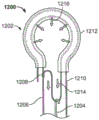
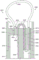
Fig. 12 and 13A-13C illustrate two variations of snare loop assemblies suitable for use with the closure devices described herein.
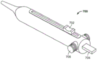
Fig. 14 shows a perspective view of an exemplary variant of the closure device described herein.
FIG. 15 shows a side cross-sectional view of a portion of one variation of the closure device described herein including a pulley suture.
Fig. 16A-16B illustrate a variation of the closure device described herein in which the snare is releasably connected to the elongate body.
Fig. 17A-17D illustrate different exemplary variations of snare configurations.
Fig. 18A and 18B show a perspective view and a side view, respectively, of a variant of a snare. Fig. 18C and 18D illustrate a method by which the snare of fig. 18A and 18B may be used to snare tissue.
Fig. 19A-19G illustrate several variations of knot screening mechanisms suitable for use with the closure devices described herein.
Fig. 20A-20C illustrate a retaining member that may be used with the devices described herein.
Fig. 21 shows an exemplary variant of an elongate body suitable for use with the devices described herein.
Fig. 22A and 22B show perspective and top views, respectively, of a variation of a separation conduit suitable for use with the devices described herein. Fig. 22C and 22D show perspective and top views, respectively, of another variation of a separation conduit suitable for use with the devices described herein.
FIG. 23A illustrates a front view of an exemplary variation of a tip portion suitable for use with the devices described herein. Fig. 23B and 23C show side cross-sectional views of the tip portion of fig. 23A.
Fig. 24A and 24B illustrate portions of two variations of tip portions suitable for use with the devices described herein.
Fig. 25A-25C illustrate perspective, front and side sectional views, respectively, of an exemplary variation of a tip portion suitable for use with the devices described herein. FIG. 25D shows a side cross-sectional view of a variation of the closure device including the tip portion shown in FIGS. 25A-25C.
Fig. 26A and 26B show an exemplary variant of a closure device comprising a separation conduit.
FIG. 27 shows an exemplary variation of a closure device including a separate conduit and suture tube.
28A and 28B illustrate a variation of a suture tube suitable for use with the devices described herein.
FIG. 29 shows a side cross-sectional view of a suture tube suitable for use with the devices described herein.
Fig. 30A-30D illustrate variations of the closure devices described herein that include a pulley suture.
Fig. 31A and 31B illustrate two variations of a tensioning device suitable for use with the closure devices described herein.
FIG. 32A shows a perspective view of a variation of a tensioning device suitable for use with the closure devices described herein. Fig. 32B and 32C show partial cross-sectional views of the tensioner shown in fig. 32A.
Fig. 33A-33G illustrate a variation of a tensioning device suitable for use with the closure devices described herein.
FIG. 34 illustrates a method of closing tissue using a closure device having a suture loop.
Fig. 35A-35D illustrate a variation of a closure device including a tensioning mechanism.
Detailed Description
Described herein are closure devices, handles and tensioning devices for actuating the closure devices, and methods for closing tissue using one or more closure devices. Generally, the closure device comprises a snare loop assembly, including snares and suture loops, such as those described in U.S. patent application No. 12/055213 entitled "device, system, and method for closing the left atrial appendage" filed 3/5 in 2008 and U.S. patent application No. 12/752873 entitled "tissue ligation device and controller therefor" filed 4/1 in 2010, the entire contents of both of which are incorporated herein by reference. The devices described herein may be suitable for use in minimally invasive access to the left atrial appendage (e.g., through a small incision above, below, or through the ribcage, through an incision in the costal cartilage or xiphoid process, through a port, through the vasculature, etc.).
Generally, the closure devices described herein include an elongate body and a snare loop assembly. In some variations, the closure device may further include a handle and/or a tensioning device. A handle or other control mechanism (e.g., a master-slave robotic system of a surgical procedure) may be used to control and actuate the snare loop assembly through the elongate body, as will be described in more detail below. The snare loop assembly, in turn, may be used to temporarily or permanently close, tighten, ligate, or otherwise restrain tissue. To accomplish this, the snare loop assembly may be changed between a delivery or "closed" configuration and a deployed or "open" configuration, or vice versa, as will be described in greater detail below. Placing the snare loop assembly in the closed configuration may allow the snare loop assembly to be advanced to a target location in a low-profile (low-profile) or may allow the snare loop assembly to be closed around a target tissue. Conversely, placing the snare loop assembly in the open configuration may allow the snare loop assembly to be placed around one or more target tissues, or may allow the snare loop assembly to release one or more target tissues previously enclosed by the snare loop assembly.
In use, the distal end of the elongate body may be advanced into the body towards a target tissue (e.g., the left atrial appendage). Such propulsion may be performed in a minimally invasive manner. During advancement, the snare loop assembly may be in a closed configuration to help prevent the snare loop assembly from hooking or snagging on tissue or other obstructions. Once the distal end of the elongate body has reached a position at or near the target tissue, the snare loop assembly may be opened to a deployed configuration. The snare loop assembly may then be advanced, moved, or otherwise manipulated to encircle at least a portion of the target tissue. The snare loop assembly may then be closed around the encircled tissue to close, ligate, or otherwise restrain the target tissue. The snare loop assembly can be reopened, repositioned and reclosed if desired. In some cases, a suture loop (not shown) or other restraining device may be tightened and released from the closure device to maintain the target tissue in a closed form. To remove the closure device from the body, the snare loop assembly may be reopened to release the target tissue (it being understood that the suture loop or other closure device may be held in place) so that the snare loop assembly and elongate body may be withdrawn. Once the target tissue is released, the snare loop assembly may be closed to facilitate withdrawal in a low profile. In variations where the closure device includes a tensioning device or mechanism, the tensioning device or mechanism may be used to release and/or tighten the suture loop from the snare loop assembly, as will be described in more detail below.
The closure device may include one or more additional features, as will be described in more detail below. In certain variations, the snare loop assembly comprises one or more force reducing suture locks. As will be described in greater detail below, these elements may be used to releasably or permanently connect various parts of the snare loop assembly while reducing the force transmitted to one or more portions of the snare loop assembly. In other variations, the closure device may include one or more features that help retain at least a portion of the suture loop inside the elongated body when the device is in the open and/or closed configuration. In some of these variations, the closure device may include a suture hook engaged with a portion of the snare loop assembly. In other variations, the elongated body may include one or more separation conduits. The separation conduit may also include a suture tube attached thereto for releasably retaining at least a portion of the suture loop. In other variations, the elongate body may comprise a pulley suture engaged with one or more portions of the snare loop assembly. Each of these features will be described in greater detail below, and it should be understood that the closure device described herein may include any combination of these features.
Fig. 14 shows an exemplary variant of a closure device (1400). A snare loop assembly (1402), an elongate body (1404), and a handle (1406) are shown. As described above, handle (1406) may be used to control and actuate snare loop assembly (1402) through elongate body (1404) in order to move snare loop assembly (1402) between a closed configuration (as shown in fig. 14) and a deployed configuration (not shown), and vice versa.
Ring set
As noted above, the snare loop assembly of the closure devices described herein may be used to temporarily close or restrict one or more target tissues. Generally, the snare loop assembly includes a snare, a suture loop, and a retention member at least temporarily connecting the snare and the suture loop. The snare loop assembly may also include one or more force reducing suture locks, as will be described in more detail below. Fig. 1 shows an exemplary variant of a snare loop assembly (100) comprising a snare (102), a suture loop (104), and a retention member (106). The snare loop assembly (100) may be at least partially disposed in an elongate body (108) having a tip (110). The snare loop assembly (100) is shown in an open configuration in fig. 1, and the portion of the snare loop assembly (100) extending from the elongate body (104) may define a continuous aperture therethrough. The aperture may be defined by one or more components (e.g., a snare) of the snare loop assembly (100) and may be adapted to encircle tissue, such as the left atrial appendage. Generally, the snare (102) may be used to open and close a snare loop assembly (100), as will be described in more detail below. In some cases, the retention member (106) may be configured to releasably couple the suture loop (104) and the snare (102), and may be configured to release the suture loop (104) from the snare loop assembly (100) upon application of sufficient force to the suture loop (104).
Ring sleeve
In a variation of the snare loop assembly comprising a snare, the snare may be at least partially movable to change the snare loop assembly between an open configuration and a closed configuration. Generally, a portion of the snare may be housed within the elongate body, and another portion of the snare may extend beyond the distal end of the elongate body so as to at least partially define the aperture of the snare loop assembly. In some variations, one end of the snare is fixed relative to one or more portions of the closure device, while the other end may be advanced or retracted through the elongate body. Movement of the free end of the snare may vary the amount of snare loop assembly disposed outside the elongate body, and thus the size of the aperture defined thereby. Specifically, advancement of the snare through the elongate body may increase the size of the snare loop assembly aperture, while retraction of the snare may decrease the size of the snare loop assembly aperture to close the snare loop assembly. The free end of the snare may be manipulated in any suitable manner. In some variations, the snare may be directly connected to one or more portions of the handle, as will be explained in more detail below. In other variations, a hypotube, rod, or other rigid structure may be connected to the free end of the snare. This structure, in turn, may be moved by a handle which may facilitate advancement or retraction of the snare through the elongate body.
In variations in which one end of the snare is fixed relative to the closure device, the snare may be fixed to any suitable portion of the device. For example, in some variations, one end of the snare may be fixedly held in, on, or near the tip of the elongate body. In other variations, the fixed end of the snare may be fixed in one or more lumens of the elongate body. In further variants, the fixed end of the snare may be at least temporarily connected to the handle of the device. Although one end of the snare may be temporarily fixed relative to the closure device, it should be understood that the fixed end may be configured to be releasable and/or movable. Configuring the fixed end of the snare to be releasable and/or movable may provide a number of useful functions. In some cases, temporary or permanent device failure may cause the moveable portion of the snare to stick or hang. In these cases, it may be desirable to release the secured ends in order to allow the closure device to release the entrapped tissue. In other cases, it may be desirable to move the free end to provide for adjustment of the snare by using both ends.
When one end of the snare is configured to be temporarily fixed relative to the elongate body, the end of the snare may be released from its fixed relationship in any suitable manner. For example, in some variations, the ends of the snare may be temporarily held in a fixed manner by a frangible member. Fig. 16A and 16B show a variation in which one end of the snare (1600) may be releasably secured to the elongate body (1602) by a frangible member (1604). In particular, fig. 16A and 16B show a portion of the elongated body (1602) having at least one lumen (1605). In this variation, a portion of the cavity (1605) may be subdivided into at least first and second subcavities (1606 and 1608, respectively). As shown in fig. 16A, first subchamber (1606) has a first portion (1610) with a first cross-sectional area and a second portion (1612) with a second cross-sectional area. The end of snare (1600) may be placed in first portion (1610) of first subcavity (1606) and may be connected to the distal end of frangible member (1604), as shown in fig. 16A. A frangible member (1604) may pass through the second portion (1612) of the first subcavity (1606) and through the cavity (1605).
The connection of the snare (1600) to the frangible member (1604) may help temporarily lock the end of the snare (1600) in place. The proximal end (not shown) of the frangible member (1604) may be temporarily connected to one or more portions of the device handle (not shown) in a fixed manner. Because the proximal end of the frangible member (1604) is held in place, the frangible member (1604) may prevent the snare from being pulled far out of the end of the elongate body (1602). Furthermore, the cross-sectional area of the first portion (1610) may be different from the cross-sectional area of the second portion (1612), such that the end of the snare (1600) cannot pass from the first portion (1610) into the second portion (1612). In this way, the snare (1600) is prevented from moving proximally into the elongate body (1602). Furthermore, in some variations, at least a portion of the snare (1600) and the first portion (1610) may have a non-circular cross-section (e.g., oval, triangular, square, polygonal, or irregular geometric shape) such that the snare (1600) housed within the first portion (1610) cannot rotate relative to the first portion (1610). Because the end of the snare (1600) is prevented from moving proximally, distally, or from rotating relative to the first portion (1610) of the first subcavity (1606), the end of the snare can be effectively fixed relative to the elongate body (1602).
The frangible member (1604) may be configured such that applying sufficient force to the frangible member (1604) is sufficient to break the connection between the frangible member (1604) and the snare (1600). To release the snare (1600) from its secured position, a user may pull directly or indirectly (e.g., via one or more handle components) on the proximal end of the frangible member (1604). Because the snare (1600) is prevented from moving proximally into the second portion (1612), sufficient proximal force applied to the frangible member (1604) can be used to break the engagement between the frangible member (1604) and the snare (1600), thereby releasing the snare (1600), as shown in fig. 16B.
Snares described herein can be made from any suitable material or combination of materials. For example, in some variations, the snare may be made of a shape memory material such as a shape memory alloy (e.g., nitinol, etc.), or may be made of stainless steel, polyester, nylon, polyethylene, polypropylene, combinations thereof, and the like. In variations where the snare is made of a shape memory material, the snare may be configured to assume a particular shape or configuration when the snare loop assembly is in the open configuration, but may also be at least partially retracted into the elongate body to place the snare loop assembly in the closed configuration. For example, as shown in fig. 1 above, the snare (102) may form a generally circular loop when the snare loop assembly (100) is in the open configuration. Although shown as being generally circular in fig. 1, the snare (102) may form a loop of any given shape. Fig. 17A-17D illustrate several additional snare configurations. In the variation shown in fig. 17A, snare (1700) may form a tear-drop shaped loop (1702) when in the deployed configuration. In the variation shown in fig. 17B, the snare (1704) may form an oval or elliptical loop (1706) when in the deployed configuration. In the variation shown in fig. 17C, the snare (1708) may form a substantially triangular loop (1709) when in the deployed configuration. Further, in certain variations, the snare loop may be angled with respect to the elongate body. For example, fig. 17D shows a side view of the closure device (1710) with the snare (1712) exiting the elongate body (1714), the snare (1712) being at an angle (θ) relative to the longitudinal axis (1716) of the elongate body. The angle (θ) may be any suitable angle. For example, the angle (θ) may be about 5 °, about 15 °, about 30 °, about 45 °, about 60 °, about 75 °, about 90 °, between about 40 ° and about 50 °, between about 35 ° and about 55 °, between about 30 ° and about 60 °, and the like. A snare (1712) angled relative to the elongate body (1714) may help the snare (1712) capture tissue because angling may better position the snare (1712) relative to tissue as the closure device is moved in the body.
Fig. 18A-18D show another variation of snare (1800). In this variation, the snare (1800) may form a hook-loop (1802) when the snare (1800) extends from the elongate body (1804) in the open configuration. Fig. 18A shows a perspective view of snare (1800), while fig. 18B shows a side view of snare (1800). Because the loop (1802) is bent back on itself to form a hook shape (as highlighted in the side view of fig. 18B), the snare (1800) may help form a space between body tissues when in the open configuration. For example, when opened in the pericardial space, as shown in fig. 18C, snare (1800) may lift the pericardial cavity (1806) away from the heart (1808). Creating additional space within the pericardial cavity may make the snare (1800) easier to capture tissue, such as the left atrial appendage (1810), as shown in fig. 18D.
Suture loop
The snare loop assembly described herein may also include a suture loop for holding tissue in a closed manner. Generally, the suture loop may be releasably connected to the snare, e.g. by a retaining member, as will be explained in more detail below. Furthermore, the suture loop may include a suture knot, but is not required. The suture knot may be any suitable knot including, but not limited to, a slip knot (e.g., a unidirectional slip knot). In some variations, at least a portion of the knot may be retained within the tip of the elongate body, as will be described in greater detail below. In other variations, the suture knot may be temporarily held in a fixed relationship with the elongated body, as will be described in more detail below.
In variations where the suture loop includes a sliding knot, the suture may be advanced or retracted through the sliding knot to change the size of the suture loop. In some cases where the suture knot remains within the elongated body or against the pointed end of the elongated body, the suture knot may not move while the size of the suture loop is changed. This may help prevent the closure device from damaging tissue, as will be described in more detail below.
In some variations, the suture loop further comprises a one-way locking structure. In these variations, the one-way locking structure may be any structure that can be advanced in one direction along the suture but resists movement in a second direction. In these variations, a locking structure may be advanced over a portion of the suture loop to help lock the suture knot in place. For example, in some variations, the one-way locking structure may include a bead or mechanical structure placed at least partially around the suture. In these variations, the bead may include one or more teeth or protrusions that allow the bead to advance in one direction along the seam, but prevent or resist movement in the opposite direction. The locking structure may be advanced by one of the closure devices described herein, or may be advanced by a separate device after the suture loop has been released from the closure device.
The suture loop may be made of any suitable material for use in draining or sealing. For example, it may be made of biodegradable materials (e.g., polylactic acid, polyglycolic acid, polylactic-glycolic acid copolymer, etc.), or may be made of non-biodegradable materials (e.g., metals, steel, polyesters, nylon, propylene, silk, combinations thereof, etc.).
When the suture loop is tightened to seal tissue, the tissue may be pulled into the suture knot of the suture loop. If too much tissue is drawn into the suture knot, the suture knot may become clogged or obstructed in a manner that prevents the suture loop from being further tightened. In some variations, the suture loop may include one or more pledgets (or tube segments) to help conceal a portion of the suture knot. FIGS. 19A-19G illustrate several variations of suture loops including knot shielding elements. In fig. 19A, both legs of the suture loop (1900) are passed through the pledget (1902). The swab for use with the device described herein may be made of any suitable material, such as, for example, polyurethane foam, felt, teflon fabric, dacron, collagen, and the like. Fig. 19B shows another variation of the suture loop (1904) in which the pledget (1905) is folded over and the two legs of the suture loop (1904) are threaded therethrough. By increasing the thickness of the pledget (1905) disposed between the suture knot (1906) and tissue (not shown), the pledget (1905) can further reduce the amount of tissue pulled into the suture knot (1905). Fig. 19C shows another variation of a suture loop (1908) including a pledget (1910) in which only a portion of the pledget (1910) is tucked. In this variation, one leg (1912) of the suture loop (1908) may pass through the folded back portion of the pledget (1910) while the other leg passes through the single layer portion of the pledget (1910).
Fig. 19D shows another variation of the suture loop (1914) in which one leg (1916) of the suture loop (1914) and the free end (1918) of the suture loop (1914) pass through the pledget (1920). Fig. 19E shows a variation of the suture loop (1922) in which both legs and the free end (1924) of the suture loop (1922) pass through the pledget (1926) all. It should be understood that in some of these variations, one or more portions of the swab (1926) may be sized or otherwise configured to fit within one or more portions, cavities, or grooves of the elongated body. Fig. 19F shows a variation of the suture loop (1928) wherein the suture knot (1930) is at least partially shielded by the tubing (1932). In this variation, the legs of the suture loop (1928) may pass through the end of the tube (1932) and the suture knot (1930) may exit through a hole (1934) in the side of the tube (1932). Fig. 19G shows another variation of the suture loop (1936) in which the suture knot (not shown) is shielded by tubing (1938). In this variation, the legs of the suture loop (1936) may exit from a groove (1940) in the side of the conduit (1938), while the free end of the suture loop (1936) may exit from an end of the conduit (1938).
Holding member
Fig. 20A-20C illustrate exemplary retaining members that may be used with the devices described herein. Fig. 20A shows an end view of the retaining member (2014) having first and second lumens (2016, 2018) for retaining the closure element and its suture loop therein. In this variation, the second lumen (2018) has a slit or other opening (2020) along its length for allowing passage of a suture when it is ready to be deployed. Of course, it should be understood that the first and second cavities may be positioned or oriented in any suitable manner relative to each other, and similarly, the slit or other opening on the second cavity may be positioned or oriented in any suitable manner relative to the first cavity (e.g., it may be about 180 °, about 150 °, about 120 °, about 90 °, about 60 °, about 30 °, etc. from the first cavity (2016)). Fig. 20B shows a retaining member having a first cavity (2022), a second cavity (2024), and a slit (2026). In this variant, the slit (2026) is located closer to the first cavity (2022) than the slit of fig. 20A. The width or gap of the slit opening may be selected as desired or appropriate. Similarly, the slit need not extend or be continuous along the entire length of the retaining member. In some variations, the slit may have pointed ends or arms along its length to help capture and retain the suture therein. In other variations, the slits may be covered with a biodegradable polymer at spaced locations therealong, temporarily serving to staple or secure the suture. Of course, in other variations, the retaining member does not include a slit, but rather some other type of retaining mechanism, such as a tip or spike as described immediately above. In other variations, there is no slit or opening in the retaining member and the suture loop is released upon removal or withdrawal of the retaining member and closure device.
Fig. 20C provides another variation of a retaining member. In this variant, the retaining member has a first cavity (2028), a second cavity (2030), and a separation zone (2032). The separation zone may be configured in any suitable manner. For example, the detachment zone may include a perforation zone adapted to perforate and release the suture upon application of force. Alternatively, the separation region may be thin-walled or other types of weakened regions that may be configured to break and release the suture. It should be understood that the retaining member may have any suitable geometry or shape and may be made of any suitable material. Similarly, the cavity need not be a full circle or a geometric shape having a circular cross-section. When these or other types of retaining members are used, the suture loop may be torn, pulled through the retaining member, or otherwise released from the retaining member after the retaining member has been properly positioned and tightened as desired.
Elongated body
As briefly mentioned above, the elongate body of the closure devices described herein may connect the distal end of the snare loop assembly and a handle or actuation mechanism, while still allowing control of the snare loop assembly by the elongate body. In particular, at least a portion of some of the snare loop assembly components may be housed within the elongate body, and may be connected to the handle by the elongate body. In some variations, at least a portion of the elongate body may be flexible, which may facilitate navigation of the elongate body in and through tissue.
Fig. 21 illustrates one exemplary variation of an elongated body suitable for use with the closure devices described herein. An elongate body (2100) is shown attached to a handle portion (2102). The elongate body (2100) may include a tip portion (2103), a curved portion (2104), a first lumen (2106), a second lumen (2108), and a third lumen (2110). Although shown in fig. 21 as having a single curved portion (2104), elongate body (2100) may have no curved portion or may have multiple curved portions in different portions of elongate body (2100). Further, in some variations, the closure device may include one or more mechanisms that function or have the effect of changing the shape of the elongate body (2100). In the case where the elongate body (2100) includes one or more curved portions (2104), the elongate body (2100) may be temporarily straightened using a tube, mandrel, or other straightening mechanism (not shown). For example, a rigid tube or mandrel may be placed in one or more lumens of the elongated body (2100), which may temporarily straighten any curved portions. Straightening may be performed during delivery (e.g., prior to reaching the pericardial space when used in conjunction with a left atrial appendage ligation procedure), and the straightening mechanism may be withdrawn at any point to allow the elongate body (2100) to return to its initial configuration. The straightening mechanism may be made of any suitable material (e.g., rigid plastic, stainless steel, combinations thereof, etc.).
In other variations, one or more pre-bent tubes or mandrels may be inserted into the elongate body (2100) to create one or more bent portions. In other variations, one or more pull wires may be disposed within, on, or around the elongate body (2100), and the elongate body (2100) may be flexed or bent when one or more of the pull wires is pulled, pushed, or otherwise manipulated. It should also be understood that any of the devices described herein may be configured to be steerable or may be configured to use robotics (e.g., configured for use with one or more robotic devices or other automated devices).
Chamber
The elongated bodies described herein may have any suitable number of lumens. It should be understood that when the term "lumen" is used herein, it may be used to describe any aperture or channel extending through the length of the elongated body or other portion of the closure device. It should be understood that the cavity need not be completely enclosed (i.e., the cavity may include one or more slots, slits, gaps, or other openings along a portion or the entire length of the cavity). The elongate body may comprise one, two, three, four or five or more lumens. A portion or all of the lumen may extend completely through the elongate body (i.e., from the proximal end of the elongate body to the distal end of the elongate body). Other lumens may pass through only a portion of the elongated body (e.g., from one end to an intermediate point along the elongated body, or between two intermediate points along the elongated body). For example, in the variation shown in fig. 21, the third lumen (2110) runs along the length of the elongated body (2100) from the proximal end of the elongated body (2100) to an intermediate point. In this variation, one or more guidewires, visualization devices, or working devices (not shown) may be passed through the third lumen (2110).
The various components of the snare loop assembly may be housed within any one or more lumens of the elongate body. For example, in some variations, all of the components of the snare loop assembly may be housed in a single lumen. In other variations, different portions of the snare loop assembly may be at least partially housed in different lumens. For example, in certain variations, the elongate body may comprise at least two lumens. In these variations, the free end of the suture loop may pass through the first lumen to the handle portion, while the free end of the snare may pass through the second lumen to the handle portion. In variations in which the suture loop accommodates excess suture in the elongate body, the excess suture may be accommodated in any suitable lumen, as will be described in more detail below. For example, in some variations, the excess suture may be held in the same lumen as the free end of the suture loop, in the same lumen as the free end of the snare, or in a completely different lumen.
In some cases, one or more lumens of the elongated body may be at least partially divided into one or more subcavities. In particular, a chamber may be split into two or more subcavities along a portion of the length of the chamber. In some of these variations, a separation conduit may be used to divide a chamber into two or more sub-chambers. Fig. 22A-22D illustrate several variations of separation conduits suitable for use with the closure devices described herein. In particular, fig. 22A and 22B show a perspective view and a top view, respectively, of a variant of the separation conduit (2200). In this variation, the separation conduit (2200) may include a first cavity (2202) and a second cavity (2204) extending therethrough. When placed inside one of the lumens of the elongated body (not shown), the first lumen (2202) and the second lumen (2204) of the separation conduit (2200) may serve as subcavities within the lumen of the elongated body. In this way, the separation conduit (2200) may allow the lumen to be a single channel along one length of elongate body and two or more separate channels along another length of elongate body.
It should be understood that although shown in fig. 22A and 22B as having two lumens ((2202) and (2204)), separation conduit (2200) may include any suitable number of lumens (e.g., one, two, three, four, or more). In this way, the cavity of the elongate body may be subdivided into any suitable number of sub-cavities along the length of the separation conduit. It should be noted that in certain variants, the separation conduit may have only a single lumen therethrough. In these variations, the separation conduit may not divide a chamber into a plurality of sub-chambers, but may vary the size and shape of the chamber along a portion thereof. It should also be understood that the lumen of a portion or all of the separation conduit (2200) may pass through only a portion of the separation conduit.
In other variations, a separation conduit may include one or more grooves or channels. The slots or channels, when placed inside the cavity of the elongated body, may form fully enclosed subchambers. For example, fig. 22C and 22D show one such variation of the separation conduit (2206). Specifically, fig. 22C shows a perspective view of the separation conduit (2206) including a lumen (2208) and a channel (2210) along an outer surface of the separation conduit (2206). When the separation conduit (2206) is placed inside the lumen (2211) of the elongated body (2212), as shown in the top view in fig. 22D, the channels (2210) may form a closed lumen, which may be defined in part by the separation conduit (2206) and in part by the lumen wall. It should be understood that the separation conduits described herein may include any suitable number and combination of channels and/or cavities.
In certain variations, it may be desirable to configure the separation conduit to allow one or more components of the snare loop assembly to be released therethrough. For example, in some instances, a portion of the suture loop may pass through two or more lumens/channels separating portions of the tubing, as will be described in more detail below. To release the suture loop from the device, it may be necessary to remove any excess suture from the separation tube without damaging or breaking the suture loop. Thus, in some variations, the separation conduit may include one or more separation zones (not shown) between two or more lumens, channels, or combinations thereof. The separation zone may be constructed in any suitable manner, such as those described above with respect to the retaining member. For example, in some variations, the separation region may include a perforation region adapted for perforation and allowing the suture to be pulled therethrough as the suture loop is cinched. Alternatively, in some variations, the separation region may be thin-walled or other types of weakened regions that may be configured to tear or otherwise break upon application of force from a suture or other device component.
Tip end
The elongated body typically includes a tip portion at its distal end. In some variations, the tip of the elongate body may be formed separately from the elongate body and may be connected to the elongate body during assembly of the device. In other variations, the tip portion may be integrally formed with the elongated body as an integral device. The tip portion may provide a number of useful functions for the closure device. In some cases, the tip may be configured to be atraumatic, which may serve to reduce the risk of damaging tissue as the proximal end of the elongate body is moved within the body. In other cases, the tip may allow certain portions of the snare to pass through the elongate body while keeping other portions in place relative to the elongate body, as will be described in more detail below.
The tip portion may, but need not, have the same number of lumens as the elongated body. Indeed, in some variations, the tip portion may divide one or more lumens of the elongated body into two or more subcavities. In some of these variations, the tip portion may receive at least a portion of a separation conduit. In other variations, the tip portion may vary the size or shape of one or more lumens of the elongated body.
Fig. 23A-23C illustrate the distal end of an exemplary variation of a closure device (2300). Specifically, fig. 23A shows a front view of the tip (2302) of the elongated body (2304). As can be seen herein, tip (2302) may include a first sub-cavity (2305), a second sub-cavity (2306), and a third sub-cavity (2308). Fig. 23B shows a side cross-sectional view of elongated body (2304) and tip (2302). As shown, first subchamber (2305) and second subchamber (2306) may exit into first chamber (2310) of the elongate body, while the third subchamber may exit into second chamber (2312).
In some variations, one subcavity may be configured to at least partially receive a suture knot of a suture loop. For example, the second subcavity (2306) shown in fig. 23B may include a junction receiving groove (2316) having a first cross-sectional area and a second portion (2318) having a second cross-sectional area. Suture knot (2320) of suture loop (2330) may be placed in knot-receiving groove (2316) of second subcavity (2306), as shown in fig. 23C. The free end of the suture loop (2330) may pass through the second portion (2318) into the first lumen (2310) of the elongated body (2304). Further, the cross-sectional area of knot receiving groove portion (2316) may be different (e.g., smaller and/or have a different shape) than the cross-sectional area of second portion (2318), such that suture knot (2320) cannot pass from knot receiving groove portion (2316) into second portion (2318). In this way, suture knot (2320) may be prevented from moving proximally into elongate body (2304). Furthermore, because the suture knot (2320) may be at least partially received in the knot receiving groove (2316) of the second subcavity (2306), pulling of the suture knot into the third subcavity (2308) may be prevented when excess suture is pulled into the elongated body (2304), as will be described in greater detail below.
Fig. 23C also shows how other components of the snare loop assembly (2324) may be positioned relative to the tip (2302). As shown, the snare loop assembly (2324) may include a snare (2326), a suture loop (2330), and a retention member (2328). The retention member (2328) releasably connects a portion of the snare (2326) and the suture loop (2330). The free end of the suture loop (2330) may pass through the second subcavity (2306) and the first chamber (2310) to the handle portion (not shown), while an amount of excess suture (2330) may be contained within the pointed third subcavity (2308) and the elongated second chamber (2312). At least a portion of the excess suture (2330) may be retained within the elongate body by one or more suture management features (not shown) described below. Further, one end of the snare may be temporarily or permanently secured at least partially within the first subcavity (2305), while a free end of the snare (2326) may be moved at least partially through the third subcavity (2308) of the tip and the second lumen (2312) of the elongate body to open and close the snare loop assembly (2324).
In variations where the pointed end of the elongated body includes a knot receiving groove, it may be desirable to eject or remove the suture knot from the groove during or prior to cinching the suture loop. Removing the suture knot from the groove may improve the ability of the suture loop to tighten around the tissue by improving the displacement of the knot relative to the tissue. The suture knot may be removed from the groove in any suitable manner. For example, fig. 24A and 24B illustrate two suitable variations in which a suture knot may be advanced from a knot-receiving groove. In a first variation, the closure device (2400) can include a balloon (2402) or other expandable structure disposed in a knot receiving recess (2406), as shown in fig. 24A. When the balloon is compressed, the suture knots (2408) of the suture loops (2410) may be at least partially received in the knot receiving grooves (2406). When the balloon is inflated, it can move at least a portion of the suture knot (2408) out of the knot-receiving groove (2406). In another variation, the closure device (2412) may include a pusher (2414) disposed at least partially in the knot receiving recess (2416), as shown in fig. 24B. In this variation, the pusher (2414) may be advanced within the knot-receiving groove (2416) to push out at least a portion of the suture knot (2418), and in some cases the entire suture knot (2418), from the knot-receiving groove (2416).
In other variations of the closure devices described herein, the tip portion may include a distal recess. Fig. 25A-25D illustrate one such variation of the tip (2500). Fig. 25A-25C show perspective, front, and side cross-sectional views of the tip (2500). Proximal recess (2502) for receiving the distal end of the elongated body (not shown), distal recess (2504), first subcavity (2506), second subcavity (2508), and third subcavity (2510) are shown. While shown in fig. 25A-25C as being formed separately from the elongated body, it is to be understood that the tip may be integrally formed with the elongated body.
Fig. 25D shows a side cross-sectional view of one example of how the tip (2500) may be incorporated into a closure device (2512). A tip (2500) is shown attached to an elongated body (2514). As shown, elongate body (2514) may include a first lumen (2516) and a second lumen (2518) and may be disposed within proximal recess (2502) of tip (2500). A first subcavity (2506) and a second subcavity (2508) may be introduced into first chamber (2516), while a third subcavity may be introduced into second chamber (2518).
The closure device (2512) may further comprise a separation conduit (2520) which may be partially disposed in the third subcavity (2510) of the tip (2500) and the second chamber (2518) of the elongate body (2514) and which may divide the chamber into subcavities (2522) and (2524). Fig. 25D also shows a snare loop assembly (2526) including a snare (2528), a suture loop (2530), and a retention member (2532). One end (2534) of the snare (2528) may be fixedly connected to the tip (2500) via the first subcavity (2506) or may be connected in the cavity (2516) through the subcavity (2506), while the free end of the snare may be advanced or withdrawn through the subcavity (2524) of the separation conduit (2520). Similarly, the free end (2536) of the suture loop (2530) may pass through the second subcavity (2508) of the tip (2500), while a portion of the excess suture of the suture loop (2530) may be received in the subcavities (2522) and (2524) of the separation conduit (2520).
Suture knot (2538) may be received in distal recess (2504). Further, the second subcavity (2508) of the tip (2500) and the subcavity (2522) of the separation conduit (2520) may be sized such that the suture knot (2538) cannot enter into each subcavity, thus preventing the suture knot (2538) from being pulled or pushed into the elongated body (2514). Further, by placing the ends of the suture knot against the entrances of the subcavities, the suture loop (2530) can be tightened around the tissue while minimizing the amount of tissue that can be pulled into the suture knot (2538) when tightening the suture loop (2530).
Excess suture management
In the operation of the closure device, it may be desirable to be able to open and close the snare loop assembly without prematurely releasing the suture loop from the snare assembly. Because the size of the continuous aperture defined by the snare loop assembly changes as the snare loop assembly is opened and closed, it may be necessary to change the size of the suture loop to accommodate this change in aperture size and prevent the suture from being prematurely released from the snare loop assembly. In some variations, opening the snare loop assembly may pull the suture through the slip knot to increase the size of the suture loop. However, this may provide sufficient force to the suture loop to break or separate the suture. To help prevent such undesirable results, the suture loop may be sized such that the size of the suture loop is as large or larger than the size of the aperture defined by the snare loop assembly when the snare loop assembly is in the open configuration. Thus, when the snare loop assembly is opened into the deployed configuration, the suture loops may be of similar size without the need to advance additional suture through the suture knot. However, pre-forming the suture loop to such a size may result in additional slack in the suture loop when the snare loop assembly is in a closed configuration. To help prevent excess suture from tangling or catching on anatomical structures, instruments, or other obstructions, a portion or all of the suture loop may be loosely retained inside the elongate body when the snare loop assembly is opened and/or closed.
Accordingly, the closure devices described herein may include one or more excess suture management features that may be used in any suitable manner. In some cases, the feature may be configured to apply a force to the excess suture when the device is in the open and/or closed configuration. The force may act to pull excess suture into the elongated body or may temporarily prevent excess suture from exiting the elongated body. In addition, the force may act to prevent excessive suture knotting or bunching, which may potentially affect the performance of the device. The following is a discussion of many different potential suture management features suitable for use with the closure devices described herein. It should be understood that the closure devices described herein may include any combination of these suture management features.
Sewing hook
In some variations, suture hooks may be used to hold excess suture within an elongated body. Fig. 2 shows one such variation of a snare loop assembly (200) with a suture hook (202). A snare (204), a suture loop (206) with a suture knot (208), and a retention member (210) are also shown. As shown in fig. 2, the suture hook (202) may retain excess suture from the suture loop (206) within the elongated body (not shown). In variations where the elongated body has multiple lumens, the suture hook (202) may hold excess suture in any suitable lumen.
In some variations, the proximal end of the suture hook may be movable relative to the elongate body as the snare is advanced from or withdrawn through or within the elongate body. Fig. 10 shows a side cross-sectional view of a portion of a closure device (1000) including an elongated body (1002) having a lumen (1004) disposed therethrough and connected to an interconnect (1006) of a handle (not shown). It should be understood that while fig. 10 illustrates having only one lumen (1004) disposed through the elongated body, the elongated body (1002) may have any number and configuration of lumens, as described above. Also shown in fig. 10 is a portion of snare (1008) connected to hypotube (1009) and suture hook (1010) engaged with a portion of suture loop (1012). As described above, snare (1008) may be advanced or withdrawn through elongate body (1002) or within elongate body (1002) to open or close snare loop assembly (not shown).
When the snare (1008) is advanced and the snare loop assembly is open, the suture loop (1012) may pull the suture hook (1010) toward the distal end of the elongate body (1002) to release a portion of excess suture from the elongate body (1002) or allow a portion of excess suture to advance within the elongate body (1002). In some variations, the suture hook (1010) includes a spring (1014). The spring (1014) may expand as the suture hook (1010) moves toward the distal end of the elongated body (1002). Conversely, closing the snare loop assembly may reduce the force applied to the suture hook (1010) by the suture loop (1012), which may allow the restoring force of the spring (1014) to pull the suture hook (1010) proximally. This in turn may pull any excess suture back into or through a portion of the elongated body (1002). The suture loop (1012) may remain of the same size as the snare loop assembly because excess suture is released from the elongate body (1002) when the snare loop assembly is open and the excess suture is withdrawn into the elongate body (1002) when the snare loop assembly is closed. Furthermore, because excess suture is tucked into the elongate body when held by the suture hook (1010), the suture hook (1010) need only be configured to move half of the snare (1008) to keep the suture loop (1012) the same size as the snare loop assembly.
It should be understood that although shown in fig. 10 as having one end connected to the suture hook (1010) and the other end connected to the interconnect (1006), which will be described in more detail below, the spring (1014) may be connected to any suitable portion or portions of the closure device (1000). In some variations, the spring may be connected to one or more elements of the handle, as will be described in more detail below. In other variations, the spring may be connected to one or more portions of the elongated body (1002). In other variations, the suture hook (1010) does not include a spring at all. In some of these variations, at least a portion of the suture hook (1010) can be stretched or otherwise deformed to allow excess suture to be pulled from the elongated body (1002). For example, the suture hook (1010) may comprise an elastic material or a combination of materials that are capable of being stretched and returned to an unstretched state. In such cases, the one or more elastic materials may stretch when the snare loop assembly is open to allow excess suture to be pulled from the elongate body (1002) or through a portion of the elongate body (1002). When the snare loop assembly is closed, the suture hook (1010) may return to its unstretched state, and thus may pull excess suture back into the elongate body (1002) or through a portion of the elongate body (1002).
In variations where excess suture of the suture loops (1012) is held in the elongate body by the suture hooks (1010), an additional step may be required to release the suture loops (1012) from the snare loop assembly. Once the snare loop assembly is advanced over the target tissue and closed on the tissue, excess suture that may be present in the suture loop (1012) is retained in the elongate body by the suture hook (1010). This slack may first have to be removed before the suture loop (1012) may be released from the snare loop assembly. To accomplish this, excess suture may be pulled through a suture knot (not shown) to reduce the size of the suture loop (1012). In some variations, the suture hook (1010) may be configured to deform upon application of a sufficient force thereto. Further, in some variations, the suture hook (1010) includes a stop (1016) that prevents the suture hook (1010) from moving distally beyond a certain point. Thus, as the suture is drawn through the suture knot and the size of the suture loop (1012) decreases, the suture loop (1012) places an increased force on the suture hook (1010). The suture hook (1010) may be moved toward the distal end of the elongated body (1002) until the stop (1016) engages the interconnect (1006). It should be noted that stop (1016) may engage with any suitable structure in closure device (1000). When the stop (1016) engages with the interconnect (1006), the suture hook (1010) is held in place, and eventually the force exerted by the suture loop (1012) may deform the end of the suture hook (1010) and release the remaining excess suture.
After the suture loop (1012) has been released from the suture hook (1010) and excess suture removed from the suture loop (1012), any additional suture pulled through the suture knot may begin to release the suture loop (1012) from the snare loop assembly. Any excess suture may remain within the elongate body (1002) if the snare loop assembly is closed around tissue prior to release of the suture loop (1012). Thus, any excess suture removed from the suture loop (1012) is contained within the elongated body (1002). Because the suture is contained within the elongated body (1002), it does not rub against or contact tissue disposed outside of the elongated body (1002). Further, as the suture loop (1012) is released from the snare loop assembly, the suture is released directly into contact with the tissue. Thus, a user may remove excess suture from the suture loop (1012) and release the suture loop (1012) from the snare loop assembly without rubbing or sliding against the tissue. Because tissue may be damaged when the suture is slid or rubbed against the tissue, the devices described herein may help to reduce damage to the tissue as much as possible in this manner. Once the suture loop (1012) is fully separated from the snare loop assembly, it may be tightened to ligate the target tissue.
As shown in fig. 10, snare (1008) and suture hook (1010) may be, but need not be, disposed in the same lumen (1004) of elongate body (1002). In variations where the snare (1008) is disposed in the same lumen (1004) as the suture hook (1010), there may be a risk of the snare (1008) becoming entangled with the suture hook (1010). Furthermore, because the suture hook (1010) only needs to move half of the snare (1008) when opening or closing the snare loop assembly, the snare (1008) may rub against the spring (1014), which in turn may cause the spring (1014) to rub against the inner wall of the lumen (1004). Such friction may interfere with actuation of the closure device (1000) and thus increase the force that a user must provide to actuate the device.
In some variations, the closure device may be configured to help prevent the suture hook from tangling with the snare. Fig. 11 shows one such variant of the middle of the closure device (1100). An elongate body (1102), hypotube (1106), snare (1108), spring (1110), suture hook (1112), sleeve (1114), and suture loop (1116) are shown, where the elongate body is connected to interconnect (1104). The free end of snare (1108) may be connected to hypotube (1106), as described above. Further, the suture hook (1112) may be connected to the hypotube (1106) via a spring (1110). Further, the spring (1110) may be disposed around the snare (1108), which may help prevent the spring (1110) from tangling with the snare (1108). Further, this may reduce the amount of space occupied by the snare (1108) and the spring (1110), which in turn may allow the snare and spring to be placed within a smaller lumen without increasing the amount of friction that occurs between the spring and the inner wall of the lumen.
The sleeve (1114) may also function to help prevent entanglement between the suture hook (1112) and the snare (1108). The cannula (1114) may have two or more lumens. The suture hook (1112) may pass through one lumen and the snare (1108) may pass through the other lumen. In some variations, a cannula (1114) may be connected to the snare (1108). The sleeves (1114) may be joined in any suitable manner (e.g., adhesive, welding, mechanical connection, etc.). In these variations, the sleeve (1114) may act as a stop to assist in releasing the suture loop (1116) from the suture hook (1112). With excess suture removed from the suture loop (1116), the spring (1110) may expand until it contacts the sleeve (1114) as described above. Upon contact with the cannula, the spring (1110) may be held in place, and the force exerted on the suture hook (1112) by the suture loop (1116) may cause the suture hook (1112) to deform and thus may release the suture loop (1116) from the suture hook (1112).
Separation pipeline
In some cases, it may be desirable to retain excess suture within the elongated body without the need for suture hooks. In some cases, one or more portions of the elongate body may bend or flex as a portion of the elongate body is advanced into or through the body to allow the snare loop assembly to reach a target location. However, bending or flexing of the elongated body may interfere with the movement of the suture hook or spring, which may potentially interfere with the ability of the suture hook to retain excess suture loops within the elongated body. Accordingly, it may be desirable to have a suture retention feature located in the distal portion of the elongated body.
Thus, in some variations of the closure devices described herein, one or more detachment conduits may be used to help retain excess suture within the elongate body, and thus may limit the exposure or release of excess suture from the elongate body. Fig. 26A and 26B show a side sectional view of one such variant of a closure device (2600). A lumen (2602) is shown in which the separation conduit (2604) is disposed. The separation conduit (2604) may divide the chamber (2602) into a first subcavity (2606) and a second subcavity (2608). The closure device (2600) may include a snare loop assembly (2610), which may include a snare (2612), a suture loop (2614), and a retention member (2616). As shown in fig. 26A and 26B, suture from the suture loop (2614) may pass through the first subcavity (2606) into the lumen (2602), where it may be connected to the snare (2612) via the retaining member (2616). Snare (2612) may be advanced or retracted through second subcavity (2608) to open and close the snare loop assembly, respectively. When the snare loop assembly (2610) is in the closed configuration, as shown in fig. 26A, excess suture of the suture loop (2614) may be retained in the snare lumen (2602) and the first subcavity (2606). When the snare is advanced to open the snare loop assembly, a portion of the suture held within the snare lumen may be advanced into the second subcavity (2608) to allow the snare loop assembly to open, as shown in fig. 26B. However, the presence of the detachment conduit may prevent excess suture from being pulled or pushed out of the tip of the closure device.
When a separation conduit is employed to retain excess sutures within the elongate body, it may be desirable for the separation conduit to include one or more separation regions to release excess sutures from the elongate body. As will be explained in greater detail below, these separation zones may allow a suture to pass therethrough during release of the suture loop. In particular, when excess suture is removed from the suture loop (i.e., when the suture is pulled through the suture knot to tighten the suture loop), the suture may be pulled through the separation zone, thereby allowing excess suture to span the space between the subcavities of the separation conduit.
It should be understood that any suitable detachment conduit segment, as described in more detail above, may be used to retain excess suture within the elongate body. It should also be understood that the separation conduit may be used in conjunction with a suture hook as described above or one or more additional excess suture management features. For example, in some cases, a separation conduit may be used in conjunction with one or more suture tubes. Generally, the suture tube has a first end that may be connected to the separation conduit and a second end that may be connected to a portion of the snare loop assembly and may temporarily retain excess suture therein. The suture tube may be made of any suitable material (e.g., polyether block amide (pebax), aromatic polyether based polyurethane (tecothane), nylon, etc.) and may include one or more separation zones that may allow excess suture to be removed from the suture tube.
Fig. 27 shows a partially cut-away view of one such variation of a closure device (2702) comprising an elongate body (2701), a separation conduit (2704) and a suture tube (2705). A separation conduit (2704) is shown that divides the chamber (2700) into a first sub-chamber (2706) and a second sub-chamber (2708). Also shown is a snare loop assembly comprising a snare (2712), a suture loop (2714), and a retention member (2716) at least temporarily connecting the snare (2712) and the suture loop (2714). As shown in fig. 27, the suture tube (2705) may releasably receive a portion of the suture loop (2714). One end of the suture tube (2705) may be connected to the separation conduit (2704) and the other end may be connected to a portion of the snare loop assembly (e.g., to the snare (2712) or the retention member (2716)). Due to this connection, one end of the suture tube (2705) may be fixed relative to the closure device (2702) while the other end may move with the snare (2712) and the closure element (2716) as the snare loop assembly moves between the closed and open configurations.
When placed in lumen (2700), suture tube (2705) can be folded over on itself at curved portion (2718). In this way, the portion of the suture loop (2714) that is temporarily received in the suture tube (2705) may be retained in the folded suture tube (2705), which may help prevent bunching of excess suture retained within the lumen (2700). The position of the curved portion (2718) may be moved as the snare loop assembly is changed between the open configuration and the closed configuration. Further, in some cases, the suture tube (2705) may have a tendency to return to an unbent shape, which may also cause the suture tube (2705) to have a tendency to twist and kink at points outside of the curved portion (2718). Thus, the suture tube may include one or more features that may help reduce twisting or kinking. For example, in some variations, the suture tube includes a plurality of cuts or slits that may function as a buffer. Fig. 28A and 28B illustrate one such variation of the suture tube (2800). FIG. 28A shows a suture tube (2800) that includes several V-shaped cuts (2802) along one side thereof. Each V-groove notch (2802) reduces the stiffness of the suture tube (2800) along the side and may make the suture tube (2800) more likely to bend or flex at the notch (2802). Thus, when the suture tube (2800) as shown in fig. 28B is placed within the cavity (2804) and folded over at the curved portion (2806), some of the V-shaped cuts (2802) may be substantially closed. Accordingly, the V-shaped notch (2802) may reduce the straightening force of the suture tube (2800), and thus may change the tendency of the suture tube (2800) to kink or twist. Although shown as V-shaped in fig. 28A and 28B, the cutouts may be any suitable shape (e.g., semi-circular, semi-elliptical, etc.).
In other variations, the suture tube may include one or more stiffening members that may affect the stiffness of one or more portions of the suture tube. Fig. 29 shows a cross-sectional view of one such variation of suture tube (2900). A suture tube (2900) is shown, including a suture lumen (2902), two reinforcement members (2904), and a detachment zone (2906). The stiffening member (2904) provides additional rigidity to a portion of the suture tube (2900). Thus, when suture tube (2900) is folded up and placed in the snare cavity, the side of suture tube (2900) containing reinforcement member (2904) will have greater resistance to bending, which may allow suture tube (2900) to better resist twisting and kinking. Further, the stiffening member (2904) may increase the column strength of the suture tube (2900), so the suture tube may more easily move as the snare advances or retreats. The reinforcing member may be any suitable structure such as, for example, a wire made of nitinol, steel, polymer, or the like. Although shown in fig. 29 as having two stiffening members (2904), it should be understood that the suture tube may include any suitable number of stiffening members (e.g., one, two, three, or more).
Pulley suture
In other variations, the snare loop assembly may include a second suture, i.e., a pulley suture, which may be engaged with a portion of the suture loop to help retain excess suture. Generally, one end of the pulley suture may be fixedly connected to a portion of the closure device (e.g., a handle or elongate body), while the other end may be temporarily or permanently connected to the snare loop assembly. In some variations, the body of the pulley suture may be looped around or tucked over a portion of the suture loop to help retain a portion of the suture loop in the elongated body. Fig. 30A-30D illustrate a variation of the closure device (3000), the closure device (3000) including a pulley suture (3002) that may be used to retain a portion of the suture loop (3010) within the lumen (3004) of the elongated body (3006). Shown in fig. 30A is a snare loop assembly (3008) comprising a suture loop (3010), a snare (3012), a retention member (3014), a first suture lock (3016), a second suture lock (3018), a first separation conduit (3020), and a second separation conduit (3022). Although shown in fig. 30A as having a first discrete tubing segment (3020) and a second discrete tubing segment (3022), the closure apparatus (3000) may include any number of discrete tubing segments (e.g., zero, one, two, three, or more). Furthermore, for clarity, the first and second split duct segments (3020, 3022) are not shown in fig. 30B and 30C.
As described above, one end (not shown) of the pulley suture (3002) may be fixedly connected to a portion of the handle (e.g., a suture pocket, as will be described in more detail below), while the other end may be temporarily connected to the snare (3012) via a second suture lock (3018) (which will be described in more detail below). The pulley suture (3002) may also be tucked over the portion of the suture loop (3010) between the knot (3024) and the second suture lock (3018), as shown in fig. 30A-30C. Such engagement may allow excess suture to be advanced through the elongate body (3006) when the snare (3008) is advanced (as shown in fig. 30B), and to be pulled distally into the elongate body when the snare (3008) is retracted (as shown in fig. 30C). Because both the suture loop (3010) and the pulley suture (3002) are temporarily connected to the snare (3008) (via the first suture lock (3016) and the second suture lock (3018), respectively), each suture can move the same distance when the snare (3008) moves. This movement may also advance or retract the point of overlap between the two sutures as the snare advances or retracts, respectively.
To release the suture loop (3010) from the closure device (3000), it may be necessary to terminate the engagement between the pulley suture (3002) and the suture loop (3010). This engagement may be terminated in any manner. In some variations, the pulley suture may be released from the suture lock and removed from the elongated body by pulling on an end of the pulley suture (3002). In fact, the pulley suture (3002) may be configured to pull out of or separate from the second suture lock (3018) upon application of a certain force to the pulley suture. As shown in fig. 30A-30C, the pulley suture (3002) may be tucked as it enters the second suture lock (3018). This may help release the pulley suture (3002) from the second suture lock (3018) because the change in direction may increase the shear force applied by the pulley suture (3002) to the second suture lock (3018). Further, the first suture lock (3016) may be configured such that the suture loop (3010) is released when a certain force is applied to the suture loop. To help prevent the suture loop (3010) from releasing prematurely from the retaining member (3014), the closure device (3000) may be configured such that the release force for the second suture lock (3018) is less than the release force for the first suture lock, but is not required.
To release the pulley suture (3002) from the snare (3008), one end of the pulley suture (3002) may be connected to one or more portions of the handle of the closure device. For example, fig. 30D shows a variation of a portion of the handle (3024) of the closure device (3000). As shown, one end of the pulley suture (3002) and one end of the suture loop (3010) may be connected to a suture pocket (3026). Although shown in fig. 30D as being attached to the same suture pocket, it should be understood that the pulley suture (3002) and suture loop (3010) need not be attached to the same handle component. In variations where the pulley suture (3002) and suture loop (3010) are connected to the same handle component (e.g., the variation shown in fig. 30D), the suture loop (3010) may include slack/excess suture inside the handle (3024). Thus, when the suture pocket (3026) is pulled away from the handle (3024), the pulley suture (3002) may be placed under tension before the suture loop (3010) is placed under tension. As such, as the suture pocket (3026) is pulled, the closure device (3000) may be configured to release the pulley suture (3002) from the second suture lock (3018) prior to tightening and releasing the suture loop (3010).
Fig. 15 shows another variation of a closure device (1502) including a pulley suture (1504). In this variation, the pulley suture (1504) may be releasably connected to the suture loop (1506) via a deformable connector (1508). One end of the pulley suture (1504) may be connected to the snare (1510) via a first suture lock (1512), while the other end of the pulley suture (1504) may be fixedly connected to any suitable portion of the closure device (e.g., the handle or one or more portions of the elongate body). As in the other variations described above, the pulley suture (1504) may be advanced or retracted with the snare (1510) to help retain a portion of the suture loop (1506) inside the elongate body (1514).
To release the engagement between the pulley suture (1504) and the suture loop (1506), the suture loop (1506) may be pulled away from the pulley suture (1504). This may be accomplished in any suitable manner, such as tightening the suture loop (1506) or pulling one end of the pulley suture (1504) relative to the suture loop (1506). When the suture loop (1506) and sliding suture (1504) are pulled away from each other, the two sutures may exert one or more forces on the deformable connectors (1508). These forces may cause the deformable connectors to deform, which may release the engagement between the suture loop (1506) and the pulley suture (1504).
Force reduction
In some cases, the suture hook or other suture retention feature may exert one or more forces on the suture loop as it pulls and retains excess suture in the elongated body. This force applied to the suture loop may in some cases cause the suture loop to separate from the snare loop assembly prematurely. This is shown in fig. 12. The distal end of a closure device (1200) is shown, which includes a snare loop assembly (1202) and a suture hook (1204). The snare loop assembly includes a suture loop (1206) having a suture knot (1208) releasably connected to the snare (1210) via a retention member (1212). When the suture loop (1206) is pulled into the elongated body (not shown) by the suture hook (1204), the suture hook (1204) may place one or more pulling forces on the suture of the suture loop (1206). These pulling forces may be converted to inwardly directed forces (1216) on the portion of the suture loop (1206) disposed within the snare loop assembly (1202). These inwardly directed forces (1216) may cause the suture loop (1206) to separate the suture loop (1206) from the retaining member (1212), thereby prematurely releasing the suture loop (1206) from the snare loop assembly (1202).
To prevent this problem, the snare loop assembly may include one or more suture locks. Fig. 13A-13C show one such variation of a closure device (1300). Fig. 13A shows a side cross-sectional view of a closure device (1300) comprising a snare loop assembly (1302), a suture hook (1304), and a suture lock (1306). The snare loop assembly (1302) may include a suture loop (1308) having a suture knot (1310) and coupled to the snare (1312) via a retention member (1314). Fig. 13B shows a front view of suture lock (1306). A suture lock (1306) is shown that includes a first cavity (1316), a second cavity (1318), and a slit (1320). Generally, at least a portion of snare (1312) may pass through first lumen (1316) and at least a portion of suture loop (1308) may pass through second lumen (1318). In certain variations, the force reducing element (1306) may be connected to the snare (1312) via the first lumen (1316).
Generally, the second lumen (1318) of the force reducing element (1306) may be configured to compress at least a portion of the suture loop (1308). Because sutures typically include a braided material disposed around a strength member, portions of the suture may be compressed without significantly affecting its strength. The second lumen (1318) may have a cross-sectional area that is smaller than a cross-sectional area of the suture. Thus, a portion of the suture loop (1308) may be advanced through or placed within the second lumen (1318), and the narrow cross-sectional area of the second lumen (1318) may act to compress the portion of the suture loop (1308) disposed within the second lumen, as shown in FIG. 13C. The compressed portion of the suture loop (1308) may cause the suture loop (1308) to resist being pulled or pushed through the force reducing element (1306). More specifically, the uncompressed portion of the suture loop (1308) may bear against the outer surface of the force reducing element, which may resist movement of the suture through the second lumen (1318).
Compressing a portion of the suture loop (1308) may help prevent the suture loop (1308) from prematurely releasing from the snare loop assembly (1302). As described above with reference to FIG. 12, the pulling force exerted on the suture loop may be translated into one or more forces that may separate the suture loop from the snare loop assembly. The force reducing suture lock (1306) may help reduce or eliminate the force exerted on the portion of the suture loop held by the snare loop assembly (1302). More specifically, compressing the portion of the suture loop (1308) disposed within the second lumen (1318) may prevent or reduce the transmission of a pulling force through the force reducing element. As described above, compressing the suture loop (1308) may cause the suture loop (1308) to resist movement through the force reducing element (1306). Thus, when the suture hook (1304) applies a pulling force to the suture loop (1308) as described above, the pulling force may attempt to pull the suture through the force reducing suture lock (1306), but any such movement is resisted by the compression caused by the force reducing element (1306). As a result, some or all of the pulling force is actually being attempted to pull the suture through the force reducing suture lock dissipation. This in turn may reduce or completely remove any force experienced by the suture on the other side of the force reducing element. Thus, the force reducing suture lock (1306) may reduce or remove forces that may cause the suture loop (1308) to prematurely release from the snare loop assembly (1302).
The force reducing suture lock (1306) may include one or more slits (1320) or other openings. These slits may allow the suture loop (1308) to pass through the slits when it is ready to be deployed. The slits may have any suitable configuration, such as those described in U.S. patent application No. 12/055213. Generally, once the suture loop (1308) is tightened to remove excess suture from the suture loop (1308), the suture loop (1308) may be further tightened, which may pass a portion of the suture loop (1308) through a slit or other opening. The suture loop (1308) may be released from the force reducing suture lock (1306) as the suture passes through the slit.
In some variations, the force reducing suture lock may be made from one or more shrink tubing. In these variations, a portion of the snare and suture loop may pass through one or more lumens of the constriction tube. One or more stimuli (e.g., heat) may be applied to the shrink tubing, which may cause the shrink tubing to become smaller. This reduction in size may serve to retain and connect the suture loop and snare.
Handle (CN)
A handle or proximal control is provided that can assist in removing excess suture from the suture loop and releasing the suture loop from the snare loop assembly. Handles having one or more ergonomic features or configurations to help facilitate and improve use of the handle are also described herein. Fig. 3A and 3B show perspective and side sectional views of one suitable variation of the handle (300). Fig. 3A shows a perspective view of a handle (300) connected to an elongated body (302). Also shown are a strain reduction portion (304), snare lock (306), snare control (308), suture pocket (310), and guidewire introducer (312). Fig. 3B shows a bottom cross-sectional view of the handle (300). Also shown are an interconnect (314), a locking collar (316), a suture (318), and a snare (320). Generally, the suture (318) may be connected to a suture pocket (310), which may be pulled away from the handle. Pulling the suture pouch (310) may tighten the suture loop (not shown), and the tightening may pull excess slack from the suture loop. Once any excess slack is removed from the suture loop, the user may continue to tighten the suture loop to release the suture loop from the snare loop assembly (not shown). Similarly, snare (320) may be connected to a snare controller (308), which in turn may be used to control the snare and/or snare loop assembly. A portion of the snare (320) may be moved proximally or distally through the elongate body (302) when the snare control (308) is moved proximally or distally relative to the handle (300). This in turn may move the snare loop assembly between the open and closed configurations, as described in more detail above.
Although the handle (300) is shown in fig. 3B as having a locking collar (316), this is not required. In variations that include a locking collar (316), the locking collar (316) may be connected to the elongated body (302) and may be retained by the handle (300) to help prevent the elongated body (304) from separating from the handle (300). Similarly, although the handle (300) is shown in fig. 3A and 3B as having a strain relief portion (304), this is not required. In variations that include a strain reducing portion (304), the strain reducing portion (304) may stretch, compress, or otherwise deform to help reduce the strain exerted by the handle (300) on the elongated body (302). The deformation may be reversible or irreversible. Generally, the strain reducing portion (304) may be connected to the handle (300) and the elongated body (304). The strain reducing portion (304) may resist such movement when a force pushes, pulls, or twists the elongated body (304) relative to the handle (300), and thus a portion of the force may cause the strain reducing portion to extend, retract, or otherwise deform as described above. The deformation of the strain reducing portion (304) may serve to reduce relative movement between the elongated body (302) and the handle (300), which may help to reduce the likelihood of separation of the elongated body (302) from the handle (300) as much as possible. The strain reduction portion (304) may have any suitable size, shape, or configuration.
Further, although the handle (300) is shown in fig. 3A as having an interconnect (314), this is not required. In variations that include the interconnect (314), the interconnect (314) may be connected to the elongate body (304) and the various lumens of the elongate body (302) may be aligned within the handle (300). For example, in variations in which the handle (300) includes a guidewire introducer (312), the interconnect (314) may align the guidewire introducer (312) with a working lumen (not shown) of the elongated body (302). The interconnect (314) may align any number of closure components with any number of lumens of the elongated body (304).
Although the handle (300) is shown in fig. 3A and 3B as having one guidewire introducer (312), it may have any number of introducers or guides for introducing devices, fluids, or other components into the elongated body (304). Indeed, the handle (300) may have guides to introduce one or more working devices such as tissue graspers, tissue ablators, ablation tools, visualization devices, combinations thereof, and the like, into the lumen of the elongated body (302). In other variations, the handle (300) may include an introducer to provide irrigation, drug delivery, vacuum, etc. through the lumen of the elongated body (304).
Additionally, although the handle (300) is shown in FIG. 3A as having a loop lock (306), this is not required. In variations that include a snare lock (306), the snare lock (306) may be used to prevent movement of the snare control (308) relative to the handle (300). Thus, to manipulate the snare loop assembly (not shown), the user must first press on the snare lock (306) to release the snare control (308). Once the snare control (308) is released, the user may push the snare control distally or pull the snare control proximally to open or close the snare loop assembly. When the user stops pressing the snare lock (306), the snare control (308) together with the snare loop assembly may be locked in place again. In other variations, the handle (300) may have one or more features to prevent inadvertent actuation of the snare control (308). In some of these variations, the snare control (308) may be configured such that it cannot slide relative to the handle unless the user first presses the snare control itself. In other variations, the snare control (308) includes a button or other control that must first be manipulated before the snare control (308) can be actuated. In other variations, the snare control (308) may be freely actuated, but may be locked in place by pressing a button, other control, or the snare control (308) itself.
Once the snare loop assembly is properly closed, the suture pocket (310) may be removed from the handle to cinch the suture loop (not shown). When the suture pocket (310) is pulled away from the handle (300), the suture pocket (310) may pull the suture through the suture knot (not shown) to tighten the suture loop. Any excess suture held in the elongated body may be removed from the suture loop as the suture loop is cinched. Once the slack is removed, the user may continue to pull on the suture pouch (310) to separate the suture loop from the snare loop assembly. Once separated from the snare loop assembly, the suture loop may be further tightened to ligate the enclosed tissue. The direct attachment of the suture pocket (310) to the suture (318) may provide tactile feedback to the operator to indicate various stages of the closure operation. More specifically, when pulling the suture pocket (310), the user may experience different resistance forces, which may correspond to different stages of tightening of the suture loop. For example, a user may experience a given resistance when removing excess suture (318) from a suture loop. In variations where the closure device includes a suture hook (not shown), the resistance may change when the suture (318) is released from the suture hook. In addition, once all excess suture has been removed from the suture loop, the resistance changes once the suture loop begins to release from the snare loop assembly, and once the suture loop is completely released from the snare loop assembly.
Further, in some variations, it may be desirable to ensure that the user applies only a given force to the suture loop. If the suture loop is tightened too much, it may damage the tissue looped in the snare. Thus, in some variations, the suture bag (310) may be configured to break free of the suture (318) upon application of a predetermined force (e.g., between about 8 pounds and about 10 pounds) to the suture bag (310). As such, the device may be configured such that a user may use the suture pouch (310) to tighten the suture loop without damaging the tissue looped in the snare, as the suture pouch (310) may be configured to separate from the suture before damaging the tissue.
In addition, the suture (318) may include one or more visual markers (e.g., a colored coating) to indicate when excess suture (318) has been removed from the suture loop. For example, a portion of the suture (318) may have a colored marking located at a distance from the suture pocket (310). The distance between the color marking and the suture pocket (310) may correspond to the amount of excess suture in the suture loop when the snare loop assembly is closed. Thus, the user may use the suture pocket (310) to pull the suture (318) out of the handle (300). When the color markings become visible on the exterior of the handle (300) (or through a window in the handle (300)), the user may know that the excess suture has been removed. Because the amount of excess suture may be related to the size of the loop formed by the snare loop assembly, and because the size of the loop formed by the snare loop assembly may be varied by the snare control (308), in some cases, the one or more visual indicia on the suture (318) may correspond to the one or more visual indicia on the snare control (308).
Further, the suture (318) may be attached to the suture pocket (310) in any suitable manner. In some variations, such as the one shown in fig. 3B, one end of the suture (318) may be directly connected to the suture pocket (310). In some of these variations, the suture (318) may be passed through a channel in the suture pocket (310) and may be tied so that the formed knot engages the suture pocket (310). In still other of these variations, the suture (318) may be clipped, grasped, or otherwise attached to the suture pocket (310). In other variations, the suture pocket (310) may include a pulley (not shown) that engages the suture (318). In these variations, the end of the suture (318) may be connected to another structure in the handle (300), such as the interconnect (314), and the pulley may be slidingly engaged with the suture (318). As the suture folds over the pulley, the user may need to pull the suture pocket (310) a shorter distance to achieve the same amount of cinching. For example, when the user pulls out the suture bag one inch, the pulley can also be pulled out one inch. During this withdrawal, the pulley can pull more suture (318) into the handle (300). For every one inch of pulley travel, about two inches of suture is pulled into the handle (one inch for each portion of suture (318) on both sides of the pulley), so the user need only move the suture pocket (310) half the distance to achieve the same level of cinching.
In some cases, it may be desirable to remove at least a portion of the excess suture without first splitting the suture pocket. For example, fig. 4 shows a perspective view of one variation in which the handle (400) is connected to the elongated body (402). The strain reduction portion (404), suture pocket (406), guidewire introducer (408), snare control (410), and suture pocket control (412) are shown. Generally, a snare control (410) may be connected to a snare (not shown) to control a snare loop assembly (not shown), as described above. In some variations, the snare control (410) may be configured to lock into place when not actuated. In these cases, the snare control (410) may be unlocked in a number of ways, such as by depressing the snare control (410) or by depressing a snare lock (not shown). In some of these variations, the snare control (410) is locked into place again when the snare control (410) or snare lock is no longer pressed.
In the variation shown in fig. 4, the suture pocket (406) may be moved into and out of the handle (400) by a suture pocket controller (412). The suture pocket (406) may be attached to the suture (not shown) in any manner, as described above. Generally, the closure device may be initially configured such that the suture pocket controller (412) is disposed near the distal end of the handle (400) and the suture pocket (406) is entirely contained within the handle (400). The suture pocket controller (412) may have one or more of the same locking features as those described above for snare controller (410). Once the snare loop assembly is closed around the target tissue using the snare controller (410), the suture pocket controller (412) may be pulled proximally to the position shown in fig. 4 to remove excess suture from the suture loop. Since the motion of the suture loop controller (412) is limited by the length of the track in which it is located, the length of the track can determine the amount of suture that can be removed from the suture loop. In other variations, the handle (400) may include one or more features (e.g., stops) that limit the amount the suture pocket (412) may be moved. Thus, the amount of suture pulled by the suture bag controller (412) may be related to the track in which the suture bag controller (412) is disposed and the manner in which the suture is attached to the suture bag (406). Thus, the handle (400) may be configured to remove a predetermined amount of excess suture from the suture loop (not shown) when the suture bag controller (412) is actuated. Once the suture pocket controller (412) is moved to the position shown in fig. 4, the suture pocket (406) may be extended from the end of the handle (400) and may be separated from the handle (400). Once separated, the suture pouch (406) may be pulled to remove any remaining excess suture from the suture loop, and then may be pulled to remove the suture loop from the snare loop assembly. Once the suture loop is released from the snare loop assembly, a suture pocket (406) may be used to further tighten the suture loop and ligate the tissue.
In some variations, the suture bag controller has one or more features to help facilitate actuation of the suture bag controller. Fig. 5 shows one such variant of the handle (500). The handle (500) is shown with a snare control (502), a suture pocket (504), and a suture pocket control (506) with an extension (508). The snare controller (502) and the suture pocket controller (506) may operate in any suitable manner, as described above. The extension (508) may be any suitable structure or protrusion formed in or on, coupled to, or otherwise in, one or more suture pocket controllers (502) that provides a surface that can be grasped, gripped, or otherwise contacted by a user to facilitate actuation of the suture pocket controller (506). The extension portion can have any suitable size, shape, configuration, and orientation. For example, in the variation shown in fig. 5, the extension (508) is configured to allow a user to hold and actuate the handle (500) in a "syringe-like" fashion.
In other variations, the handle may have one or more alternative mechanisms to assist in removing excess suture from the suture loop. Fig. 6 shows one such variation of a handle (600) that includes a snare control (602), a suture pocket (604), and a pinch clamp (606). To remove excess suture from the suture loop, the user may repeatedly compress the pinch clamp (606). When the user compresses the pinch clamp (606), the pinch clamp (606) may pull the suture from the suture loop into the handle (600). In some of these variations, compressing the pinch clamp (606) may rotate a suture spool (not shown) that may collect suture as it rotates. Once a sufficient amount of suture has been removed from the suture loop, the suture pouch (604) may be broken to release the suture loop from the snare loop assembly, as described above.
Fig. 7 shows a further variant of the handle (700). The handle (700) is shown to include a snare control (702), a suture pocket (704), and a suture knob (706). In these variations, the suture knob (706) may be turned to remove excess suture from the suture loop. In some of these variations, the suture knob (706) may rotate a suture spool that collects suture as it rotates. In other variations, turning the suture knob (706) may move the suture pocket (704) in and out of the handle (700), as described above with reference to fig. 4. The suture knob (706) may have one or more visual indicators to indicate how much suture has been removed from the suture loop. For example, special distance markers may be placed on one or more surfaces of the suture knob (706). The handle (700) may have one or more fiducial markers (not shown). The distance markings on the suture knob (706) may be configured such that each distance marking on the suture knob (706), when aligned with a fiducial marking on the handle (700), may correspond to an amount of suture that has been removed from the suture loop. For example, a distance mark "0" on the suture knob (706) may be aligned with a fiducial mark prior to rotation of the suture knob and may indicate that the suture has not been removed from the suture loop. When the suture knob is turned a half turn, the distance mark "3" on the suture knob (706) may be aligned with the fiducial mark on the handle (700) and may indicate that 3 centimeters of suture has been removed from the suture loop. The particular distance markings on the suture knob (706) may depend on how much suture is removed from the suture loop as the suture knob (706) is rotated.
In other variations, the user may not be able to rotate the suture knob (706) beyond a certain point. This feature may prevent a user from over tightening or inadvertently releasing the suture loop from the snare loop assembly. In some of these variations, the amount that the suture knob (706) can be rotated may correspond to the amount of excess suture of the suture loop. Generally, by only allowing the user to rotate the suture knob a given distance, the user may know that they have removed a predetermined amount of suture from the suture loop. Depending on the configuration of the handle (700), the user knows that all excess suture has been removed from the suture loop and that the suture loop is ready to be released from the snare loop assembly. The suture pocket (704) may then be released from the handle and used to release the suture loop from the snare loop assembly. Suture pocket (704) may be released from handle (700) in any suitable manner. In some variations, one or more buttons, knobs, or other controls may be actuated to release the suture pocket (704) from the handle (700). By allowing the user to rotate the suture knob (706) only a given amount, the steps of tightening and releasing the suture loop may be divided into two discrete steps, and thus the user does not immediately release the suture loop after removing excess suture from the suture loop. This enables the user to remove excess suture from the suture loop and then release the suture loop at his or her leisure. This in turn may provide an additional level of freedom to the user who may want to handle other things between cinching the suture and releasing the suture from the snare loop assembly.
In some variations, the suture knob may be separate from the handle to function as a suture pocket. Fig. 8 shows one such variation of a handle (800) that includes a snare control (802) and a suture knob (804). The suture knob (804) may have any suitable configuration, as described in U.S. patent application No. 12/055213. Generally, the suture knob (804) may be rotated to remove excess suture from the suture loop. In some variations, the suture knob (804) may only be rotated a certain amount, as described above. The amount may correspond to an amount of excess suture disposed in the suture loop. In some variations, one or more visual indicators, such as those described above, may provide the user with information on how much suture has been removed from the suture loop. In some variations, the suture knob (804) may be configured to require only a certain amount of force to be applied by the user to rotate the suture knob (804). In other variations, the force required to rotate the suture knob (804) is determined by the resistance provided by the suture loop and thus provides tactile feedback to the user when rotating the suture knob.
Once the suture knob (804) is turned to remove excess suture from the suture loop, the suture knob may be separated from the handle (800) to function as a suture pocket, as described above. In some variations, once the suture knob (804) is rotated a certain amount, the suture knob (804) may be automatically separated from the handle (800). In some of these variations, the suture knob (804) may include threads (not shown) that may be engaged with the handle (800). When the suture knob (804) is rotated a certain amount, it may become "unscrewed" and release the suture knob (804) from the handle (800). In other variations, the suture knob (804) may be automatically disengaged from the handle (800) when the suture loop is subjected to a predetermined force. In some of these variations, when the suture loop is tightened, the suture loop may pull on one or more switches, levers, or other controls that separate the suture knob (804) from the handle (800). In other variations, the handle (800) may include one or more buttons, knobs, or levers that may be actuated to release the suture knob (804) from the handle (800). Further, although shown in fig. 8 as having a square suture knob (804), the suture knob (804) may have any suitable size or shape (e.g., square, rectangular, circular, oval, triangular, etc.).
An ergonomically improved handle is also provided herein. In some variations, the handle body may be configured to contour to one or more portions of a user's hand. In other variations, the width of the handle described herein may be greater than its height. These variations may have any suitable aspect ratio, including but not limited to about 1:1.5, about 1:2, about 1:2.5, about 1:3, etc. When the user places one of these handles down on a surface, he or she may be more likely to place it on a wider base than one of the narrower sides. This may be advantageous in preventing device complications, such as rotation of the snare loop assembly, elongate body, or handle during surgery, which may damage the target tissue or interfere with the function of the closure device. If the user is unlikely to place the handle on its narrower side when placing it on a tray or another surface, he or she may be less likely to rotate the handle excessively during surgery.
In other variations, the handle may include one or more protrusions that may help ensure that the device is placed in a particular orientation. Fig. 9 shows one such variation of a handle (900) that includes a snare control (902), a suture knob (904), a suture knob release (906), and a protrusion (908). The protrusions (908) may be used to help ensure that the handle (900) is placed with only a particular side. Although shown as having four separate protrusions (908), the handle (900) may have any suitable number of protrusions (908) and each protrusion may have any suitable size and shape.
Tension device
Where the above-described closure devices are used to place and tighten the suture loop around tissue, it may be desirable to manage the tension applied to the suture as the suture loop is tightened. Accordingly, the closure devices described herein may include one or more tensioning devices or mechanisms for managing the tension applied to a portion of the suture loop (e.g., the tail of the suture loop) of the closure device. In some cases, it may be desirable to limit the maximum tension applied to the suture loop at various times during the cinching process. For example, if sufficient tension is applied to the suture loop, the suture loop may cut through, break off, or otherwise damage the enclosed tissue, and/or may damage or destroy one or more components of the closure device. In some variations, the closure device may be configured to limit the tension applied to the suture loop during tightening of the suture loop. For example, in variations where the suture is connected to a suture bag, such as suture bag (310) shown in fig. 3A, the suture bag may be configured to break away from the suture upon application of a predetermined force (e.g., between about 8 pounds and about 10 pounds) to the suture bag to limit the tension applied to the suture.
In other instances, it may be desirable to facilitate the application of at least a minimum tension to the suture during tightening of the suture loop. For example, when the closure devices described herein are used to close the left atrial appendage, it may be desirable to maximally close the left atrial appendage, which may reduce the likelihood of blood or other material migrating into or out of the left atrial appendage through the ostium of the left atrial appendage. Thus, tightening the suture loop by applying at least a minimum predetermined tension to the suture may help improve closure of the left atrial appendage, as will be described in greater detail below. In some variations, the closure device may include one or more tensioning devices that may facilitate application of at least a predetermined minimum tension to the suture during tightening. Furthermore, applying another predetermined tension to the suture may cause the suture loop to release from the snare loop assembly, as will be described in more detail below. By allowing the user to apply one or more predetermined tensions, the tensioning device may help reduce user variability between different procedures, which may help improve repeatability of tensioning over multiple procedures.
In other cases, the tensioning device may be configured to facilitate application of at least a minimum predetermined tension to the suture loop without exceeding a maximum predetermined tension. Additionally or alternatively, the tensioning device may be configured to facilitate the application of a plurality of predetermined tensions (or ranges of tensions). For example, in some variations (as will be described in greater detail below), the tensioning device may have a first configuration in which the tensioning device facilitates application of a first predetermined tension to the suture; and a second configuration in which the tensioning device facilitates application of a second predetermined tension to the suture. It may be desirable to enable a user to apply a first predetermined tension to a suture at a first point in time and a second predetermined tension to the suture at a second point in time, as will be described in more detail below. Examples of exemplary tensioning devices are described in more detail below.
In some variations, the tensioning device may include a force gauge and may be used to provide a force measurement or other force indication to the user during tightening of the suture loop. For example, fig. 31A and 31B show two versions of the tensioner each including a load cell. Fig. 31A shows a side view of a first variation of tensioning device (3100) including a handle portion (3102), a suture attachment mechanism (3104), and a force indicator (3106). Generally, the suture attachment mechanism (3104) may grasp, hold, or otherwise attach to a suture (3108) of a closure device (not shown), as will be described in more detail below. The user may then pull the handle portion (3102) away from the closure device to apply tension to the suture (3108). The suture attachment mechanism (3104) may be connected to a load cell (not shown) housed within the handle portion (3102), which may measure or otherwise provide an indication of the tension applied to the suture (3108) by the force indicator (3106).
As described above, the suture attachment mechanism (3104) may be any structure capable of grasping, holding, or otherwise attaching to a suture (3108) (e.g., the tail of a suture loop). This connection may be temporary or permanent. In some variations, the suture attachment mechanism (3104) may include one or more clips, clamps, or other mechanical retention structures for retaining the suture (3108). In other variations, the suture (3108) may be wrapped around one or more portions of the suture attachment mechanism (3104). In variations where the suture (3108) is connected to a suture pocket (e.g., such as suture pocket (3110) shown in fig. 31A), the suture connection mechanism (3104) may be configured to grasp, hold, or otherwise connect to the suture pocket (3110). For example, in a variation of the tensioning device (3100) shown in fig. 31A, the suture attachment mechanism (3104) includes a protrusion (3112) having a hole (3114) extending at least partially therethrough. The aperture (3114) may be sized and shaped such that the suture pocket (3110) may be placed within the aperture (3114) to temporarily engage and retain the suture pocket (3110) relative to the suture attachment mechanism (3104). When the user pulls the tensioning device (3100) away from the closure device, the engagement between the suture pocket (3110) and the suture attachment mechanism (3104) may pull the suture attachment mechanism (3104) away from the handle portion (3102), which may apply a force to the load cell.
The suture attachment mechanism (3104) may be attached to any suitable load cell. For example, in some variations, the tensioning device (3100) may include a spring load cell. In other variations, the force gauge may include one or more deflected beams, piezoelectric crystals, force sensing resistors, combinations thereof, and the like. When a force is applied to the dynamometric device, as described immediately above, the force indicator (3106) can provide a measurement or indication of the tension applied to the suture (3108). The force indicator (3106) may be any mechanism suitable for providing an indication of tension applied to the suture (3108). For example, in a variation of the tensioning device (3100) shown in fig. 31A, the force indicator (3106) may include a movable marker (3116) and a scale having indicator markers (3118). When the tensioning device (3100) applies tension to the suture (3108), the marker (3116) may be configured to move along the scale to give an indication or measurement of the tension currently being applied to the suture (3108). The indicator markings (3118) may provide a numerical value of the tension being applied and/or may provide various levels where a user should pull to achieve a desired level of tension. For example, in some variations, the force indicator (3106) may include a first marker and a second marker. In some variations, the first marker may be located such that to release the suture loop from the snare loop assembly, a user may pull on the tensioning device (3100) until the movable marker (3116) reaches the first marker, thereby applying a first predetermined tension. Additionally or alternatively, the second marker may be positioned to facilitate application of a second predetermined force to the suture during cinching of the suture loop. In particular, the user may pull on the tensioning device (3100) until the movable marker (3116) reaches the second marker, thereby applying the second predetermined tension. In other variations, such as shown in fig. 31B, the tensioning device (3120) may include a force indicator (3122) that includes a digital display (3124). The remaining elements shown in fig. 31B are identical to the variant of the tensioning device (3100) shown in fig. 31A and are labeled identically. In other variations, the force indicator may comprise one or more indicator lights that may be activated when the tension measured by the tensioning device reaches a predetermined level or when the supplied tension falls within a certain range.
Fig. 32A-32C show another variant of the tensioning device (3200). Specifically, fig. 32A-32C show a perspective view and two partial cross-sectional views, respectively, of tensioner (3200) including knob (3202) with switch (3203), first clutch (3204), second clutch (3206), winder (3208), and base (3210). Base (3210) of tensioning device (3200) may be connected to or otherwise formed as part of a handle (not shown) of a closure device (not shown), such as one or more of the closure devices described in more detail above, and one end of suture (3212) may be connected to more than one portion of winding (3208). Knob (3202) may be rotated to cause rotation of winding (3208) relative to base (3210), which may cause suture (3212) to wrap around winding (3208). As shown in fig. 32A-32C, the winding (3208) may include a recessed portion (3214) in which the suture (3212) is wrapped. The tensioning device (3200) is movable between a first configuration in which the tensioning device (3200) is configured to facilitate application of a first predetermined tension to the suture (3212) and a second configuration in which the tensioning device (3200) is configured to facilitate application of a second predetermined tension to the suture (3212). Further, the tensioning device (3200) may limit the maximum tension applied to the suture (3212), as will be described in more detail below.
As shown in fig. 32B and 32C, base (3210) may include a shaft (3216). The second clutch (3206) is rotatably connected to the shaft (3216) such that the second clutch (3206) is freely rotatable about the shaft (3216). In some variations, the connection between the second clutch (3206) and the shaft (3216) may also be configured such that the second clutch (3206) does not move axially relative to the shaft (3213), but is not required. Each of the first clutch (3204) and the second clutch (3206) frictionally engages the winding member (3208) through the clutch plate (3218) such that the first clutch (3204) and/or the second clutch (3206) may rotate the winding member (3208), and vice versa.
In some variations, switch (3203) of knob (3202) may be connected to engagement rod (3220). The engagement rod (3220) may be configured to rotate relative to the base (3210) when the knob (3202) is rotated. Switch (3203) may be moved between a first position, as shown in fig. 32B, and a second position, as shown in fig. 32C, to move tensioner (3200) between the first configuration and the second configuration. Moving switch (3203) from the first position to the second position may advance engagement rod (3220) into engagement with second clutch (3206). Specifically, one or more grooves (3222) on engagement rod (3220) may engage with one or more protrusions (3224) of second clutch (3206) such that rotation of engagement rod (3220) is translated to second clutch (3206), as will be described in greater detail below. Moving switch (3203) back to the first position may disengage engagement rod (3220) and second clutch (3206), which may allow engagement rod (3220) to rotate relative to second clutch (3206).
As shown in fig. 32A-32C, knob (3202) is directly connected to first clutch (3204) such that rotation of knob (3202) relative to base (3210) also rotates first clutch relative to base (3210). When tensioner (3200) is in the first configuration (e.g., switch (3203) is in the position shown in fig. 32B, engagement rod (3220) is disengaged from second clutch (3206), rotation of knob (3202) and first clutch (3210) relative to base (3210) may also rotate winder (3208) due to frictional engagement between clutch plate (3218) of first clutch (3210) and winder (3208). As winding (3208) rotates, suture (3212) may wrap around winding (3208). Furthermore, frictional engagement between the winder (3208) and the second clutch (3206) may cause the second clutch (3206) to rotate about the shaft (3216). As suture (3212) is wound around spool (3208), tensioning device (3200) may increase the tension applied to suture (3212), which may act to retard rotation of spool (3208). Eventually, the rotational resistance may overcome the frictional force between the first clutch (3204) and the winding member (3208), causing the clutch plate (3218) of the first clutch (3204) to slip relative to the winding member (3208). The first clutch (3204) may be configured such that the clutch plates (3218) of the first clutch (3204) begin to slip when a first predetermined tension (e.g., about 6 pounds) is applied to the suture (3212). Furthermore, because rotation of knob (3202) may no longer wind suture (3212) around winding (3208) (due to slippage between first clutch (3204) and winding (3208)), tensioner (3200) may be prevented from increasing tension beyond a first predetermined tension while tensioner (3200) is in the first configuration.
When tensioner (3200) is in its second configuration, as shown in fig. 32C, engagement rod (3220) may engage second clutch (3206) such that rotation of knob (3202) rotates both first clutch (3204) and second clutch (3206) relative to base (3210). As knob (3202) is rotated, frictional engagement between winder (3208) and clutch plates (3218) of first clutch (3204) and second clutch (3206) may cause winder (3208) to rotate. This rotation may cause the suture (3212) to wrap around the winding (3208) until the tension in the suture (3212) overcomes the frictional force provided by the first clutch (3204) and the second clutch (3206), at which point the clutch plate (3218) may slide relative to the winding (3208). Tensioning device (3200) may be configured such that slip between first and second clutches (3204, 3206) and winder (3208) occurs at a second predetermined suture tension (e.g., about 10 pounds) when the device is in the second configuration. Further rotation of knob (3202) may not increase tension in suture (3212) (due to slippage between first and second clutches (3204, 3206) and winding member (3208)), which may prevent tensioner (3200) from increasing tension beyond a second predetermined tension while tensioner (3200) is in the second configuration.
The tensioning device (3200) is movable between first and second configurations to selectively manage tension applied to the suture (3212). For example, in some variations, a user may place tensioning device (3200) in a first configuration and may rotate knob (3202) until tension in suture (3212) reaches a first predetermined tension (e.g., about 6 pounds), causing knob (3202) and first clutch (3204) to begin to slip relative to winding (3208), which may prevent additional tension. Once this tension has been achieved, tensioning device (3200) may be moved to the second configuration and knob (3202) may be rotated again until suture (3212) reaches a second predetermined tension (e.g., about 10 pounds), again causing knob (3202) (and first and second clutches (3204, 3206)) to begin to slip relative to the winding, which may prevent additional tension.
FIGS. 33A-33G illustrate another variation of a tensioning device (3300) that may be used to tighten a suture loop. Specifically, fig. 33A and 33B show a perspective view and a side sectional view, respectively, of the tensioning device (3300). As shown, the tensioning device (3300) may include a housing (3302) having a handle portion (3304) and a track (3306), a first extension member (3308), a second extension member (3310), a first constant force spring (3312), a second constant force spring (3314), and a suture attachment mechanism (3316). Generally, each of the first extension member (3308) and the second extension member (3310) may be at least partially retained within the housing (3302) and may slide relative to the housing (3302), as will be described in greater detail below. The first extension member (3308), the second extension member (3310), and/or the housing (3302) may additionally include one or more stops (not shown) or other features that may prevent the first extension member (3308) and/or the second extension member (3310) from disengaging from the housing (3302) as they slide outward from the housing (3302).
The first constant force spring (3312) and the second constant force spring (3314) may each comprise a material (e.g., stainless steel) wound ribbon, which may exert a predetermined force as the ribbon is unwound and wound. Specifically, the first constant force spring (3312) may be configured to provide a first predetermined force (x1) (e.g., about 3 pounds, about 4 pounds, about 5 pounds, about 6 pounds, about 7 pounds, etc.) when the first constant force spring (3312) is wound and/or unwound, and the second constant force spring (3314) may provide a second predetermined force (x2) (e.g., about 3 pounds, about 4 pounds, about 5 pounds, about 6 pounds, about 7 pounds, etc.) when the second constant force spring (3314) is wound and/or unwound. The force (x1) provided by the first constant force spring (3312) may be the same as the force (x2) provided by the second constant force spring (3314), or may be different. For example, in some variations, the first constant force spring (3312) may be configured to provide about 6 pounds of force (x1) while the second constant force spring (3314) may be configured to provide about 4 pounds of force (x 2). A first end of the first constant force spring (3312) may be connected to the first extension member (3308), and a second end of the first constant force spring (3312) may be connected to the housing (3302) (e.g., by a first anchor post (3318), etc.). Similarly, a first end of the second constant force spring (3314) may be connected to the second extension member (3310), while a second end of the second constant force spring (3314) may be connected to the housing (3302) (e.g., via a second anchor post (3320) or the like). As shown in fig. 33A-33G, the suture attachment mechanism (3316) may be connected to, or otherwise extend from, the first extension member (3308), but it should be understood that in some variations, the suture attachment mechanism may be connected to the second extension member. In other variations, each of the suture first and second extension members may include a suture attachment mechanism.
The tensioning device (3300) may facilitate tightening of the suture loop (not shown). In use, the tensioning device (3300) may be grasped, held, or otherwise attached to the suture (3322) by a suture attachment mechanism (3316). The suture attachment mechanism (3316) may be any structure capable of grasping, holding, or otherwise attaching to a suture (or to a suture bag, in variations where a portion of a suture is attached to a suture bag), such as one or more of the suture attachment mechanisms described in greater detail above. For example, in a variation of the tensioning device (3300) shown in fig. 33A-33G, the suture attachment mechanism (3316) includes a protrusion (3324) having a bore (3326) for receiving and retaining a suture pocket (3328).
Once the suture attachment mechanism (3316) has engaged the suture (3322) (e.g., via a suture pocket), the tensioning device (3300) may be configured to apply a first predetermined tension or a second predetermined tension to the suture (3322). To apply the first predetermined tension, the tensioning device (3300) may be placed in a first configuration, as shown in fig. 33A, and a user may grasp the housing (3302) (e.g., via the handle portion (3304)) and pull the tensioning device (3300) away from the closure device (not shown) to apply tension to the suture (3322). This tension may also act to pull the first extension member (3308) away from the housing (3302). Being connected to the first extension member (3308), the first constant force spring (3312) may resist such movement of the first extension member (3308) until the tension is approximately equal to the predetermined force (x1) provided by the first constant force spring (3312). When the tension in the suture (3322) reaches this force (x1), the first constant force spring (3312) may begin to uncoil and the first extension member (3308) may slide at least partially out of the housing (3302), as shown in the perspective and side cross-sectional views in fig. 33C and 33D, respectively. Thus, to allow the tensioning device (3300) to apply a first predetermined tension, which may be approximately the same as the force (x1) provided by the first constant force spring (3312), the user may pull the tensioning device (3300) until the first extension member (3308) begins to slide out of the housing (3302). For example, in a variation where the first constant force spring (3312) is configured to supply about 6 pounds of force, the tension applied by the tensioning device (3300) during movement of the first extension member (3308) may be about 6 pounds. Furthermore, because the first constant force spring (3312) continues to apply the predetermined force (x1) as the first extension member (3308) moves relative to the housing (3302), the tensioning device (3300) may maintain the first predetermined tension in the suture (3322) and may prevent the user from exceeding the predetermined tension in some cases.
To configure the tensioning device (3300) to apply a second preset tension to the suture (3322), the first extension member (3308) and the second extension member (3310) may be temporarily connected to place the tensioning device (3308) in a second configuration. For example, as shown in fig. 33E, a pin (3338) or other locking structure may be inserted through the track (3306) of the housing (3302) and may be at least partially disposed through the bore (3330) of the second extension member (3310) and the bore (3332) of the first extension member (3308) such that the pin (3338) couples the first extension member (3308) and the second extension member (3310) to retain the extension members relative to each other. To apply the second predetermined tension, the user may grasp housing (3302) (e.g., via handle portion (3304)) and pull tensioning device (3300) away from the closure device (not shown) to apply tension to suture (3322). This tensioning may also serve to pull the first and second extension members (3308, 3310) away from the housing (3302) (because the pin (3338) couples the first and second extension members (3308, 3310), the extension members may move together as a single unit). In this case, the first constant force spring (3312) (due to its connection to the first extension member (3308)) and the second constant force spring (due to its connection to the second extension member (3310)) may resist this movement of the first extension member (3308) and the second extension member (3310) until the tension in the suture (3322) reaches the sum of the forces (x1) and (x2) provided by the first constant force spring (3312) and the second constant force spring (3314). When the tension in the suture (3322) reaches this force ((x1) + (x2)), the first and second constant force springs (3312, 3314) may begin to uncoil and the first and second extension members (3308, 3310) may at least partially slide out of the housing (3302), as shown in the perspective and side cross-sectional views in fig. 33F and 33G, respectively. The pin (3338) may slide within the track (3306) when the first extension member (3308) and the second extension member (3310) slide from the housing (3302). Thus, to allow the tensioning device (3300) to apply a first predetermined tension, which may be approximately equal to the sum of the forces (x1) and (x2) provided by the first and second constant force springs (3312, 3314), the user may pull the tensioning device (3300) until the first and second extension members (3308, 3310) begin to be pulled out of the housing (3302). For example, in variations where the first constant force spring (3312) is configured to supply about 6 pounds of force and the second constant force spring (3314) is configured to supply about 4 pounds of force, the tension applied by the tensioning device (3300) during movement of the first extension member (3308) and the second extension member (3310) may be about 10 pounds. Furthermore, because the first and second constant force springs (3312, 3314) continue to apply the first and second predetermined forces (x1, x2) as the first and second extension members (3308, 3310) move relative to the housing (3302), the tensioning device (3300) may maintain the first predetermined tension in the suture (3322) and, in some cases, may prevent a user from exceeding the predetermined tension.
While each extension member is shown in fig. 33A-33G as being connected to a single constant force spring, it should be understood that each extension member may be connected to any suitable number of constant force springs (e.g., one, two, three, or more constant force springs). Further, while shown in fig. 33A-33G as having two extension members, it should be understood that the tensioning device (3300) may include any suitable number of extension members (e.g., one, two, three, or more). For example, in some variations, the tensioning device may comprise a single extension member. In some of these variations, the extension member may be configured to extend from the housing when a predetermined tension is applied to the suture. In still other of these variations, the extension member may be selectively connected to a plurality of constant force springs such that the tensioning device may supply one of a plurality of predetermined tensions to the suture. For example, the extension member may be configured to switch from being connected to a first constant force spring (or first constant force springs) that may allow the tensioning device to apply a first predetermined tension (e.g., about 6 pounds) to the suture to being connected to a second constant force spring (or second constant force springs) that allows the tensioning device to apply a second predetermined tension (e.g., about 10 pounds) to the suture.
Fig. 35A-35D illustrate a variation of closure device (3500) including tensioning mechanism (3502). As shown in the perspective view of fig. 35A, closure device (3500) may include a handle (3504), an elongate body (3506), and a snare loop assembly (3508). Closure device handle (3504), elongate body (3506), and snare loop assembly (3508) may include any combination of, or features in, handle, elongate body, and snare loop assembly, as described above. In some variations, snare loop assembly (3508) may include a snare and a suture loop releasably connected by a retention member, and the snare may be used to open and close snare loop assembly (3508) by snare control (3510) as described in more detail above. The snare control (3510) may be any knob, slider, lever, button, etc.
Handle (3504) of closure device (3500) may include tensioning mechanism (3502). As shown in fig. 35A and the exploded view in fig. 35B (with the bottom of handle (3504) removed), tensioning mechanism (3502) may include a knob (3512), a shaft (3514) connected to indicator body (3516), and a spring member (3518) connecting knob (3512) and shaft (3514). The shaft (3514) is rotatably connected to the handle (3504) such that rotation of the shaft (3514) in a first direction (indicated by arrow (3546)) applies tension to the suture (3520). For example, the tensioning mechanism (3502) may include a spool (3522) that may rotate as the shaft (3514) rotates. The shaft (3514) may rotate the spool (3522) in any suitable manner. In some variations, the shaft (3514) may be fixedly connected to the spool (3522) such that the shaft (3514) and spool (3522) rotate together. In other variations (such as the variations shown in fig. 35A-35D), the shaft (3514) may be connected to a first miter gear (3524) and the spool (3522) may be connected to a second miter gear (3526) that engages the first miter gear (3524). Rotation of the shaft (3514) may rotate the first miter gear (3524), which may rotate the second miter gear (3526) with the spool (3522). Rotation of the spool (3522) in a first direction may collect suture (3520) onto the spool, which may tension the suture (3520) and tighten the suture loops (not shown) of the snare loop assembly (3508). Rotation of the spool (3522) in the second direction may release the suture (3520) from the spool (3522) and may reduce tension on the suture (3520). The knob (3512) may be used to rotate the shaft (3514) and apply tension to the suture (3520), as will be described in more detail below. The connection between the shaft (3514) and the indicator body (3516) may be such that the shaft (3514) and the indicator body (3516) may rotate together. In some variations, the shaft (3514) and indicator body (3516) may be formed as multiple pieces and connected together, or may be formed as a single piece.
In some variations, shaft (3514) may be configured to rotate in only one direction relative to handle (3504). For example, in some variations, shaft (3514) may include a ratchet mechanism (3528) and handle (3504) may include a pawl (3530) such that pawl (3530) allows ratchet mechanism (3528) (and thus shaft (3514)) to rotate in a first direction, but prevents ratchet mechanism (3528) from rotating in an opposite direction. In some of these variations, pawl (3530) may be movable or otherwise disengaged from ratchet mechanism (3528) to allow rotation of ratchet mechanism (3528) in either direction. For example, in the variation shown in fig. 35A-35D, handle (3504) may include a button (3532) that may temporarily disengage pawl (3530) from ratchet mechanism (3528) to allow shaft (3514) to rotate in the second direction. The pawl (3530) can be disengaged by any suitable mechanism (e.g., button, slider, lever, etc.) and can be disengaged when it is desired to release the tension that has been applied to the suture (3520).
When snare loop assembly (3508) includes a suture loop releasably connected to one or more components (e.g., snare) of snare loop assembly (3508), tensioning mechanism (3502) may be configured to release the suture loop and cinch the suture about tissue captured by snare loop assembly (3508). Specifically, when the snare loop assembly (3508) captures and closes around the target tissue, the knob (3512) may be rotated to tighten the suture loop (e.g., reduce the diameter of the suture loop). Rotation of the knob (3512) may be at least partially translated to the shaft (3514) and indicator body (3516) by a spring member (3518). For example, the spring member (3518) may include a torsion spring (3534) having a first leg (3536) connected to the knob (3512) and a second leg (3538) connected to the shaft (3514) and/or the indicator body (3516). Rotation of the knob (3512) may apply a force to the first leg (3536) and the force may be transferred to the second leg (3538), which may result in rotation of the shaft (3514) and indicator body (3516). In variations where the suture loop includes an excess of suture (e.g., within the elongate body (3506)), rotation of the knob (3512) may cause the excess suture to be removed from the suture loop (e.g., by a suture knot). In some of these variations, the spring force of the spring member (3518) may be stiff enough such that the spring member (3518) twists during this initial tightening (i.e., before the suture loop is released from the snare loop assembly), and thus the knob (3512) does not rotate relative to the shaft (3514) and indicator body (3516). The knob (3512) may be used to rotate the shaft (3514) and indicator (3516), as shown in fig. 35C, which may in turn rotate the spool (3522) to tighten the suture loop until the suture loop is released from the snare loop assembly (e.g., pulling the suture loop through a portion of the retaining member).
After the suture loop has been released from the snare loop assembly, continued rotation of the knob (3512) may further tighten the suture around the captured tissue. Rotation of the knob (3512) increases the tension on the suture (3520) as the suture loop is tightened around the tissue. This increased tension may resist further rotation of the shaft (3514) and indicator body (3516). Eventually, the increased tension may overcome the spring force of the spring member, the spring member (3518) will begin to twist such that the first leg (3536) may rotate toward the second leg (3538) and the knob (3512) rotates relative to the indicator body (3516). The indicator body (3516) may include a first set of indicia (3540) and the knob (3512) may include a second set of indicia (3542) such that relative positioning between the indicia (3540) on the indicator body (3516) and the indicia (3542) on the knob (3512) is indicative of a force applied to the suture (3520). For example, in some variations, one or more markers may provide a numerical value of the tension applied to the suture and/or may provide various levels where the user should pull to achieve a desired level of tension. In some variations, the knob (3512) may be rotated until the relative positioning between the indicia (3540) and (3542) indicates that the desired final cinching force has been applied to the suture (3520). When the force applied to the suture (3520) is equal to or below a first predetermined level (e.g., less than or equal to about 6 pounds, less than or equal to about 5 pounds, etc.), the markings on the knob and indicator body may be aligned in a first configuration (e.g., in the variation of the closure device (3500) described above in connection with fig. 35A-35D, the marking (3542) of the knob (3512) may be aligned with the thinnest portion of the angled marking of the indicator body (3516), as shown in fig. 35C). When the force applied to the suture (3520) reaches a second predetermined level (e.g., about 9 pounds, about 10 pounds, etc.), the indicia may be aligned in a second configuration (e.g., in the variation of the closure device (3500) described above in connection with fig. 35A-35D, the indicia (3542) of the knob (3512) may be aligned with the thickest portion of the angled indicia of the indicator body (3516), as shown in fig. 35D). It should be appreciated that the indicia of the indicator body and knob shown may be aligned in any number of different configurations to represent the respective force levels applied to the suture (3520) by the tensioning mechanism (3502).
In some variations, the handle (3504) may further include a stop (3544) that may resist or otherwise prevent inadvertent rotation of the indicator body (3516) and shaft (3514). The stop (3544) may be included in a first position, wherein the stop (3544) engages the indicator body (3516) and/or the shaft (3514) to prevent rotation of these elements relative to the handle (3504). When a user wishes to tighten the suture loop, the stop (3544) may move to a second position wherein the stop (3544) does not engage the indicator body (3516)/shaft (3514), thereby allowing the tensioning mechanism (3502) to rotate. Additionally, while closure mechanism (3502) described above with respect to fig. 35A-35D is shown as being integral with handle (3504), it should be understood that the closure mechanism may separate the device from closure device (3500) and may engage and tighten the suture loops of closure device (3500).
Method
Also described herein are methods for closing the left atrial appendage. It should be understood that any of the above-described devices may be used in conjunction with one or more of the methods described herein or those described in U.S. patent application No. 12/055213. Generally, the methods described herein include accessing the left atrial appendage. Once access is gained, a closure device, such as those described above, may be advanced into the left atrial appendage. In some variations, the closure device may be advanced and positioned by means of one or more guides and/or one or more stabilizing/positioning devices (e.g., an expandable member, etc.). The closure device may be used to enclose and close the left atrial appendage. The suture loop or other closure element may be tightened and released from the closure device to maintain the left atrial appendage in a closed configuration. One or more tensioning devices may be utilized to tighten and/or release the suture loop. The closure device may be withdrawn and a portion of the suture may be severed. These steps will be described in more detail below.
As noted above, some variations of the methods described herein may include accessing the left atrial appendage. In some variations, a method for closing a left atrial appendage includes accessing the left atrial appendage from inside the heart and from outside the heart. In order to access the interior of the heart, the vascular system is usually used. For example, access may be achieved through one or several different veins or arteries (jugular, femoral, carotid, etc.). In some variations, the heart is internally accessed via the total femoral vein (e.g., the left total femoral vein) using a standard Seldinger technique. The introducer wire may then be advanced through a needle followed by an introducer sheath. The introducer wire can then be removed. In some variations, a catheter sheath may be placed as a replacement for the introducer sheath or the initial sheath may be replaced with a catheter sheath.
Angiography through the sheath, a catheter placed through the sheath, a catheter sheath, or any combination thereof may be performed using fluoroscopy to visualize anatomical features and to account for access routes (e.g., bends, clots, devices such as vena cava filters, etc.) for purposes of transseptal access to the left atrium. Fluoroscopy, ultrasonography, intracardiac echocardiography, extracardiac echocardiography, transesophageal echocardiography, or a combination thereof may be used to aid in the visual observation of the transseptal access to the left atrium, which may be obtained using standard transseptal access techniques.
To access the heart from outside, a lower thoracic (subloracic) access point may be used. The entry point is typically determined based on anatomical features of the patient. In some variations, the entry point may be any suitable location (e.g., intercostal entry via a sternotomy, thoracostomy, or thoracotomy, right side of the xiphoid process and aligned with the patient's left shoulder, or in the costal cartilage or xiphoid process itself). Once the access point is determined, a needle (e.g., a 17G Tuohy needle) may be advanced under fluoroscopic guidance using standard pericardial puncture techniques. After entering the pericardium, a guidewire may be advanced through the needle under fluoroscopic visualization within the pericardial cavity. The needle can then be removed. Access to the pericardial space is thus achieved.
In other variations, the left atrial appendage may be closed using the systems and devices described herein without performing an access procedure as described above. For example, in some variations, the method includes advancing a first guide having a proximal end and a distal end into, through, and out of the left atrial appendage such that one of the proximal or distal ends is within the vasculature and one of the proximal or distal ends is within the inferior thoracic space.
As access to the left atrial appendage is obtained, one or more guides with alignment members may be advanced to the left atrial appendage. The guides may be any suitable guides such as those described in U.S. patent application No. 12/055213. For example, the procedure may be guided using first and second guides with alignment members. The alignment member may be any suitable alignment member (e.g., an interconnecting element, one or more vacuum members, radiopaque or echogenic markers, a member configured to produce an acoustic response, a magnet, etc.). In some variations, the alignment member is a magnet located at the distal end of the guide. The magnets may be made of or include any suitable magnetic material, for example rare earth magnets such as neodymium iron boron, cobalt samarium or other strongly fixed magnet elements. These guides may be used to guide other tools and/or devices to the left atrial appendage.
For example, in some variations, a first guide may be advanced into the left atrial appendage and a second guide may be advanced into the pericardial space adjacent to the left atrial appendage. Each of these guides may be advanced under any of a variety of visual observation techniques, such as fluoroscopic visual observation, ultrasonic visual observation, some combination thereof, and the like. Once the first and second guides are advanced to the left atrial appendage, one or more positioning and/or stabilizing elements (e.g., a balloon or other expandable structure) may be advanced over or with the first guide (e.g., which may be connected to or part of the first guide) and into the left atrial appendage. Similarly, the closure device may be advanced over the second guide to the exterior of the left atrial appendage. It should be understood that the closure device may be any of the closure devices described above.
When placed in the left atrial appendage, the positioning element may be used to help position the snare loop assembly of the closure device. In some variations, the expandable structure may be inflated or otherwise expanded in or near the opening of the left atrial appendage, and the snare loop assembly of the closure device may be closed around the left atrial appendage at the distal end of the expandable structure. In these variations, the expandable structure may help position the closure device away from the Coumadin spine. In other variations, the expandable member may be expanded inside the left atrial appendage. In some of these variations, the left atrial appendage may become dilated when the expandable member is expanded, and its shape changes from substantially conical to substantially spherical, thus better defining the junction between the left atrial appendage and the left atrium. Furthermore, the expandable member in the expanded state may be under a pressure much greater than the pressure of the left atrium itself, resulting in a substantial difference in tension between the left atrial appendage and the left atrium. In these variations, the expandable member may help position the closure device near the base of the left atrial appendage. In other variations, one expandable structure may be expanded in or near the opening of the left atrial appendage, while a second expandable structure may be expanded inside the left atrial appendage. In these variations, the snare loop assembly of the closure device may be closed around the left atrial appendage between the two expandable structures, which may help ensure proper device positioning.
It should be understood that the expandable structure may be any suitable expandable structure. In some variations, one or more of the inflatable structures may be a balloon or other inflatable structure. In some of these variations, one or more balloons may be attached to the catheter. In some variations, the balloon or inflatable structure may be configured to be detached in an expanded state inside the left atrial appendage. In other variations, the expandable structure may comprise an expandable mesh or cage structure. The mesh may be self-expanding or mechanically expanded, and may be made of any suitable material (e.g., molybdenum, nitinol, stainless steel, dacron hair, PTFE, combinations thereof, and the like). In addition, the expandable mesh or cage structure may be configured to be disassembled in the expanded state in the left atrial appendage, but is not required.
While the expandable member is in the expanded state, the snare loop assembly may be moved to the open configuration and may be placed around a portion of the left atrial appendage. Once placed around the left atrial appendage, the snare loop assembly may be closed around the left atrial appendage. In some variations, the snare loop assembly is placed around the left atrial appendage with the balloon in a deflated or uninflated state, and then the balloon is inflated after the snare loop assembly is closed. In some cases, it may be desirable to confirm proper closure of the atrial appendage prior to cinching the suture. If the closure is inadequate or not ideal, the snare loop assembly may be opened, repositioned, closed, and then confirmed again.
Once proper closure is achieved, the suture loop may be tightened to release the suture loop from the snare loop assembly. In some variations, the snare loop assembly may then be returned to the open configuration and the suture loop may be cinched again. This may serve to help ensure that the suture loop is sufficiently tightened around the left atrial appendage. In some variations, the user may tighten the suture loop again after waiting for a period of time. This waiting period may allow the tissue to readjust and stay within the suture loop, which allows the tissue to be more tightly enclosed. This period of time may be any suitable period of time, for example, greater than about 30 seconds, greater than about 1 minute, or greater than about 2 minutes. After releasing the suture loop from the snare loop assembly, the closure device may be withdrawn. In some variations, it may be desirable to further tighten the suture loop after the closure device is withdrawn. This may be accomplished using one or more additional devices (e.g., knot pushers).
It should be appreciated that one or more of the tensioning devices described above may be used to manage tension applied to the suture loop during cinching of the suture loop, which may improve repeatability of suture loop cinching by reducing user variation. For example, FIG. 34 illustrates a flow chart of a method by which one or more tensioning devices may be used to help tighten the suture loop to close the left atrial appendage. Although described herein as being for closing the left atrial appendage, it should be understood that the methods described herein may be used to close any suitable target tissue. As described above, the snare loop assembly may be advanced and positioned around the left atrial appendage (3400), such as in one of the manners described in greater detail above. Once placed around the left atrial appendage, the snare loop assembly may be closed around the left atrial appendage to close the left atrial appendage (3402). Once proper positioning of the closed snare loop assembly has been achieved (and selectively confirmed by visualization), the tensioning device may be used to release the suture loop from the suture loop assembly. Specifically, the tensioning device can be used to apply a first predetermined tension to the suture loop (3406). The tensioning device and the closure device may be configured such that the suture loop may be released from the snare loop assembly at or before tension applied to the suture reaches a first predetermined tension. The first predetermined tension may be any suitable value. In some instances, the tension required to release the suture loop from the snare loop assembly may be affected by differences due to manufacturing and/or delivery conditions. In such cases, it may be desirable to set the first predetermined tension to a value greater than or equal to the maximum release tension expected for the closure device. For example, the suture loop may be configured to be released from the snare loop assembly at a tension of less than or equal to about 6 pounds (e.g., between about 5 pounds to about 6 pounds, etc.). In some of these variations, the tensioning device may be configured to apply the first predetermined tension of about 6 pounds or greater than about 6 pounds, which may allow the suture loop to be released when the first predetermined tension has been applied to the suture.
Once the suture loop has been released from the snare loop assembly, the remaining components of the snare loop assembly (e.g., the snare and/or the retention member) may be selectively reopened (3408), as mentioned immediately above, and the suture loop may be cinched around the left atrial appendage. In some variations, the tensioning device may provide a second predetermined tension to the suture loop (3410) to tighten the suture loop. Applying the second predetermined tension to the suture loop may help improve closure of the left atrial appendage, which may reduce the likelihood that blood or other material (e.g., thrombus) can pass through the aperture of the left atrial appendage. In particular, in some instances, it may be desirable to tighten the suture loop as it is closed around the left atrial appendage to achieve a suture loop of a certain diameter (or range of diameters). Additionally or alternatively, it may be desirable to tighten the suture loop such that the suture loop provides a certain tightening force to the enclosed tissue (e.g., at least about 4 pounds, at least about 5 pounds, between about 3 pounds and about 6 pounds, etc.). The second predetermined tension may be configured such that applying the second predetermined tension (e.g., about 10 pounds, at least about 10 pounds, between about 9 pounds, between about 11 pounds, etc.) to the suture may achieve a suture loop of a desired diameter and/or provide a desired cinching force to the looped tissue. This in turn may increase the likelihood that the left atrial appendage is adequately occluded. In addition, the predetermined tension that is repeatedly applied over multiple procedures may allow for predictable and repeatable closure of the left atrial appendage. The tensioning device may also be configured to limit the ability of the user to exceed the second predetermined tension or exceed an undesirable level of tension.
The closure device may be selectively placed in place for a particular amount of time (e.g., greater than about 30 seconds, greater than about one minute, greater than about 2 minutes, greater than about 4 minutes, etc.) to allow the enclosed tissue to reposition or otherwise remain within the suture loop, if at all (3412). The suture loop may then be re-tightened (3414). In some variations, the tensioning device may apply a third predetermined tension to the suture loop. It should be understood that in some variations, the third predetermined tension may be approximately equal to the second predetermined tension. In other variations, the third predetermined tension may be greater than the second predetermined tension. In other variations, the third predetermined tension may be less than the second predetermined tension. Optionally, the steps of leaving the closure device in place for a period of time and then retightening the suture loop may be repeated one or more times as necessary.
While the tensioning device is described above as applying a first predetermined tension (to release the suture loop from the snare loop assembly), a second predetermined tension (to cinch the suture loop), and a third predetermined tension (to cinch the suture loop), it should be understood that the tensioning device may be used in only some of the above-described steps. Additionally, in some variations, the same tensioning device is used to provide a plurality of different predetermined tensions to the suture loop (e.g., the tensioning device may be used to provide a first predetermined tension at a first point in time and then may be used to provide a second predetermined tension at a second point in time). In other variations, different tensioning devices may be used to provide different predetermined tensions (e.g., a first tensioning device may be used to provide a first predetermined tension (e.g., about 6 pounds) and a second tensioning device may be used to provide a second predetermined tension (e.g., about 10 pounds).
It should be understood that any of the tensioning devices described above may be used to apply the first and/or second (and/or third, if applicable) predetermined tension to the suture loop during cinching of the suture loop. For example, in some variations, a tensioning device including a load cell (e.g., tensioning device (3100) described above with respect to fig. 31A) may be used to ensure that one or more predetermined tensions are applied to the suture loop. In these variations, the user may attach the tensioning device to the suture by using a suture attachment mechanism (as described in more detail below) and apply tension to the suture by using the tensioning device. For example, to release the suture loop from the snare loop assembly, the user may apply increased tension until the force indicator of the tensioning device indicates that a first predetermined tension has been applied. Additionally or alternatively, as the suture loop is tightened (or re-tightened), the user may apply increased tension until the force indicator indicates that a second (or third) predetermined tension has been applied.
In other cases, the variations of tensioning device (3200) described above in connection with fig. 32A-32C may also be used to apply one or more predetermined tension values to the suture loop. For example, tensioning device (3200) may be configured to apply a first predetermined tension when placed in a first configuration (as shown in fig. 32A) and a second predetermined tension when placed in a second configuration (as shown in fig. 32B). To release the suture loop from the snare loop assembly, a tensioning device (3200) may be connected to the suture and placed in a first configuration, a knob (3202) may be rotated until a first predetermined tension is reached and a first clutch plate (3204) begins to slide relative to a winding member (3208). Similarly, to tighten (or re-tighten) the suture loop, the tensioning device (3200) may be placed in the second configuration and the knob (3202) may be rotated again until a second predetermined tension is reached and the clutch plates (3218) of the first (3204) and second (3206) clutches begin to slip relative to the winding (3208). Further, in these variations, the tensioning device (3200) may limit the tension applied by the tensioning device (e.g., due to slippage of the clutch plate), which may help prevent premature and/or excessive tightening of the suture loop.
In other variations, the variations of the tensioning device (3300) described above in connection with fig. 33A-33G may also be used to apply one or more predetermined tension values to the suture loops. In some of these variations, the tensioning device (3300) may be configured to apply a first predetermined tension in a first configuration (as described above with respect to fig. 33A-33D) and may be configured to apply a second predetermined tension in a second configuration (as described above with respect to fig. 33E-33G). Thus, to release the suture loop from the snare loop assembly, the tensioning device (3300) may be connected to the suture and placed in the first configuration, and the tensioning device (3300) may be pulled away from the closure device (not shown) until the tension applied to the suture reaches a first predetermined tension, and the first extension member (3308) begins to slide away from the housing (3302). Similarly, to tighten (or re-tighten) the suture loop, the tensioning device (3300) may be placed in the second configuration (as described in more detail above), and the tensioning device (3300) may be pulled away from the closure device (not shown) until the tension applied to the suture reaches a second predetermined tension, and the first extension member (3308) and the second extension member (3310) begin to be pulled away from the closure device. Further, in these variations, the tensioning device (3300) may limit the tension applied by the tensioning device (e.g., due to a set force applied by a constant force spring during movement), which may help prevent premature and/or excessive tightening of the suture loop.
In other instances, the tensioning mechanism (3502) described above in connection with fig. 35A-35D may also be used to apply one or more predetermined tension values to the suture loop. To release the suture loop from the snare loop assembly, the knob (3512) may be rotated until the knob (3512) begins to rotate relative to the indicator body (3516). To tighten (or re-tighten) the suture loop, the knob (3512) may be rotated further until the relative positioning between the knob (3512) and the indicator body (3516) indicates that the second (or third) predetermined tension has been reached.
It should be understood that some or all of the guide member or positioning element may be removed from the left atrial appendage at any suitable point or points during the method. For example, in some variations, some or all of these structures may be removed from the left atrial appendage after closing the snare loop assembly but before releasing the suture loop from the snare loop assembly. In other variations, some or all of these structures may be removed after the suture loops are released from the snare loop assembly. The suture loop may be further tightened after removal of some or all of these components. In other variations, one or more of the expandable members may be detachable and may remain in the left atrial appendage. In these variations, the inflated member may serve to displace blood in the left atrial appendage and help avoid additional blood from entering the left atrial appendage. When the expandable member comprises a balloon or an inflatable structure, the balloon may be filled with any suitable substance, such as, for example, saline or one or more hydrophilic polymers (e.g., hydroxyethyl methacrylate).
In other variations, one of the guides or other elements placed inside the left atrial appendage may be configured to release one or more materials to the closed left atrial appendage prior to removal. The material may act as a hemostasis or embolization to the closed left atrial appendage, which may prevent blood from entering and exiting the closed left atrial appendage. Examples of suitable materials include, but are not limited to, gelatin (e.g., gel foam), liquid embolic agents (e.g., n-butyl-2-cyanoethyl acrylate, ethiodized oil), gelatin microspheres (e.g., polyvinyl alcohol acrylic microspheres), or sheets of thrombogenic material (e.g., molybdenum, stainless steel, dacron hair, combinations thereof, and the like).
In some variations, it may be desirable to lock the suture knot in place once the suture loop has been tightened around the left atrial appendage. In some variations, the suture knot may be locked using one or more one-way locking structures, as described in more detail above. In other variations, the knot may be locked in place using one or more biogums or other biocompatible adhesives (e.g., cyanoacrylate). In other variations, energy (e.g., RF (radio frequency) energy, thermal energy, optical energy, etc.) may be used to melt the suture knot in place. In other variations, one or more portions of the suture knot may be configured to expand upon application or exposure to one or more stimuli. For example, in some variations, the suture may include glue strands that may be exposed to moisture when the suture is severed. Once the collagen filaments are exposed to moisture, they can expand to lock the suture knot in place.
Once the suture loop has been properly placed, the suture may be severed at any suitable location along its length in any suitable fashion (e.g., from a suture knot proximate to the left atrial appendage to just proximal to the skin surface or just distal to the skin surface). In some variations, it may be desirable to sever the suture at the knot itself (e.g., in the event that it is desired to release tension on the entire suture). The suture may be severed in any suitable manner, such as, for example, by mechanical cutting or by application of energy. For example, the suture thread may be severed by applying light energy, heat energy, RF energy, electrical energy, magnetic energy, electromagnetic energy, kinetic energy, chemical energy, and any combination of the foregoing.
Although the foregoing invention has been described in some detail by way of illustration and example for purposes of clarity and understanding, it will be apparent that certain changes and modifications may be practiced that are within the scope of the appended claims. Further, it should be understood that the closure devices described herein may include any combination of the device components and features described above.
Claims (9)
1. A device for sealing tissue, comprising:
a closure device comprising a snare loop and a suture loop releasably coupled to the snare loop; and
a tensioning device comprising a spring, an extension member, a suture connection mechanism, and a housing comprising a handle, wherein a first end of the spring is attached to the extension member and a second end of the spring is attached to the housing, and wherein the suture connection mechanism is coupled to the extension member,
wherein a tail of the suture loop is coupled to the tensioning device via the suture attachment mechanism, and wherein a force is applied to the suture loop when the handle is pulled proximally relative to the closure device, and wherein the extension member moves distally relative to the handle of the tensioning device during the pulling.
2. The device of claim 1, wherein the tissue is the left atrial appendage.
3. The device of claim 1, wherein the force is about 7 pounds.
4. The device of claim 1, wherein a suture pocket is coupled to a tail of the suture loop and the suture attachment mechanism is coupled to the suture pocket.
5. The device of claim 1, wherein the suture attachment mechanism comprises a protrusion comprising a hole configured to retain a suture pocket.
6. The device of claim 1, wherein the tensioning device indicates when a force is applied.
7. The device of claim 1, wherein the spring is coupled between the handle and the extension member.
8. The device of claim 1, wherein the second end of the spring is attached to a handle of the tensioning device.
9. The device of claim 1, wherein the tensioning device further comprises a force indicator.
Applications Claiming Priority (3)
| Application Number | Priority Date | Filing Date | Title |
|---|---|---|---|
| US201161494845P | 2011-06-08 | 2011-06-08 | |
| US61/494,845 | 2011-06-08 | ||
| CN201280039070.7A CN103747751B (en) | 2011-06-08 | 2012-06-07 | Knot of tissue bundling device and tensioner thereof |
Related Parent Applications (1)
| Application Number | Title | Priority Date | Filing Date |
|---|---|---|---|
| CN201280039070.7A Division CN103747751B (en) | 2011-06-08 | 2012-06-07 | Knot of tissue bundling device and tensioner thereof |
Publications (2)
| Publication Number | Publication Date |
|---|---|
| CN106974692A CN106974692A (en) | 2017-07-25 |
| CN106974692B true CN106974692B (en) | 2021-06-01 |
Family
ID=47296435
Family Applications (2)
| Application Number | Title | Priority Date | Filing Date |
|---|---|---|---|
| CN201611099914.3A Active CN106974692B (en) | 2011-06-08 | 2012-06-07 | Tissue ligation device and tensioning device therefor |
| CN201280039070.7A Active CN103747751B (en) | 2011-06-08 | 2012-06-07 | Knot of tissue bundling device and tensioner thereof |
Family Applications After (1)
| Application Number | Title | Priority Date | Filing Date |
|---|---|---|---|
| CN201280039070.7A Active CN103747751B (en) | 2011-06-08 | 2012-06-07 | Knot of tissue bundling device and tensioner thereof |
Country Status (9)
| Country | Link |
|---|---|
| US (2) | US9498206B2 (en) |
| EP (2) | EP3391834A3 (en) |
| JP (1) | JP6244300B2 (en) |
| CN (2) | CN106974692B (en) |
| AU (4) | AU2012267914B2 (en) |
| BR (1) | BR112013031390A2 (en) |
| CA (1) | CA2838539C (en) |
| ES (1) | ES2671928T3 (en) |
| WO (1) | WO2012170652A1 (en) |
Families Citing this family (63)
| Publication number | Priority date | Publication date | Assignee | Title |
|---|---|---|---|---|
| US6488689B1 (en) | 1999-05-20 | 2002-12-03 | Aaron V. Kaplan | Methods and apparatus for transpericardial left atrial appendage closure |
| ES2700851T3 (en) | 2003-10-09 | 2019-02-19 | Sentreheart Inc | Apparatus for tissue binding |
| WO2006110734A2 (en) | 2005-04-07 | 2006-10-19 | Sentreheart, Inc. | Apparatus and method for the ligation of tissue |
| EP2574287B1 (en) | 2007-03-30 | 2015-04-22 | Sentreheart, Inc. | Devices for closing the left atrial appendage |
| US9402707B2 (en) | 2008-07-22 | 2016-08-02 | Neuravi Limited | Clot capture systems and associated methods |
| AU2010232589B2 (en) | 2009-04-01 | 2014-11-27 | Atricure, Inc. | Tissue ligation devices and controls therefor |
| US20110282250A1 (en) | 2010-04-13 | 2011-11-17 | Fung Gregory W | Methods and devices for treating atrial fibrillation |
| WO2012052982A1 (en) | 2010-10-22 | 2012-04-26 | Neuravi Limited | Clot engagement and removal system |
| EP3391834A3 (en) | 2011-06-08 | 2019-01-23 | Sentreheart, Inc. | Tissue ligation devices and tensioning devices therefor |
| US10179067B2 (en) * | 2012-10-25 | 2019-01-15 | The Regents Of The University Of Colorado | Adjustable loop fiber optic illumination device for surgery |
| US9408608B2 (en) * | 2013-03-12 | 2016-08-09 | Sentreheart, Inc. | Tissue ligation devices and methods therefor |
| ES2708786T3 (en) | 2013-03-14 | 2019-04-11 | Neuravi Ltd | Clot recovery device to remove occlusive clots from a blood vessel |
| US9433429B2 (en) | 2013-03-14 | 2016-09-06 | Neuravi Limited | Clot retrieval devices |
| EP2994060A4 (en) * | 2013-05-08 | 2016-12-14 | Sentreheart Inc | Tissue ligation devices and methods therefor |
| CN103300904B (en) * | 2013-06-19 | 2015-07-22 | 孔祥清 | Assistant intracardiac positioning device for ligaturing and closing left aurcle through epicardium at lower part |
| EP4226881A1 (en) * | 2013-10-31 | 2023-08-16 | AtriCure, Inc. | Device for left atrial appendage closure |
| JP6574197B2 (en) * | 2013-12-30 | 2019-09-11 | アトリキュア インクAtricure Inc. | System and method for left atrial appendage closure |
| WO2015130987A1 (en) | 2014-02-28 | 2015-09-03 | Sentreheart, Inc. | Pericardial access devices and methods |
| JP6345465B2 (en) * | 2014-03-31 | 2018-06-20 | オリンパス株式会社 | Atrial ligation instrument |
| EP3125780B1 (en) | 2014-03-31 | 2018-01-03 | JITMED Sp. z o.o. | Left atrial appendage occlusion device |
| US9763661B2 (en) * | 2014-06-26 | 2017-09-19 | Covidien Lp | Adapter assembly for interconnecting electromechanical surgical devices and surgical loading units, and surgical systems thereof |
| US10646242B2 (en) * | 2014-08-21 | 2020-05-12 | Koninklijke Philips N.V. | Connection tool for a tongue manipulation system |
| US11253278B2 (en) | 2014-11-26 | 2022-02-22 | Neuravi Limited | Clot retrieval system for removing occlusive clot from a blood vessel |
| ES2781184T3 (en) | 2014-11-26 | 2020-08-31 | Neuravi Ltd | A clot removal device to remove an occlusive clot from a blood vessel |
| US10617435B2 (en) | 2014-11-26 | 2020-04-14 | Neuravi Limited | Clot retrieval device for removing clot from a blood vessel |
| CA3209783A1 (en) * | 2015-03-24 | 2016-09-29 | Atricure,Inc. | Devices and methods for left atrial appendage closure |
| US10130369B2 (en) | 2015-03-24 | 2018-11-20 | Sentreheart, Inc. | Tissue ligation devices and methods therefor |
| US10820908B2 (en) | 2015-08-19 | 2020-11-03 | Hays, Inc. | Adjustable flow narrow profile balloon for use with a catheter and methods of use |
| US10154847B2 (en) * | 2015-08-19 | 2018-12-18 | Hays, Inc. | Narrow profile balloon for use with an occlusion device, methods of use, and uses thereof |
| JP7137472B2 (en) | 2016-02-26 | 2022-09-14 | センターハート・インコーポレイテッド | Device and method for left atrial appendage closure |
| WO2017204274A1 (en) | 2016-05-25 | 2017-11-30 | ユニバーサル・バイオ・リサーチ株式会社 | Sample processing and measuring system |
| KR102494176B1 (en) | 2016-09-06 | 2023-02-02 | 뉴라비 리미티드 | Thrombus recovery device for removing occluded thrombi from blood vessels |
| EP3515327B1 (en) * | 2016-09-23 | 2024-02-14 | AtriCure, Inc. | Devices for left atrial appendage closure |
| US10448973B2 (en) | 2016-10-14 | 2019-10-22 | Pacesetter, Inc. | Catheter-based system for delivery and retrieval of a leadless pacemaker |
| US10085766B1 (en) * | 2017-03-31 | 2018-10-02 | Jihad A. Mustapha | Chronic total occlusion crossing devices and methods |
| KR102005238B1 (en) * | 2017-08-08 | 2019-07-30 | 김재황 | Auto tension measuring instrument |
| EP3459469A1 (en) | 2017-09-23 | 2019-03-27 | Universität Zürich | Medical occluder device |
| US11013533B2 (en) * | 2017-12-11 | 2021-05-25 | Pacesetter, Inc. | Implant delivery and retrieval systems and methods |
| WO2019126152A1 (en) * | 2017-12-18 | 2019-06-27 | Terumo Medical Corporation | Knot delivery device |
| US11844526B2 (en) | 2018-03-27 | 2023-12-19 | Atricure, Inc. | Devices and methods for left atrial appendage closure |
| WO2019241177A1 (en) * | 2018-06-12 | 2019-12-19 | Terumo Cardiovascular Systems Corporation | Circular retractor for cardiovascular valve procedures |
| US11406416B2 (en) * | 2018-10-02 | 2022-08-09 | Neuravi Limited | Joint assembly for vasculature obstruction capture device |
| AU2020215043A1 (en) * | 2019-01-31 | 2021-09-02 | Mvrx, Inc. | Suture management device and methods |
| JP2022549717A (en) | 2019-09-26 | 2022-11-28 | ウニベルシタット チューリッヒ | left atrial appendage closure device |
| US11712231B2 (en) | 2019-10-29 | 2023-08-01 | Neuravi Limited | Proximal locking assembly design for dual stent mechanical thrombectomy device |
| JP6833224B2 (en) * | 2019-12-02 | 2021-02-24 | 大塚電子株式会社 | Optical measuring device |
| US11517340B2 (en) | 2019-12-03 | 2022-12-06 | Neuravi Limited | Stentriever devices for removing an occlusive clot from a vessel and methods thereof |
| CN114795366A (en) * | 2019-12-18 | 2022-07-29 | 哈尔滨商业大学 | Artery ligation tension detector with arc-shaped groove |
| US11730501B2 (en) | 2020-04-17 | 2023-08-22 | Neuravi Limited | Floating clot retrieval device for removing clots from a blood vessel |
| US11871946B2 (en) | 2020-04-17 | 2024-01-16 | Neuravi Limited | Clot retrieval device for removing clot from a blood vessel |
| US11717308B2 (en) | 2020-04-17 | 2023-08-08 | Neuravi Limited | Clot retrieval device for removing heterogeneous clots from a blood vessel |
| KR102358347B1 (en) * | 2020-06-12 | 2022-02-03 | 가톨릭대학교 산학협력단 | Snare device for polyp ablation with ligation mechanism |
| US11737771B2 (en) | 2020-06-18 | 2023-08-29 | Neuravi Limited | Dual channel thrombectomy device |
| US11937836B2 (en) | 2020-06-22 | 2024-03-26 | Neuravi Limited | Clot retrieval system with expandable clot engaging framework |
| US11395669B2 (en) | 2020-06-23 | 2022-07-26 | Neuravi Limited | Clot retrieval device with flexible collapsible frame |
| US11439418B2 (en) | 2020-06-23 | 2022-09-13 | Neuravi Limited | Clot retrieval device for removing clot from a blood vessel |
| US11864781B2 (en) | 2020-09-23 | 2024-01-09 | Neuravi Limited | Rotating frame thrombectomy device |
| US11937837B2 (en) | 2020-12-29 | 2024-03-26 | Neuravi Limited | Fibrin rich / soft clot mechanical thrombectomy device |
| CN113081132B (en) * | 2021-04-08 | 2022-08-02 | 上海佐心医疗科技有限公司 | Quantitative stability evaluation system of left auricle occluder |
| BR112023023783A2 (en) | 2021-05-17 | 2024-02-06 | Applied Med Tech Inc | MAGNET-ASSISTED SUTURE CLAMP COMPRISING A SUTURE RECOVERY NEEDLE, A RECOVERY BODY, A CLAMP WIRE, A CLAMP ARM, AND A CLAMP MAGNET |
| WO2023014919A1 (en) * | 2021-08-05 | 2023-02-09 | Endovision Foundation | Endoscopic loop systems and methods of use |
| CN116269568B (en) * | 2023-05-23 | 2023-09-01 | 杭州翡宠生物科学有限公司 | push knot tensioner |
| CN117357188A (en) * | 2023-12-07 | 2024-01-09 | 上海欣吉特生物科技有限公司 | Tissue ligation system and use method thereof |
Family Cites Families (356)
| Publication number | Priority date | Publication date | Assignee | Title |
|---|---|---|---|---|
| US3496932A (en) | 1967-12-22 | 1970-02-24 | Gen Motors Corp | Method and apparatus for substernal cardiac massage |
| US3677597A (en) | 1971-03-30 | 1972-07-18 | Harold A Stipek | Loop-supporting device |
| US3802074A (en) | 1971-05-21 | 1974-04-09 | C Hoppe | Surgical suture extractor |
| US3841685A (en) | 1973-02-01 | 1974-10-15 | A Kolodziej | Line handling device |
| US4018229A (en) | 1974-09-13 | 1977-04-19 | Olympus Optical Co., Ltd. | Apparatus for ligation of affected part in coeloma |
| US4030509A (en) | 1975-09-30 | 1977-06-21 | Mieczyslaw Mirowski | Implantable electrodes for accomplishing ventricular defibrillation and pacing and method of electrode implantation and utilization |
| US3999555A (en) | 1975-10-28 | 1976-12-28 | Medtronic, Inc. | Atrial pinch on lead and insertion tool |
| GB1506142A (en) | 1975-11-17 | 1978-04-05 | Akiyama T | Cutting apparatus for surgical thread |
| US4069825A (en) | 1976-01-28 | 1978-01-24 | Taichiro Akiyama | Surgical thread and cutting apparatus for the same |
| US4181123A (en) | 1977-12-28 | 1980-01-01 | The University Of Virginia Alumni Patents Foundation | Apparatus for cardiac surgery and treatment of cardiovascular disease |
| US4319562A (en) | 1977-12-28 | 1982-03-16 | The University Of Virginia Alumni Patents Foundation | Method and apparatus for permanent epicardial pacing or drainage of pericardial fluid and pericardial biopsy |
| US4249536A (en) | 1979-05-14 | 1981-02-10 | Vega Roger E | Urological catheter |
| US4257278A (en) | 1979-08-24 | 1981-03-24 | General Electric Company | Quantitative volume blood flow measurement by an ultrasound imaging system featuring a Doppler modality |
| US4765341A (en) | 1981-06-22 | 1988-08-23 | Mieczyslaw Mirowski | Cardiac electrode with attachment fin |
| US4428375A (en) | 1982-02-16 | 1984-01-31 | Ellman Barry R | Surgical bag for splenorrhaphy |
| GB2150889B (en) | 1983-12-08 | 1987-06-03 | Thomas Ball Mcglinn | Rescue device |
| US4662377A (en) | 1985-11-07 | 1987-05-05 | Mieczyslaw Mirowski | Cardioverting method and apparatus utilizing catheter and patch electrodes |
| US4817608A (en) | 1987-05-29 | 1989-04-04 | Mieczyslaw Mirowski | Cardioverting transvenous catheter/patch electrode system and method for its use |
| US5033477A (en) | 1987-11-13 | 1991-07-23 | Thomas J. Fogarty | Method and apparatus for providing intrapericardial access and inserting intrapericardial electrodes |
| US4901405A (en) | 1988-08-25 | 1990-02-20 | Grover Alfred H | Self-aligning magnetic necklace clasp |
| US4944753A (en) | 1988-09-26 | 1990-07-31 | Burgess Frank M | Method for producing retro-sternal space |
| US5678547A (en) | 1988-12-22 | 1997-10-21 | Biofield Corp. | Method and apparatus for screening or sensing bodily conditions using DC biopotentials |
| US4991578A (en) | 1989-04-04 | 1991-02-12 | Siemens-Pacesetter, Inc. | Method and system for implanting self-anchoring epicardial defibrillation electrodes |
| US5433730A (en) | 1989-05-03 | 1995-07-18 | Intermedics, Inc. | Conductive pouch electrode for defibrillation |
| US4998975A (en) | 1989-10-30 | 1991-03-12 | Siemens-Pacesetter, Inc. | Travenously placed defibrillation leads |
| US4991603A (en) | 1989-10-30 | 1991-02-12 | Siemens-Pacesetter, Inc. | Transvenously placed defibrillation leads via an inferior vena cava access site and method of use |
| US5226908A (en) | 1989-12-05 | 1993-07-13 | Inbae Yoon | Multi-functional instruments and stretchable ligating and occluding devices |
| US5163946A (en) | 1990-04-25 | 1992-11-17 | Mitek Surgical Products, Inc. | Suture rundown tool and cutter system |
| DE4026630A1 (en) | 1990-08-23 | 1992-02-27 | Hoechst Ag | METHOD FOR PRODUCING CRYSTALINE TACS |
| US5176691A (en) | 1990-09-11 | 1993-01-05 | Pierce Instruments, Inc. | Knot pusher |
| US5108406A (en) | 1990-12-14 | 1992-04-28 | L.P. Wagi | Instrument to retrieve intraluminal objects |
| US5181123A (en) | 1991-03-29 | 1993-01-19 | Thomson Consumer Electronics, Inc. | Cathode-ray tube having a shrinkfit implosion protection band with tension limiting means |
| US5181919A (en) | 1991-04-23 | 1993-01-26 | Arieh Bergman | Suture ligating device for use with an endoscope |
| US5676636A (en) | 1994-07-22 | 1997-10-14 | Origin Medsystems, Inc. | Method for creating a mediastinal working space |
| US5243977A (en) | 1991-06-26 | 1993-09-14 | Trabucco Hector O | Pacemaker |
| US5766151A (en) | 1991-07-16 | 1998-06-16 | Heartport, Inc. | Endovascular system for arresting the heart |
| US5452733A (en) | 1993-02-22 | 1995-09-26 | Stanford Surgical Technologies, Inc. | Methods for performing thoracoscopic coronary artery bypass |
| AU657364B2 (en) | 1991-10-18 | 1995-03-09 | United States Surgical Corporation | Self contained gas powered surgical apparatus |
| US5269326A (en) | 1991-10-24 | 1993-12-14 | Georgetown University | Method for transvenously accessing the pericardial space via the right auricle for medical procedures |
| GB2261419A (en) * | 1991-11-15 | 1993-05-19 | Pace Eng Pty Ltd | Maintaining winch cable tension |
| US5281238A (en) | 1991-11-22 | 1994-01-25 | Chin Albert K | Endoscopic ligation instrument |
| US5163942A (en) | 1991-12-09 | 1992-11-17 | Everest Medical Corporation | Surgical instrument with grasping loop for laparoscopic procedures |
| US5226535A (en) | 1992-02-14 | 1993-07-13 | Ethicon, Inc. | Package for endoscopic suture loop and cannula |
| US5318578A (en) | 1992-03-17 | 1994-06-07 | Harrith M. Hasson | Apparatus for delivering a suture into a body cavity and method of using the apparatus |
| US5336231A (en) | 1992-05-01 | 1994-08-09 | Adair Edwin Lloyd | Parallel channel fixation, repair and ligation suture device |
| US5540711A (en) | 1992-06-02 | 1996-07-30 | General Surgical Innovations, Inc. | Apparatus and method for developing an anatomic space for laparoscopic procedures with laparoscopic visualization |
| US5336252A (en) | 1992-06-22 | 1994-08-09 | Cohen Donald M | System and method for implanting cardiac electrical leads |
| CA2098896C (en) | 1992-06-30 | 2005-03-29 | H. Jonathan Tovey | Specimen retrieval pouch and method for use |
| US5242459A (en) | 1992-07-10 | 1993-09-07 | Laparomed Corporation | Device and method for applying a ligating loop |
| US5443481A (en) | 1992-07-27 | 1995-08-22 | Lee; Benjamin I. | Methods and device for percutaneous sealing of arterial puncture sites |
| US5676651A (en) | 1992-08-06 | 1997-10-14 | Electric Boat Corporation | Surgically implantable pump arrangement and method for pumping body fluids |
| US5279539A (en) | 1992-08-17 | 1994-01-18 | Ethicon, Inc. | Drawstring surgical pouch and method of use for preventing ovarian adhesions |
| US5334199A (en) | 1992-08-17 | 1994-08-02 | Inbae Yoon | Ligating instrument and methods of ligating tissue in endoscopic operative procedures |
| EP0661949A4 (en) | 1992-09-23 | 1995-09-20 | Target Therapeutics Inc | Medical retrieval device. |
| US5312423A (en) | 1992-10-01 | 1994-05-17 | Advanced Surgical Intervention, Inc. | Apparatus and method for laparaoscopic ligation |
| US5300078A (en) | 1992-10-09 | 1994-04-05 | Laparomed Corporation | Device and method for applying large-diameter ligating loop |
| DK0598219T3 (en) | 1992-11-17 | 1998-04-27 | Smith & Nephew Inc | Device for securing a suture and its method |
| DE4240533C1 (en) | 1992-11-27 | 1994-04-07 | Ethicon Gmbh | Endoscopic loop with application instrument - has knife on distal end of actuating member acting against free portion of surgical thread |
| US6283127B1 (en) | 1992-12-03 | 2001-09-04 | Wesley D. Sterman | Devices and methods for intracardiac procedures |
| US5398944A (en) | 1992-12-07 | 1995-03-21 | A. W. Chesterton Co. | Sealing system for reciprocating rod |
| US5340129A (en) | 1993-01-21 | 1994-08-23 | Minnesota Mining And Manufacturing Company | Saw blade retention system |
| USRE36269E (en) | 1993-01-21 | 1999-08-17 | Minnesota Mining And Manufacturing Company | Saw blade retention system |
| US5336229A (en) | 1993-02-09 | 1994-08-09 | Laparomed Corporation | Dual ligating and dividing apparatus |
| US6346074B1 (en) | 1993-02-22 | 2002-02-12 | Heartport, Inc. | Devices for less invasive intracardiac interventions |
| US6494211B1 (en) | 1993-02-22 | 2002-12-17 | Hearport, Inc. | Device and methods for port-access multivessel coronary artery bypass surgery |
| US5799661A (en) | 1993-02-22 | 1998-09-01 | Heartport, Inc. | Devices and methods for port-access multivessel coronary artery bypass surgery |
| US5624453A (en) | 1993-02-23 | 1997-04-29 | Wilson-Cook Medical, Inc. | Endoscopic ligating instrument |
| US6010531A (en) | 1993-02-22 | 2000-01-04 | Heartport, Inc. | Less-invasive devices and methods for cardiac valve surgery |
| US5728151A (en) | 1993-02-22 | 1998-03-17 | Heartport, Inc. | Intercostal access devices for less-invasive cardiovascular surgery |
| US6161543A (en) | 1993-02-22 | 2000-12-19 | Epicor, Inc. | Methods of epicardial ablation for creating a lesion around the pulmonary veins |
| US5797960A (en) | 1993-02-22 | 1998-08-25 | Stevens; John H. | Method and apparatus for thoracoscopic intracardiac procedures |
| WO1994020029A1 (en) | 1993-03-11 | 1994-09-15 | Wilson Greatbatch Ltd. | Laparoscopic surgical grasper |
| US5403331A (en) | 1993-03-12 | 1995-04-04 | United States Surgical Corporation | Looped suture ligating device containing a heat-shrinkable element |
| US5306234A (en) | 1993-03-23 | 1994-04-26 | Johnson W Dudley | Method for closing an atrial appendage |
| US5449361A (en) | 1993-04-21 | 1995-09-12 | Amei Technologies Inc. | Orthopedic cable tensioner |
| US5540698A (en) | 1993-04-21 | 1996-07-30 | Amei Technologies Inc. | System and method for securing a medical cable |
| US6258021B1 (en) | 1993-06-17 | 2001-07-10 | Peter J. Wilk | Intrapericardial assist method |
| US6155968A (en) | 1998-07-23 | 2000-12-05 | Wilk; Peter J. | Method and device for improving cardiac function |
| US5423830A (en) | 1993-07-07 | 1995-06-13 | Schneebaum; Cary W. | Polyp retrieval method and associated instrument assembly |
| US5683364A (en) | 1993-07-30 | 1997-11-04 | Zadini; Filiberto | Percutaneous cardiac pump for cardiopulmonary resuscitation |
| US5449367A (en) | 1993-08-02 | 1995-09-12 | Kadry; Othman | Pre-tied knot for surgical use and method of using same |
| US5385156A (en) | 1993-08-27 | 1995-01-31 | Rose Health Care Systems | Diagnostic and treatment method for cardiac rupture and apparatus for performing the same |
| US5609597A (en) | 1993-12-09 | 1997-03-11 | Lehrer; Theodor | Apparatus and method of extracorporeally applying and locking laparoscopic suture and loop ligatures |
| US5536273A (en) | 1993-12-09 | 1996-07-16 | Lehrer; Theodor | Apparatus and method of extracorporeally applying and locking laparoscopic suture and loop ligatures |
| WO1995018593A1 (en) | 1994-01-10 | 1995-07-13 | Cardassist Incorporated | Ventricular assist device |
| US5423821A (en) | 1994-01-18 | 1995-06-13 | Pasque; Michael K. | Sternal closure device |
| RU2088162C1 (en) * | 1994-03-05 | 1997-08-27 | Вадим Борисович Берсенев | Instrument for binding and tightening liature knots |
| JPH07296645A (en) | 1994-04-21 | 1995-11-10 | Sumitomo Electric Ind Ltd | Shield wire facilitating terminal working and manufacture thereof |
| US5545178A (en) | 1994-04-29 | 1996-08-13 | Kensey Nash Corporation | System for closing a percutaneous puncture formed by a trocar to prevent tissue at the puncture from herniating |
| WO1995032669A1 (en) | 1994-06-01 | 1995-12-07 | Perclose, Inc. | Apparatus and method for advancing surgical knots |
| US5681278A (en) | 1994-06-23 | 1997-10-28 | Cormedics Corp. | Coronary vasculature treatment method |
| US5498228A (en) | 1994-08-08 | 1996-03-12 | John W. Royalty | Electromagnetic bi-ventricular assist device |
| US5601576A (en) | 1994-08-10 | 1997-02-11 | Heartport Inc. | Surgical knot pusher and method of use |
| CA2156027C (en) | 1994-10-04 | 2006-07-18 | Keith Ratcliff | Surgical retractor |
| US5494240A (en) | 1994-10-07 | 1996-02-27 | The United States Of America As Represented By The Secretary Of The Navy | Vehicle recovery device for use by helicopter |
| US6464700B1 (en) | 1994-10-07 | 2002-10-15 | Scimed Life Systems, Inc. | Loop structures for positioning a diagnostic or therapeutic element on the epicardium or other organ surface |
| US6152920A (en) | 1997-10-10 | 2000-11-28 | Ep Technologies, Inc. | Surgical method and apparatus for positioning a diagnostic or therapeutic element within the body |
| US7175619B2 (en) | 1994-10-07 | 2007-02-13 | Boston Scientific Scimed, Inc. | Loop structures for positioning a diagnostic or therapeutic element on the epicardium or other organ surface |
| DE4438944C2 (en) | 1994-10-31 | 2003-10-09 | Wolf Gmbh Richard | endoscope |
| US5624430A (en) | 1994-11-28 | 1997-04-29 | Eton; Darwin | Magnetic device to assist transcorporeal guidewire placement |
| US5707336A (en) | 1995-01-09 | 1998-01-13 | Cardassist Incorporated | Ventricular assist device |
| ES2187554T3 (en) | 1995-02-07 | 2003-06-16 | Bard Inc C R | BINDER OF ELASTIC BANDS IN TELESCOPIC TYPE SERIES. |
| US5888247A (en) | 1995-04-10 | 1999-03-30 | Cardiothoracic Systems, Inc | Method for coronary artery bypass |
| US5571161A (en) | 1995-04-12 | 1996-11-05 | Starksen; Niel F. | Apparatus and method for implanting electrical leads in the heart |
| US6224584B1 (en) | 1997-01-14 | 2001-05-01 | Eclipse Surgical Technologies, Inc. | Therapeutic and diagnostic agent delivery |
| US6132438A (en) | 1995-06-07 | 2000-10-17 | Ep Technologies, Inc. | Devices for installing stasis reducing means in body tissue |
| US5827216A (en) | 1995-06-07 | 1998-10-27 | Cormedics Corp. | Method and apparatus for accessing the pericardial space |
| US5840059A (en) | 1995-06-07 | 1998-11-24 | Cardiogenesis Corporation | Therapeutic and diagnostic agent delivery |
| US5797870A (en) | 1995-06-07 | 1998-08-25 | Indiana University Foundation | Pericardial delivery of therapeutic and diagnostic agents |
| US5902311A (en) | 1995-06-15 | 1999-05-11 | Perclose, Inc. | Low profile intraluminal suturing device and method |
| US5900433A (en) | 1995-06-23 | 1999-05-04 | Cormedics Corp. | Vascular treatment method and apparatus |
| US5814052A (en) | 1995-06-29 | 1998-09-29 | Nakao; Naomi L. | Surgical cauterization snare with ligating suture |
| US5797946A (en) | 1995-07-13 | 1998-08-25 | Origin Medsystems, Inc. | Method for arterial harvest and anastomosis for coronary bypass grafting |
| US5693059A (en) | 1995-09-15 | 1997-12-02 | Yoon; Inbae | Ligating instrument with multiple loop ligature supply and methods therefor |
| US5704943A (en) | 1995-09-25 | 1998-01-06 | Yoon; Inbae | Ligating instrument with multiple loop ligature supply and methods therefor |
| JP3293118B2 (en) | 1995-10-18 | 2002-06-17 | ニプロ株式会社 | Catheter assembly for endocardial suture surgery |
| US5716392A (en) | 1996-01-05 | 1998-02-10 | Medtronic, Inc. | Minimally invasive medical electrical lead |
| US5792151A (en) | 1996-01-24 | 1998-08-11 | The Ohio State University | Method and apparatus for ligating a blood vessel, tissue or other bodily duct |
| US5752526A (en) | 1996-02-19 | 1998-05-19 | The Cleveland Clinic Foundation | Minimally invasive cardiac surgery procedure |
| US5727569A (en) | 1996-02-20 | 1998-03-17 | Cardiothoracic Systems, Inc. | Surgical devices for imposing a negative pressure to fix the position of cardiac tissue during surgery |
| US5735877A (en) | 1996-02-28 | 1998-04-07 | Pagedas; Anthony C. | Self locking suture lock |
| US5871496A (en) | 1996-03-20 | 1999-02-16 | Cardiothoracic Systems, Inc. | Surgical instrument for facilitating the detachment of an artery and the like |
| JP4136020B2 (en) | 1996-04-17 | 2008-08-20 | オリンパス株式会社 | Medical ligature |
| US5683445A (en) | 1996-04-29 | 1997-11-04 | Swoyer; John M. | Medical electrical lead |
| US5766216A (en) | 1996-05-30 | 1998-06-16 | Gangal; Hanamraddi T. | Band applicator for appendicular and meso-appendicular stumps |
| US6059750A (en) | 1996-08-01 | 2000-05-09 | Thomas J. Fogarty | Minimally invasive direct cardiac massage device and method |
| US5904147A (en) | 1996-08-16 | 1999-05-18 | University Of Massachusetts | Intravascular catheter and method of controlling hemorrhage during minimally invasive surgery |
| US5766217A (en) | 1996-09-23 | 1998-06-16 | Christy; William J. | Surgical loop delivery device and method |
| US6152936A (en) | 1996-09-23 | 2000-11-28 | Esd Medical, Llc | Surgical loop delivery device |
| US6311692B1 (en) | 1996-10-22 | 2001-11-06 | Epicor, Inc. | Apparatus and method for diagnosis and therapy of electrophysiological disease |
| US6237605B1 (en) | 1996-10-22 | 2001-05-29 | Epicor, Inc. | Methods of epicardial ablation |
| US6206004B1 (en) | 1996-12-06 | 2001-03-27 | Comedicus Incorporated | Treatment method via the pericardial space |
| US5910129A (en) | 1996-12-19 | 1999-06-08 | Ep Technologies, Inc. | Catheter distal assembly with pull wires |
| US6332880B1 (en) | 1996-12-19 | 2001-12-25 | Ep Technologies, Inc. | Loop structures for supporting multiple electrode elements |
| US6048329A (en) | 1996-12-19 | 2000-04-11 | Ep Technologies, Inc. | Catheter distal assembly with pull wires |
| US5961440A (en) | 1997-01-02 | 1999-10-05 | Myocor, Inc. | Heart wall tension reduction apparatus and method |
| US5882299A (en) | 1997-01-31 | 1999-03-16 | Minnesota Scientific, Inc. | Device and procedure for minimally invasive coronary anastomosis |
| US5699748A (en) | 1997-02-06 | 1997-12-23 | Linskey, Jr.; Edward | Line handling device for positioning and handling of mooring lines |
| US6045570A (en) | 1997-02-11 | 2000-04-04 | Biointerventional Corporation | Biological sealant mixture and system for use in percutaneous occlusion of puncture sites and tracts in the human body and method |
| US5779727A (en) | 1997-02-18 | 1998-07-14 | Orejola; Wilmo C. | Hydraulically operated surgical scissors |
| US5893869A (en) | 1997-02-19 | 1999-04-13 | University Of Iowa Research Foundation | Retrievable inferior vena cava filter system and method for use thereof |
| US5713897A (en) * | 1997-03-06 | 1998-02-03 | Goble; E. Marlowe | Anterior cruciate ligament tensioning device and method for its use |
| US6120431A (en) | 1997-03-14 | 2000-09-19 | Allegheny-Singer Research Institute | Method for assisting stystolic and diastolic cardiac function |
| US6319201B1 (en) | 1997-10-15 | 2001-11-20 | Peter J. Wilk | Imaging device and associated method |
| US5968010A (en) | 1997-04-30 | 1999-10-19 | Beth Israel Deaconess Medical Center, Inc. | Method for transvenously accessing the pericardial space via the right atrium |
| US6200303B1 (en) | 1997-04-30 | 2001-03-13 | Beth Israel Deaconess Medical Center, Inc. | Method and kit for transvenously accessing the pericardial space via the right atrium |
| US5908429A (en) | 1997-05-01 | 1999-06-01 | Yoon; Inbae | Methods of anatomical tissue ligation |
| US5957936A (en) | 1997-05-01 | 1999-09-28 | Inbae Yoon | Instrument assemblies for performing anatomical tissue ligation |
| US5895298A (en) | 1997-05-29 | 1999-04-20 | Biofield Corp. | DC biopotential electrode connector and connector condition sensor |
| US5897586A (en) | 1997-08-15 | 1999-04-27 | Regents Of The University Of Minnesota | Implantable defibrillator lead |
| US5972013A (en) | 1997-09-19 | 1999-10-26 | Comedicus Incorporated | Direct pericardial access device with deflecting mechanism and method |
| US6592552B1 (en) | 1997-09-19 | 2003-07-15 | Cecil C. Schmidt | Direct pericardial access device and method |
| US5871531A (en) | 1997-09-25 | 1999-02-16 | Medtronic, Inc. | Medical electrical lead having tapered spiral fixation |
| US5991668A (en) | 1997-09-25 | 1999-11-23 | Medtronic, Inc. | Medical electrical lead |
| US6006122A (en) | 1997-09-25 | 1999-12-21 | Medtronic, Inc. | Medical electrical lead |
| US6071281A (en) | 1998-05-05 | 2000-06-06 | Ep Technologies, Inc. | Surgical method and apparatus for positioning a diagnostic or therapeutic element within the body and remote power control unit for use with same |
| US6610055B1 (en) | 1997-10-10 | 2003-08-26 | Scimed Life Systems, Inc. | Surgical method for positioning a diagnostic or therapeutic element on the epicardium or other organ surface |
| US6015382A (en) | 1997-10-16 | 2000-01-18 | General Surgical Innovations, Inc. | Inflatable manipulator for organ positioning during surgery and method of use |
| US5908435A (en) | 1997-10-23 | 1999-06-01 | Samuels; Shaun L. W. | Expandable lumen device and method of use |
| US6081738A (en) | 1998-01-15 | 2000-06-27 | Lumend, Inc. | Method and apparatus for the guided bypass of coronary occlusions |
| WO1999035977A1 (en) | 1998-01-16 | 1999-07-22 | Lumend, Inc. | Catheter apparatus for treating arterial occlusions |
| US5964699A (en) | 1998-01-23 | 1999-10-12 | Rultract, Inc. | Surgical support apparatus with a Z-shape rake plate |
| US6090042A (en) | 1998-01-23 | 2000-07-18 | Rullo; Janice Lee | Surgical support apparatus with adjustable rake and adjustable cable lifting disk |
| US6083153A (en) | 1998-01-23 | 2000-07-04 | Rultract, Inc. | Xiphoid retraction system and method of performing reoperative midsternotomy |
| US5984866A (en) | 1998-01-23 | 1999-11-16 | Rultract, Inc. | Surgical support apparatus with splined coupling, cross bar support and head-to-toe extension for surgical retractor apparatus |
| US6148230A (en) | 1998-01-30 | 2000-11-14 | Uab Research Foundation | Method for the monitoring and treatment of spontaneous cardiac arrhythmias |
| US6296630B1 (en) | 1998-04-08 | 2001-10-02 | Biocardia, Inc. | Device and method to slow or stop the heart temporarily |
| US6095968A (en) | 1998-04-10 | 2000-08-01 | Cardio Technologies, Inc. | Reinforcement device |
| US6074418A (en) | 1998-04-20 | 2000-06-13 | St. Jude Medical, Inc. | Driver tool for heart valve prosthesis fasteners |
| US6199556B1 (en) | 1998-05-01 | 2001-03-13 | Cardiothoracic Systems, Inc. | Xyphoid access for cardiac surgical procedures |
| US6067942A (en) | 1998-05-21 | 2000-05-30 | Fernandez; John Bernard | Fish lasso |
| US6231518B1 (en) | 1998-05-26 | 2001-05-15 | Comedicus Incorporated | Intrapericardial electrophysiological procedures |
| US6149595A (en) | 1998-07-02 | 2000-11-21 | Seitz; Walter S. | Noninvasive apparatus and method for the determination of cardiac valve function |
| US7335220B2 (en) | 2004-11-05 | 2008-02-26 | Access Closure, Inc. | Apparatus and methods for sealing a vascular puncture |
| EP1112043B1 (en) | 1998-09-10 | 2006-04-05 | Percardia, Inc. | Tmr shunt |
| US7128073B1 (en) | 1998-11-06 | 2006-10-31 | Ev3 Endovascular, Inc. | Method and device for left atrial appendage occlusion |
| US7713282B2 (en) | 1998-11-06 | 2010-05-11 | Atritech, Inc. | Detachable atrial appendage occlusion balloon |
| US6152144A (en) | 1998-11-06 | 2000-11-28 | Appriva Medical, Inc. | Method and device for left atrial appendage occlusion |
| AT3305U1 (en) | 1998-12-16 | 2000-01-25 | Ami Gmbh | ENDOSCOPIC INSTRUMENT WITH THREAD LOOP |
| US6333347B1 (en) | 1999-01-29 | 2001-12-25 | Angiotech Pharmaceuticals & Advanced Research Tech | Intrapericardial delivery of anti-microtubule agents |
| US6280415B1 (en) | 1999-03-10 | 2001-08-28 | W. Dudley Johnson | Tissue traction device |
| US6077277A (en) | 1999-04-05 | 2000-06-20 | Starion Instruments, Inc. | Suture welding device |
| CA2369641C (en) | 1999-04-09 | 2009-02-10 | Evalve, Inc. | Methods and apparatus for cardiac valve repair |
| US7666204B2 (en) | 1999-04-09 | 2010-02-23 | Evalve, Inc. | Multi-catheter steerable guiding system and methods of use |
| US6752813B2 (en) | 1999-04-09 | 2004-06-22 | Evalve, Inc. | Methods and devices for capturing and fixing leaflets in valve repair |
| US6045571A (en) | 1999-04-14 | 2000-04-04 | Ethicon, Inc. | Multifilament surgical cord |
| US6488689B1 (en) | 1999-05-20 | 2002-12-03 | Aaron V. Kaplan | Methods and apparatus for transpericardial left atrial appendage closure |
| EP1196092A1 (en) * | 1999-06-18 | 2002-04-17 | Radi Medical Systems Ab | A tool, a sealing device, a system and a method for closing a wound |
| US6592609B1 (en) | 1999-08-09 | 2003-07-15 | Bonutti 2003 Trust-A | Method and apparatus for securing tissue |
| US7264587B2 (en) | 1999-08-10 | 2007-09-04 | Origin Medsystems, Inc. | Endoscopic subxiphoid surgical procedures |
| US20030187460A1 (en) | 1999-08-10 | 2003-10-02 | Chin Albert K. | Methods and apparatus for endoscopic cardiac surgery |
| US20040102804A1 (en) | 1999-08-10 | 2004-05-27 | Chin Albert K. | Apparatus and methods for endoscopic surgical procedures |
| JP3901421B2 (en) | 1999-08-19 | 2007-04-04 | 有限会社 パックス オプティカ ジャパン | Organ anastomosis device |
| US6328689B1 (en) | 2000-03-23 | 2001-12-11 | Spiration, Inc., | Lung constriction apparatus and method |
| US6423051B1 (en) | 1999-09-16 | 2002-07-23 | Aaron V. Kaplan | Methods and apparatus for pericardial access |
| US6231561B1 (en) | 1999-09-20 | 2001-05-15 | Appriva Medical, Inc. | Method and apparatus for closing a body lumen |
| US6652555B1 (en) | 1999-10-27 | 2003-11-25 | Atritech, Inc. | Barrier device for covering the ostium of left atrial appendage |
| US6551303B1 (en) | 1999-10-27 | 2003-04-22 | Atritech, Inc. | Barrier device for ostium of left atrial appendage |
| US6613062B1 (en) | 1999-10-29 | 2003-09-02 | Medtronic, Inc. | Method and apparatus for providing intra-pericardial access |
| US7758521B2 (en) | 1999-10-29 | 2010-07-20 | Medtronic, Inc. | Methods and systems for accessing the pericardial space |
| US6293906B1 (en) | 2000-01-14 | 2001-09-25 | Acorn Cardiovascular, Inc. | Delivery of cardiac constraint jacket |
| US6296659B1 (en) | 2000-02-29 | 2001-10-02 | Opus Medical, Inc. | Single-tailed suturing method and apparatus |
| US6692491B1 (en) | 2000-03-24 | 2004-02-17 | Scimed Life Systems, Inc. | Surgical methods and apparatus for positioning a diagnostic or therapeutic element around one or more pulmonary veins or other body structures |
| US7056294B2 (en) | 2000-04-13 | 2006-06-06 | Ev3 Sunnyvale, Inc | Method and apparatus for accessing the left atrial appendage |
| US7144414B2 (en) * | 2000-06-27 | 2006-12-05 | Smith & Nephew, Inc. | Surgical procedures and instruments |
| EP1309289A2 (en) | 2000-08-18 | 2003-05-14 | Atritech, Inc. | Expandable implant devices for filtering blood flow from atrial appendages |
| US6733509B2 (en) | 2000-08-25 | 2004-05-11 | Sutura, Inc. | Suture cutter |
| US6830174B2 (en) | 2000-08-30 | 2004-12-14 | Cerebral Vascular Applications, Inc. | Medical instrument |
| US20080091264A1 (en) | 2002-11-26 | 2008-04-17 | Ample Medical, Inc. | Devices, systems, and methods for reshaping a heart valve annulus, including the use of magnetic tools |
| EP1192908A3 (en) * | 2000-10-02 | 2004-05-26 | Howmedica Osteonics Corp. | System and method for spinal reconstruction |
| US6666861B1 (en) | 2000-10-05 | 2003-12-23 | James R. Grabek | Atrial appendage remodeling device and method |
| US6679889B1 (en) * | 2000-11-13 | 2004-01-20 | Hs West Investments, Llc | Apparatus and methods for independently conditioning and pretensioning a plurality of ligament grafts during joint repair surgery |
| US6635065B2 (en) | 2000-11-16 | 2003-10-21 | Vascular Control Systems, Inc. | Doppler directed suture ligation device and method |
| US7905900B2 (en) | 2003-01-30 | 2011-03-15 | Integrated Vascular Systems, Inc. | Clip applier and methods of use |
| US6786898B2 (en) | 2003-01-15 | 2004-09-07 | Medtronic, Inc. | Methods and tools for accessing an anatomic space |
| US20020107531A1 (en) | 2001-02-06 | 2002-08-08 | Schreck Stefan G. | Method and system for tissue repair using dual catheters |
| US7842050B2 (en) | 2001-02-26 | 2010-11-30 | Diduch David R | Suture passing devices |
| US6807968B2 (en) | 2001-04-26 | 2004-10-26 | Medtronic, Inc. | Method and system for treatment of atrial tachyarrhythmias |
| US7011671B2 (en) | 2001-07-18 | 2006-03-14 | Atritech, Inc. | Cardiac implant device tether system and method |
| US6755338B2 (en) | 2001-08-29 | 2004-06-29 | Cerebral Vascular Applications, Inc. | Medical instrument |
| US6789509B1 (en) | 2001-09-24 | 2004-09-14 | Guy Dale Motsinger | Lariat with low-friction honda arm socks |
| CA2466046C (en) | 2001-10-04 | 2010-02-23 | Gibbens & Borders, Llc | Cycling suturing and knot-tying device |
| US20060020336A1 (en) | 2001-10-23 | 2006-01-26 | Liddicoat John R | Automated annular plication for mitral valve repair |
| US6695852B2 (en) * | 2001-10-31 | 2004-02-24 | Spineology, Inc. | Tension tools for tension band clip |
| US20050149069A1 (en) | 2001-12-04 | 2005-07-07 | Bertolero Arthur A. | Left atrial appendage devices and methods |
| US7749157B2 (en) | 2001-12-04 | 2010-07-06 | Estech, Inc. (Endoscopic Technologies, Inc.) | Methods and devices for minimally invasive cardiac surgery for atrial fibrillation |
| US7037307B2 (en) | 2001-12-07 | 2006-05-02 | Dennis William G | Automatically deforming surgical snare |
| US6978176B2 (en) | 2001-12-08 | 2005-12-20 | Lattouf Omar M | Treatment for patient with congestive heart failure |
| US6656175B2 (en) | 2001-12-11 | 2003-12-02 | Medtronic, Inc. | Method and system for treatment of atrial tachyarrhythmias |
| EP1469790B1 (en) | 2002-01-25 | 2016-10-19 | Atritech, Inc. | Atrial appendage blood filtration systems |
| US7618425B2 (en) | 2002-01-30 | 2009-11-17 | Olympus Corporation | Endoscopic suturing system |
| US8105342B2 (en) | 2002-05-08 | 2012-01-31 | Apollo Endosurgery, Inc. | Apparatus for ligating/suturing living tissues and system for resecting/suturing living tissues |
| US7008418B2 (en) | 2002-05-09 | 2006-03-07 | Stereotaxis, Inc. | Magnetically assisted pulmonary vein isolation |
| US7610104B2 (en) | 2002-05-10 | 2009-10-27 | Cerebral Vascular Applications, Inc. | Methods and apparatus for lead placement on a surface of the heart |
| AU2003241467A1 (en) | 2002-05-14 | 2003-12-02 | University Of Pittsburgh | Device and method of use for functional isolation of animal or human tissues |
| US20060122633A1 (en) | 2002-06-13 | 2006-06-08 | John To | Methods and devices for termination |
| US8287561B2 (en) | 2002-06-28 | 2012-10-16 | Boston Scientific Scimed, Inc. | Balloon-type actuator for surgical applications |
| US7041111B2 (en) | 2002-08-02 | 2006-05-09 | Boston Scientific Scimed, Inc. | Placing sutures |
| US20040199169A1 (en) * | 2002-11-20 | 2004-10-07 | Koons Kirk C. | Cable clamp tool for surgical applications |
| US7758592B2 (en) | 2002-12-02 | 2010-07-20 | Wilson-Cook Medical Inc. | Loop tip wire guide |
| US20040116943A1 (en) | 2002-12-13 | 2004-06-17 | Brandt C. Phillip | Method and apparatus for endoscopically ligating an elongate tissue structure at multiple sites |
| JP4094445B2 (en) | 2003-01-31 | 2008-06-04 | オリンパス株式会社 | Endoscopic mucosal resection tool |
| US6985776B2 (en) | 2003-04-25 | 2006-01-10 | Medtronic, Inc. | Method and apparatus for coronary sinus cannulation |
| US7747047B2 (en) | 2003-05-07 | 2010-06-29 | Ge Medical Systems Global Technology Company, Llc | Cardiac CT system and method for planning left atrial appendage isolation |
| US7331979B2 (en) | 2003-06-04 | 2008-02-19 | Access Closure, Inc. | Apparatus and methods for sealing a vascular puncture |
| US20040260273A1 (en) | 2003-06-18 | 2004-12-23 | Wan Elaine Y. | Magnetic surgical instrument system |
| US7344543B2 (en) | 2003-07-01 | 2008-03-18 | Medtronic, Inc. | Method and apparatus for epicardial left atrial appendage isolation in patients with atrial fibrillation |
| US20050049598A1 (en) * | 2003-08-29 | 2005-03-03 | West Hugh S. | Suture pulley for use with graft tensioning device |
| DE602004015807D1 (en) | 2003-09-11 | 2008-09-25 | Nmt Medical Inc | CUTTING TUBE FOR SURGICAL SEAMS |
| JP2005110860A (en) | 2003-10-06 | 2005-04-28 | Olympus Corp | Ligator device for medical use |
| US7556647B2 (en) | 2003-10-08 | 2009-07-07 | Arbor Surgical Technologies, Inc. | Attachment device and methods of using the same |
| ES2700851T3 (en) | 2003-10-09 | 2019-02-19 | Sentreheart Inc | Apparatus for tissue binding |
| US7419498B2 (en) | 2003-10-21 | 2008-09-02 | Nmt Medical, Inc. | Quick release knot attachment system |
| JP2007510470A (en) | 2003-11-07 | 2007-04-26 | カーネギー・メロン・ユニバーシテイ | Minimally invasive intervention robot |
| US20050149068A1 (en) | 2003-12-17 | 2005-07-07 | Mathew Williams | Left atrial appendage exclusion device |
| US7186214B2 (en) | 2004-02-12 | 2007-03-06 | Medtronic, Inc. | Instruments and methods for accessing an anatomic space |
| JP4643328B2 (en) | 2004-04-07 | 2011-03-02 | オリンパス株式会社 | Medical ligature suturing device |
| US20060004323A1 (en) | 2004-04-21 | 2006-01-05 | Exploramed Nc1, Inc. | Apparatus and methods for dilating and modifying ostia of paranasal sinuses and other intranasal or paranasal structures |
| US8932276B1 (en) | 2004-04-21 | 2015-01-13 | Acclarent, Inc. | Shapeable guide catheters and related methods |
| US20050256532A1 (en) | 2004-05-12 | 2005-11-17 | Asha Nayak | Cardiovascular defect patch device and method |
| EP1768575B1 (en) | 2004-06-18 | 2019-01-16 | Medtronic, Inc. | Devices for occlusion of an atrial appendage |
| US8663245B2 (en) | 2004-06-18 | 2014-03-04 | Medtronic, Inc. | Device for occlusion of a left atrial appendage |
| US20060004388A1 (en) | 2004-06-18 | 2006-01-05 | Ablatrics, Inc. | System for tissue cavity closure |
| WO2006026397A2 (en) | 2004-08-26 | 2006-03-09 | Stout Medical Group, L.P. | Sutures and methods of making the same |
| WO2006042047A1 (en) | 2004-10-07 | 2006-04-20 | Flea Street Translational, Llc | Methods, systems and devices for establishing communication between hollow organs and tissue lumens |
| US8088130B2 (en) * | 2006-02-03 | 2012-01-03 | Biomet Sports Medicine, Llc | Method and apparatus for coupling soft tissue to a bone |
| US7226440B2 (en) | 2005-01-31 | 2007-06-05 | G & L Consulting, Llc | Method and device for accessing a pericardial space |
| JP4823533B2 (en) | 2005-02-04 | 2011-11-24 | オリンパス株式会社 | Medical suture ligation tool and medical suture ligation apparatus |
| US7927270B2 (en) | 2005-02-24 | 2011-04-19 | Ethicon Endo-Surgery, Inc. | External mechanical pressure sensor for gastric band pressure measurements |
| US20060200169A1 (en) | 2005-03-07 | 2006-09-07 | Kevin Sniffin | Specimen retrieval apparatus and method of use |
| US20060212045A1 (en) | 2005-03-08 | 2006-09-21 | Peter Schilling | Surgical suture cutter |
| WO2006110734A2 (en) | 2005-04-07 | 2006-10-19 | Sentreheart, Inc. | Apparatus and method for the ligation of tissue |
| WO2006115689A1 (en) | 2005-04-22 | 2006-11-02 | Rex Medical, L.P. | Closure device for left atrial appendage |
| US20060247672A1 (en) | 2005-04-27 | 2006-11-02 | Vidlund Robert M | Devices and methods for pericardial access |
| US20060271060A1 (en) * | 2005-05-26 | 2006-11-30 | Arthrocare Corporation | Threaded knotless suture anchoring device and method |
| US8197497B2 (en) | 2005-06-20 | 2012-06-12 | Medtronic Vascular, Inc. | Method and apparatus for applying a knot to a suture |
| US8945151B2 (en) | 2005-07-13 | 2015-02-03 | Atricure, Inc. | Surgical clip applicator and apparatus including the same |
| EP1906842B1 (en) | 2005-07-14 | 2016-12-21 | IDX Medical, Ltd. | Apparatus for occluding a hollow anatomical structure |
| US20070100405A1 (en) | 2005-07-21 | 2007-05-03 | Thompson Russell B | Systems and methods for treating a hollow anatomical structure |
| US8157818B2 (en) | 2005-08-01 | 2012-04-17 | Ension, Inc. | Integrated medical apparatus for non-traumatic grasping, manipulating and closure of tissue |
| US20070032824A1 (en) * | 2005-08-04 | 2007-02-08 | St. Jude Medical Puerto Rico B.V. | Tissue puncture closure device with track plug |
| US20070038229A1 (en) | 2005-08-12 | 2007-02-15 | Towertech Research Group | Flexible endoscopic knot tying apparatus |
| US20070060951A1 (en) | 2005-09-15 | 2007-03-15 | Shannon Francis L | Atrial tissue fixation device |
| JP4955328B2 (en) * | 2005-09-29 | 2012-06-20 | テルモ株式会社 | In vivo tissue closure device |
| US20070083232A1 (en) | 2005-10-07 | 2007-04-12 | Innovasive, Inc. | Vascular closure device |
| US9808280B2 (en) | 2005-10-12 | 2017-11-07 | Atricure, Inc. | Diaphragm entry for posterior surgical access |
| US9561044B2 (en) | 2005-10-12 | 2017-02-07 | Atricure, Inc. | Diaphragm entry for posterior surgical access |
| US20070088369A1 (en) | 2005-10-14 | 2007-04-19 | Shaw William J | Snare with loop made of heat shrinkable shape memory material and method of use thereof |
| US9486225B2 (en) | 2005-12-22 | 2016-11-08 | Robert E. Michler | Exclusion of the left atrial appendage |
| WO2007074647A1 (en) * | 2005-12-26 | 2007-07-05 | Nitto Kohki Co., Ltd. | Portable drilling machine |
| US8394111B2 (en) | 2006-01-13 | 2013-03-12 | Olympus Medical Systems Corp. | Endoscopic treatment instrument and retaining device |
| US8740787B2 (en) | 2006-01-27 | 2014-06-03 | Albert N. Santilli | Retraction of the left atrial appendage |
| US8758405B2 (en) * | 2006-03-23 | 2014-06-24 | Ethicon Endo-Surgery, Inc | Suture tensioning device |
| US7992757B2 (en) | 2006-05-03 | 2011-08-09 | Raptor Ridge Llc | Systems and methods of tissue closure |
| US20080009843A1 (en) | 2006-06-14 | 2008-01-10 | De La Torre Ralph | Surgical ablation system with chest wall platform |
| US20080033241A1 (en) | 2006-08-01 | 2008-02-07 | Ruey-Feng Peh | Left atrial appendage closure |
| EP2046227A2 (en) | 2006-08-03 | 2009-04-15 | Hansen Medical, Inc. | Systems for performing minimally invasive procedures |
| US20080039879A1 (en) | 2006-08-09 | 2008-02-14 | Chin Albert K | Devices and methods for atrial appendage exclusion |
| US20080065156A1 (en) | 2006-09-08 | 2008-03-13 | Hauser David L | Expandable clip for tissue repair |
| US20100069925A1 (en) | 2006-09-21 | 2010-03-18 | Mayo Foundation For Medical Education And Research | Devices and methods for ligating anatomical structures |
| WO2008042909A2 (en) | 2006-10-02 | 2008-04-10 | Micell Technologies Inc. | Surgical sutures having increased strength |
| WO2008070452A2 (en) * | 2006-11-21 | 2008-06-12 | Cayenne Medical, Inc. | Suture management and tensioning devices |
| WO2009094237A1 (en) | 2008-01-23 | 2009-07-30 | Cvdevices, Llc | Devices, systems and methods for percutaneous trans-septal left atrial appendage occlusion |
| WO2008091612A2 (en) | 2007-01-23 | 2008-07-31 | Cvdevices, Llc. | Devices, systems, and methods for percutaneous trans-septal left atrial appendage occlusi0n |
| US8845723B2 (en) | 2007-03-13 | 2014-09-30 | Mitralign, Inc. | Systems and methods for introducing elements into tissue |
| EP2574287B1 (en) | 2007-03-30 | 2015-04-22 | Sentreheart, Inc. | Devices for closing the left atrial appendage |
| US9259233B2 (en) | 2007-04-06 | 2016-02-16 | Hologic, Inc. | Method and device for distending a gynecological cavity |
| US8075572B2 (en) | 2007-04-26 | 2011-12-13 | Ethicon Endo-Surgery, Inc. | Surgical suturing apparatus |
| EP1987779B1 (en) * | 2007-05-02 | 2016-04-13 | Arthrex, Inc. | Suture tensioning device |
| US20080294174A1 (en) | 2007-05-21 | 2008-11-27 | Epitek, Inc. | Methods and apparatus for pericardial access |
| EP2148623A1 (en) | 2007-05-21 | 2010-02-03 | Epitek, Inc. | Left atrial appendage closure |
| US20080294175A1 (en) | 2007-05-21 | 2008-11-27 | Epitek, Inc. | Left atrial appendage closure |
| US20090043317A1 (en) | 2007-08-08 | 2009-02-12 | Cavanaugh Brian J | Method and apparatus for delivery of a ligating suture |
| JP2011500109A (en) | 2007-09-20 | 2011-01-06 | センターハート・インコーポレイテッド | Remote suture management device and method |
| JP5290717B2 (en) * | 2008-02-21 | 2013-09-18 | テルモ株式会社 | In vivo tissue closure device |
| US8834495B2 (en) | 2008-06-30 | 2014-09-16 | Arthrocare Corporation | Independent suture tensioning and snaring apparatus |
| WO2010006061A2 (en) | 2008-07-11 | 2010-01-14 | Mayo Foundation For Medical Education And Research | Left atrial appendage occlusion devices |
| KR20110084912A (en) * | 2008-10-10 | 2011-07-26 | 가이디드 딜리버리 시스템즈 인코퍼레이티드 | Tether tensioning devices and related methods |
| US8961543B2 (en) * | 2008-10-20 | 2015-02-24 | Mayo Foundation For Medical Education And Research | Tissue ligation devices and methods |
| US8317827B2 (en) | 2009-01-07 | 2012-11-27 | Ethicon Endo-Surgery, Inc. | Suturing devices and methods |
| US8388631B2 (en) * | 2009-01-23 | 2013-03-05 | Restoration Robotics, Inc. | Skin tensioner for hair transplantation |
| AU2010232589B2 (en) | 2009-04-01 | 2014-11-27 | Atricure, Inc. | Tissue ligation devices and controls therefor |
| WO2010129506A2 (en) | 2009-05-04 | 2010-11-11 | Aegis Medical Innovations Inc. | Suture locks and suture lock systems |
| US10080482B2 (en) | 2009-06-30 | 2018-09-25 | Intuitive Surgical Operations, Inc. | Compliant surgical device |
| US20110060350A1 (en) * | 2009-09-04 | 2011-03-10 | Cost Containment, Inc. | Suture passer device and suture needle |
| WO2011041488A2 (en) | 2009-09-30 | 2011-04-07 | Mayo Foundation For Medical Education And Research | Tissue capture and occlusion systems and methods |
| GB2474363B (en) * | 2009-10-09 | 2013-09-25 | Acute Innovations Llc | System for tensioning a surgical wire |
| US8845682B2 (en) * | 2009-10-13 | 2014-09-30 | E-Pacing, Inc. | Vasculature closure devices and methods |
| KR20110043799A (en) * | 2009-10-16 | 2011-04-28 | 강호창 | Micro-coil assembly |
| CA2780122C (en) | 2009-10-30 | 2014-08-19 | Cook Medical Technologies Llc | Apparatus for maintaining a force upon tissue using a loop member |
| US20110282250A1 (en) | 2010-04-13 | 2011-11-17 | Fung Gregory W | Methods and devices for treating atrial fibrillation |
| WO2012021207A1 (en) | 2010-06-03 | 2012-02-16 | Kl Medical Llc | Pericardial devices, systems and methods for occluding an atrial appendage |
| US9017349B2 (en) | 2010-10-27 | 2015-04-28 | Atricure, Inc. | Appendage clamp deployment assist device |
| WO2015134768A1 (en) | 2011-01-11 | 2015-09-11 | Amsel Medical Corporation | Method and apparatus for occluding a blood vessel and/or other tubular structures |
| US8556916B2 (en) | 2011-02-14 | 2013-10-15 | Smith & Nephew, Inc. | Method and device for suture manipulation |
| EP3391834A3 (en) | 2011-06-08 | 2019-01-23 | Sentreheart, Inc. | Tissue ligation devices and tensioning devices therefor |
| US8715302B2 (en) | 2011-06-17 | 2014-05-06 | Estech, Inc. (Endoscopic Technologies, Inc.) | Left atrial appendage treatment systems and methods |
| IL218737A0 (en) | 2012-03-19 | 2012-07-31 | Tel Hashomer Medical Res Infrastructure & Services Ltd | Body part repositioning apparatus and method |
| US9445857B2 (en) | 2011-07-21 | 2016-09-20 | Smith & Nephew, Inc. | Bone graft placement device |
| US20150025312A1 (en) | 2011-08-09 | 2015-01-22 | Didier De Canniere | Introductory assembly and method for inserting intracardiac instruments |
| EP2877104A4 (en) | 2012-07-26 | 2016-03-30 | Univ Louisville Res Found | Atrial appendage closure device and related methods |
| EP2887905B1 (en) | 2012-08-22 | 2020-03-11 | Krishnan, Subramaniam, Chitoor | Systems for accessing a pericardial space and preventing strokes arising from the left atrial appendage |
| EP2908745A4 (en) | 2012-10-22 | 2016-06-15 | Sentreheart Inc | Pericardial access devices and methods |
| US9408608B2 (en) | 2013-03-12 | 2016-08-09 | Sentreheart, Inc. | Tissue ligation devices and methods therefor |
| WO2014144137A2 (en) | 2013-03-15 | 2014-09-18 | Boston Scientific Scimed, Inc. | Tissue resection snares |
| CN205322397U (en) | 2013-04-29 | 2016-06-22 | 凯伦医疗有限公司 | Stylolite can be fastened to axle pushing -type |
| EP2994185B1 (en) | 2013-05-07 | 2017-10-18 | St. Jude Medical Atrial Fibrillation Division Inc. | Guiding medical devices and associated methods of manufacturing |
| EP2994060A4 (en) | 2013-05-08 | 2016-12-14 | Sentreheart Inc | Tissue ligation devices and methods therefor |
| EP4226881A1 (en) | 2013-10-31 | 2023-08-16 | AtriCure, Inc. | Device for left atrial appendage closure |
| WO2015077528A1 (en) | 2013-11-21 | 2015-05-28 | Atricure, Inc. | Occlusion clip |
| JP6574197B2 (en) | 2013-12-30 | 2019-09-11 | アトリキュア インクAtricure Inc. | System and method for left atrial appendage closure |
| WO2015130987A1 (en) | 2014-02-28 | 2015-09-03 | Sentreheart, Inc. | Pericardial access devices and methods |
| JP6332998B2 (en) | 2014-02-28 | 2018-05-30 | オリンパス株式会社 | Atrial ligation instrument |
| JP6396667B2 (en) | 2014-03-31 | 2018-09-26 | オリンパス株式会社 | Auricular ligation system |
| US10130369B2 (en) | 2015-03-24 | 2018-11-20 | Sentreheart, Inc. | Tissue ligation devices and methods therefor |
| CA3209783A1 (en) | 2015-03-24 | 2016-09-29 | Atricure,Inc. | Devices and methods for left atrial appendage closure |
-
2012
- 2012-06-07 EP EP18171310.8A patent/EP3391834A3/en active Pending
- 2012-06-07 AU AU2012267914A patent/AU2012267914B2/en active Active
- 2012-06-07 JP JP2014514623A patent/JP6244300B2/en active Active
- 2012-06-07 ES ES12797543.1T patent/ES2671928T3/en active Active
- 2012-06-07 EP EP12797543.1A patent/EP2717791B1/en active Active
- 2012-06-07 CN CN201611099914.3A patent/CN106974692B/en active Active
- 2012-06-07 WO PCT/US2012/041285 patent/WO2012170652A1/en unknown
- 2012-06-07 CA CA2838539A patent/CA2838539C/en active Active
- 2012-06-07 CN CN201280039070.7A patent/CN103747751B/en active Active
- 2012-06-07 US US13/490,919 patent/US9498206B2/en active Active
- 2012-06-07 BR BR112013031390A patent/BR112013031390A2/en not_active Application Discontinuation
-
2016
- 2016-11-18 US US15/356,521 patent/US11026690B2/en active Active
-
2017
- 2017-02-15 AU AU2017201015A patent/AU2017201015C1/en active Active
-
2019
- 2019-04-16 AU AU2019202655A patent/AU2019202655B2/en active Active
-
2020
- 2020-12-17 AU AU2020289839A patent/AU2020289839B2/en active Active
Also Published As
| Publication number | Publication date |
|---|---|
| EP3391834A3 (en) | 2019-01-23 |
| US9498206B2 (en) | 2016-11-22 |
| JP6244300B2 (en) | 2017-12-06 |
| BR112013031390A2 (en) | 2016-12-06 |
| US20130144311A1 (en) | 2013-06-06 |
| EP2717791A1 (en) | 2014-04-16 |
| AU2019202655B2 (en) | 2021-01-21 |
| AU2012267914A1 (en) | 2013-12-19 |
| AU2020289839B2 (en) | 2022-07-07 |
| JP2014523764A (en) | 2014-09-18 |
| AU2017201015C1 (en) | 2019-05-02 |
| CN106974692A (en) | 2017-07-25 |
| AU2020289839A1 (en) | 2021-01-28 |
| EP2717791B1 (en) | 2018-05-09 |
| WO2012170652A1 (en) | 2012-12-13 |
| EP2717791A4 (en) | 2015-07-08 |
| US20170209141A1 (en) | 2017-07-27 |
| AU2017201015B2 (en) | 2019-01-17 |
| ES2671928T3 (en) | 2018-06-11 |
| US11026690B2 (en) | 2021-06-08 |
| CN103747751B (en) | 2016-12-28 |
| AU2017201015A1 (en) | 2017-03-02 |
| EP3391834A2 (en) | 2018-10-24 |
| CA2838539A1 (en) | 2012-12-13 |
| AU2019202655A1 (en) | 2019-05-09 |
| CN103747751A (en) | 2014-04-23 |
| CA2838539C (en) | 2020-08-04 |
| AU2012267914B2 (en) | 2016-11-17 |
Similar Documents
| Publication | Publication Date | Title |
|---|---|---|
| CN106974692B (en) | Tissue ligation device and tensioning device therefor | |
| US11950784B2 (en) | Tissue ligation devices and controls therefor | |
| JP6698736B2 (en) | Tissue ligation device and method therefor | |
| AU2015200980B2 (en) | Tissue ligation devices and controls therefor |
Legal Events
| Date | Code | Title | Description |
|---|---|---|---|
| PB01 | Publication | ||
| PB01 | Publication | ||
| SE01 | Entry into force of request for substantive examination | ||
| SE01 | Entry into force of request for substantive examination | ||
| REG | Reference to a national code |
Ref country code: HK Ref legal event code: DE Ref document number: 1240806 Country of ref document: HK |
|
| GR01 | Patent grant | ||
| GR01 | Patent grant | ||
| TR01 | Transfer of patent right | ||
| TR01 | Transfer of patent right |
Effective date of registration: 20230523 Address after: Ohio, USA Patentee after: ATRICURE, Inc. Address before: California, USA Patentee before: SENTREHEART, Inc. |