JP7137472B2 - Device and method for left atrial appendage closure - Google Patents
Device and method for left atrial appendage closure Download PDFInfo
- Publication number
- JP7137472B2 JP7137472B2 JP2018545199A JP2018545199A JP7137472B2 JP 7137472 B2 JP7137472 B2 JP 7137472B2 JP 2018545199 A JP2018545199 A JP 2018545199A JP 2018545199 A JP2018545199 A JP 2018545199A JP 7137472 B2 JP7137472 B2 JP 7137472B2
- Authority
- JP
- Japan
- Prior art keywords
- snare
- shuttle
- elongated body
- assembly
- lumen
- Prior art date
- Legal status (The legal status is an assumption and is not a legal conclusion. Google has not performed a legal analysis and makes no representation as to the accuracy of the status listed.)
- Active
Links
Images


Classifications
-
- A—HUMAN NECESSITIES
- A61—MEDICAL OR VETERINARY SCIENCE; HYGIENE
- A61B—DIAGNOSIS; SURGERY; IDENTIFICATION
- A61B17/00—Surgical instruments, devices or methods, e.g. tourniquets
- A61B17/12—Surgical instruments, devices or methods, e.g. tourniquets for ligaturing or otherwise compressing tubular parts of the body, e.g. blood vessels, umbilical cord
- A61B17/12009—Implements for ligaturing other than by clamps or clips, e.g. using a loop with a slip knot
- A61B17/12013—Implements for ligaturing other than by clamps or clips, e.g. using a loop with a slip knot for use in minimally invasive surgery, e.g. endoscopic surgery
-
- A—HUMAN NECESSITIES
- A61—MEDICAL OR VETERINARY SCIENCE; HYGIENE
- A61B—DIAGNOSIS; SURGERY; IDENTIFICATION
- A61B17/00—Surgical instruments, devices or methods, e.g. tourniquets
- A61B17/04—Surgical instruments, devices or methods, e.g. tourniquets for suturing wounds; Holders or packages for needles or suture materials
- A61B17/0483—Hand-held instruments for holding sutures
-
- A—HUMAN NECESSITIES
- A61—MEDICAL OR VETERINARY SCIENCE; HYGIENE
- A61B—DIAGNOSIS; SURGERY; IDENTIFICATION
- A61B17/00—Surgical instruments, devices or methods, e.g. tourniquets
- A61B17/22—Implements for squeezing-off ulcers or the like on the inside of inner organs of the body; Implements for scraping-out cavities of body organs, e.g. bones; Calculus removers; Calculus smashing apparatus; Apparatus for removing obstructions in blood vessels, not otherwise provided for
- A61B17/221—Gripping devices in the form of loops or baskets for gripping calculi or similar types of obstructions
-
- A—HUMAN NECESSITIES
- A61—MEDICAL OR VETERINARY SCIENCE; HYGIENE
- A61B—DIAGNOSIS; SURGERY; IDENTIFICATION
- A61B17/00—Surgical instruments, devices or methods, e.g. tourniquets
- A61B17/32—Surgical cutting instruments
- A61B17/3205—Excision instruments
- A61B17/32056—Surgical snare instruments
-
- A—HUMAN NECESSITIES
- A61—MEDICAL OR VETERINARY SCIENCE; HYGIENE
- A61B—DIAGNOSIS; SURGERY; IDENTIFICATION
- A61B17/00—Surgical instruments, devices or methods, e.g. tourniquets
- A61B17/04—Surgical instruments, devices or methods, e.g. tourniquets for suturing wounds; Holders or packages for needles or suture materials
- A61B17/0482—Needle or suture guides
-
- A—HUMAN NECESSITIES
- A61—MEDICAL OR VETERINARY SCIENCE; HYGIENE
- A61B—DIAGNOSIS; SURGERY; IDENTIFICATION
- A61B17/00—Surgical instruments, devices or methods, e.g. tourniquets
- A61B17/04—Surgical instruments, devices or methods, e.g. tourniquets for suturing wounds; Holders or packages for needles or suture materials
- A61B17/0469—Suturing instruments for use in minimally invasive surgery, e.g. endoscopic surgery
- A61B2017/0475—Suturing instruments for use in minimally invasive surgery, e.g. endoscopic surgery using sutures having a slip knot
-
- A—HUMAN NECESSITIES
- A61—MEDICAL OR VETERINARY SCIENCE; HYGIENE
- A61B—DIAGNOSIS; SURGERY; IDENTIFICATION
- A61B17/00—Surgical instruments, devices or methods, e.g. tourniquets
- A61B17/04—Surgical instruments, devices or methods, e.g. tourniquets for suturing wounds; Holders or packages for needles or suture materials
- A61B2017/0496—Surgical instruments, devices or methods, e.g. tourniquets for suturing wounds; Holders or packages for needles or suture materials for tensioning sutures
-
- A—HUMAN NECESSITIES
- A61—MEDICAL OR VETERINARY SCIENCE; HYGIENE
- A61B—DIAGNOSIS; SURGERY; IDENTIFICATION
- A61B17/00—Surgical instruments, devices or methods, e.g. tourniquets
- A61B17/22—Implements for squeezing-off ulcers or the like on the inside of inner organs of the body; Implements for scraping-out cavities of body organs, e.g. bones; Calculus removers; Calculus smashing apparatus; Apparatus for removing obstructions in blood vessels, not otherwise provided for
- A61B17/221—Gripping devices in the form of loops or baskets for gripping calculi or similar types of obstructions
- A61B2017/2212—Gripping devices in the form of loops or baskets for gripping calculi or similar types of obstructions having a closed distal end, e.g. a loop
-
- A—HUMAN NECESSITIES
- A61—MEDICAL OR VETERINARY SCIENCE; HYGIENE
- A61B—DIAGNOSIS; SURGERY; IDENTIFICATION
- A61B90/00—Instruments, implements or accessories specially adapted for surgery or diagnosis and not covered by any of the groups A61B1/00 - A61B50/00, e.g. for luxation treatment or for protecting wound edges
- A61B90/03—Automatic limiting or abutting means, e.g. for safety
- A61B2090/033—Abutting means, stops, e.g. abutting on tissue or skin
- A61B2090/034—Abutting means, stops, e.g. abutting on tissue or skin abutting on parts of the device itself
Description
関連出願との相互参照
本出願は、2016年2月26日に出願された、「DEVICES AND METHODS FOR LEFT ATRIAL APPENDAGE CLOSURE」と題された、米国仮出願第62/300,608号に対する優先権を主張するものであり、その全体が参照により本明細書に組み込まれる。
CROSS-REFERENCE TO RELATED APPLICATIONS This application claims priority to U.S. Provisional Application Serial No. 62/300,608, entitled "DEVICES AND METHODS FOR LEFT ATRIAL APPENDAGE CLOSURE," filed February 26, 2016. , which is hereby incorporated by reference in its entirety.
本明細書で開示される技術革新は、概して、外科的、低侵襲的、または血管内のアプローチを使用して、左心耳等の組織を結紮するための装置及び方法に関する。 The innovations disclosed herein generally relate to devices and methods for ligating tissue, such as the left atrial appendage, using surgical, minimally invasive, or intravascular approaches.
心房細動は、何百万人もの患者を苦しめるよく起こる問題である。心房細動は、左心耳内に血栓または凝固物の形成をもたらすことが多い。これは、血栓が遠隔臓器に動いて塞栓し、これが脳卒中等の有害事象を引き起こす可能性があるため、問題になる。この理由から、心房細動を有する大部分の患者は、血栓の形成を防止するのを助けるために、1つ以上の抗凝血剤で治療される。しかし、抗凝血剤は、特に高齢者には、自身の健康リスクをもたらす可能性がある。出血等のこうしたリスクは、ユーザに大きな生活習慣の変更を余儀なくさせることが多い。 Atrial fibrillation is a common problem that afflicts millions of patients. Atrial fibrillation often results in the formation of a thrombus or clot within the left atrial appendage. This is problematic because the thrombus can migrate to distant organs and embolize, which can lead to adverse events such as stroke. For this reason, most patients with atrial fibrillation are treated with one or more anticoagulants to help prevent the formation of blood clots. However, blood thinners can pose their own health risks, especially in the elderly. Such risks, such as bleeding, often force users to make major lifestyle changes.
左心耳内の血栓形成の潜在的な問題に対処するために、いくつかの方法が開発されている。そのような方法の1つは、左心耳が心房に接合する根元または入口部の首に沿って左心耳を縫合することを含む。このようにして、心耳への血流が遮断され、そこに血栓が形成されるリスクが排除される。他の方法も検討されている。これらの方法は、心耳の根元をステープル留めすることと、心耳に空間占有部材または閉塞部材を充填することと、を含む。心耳の脆弱性及びその破裂傾向を考慮すると、ステープル留めは好ましくないが、閉塞装置は、心耳への全ての血流を効果的に防止することはできない。 Several methods have been developed to address the potential problem of thrombus formation within the left atrial appendage. One such method involves suturing the left atrial appendage along the root or ostial neck where the left atrial appendage joins the atrium. In this way blood flow to the atrial appendage is interrupted and the risk of thrombus formation therein is eliminated. Other methods are also being considered. These methods include stapling the root of the atrial appendage and filling the atrial appendage with a space-occupying or occluding member. Given the fragility of the atrial appendage and its propensity to rupture, stapling is undesirable, but occlusion devices cannot effectively prevent all blood flow to the atrial appendage.
これらの処置の大部分は、典型的には、開胸手術を介して行われるが、一部は、最小侵襲的技法を使用して行われる場合もある。開胸手術は、特にリスクが高い人、または開胸処置を別様に受けている人に対して、これらの処置の利用可能性を制限する可能性がある。さらに、開胸手術は、全身麻酔を必要とし、よく知られているいくつかのリスクがあるため、一部の人にとってはより望ましくないものとなっている場合がある。したがって、胸を開く必要性を回避するために、最小侵襲的、血管内、またはこれらの技法の組み合わせを使用して左心耳を閉じるための追加の装置及び方法が望ましいだろう。 Most of these procedures are typically performed via open-heart surgery, although some may be performed using minimally invasive techniques. Open-heart surgery can limit the availability of these procedures, particularly for those at high risk or otherwise undergoing open-chest procedures. Additionally, open-heart surgery requires general anesthesia and carries some well-known risks, which may make it less desirable for some people. Accordingly, additional devices and methods for closing the left atrial appendage using minimally invasive, intravascular, or a combination of these techniques to avoid the need to open the chest would be desirable.
しかし、時には、左心耳の閉鎖は、他の心臓処置中に同時に行われる処置であり、開胸処置中に閉鎖を行うことは、低侵襲的処置と比較して利益を提供し得る。例えば、開胸処置中に閉鎖を行うと、機器が心臓にアクセスしやすくなり、こうした機器のより良い制御または操作が可能になり得る。さらに、開胸アプローチを使用することにより、処置中の心臓及び周囲組織のより良好な視野が提供され得る。よって、特に、こうした装置が標準的な装置を超える付加的な利点を提供する場合、開胸外科的処置において使用するための追加の装置が望ましい。 However, sometimes closure of the left atrial appendage is a concurrent procedure during other cardiac procedures, and closure during an open-chest procedure may offer benefits compared to less invasive procedures. For example, a closure during an open-chest procedure may allow better access to the heart for devices and better control or manipulation of such devices. Additionally, using an open-chest approach may provide a better view of the heart and surrounding tissue during the procedure. Thus, additional devices are desirable for use in open-chest surgical procedures, particularly where such devices provide additional advantages over standard devices.
左心耳を閉じるための装置、システム、及び方法を本明細書に記載する。概して、標的組織を閉じるための本明細書に記載される装置は、細長い本体であって、細長い本体を通る管腔を備える細長い本体を備える。スネアループアセンブリが提供される場合があり、スネア及びスネアに解放可能に連結された縫合糸ループを備え得る。スネアループアセンブリは、細長い本体から少なくとも部分的に延在し得る。シャトルは、スネアの遠位部分に接続され得、かつ細長い本体に解放可能に連結され得る。シャトルは、管腔内に収まる構成を備え得る。 Devices, systems, and methods for closing the left atrial appendage are described herein. Generally, the devices described herein for closing target tissue comprise an elongated body with a lumen therethrough. A snare loop assembly may be provided and may comprise a snare and a suture loop releasably coupled to the snare. A snare loop assembly may extend at least partially from the elongated body. A shuttle may be connected to the distal portion of the snare and releasably coupled to the elongated body. The shuttle may be configured to fit within the lumen.
いくつかの変形例では、細長い本体は、細長い本体の側壁に略L字形凹部を備え得る。スネアの遠位部分は、シャトルが細長い本体に連結されたときに凹部内に位置付けられ得る。 In some variations, the elongated body may include a generally L-shaped recess in the side wall of the elongated body. A distal portion of the snare may be positioned within the recess when the shuttle is coupled to the elongate body.
いくつかの例では、装置は、シャトルを細長い本体に解放可能に連結するように構成されたロックワイヤを備え得る。シャトルは、スネア管腔を備え得、スネア管腔の近位部分は、オフセットされた長円形部を備え得る。 In some examples, the device may comprise a locking wire configured to releasably couple the shuttle to the elongate body. The shuttle may include a snare lumen and a proximal portion of the snare lumen may include an offset oblong portion.
いくつかの変形例では、細長い本体の遠位部分は、角面取り部を備え得る。先端部は、細長い本体の遠位部分に連結され得る。先端部は、先端管腔を備えてもよく、先端部の近位部分は、先端面取り部を備え得る。先端面取り部は、30度であり、先端管腔からオフセットされ得る。 In some variations, the distal portion of the elongated body may comprise a corner chamfer. A tip may be coupled to a distal portion of the elongated body. The tip may comprise a tip lumen and a proximal portion of the tip may comprise a tip chamfer. The tip chamfer may be 30 degrees and offset from the tip lumen.
装置は、追加機能を含んでもよい。細長い本体は、シャトル凹部を備え得、シャトルは、シャトルが細長い本体に連結されたときにシャトル凹部内に配設され得る。いくつかの変形例では、装置は、シャトルが細長い本体に固定して連結される第1の構成と、シャトルが管腔内に位置付けられる第2の構成と、を備え得る。いくつかの例では、シャトルは、管腔の直径よりも小さい最大寸法を有し得る。細長い本体の管腔の直径は、約1.60mm以下であり得る。 The device may include additional functionality. The elongated body may include a shuttle recess, and the shuttle may be disposed within the shuttle recess when the shuttle is coupled to the elongated body. In some variations, the device may comprise a first configuration in which the shuttle is fixedly coupled to the elongate body and a second configuration in which the shuttle is positioned within the lumen. In some examples, the shuttle can have a maximum dimension smaller than the diameter of the lumen. The diameter of the lumen of the elongated body can be about 1.60 mm or less.
いくつかの例では、本明細書に記載される装置は、細長い本体、スネアループアセンブリ、シャトル、及びハンドルを備え得る。スネアループアセンブリは、スネア及びスネアに解放可能に連結された縫合糸ループを備え得る。スネアループアセンブリは、細長い本体から少なくとも部分的に延在し得る。シャトルは、細長い本体に解放可能に連結され得、かつスネアの遠位部分に接続され得る。ハンドルは、細長い本体に取り付けられ得る。ハンドルは、軌道部と、軌道部に連結されたスネア制御部と、ハンドル内に収容された解放アセンブリと、を備え得る。スネア制御部は、軌道部の近位部分に沿ったスネア制御部の動きを制限するように構成されたリミッタを備え得、解放アセンブリは、細長い本体からシャトルを解放し、かつリミッタを係脱して軌道部の近位部分に沿ったスネア制御部の動きを可能にするように構成され得る。 In some examples, the devices described herein can comprise an elongated body, a snare loop assembly, a shuttle, and a handle. The snare loop assembly may comprise a snare and a suture loop releasably coupled to the snare. A snare loop assembly may extend at least partially from the elongated body. A shuttle may be releasably coupled to the elongated body and connected to the distal portion of the snare. A handle may be attached to the elongated body. The handle may include a track, a snare control coupled to the track, and a release assembly housed within the handle. The snare control may include a limiter configured to limit movement of the snare control along the proximal portion of the track, and the release assembly releases the shuttle from the elongated body and disengages the limiter. It may be configured to allow movement of the snare control along the proximal portion of the track.
いくつかの変形例では、装置は、縫合糸ループを締め付けるための縫合糸制御部を備え得る。縫合糸制御部は、ハンドルの開口部を介して解放アセンブリに係合し、かつ解放アセンブリからリミッタを係脱するように構成された近位部分を備え得る。解放アセンブリは、縫合糸制御部の解放アセンブリへの係合後に解放アセンブリの動きを制限するように構成された可撓性ラッチを備え得る。リミッタは、軌道部の長さに沿って延在し得、かつ/またはロックワイヤは、シャトルを細長い本体に解放可能に連結するように構成され得る。 In some variations, the device may include a suture control for tightening the suture loop. The suture control may comprise a proximal portion configured to engage the release assembly through an opening in the handle and disengage the limiter from the release assembly. The release assembly may comprise a flexible latch configured to limit movement of the release assembly after engagement of the suture control to the release assembly. A limiter may extend along the length of the track and/or a lock wire may be configured to releasably couple the shuttle to the elongate body.
いくつかの変形例では、本明細書に記載される装置は、細長い本体と、スネアループアセンブリと、シャトルと、軌道部に沿ったスネア制御部の動きを制限するように構成されたロックを備えるハンドルと、を備え得る。スネアループアセンブリは、スネアと、スネアに解放可能に連結された縫合糸ループと、を備え得、スネアループアセンブリは、細長い本体から少なくとも部分的に延在し得る。シャトルは、細長い本体に解放可能に連結され得、かつスネアの遠位部分に接続され得る。ハンドルは、細長い本体に取り付けられ得、かつ軌道部と、軌道部に連結されたスネア制御部と、細長い本体からシャトルを解放し、かつ軌道部に沿ったスネア制御部の動きを可能にするように構成された解放アセンブリと、をさらに備え得る。 In some variations, the devices described herein comprise an elongated body, a snare loop assembly, a shuttle, and a lock configured to limit movement of the snare control along the track. and a handle. A snare loop assembly may comprise a snare and a suture loop releasably coupled to the snare, and the snare loop assembly may extend at least partially from the elongate body. A shuttle may be releasably coupled to the elongated body and connected to the distal portion of the snare. A handle may be attached to the elongated body and coupled to the track, a snare control coupled to the track, and a handle to release the shuttle from the elongated body and permit movement of the snare control along the track. a release assembly configured to:
これらの変形例のうちのいくつかでは、装置は、縫合糸ループを締め付けるように構成された縫合糸制御部をさらに備え得る。縫合糸制御部は、ハンドルの開口部を介して解放アセンブリに係合し、かつ解放アセンブリからロックを係脱するように構成された近位部分を備え得る。いくつかの変形例では、ロックは、軌道部の長さに沿って延在しているストッパを備え得る。ロックは、開口部を備えるロック係合部分をさらに備え得、開口部は、解放アセンブリに解放可能に連結され得る。いくつかの変形例では、解放係合部分は、ストッパの底面から延在している場合がある。解放アセンブリは、解放係合部分を備え得、ロック係合部分は、解放係合部分に解放可能に連結され得る。いくつかの変形例では、解放係合部分は、基部と、突起と、を備え得、突起は、ロック係合部分及び解放係合部分を解放可能に連結するようにロックの開口部内に収まるように構成され得る。いくつかの例では、ロックは、エンドプレートをさらに備え得る。さらに、いくつかの変形例では、装置は、シャトルを細長い本体に解放可能に連結するように構成されたロックワイヤを備え得る。 In some of these variations, the device may further comprise a suture control configured to tighten the suture loop. The suture control may comprise a proximal portion configured to engage and disengage the lock from the release assembly through an opening in the handle. In some variations the lock may comprise a stop extending along the length of the track. The lock may further comprise a lock engaging portion comprising an opening, the opening releasably coupled to the release assembly. In some variations, the release engagement portion may extend from the bottom surface of the stopper. The release assembly may comprise a release engagement portion and the locking engagement portion may be releasably coupled to the release engagement portion. In some variations, the release engagement portion may comprise a base and a projection, the projection adapted to fit within the opening of the lock to releasably couple the lock engagement portion and the release engagement portion. can be configured to In some examples, the lock may further comprise endplates. Additionally, in some variations, the device may include a locking wire configured to releasably couple the shuttle to the elongate body.
標的組織を閉じる方法も本明細書に記載する。一般に、本方法は、標的組織に向かって装置を前進させることを含み得る。装置は、細長い本体と、スネア及び縫合糸ループを備えるスネアループアセンブリと、スネアに接続され、かつ細長い本体に解放可能に連結されたシャトルと、を備え得る。スネアループアセンブリは、標的組織の周りで閉じられ得る。縫合糸ループは、スネアループアセンブリから解放され得る。シャトルは、細長い本体から解放され得る。シャトルは、細長い本体の管腔内に引き込まれ得る。縫合糸ループは、標的組織の周りに締め付けられ得る。方法はまた、装置を体から引き抜くことを含み得る。 Methods of closing target tissue are also described herein. Generally, the method can include advancing the device toward the target tissue. The device may comprise an elongated body, a snare loop assembly comprising a snare and a suture loop, and a shuttle connected to the snare and releasably coupled to the elongated body. A snare loop assembly may be closed around the target tissue. The suture loop can be released from the snare loop assembly. The shuttle can be released from the elongated body. A shuttle can be drawn into the lumen of the elongated body. A suture loop may be tightened around the target tissue. The method may also include withdrawing the device from the body.
1つの変形例では、縫合糸ループの締め付け前に、シャトルの引き込みを行ってもよい。いくつかの例では、本方法は、閉じたスネアループアセンブリを開くことをさらに含み得る。縫合糸ループの締め付けは、シャトルを細長い本体から解放する前に行われてもよい。縫合糸ループの締め付けは、閉じたスネアループアセンブリを開いた後に行われてもよい。いくつかの変形例では、閉じたスネアループアセンブリを開くことは、スネアの遠位端部分を細長い本体から離れて自由に曲げることをさらに含み得る。いくつかの変形例では、最大シャトル直径は、細長い本体の管腔の直径より小さい場合がある。いくつかの例では、装置は、細長い本体に取り付けられたハンドルをさらに備え得、ハンドルは、軌道部と、軌道部に連結されたスネア制御部と、軌道部に沿ったスネア制御部の動きを制限するように構成されたロックと、を備え得る。ハンドルは、細長い本体からシャトルを解放し、かつ軌道部に沿ったスネア制御部の動きを可能にするように構成された解放アセンブリをさらに備え得る。これらの例のうちのいくつかでは、軌道部は、第1の部分と、第2の部分と、を含み得、ロックは、軌道部の第2の部分に沿ったスネア制御部の動きを制限し得る。 In one variation, retraction of the shuttle may occur prior to cinching of the suture loops. In some examples, the method may further include opening the closed snare loop assembly. Tightening of the suture loops may occur prior to releasing the shuttle from the elongate body. Tightening of the suture loop may be performed after opening the closed snare loop assembly. In some variations, opening the closed snare loop assembly may further include freely bending the distal end portion of the snare away from the elongate body. In some variations, the maximum shuttle diameter may be smaller than the lumen diameter of the elongated body. In some examples, the device may further comprise a handle attached to the elongated body, the handle controlling movement of the track, the snare control coupled to the track, and the snare control along the track. a lock configured to restrict. The handle may further comprise a release assembly configured to release the shuttle from the elongated body and permit movement of the snare control along the track. In some of these examples, the track may include a first portion and a second portion, and the lock restricts movement of the snare control along the second portion of the track. can.
これらの方法は、追加の変形例を含み得る。いくつかの変形例では、縫合糸ループは、縫合糸制御部を介して締め付けられ得る。これらの変形例のうちのいくつかでは、装置は、細長い本体に連結されたハンドルをさらに備え得、シャトルを引き込むことは、縫合糸制御部の一部分をハンドルの開口部を通して挿入すること、解放アセンブリを縫合糸制御部の挿入部分に係合すること、及び解放アセンブリからロックを係脱すること、をさらに含み得る。これらの変形例のうちのいくつかでは、ハンドルは、スネア制御部と、第1の部分及び第2の部分を有する軌道部と、を備え得、シャトルを引き込むことは、軌道部の第2の部分からロックを取り外すこと、及び軌道部の第2の部分に沿ってスネア制御部を動かすこと、をさらに含み得る。 These methods may include additional variations. In some variations, the suture loop may be tightened via the suture control. In some of these variations, the device may further comprise a handle coupled to the elongated body, wherein retracting the shuttle includes inserting a portion of the suture control through an opening in the handle; engaging the insertion portion of the suture control and disengaging the lock from the release assembly. In some of these variations, the handle may comprise a snare control portion and a track portion having a first portion and a second portion, and retracting the shuttle is performed by the second portion of the track portion. It can further include removing the lock from the portion and moving the snare control along the second portion of the track.
本方法のさらなる変形例では、スネア制御部は、軌道部に沿ったスネア制御部の動きを制限するように構成されたリミッタを備え得る。解放アセンブリは、シャトルを細長い本体から解放し、かつ軌道部に沿ったスネア制御部の動きを可能にするように構成され得る。軌道部は、第1の部分及び第2の部分を備え得、リミッタは、軌道部の第2の部分に沿ったスネア制御部の動きを制限するように構成されたロックであり得る。
本発明は、例えば、以下を提供する。
(項目1)
標的組織を閉じるための装置であって、
細長い本体であって、前記細長い本体を通る管腔を備える細長い本体と、
スネア及び前記スネアに解放可能に連結された縫合糸ループを備えるスネアループアセンブリであって、前記細長い本体から少なくとも部分的に延在している、スネアループアセンブリと、
前記スネアの遠位部分に接続され、かつ前記細長い本体に解放可能に連結されたシャトルであって、前記管腔内に収まる構成を備える、シャトルと、を備える、装置。
(項目2)
前記細長い本体が、前記細長い本体の側壁に略L字形凹部を備える、項目1に記載の装置。
(項目3)
前記スネアの前記遠位部分が、前記シャトルが前記細長い本体に連結されたときに前記凹部内に位置付けられる、項目2に記載の装置。
(項目4)
前記シャトルを前記細長い本体に解放可能に連結するように構成されたロックワイヤをさらに備える、項目1に記載の装置。
(項目5)
前記シャトルが、スネア管腔を備え、前記スネア管腔の近位部分が、オフセットされた長円形部を備える、項目4に記載の装置。
(項目6)
前記細長い本体の遠位部分が、角面取り部を備える、項目1に記載の装置。
(項目7)
前記細長い本体の前記遠位部分に連結された先端部をさらに備え、前記先端部が、先端管腔を備え、前記先端部の近位部が、先端面取り部を備える、項目6に記載の装置。
(項目8)
前記先端面取り部が、30度であり、かつ前記先端管腔からオフセットされている、項目7に記載の装置。
(項目9)
前記細長い本体が、シャトル凹部を備え、前記シャトルが、前記シャトルが前記細長い本体に連結されたときに前記シャトル凹部内に配設される、項目1に記載の装置。
(項目10)
前記細長い本体の前記管腔の直径が、約1.60mm以下である、項目1に記載の装置。
(項目11)
前記装置が、前記シャトルが前記細長い本体に固定的に連結される第1の構成と、前記シャトルが前記管腔内に位置付けられる第2の構成と、を備える、項目1に記載の装置。
(項目12)
前記シャトルが、前記管腔の直径よりも小さい最大寸法を有する、項目1に記載の装置。
(項目13)
標的組織を閉じるための装置であって、
細長い本体と、
スネア及び前記スネアに解放可能に連結された縫合糸ループを備えるスネアループアセンブリであって、前記細長い本体から少なくとも部分的に延在している、スネアループアセンブリと、
前記細長い本体に解放可能に連結されたシャトルであって、前記スネアの遠位部分に接続されている、シャトルと、
前記細長い本体に取り付けられたハンドルであって、前記ハンドルが、軌道部、前記軌道部に連結されたスネア制御部、及び前記ハンドル内に収容された解放アセンブリを備え、前記スネア制御部が、前記軌道部の近位部分に沿った前記スネア制御部の動きを制限するように構成されたリミッタを備え、前記解放アセンブリが、前記細長い本体から前記シャトルを解放し、かつ前記近位部分前記軌道部に沿った前記スネア制御部の動きを可能にするように前記リミッタを係脱するように構成されている、ハンドルと、を備える、装置。
(項目14)
前記縫合糸ループを締め付けるための縫合糸制御部をさらに備える、項目13に記載の装置。
(項目15)
前記縫合糸制御部が、前記ハンドルの開口部を介して前記解放アセンブリに係合し、かつ前記解放アセンブリから前記リミッタを係脱するように構成された近位部分を備える、項目14に記載の装置。
(項目16)
前記解放アセンブリが、前記解放アセンブリへの前記縫合糸制御部の係合後に前記解放アセンブリの動きを制限するように構成された可撓性ラッチを備える、項目14に記載の装置。
(項目17)
前記リミッタが、前記軌道部の長さに沿って延在している、項目13に記載の装置。
(項目18)
前記シャトルを前記細長い本体に解放可能に連結するように構成されたロックワイヤをさらに備える、項目13に記載の装置。
(項目19)
標的組織を閉じる方法であって、
前記標的組織に向かって装置を前進させることであって、前記装置が、細長い本体、スネア及び縫合糸ループを備えるスネアループアセンブリ、ならびに前記スネアに接続され、かつ前記細長い本体に解放可能に連結されたシャトルを備える、前進させることと、
前記標的組織の周りで前記スネアループアセンブリを閉じることと、
前記スネアループアセンブリから前記縫合糸ループを解放することと、
前記シャトルを前記細長い本体から解放することと、
前記シャトルを前記細長い本体の管腔内に引き込むことと、
前記標的組織の周りで前記縫合糸ループを締め付けることと、を含む、方法。
(項目20)
前記シャトルを引き込むことが、前記縫合糸ループの締め付け前に行われる、項目19に記載の方法。
(項目21)
前記閉じたスネアループアセンブリを開くことをさらに含む、項目19に記載の方法。
(項目22)
前記縫合糸ループを締め付けることが、前記シャトルを前記細長い本体から解放する前に行われる、項目21に記載の方法。
(項目23)
前記縫合糸ループを締め付けることが、前記閉じたスネアループアセンブリを開いた後に行われる、項目22に記載の方法。
(項目24)
前記閉じたスネアループアセンブリを開くことが、前記スネアの前記遠位端部分を前記細長い本体から離れて自由に曲げることをさらに含む、項目21に記載の方法。
(項目25)
最大シャトル直径が、前記細長い本体の前記管腔の直径よりも小さい、項目19に記載の方法。
(項目26)
前記縫合糸ループが、縫合糸制御部を介して締め付けられる、項目19に記載の方法。
(項目27)
前記装置が、前記細長い本体に連結されたハンドルをさらに備え、前記シャトルを引き込むことが、前記縫合糸制御部の一部分を前記ハンドルの開口部を通して挿入すること、解放アセンブリを前記縫合糸制御部の前記挿入部分に係合させること、及び前記解放アセンブリからロックを係脱すること、を含む、項目26に記載の方法。
(項目28)
前記ハンドルが、スネア制御部と、第1の部分及び第2の部分を有する軌道部と、を備え、前記シャトルを引き込むことが、前記軌道部の第2の部分から前記ロックを取り外すこと、及び前記スネア制御部を前記軌道部の前記第2の部分に沿って動かすこと、をさらに含む、項目27に記載の方法。
(項目29)
前記装置が、前記細長い本体に取り付けられたハンドルをさらに備え、前記ハンドルが、軌道部と、前記軌道部に連結されたスネア制御部と、前記スネア制御部の前記軌道部に沿った動きを制限するように構成されたロックと、を備え、前記ハンドルが、前記細長い本体から前記シャトルを解放し、かつ前記軌道部に沿った前記スネア制御部の動きを可能にするように構成された解放アセンブリをさらに備える、項目19に記載の方法。
(項目30)
前記軌道部が、第1の部分及び第2の部分を備え、前記ロックが、前記軌道部の前記第2の部分に沿った前記スネア制御部の動きを制限する、項目29に記載の方法。
(項目31)
前記装置を体から引き抜くことをさらに含む、項目19に記載の方法。
(項目32)
標的組織を閉じるための装置であって、
細長い本体と、
スネア及び前記スネアに解放可能に連結された縫合糸ループを備えるスネアループアセンブリであって、前記細長い本体から少なくとも部分的に延在している、スネアループアセンブリと、
前記細長い本体に解放可能に連結されたシャトルであって、前記スネアの遠位部分に接続されている、シャトルと、
前記細長い本体に取り付けられたハンドルであって、前記ハンドルが、軌道部及び前記軌道部に連結されたスネア制御部を備え、前記ハンドルが、前記スネア制御部の前記軌道部に沿った動きを制限するように構成されたロック、及び前記シャトルを前記細長い本体から解放し、かつ前記軌道部に沿った前記スネア制御部の動きを可能にするように構成された解放アセンブリをさらに備える、ハンドルと、を備える、装置。
(項目33)
前記縫合糸ループを締め付けるように構成された縫合糸制御部をさらに備える、項目32に記載の装置。
(項目34)
前記縫合糸制御部が、前記ハンドルの開口部を介して前記解放アセンブリに係合し、かつ前記解放アセンブリから前記ロックを係脱するように構成された近位部分を備える、項目33に記載の装置。
(項目35)
前記ロックが、前記軌道部の長さに沿って延在しているストッパを備える、項目32に記載の装置。
(項目36)
前記ロックが、開口部を備えるロック係合部分をさらに備え、前記開口部が、前記解放アセンブリに解放可能に連結される、項目35に記載の装置。
(項目37)
前記解放係合部分が、前記ストッパの底面から延在している、項目36に記載の装置。
(項目38)
前記解放アセンブリが、解放係合部分を備え、前記ロック係合部分が、前記解放係合部分に解放可能に連結される、項目36に記載の装置。
(項目39)
前記解放係合部が、基部と、突起と、を備え、前記突起が、前記ロック係合部分及び前記解放係合部分を解放可能に連結するように前記ロックの前記開口部内に収まるように構成されている、項目38に記載の装置。
(項目40)
前記ロックが、エンドプレートをさらに備える、項目36に記載の装置。
(項目41)
前記シャトルを前記細長い本体に解放可能に連結するように構成されたロックワイヤをさらに備える、項目32に記載の装置。
In a further variation of the method, the snare control may comprise a limiter configured to limit movement of the snare control along the trajectory. A release assembly may be configured to release the shuttle from the elongated body and permit movement of the snare control along the track. The track may comprise a first portion and a second portion, and the limiter may be a lock configured to limit movement of the snare control along the second portion of the track.
The present invention provides, for example, the following.
(Item 1)
A device for closing target tissue, comprising:
an elongated body, the elongated body comprising a lumen therethrough;
a snare loop assembly comprising a snare and a suture loop releasably coupled to said snare, said snare loop assembly extending at least partially from said elongated body;
a shuttle connected to a distal portion of the snare and releasably coupled to the elongated body, the shuttle comprising a configuration for fitting within the lumen.
(Item 2)
2. The device of item 1, wherein the elongated body comprises a generally L-shaped recess in a side wall of the elongated body.
(Item 3)
3. The apparatus of item 2, wherein the distal portion of the snare is positioned within the recess when the shuttle is coupled to the elongate body.
(Item 4)
The apparatus of item 1, further comprising a locking wire configured to releasably couple the shuttle to the elongate body.
(Item 5)
5. The apparatus of item 4, wherein the shuttle comprises a snare lumen and a proximal portion of the snare lumen comprises an offset oblong portion.
(Item 6)
2. The device of item 1, wherein the distal portion of the elongate body comprises a corner chamfer.
(Item 7)
7. The apparatus of item 6, further comprising a tip coupled to the distal portion of the elongate body, the tip comprising a tip lumen and the proximal portion of the tip comprising a tip chamfer. .
(Item 8)
8. The device of item 7, wherein the tip chamfer is 30 degrees and offset from the tip lumen.
(Item 9)
2. The device of claim 1, wherein the elongated body comprises a shuttle recess, and wherein the shuttle is disposed within the shuttle recess when the shuttle is coupled to the elongated body.
(Item 10)
2. The device of item 1, wherein the lumen of the elongate body has a diameter of about 1.60 mm or less.
(Item 11)
The device of item 1, wherein the device comprises a first configuration in which the shuttle is fixedly coupled to the elongate body and a second configuration in which the shuttle is positioned within the lumen.
(Item 12)
2. The device of item 1, wherein the shuttle has a maximum dimension smaller than the diameter of the lumen.
(Item 13)
A device for closing target tissue, comprising:
an elongated body and
a snare loop assembly comprising a snare and a suture loop releasably coupled to said snare, said snare loop assembly extending at least partially from said elongated body;
a shuttle releasably coupled to the elongated body and connected to a distal portion of the snare;
A handle attached to the elongated body, the handle comprising a track, a snare control coupled to the track, and a release assembly housed within the handle, the snare control comprising the a limiter configured to limit movement of the snare control along a proximal portion of the track, the release assembly releasing the shuttle from the elongated body; and a handle configured to engage and disengage the limiter to allow movement of the snare control along.
(Item 14)
14. The apparatus of item 13, further comprising a suture control for tightening the suture loop.
(Item 15)
15. Clause 15, wherein the suture control comprises a proximal portion configured to engage the release assembly through an opening in the handle and disengage the limiter from the release assembly. Device.
(Item 16)
15. The apparatus of paragraph 14, wherein the release assembly comprises a flexible latch configured to limit movement of the release assembly after engagement of the suture control to the release assembly.
(Item 17)
14. Apparatus according to item 13, wherein the limiter extends along the length of the track.
(Item 18)
14. The apparatus of item 13, further comprising a locking wire configured to releasably couple the shuttle to the elongate body.
(Item 19)
A method of closing target tissue, comprising:
advancing a device toward the target tissue, the device comprising an elongate body, a snare and a snare loop assembly comprising a suture loop, and connected to the snare and releasably coupled to the elongate body. providing and advancing a shuttle;
closing the snare loop assembly around the target tissue;
releasing the suture loop from the snare loop assembly;
releasing the shuttle from the elongated body;
drawing the shuttle into the lumen of the elongated body;
cinching the suture loop around the target tissue.
(Item 20)
20. The method of item 19, wherein retracting the shuttle occurs prior to cinching the suture loop.
(Item 21)
20. The method of item 19, further comprising opening the closed snare loop assembly.
(Item 22)
22. The method of paragraph 21, wherein cinching the suture loop is performed prior to releasing the shuttle from the elongate body.
(Item 23)
23. The method of paragraph 22, wherein cinching the suture loop is performed after opening the closed snare loop assembly.
(Item 24)
22. The method of paragraph 21, wherein opening the closed snare loop assembly further comprises freely bending the distal end portion of the snare away from the elongated body.
(Item 25)
20. The method of item 19, wherein a maximum shuttle diameter is less than the diameter of the lumen of the elongate body.
(Item 26)
20. The method of item 19, wherein the suture loop is tightened via a suture control.
(Item 27)
The apparatus further comprises a handle coupled to the elongated body, wherein retracting the shuttle includes inserting a portion of the suture control through an opening in the handle; 27. The method of item 26, comprising engaging the insert portion and disengaging a lock from the release assembly.
(Item 28)
the handle comprises a snare control and a track having a first portion and a second portion, wherein retracting the shuttle removes the lock from the second portion of the track; 28. The method of item 27, further comprising moving the snare control along the second portion of the track.
(Item 29)
The apparatus further comprises a handle attached to the elongated body, the handle restricting movement of the track, a snare control coupled to the track, and the snare control along the track. a release assembly configured to allow the handle to release the shuttle from the elongated body and permit movement of the snare control along the track. 20. The method of item 19, further comprising:
(Item 30)
30. The method of Claim 29, wherein the track comprises a first portion and a second portion, and wherein the lock restricts movement of the snare control along the second portion of the track.
(Item 31)
20. The method of item 19, further comprising withdrawing the device from the body.
(Item 32)
A device for closing target tissue, comprising:
an elongated body and
a snare loop assembly comprising a snare and a suture loop releasably coupled to said snare, said snare loop assembly extending at least partially from said elongated body;
a shuttle releasably coupled to the elongated body and connected to a distal portion of the snare;
A handle attached to the elongated body, the handle comprising a track and a snare control coupled to the track, the handle restricting movement of the snare control along the track. and a release assembly configured to release the shuttle from the elongated body and permit movement of the snare control along the track; A device comprising:
(Item 33)
33. The apparatus of paragraph 32, further comprising a suture control configured to tighten the suture loop.
(Item 34)
34. Clause 33, wherein the suture control comprises a proximal portion configured to engage the release assembly through an opening in the handle and disengage the lock from the release assembly. Device.
(Item 35)
33. Apparatus according to item 32, wherein the lock comprises a stop extending along the length of the track.
(Item 36)
36. Apparatus according to item 35, wherein the lock further comprises a lock engaging portion comprising an opening, the opening releasably coupled to the release assembly.
(Item 37)
37. Apparatus according to item 36, wherein the release engagement portion extends from the bottom surface of the stopper.
(Item 38)
37. Apparatus according to item 36, wherein the release assembly comprises a release engagement portion and the lock engagement portion is releasably coupled to the release engagement portion.
(Item 39)
The release engagement portion comprises a base and a projection configured to fit within the opening of the lock to releasably couple the lock engagement portion and the release engagement portion. 39. Apparatus according to item 38, wherein
(Item 40)
37. Apparatus according to item 36, wherein the lock further comprises an end plate.
(Item 41)
33. The apparatus of item 32, further comprising a locking wire configured to releasably couple the shuttle to the elongate body.
組織、例えば、左心耳を閉じるための装置、システム、及び方法を本明細書に記載する。心臓が関連する解剖学的構造である場合、関連する心臓解剖学的構造を簡単に特定及び記載することが有用であり得る。図1は、心臓(100)の断面図である。左心房(102)及び左心室(104)を示す。左心房(102)と左心室(104)との間には、一対の僧帽弁弁尖(106)によって画定される僧帽弁(二尖弁としても知られている)がある。弁尖は、乳頭筋(110)に連結された腱索(108)に連結されている。乳頭筋は、心室壁(112)に接合する。左心耳(114)は、左心房(102)の壁に隣接して示され、かつ左心房(102)の壁から形成される。 Described herein are devices, systems, and methods for closing tissue, eg, the left atrial appendage. If the heart is the relevant anatomy, it may be useful to briefly identify and describe the relevant cardiac anatomy. FIG. 1 is a cross-sectional view of a heart (100). The left atrium (102) and left ventricle (104) are shown. Between the left atrium (102) and the left ventricle (104) is the mitral valve (also known as the bicuspid valve) defined by a pair of mitral valve leaflets (106). The leaflets are connected to the chordae tendineae (108) which are connected to the papillary muscles (110). The papillary muscles attach to the ventricular wall (112). The left atrial appendage (114) is shown adjacent to and formed from the wall of the left atrium (102).
見て分かるように、左心耳(114)は、心膜(116)の境界内に位置し、心室壁(112)に非常に近接している。左心耳は、典型的には、円錐に近似する管状形状を有し、左心房(102)に接合するオリフィスの平面内にわずかな狭小または首を有する。心房細動の患者では、左心耳(114)は、血栓症形成の最も一般的な場所であり、時には、それが脱落して致死的な脳卒中を引き起こす可能性がある。脳卒中は心房細動の主な合併症であるため、心房細動の治療を受ける患者では左心耳が左心房から除外されることが多く、将来の脳卒中のリスクを低減するために、僧帽弁手術等の他の外科的処置の際に除去または除外されることが多い。本明細書に記載される装置及びシステムは、解剖学的小孔の平面に沿った左心耳の首または基部における左心耳の適切な閉鎖を確実にするのに役立つ。このようにして、全身循環からの左心耳全体の除外を促進し得る。 As can be seen, the left atrial appendage (114) lies within the confines of the pericardium (116) and is very close to the ventricular wall (112). The left atrial appendage typically has a tubular shape that approximates a cone, with a slight constriction or neck in the plane of the orifice that joins the left atrium (102). In patients with atrial fibrillation, the left atrial appendage (114) is the most common site of thrombosis formation, which can sometimes slough off and cause fatal stroke. Because stroke is a major complication of atrial fibrillation, the left atrial appendage is often excluded from the left atrium in patients undergoing treatment for atrial fibrillation, and the mitral valve may be replaced to reduce the risk of future stroke. They are often removed or excluded during other surgical procedures such as surgery. The devices and systems described herein help ensure proper closure of the left atrial appendage at the neck or base of the left atrial appendage along the plane of the anatomical ostium. In this way, exclusion of the entire left atrial appendage from systemic circulation may be facilitated.
I.装置
閉鎖装置及びこれら閉鎖装置を使用して組織を閉じるための方法を本明細書に記載する。一般に、閉鎖装置は、細長い本体と、組織を捕捉及び保持するために細長い本体から少なくとも部分的に延在し得るスネアループアセンブリと、を備える。スネアループアセンブリは、典型的には、スネア等の閉鎖要素と、スネアに解放可能に連結された縫合糸ループと、を備える。スネアループアセンブリは、組織を一時的もしくは永久的に閉じ、結紮するか、または別様に締め付けるために組織の周りに閉じられ得、縫合糸ループは、締め付けられ、かつスネアから解放されて、閉じた構成で組織を保持し得るか、または別様に維持し得る。縫合糸ループが締め付けられる前または後のいずれかに、スネアループアセンブリは、細長い本体内に引き込まれて、閉じ込められた本体空間からの閉鎖装置の取り外しを促進し得る。閉鎖装置は、スネアループアセンブリの時期尚早な引き込みを防止する1つ以上の機構を含み得る。
I. Devices Closure devices and methods for closing tissue using these closure devices are described herein. Generally, the closure device comprises an elongated body and a snare loop assembly that can extend at least partially from the elongated body for capturing and retaining tissue. A snare loop assembly typically includes a closure element, such as a snare, and a suture loop releasably coupled to the snare. The snare loop assembly may be closed about tissue to temporarily or permanently close, ligate or otherwise tighten the tissue, the suture loop being tightened and released from the snare to close. The tissue may be held in a fixed configuration or may be otherwise maintained. Either before or after the suture loop is tightened, the snare loop assembly may be retracted into the elongated body to facilitate removal of the closure device from the confined body space. The closure device may include one or more mechanisms to prevent premature retraction of the snare loop assembly.
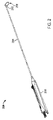
図2は、左心耳を閉鎖するために使用され得る閉鎖装置(200)の1つの例示的な変形例を図示する。スネアループアセンブリ(202)、細長い本体(204)、及びハンドル(206)を示す。上述したように、ハンドル(206)は、閉じた構成と、開いた展開構成と、引き込み構成との間でスネアループアセンブリ(202)を動かすために、細長い本体(204)を介してスネアループアセンブリ(202)を制御及び作動させるために使用され得る。開いた構成にあるとき、スネアループアセンブリ(202)及び細長い本体(204)は、(例えば、スネアループアセンブリ(202)及び細長い本体(204)がループ(208)内に配置された組織を完全に取り囲み得るように)連続的なループ(208)を形成し得る。開いた構成から閉じた構成に動かされたとき、スネアループアセンブリ(202)の一部または全部が細長い本体(204)内に引っ込められるにつれて、ループ(208)のサイズが低減され得る。最後に、引き込み位置において、ループ(208)(例えば、スネア及び保持部材)は、細長い本体(204)内に完全に提供され得る。代替的に、引き込み位置において、ループ(208)の実質的な部分は、ループ(208)の小部分が細長い本体(204)の外側に留まるように、細長い本体内に提供され得る。 FIG. 2 illustrates one exemplary variation of a closure device (200) that may be used to close the left atrial appendage. Shown are snare loop assembly (202), elongated body (204), and handle (206). As noted above, handle (206) is provided through elongate body (204) to move snare loop assembly (202) between a closed configuration, an open deployed configuration, and a retracted configuration. (202) to control and operate. When in the open configuration, snare loop assembly (202) and elongated body (204) may fully penetrate tissue (eg, where snare loop assembly (202) and elongated body (204) are disposed within loop (208)). A continuous loop (208) may be formed (encircling). When moved from an open configuration to a closed configuration, the size of loop (208) may be reduced as part or all of snare loop assembly (202) is retracted within elongated body (204). Finally, in the retracted position, loop (208) (eg, snare and retention member) may be provided entirely within elongated body (204). Alternatively, in the retracted position, a substantial portion of loop (208) may be provided within elongate body such that a minor portion of loop (208) remains outside elongate body (204).
本明細書に記載される閉鎖装置は、最小侵襲的(例えば、胸郭の上、下、または通した小切開を通して、肋軟骨または剣状突起内の切開を通して、ポートを介して、血管系を介して等)かつ外科的(例えば、胸骨正中切開術、ミニ胸骨切開術、開胸術、胸腔鏡検査等)アプローチを使用して、左心耳に前進するのに好適であり得る。 The closure devices described herein are minimally invasive (e.g., through a small incision above, below, or through the ribcage, through an incision in the costal cartilage or xiphoid process, through a port, through the vasculature). sternotomy, etc.) and surgical (eg, median sternotomy, ministernotomy, thoracotomy, thoracoscopy, etc.) approaches may be preferred to advance the left atrial appendage.
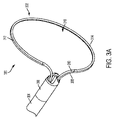
図3Aは、スネアループアセンブリ(302)及び先端部(306)を有する細長い本体(304)を備える閉鎖装置(300)の例示的変形例の遠位区分を示す。図3Aに示すように、スネアループアセンブリ(302)は、スネア(308)、縫合糸ループ(310)、及び保持部材(312)を備え得、スネアループアセンブリ(302)の少なくとも一部分が細長い本体(304)から(例えば、先端部(306)を介して)延在するように、細長い本体(304)に対して配設され得る。スネアループアセンブリ(302)は、図3Aに開いた構成で示されており、細長い本体(304)から延在しているスネアループアセンブリ(302)の一部分は、ループ(314)を通る穴部(316)を有するループ(314)を形成し得る。ループ(314)及び対応する穴部(316)は、スネアループアセンブリ(302)の1つ以上の構成要素(例えば、スネア)によって画定され得、かつ左心耳等の組織を包囲するのに適し得る。一般に、スネア(308)は、スネアループアセンブリ(302)を開閉するために使用され得る。いくつかの例では、保持部材(312)は、縫合糸ループ(310)及びスネア(308)を解放可能に連結するように構成され得、縫合糸ループ(310)への十分な力の適用時に、縫合糸ループ(310)をスネアループアセンブリ(302)から解放するように構成され得る。 FIG. 3A shows the distal section of an exemplary variation of a closure device (300) comprising an elongated body (304) having a snare loop assembly (302) and a tip (306). As shown in FIG. 3A, snare loop assembly (302) may comprise snare (308), suture loop (310), and retention member (312), wherein at least a portion of snare loop assembly (302) comprises an elongated body ( 304) (eg, via tip (306)). Snare loop assembly (302) is shown in an open configuration in FIG. 3A with a portion of snare loop assembly (302) extending from elongated body (304) extending through a hole (314) through loop (314). 316) may form a loop (314). Loops (314) and corresponding holes (316) may be defined by one or more components (e.g., snare) of snare loop assembly (302) and may be suitable for surrounding tissue such as the left atrial appendage. . In general, snare (308) may be used to open and close snare loop assembly (302). In some examples, retention member (312) may be configured to releasably couple suture loop (310) and snare (308) such that upon application of sufficient force to suture loop (310), a , to release suture loop (310) from snare loop assembly (302).
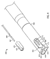
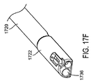
スネアループアセンブリは、スネアループの遠位部分が細長い本体の先端部から解放されることを可能にして、スネアループが先端部の管腔内に引き込まれることを可能にするシャトルをさらに備え得る。スネアループを先端部内に引き込むことにより、装置のプロファイルが減少し、本体からの装置の取り外しが改善される。例えば、スネアを細長い本体内に引き込むことにより、シャトルが先端部から解放された後に装置が体から除去されるときに、スネアが組織に引っかかる、かつ/または組織を損傷することが防止され得る。シャトルは、スネアループを先端部に解放可能に接続するように機能し得る。ユーザは、ハンドルを介したシャトルの解放を制御し得る。図5Aは、先端部(503)、シャトル(516)、ならびに近位部分(512)及び遠位部分(514)を備える引き込み可能なスネアを備える細長い本体(502)を有する閉鎖装置(500)の斜視図である。シャトル(516)は、スネアの遠位部分(514)に接続され得、かつ細長い本体(502)の先端部(503)に解放可能に連結され得る。先端部(503)を備えるように図示されているが、細長い本体(502)は必要ではない。先端部を使用しない変形例では、シャトルは、細長い本体の側壁に(例えば、細長い本体の遠位部分または端部で)連結され得る。 The snare loop assembly may further comprise a shuttle that allows the distal portion of the snare loop to be released from the tip of the elongated body to allow the snare loop to be drawn into the lumen of the tip. Retracting the snare loop into the tip reduces the profile of the device and improves removal of the device from the body. For example, retracting the snare into the elongated body may prevent the snare from catching and/or damaging tissue when the device is removed from the body after the shuttle is released from the tip. A shuttle may function to releasably connect the snare loop to the tip. A user may control the release of the shuttle via the handle. FIG. 5A shows a closure device (500) having an elongated body (502) with a tip (503), a shuttle (516), and a retractable snare with a proximal portion (512) and a distal portion (514). It is a perspective view. A shuttle (516) may be connected to the snare distal portion (514) and may be releasably coupled to the distal end (503) of the elongated body (502). Although shown with a tip (503), an elongated body (502) is not required. In variations that do not use a tip, the shuttle can be coupled to the sidewall of the elongate body (eg, at the distal portion or end of the elongate body).
閉塞装置が心膜腔等の閉じ込められた本体空間を通して前進されると、これらの狭い空間内もしくは中を通るスネアループアセンブリの前進もしくは操作により、細長い本体から突出するスネアの端部等のスネアの一部分が、スネアの他の部分よりもかなりの程度まで曲がり、かつ湾曲する場合がある。スネアループを形成するために、スネアは、細長い本体の先端部を離れるときに曲がる場合がある。スネアの曲がりは、スネアの先端部に対する摩擦によって細長い本体に対してスネアに接続された構成要素内にずれまたは傾斜を誘発し得る。 When the occlusion device is advanced through a confined body space such as the pericardial space, advancement or manipulation of the snare loop assembly within or through these narrow spaces causes the snare, such as the end of the snare, to protrude from the elongated body. Some parts may bend and curve to a greater extent than other parts of the snare. To form a snare loop, the snare may bend as it leaves the distal end of the elongated body. Bending of the snare can induce slippage or tilting in components connected to the snare relative to the elongated body due to friction against the tip of the snare.
例えば、スネアに接続された従来のシャトルは、スネアの曲がりによって生成された力のために、先端部の凹部から上方にずれるか、または傾斜することがある。こうしてスネアの曲がり部分が先端部の側壁に接触する不均一な干渉が生成される。その結果、摩擦力は、先端部に対するシャトルの位置ずれを生じさせ得、装置の組み立て及び動作を困難にし得る。さらに、いくつかの例では、スネアループアセンブリを閉じ込められた空間内で曲げるか、または操作することにより、スネアと先端部との間に挟み込まれる可能性のある、組織からの望ましくない干渉が生じ得る。したがって、本明細書に記載される装置は、スネアが細長い本体に対してこすれるか、または当接することなく自由に湾曲することを可能にするように構成され得、干渉、位置ずれ及び組織挟み込みを低減することができる。 For example, a conventional shuttle connected to a snare can drift upward or tilt out of the tip recess due to the forces created by the bending of the snare. This creates an uneven interference where the bend of the snare touches the side walls of the tip. As a result, frictional forces can cause misalignment of the shuttle relative to the tip, making assembly and operation of the device difficult. Additionally, in some instances, bending or manipulating the snare loop assembly within the confined space creates unwanted interference from tissue that can become pinched between the snare and the tip. obtain. Accordingly, the devices described herein can be configured to allow the snare to bend freely without rubbing or abutting against the elongated body, reducing interference, misalignment and tissue pinching. can be reduced.
さらに、従来のスネアループは、ループ内に配設された組織の周りからスネアループをより容易に取り外すことができるように、スネアループの遠位部分を先端部から取り外すことができるという点で解放可能であり得る。しかし、スネアループの遠位部分の解放後、組織を取り囲んでいたスネアの一部分及びシャトルは、細長い本体の外部に露出したままである。スネア及びシャトルのこの露出部分は、閉鎖装置が標的組織から離れて動かされるときに、解剖学的特徴部または縫合糸と相互作用し、かつこれら上で引っかかる場合がある。したがって、本明細書の下に記載される装置は、スネアの一部分またはシャトルが露出したままでないように、スネア及びシャトルが細長い本体内に完全に引き込むことを可能にするように構成され得る。他の変形例では、本明細書に記載される装置は、スネアループの略全体(例えば、処置中に露出したスネアループの大部分、露出したスネアループの2/3、露出したスネアループの5/6等)、よってスネアが、シャトル及びスネアの小部分が細長い本体の外側に残存するために、細長い本体内に引き込むことを可能にするように構成され得る。 Additionally, conventional snare loops are liberating in that the distal portion of the snare loop can be removed from the tip so that the snare loop can be more easily removed from around tissue disposed within the loop. can be possible. However, after release of the distal portion of the snare loop, the portion of the snare that surrounded the tissue and the shuttle remain exposed to the exterior of the elongated body. This exposed portion of the snare and shuttle may interact with and catch on anatomical features or sutures as the closure device is moved away from the target tissue. Accordingly, the devices described herein below can be configured to allow the snare and shuttle to be fully retracted into the elongated body such that no portion of the snare or shuttle remains exposed. In other variations, the devices described herein can be used to cover substantially the entire snare loop (e.g., most of the snare loops exposed during the procedure, 2/3 of the snare loops exposed, 5 of the snare loops exposed). /6 etc.), thus allowing the snare to be retracted into the elongated body so that the shuttle and a small portion of the snare remain outside the elongated body.
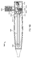
細長い本体及びスネアループアセンブリを有することに加えて、本明細書で記載される閉鎖装置は、典型的には、細長い本体及び/またはスネアループアセンブリの操作及び前進を制御するための1つ以上の機構を備える。例えば、ハンドルまたは他の制御機構(例えば、外科用マスタースレーブロボットシステム)を使用して、細長い本体を通してスネアループアセンブリを制御及び作動させ得る。ハンドルもしくは他の制御機構は、送達もしくは「閉じた」構成と、展開もしくは「開いた」構成との間で、及びその逆でスネアループアセンブリを変更し得る。さらに、ハンドルまたは他の制御機構は、スネアループアセンブリを引き込まれた構成へと動かすことができる。 In addition to having an elongated body and a snare loop assembly, the closure devices described herein typically include one or more probes for controlling manipulation and advancement of the elongated body and/or snare loop assembly. It has a mechanism. For example, a handle or other control mechanism (eg, a surgical master-slave robotic system) may be used to control and actuate the snare loop assembly through the elongated body. A handle or other control mechanism may change the snare loop assembly between a delivered or "closed" configuration and a deployed or "open" configuration and vice versa. Additionally, a handle or other control mechanism can move the snare loop assembly to the retracted configuration.
スネアループアセンブリを閉じた構成で配置することにより、スネアループアセンブリの標的位置への低プロファイル前進を可能にし得、かつ/またはスネアループアセンブリが標的組織の周りで閉じることを可能にし得る。反対に、スネアループアセンブリを開いた構成で配置することにより、スネアループアセンブリを1つ以上の標的組織の周りに配置することを可能にし得、かつ/またはスネアループアセンブリがスネアループアセンブリによって先に閉じられた1つ以上の標的組織を解放することを可能にし得る。したがって、本明細書に記載される装置は、スネアループアセンブリからの縫合糸ループの解放、ならびにスネアの解放及び引き込みを制御するハンドル及び/または1つ以上の他の制御機構をさらに含み得る。閉鎖装置は、シャトルの先端部からの解放前に、操作者がスネア及びシャトルを引き込むことを防止する機構をさらに含み得る。 Placing the snare loop assembly in a closed configuration may allow low profile advancement of the snare loop assembly to the target location and/or may allow the snare loop assembly to close around the target tissue. Conversely, placing the snare loop assembly in an open configuration may allow the snare loop assembly to be placed about one or more target tissues and/or the snare loop assembly may be preceded by the snare loop assembly. It may allow one or more closed target tissues to be released. Accordingly, the devices described herein may further include a handle and/or one or more other control mechanisms that control release of the suture loop from the snare loop assembly and release and retraction of the snare. The closure device may further include a mechanism that prevents an operator from retracting the snare and shuttle prior to release from the tip of the shuttle.
閉鎖装置は、下により詳細に記載されるように、1つ以上の追加の特徴を含み得る。いくつかの変形例では、面取り部は、細長い本体の遠位部分に追加され得、細長い本体の遠位部分は、先端部により覆われているか、または部分的に覆われており、狭い公差のために先端部に亀裂が生じるのを防止し得る。他の変形例では、先端部の高さを細長い本体に対して増加させて、先端部に対する応力を低減し、隙間を増大させ、かつ細長い本体が先端部内で歪むための余地を提供し得る。よって、閉鎖装置の製造可能性及び信頼性が改善される。これら及び他の特徴を、以下により詳細に記載しよう。本明細書に記載される閉鎖装置は、これらの特徴と、参照により記載及び/または組み込まれる他の特徴との任意の組み合わせを含み得ることは、評価されるべき点である。 A closure device may include one or more additional features, as described in more detail below. In some variations, a chamfer may be added to a distal portion of the elongate body, the distal portion of the elongate body being covered or partially covered by a tip and having a narrow tolerance. Therefore, it is possible to prevent the tip from cracking. In other variations, the height of the tip may be increased relative to the elongated body to reduce stress on the tip, increase clearance, and provide room for the elongated body to flex within the tip. Manufacturability and reliability of the closure device are thus improved. These and other features will be described in more detail below. It should be appreciated that the closure devices described herein may include any combination of these features and other features described and/or incorporated by reference.
本明細書に記載される閉鎖装置は、「Tissue Ligation Devices and Methods Therefor」と題された、2014年3月3日に出願された、米国特許出願第14/195,797号に記載されているもの等の任意の好適な要素または要素の組み合わせを含み得、その内容は、その全体が参照により本明細書に組み込まれる。本明細書に記載される閉鎖装置の個々の構成要素を、以下により詳細に記載しよう。 The closure devices described herein are described in U.S. Patent Application Serial No. 14/195,797, filed March 3, 2014, entitled "Tissue Ligation Devices and Methods Therefor." any suitable element or combination of elements, the contents of which are incorporated herein by reference in their entirety. The individual components of the closure devices described herein will be described in greater detail below.
細長い本体
上に簡単に述べたように、本明細書に記載される閉鎖装置は、概して、細長い本体を備え得る。細長い本体は、細長い本体を介したスネアループアセンブリの制御を可能にしながら、スネアループアセンブリの遠位端部及びハンドルまたは作動機構を接続し得る。具体的には、スネアループアセンブリ構成要素のうちのいくつかの少なくとも一部分は、細長い本体内に収容され得、かつ細長い本体を介してハンドルに接続され得る。いくつかの変形例では、細長い本体の少なくとも一部分は、可撓性であり得、これが、細長い本体が体を通るのを促進するのを助け得る。
Elongated Body As briefly mentioned above, the closure devices described herein may generally comprise an elongated body. An elongated body may connect the distal end of the snare loop assembly and a handle or actuation mechanism while allowing control of the snare loop assembly via the elongated body. Specifically, at least a portion of some of the snare loop assembly components may be housed within the elongated body and connected to the handle via the elongated body. In some variations, at least a portion of the elongated body may be flexible, which may help facilitate passage of the elongated body through the body.
細長い本体は、概して、その遠位端部に先端部を備え得る。いくつかの変形例では、細長い本体の先端部は、細長い本体とは別に形成され得、かつ装置の組み立て中に細長い本体に取り付けられ得る。例えば、いくつかの変形例では、先端部及び細長い本体は、滑り嵌め及び/または接着剤によって取り付けられ得る。他の変形例では、先端部分は、単一の装置として細長い本体と一体的に形成され得る。先端部分は、閉鎖装置のためのいくつかの有用な機能を果たし得る。いくつかの例では、先端部は、非外傷性であるように構成され得、これは、細長い本体の近位端部が体内で動かされたときに組織に損傷を与えるリスクを低減するよう作用し得る。他の例では、先端部は、下により詳細に記載するように、スネアの特定の部分が、細長い本体に対して他の部分を適所に保持しながら、細長い本体の管腔を通過することを可能にし得る。 The elongated body may generally include a tip at its distal end. In some variations, the distal end of the elongated body may be formed separately from the elongated body and attached to the elongated body during assembly of the device. For example, in some variations the tip and elongated body may be attached by a slip fit and/or adhesive. In other variations, the tip portion may be integrally formed with the elongated body as a single device. The tip portion can serve several useful functions for the closure device. In some examples, the tip can be configured to be atraumatic, which acts to reduce the risk of tissue damage when the proximal end of the elongated body is moved within the body. can. In other examples, the tip is designed to allow certain portions of the snare to pass through the lumen of the elongated body while holding other portions in place relative to the elongated body, as described in more detail below. can make it possible.
先端部は、細長い本体と同じ数の管腔を有し得るが、そうである必要はない。実際、いくつかの変形例では、先端部は、細長い本体の1つ以上の管腔を2つ以上の副管腔へと分割し得る。他の変形例では、先端部は、細長い本体の1つ以上の管腔のサイズまたは形状を変えてもよい。 The tip can have the same number of lumens as the elongated body, but need not. Indeed, in some variations, the tip may divide one or more lumens of the elongated body into two or more sub-lumens. In other variations, the tip may change the size or shape of one or more lumens of the elongated body.
細長い本体は、異なる特性、例えば、異なる直径、断面形状、剛性、材料等を有する様々な区分または部分を備えることができ、閉鎖装置の運転可能性及び操縦可能性を高め得る。 The elongated body can comprise various sections or portions having different properties, such as different diameters, cross-sectional shapes, stiffness, materials, etc., which can enhance the drivability and steerability of the closure device.
細長い本体は、任意の好適な長さを含んでもよく、細長い本体の長さは、行われる処置の種類に応じて変り得る。細長い本体は、任意の好適な材料、例えば、1つ以上のポリマー(例えば、ポリエーテルブロックアミド、ポリエチレン、シリコーン、ポリ塩化ビニル、ラテックス、ポリウレタン、PTFE、ナイロン等)から作製され得る。最小侵襲的処置の間、細長い本体は、装置が外科的処置において使用されるときよりも、標的組織に到達するために体を通ってさらなる距離を動かなければならない場合がある。よって、装置を最小侵襲的処置において使用するときには、より長い細長い本体を使用することが望ましく、装置を外科的処置において使用するときには、より短い細長い本体を使用することが望ましい場合がある。 The elongated body may include any suitable length, and the length of the elongated body may vary depending on the type of procedure being performed. The elongate body can be made from any suitable material, such as one or more polymers (eg, polyether block amide, polyethylene, silicone, polyvinyl chloride, latex, polyurethane, PTFE, nylon, etc.). During minimally invasive procedures, the elongated body may have to travel a greater distance through the body to reach the target tissue than when the device is used in a surgical procedure. Thus, it may be desirable to use longer elongated bodies when the device is used in minimally invasive procedures, and shorter elongated bodies when the device is used in surgical procedures.
さらに、細長い本体は、例えば、円形、楕円形、D字形、三角形等の任意の好適な断面形状を含んでもよい。いくつかの実施形態では、細長い本体の断面形状は、その長さに沿って変り得る。いくつかの変形例では、細長い本体は、複数の部分を有するものとして記載され得、各部分は、特定の断面形状に対応している。例えば、細長い本体は、第1の断面形状(例えば、円形)を有する近位部分と、第2の断面形状(例えば、D字形)を有する遠位部分と、を備え得る。当然ながら、細長い本体は、任意の好適な数の部分、例えば、2つ、3つ、または4つの部分を備えることができ、各部分の長さは、他の部分と同じであるか、または異なるとしてもよい。 Additionally, the elongated body may include any suitable cross-sectional shape, such as circular, oval, D-shaped, triangular, and the like. In some embodiments, the cross-sectional shape of the elongate body can vary along its length. In some variations, the elongated body may be described as having multiple sections, each section corresponding to a particular cross-sectional shape. For example, the elongated body may comprise a proximal portion having a first cross-sectional shape (eg circular) and a distal portion having a second cross-sectional shape (eg D-shaped). Of course, the elongated body may comprise any suitable number of sections, for example 2, 3 or 4 sections, each section being the same length as the others, or may be different.
細長い本体はまた、任意の好適な外径を備えてもよく、いくつかの例では、細長い本体の外径も、その長さに沿って変り得る。例えば、最小侵襲的処置の間に閉鎖装置が使用される例では、13フレンチ経皮チューブ内を通り得るように、細長い本体の外径を制限することが望ましい場合がある。 The elongated body may also comprise any suitable outer diameter, and in some examples the outer diameter of the elongated body may also vary along its length. For example, in instances where a closure device is used during minimally invasive procedures, it may be desirable to limit the outer diameter of the elongated body so that it can pass within a 13 French percutaneous tube.
細長い本体は、異なる直径または異なる断面形状を含む細長い本体の部分を接続する1つ以上の移行部をさらに備え得る。これらの移行部は、任意の好適な長さを有し得る。 The elongated body may further comprise one or more transitions connecting portions of the elongated body that include different diameters or different cross-sectional shapes. These transitions can have any suitable length.
管腔
本明細書に記載される細長い本体は、任意の好適な数の管腔を有し得る。本明細書で使用される場合、「管腔」は、細長い本体もしくは閉鎖装置の他の部分の長さを通って、もしくは部分的に通って、(例えば、ハンドルを通って)延在している任意のボアもしくは通路を指し得る。管腔が全体的に含まれる必要はない(すなわち、管腔は、1つ以上のスロット、切り込み、間隙、または管腔の長さの一部もしくは全部に沿った他の開口部を含み得る)ことが理解されるべきである。細長い本体は、1つ、2つ、3つ、4つ、または5つ以上の管腔を備え得る。管腔のうちのいくつかまたは全部は、細長い本体全体を通って(すなわち、細長い本体の近位端部から細長い本体の遠位端部まで)延在し得る。他の管腔は、細長い本体の一部分のみを通過してもよい(例えば、細長い本体に沿って一方の端部から中間点へと、または細長い本体に沿って2つの中間点の間)。
Lumens The elongate bodies described herein can have any suitable number of lumens. As used herein, a "lumen" extends through, or partially through, the length of another portion of the elongated body or closure device (e.g., through the handle). can refer to any bore or passageway in The lumen need not be wholly contained (ie, the lumen may include one or more slots, notches, gaps, or other openings along some or all of the length of the lumen) should be understood. The elongated body may comprise 1, 2, 3, 4, 5 or more lumens. Some or all of the lumens may extend through the entire elongate body (ie, from the proximal end of the elongate body to the distal end of the elongate body). Other lumens may pass through only a portion of the elongate body (eg, from one end to an intermediate point along the elongate body, or between two intermediate points along the elongate body).
スネアループアセンブリの様々な構成要素は、細長い本体の任意の管腔または複数の管腔内に収容され得る。例えば、いくつかの変形例では、スネアループアセンブリの構成要素の全てを単一の管腔内に収容してもよい。他の変形例では、スネアループアセンブリの異なる部分は、異なる管腔内に少なくとも部分的に収容され得る。例えば、縫合糸ループの自由端部は、第1の管腔を通ってハンドルに移動し得、スネアの自由端部は、第2の管腔を通ってハンドルに移動し得る。いくつかの変形例では、細長い本体内に収容された余分な縫合糸がある場合があり、この余分な縫合糸は、任意の好適な管腔内に収容され得る。例えば、余分な縫合糸は、縫合糸ループの自由端部と同じ管腔内に、スネアの自由端部と同じ管腔内に、または全く異なる管腔内に保持されてもよい。 The various components of the snare loop assembly may be housed within any lumen or multiple lumens of the elongated body. For example, in some variations all of the snare loop assembly components may be housed within a single lumen. In other variations, different portions of the snare loop assembly may be at least partially housed within different lumens. For example, the free end of the suture loop may travel through a first lumen to the handle and the free end of the snare may travel through a second lumen to the handle. In some variations, there may be excess suture contained within the elongated body, which may be contained within any suitable lumen. For example, the excess suture may be held in the same lumen as the free end of the suture loop, in the same lumen as the free end of the snare, or in an entirely different lumen.
本明細書に示す管腔は、細長い本体内の特定の位置に図示されているが、管腔は、細長い本体内の任意の位置に位置付けられ得る(すなわち、それらの中心が動かされ、それらの位置がずれる可能性がある)が、突き抜けを防止するために管腔の間の最小壁厚を維持することが望ましい場合がある。例えば、いくつかの変形例では、細長い本体が押し出し成形された後、もしくは別様に製造された後に、細長い本体を加熱して、閉鎖装置に他の要素を取り付けるか、挿入するか、もしくは結合する必要がある場合がある。細長い本体を加熱することにより、管腔の位置がずれるか、またはサイズが変更されることがある。いくつかの例では、2つの管腔を分離する材料の一部分は、管腔が収束するか、または別様に一緒になって2つではなく1つの管腔を形成するように切断してもよい。 Although the lumens shown herein are illustrated at particular locations within the elongated body, the lumens may be positioned at any location within the elongated body (i.e., their centers may be moved and their misalignment), it may be desirable to maintain a minimum wall thickness between lumens to prevent punch-through. For example, in some variations, the elongated body is heated after the elongated body has been extruded or otherwise manufactured to attach, insert, or bond other elements to the closure device. you may need to. Heating the elongated body may displace or resize the lumen. In some instances, the portion of material separating the two lumens may be cut such that the lumens converge or otherwise come together to form one lumen rather than two. good.
この突き抜けの可能性を低減するために、押し出し成形及び/または加熱中の管腔間の最小間隔を維持することが望ましい場合がある。さらに、上に記載されるように、いくつかの変形例では、細長い本体の一部分は、細長い本体の一部分を切断、シェービング、スカイビング、または別様に除去することによって作成され得るD字形断面を備え得る。これらの変形例では、管腔間の最小壁厚を維持することにより、細長い本体が切断されてD字形を形成するときに管腔が加熱中にずれて切断されるのを防止することができる。したがって、いくつかの変形例では、管腔間に少なくとも約0.005’’(0.127mm)の壁厚を維持することが望ましい場合がある。 To reduce the likelihood of this punch-through, it may be desirable to maintain a minimum spacing between lumens during extrusion and/or heating. Further, as described above, in some variations the portion of the elongate body has a D-shaped cross-section that can be created by cutting, shaving, skiving, or otherwise removing a portion of the elongate body. be prepared. In these variations, maintaining a minimum wall thickness between lumens can prevent the lumens from being cut out of alignment during heating when the elongated body is cut to form the D-shape. . Therefore, in some variations it may be desirable to maintain a wall thickness of at least about 0.005'' (0.127 mm) between lumens.
さらに、いくつかの変形例では、管腔は、管腔の内面と管腔内に収容された構成要素との間の摩擦力を低減するように設計された内張りまたはコーティングを備え得る。細長い本体を作製するために必要とされる管腔の小サイズ、それらの相対的な位置、使用される材料、及び精度は、異なるロット及び/または異なる製造業者の間で製造のばらつき(例えば、管腔の内側の異なる摩擦特性)の原因になり得る。こうしたばらつきは、ユーザ体験の一貫性を損なう可能性があり、閉鎖装置への不満及び/または不適切な使用を招く可能性がある。例えば、縫合糸管腔の内面と縫合糸との間の摩擦力が変化する場合、ユーザは、縫合糸を締め付けるために、装置が使用されるたびに異なる量の力を加えることを要求され得る。これにより、組織の周りでの縫合糸の過度の締め付け、または過少の締め付けの原因となる可能性がある。したがって、いくつかの実施形態では、縫合糸管腔は、摩擦低減内張りまたはコーティング(例えば、ポリテトラフルオロエチレン(PTFE))を備え得る。細長い本体の管腔のいずれか及び/または全部に摩擦低減内張りを含めることが望ましい場合があり、そうすることにより、より一貫性のある予測可能なユーザ体験が得られる可能性がある。 Additionally, in some variations the lumen may comprise a lining or coating designed to reduce frictional forces between the inner surface of the lumen and components housed within the lumen. The small size of the lumens, their relative positions, the materials used, and the precision required to create the elongated body can result in manufacturing variability (e.g., between different lots and/or different manufacturers). different frictional properties inside the lumen). Such variations can lead to an inconsistent user experience and can lead to dissatisfaction and/or improper use of the closure device. For example, if the frictional force between the inner surface of the suture lumen and the suture varies, the user may be required to apply different amounts of force each time the device is used to tighten the suture. . This can cause the suture to over-tighten or under-tighten around the tissue. Accordingly, in some embodiments, the suture lumen may include a friction-reducing liner or coating (eg, polytetrafluoroethylene (PTFE)). It may be desirable to include friction-reducing linings in any and/or all of the lumens of the elongated body, and doing so may result in a more consistent and predictable user experience.
先端部
いくつかの変形例では、細長い本体の先端部を細長い本体とは別に形成してもよく、細長い本体の遠位端部上で先端部をスライドさせることによって、先端部を細長い本体に連結し得る。また、図6A及び6Bは、閉鎖装置(600)の細長い本体(604)及び先端部(602)の変形例の側面図及び斜視図である。この変形例では、先端部(602)及び細長い本体(604)は、細長い本体(604)が先端部(602)の空洞(610)内に固定される滑り嵌めを提供するように構成されている。細長い本体(604)の遠位端部分(606)は、角面取り部(608)を備える場合があり、角面取り部(608)は、細長い本体(604)の遠位端部分(606)と応力が集中し得る先端部(602)との間の接点を除去することによって、先端部(602)が亀裂または損傷するのを防止する助けとなり得る。
Tip In some variations, the tip of the elongated body may be formed separately from the elongated body and coupled to the elongated body by sliding the tip over the distal end of the elongated body. can. 6A and 6B also show side and perspective views of variations of elongated body (604) and tip (602) of closure device (600). In this variation, tip (602) and elongated body (604) are configured to provide a slip fit in which elongated body (604) is secured within cavity (610) of tip (602). . A distal end portion (606) of the elongated body (604) may comprise a corner chamfer (608), the corner chamfer (608) being in contact with the distal end portion (606) of the elongated body (604). Eliminating the contact points between tip (602) that may congregate may help prevent tip (602) from cracking or breaking.
1つの特定の変形例では、細長い本体(604)の最外径は0.148インチ±0.002インチ(3.7592mm±0.0508mm)であり得、遠位端部(606)の高さは、0.096インチ±0.002インチ(0.24384mm±0.0508mm)であり得、先端部の空洞を画定する先端部(602)の内径は、0.148インチ+0.002/-0.001インチ(3.7592mm+0.0508/-0.0254mm)であり得、先端部の内側高さは、0.099インチ±0.002インチ(2.5146mm±0.0508mm)であり得る。 In one particular variation, the outermost diameter of elongated body (604) can be 0.148 inches ± 0.002 inches (3.7592 mm ± 0.0508 mm) and the height of distal end (606) can be 0.096 inches ± 0.002 inches (0.24384 mm ± 0.0508 mm) and the inner diameter of the tip (602) defining the tip cavity is 0.148 inches + 0.002/-0 001 inch (3.7592 mm + 0.0508/-0.0254 mm) and the inner height of the tip can be 0.099 inch ± 0.002 inch (2.5146 mm ± 0.0508 mm).
いくつかの変形例では、いったん細長い本体の遠位端部分が先端部の空洞内に配置されると、細長い本体の外面と先端部の内面(すなわち、空洞の面)との間に間隙または隙間が形成され得る。細長い本体と先端部との間に形成された間隙または隙間は、細長い本体と先端部との間の一貫性のある信頼可能な収まりを提供する助けとなり得、かつ細長い本体が先端部内で歪むためのより大きい空間を提供することによって、先端部上にかかる応力を低減し得る。いくつかの変形例では、間隙または隙間は、先端部の内側(及びいくつかの変形例では、外径)を増加させることによって形成することができ、他の変形例では、例えば、D字形先端部を使用する場合、先端部の高さが増加され得る間、先端部の直径を一定に保つことができる。 In some variations, once the distal end portion of the elongated body is positioned within the cavity of the tip, there is a gap or gap between the outer surface of the elongated body and the inner surface of the tip (i.e., the surface of the cavity). can be formed. A gap or gap formed between the elongated body and the tip can help provide a consistent and reliable fit between the elongated body and the tip, and as the elongated body flexes within the tip. By providing more space for the tip, the stress on the tip may be reduced. In some variations, the gap or clearance can be formed by increasing the inside (and in some variations, the outside diameter) of the tip, in other variations, e.g., a D-shaped tip When using a section, the diameter of the tip can be kept constant while the height of the tip can be increased.
また、図7A及び7Bは、先端部(702)の空洞内に位置付けられた細長い本体(704)の変形例の断面図である。図7A及び7Bに示すように、先端部(702)及び細長い本体(704)は、それらの間に隙間(712)を有し得る。細長い本体(704)は、第1の管腔(706)、第2の管腔(708)、第3の管腔(710)、及び角面取り部(714)を備え得る。先端部(702)及び細長い本体(704)の少なくとも一部分(例えば、遠位部分)は、各々が高さ(703、705)を有するD字形断面形状を有し得る。いくつかの変形例では、先端部(702)の高さ(703)は、先端部と細長い本体との間に(例えば、先端部(702)の平面または直線底面と細長い本体部(704)との間に)隙間(712)が形成されるように、細長い本体(704)の遠位部分の高さ(705)よりも大きい場合がある。先端部は、任意の好適な高さを有し得るが、閉鎖処置中に閉鎖装置と共に使用され得る他の構成要素、例えば、ガイドワイヤ及び/またはガイド/送達カニューレを妨害しないように、先端部をサイズ決め及び構成することが有用であり得る。例えば、いくつかの変形例では、先端部の高さは、先端部及びガイドワイヤが送達カニューレの管腔内に収まり(例えば、積み重ね)得るように選択することができる。よって、いくつかの変形例では、ガイドワイヤの直径と組み合わされた先端部の高さ及び厚さは、送達カニューレの管腔の直径未満、例えば、約0.174インチの管腔直径を有する13フレンチ送達カニューレであり得る。 7A and 7B are also cross-sectional views of variations of elongate body (704) positioned within a cavity of tip (702). As shown in FIGS. 7A and 7B, tip (702) and elongated body (704) may have a gap (712) therebetween. Elongated body (704) may comprise a first lumen (706), a second lumen (708), a third lumen (710), and a corner chamfer (714). Tip (702) and at least a portion (eg, distal portion) of elongated body (704) may have a D-shaped cross-sectional shape, each having a height (703, 705). In some variations, the height (703) of the tip (702) is between the tip and the elongate body (e.g., between the flat or straight bottom surface of the tip (702) and the elongate body (704)). may be greater than the height (705) of the distal portion of the elongated body (704) such that a gap (712) is formed between the two. The tip may have any suitable height, but the tip should be raised so as not to interfere with other components that may be used with the closure device during the closure procedure, such as the guidewire and/or guide/delivery cannula. It may be useful to size and configure the . For example, in some variations, the height of the tip can be selected so that the tip and guidewire can fit (eg, stack) within the lumen of the delivery cannula. Thus, in some variations, the height and thickness of the tip combined with the guidewire diameter is less than the lumen diameter of the delivery cannula, e.g., having a lumen diameter of about 0.174 inches. It can be a French delivery cannula.
例えば、いくつかの変形例では、約0.115インチ(2.921mm)~約0.125インチ(3.175mm)の範囲の外側高さを有する先端部(702)を利用することが有用であり得る。さらに、上述したように、先端部及び細長い本体の遠位端部の直径/高さは、それらの間に好適な間隙または隙間、例えば、約0.001インチ(0.0254mm)と約0.012インチ(0.305mm)との間の隙間が生成されるように選択することができる。例えば、いくつかの変形例では、先端部の外側高さは、約0.120’’(3.048mm)であり得、先端部(702)の内側高さ(703)は、約0.099インチ±0.002インチ(2.515mm±0.0508mm)と0.104インチ±0.002インチ(2.642mm±0.0508mm)との間であり得、細長い本体の遠位端部の高さは、約0.094インチ(2.388mm)と約0.098インチ(2.489mm)との間であり得る。例えば、図7Aに示すように、いくつかの変形例では、先端部(702)の高さ(703)は、約0.106インチ(2.692mm)であり得、細長い本体(704)の遠位端部が先端部(702)内に位置付けられたときに約0.012インチ(0.330mm)の隙間(712)高さを提供し得る。他の変形例、例えば、図7Bに示す変形例では、先端部(702)の高さ(703)は、約0.104インチ(2.642mm)であり得、細長い本体(704)に対して約0.008インチ(0.2032mm)の隙間(712)高さを提供し得る。前述は、単なる例であり、約0.001インチ(0.0254mm)と約0.012インチ(0.305mm)との間の隙間を生じる細長い本体の先端部と遠位端部との高さの任意の組み合わせ(例えば、上に含まれる範囲内の値から選択された各々についての高さの任意の組み合わせ)を使用することができる。 For example, in some variations it may be useful to utilize a tip (702) having an outer height ranging from about 0.115 inches (2.921 mm) to about 0.125 inches (3.175 mm). could be. Further, as noted above, the diameter/height of the tip and the distal end of the elongated body may be a suitable gap or clearance therebetween, eg, about 0.001 inches (0.0254 mm) and about 0.001 inches (0.0254 mm) and about 0.001 inch (0.001 inch). A gap of between 0.12 inches (0.305 mm) can be selected to be created. For example, in some variations, the outer height of tip (702) may be about 0.120'' (3.048 mm) and the inner height (703) of tip (702) may be about 0.099 mm. The height of the distal end of the elongate body can be between inches ± 0.002 inches (2.515 mm ± 0.0508 mm) and 0.104 inches ± 0.002 inches (2.642 mm ± 0.0508 mm). The height can be between about 0.094 inches (2.388 mm) and about 0.098 inches (2.489 mm). For example, as shown in FIG. 7A, in some variations the height (703) of tip (702) may be about 0.106 inches (2.692 mm) and the distance from elongate body (704) may be greater than that of elongated body (704). It may provide a gap (712) height of approximately 0.012 inches (0.330 mm) when the proximal end is positioned within the tip (702). In other variations, such as the variation shown in FIG. 7B, the height (703) of tip (702) can be about 0.104 inches (2.642 mm), which is relative to elongated body (704). A gap (712) height of about 0.008 inch (0.2032 mm) may be provided. The foregoing is merely an example and the height between the tip and distal ends of the elongated body resulting in a gap of between about 0.001 inch (0.0254 mm) and about 0.012 inch (0.305 mm) (eg, any combination of heights for each selected from the values within the ranges included above) can be used.
先端部の前面はまた、細長い本体の管腔に対応し得るが、必ずしもそうである必要はない、1つ以上(例えば、2つ、3つ、4つ、またはそれ以上)の管腔を備え得る。先端管腔は、互いに異なる直径及び/または断面形状を有し得る。例えば、図7A及び7Bに図示する実施形態を参照すると、先端部(702)は、細長い本体の第1、第2、及び第3の管腔(706、708、710)に対応する第1、第2、及び第3の管腔を備え得る。全ての管腔は円形断面形状を有するものとして図示されているが、これを実際に有する必要はなく、管腔は、任意の好適な断面形状(例えば、楕円形、正方形、長方形、それらの組み合わせ等)を有し得る。各管腔は、異なる直径または同じ直径を有し得る。 The front face of the tip also comprises one or more (eg, two, three, four, or more) lumens, which may, but need not, correspond to the lumens of the elongated body. obtain. The tip lumens can have different diameters and/or cross-sectional shapes. For example, referring to the embodiment illustrated in Figures 7A and 7B, the tip (702) has first, second and third lumens (706, 708, 710) corresponding to the first, second and third lumens (706, 708, 710) of the elongated body. Second and third lumens may be provided. Although all lumens are illustrated as having a circular cross-sectional shape, this need not be the case, and lumens may have any suitable cross-sectional shape (e.g., oval, square, rectangular, combinations thereof). etc.). Each lumen can have different diameters or the same diameter.
図8は、対応する先端面取り部(804)及び第2の先端管腔(806)を有する第1の先端管腔(802)を有する前面(808)を備える先端部(800)の近位端部分の斜視図を図示する。いくつかの例では、スネアアセンブリが開閉されたときに、先端部は、保持部材に対してすれるか、またはこすれることがある。しかし、引き込み可能なスネアが占める空間及びシャトルが占める凹部による、すれを低減するために、先端部の第1の管腔の直径を単純に増加することは困難であり得る。これらの例では、スネアループアセンブリが開閉するときのすれを低減するために、第1の先端管腔(802)に先端面取り部(804)を追加することが望ましい場合がある。先端面取り部(804)は、任意の好適な角度を有してもよく、例えば、第1の先端管腔(802)の中心からオフセットされた30度の面取り、または約20度~約60度の面取りであり得る。一変形例では、第1の先端管腔(802)の直径は、およそ0.063インチ(1.60mm)であり得る。 FIG. 8 shows the proximal end of a tip (800) with an anterior surface (808) having a first tip lumen (802) with a corresponding tip chamfer (804) and a second tip lumen (806). Figure 2 illustrates a perspective view of a portion; In some instances, the tip may rub or scrape against the retaining member when the snare assembly is opened and closed. However, it can be difficult to simply increase the diameter of the first lumen of the tip to reduce rubbing due to the space occupied by the retractable snare and the recess occupied by the shuttle. In these instances, it may be desirable to add a tip chamfer (804) to the first tip lumen (802) to reduce slippage as the snare loop assembly opens and closes. Distal chamfer (804) may have any suitable angle, such as a 30 degree chamfer offset from the center of first distal lumen (802), or from about 20 degrees to about 60 degrees. chamfer. In one variation, the diameter of first tip lumen (802) may be approximately 0.063 inches (1.60 mm).
スネアループアセンブリ
上述したように、本明細書に記載される閉鎖装置のスネアループアセンブリを使用して、1つ以上の標的組織を一時的に閉鎖または制限することができる。概して、スネアループアセンブリは、閉鎖要素、例えば、スネアと、閉鎖要素に解放可能に取り付けられた縫合糸ループと、を備える。いくつかの変形例では、スネアループアセンブリは、閉鎖要素及び縫合糸ループを少なくとも一時的に接続する保持部材を備え得る。
Snare Loop Assembly As noted above, the snare loop assembly of the closure devices described herein can be used to temporarily close or restrict one or more target tissues. A snare loop assembly generally comprises a closure element, eg, a snare, and a suture loop releasably attached to the closure element. In some variations, the snare loop assembly may comprise a retaining member that at least temporarily connects the closure element and the suture loop.
スネアを備えるスネアループアセンブリの変形例では、スネアは、少なくとも部分的に動くことができ、スネアループアセンブリを、開いた構成と、閉じた構成と、引き込み構成との間で変更することができる。概して、スネアの一部分は、細長い本体内に収容され得、スネアの別の部分は、細長い本体の遠位端部の外側に延在して、スネアループアセンブリのループ及び穴部を少なくとも部分的に画定し得る。 In a variation of the snare loop assembly with the snare, the snare is at least partially movable to change the snare loop assembly between open, closed, and retracted configurations. Generally, a portion of the snare may be contained within the elongated body and another portion of the snare may extend outside the distal end of the elongated body to at least partially cover the loops and holes of the snare loop assembly. can be defined.
いくつかの変形例では、スネアの一端部は、閉鎖装置の1つ以上の部分に対して解放可能に固定されるがるが、他端部は、細長い本体を通って前進されるか、または引き込まれ得る。スネアの自由端部の動きは、細長い本体の外側に配設されたスネアループアセンブリの量を変更する場合があり、よって、ループ及びそれによって画定された穴部のサイズ(例えば、直径、円周、面積等)を変更し得る。具体的には、細長い本体を通るスネアの自由端部の前進は、スネアループアセンブリのループ及び穴部のサイズを増加し得、スネアの自由端部の引き込みは、スネアループアセンブリのループ及び穴部のサイズを低減し得る。スネアの自由端部は、任意の好適な方法で操作することができる。いくつかの変形例では、スネアをハンドルの1つ以上の部分に直接取り付け得る。他の変形例では、ハイポチューブ、ロッド、または他の剛性構造をスネアの自由端部に取り付け得る。この構造は、次にハンドルによって動かされ得、細長い本体を通してスネアを前進させるかまたは引っ込めることを促進する助けとなり得る。 In some variations, one end of the snare may be releasably secured to one or more portions of the closure device while the other end is advanced through the elongate body or can be drawn in. Movement of the free end of the snare may change the amount of snare loop assembly disposed outside the elongated body, thus changing the size (e.g., diameter, circumference , area, etc.). Specifically, advancement of the free end of the snare through the elongated body may increase the size of the loops and holes of the snare loop assembly, and retraction of the free end of the snare may increase the size of the loops and holes of the snare loop assembly. can reduce the size of The free end of the snare can be manipulated in any suitable manner. In some variations, the snare may be attached directly to one or more portions of the handle. In other variations, a hypotube, rod, or other rigid structure may be attached to the free end of the snare. This structure can then be moved by the handle to help facilitate advancing or retracting the snare through the elongated body.
引き込み構成では、スネアの固定端部が解放され、スネア及びシャトルの全体が、例えば、図16F及び17Fに例示されるように、細長い本体の管腔内に引き込まれる。スネアの遠位(固定)端部に連結され得るシャトルは、先端部内の管腔及び細長い本体の管腔(例えば、図7A~7Bに図示される細長い本体(704)の第1の管腔(706)、図8に図示される第1の先端管腔(802))を通って収まるように構成され得る。 In the retracted configuration, the fixed end of the snare is released and the entire snare and shuttle are retracted into the lumen of the elongated body, eg, as illustrated in Figures 16F and 17F. A shuttle, which can be coupled to the distal (fixed) end of the snare, has a lumen in the tip and a lumen in the elongated body (e.g., the first lumen in elongated body (704) illustrated in FIGS. 7A-7B). 706), which may be configured to fit through the first tip lumen (802) shown in FIG.
本明細書に記載される閉鎖要素もしくはスネアは、任意の好適な材料または材料の組み合わせから作製され得る。例えば、いくつかの変形例では、スネアは、形状記憶合金(例えば、ニッケルチタン合金等)等の形状記憶材料から作製され得るか、またはステンレス鋼、ポリエステル、ナイロン、ポリエチレン、ポリプロピレン、それらの組み合わせ等から作製され得る。スネアが形状記憶材料から作製される変形例では、スネアは、スネアループアセンブリが開いた構成で配置されたときに特定の形状または構成をとるように構成され得るが、細長い本体内に少なくとも部分的に引っ込められて、スネアループアセンブリを閉じた構成で配置することもできる。例えば、スネアループアセンブリが開いた構成で配置されたとき、スネアは、略円形、涙形、楕円形もしくは楕円体、または三角形のループを形成し得る。 The closure elements or snares described herein may be made from any suitable material or combination of materials. For example, in some variations the snare may be made from a shape memory material such as a shape memory alloy (eg, nickel titanium alloy, etc.), or may be made of stainless steel, polyester, nylon, polyethylene, polypropylene, combinations thereof, etc. can be made from In variations in which the snare is made from a shape memory material, the snare may be configured to assume a particular shape or configuration when the snare loop assembly is placed in the open configuration, but at least partially within the elongated body. to place the snare loop assembly in a closed configuration. For example, when the snare loop assembly is placed in an open configuration, the snare may form a generally circular, teardrop-shaped, elliptical or ellipsoidal, or triangular loop.
さらに、いくつかの変形例では、スネアループアセンブリは、細長い本体に対して傾斜していてもよい。図3A及び3Bに示すように、スネアループアセンブリ(302)の平面は、細長い本体(304)の遠位端部に対して略垂直であるが、スネアループアセンブリ(302)の平面は、図3B~3Fに図示されるように、広範囲の角度(α)にわたって変化され得る。例えば、スネアループアセンブリ(302)の平面と細長い本体(304)の遠位端部との間に形成される角度(α)は、約5度~約85度(図3C)であり得、約90度(図3A及び3B)であり得、約95度~約175度(図3D)であり得、約180度(図3E)であり得、または約185度~約270度(図3F)であり得る。いくつかの変形例では、スネアループアセンブリ(302)の平面と細長い本体(302)の遠位端部との間に形成される角度(α)は、約5度~約45度であり得る。細長い本体に対するスネアの傾斜付けは、閉鎖装置が体内で動かされたときに傾斜付けによりスネアが組織に対してより良好に位置付けられ得るため、組織を捕捉する際にスネアを助け得る。いくつかの変形例では、角度(α)は、予め設定されていてもよく、他の変形例では、角度(α)は、所定の範囲内で調整可能である。 Further, in some variations the snare loop assembly may be angled with respect to the elongated body. As shown in FIGS. 3A and 3B, the plane of snare loop assembly (302) is substantially perpendicular to the distal end of elongated body (304), whereas the plane of snare loop assembly (302) is substantially perpendicular to the distal end of elongated body (304). It can be varied over a wide range of angles (α), as illustrated at ~3F. For example, the angle (α) formed between the plane of snare loop assembly (302) and the distal end of elongated body (304) can be from about 5 degrees to about 85 degrees (FIG. 3C), and about It can be 90 degrees (FIGS. 3A and 3B), can be about 95 degrees to about 175 degrees (FIG. 3D), can be about 180 degrees (FIG. 3E), or can be about 185 degrees to about 270 degrees (FIG. 3F). can be In some variations, the angle (α) formed between the plane of snare loop assembly (302) and the distal end of elongated body (302) can be from about 5 degrees to about 45 degrees. The beveling of the snare relative to the elongated body may assist the snare in capturing tissue because the beveling may better position the snare against the tissue when the closure device is moved within the body. In some variations the angle (α) may be preset, and in other variations the angle (α) is adjustable within a predetermined range.
縫合糸ループ
本明細書に記載されるスネアループアセンブリはまた、組織を閉じた状態で維持するための縫合糸ループを備え得る。概して、縫合糸ループは、下により詳細に記載されるように、例えば、保持部材を介してスネアに解放可能に取り付けられ得る。さらに、縫合糸ループは、縫合糸結び目を備え得るが、そうである必要はない。この縫合糸結び目は、滑り結び目(例えば、一方向滑り結び目)またはMeltzerの結び目を含むがこれに限定されない、任意の好適な結び目であり得る。いくつかの変形例では、結び目の少なくとも一部分を細長い本体の先端部内に保持し得る。他の変形例では、縫合糸結び目は、細長い本体の先端部から少なくとも部分的に延在しているか、または先端部の外側に位置付けられ、かつ細長い本体に対して固定された関係で一時的に保持され得る。縫合糸ループが縫合糸結び目を備える場合、縫合糸ループは、ループ部分、縫合糸結び目、及び縫合糸結び目から延在する尾部を備え得る。ループ部分の直径を低減するために、縫合糸尾部を、縫合糸結び目を通して引っ張ることができる。
Suture Loops The snare loop assemblies described herein may also include suture loops for keeping tissue closed. Generally, the suture loop may be releasably attached to the snare, eg, via a retaining member, as described in more detail below. Additionally, the suture loops may, but need not, include suture knots. The suture knot may be any suitable knot, including, but not limited to, a sliding knot (eg, a one-way sliding knot) or a Meltzer's knot. In some variations, at least a portion of the knot may be retained within the distal end of the elongate body. In other variations, the suture knot extends at least partially from the distal end of the elongate body or is positioned outside the distal end and is temporarily held in fixed relation to the elongate body. can be retained. Where the suture loop comprises a suture knot, the suture loop may comprise a loop portion, a suture knot, and a tail extending from the suture knot. The suture tail can be pulled through the suture knot to reduce the diameter of the loop portion.
縫合糸ループが滑り結び目を備える変形例では、縫合糸ループのサイズを変更するために、縫合糸を滑り結び目を通して前進させるか、または引っ込めてもよい。縫合糸結び目が細長い本体の先端部内またはそれに対して保持される例では、縫合糸結び目は、縫合糸ループのサイズが変更される間は動かないことがある。これは、閉鎖装置が組織を損傷するのを防止する助けとなり得る。いくつかの変形例では、縫合糸ループは、一方向性ロック構造を備え得る。これらの変形例では、一方向ロック構造は、縫合糸に沿って一方向に前進することができるが、第2の方向への動きを阻止する任意の構造であり得る。これらの変形例では、ロック構造は、縫合糸結び目を適所にロックするのを助けるために、縫合糸ループの一部分にわたって前進され得る。例えば、いくつかの変形例では、一方向ロック構造は、少なくとも部分的に縫合糸の周りに配置されるビードまたは機械的構造を備え得る。これらの変形例では、ビードは、ビードを縫合糸に沿って一方向に前進させるが、反対方向への動きを防止または阻止することを可能にする1つ以上の歯または突出部を備え得る。ロック構造は、本明細書に記載される閉鎖装置のうちの1つを介して前進させることができるか、または閉鎖装置から縫合糸ループを解放した後に別の装置によって前進させることができる。 In variations where the suture loop comprises a slip knot, the suture may be advanced or retracted through the slip knot to change the size of the suture loop. In instances where the suture knot is held within or against the distal end of the elongated body, the suture knot may not move while the suture loop is resized. This can help prevent the closure device from damaging tissue. In some variations, the suture loop may comprise a one-way locking structure. In these variations, the one-way locking structure can be any structure that allows advancement along the suture in one direction but prevents movement in a second direction. In these variations, the locking structure may be advanced over a portion of the suture loop to help lock the suture knot in place. For example, in some variations the one-way locking structure may comprise a bead or mechanical structure positioned at least partially around the suture. In these variations, the bead may include one or more teeth or protrusions that allow the bead to advance along the suture in one direction but prevent or block movement in the opposite direction. The locking structure can be advanced through one of the closure devices described herein or advanced by another device after releasing the suture loop from the closure device.
縫合糸ループは、組織除外または閉鎖に有用な任意の好適な材料から作製され得る。例えば、それは、生分解性材料(例えば、ポリ乳酸、ポリグリコール酸、ポリ乳酸-グリコール酸等)から作製され得るか、または非生分解性材料(例えば、金属、鋼、ポリエステル、ナイロン、プロピレン、シルク、それらの組み合わせ等)から作製され得る。 Suture loops may be made of any suitable material useful for tissue exclusion or closure. For example, it can be made from biodegradable materials (eg, polylactic acid, polyglycolic acid, polylactic-glycolic acid, etc.) or non-biodegradable materials (eg, metal, steel, polyester, nylon, propylene, silk, combinations thereof, etc.).
組織を閉じるために縫合糸ループが締め付けられると、組織が縫合糸ループの縫合糸結び目内に引っ張られる可能性があり得る。過剰に多くの組織が縫合糸結び目内に引っ張られると、縫合糸結び目は、縫合糸ループがさらに締め付けられるのを防止するような形で、詰まるか、または詰め込む可能性がある。いくつかの変形例では、縫合糸ループは、縫合糸結び目の一部分を遮蔽する助けとなる1つ以上の綿撒糸またはチューブ区分を備え得る。 As the suture loop is tightened to close tissue, tissue can potentially be pulled into the suture knot of the suture loop. If too much tissue is pulled into the suture knot, the suture knot may jam or jam in a manner that prevents further tightening of the suture loop. In some variations, the suture loop may include one or more pledgets or tubing segments that help shield a portion of the suture knot.
保持部材
本明細書に記載されるスネアループアセンブリが、スネア及び縫合糸ループを解放可能に連結する保持部材を備えるとき、保持部材は、二重管腔チューブ等の任意の好適な部材であり得る。いくつかの変形例では、1つの管腔は、その長さに沿って切り込み、穿孔、または他の開口部を有し得、展開準備ができたときにそれらを通して縫合糸を通過させることを可能にし得る。切り込みは、保持部材の全長に沿って延在している必要はない、または連続している必要はない。いくつかの変形例では、切り込みは、保持部材内に縫合糸を捕捉及び保持する助けとなる、その長さに沿った突片またはアームを有し得る。他の変形例では、切り込みは、縫合糸を一時的にタックまたは保持し得る、生分解性ポリマーを用いて離間した位置で覆うことができる。当然ながら、さらに他の変形例では、保持部材は、切り込みを備えておらず、代わりに、直ぐ上に記載される突片またはタック等のいくつかの他の種類の保持機構を備える。さらに他の変形例では、保持部材内に切り込みもしくは開口部がなく、保持部材を取り外すか、もしくは引っ込める際に縫合糸ループが解放される。
Retaining Member When the snare loop assemblies described herein comprise a retaining member releasably connecting the snare and suture loop, the retaining member may be any suitable member such as a double lumen tube. . In some variations, one lumen may have cuts, perforations, or other openings along its length to allow sutures to be passed therethrough when ready for deployment. can be The cut need not extend along the entire length of the retaining member or be continuous. In some variations, the notch may have barbs or arms along its length that help capture and retain the suture within the retaining member. In other variations, the incisions can be covered at spaced locations with a biodegradable polymer that can temporarily tack or hold the suture. Of course, in still other variations, the retention members do not comprise cuts, but instead comprise some other type of retention mechanism, such as the lugs or tacks described immediately above. In still other variations, there are no cuts or openings in the retention member, such that the suture loops are released when the retention member is removed or retracted.
余分な縫合糸の管理
閉鎖装置の動作において、スネアアセンブリから縫合糸ループを時期尚早に解放することなく、スネアループアセンブリを開閉することができることが望ましい場合がある。スネアループアセンブリのループ及びそれによって画定される穴部のサイズは、スネアループアセンブリが開閉されるにつれて変化するので、この穴部のサイズの変化に対応するために、かつ縫合糸がスネアループアセンブリから時期尚早に解放されることを防止するために、縫合糸ループのサイズを変更する必要がある場合がある。いくつかの変形例では、スネアループアセンブリを開くことにより、縫合糸ループのサイズを増加させるために縫合糸を滑り結び目を通して引っ張ることができる。しかし、これは、縫合糸を破断または切断させるのに十分な力を縫合糸ループに提供し得る。
Managing Excess Suture In operation of a closure device, it may be desirable to be able to open and close the snare loop assembly without prematurely releasing the suture loop from the snare assembly. Because the size of the loops of the snare loop assembly and the holes defined thereby change as the snare loop assembly is opened and closed, to accommodate this change in hole size, and to allow the suture to exit the snare loop assembly. It may be necessary to resize the suture loop to prevent premature release. In some variations, opening the snare loop assembly allows the suture to be pulled through the sliding knot to increase the size of the suture loop. However, it may provide sufficient force to the suture loop to break or cut the suture.
この望ましくない結果を防止する助けとなるために、他の変形例では、縫合糸ループは、スネアループアセンブリが開いた構成にあるときに、スネアループがスネアループアセンブリのループによって画定される穴部のサイズと同じか、またはそれより大きくサイズ決めされ得る。このようにして、縫合糸が装置上に装填され、かつ縫合糸ループのサイズが変化しない間、縫合糸は結び目を通して並進しない。よって、スネアループアセンブリが開いた構成または閉じた構成のいずれかに動かされると、縫合糸ループは、縫合糸結び目を通して追加の縫合糸を前進させる必要なく、同様のサイズを想定することができる。 To help prevent this undesirable result, in another variation, the suture loops are positioned in the holes defined by the loops of the snare loop assembly when the snare loop assembly is in the open configuration. can be sized equal to or larger than the size of In this way, the suture does not translate through the knot while the suture is loaded onto the device and the size of the suture loop does not change. Thus, when the snare loop assembly is moved to either the open or closed configuration, the suture loops can assume similar sizes without the need to advance additional suture through the suture knot.
しかし、縫合糸ループをそのようなサイズに予めサイズ決めすると、スネアが開いた構成と閉じた構成の両方にあるときに縫合糸ループ内に余分なたるみが生じることがある。余分な縫合糸が解剖学的構造、器具、もしくは他の障害物に絡まるか、または捕捉されることを防止する助けとなるために、縫合糸ループ内のたるみの一部もしくは全部は、スネアループアセンブリが開いた時、かつ/または閉じたときに、細長い本体の内側に保持され得る。このように、本明細書に記載される閉鎖装置は、任意の好適な方法で使用することができる1つ以上の余分な縫合糸管理特徴部を備え得る。本明細書に記載される閉鎖装置は、任意の好適な縫合糸管理特徴部、例えば、「Tissue Ligation Devices and Controls Therefor」と題され、2010年4月1日に出願された、米国特許出願第12/752,873号に記載されているもののいずれかを備え得、その全体的な内容は、参照により本明細書に組み込まれる。 However, presizing the suture loop to such a size may result in excess slack in the suture loop when the snare is in both the open and closed configurations. Some or all of the slack in the suture loop may be a snare loop to help prevent excess suture from tangling or getting caught on anatomy, instruments, or other obstructions. It can be retained inside the elongated body when the assembly is open and/or closed. As such, the closure devices described herein can include one or more redundant suture management features that can be used in any suitable manner. The closure devices described herein may include any suitable suture management feature, such as U.S. Patent Application No. 12/752,873, the entire contents of which are incorporated herein by reference.
引き込み可能なスネア
上述したように、いくつかの変形例では、本明細書に記載される閉鎖装置は、引き込み可能なスネアを備え得る。いくつかの変形例では、スネアは、スネアを2つの別のスネア部分に分離するために、その長さに沿って解放可能に構成され得、ならびに細長い本体の管腔を通って引き込み可能であるように構成され得る。他の変形例では、閉鎖装置は、細長い本体に対して固定された端部を有するスネアを備え得、閉鎖装置は、スネアの固定端部を解放し、かつスネアの先に固定された端部を細長い本体内に引き込むようにさらに構成され得る。いくつかの変形例では、閉鎖装置は、細長い本体の側壁(またはその先端部)から解放可能な固定遠位部分を有するスネアを備え得る。例えば、閉鎖装置は、スネアの遠位端部に連結されたシャトルが細長い本体に固定して連結されている第1の構成と、シャトル及びスネアの遠位端部が細長い本体の管腔内に位置付けられている第2の構成と、を備え得る。これらの変形例では、スネアの固定端部は、シャトルに連結され得るか、または連結されていなくてもよく、任意の好適な方法で閉鎖装置から解放され得る。
Retractable Snare As noted above, in some variations the closure devices described herein may include a retractable snare. In some variations, the snare may be configured to be releasable along its length as well as retractable through the lumen of the elongated body to separate the snare into two separate snare portions. can be configured as In other variations, the closure device may comprise a snare having an end that is fixed relative to the elongated body, the closure device releasing the fixed end of the snare and the distally fixed end of the snare. into the elongated body. In some variations, the closure device may comprise a snare having a fixed distal portion releasable from the side wall (or tip thereof) of the elongated body. For example, the closure device may include a first configuration in which a shuttle coupled to the distal end of the snare is fixedly coupled to the elongated body, and a first configuration in which the shuttle and the distal end of the snare are within the lumen of the elongated body. and a second configuration positioned. In these variations, the fixed end of the snare may or may not be connected to the shuttle and may be released from the closure device in any suitable manner.
図4は、閉鎖装置の変形例の分解斜視図である。図4は、先端部(402)、窓またはロックワイヤ凹部(422)を備えるシャトル(420)、及びロックワイヤ(424)を備える閉鎖装置(400)の遠位部分の斜視図を示す。図4に示すように、先端部(402)は、後面(412)及び前面(414)を有するシャトル凹部(408)と、第1及び第2の管腔(404、406)と、シャトル凹部(408)の前面(414)と先端部(428)の前面との間に延在しているL字形凹部(410)と、ロックワイヤ管腔(418)と、を備え得る。また、シャトル凹部(408)内にさらに配設された軌道部(416)を図4に示す。シャトル(420)が先端部(402)に連結されると、シャトルは、シャトル凹部(408)及び任意選択的に軌道部(416)内に位置付けられ得る。シャトル(420)は、下に詳細に記載するように、略L字形凹部(410)内に位置付けられ得るスネアの遠位部分(図示せず)に接続され得る。 Figure 4 is an exploded perspective view of a variant of the closure device; FIG. 4 shows a perspective view of the distal portion of closure device (400) with tip (402), shuttle (420) with window or lockwire recess (422), and lockwire (424). As shown in FIG. 4, the tip (402) includes a shuttle recess (408) having a posterior surface (412) and an anterior surface (414), first and second lumens (404, 406), and a shuttle recess (408). 408) and an L-shaped recess (410) extending between the front surface (414) of the tip (428) and a lockwire lumen (418). Also shown in FIG. 4 is a track portion (416) further disposed within the shuttle recess (408). When shuttle (420) is coupled to tip (402), the shuttle may be positioned within shuttle recess (408) and, optionally, track (416). Shuttle (420) may be connected to a snare distal portion (not shown) that may be positioned within generally L-shaped recess (410), as described in detail below.
ロックワイヤ(424)は、先端部(402)及びシャトル(420)を通ってロックワイヤ管腔(418)まで延在するように構成され得る。ロックワイヤ(424)に(例えば、その近位端部に)十分な力が加えられると、ロックワイヤ(424)が引き込まれ得、シャトル(420)が先端部(402)から解放され得る。いくつかの変形例では、ロックワイヤ(424)は、シャトル及び/もしくは細長い本体に対する動きを阻止し得る1つ以上の湾曲部(426)もしくはコイルを備え得る。シャトル(420)が先端部(402)に連結されている間、ロックワイヤ(424)内の湾曲部(426)は、シャトル(420)の窓またはロックワイヤ凹部(422)内に配設されるように構成され得る。ロックワイヤ(424)内の湾曲部(426)は、湾曲部(426)がロックワイヤ凹部(422)の側壁に接触し得るときに、低レベルの力によりロックワイヤ(424)が引き込まれることを防止して(すなわち、時期尚早の解放リスクまたは不注意による解放のリスクを低減し得る)、ロックワイヤが十分な力を伴わずにさらに引き込まれることを防止し得る。ロックワイヤ(424)を解放するために、ユーザは、湾曲部(426)をまっすぐにするのに十分な近位の力(例えば、制御部を介して)を加えることができる。 Lockwire (424) may be configured to extend through tip (402) and shuttle (420) to lockwire lumen (418). When sufficient force is applied to lock wire (424) (eg, to its proximal end), lock wire (424) may be retracted and shuttle (420) may be released from tip (402). In some variations, locking wire (424) may comprise one or more bends (426) or coils that may prevent movement relative to the shuttle and/or elongate body. While shuttle (420) is coupled to tip (402), bend (426) in lockwire (424) is disposed within window or lockwire recess (422) of shuttle (420). can be configured as A bend (426) in lockwire (424) allows lockwire (424) to be retracted with a low level of force when bend (426) may contact the sidewall of lockwire recess (422). It may prevent (ie, may reduce the risk of premature or inadvertent release) to prevent further retraction of the lock wire without sufficient force. To release locking wire (424), a user can apply proximal force (eg, via a control) sufficient to straighten flexure (426).
上述したように、スネアは、細長い本体に取り付けられた先端部から、または細長い本体の側壁から解放可能であり得、かつ細長い本体の管腔を通して引き込み可能であり得る固定遠位部分を有し得る。図5A及び5Bは、引き込み可能なスネアを有する閉鎖装置(500)の遠位部分の斜視図である。図5Cは、図5Aに示す閉鎖装置(500)の平面図である。図5Aに示すように、閉鎖装置(500)は、先端部(503)を有する細長い本体と、先端部(503)から少なくとも部分的に延在しているスネアループアセンブリ(501)と、を備え得る。スネアループアセンブリ(501)は、近位部分(512)及び遠位部分(514)を備えるスネアと、例えば、保持部材(図示せず)を介してスネア(512、514)に解放可能に連結された縫合糸ループ(図示せず)と、を備え得る。シャトル(516)は、スネアの遠位部分(514)に接続され得、かつ細長い本体の先端部(503)に解放可能に連結され得る。例えば、先端部(503)は、シャトル凹部(509)と、その側壁に略L字形凹部(510)と、を備え得る。シャトル(516)が先端部(503)に連結されると、シャトル(516)は、シャトル凹部(509)内に位置付けられ得、スネアの遠位部分(514)は、L字形凹部(510)内に位置付けられ得る。 As noted above, the snare may have a fixed distal portion that may be releasable from a tip attached to the elongate body or from a side wall of the elongate body and retractable through the lumen of the elongate body. . 5A and 5B are perspective views of the distal portion of closure device (500) having a retractable snare. FIG. 5C is a plan view of the closure device (500) shown in FIG. 5A. As shown in Figure 5A, a closure device (500) comprises an elongated body having a tip (503) and a snare loop assembly (501) extending at least partially from the tip (503). obtain. A snare loop assembly (501) is releasably coupled to a snare comprising a proximal portion (512) and a distal portion (514) and to the snares (512, 514), eg, via a retaining member (not shown). and a suture loop (not shown). A shuttle (516) may be connected to the snare distal portion (514) and may be releasably coupled to the elongate body tip (503). For example, the tip (503) may comprise a shuttle recess (509) and a generally L-shaped recess (510) in its sidewall. When shuttle (516) is coupled to tip (503), shuttle (516) may be positioned within shuttle recess (509), with snare distal portion (514) positioned within L-shaped recess (510). can be positioned in
図5Bに示すように、閉鎖装置(500)は、細長い本体(502)の遠位部分に連結された先端部(503)を備える細長い本体(502)を備え得る。スネアループアセンブリは、スネアの近位部分(512)及びスネアの遠位部分(514)のみが図5Bに示されているが、スネア及び縫合糸ループを備え得る。スネアの近位部分(512)は、組織の周りに配置され得る穴部を画定するループを形成するように、先端部(503)の第1の管腔(504)から延在し得る。縫合糸ループが縫合糸結び目(図示せず)を備えるとき、縫合糸結び目及び縫合糸ループの尾部は、第2の管腔(506)内に位置付けられ得、かつ/またそれを通して延在し得る。 As shown in FIG. 5B, closure device (500) may comprise an elongate body (502) comprising a tip (503) coupled to a distal portion of elongate body (502). The snare loop assembly may comprise a snare and a suture loop, although only the snare proximal portion (512) and snare distal portion (514) are shown in FIG. 5B. Proximal portion (512) of snare may extend from first lumen (504) of tip (503) to form a loop defining a hole that may be placed around tissue. When the suture loop comprises a suture knot (not shown), the suture knot and the tail of the suture loop may be positioned within and/or extend through second lumen (506). .
スネアの近位部分(512)は、第1の管腔(504)を通して延在してもよく、ハンドルアセンブリ(図示せず)に動作可能に接続され得る。ハンドルアセンブリは、スネアループアセンブリによって形成される穴部のサイズ(例えば、直径、円周)を制御するように、スネアの近位端部を(例えば、示される近位部分に近位に)前進する及び引き込むことができる。縫合糸ループ(図示せず)がスネアに連結されているので、スネアの近位端部の動きが、縫合糸ループの一部を第1の管腔(504)内に出入りさせることができる。さらに、縫合糸ループが余分な量の縫合糸を有するようにサイズ決めされている変形例では、余分な縫合糸の一部もしくは全部が、先端部(503)の第1管腔(504)もしくは細長い本体の管腔内に保持され得るか、または別様に維持され得る。 A snare proximal portion (512) may extend through the first lumen (504) and may be operably connected to a handle assembly (not shown). The handle assembly advances the proximal end of the snare (eg, proximal to the proximal portion shown) to control the size (eg, diameter, circumference) of the hole formed by the snare loop assembly. can do and pull. A suture loop (not shown) is coupled to the snare such that movement of the proximal end of the snare can move a portion of the suture loop into and out of first lumen (504). Further, in variations in which the suture loop is sized to have an excess amount of suture, some or all of the excess suture may be in first lumen (504) of tip (503) or It may be retained or otherwise maintained within the lumen of the elongated body.
先端部(503)は、シャトル凹部(509)に遠位かつ近位のロックワイヤ管腔(508)、よってシャトル(516)がシャトル凹部(509)内に位置付けられたときのシャトル(516)をさらに備え得る。ロックワイヤ管腔(508)は、ロックワイヤ(520)が細長い本体から先端部(503)を通して延在し、シャトル(516)の窓もしくはロックワイヤ凹部(518)を通して、かつロックワイヤ管腔(508)を通して位置付けられたときに、先端部(503)に対してシャトル(516)を固定するように構成され得る。窓(518)はまた、先端部(503)の側部へと開いていてもよく、ロックワイヤ(520)の湾曲部が少なくとも部分的に窓(518)内に延在して、シャトル(516)に対するロックワイヤ(520)の近位の動きを阻止することを可能にし得る。 Tip (503) provides lockwire lumen (508) distal and proximal to shuttle recess (509) and thus shuttle (516) when shuttle (516) is positioned within shuttle recess (509). You can prepare more. Lockwire lumen (508) allows lockwire (520) to extend from elongated body through tip (503), through window or lockwire recess (518) in shuttle (516), and through lockwire lumen (508). ) to secure shuttle (516) relative to tip (503). Window (518) may also open into the side of tip (503) such that the bend of locking wire (520) extends at least partially into window (518) to allow shuttle (516) to pass through. ) to prevent proximal movement of lock wire (520) relative to .
スネアの近位部分(512)は、ハンドルアセンブリに動作可能に接続され得、スネアの遠位部分(514)は、シャトル(516)に接続され得る。概して、シャトル(516)は、スネアの遠位部分(514)を閉鎖装置の先端部(503)に連結するように構成された構造であり得る。シャトル(516)は、スネアの遠位部分(514)に連結され得、かつ閉鎖装置の先端部(503)に解放可能に連結され得、よって先端部(503)に対してスネアの遠位部分(514)を固定するように構成され得る。シャトル(516)が先端部(503)に連結されると、スネアの遠位部(514)は、先端部(503)に対して固定され、スネアの近位端部(及び近位部分(512))は、スネア及びスネアループアセンブリを開閉するために(例えば、ハンドルアセンブリ等の制御部を介して)前進されるか、または引っ込められ得る。 The snare proximal portion (512) may be operably connected to the handle assembly and the snare distal portion (514) may be connected to the shuttle (516). Generally, shuttle (516) may be a structure configured to couple snare distal portion (514) to closure device tip (503). A shuttle (516) may be coupled to the distal portion (514) of the snare and may be releasably coupled to the tip (503) of the closure device such that the distal portion of the snare relative to the tip (503). (514) can be configured to fix. When the shuttle (516) is coupled to the tip (503), the snare distal portion (514) is fixed relative to the tip (503) and the snare proximal end (and proximal portion (512) )) can be advanced or retracted (eg, via controls such as the handle assembly) to open and close the snare and snare loop assembly.
図5A~5Cに示すように、スネアの遠位部分(514)は、シャトル(516)が先端部(503)に連結された(例えば、先端部(503)のシャトル凹部(509)内に位置付けられた)ときに、略L字形凹部(510)内に位置付けられ得る。略L字形凹部(510)は、第1の面(511)と、第1の面(511)に対して横断する第2の面(513)と、を備え得る。いくつかの変形例では、第2の面(513)は、第1の面(511)に対して垂直(すなわち、およそ90度の角度)であり得、他の変形例では、第2の面(513)は、第1の面(511)から離れて傾斜され得る。例えば、角度は、スネアの遠位部分(514)との第2の面(513)の干渉を防止し、別様に第2の管腔(506)を妨害しないか、または突き抜けない任意の好適な角度であり得る。例えば、第1の面(511)と第2の面(513)との間の角度は、鈍角、例えば、約100度、約105度、約110度、約90度~約105度、約95度~約110度等であり得る。いくつかの変形例では、第2の面(513)は、スネアの遠位部分(514)の少なくとも一部分が閉じ込められることなく静止し得るシェルフを形成し得る。L字形凹部(510)は、凹部(510)内に位置付けられたスネアの遠位部分(514)が先端部(503)(例えば、先端部の長手方向軸)から離れて自由に湾曲し得るように構成され得る。このようにして、スネアループアセンブリは、凹部(510)の面によって拘束されることなく、開いた構成から閉じた構成に、またはその逆に移行することができる。 As shown in FIGS. 5A-5C, distal portion (514) of snare is positioned within shuttle recess (509) of tip (503) with shuttle (516) coupled to tip (503). ), can be positioned within the generally L-shaped recess (510). The generally L-shaped recess (510) may comprise a first side (511) and a second side (513) transverse to the first side (511). In some variations, the second plane (513) may be perpendicular (i.e., at an angle of approximately 90 degrees) to the first plane (511); (513) may be tilted away from the first plane (511). For example, the angle prevents interference of the second surface (513) with the distal portion (514) of the snare and does not otherwise obstruct or penetrate the second lumen (506). angle can be For example, the angle between the first plane (511) and the second plane (513) may be an obtuse angle, such as about 100 degrees, about 105 degrees, about 110 degrees, about 90 degrees to about 105 degrees, about 95 degrees. degrees to about 110 degrees, and so on. In some variations, the second surface (513) may form a shelf on which at least a portion of the snare distal portion (514) may rest without entrapment. The L-shaped recess (510) is such that the snare distal portion (514) positioned within the recess (510) is free to curve away from the tip (503) (eg, the longitudinal axis of the tip). can be configured to In this manner, the snare loop assembly can transition from an open configuration to a closed configuration and vice versa without being constrained by the surfaces of recess (510).
互いに対して垂直であるか、または鈍角を形成する第1及び第2の面(511、513)を有する凹部(510)を利用することは、従来のU字型凹部と比較していくつかの利点を提供し得る。例えば、従来のU字形凹部は、スネアの遠位部分が自由に湾曲することを可能にせず、よって、干渉、位置ずれ、及び組織挟み込みを起こしやすい。対照的に、スネアの遠位部分(514)は凹部(510)の面によって拘束されることなく先端部(503)の中心長手方向軸から湾曲し、かつ離れて動くことができるので、遠位部分(514)は、先端部(503)またはシャトル(516)からの干渉に遭遇しない。よって、シャトル(516)を先端部(503)の上下に傾斜させ、かつ先端部(503)のロックワイヤ管腔とシャトル(516)との間の位置ずれを生じさせるようにシャトル(516)に別様に力を加え得る摩擦力及び/もしくは障害物を最小にするか、または防止する。したがって、記載される凹部(510)を利用することにより、凹部(510)の面とスネアの遠位部分(514)との間の干渉を防止または最小にすることができ、ロックワイヤ管腔の開口部のより良好でより一貫した位置合わせを提供することによって閉鎖装置の製造をより容易にし得る。さらに、記載される凹部(510)を利用することにより、組織が細長い本体の先端部(503)と凹部(510)内に位置付けられたスネアの遠位部(514)との間に捕捉される、もしくは挟み込まれるのを防止する、又は最小にすることができる。特に、スネアの遠位部分(514)は先端部(503)から干渉することなく自由に湾曲し得るので、遠位部分(514)と先端部(503)との間の組織の挟み込みが実質的に低減され得る。したがって、引き込み可能なスネアの位置合わせ及び収まりが改善されるので、処置中の閉鎖装置の使い易さ及び閉鎖装置の組み立ての両方が改善され得る。 Utilizing a recess (510) with first and second faces (511, 513) that are perpendicular to each other or form an obtuse angle provides several benefits compared to conventional U-shaped recesses. can provide advantages. For example, conventional U-shaped recesses do not allow the distal portion of the snare to flex freely and are therefore prone to interference, misalignment, and tissue pinching. In contrast, the distal portion (514) of the snare can bend and move away from the central longitudinal axis of the tip (503) without being constrained by the face of the recess (510), thus Portion (514) does not encounter interference from tip (503) or shuttle (516). Thus, shuttle (516) is tilted above and below tip (503), and is pivoted to shuttle (516) to create misalignment between the lockwire lumen of tip (503) and shuttle (516). Minimize or prevent frictional forces and/or obstructions that might otherwise exert force. Thus, by utilizing the described recess (510), interference between the face of the recess (510) and the distal portion (514) of the snare can be prevented or minimized, and the lockwire lumen Providing better and more consistent alignment of the openings may make the closure device easier to manufacture. Further, by utilizing the described recess (510), tissue is trapped between the distal end (503) of the elongated body and the distal portion (514) of the snare positioned within the recess (510). or prevent or minimize pinching. In particular, snare distal portion (514) is free to bend without interference from tip (503), so pinching of tissue between distal portion (514) and tip (503) is substantially reduced. can be reduced to Therefore, both the ease of use of the closure device and the assembly of the closure device during a procedure can be improved as the alignment and fitment of the retractable snare is improved.
別の変形例では、凹部は、シャトル凹部の前面から先端部の前面までの幅の増加を含むチャネルの形態であり得る。例えば、これらの変形例では、シャトル凹部に隣接するか、またはシャトル凹部のチャネルの近位部分(例えば、シャトル凹部の前面に位置合わせされた)は、先端部の遠位端部に隣接する、または遠位端部にあるにあるチャネルの遠位端部(例えば、先端部の前面と位置合わせされた)よりも狭い場合がある。よって、凹部は、テーパ状チャネルの形態であり得る。先端部(502)の長手方向軸に沿って遠位に幅が増加する凹部を利用することで、シャトル凹部(509)内にシャトル(516)を保持する助けとなり得るが、依然としてスネアの遠位部分(514)が自由に湾曲する(例えば、凹部の壁によって拘束されることなく)ことを可能にし得る。 In another variation, the recess may be in the form of a channel that includes an increase in width from the front surface of the shuttle recess to the front surface of the tip. For example, in these variations, the proximal portion of the channel of the shuttle recess (e.g., aligned with the front surface of the shuttle recess) is adjacent to the shuttle recess or adjacent to the distal end of the tip. Or it may be narrower than the distal end of the channel at the distal end (eg, aligned with the front face of the tip). The recess may thus be in the form of a tapered channel. Utilizing a recess that increases in width distally along the longitudinal axis of tip (502) may help retain shuttle (516) within shuttle recess (509), but still be distal to the snare. It may allow portion (514) to bend freely (eg, without being constrained by the walls of the recess).
図5Cは、シャトル(516)が位置付けられ得るシャトル凹部(509)を有する先端部(503)の平面図を示す。示すように、ロックワイヤ(520)は、ロックワイヤ管腔及びシャトル(516)の窓またはロックワイヤ凹部(518)内に位置付けられ得る。スネアの遠位部分(514)は、先端部(503)の凹部(510)の第1及び第2の面(511、513)と接触していてもよく、別様に、先端部(503)からの干渉または接触なしに遠位部分(514)を操作することを可能にするように邪魔を取り除かれ得る。シャトル(516)がシャトル凹部(509)内の細長い本体の先端部(503)に連結されたとき、シャトル(516)と先端部(503)との間の隙間は、合計約0.004インチ(0.102mm)であり得る。例えば、いくつかの変形例では、シャトルは、約0.060インチ+0.001/-0.002インチ(1.524mm+0.0254/-0.0508mm)の幅及び約0.183インチ±0.003インチ(4.648mm±0.0762mm)の長さを有し得、シャトル凹部(509)は、約0.070インチ±0.003インチ(1.778mm±0.0762mm)の幅及び約0.190インチ±0.003インチ(4.826mm±0.0762mm)の長さを有し得、シャトルの各側上で約0.003インチ(0.0762mm)~約0.0075インチ(0.1905mm)のシャトル隙間、及びシャトルの近位端部及び遠位端部で約0.0005インチ(0.0127mm)~約0.0065インチ(0.1651mm)のシャトル隙間を生じ得る。いくつかの変形例では、シャトルの各側上のシャトル隙間は、約0.005インチ(0.127mm)であり得、近位端部及び遠位端部の各々上のシャトル隙間は、約0.0035インチ(0.0889mm)であり得る。 FIG. 5C shows a plan view of tip (503) having shuttle recess (509) in which shuttle (516) may be positioned. As shown, lockwire (520) may be positioned within lockwire lumen and window or lockwire recess (518) of shuttle (516). The distal portion (514) of the snare may be in contact with the first and second surfaces (511, 513) of the recess (510) of the tip (503); It may be unobstructed to allow manipulation of distal portion (514) without interference or contact from. When shuttle (516) is coupled to tip (503) of elongate body within shuttle recess (509), the gap between shuttle (516) and tip (503) totals about 0.004 inches (503). 0.102 mm). For example, in some variations the shuttle has a width of about 0.060 inch + 0.001/-0.002 inch (1.524 mm + 0.0254/-0.0508 mm) and a width of about 0.183 inch ± 0.003 inch. The shuttle recess (509) may have a length of 4.648 mm ± 0.0762 mm and a width of about 0.070 inch ± 0.003 inch (1.778 mm ± 0.0762 mm) and a width of about 0.070 inch ± 0.0762 mm. It can have a length of 190 inches ± 0.003 inches (4.826 mm ± 0.0762 mm), with about 0.003 inches (0.0762 mm) to about 0.0075 inches (0.1905 mm) on each side of the shuttle. ) and a shuttle clearance of about 0.0005 inch (0.0127 mm) to about 0.0065 inch (0.1651 mm) at the proximal and distal ends of the shuttle. In some variations, the shuttle gap on each side of the shuttle can be about 0.005 inch (0.127 mm) and the shuttle gap on each of the proximal and distal ends is about 0.005 inch (0.127 mm). 0035 inches (0.0889 mm).
シャトル
上の記載するように、いくつかの変形例では、スネアループの遠位部分が細長い部分の先端部から解放され、かつ先端部及び/または細長い本体の管腔内に引き込まれることを可能にするように、スネアループアセンブリ内にシャトルを提供し得る(例えば、スネアの遠位部分または端部に連結される)。スネアの直径は、概して、先端または細長い体腔の直径よりも小さくてもよく、よって管腔内を容易に通過し得るが、他のシャトル構成の1つの欠点は、それらが管腔内に引き込むことができず、よって先端部及び/または細長い本体内へのスネアの引き込みを防止することである。その結果、他のシャトル構成を有する装置を使用するとき、シャトル及びそこに取り付けられたスネアループは、閉鎖装置が標的組織から引き込まれたときに解剖学的特徴部及び展開された縫合糸上で捕捉されるリスクがある。
Shuttle As described above, some variations allow the distal portion of the snare loop to be released from the tip of the elongated portion and retracted into the lumen of the tip and/or elongated body. A shuttle may be provided within the snare loop assembly (eg, coupled to the distal portion or end of the snare) to do so. The diameter of the snare may generally be smaller than the diameter of the tip or elongated body lumen so that it can be easily passed through the lumen, but one drawback of other shuttle configurations is that they can be drawn into the lumen. , thereby preventing the snare from being pulled into the tip and/or into the elongated body. As a result, when using devices with other shuttle configurations, the shuttle and snare loops attached thereto may be pulled over anatomical features and deployed sutures when the closure device is retracted from the target tissue. Risk of being caught.
他の装置とは対照的に、本明細書に記載される閉鎖装置は、先端部及び/または細長い本体内の管腔を通して収まるように構成されたシャトルを備え得る。例えば、標的組織を閉じるための装置は、細長い本体を通る管腔を備える細長い本体と、スネア及びスネアに解放可能に連結された縫合糸ループを備えるスネアループアセンブリと、スネアの遠位部分に接続され、かつ細長い本体の管腔内に収まるような構成を備え得る細長い本体に解放可能に連結されたシャトルと、を備え得る。言い換えれば、シャトルは、先端部及び/または細長い本体の管腔内に引き込むように構成され得る。 In contrast to other devices, the closure devices described herein may comprise a shuttle configured to fit through a lumen in the tip and/or elongate body. For example, a device for closing target tissue may include an elongated body comprising a lumen through the elongated body, a snare loop assembly comprising a snare and a suture loop releasably coupled to the snare, and connected to a distal portion of the snare. and a shuttle releasably coupled to the elongated body that may be configured to fit within the lumen of the elongated body. In other words, the shuttle may be configured to retract into the lumen of the tip and/or elongate body.
例えば、シャトルが細長い本体の先端部から(例えば、先端部内のシャトル凹部から)解放された後、スネアループ及びシャトルは、閉鎖装置内に部分的にもしくは完全に引き込まれ、そのためスネアもしくはシャトルのどの部分も管腔から延在していないか、またはスネア及び/またはシャトルの小部分のみが管腔から延在している。いくつかの変形例では、閉塞装置は、スネア及びシャトルの全体が先端部及び/又はは細長い本体の管腔内に引き込まれ得るように構成され得るが、他の変形例では、閉塞装置は、シャトルの全部もしくは一部分が先端部/細長い本体の外側に留まる(すなわち、管腔内に引き込まれない)ようにスネアが管腔内に部分的に引き込むように構成され得る。この部分的なもしくは完全な引き込みにより、展開された縫合糸上での組織の挟み込み及び/もしくは引っかかりの可能性を低減する。さらに、スネアの部分的または完全な引き込みは、スネアが解剖学的特徴部上で捕捉されるリスクも低減する。このようにして、本明細書に記載される閉鎖装置は、標的組織から引き込まれ得、かつより安全に体から除去され得る。 For example, after the shuttle is released from the distal end of the elongated body (e.g., from the shuttle recess in the distal end), the snare loop and shuttle may be partially or fully retracted into the closure device, so that either the snare or the shuttle is removed. Either no portion extends from the lumen, or only a small portion of the snare and/or shuttle extends from the lumen. In some variations, the closure device may be configured so that the entire snare and shuttle can be drawn into the lumen of the tip and/or elongate body, while in other variations the closure device may be configured to: The snare may be configured to partially retract into the lumen such that all or a portion of the shuttle remains outside the tip/elongate body (ie, not retracted into the lumen). This partial or complete retraction reduces the likelihood of tissue pinching and/or snagging on the deployed suture. Additionally, partial or full retraction of the snare also reduces the risk of the snare becoming trapped on anatomical features. In this way, the closure devices described herein can be retracted from the target tissue and more safely removed from the body.
上述のように、いくつかの変形例では、本明細書に記載される閉鎖装置は、閉鎖装置の先端部及び/または細長い本体の管腔内に部分的に引き込むように構成されたシャトルを備え得る。例えば、図18は、部分的に引き込まれたスネアを有する閉鎖装置(1800)の変形例の斜視図である。閉鎖装置(1800)は、先端部(1802)、第1の管腔(1804)、及び第2の管腔(1806)を備える細長い本体(1801)と、シャトル(1816)と、スネア(1814)(スネアの遠位部分のみを図示する)と、を備え得る。シャトル(1816)は、スネア(1814)の遠位部分に接続され得る。図18に図示されていないが、スネア(1814)は、縫合糸ループの展開前に、例えば、保持部材を介して縫合糸ループに解放可能に連結され得る。縫合糸ループが縫合糸結び目(図示せず)を備えるとき、縫合糸結び目及び縫合糸ループの尾部は、第2の管腔(1806)内に位置付けられ得、かつ/または延在し得る。先端部(1802)は、先端部(1802)及び細長い本体部(1801)に対してシャトル(1816)を固定し得るロックワイヤを受け入れるように構成され得るロックワイヤ管腔(1808)をさらに備え得る。先端部(1802)は、シャトル(1816)が先端部(1802)に連結されたときにシャトル(1816)が位置付けられ得、かつ収容され得るシャトル凹部(1812)を備え得る。先端部(1802)は、先端部(1802)の側壁に略L字形凹部(1810)をさらに備え得る。 As noted above, in some variations the closure devices described herein include a shuttle configured to retract partially into the lumen of the distal end and/or elongate body of the closure device. obtain. For example, Figure 18 is a perspective view of a variation of a closure device (1800) having a partially retracted snare. Closure device (1800) includes an elongated body (1801) comprising a tip (1802), a first lumen (1804) and a second lumen (1806), a shuttle (1816) and a snare (1814). (only the distal portion of the snare is shown). Shuttle (1816) may be connected to the distal portion of snare (1814). Although not shown in FIG. 18, snare (1814) may be releasably coupled to the suture loop, eg, via a retaining member, prior to deployment of the suture loop. When the suture loop comprises a suture knot (not shown), the suture knot and the tail of the suture loop may be positioned and/or extend within second lumen (1806). Tip (1802) may further comprise a lockwire lumen (1808) that may be configured to receive a lockwire that may secure shuttle (1816) to tip (1802) and elongate body (1801). . Tip (1802) may comprise a shuttle recess (1812) in which shuttle (1816) may be positioned and accommodated when shuttle (1816) is coupled to tip (1802). Tip (1802) may further comprise a generally L-shaped recess (1810) in a sidewall of tip (1802).
図18に示す変形例では、スネア(1814)は、第1の管腔(1804)内に完全にもしくは部分的に引き込まれ得、シャトル(1816)は、第1の管腔(1804)内に部分的に引き込まれ得る。例えば、スネアの直径は、第1の管腔(1804)の直径より小さくてもよく、シャトル(1816)の少なくとも一部分の最大横断寸法(スネアの長手方向軸に対して横断する)(例えば、高さ、幅、または直径)は、第1の管腔(1804)の直径よりも大きくてもよい。例えば、シャトル(1816)は、スネア(1814)の遠位部分及び第2の遠位部分(1817)に連結された第1の近位部分(1815)を備え得る。いくつかの変形例では、第1の近位部分(1815)は、第1の管腔(1804)の直径(及び/または高さ/幅)よりも小さい最大横断寸法を有し得、第2の部分(1817)は、第1の管腔(1804)の直径(及び/または高さ/幅)よりも大きい最大横断寸法を有し得る。他の変形例では、シャトル(1816)の第1の部分は、第1の管腔(1804)の断面積よりも小さい断面積を有し得、シャトル(1816)の第2の部分は、シャトル(1816)の第2の部分が第1の管腔(1804)内に収まり得ないように、第1の管腔(1804)の断面積よりも大きい断面積を有し得る。さらに他の変形例では、シャトル(1816)の第2の部分は、第1の管腔(1804)の直径(または幅)よりも大きい幅を備え得、シャトルの第2の部分が第1の管腔(1804)内に引き込まれることを防止し得る。よって、いくつかの変形例では、スネア(1814)の遠位部分は、第1の管腔(1804)内に部分的に(示すように)または完全に引き込まれ得、シャトル(1816)は、第1の管腔(1804)内に部分的にのみ引き込まれ得る(またはいくつかの変形例では、完全に露出したままであるが、細長い本体/先端部の遠位端部のより近位に/単に遠位に位置付けられる)。 In the variation shown in FIG. 18, snare (1814) may be fully or partially retracted into first lumen (1804) and shuttle (1816) may be retracted into first lumen (1804). Can be partially retracted. For example, the diameter of the snare may be less than the diameter of first lumen (1804) and the maximum transverse dimension (transverse to the longitudinal axis of the snare) of at least a portion of shuttle (1816) (e.g., height length, width, or diameter) may be greater than the diameter of the first lumen (1804). For example, shuttle (1816) may comprise a first proximal portion (1815) coupled to a distal portion of snare (1814) and a second distal portion (1817). In some variations, first proximal portion (1815) may have a maximum transverse dimension that is less than the diameter (and/or height/width) of first lumen (1804), portion (1817) may have a maximum transverse dimension that is greater than the diameter (and/or height/width) of first lumen (1804). In other variations, a first portion of shuttle (1816) may have a cross-sectional area that is less than the cross-sectional area of first lumen (1804), and a second portion of shuttle (1816) may have a It may have a cross-sectional area greater than that of first lumen (1804) such that the second portion of (1816) cannot fit within first lumen (1804). In still other variations, second portion of shuttle (1816) may comprise a width greater than the diameter (or width) of first lumen (1804), and second portion of shuttle It may be prevented from being pulled into lumen (1804). Thus, in some variations, the distal portion of snare (1814) may be partially (as shown) or fully retracted within first lumen (1804), and shuttle (1816) may It may be only partially retracted into first lumen (1804) (or in some variations left completely exposed, but more proximal to the distal end of the elongated body/tip). / only distally positioned).
他の変形例では、本明細書で詳細に記載されるように、本明細書に記載される閉鎖装置は、閉鎖装置の先端部及び/または細長い本体の管腔内に完全に引き込むようにサイズ決め及び形状決めされるシャトルを備え得る。これらの変形例では、シャトルの最大横断寸法は、先端部及び/または細長い本体の管腔の直径(及び/または高さ/幅)よりも小さくてもよい。例えば、図9A及び9Bは、先端部及び/または細長い本体の管腔内に完全に引き込むように構成されたシャトルの変形例の斜視図である。上に記載するように、シャトルは、スネアの遠位部分に接続され得、かつ細長い本体の先端部に解放可能に連結され得る。シャトル(900)は、第1の管腔(902、910)、第2の管腔(904)、窓またはロックワイヤ凹部(906)、及び突出部(908)を備え得る。第1の管腔(902、910)は、遠位部分(902)及び近位部分(910)がロックワイヤ凹部(906)によって分離された状態のロックワイヤ管腔を備え得る。ロックワイヤ(図示せず)は、ロックワイヤ管腔(902、910)及びロックワイヤ凹部(906)を通して前進されるか、または別様にそれら内に配設されて、シャトル(900)を細長い本体に解放可能に連結し得る。突出部(908)は、先端部のシャトル凹部(例えば、シャトル凹部(408)の軌道部(416))内の対応する軌道部に係合するように構成され得る。この係合により、スネアループに外力が加えられたときに、先端部に対するシャトル(900)の回転を最小にすることができる。 In other variations, as described in detail herein, the closure devices described herein are sized to retract completely within the lumen of the distal end and/or elongate body of the closure device. It may comprise a shuttle that is determined and shaped. In these variations, the maximum transverse dimension of the shuttle may be smaller than the diameter (and/or height/width) of the lumen of the tip and/or elongate body. For example, FIGS. 9A and 9B are perspective views of variations of shuttles configured to retract completely within the lumen of the tip and/or elongate body. As described above, the shuttle can be connected to the distal portion of the snare and releasably coupled to the distal end of the elongated body. Shuttle (900) may comprise first lumens (902, 910), second lumen (904), window or lockwire recess (906), and protrusion (908). First lumens (902, 910) may comprise lockwire lumens with distal portion (902) and proximal portion (910) separated by lockwire recess (906). Lockwires (not shown) are advanced through or otherwise disposed within lockwire lumens (902, 910) and lockwire recesses (906) to extend shuttle (900) into elongated body. can be releasably coupled to the Protrusions (908) may be configured to engage corresponding tracks within shuttle recesses of the tip (eg, tracks (416) of shuttle recess (408)). This engagement allows for minimal rotation of the shuttle (900) relative to the tip when an external force is applied to the snare loop.
ユーザは、スネアが完全に引き込まれたときに、閉鎖装置を使用してシャトル(900)を細長い本体の管腔内に引っ張ることができる。シャトルは、管腔内に収まる構成を備え得る。シャトルは、異なる特性、例えば、異なる直径、断面積、断面形状、材料等を有する様々な区分または部分を備えてもよく、管腔でのシャトルの収まり及びスライド可能性を改善し得る。例えば、シャトルの断面の少なくともいくつかの部分は、管腔の形状に対応し得る。いくつかの変形例では、シャトルの少なくとも一部分の曲率半径は、管腔の曲率半径と同じであり得る。シャトルは、シャトルが細長い本体に解放可能に連結され、かつ管腔内に収まることを可能にする任意の好適な長さを含み得る。シャトルはまた、ロックワイヤ管腔及び任意選択的に窓またはロックワイヤ凹部等のロックワイヤに連結するための任意の好適な構成を備え得る。例えば、シャトル(900)は、約0.015インチ(0.381mm)~約0.025インチ(0.635mm)の幅を含むロックワイヤ凹部(906)を備え得る。 A user can use the closure device to pull the shuttle (900) into the lumen of the elongated body when the snare is fully retracted. The shuttle may be configured to fit within the lumen. The shuttle may comprise various sections or portions having different properties, such as different diameters, cross-sectional areas, cross-sectional shapes, materials, etc., to improve fitment and slidability of the shuttle in the lumen. For example, at least some portion of the cross-section of the shuttle may correspond to the shape of the lumen. In some variations, the radius of curvature of at least a portion of the shuttle can be the same as the radius of curvature of the lumen. The shuttle may include any suitable length that allows the shuttle to be releasably coupled to the elongated body and fit within the lumen. The shuttle may also include any suitable configuration for coupling to the lockwire, such as a lockwire lumen and optionally a window or lockwire recess. For example, shuttle (900) may comprise lockwire recess (906) comprising a width of about 0.015 inch (0.381 mm) to about 0.025 inch (0.635 mm).
図10は、閉鎖装置の先端部の管腔内のシャトルの変形例の断面図である。上述のように、いくつかの変形例では、シャトル(1000)は、先端部(例えば、図18の第1の管腔(1804))の管腔(1010)の直径よりも小さいシャトル直径を含み得る。この構成は、スネアが完全に引き込まれたときに、シャトル(1000)が管腔内に完全に引き込むことを可能にする。例えば、1つの変形例では、シャトル(1000)は、約0.015インチ(0.381mm)~約0.030インチ(0.762mm)の半径を含み得る。いくつかの変形例では、シャトル(1000)は、約0.030インチ(0.762mm)の半径を含み得る。これらの変形例では、管腔は、約0.031インチ(0.80mm)の半径を含み得、よって、シャトル(1000)の半径は、管腔(1010)の半径より小さくてもよい。これらの変形例では、管腔(1010)内に引き込まれたシャトル(1000)は、隙間嵌めを有する。隙間嵌めは、管腔のサイズ(例えば、直径、高さ、幅)とシャトルのサイズ(例えば、シャトルの最大部分の寸法(高さ、幅、直径))との間の正の差であり得る。他の変形例では、シャトルの直径は、管腔(1010)の直径に等しくてもよく、かつもしくは管腔(1010)の直径よりもわずかに大きくてもよいが、シャトルは、管腔(1010)内に収まるために、圧縮するか、もしくは別様にサイズを低減するように構成され得る。 FIG. 10 is a cross-sectional view of a variation of the shuttle within the distal lumen of the closure device. As noted above, in some variations shuttle (1000) includes a shuttle diameter that is smaller than the diameter of lumen (1010) of the tip (eg, first lumen (1804) in FIG. 18). obtain. This configuration allows the shuttle (1000) to fully retract into the lumen when the snare is fully retracted. For example, in one variation shuttle (1000) may include a radius of about 0.015 inch (0.381 mm) to about 0.030 inch (0.762 mm). In some variations, shuttle (1000) may include a radius of approximately 0.030 inch (0.762 mm). In these variations, the lumen may include a radius of approximately 0.031 inches (0.80 mm), so the radius of shuttle (1000) may be less than the radius of lumen (1010). In these variations, shuttle (1000) drawn into lumen (1010) has a clearance fit. A clearance fit can be a positive difference between the size of the lumen (e.g., diameter, height, width) and the size of the shuttle (e.g., the dimensions of the largest portion of the shuttle (height, width, diameter)). . In other variations, the diameter of the shuttle may be equal to the diameter of lumen (1010) and or slightly larger than the diameter of lumen (1010), but the shuttle ), it may be configured to compress or otherwise reduce its size.
シャトル(1000)は、第1の管腔(1002)、第2の管腔(1004)、及び突出部(1008)を備え得る。第2の管腔(1004)は、スネア管腔を備えてもよく、図10は、スネア管腔の遠位部分を図示する。スネア管腔は、シャトル(1000)がスネアの遠位部分に連結されるように、スネアの一部分を収容し得る。第2の管腔(1004)の近位部分は、オフセットされた長円形状(1006)を含み得、第2の管腔の遠位部分は、円形状を含み得る。1つの変形例では、スネア管腔の近位部分は、オフセットされた長円形状を含む。スネアの端部は、長円形状(1006)内に収まるように構成された平らな部分(図示せず)を含み得る。これらの変形例では、長円形部分及び円形部分を有する管腔の使用は、スネアの平らな部分が第2の管腔(1004)から引き抜かれるか、またはこれを突き抜けて(例えば、長円形部分から円形部分に)、シャトル(1000)から出てくることを防止する助けとなり得る。平らな部分は、スネアが第2の管腔(1004)を通って引っ張られるのを防止し、ならびにスネアがシャトルに対して回転することを防止するために、長円形状(1006)にさらに接合され得る。長円形状(1006)は、スネアの平らな部分をシャトル(1000)に接合するために、エポキシ等の接着剤で充填され得る。第1の管腔(1002)は、ロックワイヤ管腔を備えてもよく、かつロックワイヤを通過させるようにサイズ決め及び形状決めされ得る。いくつかの変形例では、細長い本体の管腔(1010)の直径は、約0.063インチ(1.60mm)以下であり得る。シャトルの直径は、約0.061インチ(1.56mm)以下であり得る。 Shuttle (1000) may comprise a first lumen (1002), a second lumen (1004), and a protrusion (1008). The second lumen (1004) may comprise a snare lumen and FIG. 10 illustrates a distal portion of the snare lumen. The snare lumen may house a portion of the snare such that the shuttle (1000) is coupled to the distal portion of the snare. A proximal portion of the second lumen (1004) may include an offset oval shape (1006) and a distal portion of the second lumen may include a circular shape. In one variation, the proximal portion of the snare lumen includes an offset oval shape. The ends of the snare may include flattened portions (not shown) configured to fit within the oblong shape (1006). In these variations, the use of a lumen having an oval portion and a circular portion allows the flat portion of the snare to be withdrawn from or protruded through the second lumen (1004) (e.g., oval portion to the circular portion) may help prevent exiting shuttle (1000). The flat portion further joins the oval shape (1006) to prevent the snare from being pulled through the second lumen (1004) as well as to prevent the snare from rotating relative to the shuttle. can be The oval shape (1006) can be filled with an adhesive such as epoxy to bond the flat portion of the snare to the shuttle (1000). The first lumen (1002) may comprise a lockwire lumen and may be sized and shaped to pass a lockwire. In some variations, the diameter of elongate body lumen (1010) may be about 0.063 inches (1.60 mm) or less. The shuttle diameter can be about 0.061 inches (1.56 mm) or less.
シャトルは、例えば、1つ以上の金属(例えば、ステンレス鋼)、1つ以上の剛性プラスチック、1つ以上のポリマー等の任意の好適な材料もしくは複数の材料から形成され得る。いくつかの変形例では、シャトルは、先端部もしくは細長い本体の一部分と同じ材料もしくは複数の材料から形成され得るが、そうである必要はない。いくつかの変形例では、シャトルは、ポリエーテルイミド(例えば、Ultem(登録商標))、ポリカーボネート、及びステンレス鋼のうちの1つ以上から形成され得る。 The shuttle may be formed from any suitable material or materials, such as, for example, one or more metals (eg, stainless steel), one or more rigid plastics, one or more polymers, and the like. In some variations, the shuttle may be formed from the same material or materials as the tip or a portion of the elongated body, but need not be. In some variations, the shuttle may be formed from one or more of polyetherimide (eg, Ultem®), polycarbonate, and stainless steel.
ハンドル
上に記載するように、本明細書に記載される閉鎖装置は、ハンドルまたは他の制御機構を備え得る。ハンドルは、任意の好適な形状もしくは構成、例えば、参照により先に組み込まれた「Tissue Ligation Devices and Controls Therefor」と題された、2010年4月1日に出願された、米国特許出願第12/752,873号、またはその全体的な内容が参照により本明細書に組み込まれる「Tissue Ligation Devices and Methods Therefor」と題された、2014年3月3日に出願された、米国特許出願第14/195,797号に記載されるもののうちのいずれかを有し得る。
Handles As noted above, the closure devices described herein may include handles or other control mechanisms. The handle may be of any suitable shape or configuration, for example, US patent application Ser. 752,873, or U.S. patent application Ser. 195,797.
ハンドルは、多くの目的に役立ち得る。当然ながら、ハンドルは、ユーザがハンドルを使用して装置及びその構成要素上で保持し、かつ制御することができるので、装置とユーザとの間のインタフェースを提供し得る。ハンドルを使用して、細長い本体を介してスネアループアセンブリを制御及び作動させ得、細長い本体を誘導し得、かつ/またはハンドルを介して制御される引きワイヤを使用して細長い本体の形状を修正し得る。ハンドルは、ユーザが閉鎖要素からの縫合糸ループの解放を制御することを可能にし得、視覚化ツールが使用されている変形例では、それは、視覚化ツール用の電子構成要素または他の構成要素を収容するために使用され得る。ハンドルは、スライダ、ノブ、スイッチ、ラッチ、押しボタン等を含む組織を閉じるための装置の使用を促進するための任意の好適な要素を備えることができ、スネアループアセンブリの任意の構成要素に連結されて、構成要素を引っ張る、押す、開く、閉じる、展開する、または別様に使用することができる。 A handle can serve many purposes. Of course, the handle can provide an interface between the device and the user, as the user can use the handle to hold and control the device and its components. The handle may be used to control and actuate the snare loop assembly via the elongated body, guide the elongated body, and/or modify the shape of the elongated body using a pull wire controlled via the handle. can. The handle may allow the user to control release of the suture loop from the closure element, and in variations where a visualization tool is used, it may include electronic or other components for the visualization tool. can be used to accommodate The handle may comprise any suitable element to facilitate use of the device for closing tissue, including sliders, knobs, switches, latches, push buttons, etc., and may be coupled to any component of the snare loop assembly. , the component can be pulled, pushed, opened, closed, deployed, or otherwise used.
いくつかの実施形態では、本明細書に記載される閉鎖装置のハンドルは、閉鎖装置の縫合糸ループの一部分(例えば、縫合糸ループの尾部)に加えられる張力を管理するための張力機構を備え得る。閉鎖装置を使用して縫合糸ループを組織の周りに配置して締め付けるとき、縫合糸ループが締め付けられたときに縫合糸に加えられる張力を管理することが望ましい場合がある。 In some embodiments, the handles of the closure devices described herein comprise a tensioning mechanism for managing the tension applied to a portion of the suture loop of the closure device (e.g., the tail of the suture loop). obtain. When placing and cinching a suture loop around tissue using a closure device, it may be desirable to manage the tension applied to the suture as the suture loop is cinched.
記載される閉鎖装置がシャトル及びロックワイヤを介して細長い本体に一時的に固定されたスネアを備える場合、ハンドルは、ロックワイヤを引っ込めることを可能にする機構を備えることができ、ロックワイヤは、任意の好適な方法で引っ込められ得る。現在の解決策では、スネアを完全に引き込むための機構、及び任意選択的に、ユーザエラーによって開始されるスネアループの時期尚早な引き込みを防止する安全装置を備えるシャトルを提供しない。下に詳細に記載されるハンドルアセンブリ及び変形例は、シャトル及びスネアループが、先端部及び/もしくは細長い本体を通して、もしくはそれら内に、ユーザエラーを防止するのを助け得る所望の順序で、完全に引き込まれることを可能にする。例えば、標的組織を閉じるための装置は、細長い本体と、スネア及びスネアに解放可能に連結されたスネアループを備えるスネアループアセンブリと、細長い本体に解放可能に連結するように構成されたシャトルと、スネア制御部の軌道部に沿った動きを制限するように構成され得るリミッタを有するロックもしくはスネア制御部を備えるハンドルと、を備え得る。 Where the described closure device comprises a shuttle and a snare temporarily secured to the elongated body via a locking wire, the handle may comprise a mechanism that allows the locking wire to be retracted, the locking wire: It can be retracted in any suitable manner. Current solutions do not provide a shuttle with a mechanism for fully retracting the snare and, optionally, a safeguard to prevent premature retraction of the snare loop initiated by user error. The handle assemblies and variations described in detail below allow the shuttle and snare loops to pass through or within the tip and/or elongated body completely in a desired order that may help prevent user error. allow to be drawn in. For example, a device for closing target tissue includes: an elongated body; a snare loop assembly comprising a snare and a snare loop releasably coupled to the snare; a shuttle configured to releasably couple to the elongated body; a lock having a limiter that may be configured to limit movement of the snare control along the track or a handle with the snare control.
図11A~11B及び11D~11Eは、本明細書に記載される閉鎖装置と共に使用するためのハンドルアセンブリの例示的な変形例の斜視図である。ハンドルアセンブリ(1100)のハンドル(1104)は、細長い本体(1102)に取り付けられ得る。ハンドル(1104)は、スネア(図示せず)の動きを制御するように構成されたスネア制御部(1106)と、その側面、上部、または底部上に形成され得る軌道部(1108)と、ロック(1110)と、を備え得る。ハンドルアセンブリ(1100)は、縫合糸ループを締め付けるように構成された縫合糸制御部(1112)をさらに備え得る。縫合糸制御部(1112)は、第1の開口部(1118)及び第2の開口部(1120)を介してハンドル(1104)に解放可能に連結され得る。スネア制御部(1106)は、スライダを備え得、軌道部(1108)内に、またはその上に連結され得、かつスライド可能に配設され得る。軌道部(1108)は、第1の部分(1109)及び第2の部分(1116)を備え得、ロック(1110)は、軌道部の第2の部分(1116)に沿ったスネア制御部(1106)の動きを制限するように構成され得る。装置は、スネア制御部(1106)が、ロック(1110)が係合されているかどうかにかかわらず(すなわち、ロックが係合されているとき、かつロックが係脱されているとき)、スネアループアセンブリを開閉するように軌道部の第1の部分(1109)に沿って自由に動く/スライドすることができるが、ロック(1110)が係合されたときに軌道部の第2の部分(1116)に沿って動く/スライドすることを防止され得るように構成され得る。ハンドル(1104)は、軌道部の第2の部分(1116)の少なくとも一部分と位置合わせされた側部開口部(1114)をさらに備え得る。 11A-11B and 11D-11E are perspective views of exemplary variations of handle assemblies for use with the closure devices described herein. Handle (1104) of handle assembly (1100) may be attached to elongated body (1102). The handle (1104) includes a snare control (1106) configured to control movement of a snare (not shown), a track (1108) that may be formed on its side, top or bottom, and a lock. (1110). Handle assembly (1100) may further comprise a suture control (1112) configured to tighten a suture loop. Suture control (1112) may be releasably coupled to handle (1104) through first opening (1118) and second opening (1120). Snare control (1106) may comprise a slider and may be coupled in or on track (1108) and may be slidably disposed. The track (1108) may comprise a first portion (1109) and a second portion (1116), and the lock (1110) is a snare control portion (1106) along the second portion (1116) of the track. ) can be configured to restrict the movement of the The device allows the snare control (1106) to activate the snare loop regardless of whether the lock (1110) is engaged (i.e., when the lock is engaged and when the lock is disengaged). It is free to move/slid along the first portion of the track (1109) to open and close the assembly, but the second portion of the track (1116) moves when the lock (1110) is engaged. ) can be prevented from moving/sliding along. Handle (1104) may further comprise a side opening (1114) aligned with at least a portion of second portion (1116) of the track.
ロック(1110)は、シャトルを細長い本体(1102)から解放する前にスネアの引き込みを物理的に制限することができる。例えば、ロック(1110)は、軌道部の長さに沿って延在しているストッパ(1115)を備え得る。例えば、ストッパ(1115)は、軌道部の第2の部分(1116)の上及び/もしくは第2の部分内に収まり得、かつスネア制御部(1106)が軌道部の第2の部分(1116)に沿って、もしくは第2の部分内で動くことを防止し得る。いくつかの変形例では、ストッパ(1115)は、軌道部の第2の部分(1116)を覆う長方形のプレートを備え得、他の変形例では、ストッパは、軌道部内に収まるか、これを覆うか、もしくは別様に阻止し、かつ/もしくはスネア制御部(1106)が軌道部の第2の部分(1116)に沿って近位に動くことを防止する円筒状もしくは他の形状の要素を備え得る。 Lock (1110) may physically limit retraction of the snare prior to releasing the shuttle from elongated body (1102). For example, lock (1110) may comprise a stop (1115) extending along the length of the track. For example, the stopper (1115) may fit on and/or within the second portion (1116) of the track, and the snare control (1106) may be located on the second portion (1116) of the track. may be prevented from moving along or within the second portion. In some variations, the stopper (1115) may comprise a rectangular plate that covers the second portion (1116) of the track, and in other variations the stopper fits within or covers the track. or otherwise inhibit and/or prevent snare control (1106) from moving proximally along track second portion (1116). obtain.
さらに、いくつかの変形例では、ロック(1110)は、縫合糸の解放後まで軌道部(1108)の第2の部分(1116)に沿ったスネア制御部(1106)の動きを制限するように構成された解放係合部分(1111)をさらに備え得る。これらの変形例では、解放係合部分(1111)は、ハンドルの解放アセンブリに解放可能に連結され得る。下により詳細に記載されるように、解放アセンブリは、細長い本体(1102)からシャトル(図示せず)を解放するように構成されてもよく、かつ縫合糸の解放後までロック(1110)を適所に、または軌道部(1108)上に保持し得る。いくつかの変形例では、解放係合部分(1111)は、ストッパの下側(例えば、底面)から延在し得る(例えば、およそ90度の角度で)突出部を備えてもよく、かつ解放アセンブリの一部分に解放可能に連結し得る開口部(1113)を備え得る。 Further, in some variations, lock (1110) restricts movement of snare control (1106) along second portion (1116) of track (1108) until after suture release. It may further comprise a configured release engagement portion (1111). In these variations, release engagement portion (1111) may be releasably coupled to the release assembly of the handle. As described in more detail below, the release assembly may be configured to release a shuttle (not shown) from elongated body (1102) and hold lock (1110) in place until after suture release. or on the track (1108). In some variations, the release engagement portion (1111) may comprise a protrusion (eg, at an angle of approximately 90 degrees) that may extend from the underside (eg, bottom surface) of the stopper and release An opening (1113) may be provided that may be releasably coupled to a portion of the assembly.
図11Aは、軌道部(1108)の第2の部分(1116)に沿ったスネア制御部(1106)の動きを制限する、軌道部(1108)の第2の部分(1116)を覆うロック(1110)を図示する。図11Bは、軌道部(1108)の第2部分(1116)に沿ったスネア制御部(1106)の動きを可能にするように、第2の部分(1116)から取り外されたロック(1110)を図示する。図11Cは、図11Bに示すハンドルアセンブリの平面図である。図11Dは、軌道部(1108)に沿って第2の部分(1116)に隣接する位置に動かされたスネア制御部(1106)を例示する。図11Eは、軌道部(1108)の近位端部に動かされたスネア制御部(1106)を例示する。スネア制御部(1106)は、スネア制御部(1106)が軌道部(1108)の第2の部分(1116)に沿って軌道部(1108)の近位端部等に動くときに、スネア及びシャトルを細長い本体(1102)内に引き込むように構成されている。 FIG. 11A shows a lock (1110) over a second portion (1116) of track (1108) that limits movement of snare control (1106) along second portion (1116) of track (1108). ) are illustrated. FIG. 11B shows lock (1110) removed from second portion (1116) to allow movement of snare control (1106) along second portion (1116) of track (1108). Illustrate. 11C is a plan view of the handle assembly shown in FIG. 11B; FIG. FIG. 11D illustrates snare control (1106) moved along track (1108) to a position adjacent second portion (1116). FIG. 11E illustrates snare control (1106) moved to the proximal end of track (1108). Snare control (1106) controls the snare and shuttle as snare control (1106) moves along second portion (1116) of track (1108), such as to the proximal end of track (1108). into elongated body (1102).
縫合糸制御部(1112)の近位部分は、ハンドルの開口部(1114)を通して解放アセンブリに係合して、ロック(1110)を軌道部(1108)から解放し、かつ軌道部(1108)の第2の部分(1116)に沿ったスネア制御部(1106)の動きを可能にするように構成され得る。さらにまたは代替的に、縫合糸制御部(1112)は、シャトルを細長い本体(1102)に解放可能に連結するロックワイヤを引き込むために解放アセンブリに係合するように構成され得る。さらにまたは代替的に、縫合糸制御部(1112)は、シャトルを細長い本体(1102)から解放するように解放アセンブリに係合するように構成され得る。いくつかの変形例では、閉鎖装置は、縫合糸制御部(1112)が解放アセンブリに係合したときに、ロック(1110)が解放され、ロックワイヤが同時に引き込まれ、それによりシャトルを細長い本体(1102)から解放するように構成され得る。よって、いくつかの変形例では、ロック(1110)は、軌道部(1108)から解放され得、よって、ハンドル(1104)及びシャトルは、細長い本体から同時に解放され得る。 A proximal portion of suture control (1112) engages a release assembly through opening (1114) in the handle to release lock (1110) from track (1108) and release track (1108). It may be configured to allow movement of snare control (1106) along second portion (1116). Additionally or alternatively, suture control (1112) may be configured to engage a release assembly to retract a locking wire that releasably couples shuttle to elongate body (1102). Additionally or alternatively, suture control (1112) may be configured to engage a release assembly to release the shuttle from elongate body (1102). In some variations, the closure device is such that when suture control (1112) engages release assembly, lock (1110) is released and lock wire is simultaneously retracted, thereby moving the shuttle into the elongated body (1110). 1102). Thus, in some variations, lock (1110) may be released from track (1108), and thus handle (1104) and shuttle may be simultaneously released from elongated body.
図12は、図11A~11Dに関して記載されるハンドルアセンブリ(1100)等のハンドルアセンブリと共に使用するための縫合糸制御部(1200)の斜視図を示す。縫合糸制御部は、ユーザの手によって把持または保持されるように構成された本体(1202)と、1つ以上の突出部と、を備え得る。例えば、縫合糸制御部は、ハンドル内に挿入され得る第1のより長い細長い部分(1204)と、縫合糸に連結され得る第2のより短い細長い部分(1206)と、を備え得る。第1の部分(1204)は、第1の部分がハンドルの側部開口部(例えば、図11Aに図示される側部開口部(1114))内に挿入されたときに、第2の部分(1206)が、第1の部分(1204)が解放アセンブリに係合することを妨害しない、または別様に防止しないように、第2の部分(1206)よりも長い場合がある。さらに、第1の部分(1204)は、第1の部分(1204)が側部開口部を通して前進されて解放アセンブリに係合することができるように、側部開口部の直径よりも小さい直径を含み得る。他の変形例では、縫合糸制御部(1200)は、縫合糸に連結してスネアループアセンブリから解放し、かつ/もしくは縫合糸を締め付け、かつハンドルの側部開口部内に挿入されて解放アセンブリに係合し得るように(例えば、シャトルを解放し、かつロックをアンロックするように)単一の突出部もしくは細長い部分を備え得る。図11Aに図示するように、縫合糸制御(1200)は、(例えば、1つ以上の突出部を遠位端面内の開口部を通して挿入することによって)ハンドルの遠位端面に連結することもできる。さらに、縫合糸制御部(1200)は、円筒形突出部により図示されているが、1つ以上の突出部は、任意の好適な断面形状、例えば、楕円形、正方形、長方形、六角形等を有し得る。 FIG. 12 shows a perspective view of a suture control (1200) for use with a handle assembly such as handle assembly (1100) described with respect to FIGS. 11A-11D. The suture control may comprise a body (1202) configured to be grasped or held by a user's hand and one or more protrusions. For example, the suture control can comprise a first longer elongated portion (1204) that can be inserted into the handle and a second shorter elongated portion (1206) that can be coupled to the suture. First portion (1204) is inserted into a side opening of the handle (e.g., side opening (1114) shown in FIG. 11A) when first portion (1204) 1206) may be longer than the second portion (1206) so as not to impede or otherwise prevent the first portion (1204) from engaging the release assembly. Additionally, first portion (1204) has a diameter that is less than the diameter of the side opening such that first portion (1204) can be advanced through the side opening to engage the release assembly. can contain. In other variations, suture control (1200) couples to the suture to release it from the snare loop assembly and/or tightens the suture and is inserted into the side opening of the handle to release it from the release assembly. A single protrusion or elongated portion may be provided for engagement (eg, to release the shuttle and unlock the lock). As shown in FIG. 11A, suture control (1200) can also be coupled to the distal end face of the handle (eg, by inserting one or more protrusions through openings in the distal end face). . Further, although suture control (1200) is illustrated with cylindrical projections, one or more projections may have any suitable cross-sectional shape, such as oval, square, rectangular, hexagonal, etc. can have
図13A~13Bは、閉鎖装置のハンドルアセンブリ(1300)の変形例の断面斜視図である。軌道部(1308)及びロック(1310)の下側等の、ハンドルアセンブリ(1300)の内側部分の下側を例示するために、ハンドル(1302)の底部カバーは、図13A~13Bに示さない。ハンドル(1302)は、解放アセンブリ(1320)に係合するようにハンドル(1302)内に縫合糸制御部(図示せず)の少なくとも一部分を誘導するための開口部(1304)を備え得る。図11A~11Dに関して上に記載するように、軌道部(1308)、例えば、軌道部の第2の部分に沿ったスネア制御部の動きは、ロックがハンドルに連結され、かつ軌道部(1308)上または内に位置付けられたときに、ロック(1310)によって制限され得る。ハンドル(1302)は、解放アセンブリ(1320)の動き経路を画定し、かつ縫合糸制御部の一部分が解放アセンブリ(1320)に係合するときに解放アセンブリ(1320)を直線経路に沿ってハンドルの対向側に向かって横方向に誘導する解放アセンブリハウジング(1316)と、解放アセンブリハウジング軌道部(1318)と、をさらに備え得る。 13A-13B are cross-sectional perspective views of variations of a closure device handle assembly (1300). The bottom cover of handle (1302) is not shown in FIGS. 13A-13B to illustrate the underside of inner portions of handle assembly (1300), such as the underside of track (1308) and lock (1310). Handle (1302) may include an opening (1304) for guiding at least a portion of a suture control (not shown) within handle (1302) to engage release assembly (1320). As described above with respect to FIGS. 11A-11D , movement of track (1308), eg, snare control, along the second portion of the track is achieved when the lock is coupled to the handle and track (1308) is connected to the handle. May be restricted by lock (1310) when positioned on or in. Handle (1302) defines a motion path for release assembly (1320) and moves release assembly (1320) along a linear path of handle when a portion of suture control engages release assembly (1320). It may further include a release assembly housing (1316) that guides laterally toward the opposite side and a release assembly housing track (1318).
図13Aに示すように、ロック(1310)は、その近位端部のエンドプレート(1312)と、ロック係合部分(1314)と、を備え得る。ロック係合部分(1314)は、解放係合部分の少なくとも一部分を受け入れるように構成された開口部を備え得る。縫合糸制御部の少なくとも一部分を開口部(1304)内に挿入することによって、ロック係合部分(1314)を解放アセンブリ(1320)の一部分(例えば、解放係合部分)から係脱することによって、軌道部(1308)からロック(1310)をアンロックし得る。縫合糸制御部の少なくとも一部分を開口部(1304)内に挿入することによって、ロックワイヤを近位方向に引っ張り、これにより、シャトルのロックワイヤ管腔からロックワイヤを引き込み、かつシャトルを細長い本体から解放することができる。ロックされていないロック(1310)は、軌道部(1308)から手動で取り外すことができ、スネア制御部が軌道部(1308)の第2部分に沿って動くことができるように軌道部の第2の部分を取り除くことができる。エンドプレート(1312)は、軌道部(1308)の切り込みまたはチャネル(1309)に連結するように構成され得るL字形構造を備え得る。 As shown in FIG. 13A, lock (1310) may comprise an endplate (1312) at its proximal end and a lock engagement portion (1314). Locking engagement portion (1314) may comprise an opening configured to receive at least a portion of the release engagement portion. By disengaging locking engagement portion (1314) from a portion (e.g., release engagement portion) of release assembly (1320) by inserting at least a portion of suture control into opening (1304); Lock (1310) may be unlocked from track (1308). Inserting at least a portion of the suture control into opening (1304) pulls the lockwire proximally, thereby retracting the lockwire from the lockwire lumen of the shuttle and pulling the shuttle out of the elongated body. can be released. The unlocked lock (1310) can be manually removed from the track (1308) to allow the snare control to move along the second portion of the track (1308). part can be removed. End plate (1312) may comprise an L-shaped structure that may be configured to connect to a notch or channel (1309) in track (1308).
解放アセンブリ(1320)は、ロック(1310)のロック係合部分(1314)に解放可能に連結するように構成された解放係合部分(1324)を備え得る。解放係合部分(1324)がロック係合部分(1314)に連結されたとき、ロックにより、スネア制御部が軌道部の第2の部分に沿って、もしくはこれを介して動くのが阻止され得るか、もしくは別様に防止され得るため、スネア制御部の動きが制限され得る。よって、解放係合部分(1324)がロック係合部分(1314)に連結されたとき、スネア及びシャトルは、先端部及び/または細長い本体の管腔内に完全に引き込まれないことがある。 Release assembly (1320) may comprise a release engagement portion (1324) configured to releasably couple to lock engagement portion (1314) of lock (1310). When release engagement portion (1324) is coupled to lock engagement portion (1314), the lock may prevent movement of the snare control along or through the second portion of the track. or otherwise prevented, movement of the snare control may be restricted. Thus, when release engagement portion (1324) is coupled to lock engagement portion (1314), the snare and shuttle may not be fully retracted into the lumen of the tip and/or elongate body.
いくつかの変形例では、解放係合部分(1324)は、基部(1323)及びそこから延在している突起部(1325)を備え得、突起部(1325)は、ロック係合部分(1314)内の開口部内に収まるように構成(例えば、サイズが決められた及び成型された)され得る。いくつかの変形例では、突出部(1325)は、円形断面形状を含み得、突出部(1325)の直径は、基部(1323)の長さ/幅/直径よりも小さくすることができるが、突出部(1325)の長さまたは高さは、基部(1323)の高さよりも大きくてもよい。基部(1323)は、任意の好適な断面形状、例えば、正方形、長方形、円形、楕円形等を有してもよい。他の変形例では、解放係合部分(1324)は、別個のまたは識別可能な基部を有さない円形断面形状を含む細長い部材を備え得る。細長い部材の直径は、細長い部材の長手方向軸に沿って(例えば、細長い部材の近位端部から遠位端部まで)一定であり得る。これらの変形例では、細長い部材及び/または係合部分(1324)全体が、ロック係合部分(1314)の開口部内に収まるように構成され得る。いくつかの変形例では、突出部(1325)及び/または解放係合部分(1324)全体は、非円形断面形状、例えば、正方形、長方形、楕円形、六角形、八角形等を有し得る。いくつかの実施形態では、解放係合部分(1324)は、その外面上に(例えば、長さに沿って、かつ/またはその周囲の周りに)1つ以上の切り込み、溝、及び/またはくぼみを備えてもよく、いくつかの例では、解除係合部(1324)とロック(1310)のロック係合部分(1314)との間の接触を確立または維持することを助け得る。基部及び突出部を備える変形例では、切り込み、溝、及び/またはくぼみは、突出部(1325)上に、任意選択的に基部(1323)上にあり得る。 In some variations, release engagement portion (1324) may comprise a base (1323) and a projection (1325) extending therefrom, wherein projection (1325) is a locking engagement portion (1314). ) can be configured (eg, sized and shaped) to fit within an opening in the . In some variations, protrusion (1325) may comprise a circular cross-sectional shape and the diameter of protrusion (1325) may be smaller than the length/width/diameter of base (1323), The length or height of protrusion (1325) may be greater than the height of base (1323). Base (1323) may have any suitable cross-sectional shape, such as square, rectangular, circular, oval, and the like. In other variations, release engagement portion (1324) may comprise an elongated member including a circular cross-sectional shape with no distinct or identifiable base. The diameter of the elongated member can be constant along the longitudinal axis of the elongated member (eg, from the proximal end to the distal end of the elongated member). In these variations, the elongate member and/or the entire engagement portion (1324) may be configured to fit within the opening of locking engagement portion (1314). In some variations, protrusion (1325) and/or release engagement portion (1324) overall may have a non-circular cross-sectional shape, eg, square, rectangular, oval, hexagonal, octagonal, and the like. In some embodiments, release engagement portion (1324) has one or more notches, grooves, and/or indentations on its outer surface (e.g., along its length and/or about its circumference). and, in some examples, may help establish or maintain contact between release engagement portion (1324) and lock engagement portion (1314) of lock (1310). In variations with a base and protrusions, the notches, grooves and/or indentations may be on the protrusion (1325) and optionally on the base (1323).
解除アセンブリ(1320)はまた、ロックワイヤの近位端部を解放アセンブリ(1320)に連結し得る、ロックワイヤ係合部分(1322)(例えば、ロックワイヤを巻き付けることができるポスト、ネジ等)を備え得る。上に記載するように、ロックワイヤの遠位端部は、シャトルを細長い本体に解放可能に連結し得る、シャトル及び先端部または細長い本体内のロックワイヤ管腔内に配設され得る。 Release assembly (1320) also includes a lockwire engaging portion (1322) (eg, a post, screw, etc. on which a lockwire may be wrapped) that may couple the proximal end of the lockwire to release assembly (1320). be prepared. As described above, the distal end of the lockwire may be disposed within a lockwire lumen within the shuttle and tip or elongate body, which may releasably couple the shuttle to the elongate body.
図13Aは、ハンドル(1302)の開口部(1304)を通る縫合糸制御部の少なくとも一部分の前進前の解放アセンブリ(1320)を例示する。よって、図13Aのロック(1310)は、係合されており、ユーザは、管の第2の部分を通してスネア制御部を引き込んで、スネア及びシャトルを装置の管腔内に引き込むことが防止される。ロックが係合されると、ロック(1310)のストッパは、ロック(1310)のロック係合部分(1314)とハンドル(1302)の解放係合部分(1324)との連結を介して軌道部(1308)に連結され得る。この構成では、エンドプレート(1312)は、軌道部(1308)の切り込み(1309)にも連結され得る。 FIG. 13A illustrates release assembly (1320) prior to advancement of at least a portion of suture control through opening (1304) of handle (1302). Thus, lock (1310) in FIG. 13A is engaged and the user is prevented from pulling the snare control through the second portion of the tube to pull the snare and shuttle into the lumen of the device. . When lock (1310) is engaged, the stop of lock (1310) engages the track (1314) via the connection between lock engagement portion (1314) of lock (1310) and release engagement portion (1324) of handle (1302). 1308). In this configuration, endplate (1312) may also be coupled to notch (1309) in track (1308).
図13Bは、縫合糸制御部が開口部(1304)を通して前進され、かつ解放アセンブリ(1320)に係合して、ロックワイヤ及びロック(明瞭化のためにロックは取り外されている)を解放した後のハンドルアセンブリ(1300)を例示する。具体的には、解放アセンブリ(1320)は、解放可能なアセンブリハウジング(1316)内の解放可能なアセンブリハウジング軌道部(1318)の第2の端部(開口部(1304)に隣接する第1の端部に対向する)に誘導されて、ロック(1310)のロック係合部分(1314)から解放係合部分(1324)を切り離した。したがって、ロック(1310)は、軌道部(1308)から取り外され、それにより軌道部(1308)の第2の部分に沿ったスネア制御部の動きを可能にし得る。解放アセンブリハウジング(1316)に沿った解放アセンブ(1320)の動きがまた、ロックワイヤを引き込んで、閉鎖装置の遠位端部で細長い本体からシャトルを解放する。よって、いくつかの変形例では、スネア制御部の動きは、縫合糸が解放され、縫合糸制御部が縫合糸から切り離され(例えば、切断され)、かつ縫合糸制御部の少なくとも一部分が解放アセンブリに係合する(例えば、ハンドルの長手方向軸に対して横断する方向に押す、動く)ように開口部を通して前進されるまで、ロックにより制限され得る。したがって、このようにして、スネアループ及びシャトルの時期尚早な引き込み(例えば、スネアループアセンブリからの縫合糸ループの解放前及び/またはシャットルの細長い本体からの解放前)が防止され得る。スネアループアセンブリから縫合糸ループを解放する前にシャトルの解放及び引き込みを防止することはいくつかの変形例において有用であり得るが、全ての例で、シャトルの解放及び引き込み前に縫合糸ループをスネアループアセンブリから展開する必要はない。 FIG. 13B shows the suture control advanced through opening (1304) and engaging release assembly (1320) to release the locking wire and lock (lock removed for clarity). A later handle assembly (1300) is illustrated. Specifically, release assembly (1320) includes a second end of releasable assembly housing track (1318) within releasable assembly housing (1316) adjacent opening (1304). end) to separate release engagement portion (1324) from lock engagement portion (1314) of lock (1310). Accordingly, lock (1310) may be disengaged from track (1308), thereby allowing movement of the snare control along the second portion of track (1308). Movement of release assembly (1320) along release assembly housing (1316) also retracts the lockwire to release the shuttle from the elongate body at the distal end of the closure device. Thus, in some variations, movement of the snare control is such that the suture is released, the suture control is separated (e.g., cut) from the suture, and at least a portion of the suture control is removed from the release assembly. The lock may be restricted until advanced through the opening to engage (eg push or move transversely to the longitudinal axis of the handle). As such, premature retraction of the snare loop and shuttle (eg, prior to release of the suture loop from the snare loop assembly and/or release of the shuttle from the elongated body) may be prevented in this manner. While it may be useful in some variations to prevent release and retraction of the shuttle prior to release of the suture loop from the snare loop assembly, in all instances the suture loop should be removed prior to release and retraction of the shuttle. No need to deploy from the snare loop assembly.
図14A及び14Cは、閉鎖装置のハンドルアセンブリ(1400)の別の変形例の断面斜視図である。この変形例では、図13Aに示すロック(1310)の代わりに、スネア制御部(1412)は、縫合糸制御部(1422)が(例えば、側部開口部を介して)ハンドル内に挿入されるまで、軌道部(1404)に沿ったスネア制御部の動きを制限するように構成されたリミッタ(1416)を備え得る。図14Bは、図14Aに示すハンドルアセンブリの側断面図である。ハンドル(1402)の底部カバーは、軌道部(1404)及びスネア制御部(1412)の下側等の、ハンドルアセンブリ(1400)の内側部分の下側を例示するために、図14A、14B、及び14Cに示さない。 14A and 14C are cross-sectional perspective views of another variation of a closure device handle assembly (1400). In this variation, instead of lock (1310) shown in FIG. 13A, snare control (1412) has suture control (1422) inserted into the handle (eg, through a side opening). There may be a limiter (1416) configured to limit movement of the snare control along the track (1404) to a maximum. 14B is a side cross-sectional view of the handle assembly shown in FIG. 14A; FIG. The bottom cover of handle (1402) is shown in FIGS. 14A, 14B, and 14A, 14B, and 14B to illustrate the underside of the inner portion of handle assembly (1400), such as the underside of track (1404) and snare control (1412). Not shown in 14C.
ハンドル(1402)は、ハンドル(1402)内で解放アセンブリ(1418)に係合する縫合糸制御部(1422)を稼働及び誘導するための開口部(図示せず)を備え得る。ハンドル(1402)は、縫合糸制御部(1422)が解放アセンブリ(1418)に係合する間に、解放アセンブリハウジング軌道部(1408)に沿った解放アセンブリ(1418)の動きを誘導するための解放アセンブリハウジング(1406)をさらに備え得る。スネア制御部(1412)は、スライダ(1413)と、ばねを介してスライダ(1413)に連結され、かつスライダ(1413)を軌道部(1404)にスライド可能に連結する軌道部係合部分(1414)と、スネアの近位端部をスネア制御部(1412)のスネア軌道部係合部分(1414)に連結するスネアカプラ(1415)(例えば、ブラケット等)と、スネア軌道部係合部分(1414)の近位部分に連結されるか、またはこれと一体的に形成され、かつ軌道部(1404)に沿ったスネア制御部の動きを制限するように構成されたリミッタ(1416)と、を備え得る。スライダ(1413)は、装置を使用中にユーザの手(例えば、親指)によって前進及び後退されるように構成され得る。 Handle (1402) may include an opening (not shown) for activating and guiding suture control (1422) that engages release assembly (1418) within handle (1402). Handle (1402) is a release for guiding movement of release assembly (1418) along release assembly housing track (1408) while suture control (1422) engages release assembly (1418). An assembly housing (1406) may further be included. The snare control (1412) includes a slider (1413) and a track engaging portion (1414) coupled to the slider (1413) via a spring and slidably coupling the slider (1413) to the track (1404). ), a snare coupler (1415) (e.g., bracket, etc.) that couples the proximal end of the snare to the snare track engagement portion (1414) of the snare control (1412), and the snare track engagement portion (1414). a limiter (1416) coupled to or integrally formed with a proximal portion of the track (1404) and configured to limit movement of the snare control along the track (1404). . Slider (1413) may be configured to be advanced and retracted by a user's hand (eg, thumb) while using the device.
リミッタ(1416)は、軌道部(1404)に沿ったスネア制御部(1412)の動きを介して、細長い本体内へのスネア及びシャトルの引き込みを提供するのに十分なハンドルの長さに沿って(例えば、その長手方向軸に沿って)延在し得る。リミッタ(1416)は、図15Aに示すように、解放アセンブリ(1418)から係脱されたときにスライダ(1512)がユーザに向かって上方に面するとき(示す構成での解放アセンブリ下で)、リミッタ(1416)が解放アセンブリ(1418)(及び解放アセンブリハウジング(1406)上を走行することを可能にするように、解放アセンブリ(1418)に対して非重なり平行平面上に提供され得る。解放アセンブリ(1418)は、シャトルを細長い本体から解放し、かつ軌道部に沿ったスネア制御部(1412)の動きを可能にするように構成され得る。 The limiter (1416), via movement of the snare control (1412) along the track (1404), is set along the length of the handle sufficient to provide snare and shuttle retraction into the elongated body. It may extend (eg, along its longitudinal axis). Limiter (1416), as shown in FIG. 15A, when slider (1512) faces upward toward the user when disengaged from release assembly (1418) (under release assembly in the configuration shown), Limiter (1416) may be provided on a non-overlapping parallel plane to release assembly (1418) to allow it to travel over release assembly (1418) (and release assembly housing (1406). (1418) may be configured to release the shuttle from the elongated body and allow movement of snare control (1412) along the track.
縫合糸制御部(1422)は、縫合糸ループを締め付けるように構成されてもよく、かつ近位部分を備え得る。近位部分は、ハンドルの開口部を介して解放アセンブリ(1418)に係合するように構成されてもよく、かつ突出部(1424)を備え得る。突出部(1424)が解放アセンブリ(1418)に係合したとき、リミッタ(1416)は、解放アセンブリ(1418)から係脱され得る。例えば、図14Cに示すように、解放アセンブリ(1418)は、係合部分(1420)を備え得、縫合糸制御部(1422)は、解放アセンブリ(1418)に係合して、解放アセンブリ(1418)からリミッタ(1416)を係脱するように構成され得る。具体的には、係合部分(1420)は、リミッタ(1416)から係脱して、軌道部(1404)に沿ったスネア制御部(1412)の動きを可能にし得る。いくつかの変形例では、リミッタ(1416)を係脱することは、例えば、リミッタ(1416)の近位の動きを阻止する又は別様に防止する第1の位置から、リミッタ(1416)の近位の動きをもはや阻止しないか、もしくは別様に防止しない第2の位置まで、ハンドル(1402)の長手方向軸に対して横断する方向に、係合部分(1420)を動かすことを含み得る。この変形例では、係合部分(1420)は、物理的な停止または障壁としての役割を果たし得る。よって、解放アセンブリ(1418)を縫合糸制御部(1422)の少なくとも一部分に係合させることで、リミッタ(1416)が係合部分(1420)の近位の位置に動くことができるように、リミッタ(1416)の経路から係合部分(1420)を動かすことができる。図14Cに示す変形例では、係合部分(1420)は、リミッタ(1416)から係脱されており、かつハンドル(1402)の別の開口部に位置付けられ得る。 Suture control (1422) may be configured to tighten a suture loop and may comprise a proximal portion. The proximal portion may be configured to engage release assembly (1418) through an opening in the handle and may comprise protrusions (1424). Limiter (1416) may be disengaged from release assembly (1418) when protrusion (1424) engages release assembly (1418). For example, as shown in FIG. 14C, release assembly (1418) may comprise an engagement portion (1420), and suture control (1422) may engage release assembly (1418) to cause release assembly (1418) to engage. ) to disengage the limiter (1416). Specifically, engagement portion (1420) may disengage from limiter (1416) to allow movement of snare control (1412) along track (1404). In some variations, disengaging limiter (1416) moves the proximal portion of limiter (1416) from a first position that blocks or otherwise prevents proximal movement of limiter (1416), for example. moving engagement portion (1420) in a direction transverse to the longitudinal axis of handle (1402) to a second position that no longer blocks or otherwise prevents positional movement. In this variation, engagement portion (1420) may serve as a physical stop or barrier. Thus, engaging release assembly (1418) with at least a portion of suture control (1422) causes limiter (1416) to move to a position proximal to engagement portion (1420). Engagement portion (1420) can be moved from the path of (1416). In the variation shown in FIG. 14C, engagement portion (1420) is disengaged from limiter (1416) and may be positioned in another opening in handle (1402).
解放アセンブリ(1418)に係合するように構成された縫合糸制御部(1422)は、シャトルを細長い本体から解放することができる。いくつかの変形例では、縫合糸制御部(1422)は、同時に解放アセンブリ(1418)の係合部分(1420)をリミッタ(1416)から係脱し、シャトルを細長い本体から解放することができる。 A suture control (1422) configured to engage release assembly (1418) can release the shuttle from the elongate body. In some variations, suture control (1422) can simultaneously disengage engagement portion (1420) of release assembly (1418) from limiter (1416) to release the shuttle from the elongate body.
ハンドル(1402)は、ハンドル(1402)内への縫合糸制御部(1422)の挿入中に解放アセンブリ(1418)の動きを可能にするように構成され、かつ解放アセンブリ(1418)への縫合糸制御部(1422)の係合後に解放アセンブリの動きを制限するように構成された可撓性ラッチ(1410)をさらに備え得る。図14Aに示すように、縫合糸制御部(1422)がハンドル(1402)内に挿入されると、可撓性ラッチ(1410)は、解放アセンブリ(1418)に係合し得、かつ解放アセンブリ(1418)が解放アセンブリハウジング軌道部(1408)の端部に押されることを可能にするのに十分湾曲し得る。しかし、図14Cに示すように、突出部(1424)が開口部に完全に挿入されると、可撓性ラッチ(1410)は、元の位置に戻り得、かつ解放アセンブリ(1418)が開口部に向かって解放アセンブリハウジング軌道部(1408)に沿って逆に動くことを防止するような方法で、解放アセンブリ(1418)の第1の側面(すなわち、縫合糸制御部(1422)が挿入されるハンドルの開口部に最も近い面)に係合し得る。 Handle (1402) is configured to allow movement of release assembly (1418) during insertion of suture control (1422) into handle (1402) and to allow movement of the suture into release assembly (1418). A flexible latch (1410) configured to limit movement of the release assembly after engagement of control (1422) may further be provided. As shown in FIG. 14A, when suture control (1422) is inserted into handle (1402), flexible latch (1410) may engage release assembly (1418) and release assembly (1418). 1418) may be curved enough to allow it to be pushed against the end of the release assembly housing track (1408). However, as shown in FIG. 14C, once protrusion (1424) is fully inserted into the opening, flexible latch (1410) can return to its original position and release assembly (1418) can be pulled into the opening. The first side of release assembly (1418) (i.e., suture control (1422)) is inserted in such a manner as to prevent it from moving back along release assembly housing track (1408) toward the surface closest to the opening of the handle).
図15Aは、閉鎖装置のハンドルアセンブリ(1500)の変形例の断面斜視図である。図15Bは、図15Aに示すハンドルアセンブリの側断面図である。図15A~15Bは、縫合糸制御部(1522)の係合により、解放アセンブリ(1518)がスネア制御部(1512)のリミッタ(1516)から係脱された後の、軌道部(1504)の端部へのスネア制御部(1512)の動きを例示する。縫合糸制御部(1522)は、いったん挿入されるとハンドル(1502)内に留まる必要はなく、単なる図示のために図15A~15Bに提供されている。 FIG. 15A is a cross-sectional perspective view of a variation of a closure device handle assembly (1500). 15B is a side cross-sectional view of the handle assembly shown in FIG. 15A; FIG. 15A-15B show the end of track (1504) after engagement of suture control (1522) disengages release assembly (1518) from limiter (1516) of snare control (1512). illustrates the movement of the snare control (1512) to the unit. Suture control (1522) need not remain within handle (1502) once inserted and is provided in FIGS. 15A-15B for illustration purposes only.
スネア制御部(1512)は、ユーザとインタフェースするように構成されたスライダ(1513)または他の要素と、スネア制御部(1512)を軌道部(1504)にスライド可能に連結する軌道部係合部分(1514)と、スネアカプラ(1515)と、リミッタ(1516)と、を備え得る。縫合糸制御部(1522)は、ハンドル(1502)の開口部(図示せず)内に挿入可能な突出部(1524)を備え得、解放アセンブリ(1518)に係合し得る。ハンドル(1502)は、縫合糸制御部(1522)が開口部を介してハウジング(1502)内に挿入されると、解放アセンブリ(1518)をハウジング軌道部(図示せず)に沿って誘導し得る解放アセンブリハウジング(1506)を備え得る。軌道部(1504)の全長に沿ったスネア制御部(1512)の動きを可能にするようにリミッタ(1516)から係脱された係合部分(1520)を示す。さらに、ハンドル(1502)は、図14A~14Cに関して上に記載されるラッチ(1410)と同様のラッチ(1510)を備え得る。 Snare control (1512) includes a slider (1513) or other element configured to interface with a user and a track engagement portion that slidably couples snare control (1512) to track (1504). (1514), a snare coupler (1515) and a limiter (1516). Suture control (1522) may comprise a projection (1524) insertable into an opening (not shown) of handle (1502) to engage release assembly (1518). Handle (1502) may guide release assembly (1518) along a housing track (not shown) when suture control (1522) is inserted into housing (1502) through the opening. A release assembly housing (1506) may be provided. Engaging portion (1520) is shown disengaged from limiter (1516) to allow movement of snare control (1512) along the length of track (1504). Additionally, handle (1502) may include a latch (1510) similar to latch (1410) described above with respect to FIGS. 14A-14C.
II.方法
本明細書に記載される閉鎖装置は、組織、例えば、左心耳を閉じるのに有用であり得る。閉鎖装置は、経皮的または外科的技法(例えば、胸骨正中切開術、ミニ胸骨切開術、開胸術、胸腔鏡検査)を使用して左心耳にアクセスすることができる。位置合わせ部材を有する1つ以上のガイドを左心耳まで前進させることができる。これらのガイドは、その全体が参照により本明細書に組み込まれる、「Devices,Systems,and Methods for Closing the Left Atrial Appendage」と題された、2008年3月25日に出願された、米国特許第8,771,297号に記載されているもの等、任意の好適なガイドであり得る。例えば、位置合わせ部材を有する第1及び第2のガイドを使用して処置を誘導することができる。位置合わせ部材は、任意の好適な位置合わせ部材(例えば、相互接続要素、1つ以上の真空部材、放射線不透過性またはエコー源性マーカー、可聴応答を生成するように構成された部材、磁石等)であってもよい。いくつかの変形例では、位置合わせ部材は、ガイドの遠位端部に配置された磁石であってもよい。これらのガイドは、追加のツール及び/または装置(例えば、閉鎖装置)を左心耳に導くために使用され得る。
II. Methods The closure devices described herein can be useful for closing tissue, such as the left atrial appendage. The closure device can access the left atrial appendage using percutaneous or surgical techniques (eg, median sternotomy, ministernotomy, thoracotomy, thoracoscopy). One or more guides with alignment members can be advanced to the left atrial appendage. These guides are part of U.S. Patent Nos. It can be any suitable guide, such as those described in US Pat. No. 8,771,297. For example, first and second guides having alignment members can be used to guide the procedure. The alignment member may be any suitable alignment member (e.g., interconnecting elements, one or more vacuum members, radiopaque or echogenic markers, members configured to produce an audible response, magnets, etc.). ). In some variations, the alignment member may be a magnet located at the distal end of the guide. These guides may be used to guide additional tools and/or devices (eg, closure devices) into the left atrial appendage.
例えば、いくつかの変形例では、第1のガイドを左心耳内に前進させることができ、第2のガイドを左心耳に隣接する心膜腔内に前進させることができる。これらのガイドのいずれかは、透視視覚化、超音波視覚化、またはそれらのいくつかの組み合わせ等、様々な視覚化技術のうちのいずれかの下で前進させることができる。いったん第1及び第2のガイド部材が左心耳に前進されると、1つ以上の位置付け及び/もしくは安定化要素(例えば、バルーンもしくは他の拡張可能な構造)を、第1のガイド上で、もしくはそれと共に(例えば、第1のガイドに連結されうるか、もしくは第1のガイドの一部であり得る)、左心耳内に前進させることができる。同様に、閉鎖装置は、第2のガイド上で左心耳の外部まで前進させることができる。閉鎖装置は、上に記載される閉鎖装置のうちのいずれであってもよいことが理解されるべきである。 For example, in some variations, a first guide can be advanced into the left atrial appendage and a second guide can be advanced into the pericardial space adjacent to the left atrial appendage. Any of these guides can be advanced under any of a variety of visualization techniques, such as fluoroscopic visualization, ultrasound visualization, or some combination thereof. Once the first and second guide members have been advanced into the left atrial appendage, one or more positioning and/or stabilizing elements (e.g., balloons or other expandable structures) are placed over the first guide to Alternatively, it can be advanced into the left atrial appendage in conjunction therewith (eg, can be coupled to or part of the first guide). Similarly, the closure device can be advanced outside the left atrial appendage over the second guide. It should be appreciated that the closure device may be any of the closure devices described above.
左心耳内に配置されたとき、位置付け要素を使用して、閉鎖装置のスネアループを位置付けるのを助け得る。いくつかの変形例では、拡張可能な構造は、左心耳の開口部内もしくはその近くで膨張するか、または別様に拡張されてもよく、スネアループは、拡張可能な構造に遠位の左心耳の周りで閉じられてもよい。他の変形例では、拡張可能な部材は、左心耳の内側で拡張され得る。これらの変形例では、拡張可能な部材は、左心耳の基部の近くに閉鎖装置を位置付けるのを助け得る得る。 A locating element may be used to assist in locating the snare loop of the closure device when positioned within the left atrial appendage. In some variations, the expandable structure may be inflated or otherwise expanded within or near the opening of the left atrial appendage, and the snare loop is attached to the expandable structure distal to the left atrial appendage. may be closed around In other variations, the expandable member can be expanded inside the left atrial appendage. In these variations, the expandable member may help position the closure device near the base of the left atrial appendage.
拡張可能な部材が拡張状態にある間、スネアループは開かれてもよく、かつ左心耳の一部分の周りに配置され得る。いったん左心耳の周りに配置されると、スネアループは、左心耳の周りで閉じられ得る。 While the expandable member is in the expanded state, the snare loop may be opened and placed around a portion of the left atrial appendage. Once positioned around the left atrial appendage, the snare loop can be closed around the left atrial appendage.
細長い本体の遠位端部は、標的組織(例えば、左心耳)に向かって体内に前進され得る。前進中、スネアループアセンブリは、スネアループアセンブリが組織もしくは他の障害物を引っかけるか、またはそれらの上で引っかかることを防止するのに役立つように閉じた構成にすることができる。いったん細長い本体の遠位端部が標的組織の、またはその近くの位置に到達すると、スネアループアセンブリを展開構成に開くことができる。次に、スネアループアセンブリを前進させ、動かし、または別様に操作して、標的組織の少なくとも一部分を取り囲むことができる。次に、スネアループアセンブリは、取り囲まれた組織の周りで閉じられて、標的組織を閉じ、結紮し、または別様に制限することができる。スネアループアセンブリは、必要に応じて、再度開けられ、再位置付けられ、かつ再度閉じられ得る。 The distal end of the elongated body can be advanced into the body toward target tissue (eg, the left atrial appendage). During advancement, the snare loop assembly can be in a closed configuration to help prevent the snare loop assembly from snagging on or over tissue or other obstructions. Once the distal end of the elongated body reaches a location at or near the target tissue, the snare loop assembly can be opened to the deployed configuration. The snare loop assembly can then be advanced, moved or otherwise manipulated to encircle at least a portion of the target tissue. The snare loop assembly can then be closed around the surrounded tissue to close, ligate or otherwise restrict the target tissue. The snare loop assembly can be reopened, repositioned, and reclosed as needed.
いくつかの例では、縫合糸ループまたは他の制限装置を締め付けて閉鎖装置から解放して、標的組織を閉じた形態に維持することができる。閉鎖装置を体から除去するために、スネアループアセンブリ(例えば、スネア及び任意選択的に保持部材)を再び開けて、スネアループアセンブリ及び細長い本体を引っ込めることができるように、標的組織を解放することができる(縫合糸ループまたは他の制限装置は、適所に留まり得る)。スネアループアセンブリは、細長い本体内への引き込みのために解放され得る。閉鎖装置が引き込み装置もしくは機構を備える変形例では、引き込み装置もしくは機構を使用して、スネア及びシャトルを細長い本体から解放し、かつスネア及びシャトルを細長い本体内に引き込むことができる。 In some instances, a suture loop or other restraining device can be tightened and released from the closure device to maintain the target tissue in a closed configuration. Reopening the snare loop assembly (e.g., snare and optionally the retaining member) to release the target tissue so that the snare loop assembly and elongated body can be retracted to remove the closure device from the body. (a suture loop or other restraining device may remain in place). The snare loop assembly can be released for retraction into the elongated body. In variations in which the closure device comprises a retraction device or mechanism, the retraction device or mechanism can be used to release the snare and shuttle from the elongated body and retract the snare and shuttle into the elongated body.
本明細書に記載される装置を使用するいくつかの変形例では、本方法は、スネア及びシャトルのどの部分も細長い本体の外側に露出されたままではない、もしくは小部分だけが細長い本体の外側に露出されたままであるように、スネア及びシャトルを細長い本体内に完全に引き込むことを含み得る。本明細書に記載される方法は、先端部からシャトルを解放するために操作者がスネア及びシャトルを時期尚早に引き込むことを防止する方法で、スネアからの縫合糸ループの解放ならびに先端部からのスネア及びシャトルの引き込みを確実にすることができる。図16A~16G及び17A~17Gは、これらの概念をより明確に示し得る。図16A~16Gでは、シャトルは、縫合糸ループの締め付け前に解放され、かつ引き込まれる。図17A~17Gでは、シャトルは、縫合糸ループの締め付け後に解放され、かつ引き込まれる。 In some variations using the apparatus described herein, the method leaves no portion of the snare and shuttle exposed outside the elongate body, or leaves only a small portion outside the elongate body. retracting the snare and shuttle completely into the elongated body so that they remain exposed to the air. The methods described herein prevent the operator from prematurely retracting the snare and shuttle to release the shuttle from the tip, releasing the suture loop from the snare and removing the suture loop from the tip. Snare and shuttle retraction can be ensured. Figures 16A-16G and 17A-17G may illustrate these concepts more clearly. In Figures 16A-16G, the shuttle is released and retracted prior to cinching of the suture loop. In Figures 17A-17G, the shuttle is released and retracted after cinching of the suture loops.
図16Aは、本明細書に記載される装置を使用した組織閉鎖プロセスの1つの変形例についてのフローチャート(1600)である。図16B~16Gは、図16Aの様々なステップに対応するスネアループアセンブリ及びハンドルの斜視図である。フローチャート(1600)は、標的組織(1602)に向かって閉鎖装置を前進させることから始まる。いったん所望の位置まで前進されると、スネアループアセンブリは、図16B及び16Cに例示するように、標的組織(1604)の周りで閉じられ得る。図16Bは、先端部(1622)を備える細長い本体(1620)、及び先端部(1622)のシャトル凹部内に位置付けられたシャトル(1626)を備えるスネアループアセンブリ(1624)を例示する。スネアループアセンブリ(1624)は、縫合糸ループ及び保持部材なしで図示されているが、スネアループアセンブリは、縫合糸ループ及び保持部材の両方を備えていてもよい。スネアループアセンブリ(1624)は、閉じた位置で例示されており、スネアループアセンブリの位置(及びスネアループアセンブリによって形成された穴部のサイズ)は、図16Cに示すハンドル(1628)のユーザ動作によって修正され得る。スネア制御部(1630)は、軌道部に沿ってスライドすることができるが、図示される(及び図11A~11D及び13A~13Bに関してより詳細に記載される)ロック(1632)、または図14A~14B及び15A~15Bに関してより詳細に説明されるリミッタによって、スネアループアセンブリ(1624)及びシャトル(1626)の細長い本体(1620)及び/もしくは先端部(1622)内への引き込みを開始をすることが防止され得る。スネアループアセンブリ(1624)は、標的組織が適切に結紮されることを確実にするために必要に応じて開閉することができる。ハンドル(1628)は、縫合糸ループを締め付け、軌道部からロック(1632)を解放し、かつ/またはシャトル(1626)を解放するための縫合糸制御部(1634)をさらに備え得る。 FIG. 16A is a flow chart (1600) for one variation of the tissue closure process using the devices described herein. 16B-16G are perspective views of snare loop assemblies and handles corresponding to the various steps of FIG. 16A. The flowchart (1600) begins with advancing a closure device toward target tissue (1602). Once advanced to the desired position, the snare loop assembly can be closed around the target tissue (1604), as illustrated in Figures 16B and 16C. FIG. 16B illustrates an elongated body (1620) with a tip (1622) and a snare loop assembly (1624) with a shuttle (1626) positioned within a shuttle recess of the tip (1622). Although snare loop assembly (1624) is shown without suture loops and retaining members, snare loop assemblies may include both suture loops and retaining members. Snare loop assembly (1624) is illustrated in the closed position, the position of the snare loop assembly (and the size of the hole formed by the snare loop assembly) being determined by user action of handle (1628) shown in FIG. 16C. can be modified. The snare control (1630), which can slide along the track, either locks (1632) shown (and described in more detail with respect to FIGS. 11A-11D and 13A-13B), or FIGS. A limiter, described in more detail with respect to 14B and 15A-15B, may initiate retraction of snare loop assembly (1624) and shuttle (1626) into elongated body (1620) and/or tip (1622). can be prevented. Snare loop assembly (1624) can be opened and closed as needed to ensure that the target tissue is properly ligated. Handle (1628) may further comprise suture controls (1634) for tightening suture loops, releasing locks (1632) from tracks, and/or releasing shuttle (1626).
スネアループアセンブリ(1624)が標的組織に対して適切に位置決めされるように決定され、かつ標的組織の周りで閉じられた後、縫合糸ループ(図示せず)は、スネアループアセンブリ(1624)から解放され得る(1606)。ユーザは、スネアループアセンブリ(1624)から縫合糸ループを解放するために、ハンドル(1628)の基部から縫合糸制御部(1634)を引っ張り出すことができる。次に、縫合糸制御部(1634)の少なくとも一部分は、ハンドル(1628)内の開口部(例えば、側開口部)内に挿入されて、ハンドル(1628)内で解放アセンブリに係合し、細長い本体(1620)からシャトル(1626)を解放し(1608)、かつロック(1632)をアンロックし得る。図16D及び16Eは、細長い本体(1620)の先端部(1622)のシャトル凹部から解放されたシャトル、及び軌道部からアンロック及び取り外されたロック(1632)を図示する。次に、細長い本体(1620)の外側に留まっているシャトル(1626)及びスネアループアセンブリ(1624)の一部分は、先端部(1622)及び細長い本体(1620)内に部分的または完全に引き込まれ得る。 After snare loop assembly (1624) is determined to be properly positioned relative to the target tissue and closed around the target tissue, a suture loop (not shown) is removed from snare loop assembly (1624). It can be released (1606). A user can pull suture control (1634) out of the base of handle (1628) to release the suture loop from snare loop assembly (1624). At least a portion of suture control (1634) is then inserted into an opening (eg, side opening) in handle (1628) to engage a release assembly in handle (1628) and elongate. Shuttle (1626) may be released (1608) from body (1620) and lock (1632) may be unlocked. Figures 16D and 16E illustrate the shuttle released from the shuttle recess in the distal end (1622) of elongated body (1620) and the lock (1632) unlocked and removed from the track. Portions of shuttle (1626) and snare loop assembly (1624) that remain outside elongated body (1620) may then be partially or fully retracted into tip (1622) and elongated body (1620). .
図16Eの例示的な変形例では、縫合糸制御部(1634)をハンドル(1628)から取り外し、かつ縫合糸制御部(1634)の挿入部分をハンドル(1628)内に提供された解放アセンブリ(図示せず)に係合させるために縫合部制御部(1634)の一部分をハンドルの開口部内に挿入することによって、シャトル(1626)を細長い本体(1620)から解放することができる。例えば、縫合糸制御部(1634)が解放アセンブリに係合するか、または別様に解放アセンブリを動かすと、シャトル(1626)を先端部(1622)に連結するロックワイヤが引き込み得、シャトル(1626)を細長い本体(1620)の先端部(1622)から解放し得る。縫合糸制御部(1634)の解放アセンブリとの係合により、いくつかの変形例では、ロック(1632)またはリミッタをさらに同時に解放/アンロックすることができる。ロック(1632)の取り外しまたはリミッタの係脱により、スネア制御部(1630)がハンドル(1628)の軌道部に沿ってさらに近位に動くことが可能になり得る。スネア制御部(1630)を軌道部の端部に近位に動かすと、スネアループ(例えば、細長い本体の外側に留まるスネア及び保持部材の部分)及びシャトルを管腔内に引き込むことができる。 In the exemplary variation of FIG. 16E, suture control (1634) is removed from handle (1628) and the insertion portion of suture control (1634) is provided within handle (1628) in a release assembly (see FIG. 16E). Shuttle (1626) may be released from elongated body (1620) by inserting a portion of suture control (1634) into an opening in the handle to engage a suture control (1634) (not shown). For example, when suture control (1634) engages or otherwise moves release assembly, a locking wire coupling shuttle (1626) to tip (1622) may retract, causing shuttle (1626) to retract. ) from distal end (1622) of elongated body (1620). Engagement of suture control (1634) with release assembly may also simultaneously release/unlock lock (1632) or limiter in some variations. Removal of lock (1632) or disengagement of limiter may allow snare control (1630) to move more proximally along the track of handle (1628). Moving the snare control (1630) proximally to the end of the track can draw the snare loop (eg, the portion of the snare and retention member that remains outside the elongated body) and the shuttle into the lumen.
次に、図16F及び16Gは、先端部(1622)の管腔(1636)及び/または細長い本体(1620)の対応する管腔内へ等、細長い本体(1620)内へのシャトル(1626)の引き込み(1610)を例示する。例えば、先端部(1622)を備える変形例では、シャトル(1626)の引き込みにより、スネアループの一部分が細長い本体の管腔内に位置付けられ得、スネアループの一部分が先端部(1622)の管腔内に位置付けられ得る、またはスネアループの全体が細長い本体(1620)の管腔内に位置付けられ得る。シャトルの解放後、スネアループは、もはやループ構成を有しなくてもよいことが理解されるべきである。引き込み後、シャトルは、先端部(1622)の管腔内、細長い本体部(1620)の管腔内、部分的に先端部(1622)及び細長い本体部(1620)の両方の管腔内、または部分的に先端部(1622)の管腔内に位置付けられ得、かつ部分的に装置の遠位端部から延在し得る。先端部が使用されない変形例では、シャトル(1626)の引き込みは、スネアループ及びシャトルが、細長い本体の管腔内に位置付けられることをもたらし得る。スネアループアセンブリ(1624)及びシャトル(1626)の先端部(1622)及び/または細長い本体(1620)内への引き込みは、ロック(1632)によって先に覆われている、またはリミッタによって先に阻止されている軌道部の端部分(第2の部分)に沿ってスネア制御部(1630)をスライドさせることによって制御され得る。図16Gは、シャトル(1626)及びスネアループアセンブリ(1624)を細長い本体(1620)及び先端部(1622)内に完全に引き込むための軌道部の端部分における(例えば、軌道部の近位端部における)スネア制御部(1630)を示し、図16Fは、先端部(1622)の管腔(1636)及び/または細長い本体(1620)内の対応する管腔内に完全に引き込まれたスネアループ及びシャトルを図示する。 FIGS. 16F and 16G then illustrate the movement of shuttle (1626) into elongate body (1620), such as into lumen (1636) of tip (1622) and/or corresponding lumen of elongate body (1620). Retract (1610) is illustrated. For example, in variations that include tip (1622), retraction of shuttle (1626) may position a portion of the snare loop within the lumen of the elongated body such that a portion of the snare loop is positioned within the lumen of tip (1622). or the entire snare loop may be positioned within the lumen of elongated body (1620). It should be appreciated that after release of the shuttle, the snare loop may no longer have a loop configuration. After retraction, the shuttle is positioned within the lumen of tip (1622), within the lumen of elongated body (1620), partially within the lumen of both tip (1622) and elongated body (1620), or It may be located partially within the lumen of tip (1622) and partially extend from the distal end of the device. In variations where a tip is not used, retraction of shuttle (1626) may result in the snare loop and shuttle being positioned within the lumen of the elongated body. Retraction of snare loop assembly (1624) and shuttle (1626) into tip (1622) and/or elongated body (1620) is previously covered by lock (1632) or prevented by a limiter. The snare control (1630) can be controlled by sliding the snare control (1630) along the end portion (second portion) of the track that is on. FIG. 16G shows an end portion of the track (e.g., the proximal end of the track) for fully retracting shuttle (1626) and snare loop assembly (1624) into elongated body (1620) and tip (1622). ), and FIG. 16F shows the snare loop and snare fully retracted into lumen (1636) of tip (1622) and/or corresponding lumens in elongated body (1620). 1 illustrates a shuttle;
いったんシャトル及びスネアが細長い本体内に引き込まれると、例えば、「Tissue Ligation Devices and Tensioning Devices Therefor」と題された、2012年6月7日に出願された、米国特許出願第13/490,919号に記載されている引っ張り装置のうちのいずれかを使用して、縫合糸ループを標的組織の周りに締め付け得るか、またはさらに締め付けるができ(1612)、その内容は、その全体が参照により本明細書に組み込まれる。最後に、閉鎖装置を体から引き抜くことができる(1614)。図16A~16Gに例示するように、スネアループアセンブリ(1624)及びシャトル(1626)は、シャトル(1626)が先端部(1622)から解放されるまで引き込まれ得ない。このようにして、時期尚早な引き込みが防止され、それによって閉鎖装置の操作性及び安全性が改善される。 Once the shuttle and snare are drawn into the elongated body, see, for example, U.S. Patent Application No. 13/490,919, filed June 7, 2012, entitled "Tissue Ligation Devices and Tensioning Devices Therefor." The suture loop may or may be further tightened about the target tissue (1612) using any of the tensioning devices described in , the contents of which are incorporated herein by reference in its entirety. incorporated into the book. Finally, the closure device can be withdrawn from the body (1614). As illustrated in FIGS. 16A-16G, snare loop assembly (1624) and shuttle (1626) cannot be retracted until shuttle (1626) is released from tip (1622). In this way premature retraction is prevented, thereby improving the operability and safety of the closure device.
図17Aは、組織閉鎖プロセスの別の変形例のフローチャート(1700)である。図17B~17Gは、図17Aの様々なステップに対応するスネアループアセンブリ及びハンドルの斜視図である。フローチャート(1700)は、標的組織に向かって閉鎖装置を前進させることから始まる(1702)。いったん所望の位置まで前進すると、スネアループアセンブリを標的組織の周りで閉じてもよい(1704)。 FIG. 17A is a flowchart (1700) of another variation of a tissue closure process. 17B-17G are perspective views of snare loop assemblies and handles corresponding to the various steps of FIG. 17A. The flow chart (1700) begins with advancing a closure device (1702) toward a target tissue. Once advanced to the desired position, the snare loop assembly may be closed around the target tissue (1704).
図17Bは、先端部(1722)を備える細長い本体(1720)、及び先端部(1722)のシャトル凹部内に位置付けられたシャトル(1726)を備えるスネアループアセンブリ(1724)を例示する。スネアループアセンブリ(1724)は、開位置に例示されており、かつ図17Cに示すハンドル(1728)のユーザ動作によって修正され得る。この構成では、スネア制御部(1730)は軌道部に沿ってスライドし得るが、ロック(1732)によるスネアループアセンブリ(1724)及びシャトル(1726)の引き込み動作を開始することが防止される。図14A~14B及び15A~15Bに関して記載されるリミッタは、代替的に、スネア制御部(1730)に連結されて、スネアループアセンブリの時期尚早な引き込みを防止し得る。スネアループアセンブリ(1724)は、標的組織が適切に結紮されることを確実にするために、必要に応じて開閉することができる。ハンドル(1728)は、縫合糸ループを締め付けるための縫合糸制御部(1734)をさらに備え得る。 FIG. 17B illustrates an elongated body (1720) with a tip (1722) and a snare loop assembly (1724) with a shuttle (1726) positioned within a shuttle recess of the tip (1722). Snare loop assembly (1724) is illustrated in an open position and can be modified by user action of handle (1728) shown in FIG. 17C. In this configuration, snare control (1730) may slide along the track, but lock (1732) is prevented from initiating retraction of snare loop assembly (1724) and shuttle (1726). The limiters described with respect to Figures 14A-14B and 15A-15B may alternatively be coupled to the snare control (1730) to prevent premature retraction of the snare loop assembly. Snare loop assembly (1724) can be opened and closed as needed to ensure that the target tissue is properly ligated. Handle (1728) may further comprise a suture control (1734) for tightening the suture loop.
スネアループアセンブリ(1724)が適切に位置付けられていると判断された後、縫合糸ループは、スネアループアセンブリ(1724)から解放されてもよい(1706)。ユーザは、スネアループアセンブリ(1724)から縫合糸ループを解放するために、ハンドル(1728)の基部から縫合糸制御部(1734)を引っ張り出すことができる。次に、図17Bに示すように、閉じたスネアループアセンブリ(1724)を開けることができる(1708)。スネアループアセンブリを開いた(1708)後、縫合糸ループを標的組織の周りに締め付け得る(1710)。次に、シャトル(1726)は、図17D及び17Eに例示するように、細長い本体(1720)から解放され得る(1712)。先端部(1722)のシャトル凹部からのシャトル(1726)の解放は、図17Dに示され、かつスネアループアセンブリ(1724)及びシャトル(1726)を先端部(1722)及び細長い本体(1720)内に引き込むことを可能にする。 After snare loop assembly (1724) is determined to be properly positioned, the suture loop may be released (1706) from snare loop assembly (1724). A user can pull suture control (1734) out of the base of handle (1728) to release the suture loop from snare loop assembly (1724). The closed snare loop assembly (1724) can then be opened (1708), as shown in FIG. 17B. After opening the snare loop assembly (1708), the suture loop can be tightened (1710) around the target tissue. Shuttle (1726) may then be released (1712) from elongate body (1720), as illustrated in FIGS. 17D and 17E. The release of shuttle (1726) from the shuttle recess of tip (1722) is shown in FIG. 17D and includes snare loop assembly (1724) and shuttle (1726) into tip (1722) and elongated body (1720). allow you to pull in.
図17Eの例示的な変形例では、シャトル(1726)は、ハンドル(1728)から縫合糸制御部(1734)を取り外し、かつ縫合糸制御部(1734)をハンドルの開口部内に挿入して、ハンドル(1728)内に提供された解放アセンブリ(図示せず)に接触させることによって、細長い本体(1720)から解放され得る。例えば、上に記載されるように、縫合糸制御部(1734)は、ロックワイヤを引き込んで、シャトル(1726)を細長い本体(1720)から解放することができる解放アセンブリに係合し得る。縫合糸制御部(1734)の解放アセンブリとの係合により、いくつかの変形例では、ロック(1732)をさらに同時に解放/アンロックすることができる。次に、スネア制御部(1730)をハンドル(1728)の軌道部に沿ってさらに近位に動かすことを可能にするために、ロック(1632)を軌道部から取り外すことができる。 In the exemplary variation of FIG. 17E, shuttle (1726) removes suture control (1734) from handle (1728) and inserts suture control (1734) into an opening in the handle to It may be released from elongated body (1720) by contacting a release assembly (not shown) provided within (1728). For example, as described above, suture control (1734) may engage a release assembly that can retract a locking wire to release shuttle (1726) from elongate body (1720). Engagement of suture control (1734) with release assembly may also simultaneously release/unlock lock (1732) in some variations. Lock (1632) can then be removed from the track to allow snare control (1730) to move further proximally along the track of handle (1728).
次に、図17F及び17Gは、先端部(1722)の管腔(1736)及び細長い本体(1720)内の対応する管腔内へ等、細長い本体(1720)内へのシャトル(1726)の引き込み(1714)を例示する。スネアループアセンブリ(1724)及びシャトルは、ロック(1732)によって先に覆われた軌道部の端部分(第2の部分)に沿って近位にスネア制御部(1730)をスライドさせるか、または別様に動かすことによって、スネアループアセンブリ(1724)及びシャトルを先端部(1722)及び細長い本体(1720)内に引き込む(1714)ことができる。図17Gは、シャトル(1726)及びスネアループアセンブリ(1724)を細長い本体(1720)内に完全に引き込むための軌道部の端部分(例えば、近位端部)におけるスネア制御部(1730)を示す。 Figures 17F and 17G then illustrate retraction of shuttle (1726) into elongated body (1720), such as into lumen (1736) of tip (1722) and corresponding lumens in elongated body (1720). (1714) is exemplified. Snare loop assembly (1724) and shuttle slide snare control (1730) proximally along an end portion (second portion) of the track previously covered by lock (1732) or otherwise. A snare loop assembly (1724) and shuttle can be retracted (1714) into tip (1722) and elongated body (1720) by moving in a similar manner. FIG. 17G shows snare control (1730) at an end portion (eg, proximal end) of the track for retracting shuttle (1726) and snare loop assembly (1724) fully into elongated body (1720). .
最後に、閉鎖装置を体から引き抜くことができる(1716)。図17A~17Gに例示するように、スネアループアセンブリ(1724)及びシャトル(1726)は、シャトル(1726)が先端部(1722)から解放されるまで引き込まれ得ない。このようにして、時期尚早な引き込みが防止され得、それにより閉鎖装置の操作性及び安全性が改善される。 Finally, the closure device can be withdrawn from the body (1716). As illustrated in FIGS. 17A-17G, snare loop assembly (1724) and shuttle (1726) cannot be retracted until shuttle (1726) is released from tip (1722). In this way premature retraction can be prevented, thereby improving the operability and safety of the closure device.
III.システム
組織、例えば左心耳を閉じるためのシステムを本明細書に記載する。概して、本システムは、本明細書に記載される閉鎖装置のうちのいずれかを、1つ以上の追加の構成要素と共に備え得る。例えば、本システムは、ガイド装置を通る管腔を備えるガイド装置を備え得る。管腔は、本明細書に記載される閉鎖装置の細長い本体を受け入れるようにサイズ決め及び構成され得る。いくつかの実施形態では、本システムは、血管系を通って左心耳にアクセスするように適合されたサイズ及び長さを有し、かつ位置合わせ部材を備える第1のガイドワイヤと、胸骨下領域から心膜腔にアクセスするように適合されたサイズ及び長さを有し、かつ位置合わせ部材を備える第2のガイドワイヤと、閉鎖装置と、を備え得る。位置合わせ部材は、任意の好適な位置合わせ部材であり得る。例えば、位置合わせ部材は、放射線不透過性もしくはエコー源性マーカー、可聴応答を生成するように構成された部材、1つ以上の相互接続部材、1つ以上の真空部材、または磁石を含み得る。本システムは、使用のための指示書をさらに備え得る。
III. Systems Described herein are systems for closing tissue, such as the left atrial appendage. In general, the system may comprise any of the closure devices described herein along with one or more additional components. For example, the system can include a guide device with a lumen therethrough. The lumen can be sized and configured to receive the elongated body of the closure devices described herein. In some embodiments, the system includes a first guidewire having a size and length adapted to access the left atrial appendage through the vasculature and comprising an alignment member; a second guidewire having a size and length adapted to access the pericardial space from the pericardium and comprising an alignment member; and a closure device. The alignment member can be any suitable alignment member. For example, alignment members can include radiopaque or echogenic markers, members configured to produce an audible response, one or more interconnecting members, one or more vacuum members, or magnets. The system may further include instructions for use.
前述の実装は、明瞭化及び理解のために、例示及び実施例によってある程度詳細に記載されているが、特定の変更及び修正が実施されてもよく、添付の特許請求の範囲内に該当することを意図していることが明らかであろう。さらに、本明細書に記載される装置の構成要素及び特性を任意の組み合わせで使用できることが理解されるべきである。特定の図に関する特定の要素または特性の記載は、限定することを意図するものではなく、その要素が他の記載される要素のいずれかと組み合わせて使用することができないことを示唆するものと解釈されるべきではない。 Although the foregoing implementations have been described in some detail by way of illustration and example for purposes of clarity and understanding, certain changes and modifications may be practiced and fall within the scope of the appended claims. is clearly intended. Further, it should be understood that any combination of the components and features of the devices described herein may be used. The description of a particular element or feature with respect to a particular figure is not intended to be limiting and should be construed to suggest that that element cannot be used in combination with any of the other described elements. shouldn't.
Claims (36)
細長い本体であって、前記細長い本体を通る管腔を備える細長い本体と、
スネアと前記スネアに解放可能に結合されている縫合糸ループとを備えるスネアループアセンブリであって、前記スネアループアセンブリの少なくとも一部分は、前記細長い本体内にある、スネアループアセンブリと、
前記スネアの遠位部分に接続されており、かつ、前記細長い本体に解放可能に結合されているシャトルであって、前記シャトルは、前記管腔内に収まる構成を備える、シャトルと、
前記細長い本体に取り付けられているハンドルであって、前記ハンドルは、軌道部と前記軌道部に結合されているスネア制御部とロックと解放アセンブリとを備え、前記軌道部は、第1の部分と第2の部分とを備え、前記ロックは、前記軌道部の前記第2の部分に沿った前記スネア制御部の動きを制限するように構成されており、前記解放アセンブリは、前記細長い本体から前記シャトルを解放することと、前記ロックを解放することにより、前記軌道部の前記第2の部分に沿った前記スネア制御部の動きを可能にすることとを行うように構成されている、ハンドルと
を備える、装置。 A device for closing target tissue, comprising:
an elongated body, the elongated body comprising a lumen therethrough;
a snare loop assembly comprising a snare and a suture loop releasably coupled to said snare, at least a portion of said snare loop assembly being within said elongated body;
a shuttle connected to a distal portion of the snare and releasably coupled to the elongated body, the shuttle comprising a configuration for fitting within the lumen;
A handle attached to the elongated body, the handle comprising a track, a snare control coupled to the track, and a lock and release assembly, the track comprising a first portion and a second portion, wherein the lock is configured to restrict movement of the snare control along the second portion of the track, and the release assembly removes the snare from the elongated body; a handle configured to release the shuttle and release the lock to permit movement of the snare control along the second portion of the track; A device comprising:
細長い本体と、
スネアと前記スネアに解放可能に結合されている縫合糸ループとを備えるスネアループアセンブリであって、前記スネアループアセンブリの少なくとも一部分は、前記細長い本体内にある、スネアループアセンブリと、
前記細長い本体に解放可能に結合されているシャトルであって、前記シャトルは、前記スネアの遠位部分に接続されている、シャトルと、
前記細長い本体に取り付けられているハンドルであって、前記ハンドルは、軌道部と前記軌道部に結合されているスネア制御部とロックと解放アセンブリとを備え、前記軌道部は、第1の部分と第2の部分とを備え、前記ロックは、前記軌道部の前記第2の部分に沿った前記スネア制御部の動きを制限するように構成されており、前記解放アセンブリは、前記細長い本体から前記シャトルを解放することと、前記ロックを解放することにより、前記軌道部の前記第2の部分に沿った前記スネア制御部の動きを可能にすることとを行うように構成されている、ハンドルと
を備える、装置。 A device for closing target tissue, comprising:
an elongated body and
a snare loop assembly comprising a snare and a suture loop releasably coupled to said snare, at least a portion of said snare loop assembly being within said elongated body;
a shuttle releasably coupled to the elongated body, the shuttle being connected to a distal portion of the snare;
A handle attached to the elongated body, the handle comprising a track, a snare control coupled to the track, and a lock and release assembly, the track comprising a first portion and a second portion, wherein the lock is configured to restrict movement of the snare control along the second portion of the track, and the release assembly removes the snare from the elongated body; a handle configured to release the shuttle and release the lock to permit movement of the snare control along the second portion of the track; A device comprising:
細長い本体であって、前記細長い本体を通る管腔を備える細長い本体と、
スネアループと前記スネアループに解放可能に結合されている縫合糸ループとを備えるスネアループアセンブリであって、前記スネアループアセンブリの少なくとも一部分は、前記細長い本体内にあり、前記スネアループは、移動可能な近位端部と、前記細長い本体に解放可能に結合されている遠位端部とを備える、スネアループアセンブリと、
前記細長い本体に取り付けられているハンドルであって、前記ハンドルは、軌道部と前記軌道部に結合されているスネア制御部とロックと解放アセンブリとを備え、前記軌道部は、第1の部分と第2の部分とを備え、前記ロックは、前記軌道部の前記第2の部分に沿った前記スネア制御部の動きを制限するように構成されており、前記解放アセンブリは、前記細長い本体から前記スネアループの前記遠位端部を解放することと、前記ロックを解放することにより、前記軌道部の前記第2の部分に沿った前記スネア制御部の動きを可能にすることとを行うように構成されている、ハンドルと
を備える、装置。 A device for closing target tissue, comprising:
an elongated body, the elongated body comprising a lumen therethrough;
A snare loop assembly comprising a snare loop and a suture loop releasably coupled to said snare loop, wherein at least a portion of said snare loop assembly is within said elongated body and said snare loop is movable. a snare loop assembly comprising a proximal end and a distal end releasably coupled to said elongated body;
A handle attached to the elongated body, the handle comprising a track, a snare control coupled to the track, and a lock and release assembly, the track comprising a first portion and a second portion, wherein the lock is configured to restrict movement of the snare control along the second portion of the track, and the release assembly removes the snare from the elongated body; releasing the distal end of the snare loop; and releasing the lock to allow movement of the snare control along the second portion of the track. An apparatus comprising: a handle;
Priority Applications (1)
| Application Number | Priority Date | Filing Date | Title |
|---|---|---|---|
| JP2022139882A JP2022164896A (en) | 2016-02-26 | 2022-09-02 | Devices and methods for left atrial appendage closure |
Applications Claiming Priority (3)
| Application Number | Priority Date | Filing Date | Title |
|---|---|---|---|
| US201662300608P | 2016-02-26 | 2016-02-26 | |
| US62/300,608 | 2016-02-26 | ||
| PCT/US2017/019495 WO2017147519A1 (en) | 2016-02-26 | 2017-02-24 | Devices and methods for left atrial appendage closure |
Related Child Applications (1)
| Application Number | Title | Priority Date | Filing Date |
|---|---|---|---|
| JP2022139882A Division JP2022164896A (en) | 2016-02-26 | 2022-09-02 | Devices and methods for left atrial appendage closure |
Publications (3)
| Publication Number | Publication Date |
|---|---|
| JP2019508136A JP2019508136A (en) | 2019-03-28 |
| JP2019508136A5 JP2019508136A5 (en) | 2020-04-02 |
| JP7137472B2 true JP7137472B2 (en) | 2022-09-14 |
Family
ID=59678686
Family Applications (2)
| Application Number | Title | Priority Date | Filing Date |
|---|---|---|---|
| JP2018545199A Active JP7137472B2 (en) | 2016-02-26 | 2017-02-24 | Device and method for left atrial appendage closure |
| JP2022139882A Pending JP2022164896A (en) | 2016-02-26 | 2022-09-02 | Devices and methods for left atrial appendage closure |
Family Applications After (1)
| Application Number | Title | Priority Date | Filing Date |
|---|---|---|---|
| JP2022139882A Pending JP2022164896A (en) | 2016-02-26 | 2022-09-02 | Devices and methods for left atrial appendage closure |
Country Status (8)
| Country | Link |
|---|---|
| US (3) | US10292710B2 (en) |
| EP (2) | EP3419531B1 (en) |
| JP (2) | JP7137472B2 (en) |
| CN (1) | CN108882949B (en) |
| AU (2) | AU2017223996B2 (en) |
| CA (1) | CA3015804A1 (en) |
| IL (1) | IL261281B (en) |
| WO (1) | WO2017147519A1 (en) |
Families Citing this family (17)
| Publication number | Priority date | Publication date | Assignee | Title |
|---|---|---|---|---|
| JP5383649B2 (en) | 2007-03-30 | 2014-01-08 | センターハート・インコーポレイテッド | Apparatus, system and method for closing the left atrial appendage |
| US9198664B2 (en) | 2009-04-01 | 2015-12-01 | Sentreheart, Inc. | Tissue ligation devices and controls therefor |
| AU2014249724B2 (en) | 2013-03-12 | 2017-09-07 | Atricure, Inc. | Tissue ligation devices and methods therefor |
| CN105246540A (en) | 2013-03-13 | 2016-01-13 | 阿龙·V·卡普兰 | Devices and methods for excluding left atrial appendage |
| US10258408B2 (en) | 2013-10-31 | 2019-04-16 | Sentreheart, Inc. | Devices and methods for left atrial appendage closure |
| EP4285843A2 (en) | 2015-03-24 | 2023-12-06 | AtriCure, Inc. | Tissue ligation devices |
| CA3209783A1 (en) | 2015-03-24 | 2016-09-29 | Atricure,Inc. | Devices and methods for left atrial appendage closure |
| US10085756B2 (en) | 2015-07-24 | 2018-10-02 | Covidien Lp | Anvil assembly and anvil assembly delivery system |
| CA3015804A1 (en) | 2016-02-26 | 2017-08-31 | Sentreheart, Inc. | Devices and methods for left atrial appendage closure |
| US11224435B2 (en) | 2016-09-23 | 2022-01-18 | Sentreheart Llc | Devices and Methods for left atrial appendage closure |
| WO2018081466A2 (en) | 2016-10-27 | 2018-05-03 | Conformal Medical, Inc. | Devices and methods for excluding the left atrial appendage |
| US11191547B2 (en) | 2018-01-26 | 2021-12-07 | Syntheon 2.0, LLC | Left atrial appendage clipping device and methods for clipping the LAA |
| US11844526B2 (en) | 2018-03-27 | 2023-12-19 | Atricure, Inc. | Devices and methods for left atrial appendage closure |
| US20210113378A1 (en) * | 2018-05-03 | 2021-04-22 | New World Medical, Inc. | Apparatus and method for cataract extraction |
| WO2020081946A1 (en) * | 2018-10-19 | 2020-04-23 | New Wave Endo-Surgery Inc. | Method and apparatus for intra-abdominal assembly, disassembly and retrieval of laparoscopic instruments |
| US10925615B2 (en) | 2019-05-03 | 2021-02-23 | Syntheon 2.0, LLC | Recapturable left atrial appendage clipping device and methods for recapturing a left atrial appendage clip |
| SE1930292A1 (en) * | 2019-09-11 | 2020-12-15 | Scandinavian Health Trade Ab | Device and method for applying a thread snare around a skin flap |
Citations (5)
| Publication number | Priority date | Publication date | Assignee | Title |
|---|---|---|---|---|
| JP2006212240A (en) | 2005-02-04 | 2006-08-17 | Olympus Corp | Medical suture ligation device and medical suture ligation apparatus |
| JP2014523764A (en) | 2011-06-08 | 2014-09-18 | センターハート・インコーポレイテッド | Tissue ligation device and tension device therefor |
| WO2014164028A1 (en) | 2013-03-12 | 2014-10-09 | Sentreheart, Inc. | Tissue ligation devices and methods therefor |
| US20150119884A1 (en) | 2013-10-31 | 2015-04-30 | Sentreheart, Inc. | Devices and methods for left atrial appendage closure |
| JP2015195838A (en) | 2014-03-31 | 2015-11-09 | オリンパス株式会社 | Treatment instrument for ligation of atrial appendage |
Family Cites Families (356)
| Publication number | Priority date | Publication date | Assignee | Title |
|---|---|---|---|---|
| US3496932A (en) | 1967-12-22 | 1970-02-24 | Gen Motors Corp | Method and apparatus for substernal cardiac massage |
| US3677597A (en) | 1971-03-30 | 1972-07-18 | Harold A Stipek | Loop-supporting device |
| US3802074A (en) | 1971-05-21 | 1974-04-09 | C Hoppe | Surgical suture extractor |
| DE2132808C3 (en) * | 1971-07-01 | 1981-10-29 | Deyhle, Peter, Dr.med., 8520 Erlangen | Device for the diathermic removal of growths |
| US3841685A (en) | 1973-02-01 | 1974-10-15 | A Kolodziej | Line handling device |
| US3828790A (en) * | 1973-02-28 | 1974-08-13 | American Cystoscope Makers Inc | Surgical snare |
| US4018229A (en) | 1974-09-13 | 1977-04-19 | Olympus Optical Co., Ltd. | Apparatus for ligation of affected part in coeloma |
| US4030509A (en) | 1975-09-30 | 1977-06-21 | Mieczyslaw Mirowski | Implantable electrodes for accomplishing ventricular defibrillation and pacing and method of electrode implantation and utilization |
| US3999555A (en) | 1975-10-28 | 1976-12-28 | Medtronic, Inc. | Atrial pinch on lead and insertion tool |
| GB1506142A (en) | 1975-11-17 | 1978-04-05 | Akiyama T | Cutting apparatus for surgical thread |
| US4069825A (en) | 1976-01-28 | 1978-01-24 | Taichiro Akiyama | Surgical thread and cutting apparatus for the same |
| US4181123A (en) | 1977-12-28 | 1980-01-01 | The University Of Virginia Alumni Patents Foundation | Apparatus for cardiac surgery and treatment of cardiovascular disease |
| US4319562A (en) | 1977-12-28 | 1982-03-16 | The University Of Virginia Alumni Patents Foundation | Method and apparatus for permanent epicardial pacing or drainage of pericardial fluid and pericardial biopsy |
| US4249536A (en) | 1979-05-14 | 1981-02-10 | Vega Roger E | Urological catheter |
| US4257278A (en) | 1979-08-24 | 1981-03-24 | General Electric Company | Quantitative volume blood flow measurement by an ultrasound imaging system featuring a Doppler modality |
| US4765341A (en) | 1981-06-22 | 1988-08-23 | Mieczyslaw Mirowski | Cardiac electrode with attachment fin |
| US4428375A (en) | 1982-02-16 | 1984-01-31 | Ellman Barry R | Surgical bag for splenorrhaphy |
| GB2150889B (en) | 1983-12-08 | 1987-06-03 | Thomas Ball Mcglinn | Rescue device |
| CN85201912U (en) * | 1985-05-22 | 1986-06-04 | 中国铅笔一厂 | Multi-purpose step-feeding handwork knife |
| US4662377A (en) | 1985-11-07 | 1987-05-05 | Mieczyslaw Mirowski | Cardioverting method and apparatus utilizing catheter and patch electrodes |
| US4817608A (en) | 1987-05-29 | 1989-04-04 | Mieczyslaw Mirowski | Cardioverting transvenous catheter/patch electrode system and method for its use |
| US5033477A (en) | 1987-11-13 | 1991-07-23 | Thomas J. Fogarty | Method and apparatus for providing intrapericardial access and inserting intrapericardial electrodes |
| US4901405A (en) | 1988-08-25 | 1990-02-20 | Grover Alfred H | Self-aligning magnetic necklace clasp |
| US4944753A (en) | 1988-09-26 | 1990-07-31 | Burgess Frank M | Method for producing retro-sternal space |
| US5678547A (en) | 1988-12-22 | 1997-10-21 | Biofield Corp. | Method and apparatus for screening or sensing bodily conditions using DC biopotentials |
| US4991578A (en) | 1989-04-04 | 1991-02-12 | Siemens-Pacesetter, Inc. | Method and system for implanting self-anchoring epicardial defibrillation electrodes |
| US5433730A (en) | 1989-05-03 | 1995-07-18 | Intermedics, Inc. | Conductive pouch electrode for defibrillation |
| US4991603A (en) | 1989-10-30 | 1991-02-12 | Siemens-Pacesetter, Inc. | Transvenously placed defibrillation leads via an inferior vena cava access site and method of use |
| US4998975A (en) | 1989-10-30 | 1991-03-12 | Siemens-Pacesetter, Inc. | Travenously placed defibrillation leads |
| US5226908A (en) | 1989-12-05 | 1993-07-13 | Inbae Yoon | Multi-functional instruments and stretchable ligating and occluding devices |
| US5163946A (en) | 1990-04-25 | 1992-11-17 | Mitek Surgical Products, Inc. | Suture rundown tool and cutter system |
| US5176691A (en) | 1990-09-11 | 1993-01-05 | Pierce Instruments, Inc. | Knot pusher |
| US5108406A (en) | 1990-12-14 | 1992-04-28 | L.P. Wagi | Instrument to retrieve intraluminal objects |
| US5181123A (en) | 1991-03-29 | 1993-01-19 | Thomson Consumer Electronics, Inc. | Cathode-ray tube having a shrinkfit implosion protection band with tension limiting means |
| US5181919A (en) | 1991-04-23 | 1993-01-26 | Arieh Bergman | Suture ligating device for use with an endoscope |
| JPH05267604A (en) | 1991-05-08 | 1993-10-15 | Seiko Instr Inc | Manufacture of semiconductor device |
| CN2093730U (en) * | 1991-05-20 | 1992-01-22 | 谭刚 | Hand cut-off knife |
| US5676636A (en) | 1994-07-22 | 1997-10-14 | Origin Medsystems, Inc. | Method for creating a mediastinal working space |
| US5243977A (en) | 1991-06-26 | 1993-09-14 | Trabucco Hector O | Pacemaker |
| US5452733A (en) | 1993-02-22 | 1995-09-26 | Stanford Surgical Technologies, Inc. | Methods for performing thoracoscopic coronary artery bypass |
| US5766151A (en) | 1991-07-16 | 1998-06-16 | Heartport, Inc. | Endovascular system for arresting the heart |
| AU657364B2 (en) | 1991-10-18 | 1995-03-09 | United States Surgical Corporation | Self contained gas powered surgical apparatus |
| US5269326A (en) | 1991-10-24 | 1993-12-14 | Georgetown University | Method for transvenously accessing the pericardial space via the right auricle for medical procedures |
| US5281238A (en) | 1991-11-22 | 1994-01-25 | Chin Albert K | Endoscopic ligation instrument |
| US5163942A (en) | 1991-12-09 | 1992-11-17 | Everest Medical Corporation | Surgical instrument with grasping loop for laparoscopic procedures |
| US5226535A (en) | 1992-02-14 | 1993-07-13 | Ethicon, Inc. | Package for endoscopic suture loop and cannula |
| US5318578A (en) | 1992-03-17 | 1994-06-07 | Harrith M. Hasson | Apparatus for delivering a suture into a body cavity and method of using the apparatus |
| US5336231A (en) | 1992-05-01 | 1994-08-09 | Adair Edwin Lloyd | Parallel channel fixation, repair and ligation suture device |
| US5540711A (en) | 1992-06-02 | 1996-07-30 | General Surgical Innovations, Inc. | Apparatus and method for developing an anatomic space for laparoscopic procedures with laparoscopic visualization |
| US5336252A (en) | 1992-06-22 | 1994-08-09 | Cohen Donald M | System and method for implanting cardiac electrical leads |
| CA2098896C (en) | 1992-06-30 | 2005-03-29 | H. Jonathan Tovey | Specimen retrieval pouch and method for use |
| US5242459A (en) | 1992-07-10 | 1993-09-07 | Laparomed Corporation | Device and method for applying a ligating loop |
| US5443481A (en) | 1992-07-27 | 1995-08-22 | Lee; Benjamin I. | Methods and device for percutaneous sealing of arterial puncture sites |
| US5676651A (en) | 1992-08-06 | 1997-10-14 | Electric Boat Corporation | Surgically implantable pump arrangement and method for pumping body fluids |
| US5279539A (en) | 1992-08-17 | 1994-01-18 | Ethicon, Inc. | Drawstring surgical pouch and method of use for preventing ovarian adhesions |
| US5334199A (en) | 1992-08-17 | 1994-08-02 | Inbae Yoon | Ligating instrument and methods of ligating tissue in endoscopic operative procedures |
| AU674510B2 (en) | 1992-09-23 | 1997-01-02 | Target Therapeutics, Inc. | Medical retrieval device |
| US5312423A (en) | 1992-10-01 | 1994-05-17 | Advanced Surgical Intervention, Inc. | Apparatus and method for laparaoscopic ligation |
| US5300078A (en) | 1992-10-09 | 1994-04-05 | Laparomed Corporation | Device and method for applying large-diameter ligating loop |
| EP0598219B1 (en) | 1992-11-17 | 1997-12-17 | Smith & Nephew, Inc. | Suture securing device |
| DE4240533C1 (en) | 1992-11-27 | 1994-04-07 | Ethicon Gmbh | Endoscopic loop with application instrument - has knife on distal end of actuating member acting against free portion of surgical thread |
| US6283127B1 (en) | 1992-12-03 | 2001-09-04 | Wesley D. Sterman | Devices and methods for intracardiac procedures |
| US5398944A (en) | 1992-12-07 | 1995-03-21 | A. W. Chesterton Co. | Sealing system for reciprocating rod |
| US5340129A (en) | 1993-01-21 | 1994-08-23 | Minnesota Mining And Manufacturing Company | Saw blade retention system |
| USRE36269E (en) | 1993-01-21 | 1999-08-17 | Minnesota Mining And Manufacturing Company | Saw blade retention system |
| US5336229A (en) | 1993-02-09 | 1994-08-09 | Laparomed Corporation | Dual ligating and dividing apparatus |
| US6010531A (en) | 1993-02-22 | 2000-01-04 | Heartport, Inc. | Less-invasive devices and methods for cardiac valve surgery |
| US6161543A (en) | 1993-02-22 | 2000-12-19 | Epicor, Inc. | Methods of epicardial ablation for creating a lesion around the pulmonary veins |
| US5797960A (en) | 1993-02-22 | 1998-08-25 | Stevens; John H. | Method and apparatus for thoracoscopic intracardiac procedures |
| US6346074B1 (en) | 1993-02-22 | 2002-02-12 | Heartport, Inc. | Devices for less invasive intracardiac interventions |
| US5682906A (en) | 1993-02-22 | 1997-11-04 | Heartport, Inc. | Methods of performing intracardiac procedures on an arrested heart |
| US5799661A (en) | 1993-02-22 | 1998-09-01 | Heartport, Inc. | Devices and methods for port-access multivessel coronary artery bypass surgery |
| US6494211B1 (en) | 1993-02-22 | 2002-12-17 | Hearport, Inc. | Device and methods for port-access multivessel coronary artery bypass surgery |
| US5624453A (en) | 1993-02-23 | 1997-04-29 | Wilson-Cook Medical, Inc. | Endoscopic ligating instrument |
| WO1994020029A1 (en) | 1993-03-11 | 1994-09-15 | Wilson Greatbatch Ltd. | Laparoscopic surgical grasper |
| US5403331A (en) | 1993-03-12 | 1995-04-04 | United States Surgical Corporation | Looped suture ligating device containing a heat-shrinkable element |
| US5306234A (en) | 1993-03-23 | 1994-04-26 | Johnson W Dudley | Method for closing an atrial appendage |
| US5449361A (en) | 1993-04-21 | 1995-09-12 | Amei Technologies Inc. | Orthopedic cable tensioner |
| US5540698A (en) | 1993-04-21 | 1996-07-30 | Amei Technologies Inc. | System and method for securing a medical cable |
| US6155968A (en) | 1998-07-23 | 2000-12-05 | Wilk; Peter J. | Method and device for improving cardiac function |
| US6258021B1 (en) | 1993-06-17 | 2001-07-10 | Peter J. Wilk | Intrapericardial assist method |
| US5423830A (en) | 1993-07-07 | 1995-06-13 | Schneebaum; Cary W. | Polyp retrieval method and associated instrument assembly |
| US5683364A (en) | 1993-07-30 | 1997-11-04 | Zadini; Filiberto | Percutaneous cardiac pump for cardiopulmonary resuscitation |
| US5385156A (en) | 1993-08-27 | 1995-01-31 | Rose Health Care Systems | Diagnostic and treatment method for cardiac rupture and apparatus for performing the same |
| US5536273A (en) | 1993-12-09 | 1996-07-16 | Lehrer; Theodor | Apparatus and method of extracorporeally applying and locking laparoscopic suture and loop ligatures |
| US5609597A (en) | 1993-12-09 | 1997-03-11 | Lehrer; Theodor | Apparatus and method of extracorporeally applying and locking laparoscopic suture and loop ligatures |
| WO1995018593A1 (en) | 1994-01-10 | 1995-07-13 | Cardassist Incorporated | Ventricular assist device |
| US5423821A (en) | 1994-01-18 | 1995-06-13 | Pasque; Michael K. | Sternal closure device |
| JPH07296645A (en) | 1994-04-21 | 1995-11-10 | Sumitomo Electric Ind Ltd | Shield wire facilitating terminal working and manufacture thereof |
| US5545178A (en) | 1994-04-29 | 1996-08-13 | Kensey Nash Corporation | System for closing a percutaneous puncture formed by a trocar to prevent tissue at the puncture from herniating |
| WO1995032669A1 (en) | 1994-06-01 | 1995-12-07 | Perclose, Inc. | Apparatus and method for advancing surgical knots |
| US5681278A (en) | 1994-06-23 | 1997-10-28 | Cormedics Corp. | Coronary vasculature treatment method |
| US5498228A (en) | 1994-08-08 | 1996-03-12 | John W. Royalty | Electromagnetic bi-ventricular assist device |
| US5601576A (en) | 1994-08-10 | 1997-02-11 | Heartport Inc. | Surgical knot pusher and method of use |
| CA2156027C (en) | 1994-10-04 | 2006-07-18 | Keith Ratcliff | Surgical retractor |
| US6152920A (en) | 1997-10-10 | 2000-11-28 | Ep Technologies, Inc. | Surgical method and apparatus for positioning a diagnostic or therapeutic element within the body |
| US7175619B2 (en) | 1994-10-07 | 2007-02-13 | Boston Scientific Scimed, Inc. | Loop structures for positioning a diagnostic or therapeutic element on the epicardium or other organ surface |
| US6464700B1 (en) | 1994-10-07 | 2002-10-15 | Scimed Life Systems, Inc. | Loop structures for positioning a diagnostic or therapeutic element on the epicardium or other organ surface |
| US5494240A (en) | 1994-10-07 | 1996-02-27 | The United States Of America As Represented By The Secretary Of The Navy | Vehicle recovery device for use by helicopter |
| DE4438944C2 (en) | 1994-10-31 | 2003-10-09 | Wolf Gmbh Richard | endoscope |
| US5624430A (en) | 1994-11-28 | 1997-04-29 | Eton; Darwin | Magnetic device to assist transcorporeal guidewire placement |
| US5499991A (en) * | 1994-12-19 | 1996-03-19 | Linvatec Corporation | Endoscopic needle with suture retriever |
| US5707336A (en) | 1995-01-09 | 1998-01-13 | Cardassist Incorporated | Ventricular assist device |
| EP0754012B1 (en) | 1995-02-07 | 2002-10-16 | C.R. Bard, Inc. | Telescoping serial elastic band ligator |
| US5888247A (en) | 1995-04-10 | 1999-03-30 | Cardiothoracic Systems, Inc | Method for coronary artery bypass |
| US5571161A (en) | 1995-04-12 | 1996-11-05 | Starksen; Niel F. | Apparatus and method for implanting electrical leads in the heart |
| US5827216A (en) | 1995-06-07 | 1998-10-27 | Cormedics Corp. | Method and apparatus for accessing the pericardial space |
| US5797870A (en) | 1995-06-07 | 1998-08-25 | Indiana University Foundation | Pericardial delivery of therapeutic and diagnostic agents |
| US6132438A (en) | 1995-06-07 | 2000-10-17 | Ep Technologies, Inc. | Devices for installing stasis reducing means in body tissue |
| US6224584B1 (en) | 1997-01-14 | 2001-05-01 | Eclipse Surgical Technologies, Inc. | Therapeutic and diagnostic agent delivery |
| US5840059A (en) | 1995-06-07 | 1998-11-24 | Cardiogenesis Corporation | Therapeutic and diagnostic agent delivery |
| US5902311A (en) | 1995-06-15 | 1999-05-11 | Perclose, Inc. | Low profile intraluminal suturing device and method |
| US5900433A (en) | 1995-06-23 | 1999-05-04 | Cormedics Corp. | Vascular treatment method and apparatus |
| US5814052A (en) | 1995-06-29 | 1998-09-29 | Nakao; Naomi L. | Surgical cauterization snare with ligating suture |
| US5797946A (en) | 1995-07-13 | 1998-08-25 | Origin Medsystems, Inc. | Method for arterial harvest and anastomosis for coronary bypass grafting |
| US5693059A (en) | 1995-09-15 | 1997-12-02 | Yoon; Inbae | Ligating instrument with multiple loop ligature supply and methods therefor |
| US5704943A (en) | 1995-09-25 | 1998-01-06 | Yoon; Inbae | Ligating instrument with multiple loop ligature supply and methods therefor |
| JP3293118B2 (en) | 1995-10-18 | 2002-06-17 | ニプロ株式会社 | Catheter assembly for endocardial suture surgery |
| US5716392A (en) | 1996-01-05 | 1998-02-10 | Medtronic, Inc. | Minimally invasive medical electrical lead |
| US5792151A (en) | 1996-01-24 | 1998-08-11 | The Ohio State University | Method and apparatus for ligating a blood vessel, tissue or other bodily duct |
| US5752526A (en) | 1996-02-19 | 1998-05-19 | The Cleveland Clinic Foundation | Minimally invasive cardiac surgery procedure |
| US5727569A (en) | 1996-02-20 | 1998-03-17 | Cardiothoracic Systems, Inc. | Surgical devices for imposing a negative pressure to fix the position of cardiac tissue during surgery |
| US5735877A (en) | 1996-02-28 | 1998-04-07 | Pagedas; Anthony C. | Self locking suture lock |
| US5871496A (en) | 1996-03-20 | 1999-02-16 | Cardiothoracic Systems, Inc. | Surgical instrument for facilitating the detachment of an artery and the like |
| JP4136020B2 (en) | 1996-04-17 | 2008-08-20 | オリンパス株式会社 | Medical ligature |
| US5683445A (en) | 1996-04-29 | 1997-11-04 | Swoyer; John M. | Medical electrical lead |
| US5766216A (en) | 1996-05-30 | 1998-06-16 | Gangal; Hanamraddi T. | Band applicator for appendicular and meso-appendicular stumps |
| US6059750A (en) | 1996-08-01 | 2000-05-09 | Thomas J. Fogarty | Minimally invasive direct cardiac massage device and method |
| US5904147A (en) | 1996-08-16 | 1999-05-18 | University Of Massachusetts | Intravascular catheter and method of controlling hemorrhage during minimally invasive surgery |
| US5766217A (en) | 1996-09-23 | 1998-06-16 | Christy; William J. | Surgical loop delivery device and method |
| US6152936A (en) | 1996-09-23 | 2000-11-28 | Esd Medical, Llc | Surgical loop delivery device |
| US6237605B1 (en) | 1996-10-22 | 2001-05-29 | Epicor, Inc. | Methods of epicardial ablation |
| US6311692B1 (en) | 1996-10-22 | 2001-11-06 | Epicor, Inc. | Apparatus and method for diagnosis and therapy of electrophysiological disease |
| US6206004B1 (en) | 1996-12-06 | 2001-03-27 | Comedicus Incorporated | Treatment method via the pericardial space |
| US5910129A (en) | 1996-12-19 | 1999-06-08 | Ep Technologies, Inc. | Catheter distal assembly with pull wires |
| US6048329A (en) | 1996-12-19 | 2000-04-11 | Ep Technologies, Inc. | Catheter distal assembly with pull wires |
| US6332880B1 (en) | 1996-12-19 | 2001-12-25 | Ep Technologies, Inc. | Loop structures for supporting multiple electrode elements |
| US5961440A (en) | 1997-01-02 | 1999-10-05 | Myocor, Inc. | Heart wall tension reduction apparatus and method |
| US5882299A (en) | 1997-01-31 | 1999-03-16 | Minnesota Scientific, Inc. | Device and procedure for minimally invasive coronary anastomosis |
| US5699748A (en) | 1997-02-06 | 1997-12-23 | Linskey, Jr.; Edward | Line handling device for positioning and handling of mooring lines |
| US6045570A (en) | 1997-02-11 | 2000-04-04 | Biointerventional Corporation | Biological sealant mixture and system for use in percutaneous occlusion of puncture sites and tracts in the human body and method |
| US5779727A (en) | 1997-02-18 | 1998-07-14 | Orejola; Wilmo C. | Hydraulically operated surgical scissors |
| US5893869A (en) | 1997-02-19 | 1999-04-13 | University Of Iowa Research Foundation | Retrievable inferior vena cava filter system and method for use thereof |
| US6120431A (en) | 1997-03-14 | 2000-09-19 | Allegheny-Singer Research Institute | Method for assisting stystolic and diastolic cardiac function |
| US5897487A (en) * | 1997-04-15 | 1999-04-27 | Asahi Kogaku Kogyo Kabushiki Kaisha | Front end hood for endoscope |
| US6319201B1 (en) | 1997-10-15 | 2001-11-20 | Peter J. Wilk | Imaging device and associated method |
| US6200303B1 (en) | 1997-04-30 | 2001-03-13 | Beth Israel Deaconess Medical Center, Inc. | Method and kit for transvenously accessing the pericardial space via the right atrium |
| US5968010A (en) | 1997-04-30 | 1999-10-19 | Beth Israel Deaconess Medical Center, Inc. | Method for transvenously accessing the pericardial space via the right atrium |
| US5957936A (en) | 1997-05-01 | 1999-09-28 | Inbae Yoon | Instrument assemblies for performing anatomical tissue ligation |
| US5908429A (en) | 1997-05-01 | 1999-06-01 | Yoon; Inbae | Methods of anatomical tissue ligation |
| US5895298A (en) | 1997-05-29 | 1999-04-20 | Biofield Corp. | DC biopotential electrode connector and connector condition sensor |
| US5851185A (en) | 1997-07-02 | 1998-12-22 | Cabot Technology Corporation | Apparatus for alignment of tubular organs |
| US5897586A (en) | 1997-08-15 | 1999-04-27 | Regents Of The University Of Minnesota | Implantable defibrillator lead |
| US6592552B1 (en) | 1997-09-19 | 2003-07-15 | Cecil C. Schmidt | Direct pericardial access device and method |
| US5972013A (en) | 1997-09-19 | 1999-10-26 | Comedicus Incorporated | Direct pericardial access device with deflecting mechanism and method |
| US5991668A (en) | 1997-09-25 | 1999-11-23 | Medtronic, Inc. | Medical electrical lead |
| US6006122A (en) | 1997-09-25 | 1999-12-21 | Medtronic, Inc. | Medical electrical lead |
| US5871531A (en) | 1997-09-25 | 1999-02-16 | Medtronic, Inc. | Medical electrical lead having tapered spiral fixation |
| US6610055B1 (en) | 1997-10-10 | 2003-08-26 | Scimed Life Systems, Inc. | Surgical method for positioning a diagnostic or therapeutic element on the epicardium or other organ surface |
| US6071281A (en) | 1998-05-05 | 2000-06-06 | Ep Technologies, Inc. | Surgical method and apparatus for positioning a diagnostic or therapeutic element within the body and remote power control unit for use with same |
| US6015382A (en) | 1997-10-16 | 2000-01-18 | General Surgical Innovations, Inc. | Inflatable manipulator for organ positioning during surgery and method of use |
| US5908435A (en) | 1997-10-23 | 1999-06-01 | Samuels; Shaun L. W. | Expandable lumen device and method of use |
| US6081738A (en) | 1998-01-15 | 2000-06-27 | Lumend, Inc. | Method and apparatus for the guided bypass of coronary occlusions |
| AU1927399A (en) | 1998-01-16 | 1999-08-02 | Lumend, Inc. | Catheter apparatus for treating arterial occlusions |
| US5984866A (en) | 1998-01-23 | 1999-11-16 | Rultract, Inc. | Surgical support apparatus with splined coupling, cross bar support and head-to-toe extension for surgical retractor apparatus |
| US5964699A (en) | 1998-01-23 | 1999-10-12 | Rultract, Inc. | Surgical support apparatus with a Z-shape rake plate |
| US6090042A (en) | 1998-01-23 | 2000-07-18 | Rullo; Janice Lee | Surgical support apparatus with adjustable rake and adjustable cable lifting disk |
| US6083153A (en) | 1998-01-23 | 2000-07-04 | Rultract, Inc. | Xiphoid retraction system and method of performing reoperative midsternotomy |
| US6148230A (en) | 1998-01-30 | 2000-11-14 | Uab Research Foundation | Method for the monitoring and treatment of spontaneous cardiac arrhythmias |
| JP4157183B2 (en) * | 1998-02-17 | 2008-09-24 | オリンパス株式会社 | Endoscopic treatment tool |
| US6296630B1 (en) | 1998-04-08 | 2001-10-02 | Biocardia, Inc. | Device and method to slow or stop the heart temporarily |
| US6095968A (en) | 1998-04-10 | 2000-08-01 | Cardio Technologies, Inc. | Reinforcement device |
| US6074418A (en) | 1998-04-20 | 2000-06-13 | St. Jude Medical, Inc. | Driver tool for heart valve prosthesis fasteners |
| US6199556B1 (en) | 1998-05-01 | 2001-03-13 | Cardiothoracic Systems, Inc. | Xyphoid access for cardiac surgical procedures |
| US6067942A (en) | 1998-05-21 | 2000-05-30 | Fernandez; John Bernard | Fish lasso |
| US6231518B1 (en) | 1998-05-26 | 2001-05-15 | Comedicus Incorporated | Intrapericardial electrophysiological procedures |
| US6149595A (en) | 1998-07-02 | 2000-11-21 | Seitz; Walter S. | Noninvasive apparatus and method for the determination of cardiac valve function |
| US7790192B2 (en) | 1998-08-14 | 2010-09-07 | Accessclosure, Inc. | Apparatus and methods for sealing a vascular puncture |
| ATE322230T1 (en) | 1998-09-10 | 2006-04-15 | Percardia Inc | TMR DEVICE |
| US7128073B1 (en) | 1998-11-06 | 2006-10-31 | Ev3 Endovascular, Inc. | Method and device for left atrial appendage occlusion |
| US7713282B2 (en) | 1998-11-06 | 2010-05-11 | Atritech, Inc. | Detachable atrial appendage occlusion balloon |
| US6152144A (en) | 1998-11-06 | 2000-11-28 | Appriva Medical, Inc. | Method and device for left atrial appendage occlusion |
| AT3305U1 (en) | 1998-12-16 | 2000-01-25 | Ami Gmbh | ENDOSCOPIC INSTRUMENT WITH THREAD LOOP |
| US6333347B1 (en) | 1999-01-29 | 2001-12-25 | Angiotech Pharmaceuticals & Advanced Research Tech | Intrapericardial delivery of anti-microtubule agents |
| US6132439A (en) * | 1999-02-17 | 2000-10-17 | X-Site, L.L.C. | Knot pusher |
| US6280415B1 (en) | 1999-03-10 | 2001-08-28 | W. Dudley Johnson | Tissue traction device |
| US6077277A (en) | 1999-04-05 | 2000-06-20 | Starion Instruments, Inc. | Suture welding device |
| US7563267B2 (en) | 1999-04-09 | 2009-07-21 | Evalve, Inc. | Fixation device and methods for engaging tissue |
| DE60045096D1 (en) | 1999-04-09 | 2010-11-25 | Evalve Inc | METHOD AND DEVICE FOR HEART LAPSE REPERATION |
| US6752813B2 (en) | 1999-04-09 | 2004-06-22 | Evalve, Inc. | Methods and devices for capturing and fixing leaflets in valve repair |
| US6045571A (en) | 1999-04-14 | 2000-04-04 | Ethicon, Inc. | Multifilament surgical cord |
| US6488689B1 (en) | 1999-05-20 | 2002-12-03 | Aaron V. Kaplan | Methods and apparatus for transpericardial left atrial appendage closure |
| US20040102804A1 (en) | 1999-08-10 | 2004-05-27 | Chin Albert K. | Apparatus and methods for endoscopic surgical procedures |
| US7264587B2 (en) | 1999-08-10 | 2007-09-04 | Origin Medsystems, Inc. | Endoscopic subxiphoid surgical procedures |
| US20030187460A1 (en) | 1999-08-10 | 2003-10-02 | Chin Albert K. | Methods and apparatus for endoscopic cardiac surgery |
| JP3901421B2 (en) | 1999-08-19 | 2007-04-04 | 有限会社 パックス オプティカ ジャパン | Organ anastomosis device |
| US6328689B1 (en) | 2000-03-23 | 2001-12-11 | Spiration, Inc., | Lung constriction apparatus and method |
| US6423051B1 (en) | 1999-09-16 | 2002-07-23 | Aaron V. Kaplan | Methods and apparatus for pericardial access |
| US6231561B1 (en) | 1999-09-20 | 2001-05-15 | Appriva Medical, Inc. | Method and apparatus for closing a body lumen |
| US6652555B1 (en) | 1999-10-27 | 2003-11-25 | Atritech, Inc. | Barrier device for covering the ostium of left atrial appendage |
| US6551303B1 (en) | 1999-10-27 | 2003-04-22 | Atritech, Inc. | Barrier device for ostium of left atrial appendage |
| US7758521B2 (en) | 1999-10-29 | 2010-07-20 | Medtronic, Inc. | Methods and systems for accessing the pericardial space |
| US6613062B1 (en) | 1999-10-29 | 2003-09-02 | Medtronic, Inc. | Method and apparatus for providing intra-pericardial access |
| US6293906B1 (en) | 2000-01-14 | 2001-09-25 | Acorn Cardiovascular, Inc. | Delivery of cardiac constraint jacket |
| US6296659B1 (en) | 2000-02-29 | 2001-10-02 | Opus Medical, Inc. | Single-tailed suturing method and apparatus |
| US6692491B1 (en) | 2000-03-24 | 2004-02-17 | Scimed Life Systems, Inc. | Surgical methods and apparatus for positioning a diagnostic or therapeutic element around one or more pulmonary veins or other body structures |
| US7056294B2 (en) | 2000-04-13 | 2006-06-06 | Ev3 Sunnyvale, Inc | Method and apparatus for accessing the left atrial appendage |
| US7144414B2 (en) | 2000-06-27 | 2006-12-05 | Smith & Nephew, Inc. | Surgical procedures and instruments |
| EP1309289A2 (en) | 2000-08-18 | 2003-05-14 | Atritech, Inc. | Expandable implant devices for filtering blood flow from atrial appendages |
| US6733509B2 (en) | 2000-08-25 | 2004-05-11 | Sutura, Inc. | Suture cutter |
| US6830174B2 (en) | 2000-08-30 | 2004-12-14 | Cerebral Vascular Applications, Inc. | Medical instrument |
| US20080091264A1 (en) | 2002-11-26 | 2008-04-17 | Ample Medical, Inc. | Devices, systems, and methods for reshaping a heart valve annulus, including the use of magnetic tools |
| US6666861B1 (en) | 2000-10-05 | 2003-12-23 | James R. Grabek | Atrial appendage remodeling device and method |
| US6635065B2 (en) | 2000-11-16 | 2003-10-21 | Vascular Control Systems, Inc. | Doppler directed suture ligation device and method |
| US7905900B2 (en) | 2003-01-30 | 2011-03-15 | Integrated Vascular Systems, Inc. | Clip applier and methods of use |
| US6786898B2 (en) | 2003-01-15 | 2004-09-07 | Medtronic, Inc. | Methods and tools for accessing an anatomic space |
| US20020107531A1 (en) | 2001-02-06 | 2002-08-08 | Schreck Stefan G. | Method and system for tissue repair using dual catheters |
| US7842050B2 (en) | 2001-02-26 | 2010-11-30 | Diduch David R | Suture passing devices |
| US6807968B2 (en) | 2001-04-26 | 2004-10-26 | Medtronic, Inc. | Method and system for treatment of atrial tachyarrhythmias |
| US7011671B2 (en) | 2001-07-18 | 2006-03-14 | Atritech, Inc. | Cardiac implant device tether system and method |
| US6755338B2 (en) | 2001-08-29 | 2004-06-29 | Cerebral Vascular Applications, Inc. | Medical instrument |
| US6789509B1 (en) | 2001-09-24 | 2004-09-14 | Guy Dale Motsinger | Lariat with low-friction honda arm socks |
| AU2002335791A1 (en) | 2001-10-04 | 2003-04-14 | Gibbens & Borders, Llc | Cycling suturing and knot-tying device |
| US20060020336A1 (en) | 2001-10-23 | 2006-01-26 | Liddicoat John R | Automated annular plication for mitral valve repair |
| US20050149069A1 (en) | 2001-12-04 | 2005-07-07 | Bertolero Arthur A. | Left atrial appendage devices and methods |
| US7749157B2 (en) | 2001-12-04 | 2010-07-06 | Estech, Inc. (Endoscopic Technologies, Inc.) | Methods and devices for minimally invasive cardiac surgery for atrial fibrillation |
| US7037307B2 (en) | 2001-12-07 | 2006-05-02 | Dennis William G | Automatically deforming surgical snare |
| US6746457B2 (en) * | 2001-12-07 | 2004-06-08 | Abbott Laboratories | Snared suture trimmer |
| US6978176B2 (en) | 2001-12-08 | 2005-12-20 | Lattouf Omar M | Treatment for patient with congestive heart failure |
| US6656175B2 (en) | 2001-12-11 | 2003-12-02 | Medtronic, Inc. | Method and system for treatment of atrial tachyarrhythmias |
| CA2474324C (en) | 2002-01-25 | 2011-09-20 | Atritech, Inc. | Atrial appendage blood filtration systems |
| US7618425B2 (en) | 2002-01-30 | 2009-11-17 | Olympus Corporation | Endoscopic suturing system |
| US8105342B2 (en) | 2002-05-08 | 2012-01-31 | Apollo Endosurgery, Inc. | Apparatus for ligating/suturing living tissues and system for resecting/suturing living tissues |
| US7008418B2 (en) | 2002-05-09 | 2006-03-07 | Stereotaxis, Inc. | Magnetically assisted pulmonary vein isolation |
| US7610104B2 (en) | 2002-05-10 | 2009-10-27 | Cerebral Vascular Applications, Inc. | Methods and apparatus for lead placement on a surface of the heart |
| AU2003241467A1 (en) | 2002-05-14 | 2003-12-02 | University Of Pittsburgh | Device and method of use for functional isolation of animal or human tissues |
| US20060122633A1 (en) | 2002-06-13 | 2006-06-08 | John To | Methods and devices for termination |
| US8287561B2 (en) | 2002-06-28 | 2012-10-16 | Boston Scientific Scimed, Inc. | Balloon-type actuator for surgical applications |
| US7041111B2 (en) | 2002-08-02 | 2006-05-09 | Boston Scientific Scimed, Inc. | Placing sutures |
| US7758592B2 (en) | 2002-12-02 | 2010-07-20 | Wilson-Cook Medical Inc. | Loop tip wire guide |
| US20040116943A1 (en) | 2002-12-13 | 2004-06-17 | Brandt C. Phillip | Method and apparatus for endoscopically ligating an elongate tissue structure at multiple sites |
| JP4197965B2 (en) * | 2003-01-31 | 2008-12-17 | オリンパス株式会社 | High frequency snare and medical equipment |
| JP4094445B2 (en) | 2003-01-31 | 2008-06-04 | オリンパス株式会社 | Endoscopic mucosal resection tool |
| US6985776B2 (en) | 2003-04-25 | 2006-01-10 | Medtronic, Inc. | Method and apparatus for coronary sinus cannulation |
| US7747047B2 (en) | 2003-05-07 | 2010-06-29 | Ge Medical Systems Global Technology Company, Llc | Cardiac CT system and method for planning left atrial appendage isolation |
| BRPI0410376B1 (en) | 2003-05-16 | 2016-06-14 | Bard Inc C R | endoscopic suture system and single intubation |
| US7331979B2 (en) | 2003-06-04 | 2008-02-19 | Access Closure, Inc. | Apparatus and methods for sealing a vascular puncture |
| US20040260273A1 (en) | 2003-06-18 | 2004-12-23 | Wan Elaine Y. | Magnetic surgical instrument system |
| US7344543B2 (en) | 2003-07-01 | 2008-03-18 | Medtronic, Inc. | Method and apparatus for epicardial left atrial appendage isolation in patients with atrial fibrillation |
| EP1663014B1 (en) | 2003-09-11 | 2008-08-13 | NMT Medical, Inc. | Suture sever tube |
| JP2005110860A (en) | 2003-10-06 | 2005-04-28 | Olympus Corp | Ligator device for medical use |
| US7556647B2 (en) | 2003-10-08 | 2009-07-07 | Arbor Surgical Technologies, Inc. | Attachment device and methods of using the same |
| EP1682034B1 (en) | 2003-10-09 | 2018-11-21 | Sentreheart, Inc. | Apparatus for the ligation of tissue |
| US7419498B2 (en) | 2003-10-21 | 2008-09-02 | Nmt Medical, Inc. | Quick release knot attachment system |
| WO2005046461A1 (en) | 2003-11-07 | 2005-05-26 | Carnegie Mellon University | Robot for minimally invasive interventions |
| US7597705B2 (en) * | 2003-12-03 | 2009-10-06 | St. Jude Medical Puerto Rico Llc | Vascular puncture seal anchor nest |
| US20050149068A1 (en) | 2003-12-17 | 2005-07-07 | Mathew Williams | Left atrial appendage exclusion device |
| US7186214B2 (en) | 2004-02-12 | 2007-03-06 | Medtronic, Inc. | Instruments and methods for accessing an anatomic space |
| JP4643328B2 (en) | 2004-04-07 | 2011-03-02 | オリンパス株式会社 | Medical ligature suturing device |
| US20060004323A1 (en) | 2004-04-21 | 2006-01-05 | Exploramed Nc1, Inc. | Apparatus and methods for dilating and modifying ostia of paranasal sinuses and other intranasal or paranasal structures |
| US8932276B1 (en) | 2004-04-21 | 2015-01-13 | Acclarent, Inc. | Shapeable guide catheters and related methods |
| US20050256532A1 (en) | 2004-05-12 | 2005-11-17 | Asha Nayak | Cardiovascular defect patch device and method |
| US8663245B2 (en) | 2004-06-18 | 2014-03-04 | Medtronic, Inc. | Device for occlusion of a left atrial appendage |
| US7931578B2 (en) | 2004-06-18 | 2011-04-26 | Ncontact Surgical, Inc. | Methods and system for tissue cavity closure |
| WO2006009729A2 (en) | 2004-06-18 | 2006-01-26 | Medtronic, Inc. | Methods and devices for occlusion of an atrial appendage |
| US20090105753A1 (en) | 2004-08-26 | 2009-04-23 | Prodesco, Inc. | Sutures and methods of making the same |
| US8070693B2 (en) * | 2004-09-30 | 2011-12-06 | Cook Medical Technologies Llc | Articulating steerable wire guide |
| WO2006042047A1 (en) | 2004-10-07 | 2006-04-20 | Flea Street Translational, Llc | Methods, systems and devices for establishing communication between hollow organs and tissue lumens |
| US7226440B2 (en) | 2005-01-31 | 2007-06-05 | G & L Consulting, Llc | Method and device for accessing a pericardial space |
| US7927270B2 (en) | 2005-02-24 | 2011-04-19 | Ethicon Endo-Surgery, Inc. | External mechanical pressure sensor for gastric band pressure measurements |
| US20060200169A1 (en) | 2005-03-07 | 2006-09-07 | Kevin Sniffin | Specimen retrieval apparatus and method of use |
| US20060212045A1 (en) | 2005-03-08 | 2006-09-21 | Peter Schilling | Surgical suture cutter |
| US7918865B2 (en) | 2005-04-07 | 2011-04-05 | Sentreheart, Inc. | Apparatus and method for the ligation of tissue |
| AU2006240365B2 (en) | 2005-04-22 | 2011-08-25 | Rex Medical, L.P. | Closure device for left atrial appendage |
| US20060247672A1 (en) | 2005-04-27 | 2006-11-02 | Vidlund Robert M | Devices and methods for pericardial access |
| EP1909655A2 (en) | 2005-06-20 | 2008-04-16 | Sutura, Inc. | Method and apparatus for applying a knot to a suture |
| US8945151B2 (en) | 2005-07-13 | 2015-02-03 | Atricure, Inc. | Surgical clip applicator and apparatus including the same |
| JP2009501570A (en) | 2005-07-14 | 2009-01-22 | アイディエックス・メディカル・エルティーディー | Apparatus and method for occluding a hollow anatomical structure |
| US20070055326A1 (en) | 2005-07-21 | 2007-03-08 | Farley Brian E | Method of treating a hollow anatomical structure with a thermal catheter |
| US8157818B2 (en) | 2005-08-01 | 2012-04-17 | Ension, Inc. | Integrated medical apparatus for non-traumatic grasping, manipulating and closure of tissue |
| US20070038229A1 (en) | 2005-08-12 | 2007-02-15 | Towertech Research Group | Flexible endoscopic knot tying apparatus |
| US20070060951A1 (en) | 2005-09-15 | 2007-03-15 | Shannon Francis L | Atrial tissue fixation device |
| JP4955328B2 (en) | 2005-09-29 | 2012-06-20 | テルモ株式会社 | In vivo tissue closure device |
| US20070083232A1 (en) | 2005-10-07 | 2007-04-12 | Innovasive, Inc. | Vascular closure device |
| US9808280B2 (en) | 2005-10-12 | 2017-11-07 | Atricure, Inc. | Diaphragm entry for posterior surgical access |
| EP1945292A4 (en) | 2005-10-12 | 2009-11-11 | Ncontact Surgical Inc | Diaphragm entry for posterior surgical access |
| US20070088369A1 (en) | 2005-10-14 | 2007-04-19 | Shaw William J | Snare with loop made of heat shrinkable shape memory material and method of use thereof |
| US9486225B2 (en) | 2005-12-22 | 2016-11-08 | Robert E. Michler | Exclusion of the left atrial appendage |
| WO2007074647A1 (en) | 2005-12-26 | 2007-07-05 | Nitto Kohki Co., Ltd. | Portable drilling machine |
| US8394111B2 (en) | 2006-01-13 | 2013-03-12 | Olympus Medical Systems Corp. | Endoscopic treatment instrument and retaining device |
| US8740787B2 (en) | 2006-01-27 | 2014-06-03 | Albert N. Santilli | Retraction of the left atrial appendage |
| EP2015681B1 (en) | 2006-05-03 | 2018-03-28 | Datascope Corp. | Tissue closure device |
| US20080009843A1 (en) | 2006-06-14 | 2008-01-10 | De La Torre Ralph | Surgical ablation system with chest wall platform |
| US20080033241A1 (en) | 2006-08-01 | 2008-02-07 | Ruey-Feng Peh | Left atrial appendage closure |
| EP2046227A2 (en) | 2006-08-03 | 2009-04-15 | Hansen Medical, Inc. | Systems for performing minimally invasive procedures |
| US20080039879A1 (en) | 2006-08-09 | 2008-02-14 | Chin Albert K | Devices and methods for atrial appendage exclusion |
| US20080065156A1 (en) | 2006-09-08 | 2008-03-13 | Hauser David L | Expandable clip for tissue repair |
| EP2079373B1 (en) | 2006-09-21 | 2018-12-19 | Mayo Foundation For Medical Education And Research | Devices for ligating anatomical structures |
| US8636767B2 (en) | 2006-10-02 | 2014-01-28 | Micell Technologies, Inc. | Surgical sutures having increased strength |
| US8540734B2 (en) | 2006-11-21 | 2013-09-24 | Cayenne Medical, Inc. | Suture management and tensioning devices and methods for soft tissue reconstruction or bone-to-bone fixation |
| WO2009094237A1 (en) | 2008-01-23 | 2009-07-30 | Cvdevices, Llc | Devices, systems and methods for percutaneous trans-septal left atrial appendage occlusion |
| WO2008091612A2 (en) | 2007-01-23 | 2008-07-31 | Cvdevices, Llc. | Devices, systems, and methods for percutaneous trans-septal left atrial appendage occlusi0n |
| US20080228265A1 (en) | 2007-03-13 | 2008-09-18 | Mitralign, Inc. | Tissue anchors, systems and methods, and devices |
| JP5383649B2 (en) | 2007-03-30 | 2014-01-08 | センターハート・インコーポレイテッド | Apparatus, system and method for closing the left atrial appendage |
| US9259233B2 (en) | 2007-04-06 | 2016-02-16 | Hologic, Inc. | Method and device for distending a gynecological cavity |
| US8075572B2 (en) | 2007-04-26 | 2011-12-13 | Ethicon Endo-Surgery, Inc. | Surgical suturing apparatus |
| US20080294174A1 (en) | 2007-05-21 | 2008-11-27 | Epitek, Inc. | Methods and apparatus for pericardial access |
| JP2010527697A (en) | 2007-05-21 | 2010-08-19 | エピテック インコーポレイテッド | Left atrial appendage obstruction |
| US20080294175A1 (en) | 2007-05-21 | 2008-11-27 | Epitek, Inc. | Left atrial appendage closure |
| EP2182856A2 (en) | 2007-08-08 | 2010-05-12 | Brian J. Cavanaugh | Method and apparatus for delivery of a ligating suture |
| WO2009039191A2 (en) | 2007-09-20 | 2009-03-26 | Sentreheart, Inc. | Devices and methods for remote suture management |
| US20090131749A1 (en) | 2007-11-21 | 2009-05-21 | Board Of Regents, The University Of Texas System | Tissue removal system and method using reinforced loop |
| US8617145B2 (en) | 2008-01-25 | 2013-12-31 | Intrepid Medical, Inc. | Methods of treating a cardiac arrhythmia by thoracoscopic production of a Cox maze III lesion set |
| US8834495B2 (en) | 2008-06-30 | 2014-09-16 | Arthrocare Corporation | Independent suture tensioning and snaring apparatus |
| US20110178539A1 (en) | 2008-07-11 | 2011-07-21 | Holmes Jr David R | Left atrial appendage occlusion devices |
| US8814778B2 (en) | 2009-06-23 | 2014-08-26 | Atricure, Inc. | Pericardial devices, systems and methods for occluding an atrial appendage |
| AU2009302181B2 (en) | 2008-10-10 | 2015-08-06 | Ancora Heart, Inc. | Tether tensioning devices and related methods |
| US8961543B2 (en) | 2008-10-20 | 2015-02-24 | Mayo Foundation For Medical Education And Research | Tissue ligation devices and methods |
| CN201317004Y (en) * | 2008-12-17 | 2009-09-30 | 王爱国 | Utility knife with stored blade |
| US8317827B2 (en) * | 2009-01-07 | 2012-11-27 | Ethicon Endo-Surgery, Inc. | Suturing devices and methods |
| US8388631B2 (en) | 2009-01-23 | 2013-03-05 | Restoration Robotics, Inc. | Skin tensioner for hair transplantation |
| US9198664B2 (en) | 2009-04-01 | 2015-12-01 | Sentreheart, Inc. | Tissue ligation devices and controls therefor |
| WO2010129506A2 (en) | 2009-05-04 | 2010-11-11 | Aegis Medical Innovations Inc. | Suture locks and suture lock systems |
| US10080482B2 (en) | 2009-06-30 | 2018-09-25 | Intuitive Surgical Operations, Inc. | Compliant surgical device |
| US20110060350A1 (en) | 2009-09-04 | 2011-03-10 | Cost Containment, Inc. | Suture passer device and suture needle |
| WO2011041488A2 (en) | 2009-09-30 | 2011-04-07 | Mayo Foundation For Medical Education And Research | Tissue capture and occlusion systems and methods |
| GB2474363B (en) | 2009-10-09 | 2013-09-25 | Acute Innovations Llc | System for tensioning a surgical wire |
| US8845682B2 (en) | 2009-10-13 | 2014-09-30 | E-Pacing, Inc. | Vasculature closure devices and methods |
| KR20110043799A (en) | 2009-10-16 | 2011-04-28 | 강호창 | Micro-coil assembly |
| US9144428B2 (en) | 2009-10-30 | 2015-09-29 | Cook Medical Technologies Llc | Apparatus and methods for maintaining a force upon tissue using a loop member |
| EP2558014A4 (en) | 2010-04-13 | 2017-11-29 | Sentreheart, Inc. | Methods and devices for treating atrial fibrillation |
| US9017349B2 (en) | 2010-10-27 | 2015-04-28 | Atricure, Inc. | Appendage clamp deployment assist device |
| EP3113692A4 (en) | 2011-01-11 | 2018-03-14 | Amsel Medical Corporation | Method and apparatus for occluding a blood vessel and/or other tubular structures |
| US8556916B2 (en) | 2011-02-14 | 2013-10-15 | Smith & Nephew, Inc. | Method and device for suture manipulation |
| US8715302B2 (en) | 2011-06-17 | 2014-05-06 | Estech, Inc. (Endoscopic Technologies, Inc.) | Left atrial appendage treatment systems and methods |
| IL218737A0 (en) | 2012-03-19 | 2012-07-31 | Tel Hashomer Medical Res Infrastructure & Services Ltd | Body part repositioning apparatus and method |
| US9445857B2 (en) | 2011-07-21 | 2016-09-20 | Smith & Nephew, Inc. | Bone graft placement device |
| US20150025312A1 (en) | 2011-08-09 | 2015-01-22 | Didier De Canniere | Introductory assembly and method for inserting intracardiac instruments |
| US9186174B2 (en) | 2012-08-22 | 2015-11-17 | Subramaniam Chitoor Krishnan | Methods and systems for accessing a pericardial space and preventing strokes arising from the left atrial appendage |
| EP2877104A4 (en) | 2012-07-26 | 2016-03-30 | Univ Louisville Res Found | Atrial appendage closure device and related methods |
| WO2014066340A1 (en) | 2012-10-22 | 2014-05-01 | Sentreheart, Inc. | Pericardial access devices and methods |
| JP2016512742A (en) | 2013-03-15 | 2016-05-09 | ボストン サイエンティフィック サイムド,インコーポレイテッドBoston Scientific Scimed,Inc. | Tissue excision snare |
| WO2014178046A1 (en) | 2013-04-29 | 2014-11-06 | Keren Medical Ltd. | A shaft-pushed fastenable suture |
| EP2994185B1 (en) | 2013-05-07 | 2017-10-18 | St. Jude Medical Atrial Fibrillation Division Inc. | Guiding medical devices and associated methods of manufacturing |
| EP2994060A4 (en) | 2013-05-08 | 2016-12-14 | Sentreheart Inc | Tissue ligation devices and methods therefor |
| CA2914488C (en) | 2013-06-14 | 2021-12-21 | Lc Therapeutics, Inc. | Methods of performing cardiac surgical procedures and kits for practicing the same |
| RU2661273C1 (en) | 2013-11-21 | 2018-07-13 | Этрикьюэ Инк. | Occlusion clip |
| JP6574197B2 (en) | 2013-12-30 | 2019-09-11 | アトリキュア インクAtricure Inc. | System and method for left atrial appendage closure |
| JP6332998B2 (en) | 2014-02-28 | 2018-05-30 | オリンパス株式会社 | Atrial ligation instrument |
| CA3191158A1 (en) | 2014-02-28 | 2015-09-03 | Atricure, Inc. | Pericardial access devices and methods |
| JP6396667B2 (en) | 2014-03-31 | 2018-09-26 | オリンパス株式会社 | Auricular ligation system |
| CA3209783A1 (en) | 2015-03-24 | 2016-09-29 | Atricure,Inc. | Devices and methods for left atrial appendage closure |
| EP4285843A2 (en) | 2015-03-24 | 2023-12-06 | AtriCure, Inc. | Tissue ligation devices |
| US10786302B2 (en) * | 2015-10-09 | 2020-09-29 | Medtronic, Inc. | Method for closure and ablation of atrial appendage |
| CA3015804A1 (en) | 2016-02-26 | 2017-08-31 | Sentreheart, Inc. | Devices and methods for left atrial appendage closure |
| US11224435B2 (en) | 2016-09-23 | 2022-01-18 | Sentreheart Llc | Devices and Methods for left atrial appendage closure |
-
2017
- 2017-02-24 CA CA3015804A patent/CA3015804A1/en active Pending
- 2017-02-24 US US15/442,216 patent/US10292710B2/en active Active
- 2017-02-24 WO PCT/US2017/019495 patent/WO2017147519A1/en active Application Filing
- 2017-02-24 JP JP2018545199A patent/JP7137472B2/en active Active
- 2017-02-24 CN CN201780020887.2A patent/CN108882949B/en active Active
- 2017-02-24 AU AU2017223996A patent/AU2017223996B2/en active Active
- 2017-02-24 EP EP17757372.2A patent/EP3419531B1/en active Active
- 2017-02-24 EP EP24152134.3A patent/EP4331509A2/en active Pending
-
2018
- 2018-08-21 IL IL261281A patent/IL261281B/en unknown
-
2019
- 2019-04-04 US US16/375,660 patent/US11389167B2/en active Active
-
2022
- 2022-05-09 AU AU2022203085A patent/AU2022203085A1/en active Pending
- 2022-06-09 US US17/806,183 patent/US20220354501A1/en active Pending
- 2022-09-02 JP JP2022139882A patent/JP2022164896A/en active Pending
Patent Citations (5)
| Publication number | Priority date | Publication date | Assignee | Title |
|---|---|---|---|---|
| JP2006212240A (en) | 2005-02-04 | 2006-08-17 | Olympus Corp | Medical suture ligation device and medical suture ligation apparatus |
| JP2014523764A (en) | 2011-06-08 | 2014-09-18 | センターハート・インコーポレイテッド | Tissue ligation device and tension device therefor |
| WO2014164028A1 (en) | 2013-03-12 | 2014-10-09 | Sentreheart, Inc. | Tissue ligation devices and methods therefor |
| US20150119884A1 (en) | 2013-10-31 | 2015-04-30 | Sentreheart, Inc. | Devices and methods for left atrial appendage closure |
| JP2015195838A (en) | 2014-03-31 | 2015-11-09 | オリンパス株式会社 | Treatment instrument for ligation of atrial appendage |
Also Published As
| Publication number | Publication date |
|---|---|
| IL261281A (en) | 2018-10-31 |
| EP3419531A4 (en) | 2019-10-02 |
| CN108882949A (en) | 2018-11-23 |
| AU2017223996B2 (en) | 2022-02-10 |
| AU2022203085A1 (en) | 2022-05-26 |
| JP2019508136A (en) | 2019-03-28 |
| US11389167B2 (en) | 2022-07-19 |
| WO2017147519A1 (en) | 2017-08-31 |
| AU2017223996A1 (en) | 2018-09-20 |
| EP3419531A1 (en) | 2019-01-02 |
| CN108882949B (en) | 2021-11-09 |
| CA3015804A1 (en) | 2017-08-31 |
| US20170245861A1 (en) | 2017-08-31 |
| IL261281B (en) | 2022-05-01 |
| EP3419531B1 (en) | 2024-04-03 |
| US20190298376A1 (en) | 2019-10-03 |
| US20220354501A1 (en) | 2022-11-10 |
| JP2022164896A (en) | 2022-10-27 |
| US10292710B2 (en) | 2019-05-21 |
| EP4331509A2 (en) | 2024-03-06 |
Similar Documents
| Publication | Publication Date | Title |
|---|---|---|
| JP7137472B2 (en) | Device and method for left atrial appendage closure | |
| US20210015483A1 (en) | Tissue ligation devices and controls therefor | |
| AU2017272242B2 (en) | Tissue ligation devices and methods therefor | |
| US10716571B2 (en) | Devices and methods for left atrial appendage closure | |
| AU2015200980B2 (en) | Tissue ligation devices and controls therefor |
Legal Events
| Date | Code | Title | Description |
|---|---|---|---|
| A521 | Request for written amendment filed |
Free format text: JAPANESE INTERMEDIATE CODE: A523 Effective date: 20200219 |
|
| A621 | Written request for application examination |
Free format text: JAPANESE INTERMEDIATE CODE: A621 Effective date: 20200219 |
|
| A977 | Report on retrieval |
Free format text: JAPANESE INTERMEDIATE CODE: A971007 Effective date: 20210209 |
|
| A131 | Notification of reasons for refusal |
Free format text: JAPANESE INTERMEDIATE CODE: A131 Effective date: 20210301 |
|
| A601 | Written request for extension of time |
Free format text: JAPANESE INTERMEDIATE CODE: A601 Effective date: 20210525 |
|
| A521 | Request for written amendment filed |
Free format text: JAPANESE INTERMEDIATE CODE: A523 Effective date: 20210830 |
|
| A131 | Notification of reasons for refusal |
Free format text: JAPANESE INTERMEDIATE CODE: A131 Effective date: 20211222 |
|
| A521 | Request for written amendment filed |
Free format text: JAPANESE INTERMEDIATE CODE: A523 Effective date: 20220322 |
|
| TRDD | Decision of grant or rejection written | ||
| A01 | Written decision to grant a patent or to grant a registration (utility model) |
Free format text: JAPANESE INTERMEDIATE CODE: A01 Effective date: 20220805 |
|
| A61 | First payment of annual fees (during grant procedure) |
Free format text: JAPANESE INTERMEDIATE CODE: A61 Effective date: 20220902 |
|
| R150 | Certificate of patent or registration of utility model |
Ref document number: 7137472 Country of ref document: JP Free format text: JAPANESE INTERMEDIATE CODE: R150 |
|
| S111 | Request for change of ownership or part of ownership |
Free format text: JAPANESE INTERMEDIATE CODE: R313111 |
|
| R350 | Written notification of registration of transfer |
Free format text: JAPANESE INTERMEDIATE CODE: R350 |