US11224435B2 - Devices and Methods for left atrial appendage closure - Google Patents
Devices and Methods for left atrial appendage closure Download PDFInfo
- Publication number
- US11224435B2 US11224435B2 US15/713,376 US201715713376A US11224435B2 US 11224435 B2 US11224435 B2 US 11224435B2 US 201715713376 A US201715713376 A US 201715713376A US 11224435 B2 US11224435 B2 US 11224435B2
- Authority
- US
- United States
- Prior art keywords
- vacuum tube
- elongate body
- lumen
- tissue
- variations
- Prior art date
- Legal status (The legal status is an assumption and is not a legal conclusion. Google has not performed a legal analysis and makes no representation as to the accuracy of the status listed.)
- Active
Links
- 210000005248 left atrial appendage Anatomy 0.000 title claims abstract description 216
- 238000000034 method Methods 0.000 title claims abstract description 96
- 238000003384 imaging method Methods 0.000 claims abstract description 291
- 230000005540 biological transmission Effects 0.000 claims description 2
- 210000001519 tissue Anatomy 0.000 description 347
- 239000000463 material Substances 0.000 description 36
- 238000012800 visualization Methods 0.000 description 33
- 210000002216 heart Anatomy 0.000 description 30
- 210000003516 pericardium Anatomy 0.000 description 29
- 239000012530 fluid Substances 0.000 description 24
- 210000005003 heart tissue Anatomy 0.000 description 24
- 230000007704 transition Effects 0.000 description 21
- 210000004165 myocardium Anatomy 0.000 description 20
- 230000014759 maintenance of location Effects 0.000 description 15
- 230000007246 mechanism Effects 0.000 description 15
- 230000000747 cardiac effect Effects 0.000 description 14
- 239000004020 conductor Substances 0.000 description 14
- 238000013507 mapping Methods 0.000 description 14
- 210000003484 anatomy Anatomy 0.000 description 13
- 229910001220 stainless steel Inorganic materials 0.000 description 13
- 238000002594 fluoroscopy Methods 0.000 description 12
- 230000006641 stabilisation Effects 0.000 description 12
- 238000011105 stabilization Methods 0.000 description 12
- 230000007831 electrophysiology Effects 0.000 description 11
- 238000002001 electrophysiology Methods 0.000 description 11
- 230000008878 coupling Effects 0.000 description 10
- 238000010168 coupling process Methods 0.000 description 10
- 238000005859 coupling reaction Methods 0.000 description 10
- 230000002107 myocardial effect Effects 0.000 description 9
- 239000004642 Polyimide Substances 0.000 description 8
- -1 polyethylene Polymers 0.000 description 8
- 229920001721 polyimide Polymers 0.000 description 8
- 238000013459 approach Methods 0.000 description 7
- 238000001499 laser induced fluorescence spectroscopy Methods 0.000 description 7
- 229920000642 polymer Polymers 0.000 description 7
- 238000000926 separation method Methods 0.000 description 7
- 238000013175 transesophageal echocardiography Methods 0.000 description 7
- 206010003658 Atrial Fibrillation Diseases 0.000 description 6
- 208000007536 Thrombosis Diseases 0.000 description 6
- 239000000853 adhesive Substances 0.000 description 6
- 230000001070 adhesive effect Effects 0.000 description 6
- 230000008859 change Effects 0.000 description 6
- 238000002565 electrocardiography Methods 0.000 description 6
- 210000005246 left atrium Anatomy 0.000 description 6
- 230000008569 process Effects 0.000 description 6
- 239000010935 stainless steel Substances 0.000 description 6
- 239000004677 Nylon Substances 0.000 description 5
- 230000015572 biosynthetic process Effects 0.000 description 5
- 238000000295 emission spectrum Methods 0.000 description 5
- 230000013011 mating Effects 0.000 description 5
- 229920001778 nylon Polymers 0.000 description 5
- 230000000007 visual effect Effects 0.000 description 5
- 238000007794 visualization technique Methods 0.000 description 5
- 229920002614 Polyether block amide Polymers 0.000 description 4
- 239000007788 liquid Substances 0.000 description 4
- 210000004115 mitral valve Anatomy 0.000 description 4
- 229910001000 nickel titanium Inorganic materials 0.000 description 4
- 239000004810 polytetrafluoroethylene Substances 0.000 description 4
- 229920001343 polytetrafluoroethylene Polymers 0.000 description 4
- 230000002829 reductive effect Effects 0.000 description 4
- 230000000087 stabilizing effect Effects 0.000 description 4
- 210000002417 xiphoid bone Anatomy 0.000 description 4
- JOYRKODLDBILNP-UHFFFAOYSA-N Ethyl urethane Chemical compound CCOC(N)=O JOYRKODLDBILNP-UHFFFAOYSA-N 0.000 description 3
- 239000011248 coating agent Substances 0.000 description 3
- 238000000576 coating method Methods 0.000 description 3
- 230000006835 compression Effects 0.000 description 3
- 238000007906 compression Methods 0.000 description 3
- 238000012790 confirmation Methods 0.000 description 3
- 238000005520 cutting process Methods 0.000 description 3
- 229910003460 diamond Inorganic materials 0.000 description 3
- 239000010432 diamond Substances 0.000 description 3
- 229920005570 flexible polymer Polymers 0.000 description 3
- 230000004927 fusion Effects 0.000 description 3
- 239000003550 marker Substances 0.000 description 3
- 238000012634 optical imaging Methods 0.000 description 3
- 229920003023 plastic Polymers 0.000 description 3
- 239000004033 plastic Substances 0.000 description 3
- 239000002861 polymer material Substances 0.000 description 3
- 229920001296 polysiloxane Polymers 0.000 description 3
- 239000012781 shape memory material Substances 0.000 description 3
- 238000003860 storage Methods 0.000 description 3
- 238000001356 surgical procedure Methods 0.000 description 3
- 239000004698 Polyethylene Substances 0.000 description 2
- 239000004743 Polypropylene Substances 0.000 description 2
- FAPWRFPIFSIZLT-UHFFFAOYSA-M Sodium chloride Chemical compound [Na+].[Cl-] FAPWRFPIFSIZLT-UHFFFAOYSA-M 0.000 description 2
- 208000002847 Surgical Wound Diseases 0.000 description 2
- 229920004738 ULTEM® Polymers 0.000 description 2
- 238000002679 ablation Methods 0.000 description 2
- 229920000122 acrylonitrile butadiene styrene Polymers 0.000 description 2
- 230000004913 activation Effects 0.000 description 2
- 230000002411 adverse Effects 0.000 description 2
- 230000000712 assembly Effects 0.000 description 2
- 238000000429 assembly Methods 0.000 description 2
- 230000001746 atrial effect Effects 0.000 description 2
- 239000008280 blood Substances 0.000 description 2
- 210000004369 blood Anatomy 0.000 description 2
- 230000017531 blood circulation Effects 0.000 description 2
- 238000004891 communication Methods 0.000 description 2
- 210000003748 coronary sinus Anatomy 0.000 description 2
- 230000007717 exclusion Effects 0.000 description 2
- 230000006870 function Effects 0.000 description 2
- 238000005286 illumination Methods 0.000 description 2
- 238000007373 indentation Methods 0.000 description 2
- 208000014674 injury Diseases 0.000 description 2
- WABPQHHGFIMREM-UHFFFAOYSA-N lead(0) Chemical compound [Pb] WABPQHHGFIMREM-UHFFFAOYSA-N 0.000 description 2
- 210000005240 left ventricle Anatomy 0.000 description 2
- 238000002595 magnetic resonance imaging Methods 0.000 description 2
- 229910052751 metal Inorganic materials 0.000 description 2
- 239000002184 metal Substances 0.000 description 2
- 230000003287 optical effect Effects 0.000 description 2
- 239000013307 optical fiber Substances 0.000 description 2
- 210000003540 papillary muscle Anatomy 0.000 description 2
- 230000036961 partial effect Effects 0.000 description 2
- BASFCYQUMIYNBI-UHFFFAOYSA-N platinum Chemical compound [Pt] BASFCYQUMIYNBI-UHFFFAOYSA-N 0.000 description 2
- 239000004417 polycarbonate Substances 0.000 description 2
- 229920000515 polycarbonate Polymers 0.000 description 2
- 229920000728 polyester Polymers 0.000 description 2
- 229920000573 polyethylene Polymers 0.000 description 2
- 229920000139 polyethylene terephthalate Polymers 0.000 description 2
- 239000005020 polyethylene terephthalate Substances 0.000 description 2
- 229920001155 polypropylene Polymers 0.000 description 2
- 210000001147 pulmonary artery Anatomy 0.000 description 2
- 238000012552 review Methods 0.000 description 2
- 239000011780 sodium chloride Substances 0.000 description 2
- 229920002725 thermoplastic elastomer Polymers 0.000 description 2
- 230000008733 trauma Effects 0.000 description 2
- 210000005166 vasculature Anatomy 0.000 description 2
- 230000002861 ventricular Effects 0.000 description 2
- MCSXGCZMEPXKIW-UHFFFAOYSA-N 3-hydroxy-4-[(4-methyl-2-nitrophenyl)diazenyl]-N-(3-nitrophenyl)naphthalene-2-carboxamide Chemical compound Cc1ccc(N=Nc2c(O)c(cc3ccccc23)C(=O)Nc2cccc(c2)[N+]([O-])=O)c(c1)[N+]([O-])=O MCSXGCZMEPXKIW-UHFFFAOYSA-N 0.000 description 1
- RYGMFSIKBFXOCR-UHFFFAOYSA-N Copper Chemical compound [Cu] RYGMFSIKBFXOCR-UHFFFAOYSA-N 0.000 description 1
- 239000004697 Polyetherimide Substances 0.000 description 1
- 229920000954 Polyglycolide Polymers 0.000 description 1
- 229910000831 Steel Inorganic materials 0.000 description 1
- 241001433070 Xiphoides Species 0.000 description 1
- 230000003213 activating effect Effects 0.000 description 1
- 230000001154 acute effect Effects 0.000 description 1
- 210000000577 adipose tissue Anatomy 0.000 description 1
- 210000000709 aorta Anatomy 0.000 description 1
- 210000001008 atrial appendage Anatomy 0.000 description 1
- 230000009286 beneficial effect Effects 0.000 description 1
- 229920002988 biodegradable polymer Polymers 0.000 description 1
- 239000004621 biodegradable polymer Substances 0.000 description 1
- 230000000740 bleeding effect Effects 0.000 description 1
- 230000000903 blocking effect Effects 0.000 description 1
- 238000009954 braiding Methods 0.000 description 1
- 210000000845 cartilage Anatomy 0.000 description 1
- 210000000038 chest Anatomy 0.000 description 1
- 238000004140 cleaning Methods 0.000 description 1
- 238000002591 computed tomography Methods 0.000 description 1
- 239000002872 contrast media Substances 0.000 description 1
- 229910052802 copper Inorganic materials 0.000 description 1
- 239000010949 copper Substances 0.000 description 1
- QTCANKDTWWSCMR-UHFFFAOYSA-N costic aldehyde Natural products C1CCC(=C)C2CC(C(=C)C=O)CCC21C QTCANKDTWWSCMR-UHFFFAOYSA-N 0.000 description 1
- 230000004069 differentiation Effects 0.000 description 1
- 238000002592 echocardiography Methods 0.000 description 1
- 210000001174 endocardium Anatomy 0.000 description 1
- 239000000835 fiber Substances 0.000 description 1
- 230000036541 health Effects 0.000 description 1
- 230000002401 inhibitory effect Effects 0.000 description 1
- 238000002347 injection Methods 0.000 description 1
- 239000007924 injection Substances 0.000 description 1
- 238000003780 insertion Methods 0.000 description 1
- 230000037431 insertion Effects 0.000 description 1
- ISTFUJWTQAMRGA-UHFFFAOYSA-N iso-beta-costal Natural products C1C(C(=C)C=O)CCC2(C)CCCC(C)=C21 ISTFUJWTQAMRGA-UHFFFAOYSA-N 0.000 description 1
- 239000004816 latex Substances 0.000 description 1
- 229920000126 latex Polymers 0.000 description 1
- 230000000670 limiting effect Effects 0.000 description 1
- 238000004519 manufacturing process Methods 0.000 description 1
- 230000003278 mimic effect Effects 0.000 description 1
- 238000012986 modification Methods 0.000 description 1
- 230000004048 modification Effects 0.000 description 1
- 210000000056 organ Anatomy 0.000 description 1
- 229910052697 platinum Inorganic materials 0.000 description 1
- 229920000747 poly(lactic acid) Polymers 0.000 description 1
- 229920001601 polyetherimide Polymers 0.000 description 1
- 239000004633 polyglycolic acid Substances 0.000 description 1
- 239000004626 polylactic acid Substances 0.000 description 1
- 229920002635 polyurethane Polymers 0.000 description 1
- 239000004814 polyurethane Substances 0.000 description 1
- 239000004800 polyvinyl chloride Substances 0.000 description 1
- 229920000915 polyvinyl chloride Polymers 0.000 description 1
- 238000012545 processing Methods 0.000 description 1
- QQONPFPTGQHPMA-UHFFFAOYSA-N propylene Natural products CC=C QQONPFPTGQHPMA-UHFFFAOYSA-N 0.000 description 1
- 125000004805 propylene group Chemical group [H]C([H])([H])C([H])([*:1])C([H])([H])[*:2] 0.000 description 1
- 238000011084 recovery Methods 0.000 description 1
- 238000007789 sealing Methods 0.000 description 1
- 229910001285 shape-memory alloy Inorganic materials 0.000 description 1
- 210000004872 soft tissue Anatomy 0.000 description 1
- 239000007787 solid Substances 0.000 description 1
- 239000010959 steel Substances 0.000 description 1
- 239000013589 supplement Substances 0.000 description 1
- 230000001839 systemic circulation Effects 0.000 description 1
- 238000002604 ultrasonography Methods 0.000 description 1
Images


Classifications
-
- A—HUMAN NECESSITIES
- A61—MEDICAL OR VETERINARY SCIENCE; HYGIENE
- A61B—DIAGNOSIS; SURGERY; IDENTIFICATION
- A61B17/00—Surgical instruments, devices or methods, e.g. tourniquets
- A61B17/02—Surgical instruments, devices or methods, e.g. tourniquets for holding wounds open; Tractors
- A61B17/0218—Surgical instruments, devices or methods, e.g. tourniquets for holding wounds open; Tractors for minimally invasive surgery
-
- A—HUMAN NECESSITIES
- A61—MEDICAL OR VETERINARY SCIENCE; HYGIENE
- A61B—DIAGNOSIS; SURGERY; IDENTIFICATION
- A61B17/00—Surgical instruments, devices or methods, e.g. tourniquets
- A61B17/12—Surgical instruments, devices or methods, e.g. tourniquets for ligaturing or otherwise compressing tubular parts of the body, e.g. blood vessels, umbilical cord
- A61B17/12022—Occluding by internal devices, e.g. balloons or releasable wires
- A61B17/12099—Occluding by internal devices, e.g. balloons or releasable wires characterised by the location of the occluder
- A61B17/12122—Occluding by internal devices, e.g. balloons or releasable wires characterised by the location of the occluder within the heart
-
- A—HUMAN NECESSITIES
- A61—MEDICAL OR VETERINARY SCIENCE; HYGIENE
- A61B—DIAGNOSIS; SURGERY; IDENTIFICATION
- A61B17/00—Surgical instruments, devices or methods, e.g. tourniquets
- A61B17/0057—Implements for plugging an opening in the wall of a hollow or tubular organ, e.g. for sealing a vessel puncture or closing a cardiac septal defect
-
- A—HUMAN NECESSITIES
- A61—MEDICAL OR VETERINARY SCIENCE; HYGIENE
- A61B—DIAGNOSIS; SURGERY; IDENTIFICATION
- A61B17/00—Surgical instruments, devices or methods, e.g. tourniquets
- A61B17/12—Surgical instruments, devices or methods, e.g. tourniquets for ligaturing or otherwise compressing tubular parts of the body, e.g. blood vessels, umbilical cord
- A61B17/12009—Implements for ligaturing other than by clamps or clips, e.g. using a loop with a slip knot
- A61B17/12013—Implements for ligaturing other than by clamps or clips, e.g. using a loop with a slip knot for use in minimally invasive surgery, e.g. endoscopic surgery
-
- A—HUMAN NECESSITIES
- A61—MEDICAL OR VETERINARY SCIENCE; HYGIENE
- A61B—DIAGNOSIS; SURGERY; IDENTIFICATION
- A61B17/00—Surgical instruments, devices or methods, e.g. tourniquets
- A61B17/12—Surgical instruments, devices or methods, e.g. tourniquets for ligaturing or otherwise compressing tubular parts of the body, e.g. blood vessels, umbilical cord
- A61B17/128—Surgical instruments, devices or methods, e.g. tourniquets for ligaturing or otherwise compressing tubular parts of the body, e.g. blood vessels, umbilical cord for applying or removing clamps or clips
- A61B17/1285—Surgical instruments, devices or methods, e.g. tourniquets for ligaturing or otherwise compressing tubular parts of the body, e.g. blood vessels, umbilical cord for applying or removing clamps or clips for minimally invasive surgery
-
- A—HUMAN NECESSITIES
- A61—MEDICAL OR VETERINARY SCIENCE; HYGIENE
- A61B—DIAGNOSIS; SURGERY; IDENTIFICATION
- A61B90/00—Instruments, implements or accessories specially adapted for surgery or diagnosis and not covered by any of the groups A61B1/00 - A61B50/00, e.g. for luxation treatment or for protecting wound edges
- A61B90/36—Image-producing devices or illumination devices not otherwise provided for
- A61B90/361—Image-producing devices, e.g. surgical cameras
-
- A—HUMAN NECESSITIES
- A61—MEDICAL OR VETERINARY SCIENCE; HYGIENE
- A61B—DIAGNOSIS; SURGERY; IDENTIFICATION
- A61B17/00—Surgical instruments, devices or methods, e.g. tourniquets
- A61B17/04—Surgical instruments, devices or methods, e.g. tourniquets for suturing wounds; Holders or packages for needles or suture materials
- A61B17/0467—Instruments for cutting sutures
-
- A—HUMAN NECESSITIES
- A61—MEDICAL OR VETERINARY SCIENCE; HYGIENE
- A61B—DIAGNOSIS; SURGERY; IDENTIFICATION
- A61B17/00—Surgical instruments, devices or methods, e.g. tourniquets
- A61B17/04—Surgical instruments, devices or methods, e.g. tourniquets for suturing wounds; Holders or packages for needles or suture materials
- A61B17/0485—Devices or means, e.g. loops, for capturing the suture thread and threading it through an opening of a suturing instrument or needle eyelet
-
- A—HUMAN NECESSITIES
- A61—MEDICAL OR VETERINARY SCIENCE; HYGIENE
- A61B—DIAGNOSIS; SURGERY; IDENTIFICATION
- A61B17/00—Surgical instruments, devices or methods, e.g. tourniquets
- A61B17/12—Surgical instruments, devices or methods, e.g. tourniquets for ligaturing or otherwise compressing tubular parts of the body, e.g. blood vessels, umbilical cord
- A61B17/122—Clamps or clips, e.g. for the umbilical cord
-
- A—HUMAN NECESSITIES
- A61—MEDICAL OR VETERINARY SCIENCE; HYGIENE
- A61B—DIAGNOSIS; SURGERY; IDENTIFICATION
- A61B17/00—Surgical instruments, devices or methods, e.g. tourniquets
- A61B2017/00017—Electrical control of surgical instruments
- A61B2017/00022—Sensing or detecting at the treatment site
- A61B2017/00039—Electric or electromagnetic phenomena other than conductivity, e.g. capacity, inductivity, Hall effect
- A61B2017/00044—Sensing electrocardiography, i.e. ECG
- A61B2017/00048—Spectral analysis
- A61B2017/00053—Mapping
-
- A—HUMAN NECESSITIES
- A61—MEDICAL OR VETERINARY SCIENCE; HYGIENE
- A61B—DIAGNOSIS; SURGERY; IDENTIFICATION
- A61B17/00—Surgical instruments, devices or methods, e.g. tourniquets
- A61B17/00234—Surgical instruments, devices or methods, e.g. tourniquets for minimally invasive surgery
- A61B2017/00238—Type of minimally invasive operation
- A61B2017/00243—Type of minimally invasive operation cardiac
-
- A—HUMAN NECESSITIES
- A61—MEDICAL OR VETERINARY SCIENCE; HYGIENE
- A61B—DIAGNOSIS; SURGERY; IDENTIFICATION
- A61B17/00—Surgical instruments, devices or methods, e.g. tourniquets
- A61B17/00234—Surgical instruments, devices or methods, e.g. tourniquets for minimally invasive surgery
- A61B2017/00358—Snares for grasping
-
- A—HUMAN NECESSITIES
- A61—MEDICAL OR VETERINARY SCIENCE; HYGIENE
- A61B—DIAGNOSIS; SURGERY; IDENTIFICATION
- A61B17/00—Surgical instruments, devices or methods, e.g. tourniquets
- A61B17/30—Surgical pincettes without pivotal connections
- A61B2017/306—Surgical pincettes without pivotal connections holding by means of suction
-
- A—HUMAN NECESSITIES
- A61—MEDICAL OR VETERINARY SCIENCE; HYGIENE
- A61B—DIAGNOSIS; SURGERY; IDENTIFICATION
- A61B90/00—Instruments, implements or accessories specially adapted for surgery or diagnosis and not covered by any of the groups A61B1/00 - A61B50/00, e.g. for luxation treatment or for protecting wound edges
- A61B90/30—Devices for illuminating a surgical field, the devices having an interrelation with other surgical devices or with a surgical procedure
- A61B2090/306—Devices for illuminating a surgical field, the devices having an interrelation with other surgical devices or with a surgical procedure using optical fibres
-
- A—HUMAN NECESSITIES
- A61—MEDICAL OR VETERINARY SCIENCE; HYGIENE
- A61B—DIAGNOSIS; SURGERY; IDENTIFICATION
- A61B90/00—Instruments, implements or accessories specially adapted for surgery or diagnosis and not covered by any of the groups A61B1/00 - A61B50/00, e.g. for luxation treatment or for protecting wound edges
- A61B90/30—Devices for illuminating a surgical field, the devices having an interrelation with other surgical devices or with a surgical procedure
- A61B2090/309—Devices for illuminating a surgical field, the devices having an interrelation with other surgical devices or with a surgical procedure using white LEDs
-
- A—HUMAN NECESSITIES
- A61—MEDICAL OR VETERINARY SCIENCE; HYGIENE
- A61B—DIAGNOSIS; SURGERY; IDENTIFICATION
- A61B90/00—Instruments, implements or accessories specially adapted for surgery or diagnosis and not covered by any of the groups A61B1/00 - A61B50/00, e.g. for luxation treatment or for protecting wound edges
- A61B90/36—Image-producing devices or illumination devices not otherwise provided for
- A61B90/361—Image-producing devices, e.g. surgical cameras
- A61B2090/3614—Image-producing devices, e.g. surgical cameras using optical fibre
-
- A—HUMAN NECESSITIES
- A61—MEDICAL OR VETERINARY SCIENCE; HYGIENE
- A61B—DIAGNOSIS; SURGERY; IDENTIFICATION
- A61B90/00—Instruments, implements or accessories specially adapted for surgery or diagnosis and not covered by any of the groups A61B1/00 - A61B50/00, e.g. for luxation treatment or for protecting wound edges
- A61B90/36—Image-producing devices or illumination devices not otherwise provided for
- A61B90/37—Surgical systems with images on a monitor during operation
- A61B2090/378—Surgical systems with images on a monitor during operation using ultrasound
- A61B2090/3782—Surgical systems with images on a monitor during operation using ultrasound transmitter or receiver in catheter or minimal invasive instrument
-
- A—HUMAN NECESSITIES
- A61—MEDICAL OR VETERINARY SCIENCE; HYGIENE
- A61B—DIAGNOSIS; SURGERY; IDENTIFICATION
- A61B90/00—Instruments, implements or accessories specially adapted for surgery or diagnosis and not covered by any of the groups A61B1/00 - A61B50/00, e.g. for luxation treatment or for protecting wound edges
- A61B90/39—Markers, e.g. radio-opaque or breast lesions markers
- A61B2090/3925—Markers, e.g. radio-opaque or breast lesions markers ultrasonic
-
- A—HUMAN NECESSITIES
- A61—MEDICAL OR VETERINARY SCIENCE; HYGIENE
- A61B—DIAGNOSIS; SURGERY; IDENTIFICATION
- A61B90/00—Instruments, implements or accessories specially adapted for surgery or diagnosis and not covered by any of the groups A61B1/00 - A61B50/00, e.g. for luxation treatment or for protecting wound edges
- A61B90/39—Markers, e.g. radio-opaque or breast lesions markers
- A61B2090/3937—Visible markers
-
- A—HUMAN NECESSITIES
- A61—MEDICAL OR VETERINARY SCIENCE; HYGIENE
- A61B—DIAGNOSIS; SURGERY; IDENTIFICATION
- A61B90/00—Instruments, implements or accessories specially adapted for surgery or diagnosis and not covered by any of the groups A61B1/00 - A61B50/00, e.g. for luxation treatment or for protecting wound edges
- A61B90/39—Markers, e.g. radio-opaque or breast lesions markers
- A61B2090/3966—Radiopaque markers visible in an X-ray image
-
- A—HUMAN NECESSITIES
- A61—MEDICAL OR VETERINARY SCIENCE; HYGIENE
- A61M—DEVICES FOR INTRODUCING MEDIA INTO, OR ONTO, THE BODY; DEVICES FOR TRANSDUCING BODY MEDIA OR FOR TAKING MEDIA FROM THE BODY; DEVICES FOR PRODUCING OR ENDING SLEEP OR STUPOR
- A61M29/00—Dilators with or without means for introducing media, e.g. remedies
Definitions
- Described here are devices and methods for ligating tissue, such as the left atrial appendage, using minimally invasive or intravascular approaches.
- Atrial fibrillation is a common problem that afflicts millions of patients. Atrial fibrillation often results in the formation of a thrombus, or clot, in the appendage of the left atrium. This presents a problem, inasmuch as the thrombus can dislodge and embolize to distant organs, which may result in adverse events such as a stroke. For this reason, most patients with atrial fibrillation are treated with one or more blood thinners to help prevent the formation of a thrombus. Blood thinners, however, can present health risks of their own, especially in the elderly. These risks, such as bleeding, often require a user to make significant lifestyle changes.
- LAA left atrial appendage
- One such method includes suturing the left atrial appendage along the base or ostial neck where it joins the atrial chamber. In this way, blood flow into the atrial appendage is cut off, eliminating the risk of thrombus formation therein.
- Other methods have also been investigated. These methods include stapling the base of the appendage and filling the appendage with a space-occupying or occluding member. Stapling is not preferred given the fragility of the appendage and its tendency to rupture, whereas occlusion devices may not effectively prevent all blood flow into the appendage.
- the devices described here for closing a target tissue comprise an elongate body comprising a first lumen therethrough.
- a snare loop assembly may be provided and comprise a snare and a suture loop releasably coupled to the snare at least partially extending from a distal end of the elongate body.
- the device may further comprise a vacuum tube configured to apply vacuum to the target tissue.
- the vacuum tube may comprise a second lumen therethrough.
- the vacuum tube may be slidably positioned within the first lumen to extend through the snare loop assembly.
- An imaging device may be disposed within the second lumen.
- a vacuum pump may be operably connected to the second lumen and configured to provide suction at a distal end of the second lumen.
- the device may comprise a fastener coupling the imaging device to the vacuum tube within the second lumen.
- the fastener may comprise at least one radial aperture.
- the vacuum pump may be configured to generate negative pressure at the distal end and through the radial aperture.
- the distal end may comprise a surface configured to generate negative pressure.
- the device may comprise a handle coupled to the elongate body and the vacuum tube. The handle may comprise one or more of a snare control, a vacuum tube control, an imaging device control, and a vacuum control.
- the device may include additional variations.
- the imaging device may be configured to generate an image signal that is transmitted to a display.
- the imaging device may comprise one or more of an endoscope, image sensor, and camera.
- the device may comprise a sheath comprising a third lumen.
- the elongate body may be slidably positioned within the third lumen.
- the vacuum tube may comprise a proximal end, a distal end, and an intermediate portion between the proximal and distal ends. A diameter of the distal end may be greater than a diameter of the intermediate portion.
- the distal end may be configured to transition between a collapsed configuration for passing through the first lumen and an expanded configuration for engaging at least a portion of the tissue.
- the distal end of the elongate body may comprise a severing assembly configured to separate the suture loop from the elongate body.
- a distal end of the vacuum tube may comprise a balloon.
- the balloon may define a third lumen operatively coupled to the second lumen.
- a slidable fastener may couple the elongate body to the vacuum tube.
- a distal end of the vacuum tube may comprise at least two elongate members.
- the elongate members each define a set of apertures.
- one or more of the elongate body and the vacuum tube may comprise one or more electrodes configured to receive an electrocardiogram signal.
- the sheath may comprise an expandable member.
- the sheath may comprise one or more proximal seals.
- a device for closing a target tissue comprising an elongate body comprising a first lumen therethrough.
- a snare loop assembly may be provided and comprise a snare and a suture loop releasably coupled to the snare at least partially extending from a distal end of the elongate body.
- the device may further comprise a sheath comprising a second lumen therethrough, an insufflation port, and one or more radial seals coupled to a proximal end of the sheath.
- the elongate body may be disposed within the second lumen.
- the sheath may comprise a third lumen therethrough and an imaging device disposed within the third lumen.
- the device may further comprise a dilator configured to be releasably coupled to the sheath and disposed within the second lumen.
- a device for closing a target tissue having an elongate body comprising a first lumen therethrough.
- a snare loop assembly may be provided and comprise a snare and a suture loop releasably coupled to the snare at least partially extending from a distal end of the elongate body.
- the device may further comprise a sheath comprising a second lumen therethrough and an expandable member coupled to a distal portion of the sheath.
- the expandable member may be configured to transition between a collapsed configuration and an expanded configuration for increasing a spacing between a pericardium and an epicardium.
- the device may further comprise a dilator configured to be releasably coupled to the sheath and disposed within the second lumen.
- the devices used in the method may comprise an elongate body comprising a first lumen therethrough.
- a snare loop assembly may be provided and comprise a snare and a suture loop releasably coupled to the snare.
- the device may further comprise a vacuum tube slidably positioned within the first lumen.
- the vacuum tube may comprise a second lumen therethrough.
- An imaging device may be disposed within a distal end of the second lumen.
- a device may be advanced towards the target tissue.
- the vacuum tube may be advanced out of the elongate body through the snare loop assembly.
- the target tissue may be imaged using the imaging device.
- a vacuum may be applied to the target tissue through the second lumen.
- the snare loop assembly may be advanced around the target tissue.
- the suture loop may be tightened around the target tissue.
- the snare loop assembly may be closed around the target tissue, and the suture loop may be released from the snare loop assembly.
- the application of vacuum to the target tissue may draw the target tissue to a distal end of the second lumen.
- the application of vacuum holds the vacuum tube against the target tissue.
- the elongate body and the vacuum tube may be advanced through a sheath.
- the elongate body and the vacuum tube may be advanced through an access site into a pericardial space. In some of these variations, the elongate body and the vacuum tube may be advanced percutaneously.
- a sheath may be advanced into a pericardial cavity, and the pericardial cavity may be insufflated using the sheath.
- a distal end of the vacuum tube may be expanded after advancing the vacuum tube out of the elongate body.
- an electrocardiogram signal may be received using one or more electrodes disposed on the device.
- the target tissue may comprise one or more of a left atrial appendage and myocardium.
- FIG. 1 provides a cross-sectional representation of a heart showing various anatomical structures.
- FIG. 2 is a perspective view of an illustrative variation of a closure device that may be used to close a target tissue.
- FIG. 3A is a perspective view of a distal end of an illustrative variation of a closure device having a snare loop assembly.
- FIGS. 3B-3D are side views of the closure device shown in FIG. 3A .
- FIGS. 5A-5B are side views of an illustrative variation of a closure device.
- FIG. 6 is a side view of an illustrative variation of a vacuum tube.
- FIGS. 7A-7F are perspective views of illustrative variations of a portion of a vacuum tube.
- FIGS. 7A, 7C, and 7E show illustrative suction tips of the vacuum tube.
- FIG. 8 is a side view of an illustrative variation of a vacuum tube coupled to heart tissue.
- FIG. 9A is a schematic side view of an illustrative variation of a vacuum tube and heart tissue.
- FIG. 9B is a perspective view of the vacuum tube depicted in FIG. 9A coupled to a left atrial appendage.
- FIG. 10A is a schematic side view of an illustrative variation of a vacuum tube and heart tissue.
- FIG. 10B is a perspective view of the vacuum tube depicted in FIG. 10A coupled to a left atrial appendage.
- FIG. 11A is a side view of an illustrative variation of an echogenic vacuum tube.
- FIGS. 12A-12D are images taken from a distal end of a variation of a closure device.
- FIG. 13A is a detailed side view of an illustrative variation of a closure device.
- FIGS. 13B-13C are cross-sectional views of the illustrative closure device depicted in FIG. 13A .
- FIGS. 14A-14F are schematic views of illustrative variations of a vacuum tube.
- FIG. 14A is a cross-sectional side view of an illustrative variation of a vacuum tube.
- FIG. 14B is a front view of the vacuum tube depicted in FIG. 14A .
- FIG. 14C is a perspective view of another variation of a vacuum tube.
- FIGS. 14D-14F depict a plan view, a cross-sectional side view, and a front view, respectively, of the vacuum tube depicted in FIG. 14C .
- FIG. 15A is a perspective view of an illustrative variation of a handle of a closure device.
- FIGS. 15B-15C are cross-sectional perspective views of the handle depicted in FIG. 15A .
- FIG. 16 is a side view of an illustrative variation of a handle of a closure device.
- FIG. 17 is a flowchart describing a variation of a method of closing tissue.
- FIGS. 18A-18C depict an illustrative variation of a closure device and corresponding images generated by the closure device.
- FIG. 19 is a perspective view of an illustrative variation of a vacuum tube.
- FIG. 20 is a perspective view of an illustrative variation of a suction tip of a vacuum tube.
- FIG. 21A is a perspective view of an illustrative variation of a closure device.
- FIG. 21B is a perspective view of a distal portion of the closure device depicted in FIG. 21A .
- FIG. 22 is a perspective view of an illustrative variation of a sheath.
- FIGS. 23A-23D are perspective views of an illustrative variation of a vacuum device, closure device, and heart tissue.
- FIGS. 24A-24D are side views of illustrative variations of a vacuum tube.
- FIGS. 25A-25B are schematic views of an illustrative variation of a vacuum tube.
- FIG. 25A is a cross-sectional side view of a vacuum tube.
- FIG. 25B is a front perspective view of the vacuum tube depicted in FIG. 25A .
- FIGS. 26A-26B are perspective views of an illustrative variation of a closure device.
- FIGS. 27A-27F are perspective views of an illustrative variation of a closure device used in a tissue closing procedure.
- FIGS. 28A-28B are schematic views of an illustrative variation of a closure device.
- FIG. 28A is a perspective view of a distal tip and
- FIG. 28B is a detailed side view of the distal tip depicted in FIG. 28A .
- FIGS. 29A-29E are schematic views of an illustrative variation of a sheath.
- FIGS. 29A-29B are side views of the sheath.
- FIG. 29C is a front perspective view of the sheath depicted in FIG. 29B .
- FIGS. 29D-29E are detailed side views of a distal end of another illustrative variation of a sheath.
- FIGS. 30A-30C are schematic side views of illustrative variations of a sheath.
- FIGS. 31A-31C are schematic views of an illustrative variation of a sheath disposed in patient anatomy.
- FIG. 31A is a cross-sectional side view of patient anatomy.
- FIGS. 31B-31C are side views of the sheath in the patient anatomy.
- FIGS. 32A-32B are a bottom perspective view and a side view, respectively, of an illustrative variation of a closure device.
- FIGS. 33A-33C are perspective views of an illustrative variation of a vacuum tube.
- FIG. 33D is a front view of a variation of a vacuum tube.
- FIGS. 34A-34C are perspective views of an illustrative variation of a vacuum tube in different configurations.
- FIGS. 35A-35B are side and perspective views of an illustrative variation of a sheath.
- FIGS. 35C and 35H are front perspective views of illustrative variations of a dilator.
- FIG. 35D is a front perspective view of the dilator depicted in FIG. 35C disposed in the sheath depicted in FIGS. 35A-35B .
- FIG. 35E is a rear perspective view of the dilator depicted in FIG. 35C disposed in the sheath depicted in FIGS. 35A-35B .
- FIG. 35F is a front perspective view of an illustrative variation of a sheath and endoscope.
- FIG. 35D is a front perspective view of the dilator depicted in FIG. 35C disposed in the sheath depicted in FIGS. 35A-35B .
- FIG. 35E is a rear perspective view of the dilator depicted in FIG. 35
- 35G is a front perspective view of an elongate body of the sheath depicted in FIG. 35F .
- FIG. 35I is a front perspective view of the dilator depicted in FIG. 35H disposed in the sheath depicted in FIG. 35F .
- FIG. 35J is a front perspective view of the elongate body and dilator depicted in FIG. 35I .
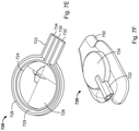
- FIGS. 36A-36B are side views of an illustrative variation of a sheath.
- FIGS. 37A-37B are side views of an illustrative variation of a sheath in patient anatomy.
- FIG. 38A is a perspective view
- FIGS. 38B-38C are cross-sectional side views, of an illustrative variation of a proximal end of a sheath.
- FIGS. 39A-39B are perspective views of illustrative variations of a proximal portion of a sheath.
- FIG. 1 is a cross-sectional view of the heart ( 100 ). Shown there is the left atrium ( 102 ) and the left ventricle ( 104 ). In between the left atrium ( 102 ) and the left ventricle ( 104 ) is the mitral valve (also known as the bicuspid valve), which is defined by a pair of mitral valve leaflets ( 106 ). The leaflets are connected to chordae tendinae ( 108 ) that are connected to papillary muscles ( 110 ). The papillary muscles join the ventricular wall ( 112 ). The left atrial appendage ( 114 ) is shown adjacent to, and is formed from, the wall of the left atrium ( 102 ).
- mitral valve also known as the bicuspid valve
- the leaflets are connected to chordae tendinae ( 108 ) that are connected to papillary muscles ( 110 ).
- the papillary muscles join the ventricular wall ( 112 ).
- the left atrial appendage ( 114 )
- the left atrial appendage ( 114 ) lies within the boundaries of the pericardium ( 116 ) and is in close proximity to the ventricular wall ( 112 ).
- the left atrial appendage typically has a tubular shape that approximates a cone, with a slight narrowing or neck in the plane of the orifice where it joins the left atrium ( 102 ).
- the left atrial appendage ( 114 ) is the most common location for thrombosis formation, which, in time, may dislodge and cause a devastating stroke.
- the left atrial appendage is frequently excluded from the left atrium in those patients undergoing procedures to treat atrial fibrillation, and is often removed or excluded at the time of other surgical procedures, such as mitral valve surgery, to reduce the risk of a future stroke.
- the devices and systems described here help ensure proper closure of the left atrial appendage at the neck or base of the left atrial appendage, along the anatomic ostial plane. In this way, exclusion of the entire left atrial appendage from systemic circulation may be facilitated.
- the closure devices may comprise an elongate body and a snare loop assembly at least partially extending from a distal end thereof.
- the snare loop assembly may form a loop and may comprise a snare, and a suture loop releasably coupled to the snare.
- the closure devices described here may further comprise a first lumen and a vacuum tube slidably positioned within the first lumen.
- the vacuum tube may comprise a lumen therethrough, which, in some variations, may house and/or be coupled to an imaging device.
- the vacuum tube may assist in both visualization and stabilization of target tissue.
- the vacuum tube may be used to 1) view and identify the internal structures of a patient's body as the closure device is advanced to a target tissue and positioned relative to the target tissue and/or 2) apply vacuum to the target tissue to draw the target tissue toward the closure device and/or maintain contact with the target tissue to facilitate advancement of the snare loop assembly around the target tissue. This functionality may be provided through epicardial access without the need for endocardial access.
- the vacuum tube may comprise an imaging device held with the vacuum tube and/or may be operably connected to an imaging device such that the images captured by the imaging device via the vacuum tube may be used to assist in advancing and/or positioning the vacuum tube relative to the target tissue (e.g., a camera positioned within or advanced through a vacuum tube lumen).
- the imaging device may further image the tissue drawn into the vacuum tube to confirm capture of the desired target tissue.
- tissue may be identified and/or mapped using a set of electrodes disposed on one or more of the internal and external surfaces of a closure device, a vacuum tube, and/or an imaging device.
- the electrical signal received by the electrodes in contact with tissue may be used to identify the tissue and/or the location of the device.
- the electrode data may be further combined with other visualization data (e.g., from a mapping system) to generate a visual map of the heart.
- other imaging methods for example, fluoroscopy, fluorescence (near-infrared fluorescence, laser-induced fluorescence) may be employed.
- the vacuum tube may assist with stabilization, the vacuum tube may provide suction to temporarily hold a portion of the target tissue against the suction tip of the vacuum tube and/or the closure device.
- the suction tip of the vacuum tube may be atraumatic so as to decrease the risk of damaging the tissue.
- the suction supplied by the vacuum tube may hold the target tissue in place relative to the closure device while a snare loop assembly is advanced or deployed around the left atrial appendage to temporarily or permanently close and/or ligate the target tissue.
- the visualization and/or stabilization of the target tissue provided by the vacuum tube may assist with effectively and efficiently advancing the closure device to the target tissue and positioning and holding the target tissue so that the snare loop assembly can be deployed and the suture loop can be placed at the desired location for tissue closure.
- the closure devices described here may be used to close and/or ligate a target tissue such as the left atrial appendage.
- the closure device In use in a left atrial appendage closure procedure, the closure device may be advanced, for example, percutaneously, toward a pericardial space.
- an imaging device disposed within the lumen of the vacuum tube may be used to assist in steering the closure device to the left atrial appendage. Once the closure device reaches the left atrial appendage, the imaging device may be used to visualize the left atrial appendage such that the vacuum tube may be advanced out of the elongate body and through the loop of the snare loop assembly towards a desired, visualized location on the left atrial appendage.
- the lumen of the vacuum tube may be used to apply a force (e.g., suction) to the left atrial appendage to pull the appendage toward the distal end of the vacuum tube lumen, thereby positioning the closure device for advancement of the snare loop assembly around the left atrial appendage.
- a force e.g., suction
- the snare loop assembly may be advanced along the vacuum tube, which may be used as a guide, distally toward and around the target tissue. The snare loop assembly may then be closed around the target tissue and the suture loop may be released from the snare loop assembly to temporarily or permanently close or ligate the target tissue.
- the closure devices described here may be suitable for advancement to the left atrial appendage using a minimally invasive approach, e.g., through a small incision above, beneath, or through the rib cage, through an incision in the costal cartilage or the xiphoid, or the like. Because the closure devices described here provide for visualization and stabilization of the left atrial appendage during closure, only a single point of access (e.g., incision or port) to the left atrial appendage may be required. Put another way, the closure devices described here may be used to close the left atrial appendage from the pericardial space without accessing the internal structures of the heart through the vasculature or otherwise.
- FIG. 2 depicts one illustrative variation of closure device ( 200 ) that may be used to close the left atrial appendage.
- the closure device ( 200 ) may comprise a snare loop assembly ( 202 ), an elongate body ( 204 ), and a handle ( 206 ).
- the handle ( 206 ) may be coupled to a proximal end of the elongate body ( 204 ) and may be used, among other things, to control and actuate the snare loop assembly ( 202 ), which may at least partially extend from a distal end of the elongate body ( 204 ).
- controls e.g., a slider, a button, knob, switch, or the like
- the handle ( 206 ) may move the snare loop assembly ( 202 ) between a closed configuration and an open deployed configuration.
- the snare loop assembly ( 202 ) and the elongate body ( 204 ) may form a continuous loop ( 208 ) (e.g., such that the snare loop assembly ( 202 ) and the elongate body ( 204 ) may fully encircle tissue placed in the loop ( 208 )).
- the size of the loop ( 208 ) may be reduced as some or all of the snare loop assembly ( 202 ) is withdrawn into the elongate body ( 204 ).
- the loop ( 208 ) may be provided entirely within the elongate body ( 204 ) or a substantial portion of the loop ( 208 ) may be provided within the elongate body ( 204 ) with a small portion of the loop ( 208 ) remaining outside of the elongate body ( 204 ). It should be noted that a vacuum tube is not shown in FIG. 2 for the sake of clarity and is described in more detail below.
- the snare loop assembly may be used to temporarily close and/or restrict one or more target tissues.
- the snare loop assembly comprises a closure element (e.g., a snare) and a suture loop releasably attached to the closure element.
- the snare loop assembly may comprise a retention member at least temporarily coupling the closure element and the suture loop.
- the snare may be at least partially modifiable to move the snare loop assembly between the open, closed and retracted configurations.
- a portion of the snare may be housed in the elongate body, and another portion of the snare may extend outside of the distal end of the elongate body to at least partially define the loop and aperture of the snare loop assembly.
- the snare loop assembly may be closed around tissue to temporarily or permanently close, ligate, or otherwise tighten tissue, and the suture loop may be tightened and released from the snare to hold or otherwise maintain the tissue in the closed configuration. Either before or after the suture loop is tightened, the snare loop assembly may be retracted into the elongate body to facilitate the removal of the closure device from confined body spaces. Once the suture loop is tightened around the left atrial appendage, the tissue suctioned from the suction tip of the vacuum tube may be released, which may allow for visual confirmation of the tissue closure by the imaging device.
- FIG. 3A shows a distal section of an illustrative variation of a closure device ( 300 ) comprising a snare loop assembly ( 302 ) and an elongate body ( 304 ) comprising a tip ( 306 ).
- the snare loop assembly ( 302 ) may comprise a snare ( 308 ), a suture loop ( 310 ), and a retention member ( 312 ), and may be disposed relative to the elongate body ( 304 ) such that at least a portion of the snare loop assembly ( 302 ) extends from the distal end of elongate body ( 304 ) (e.g., via tip ( 306 )).
- the snare loop assembly ( 302 ) is shown in FIG. 3A in an open configuration, and the portion of the snare loop assembly ( 302 ) extending out of the elongate body ( 304 ) may form a loop ( 314 ) having an aperture ( 316 ) therethrough.
- the loop ( 314 ) and the corresponding aperture ( 316 ) may be defined by one or more components of the snare loop assembly ( 302 ) (e.g., the snare) and the distal end of the elongate body ( 304 ), and may be suitable for encircling tissue such as the left atrial appendage.
- the snare ( 308 ) may be used to open and close the snare loop assembly ( 302 ).
- the retention member ( 312 ) may be configured to release the suture loop ( 310 ) from the snare loop assembly ( 302 ) upon application of a sufficient force to suture loop ( 310 ).
- the snare ( 308 ) may be moveable to change the configuration (e.g., shape, diameter, circumference) of the snare loop assembly ( 302 ).
- one end of the snare may be fixed relative to one or more portions of the closure device, while the other end may be coupled to a moveable portion of the handle such that it may be advanced or retracted through the elongate body. Movement of the free end of the snare may change the amount of the snare loop assembly that is disposed outside of the elongate body and around the vacuum tube (not shown), and thus may change the size (e.g., diameter, circumference, area) of the loop and the aperture defined thereby.
- advancement of the snare through the elongate body may increase the size of the loop and the aperture of the snare loop assembly, while retraction of the snare through the elongate body may decrease the size of the loop and the aperture of the snare loop assembly.
- the free end of the snare may be directly attached to one or more portions of the handle (e.g., a slider, button, knob, switch, or the like), or may be coupled to the handle via a rigid structure, for example a hypotube, a rod, or the like.
- the rigid structure may be coupled to and moved by the handle, which may advance or retract the free end of the snare and thus may open and close the snare loop assembly.
- the fixed end of the snare may be coupled to any suitable portion of the closure device, for example, any portion of the elongate body ( 304 ) including the tip ( 306 ) or the handle.
- the fixed end of the snare may be releasable, and in some instances retractable into a lumen of the elongate body, which may assist in releasing the target tissue from the aperture in the snare loop assembly after deployment of the suture loop. Utilizing a releasable or retractable snare may also assist with withdrawal of the closure device from body.
- the closure element may be made of any suitable material or combination of materials.
- the snare may be made from a shape-memory material, such as a shape-memory alloy (e.g., a nickel titanium alloy, etc.), or may be made from stainless steel, polyester, nylon, polyethylene, polypropylene, combinations thereof, or the like.
- the snare may be configured to take on a particular shape or configuration when the snare loop assembly is placed in an open configuration, but may still be at least partially withdrawn into the elongate body to place the snare loop assembly in a closed configuration.
- the snare may form a generally circular, teardrop-shaped, oval or ellipsoid, or triangular loop when the snare loop assembly is placed in an open configuration.
- the snare loop when the snare loop is in the closed configuration, it is at least partially withdrawn into the elongate body and tightened around the circumference of the vacuum tube that extends through the snare loop.
- the snare may be radiopaque and/or comprise radiopaque materials and/or markers.
- the snare loop assembly may be angled relative to the elongate body and/or the vacuum tube. Angling the snare relative to the elongate body and/or the vacuum tube may aid the snare in advancement over a vacuum tube and capturing tissue, as angling may better position the snare relative to tissue.
- the plane of snare loop assembly ( 302 ) is approximately perpendicular to the distal end of the elongate body ( 304 ), however, the plane of the snare loop assembly ( 302 ) may be varied over a wide range of angles (a), as depicted in FIGS. 3B-3D .
- the angle (a) may be preset, while in other variations, the angle (a) is adjustable within a predetermined range.
- the angle (a) formed between the plane of the snare loop assembly ( 302 ) and the distal end of the elongate body ( 304 ) may be between about 5 degrees and about 85 degrees ( FIG. 3C ), may be between about 5 degrees and about 45 degrees, may be about 90 degrees ( FIG. 3B ), or may be between about 95 degrees and less than 180 degrees ( FIG. 3D ). It should be noted that the angle (a) may be nearly 180 degrees so long as the vacuum tube (not shown) is configured to extend through an aperture ( 316 ) of the snare loop assembly ( 302 ).
- the snare loop assemblies described here may also comprise a suture loop for maintaining tissue in a closed manner.
- the suture loop may be releasably attached to the snare, for example, via a retention member, as will be described in more detail below.
- the suture loop may comprise a suture knot, but need not.
- This suture knot may be any suitable knot, including, but not limited to, a slip knot (e.g., a one-way slip knot) or a Meltzer knot. In some variations, at least a portion of the knot may be held within the tip of the elongate body.
- the suture knot at least partially extends from the tip of the elongate body or may be positioned outside of the tip and may be temporarily held in fixed relation to the elongate body.
- the suture loop may comprise a loop portion, a suture knot, and a tail extending from the suture knot. The suture tail may be pulled through the suture knot to reduce the diameter of the loop portion.
- the suture loop may be advanced or withdrawn through the slip knot to change the size of the suture loop.
- the suture knot may not move while the size of the suture loop is changed. This may help prevent the closure device from damaging tissue.
- the suture loop may comprise a unidirectional locking structure.
- the unidirectional locking structure may be any structure capable of being advanced along the suture in one direction but resisting movement in a second direction.
- the locking structure may be advanced over a portion of the suture loop to help lock a suture knot in place.
- the locking structure may be advanced via one of the closure devices described here, or it may be advanced by a separate device after the suture loop has been released from the closure device.
- the suture loop may be made from any suitable material useful in tissue exclusion or closure.
- it may be made of a biodegradable material (e.g., polylactic acid, polyglycolic acid, polylactic-co-glycolic acid, etc.), or it may be made of a non-biodegradable material (e.g., metal, steel, polyester, nylon, propylene, silk, combinations thereof, etc.).
- a biodegradable material e.g., polylactic acid, polyglycolic acid, polylactic-co-glycolic acid, etc.
- non-biodegradable material e.g., metal, steel, polyester, nylon, propylene, silk, combinations thereof, etc.
- the suture loop When the suture loop is tightened to close tissue, it may be possible for tissue to be pulled into the suture knot of the suture loop. If too much tissue is pulled into the suture knot, the suture knot may clog or jam in a way that prevents the suture loop from being further tightened.
- the suture loop may comprise one or more pledgets or tube sections to help shield a portion of the suture knot.
- a distal tip of an elongate body may comprise a suture loop severing assembly (e.g., a suture cutter) configured to separate a tightened suture loop from a closure device.
- a suture loop severing assembly e.g., a suture cutter
- a portion of the suture disposed within the distal tip may be cut using a blade disposed in the distal tip to separate the suture loop from the closure device.
- the closure devices described herein may deliver, tighten, and release a suture loop from the closure device (e.g., cut or otherwise sever the suture such that the suture loop may remain within the body after removal of the closure device) without additional devices.
- FIG. 28A-28B depict a suture loop severing assembly (e.g., a suture cutter) ( 2810 ) disposed in a distal end, for example, in the distal tip ( 2804 ), of a closure device ( 2800 ).
- the closure device ( 2800 ) may comprise an elongate body ( 2802 ) coupled to the distal tip ( 2804 ).
- a suture ( 2806 ) may extend through respective lumens of the distal tip ( 2804 ) and elongate body ( 2802 ).
- the suture loop severing assembly ( 2810 ) may be disposed within a proximal portion of the distal tip ( 2804 ) and may comprise a severing assembly housing ( 2812 ).
- the severing assembly housing ( 2812 ) may define a first severing assembly lumen ( 2818 ) and a second severing assembly lumen ( 2820 ) that may be parallel to one another. At least a portion of a suture cutter ( 2814 ) (e.g., the edge of a blade) may be disposed within the second severing assembly lumen ( 2820 ). For example, the suture cutter ( 2814 ) may be mounted on a top surface of the severing assembly housing ( 2812 ) at an angle relative to a longitudinal axis of the distal tip ( 2804 ) and extend into the second severing assembly lumen ( 2820 ).
- the suture cutter ( 2814 ) may have a length between about 0.5 mm and about 1.3 mm.
- the suture ( 2806 ) may extend through the first severing assembly lumen ( 2818 ).
- a control wire ( 2816 ) may extend through the second severing assembly lumen ( 2820 ) and be attached or otherwise coupled to the suture ( 2806 ) within the distal tip ( 2804 ).
- the control wire ( 2816 ) may couple (e.g., loosely) to the suture ( 2806 ) distal to the suture cutter ( 2814 ) and proximal to the suture loop and the suture knot (not depicted).
- the control wire ( 2816 ) may extend through a control wire lumen in the elongate body ( 2802 ) and couple to an actuator in a handle (not shown).
- heat or RF energy may be used to sever the suture instead of a blade.
- the suture loop severing assembly ( 2810 ) may comprise an electrode or other device configured to generate heat or radiofrequency energy, which may be used to sever the suture ( 2806 ).
- the suture loop severing assembly ( 2810 ) may be configured to cut the suture ( 2806 ) at a predetermined location (e.g., just distal to the attachment point with the control wire ( 2816 ) and proximal to the suture loop and suture knot) upon retraction of the control wire ( 2816 ) in a proximal direction.
- a distal end of the control wire ( 2816 ) e.g., a pull wire
- the suture cutter ( 2814 ) disposed within the second severing assembly lumen ( 2820 ) may thus contact and cut the portion of the suture ( 2806 ) drawn into the second severing assembly lumen ( 2820 ).
- a retraction force e.g., a pulling force
- the suture ( 2806 ) will not come into contact with the suture cutter ( 2814 ).
- the retention member may be any suitable member, such as dual-lumen tubing.
- one lumen may have a slit, perforation, or other opening along its length, which may allow the suture to pass therethrough when it is ready to be deployed.
- the slit need not extend or be continuous along the entire length of the retention member.
- the slit may have prongs or arms along its length to help capture and retain the suture in the retention member.
- the slit may be covered at spaced-apart locations with a biodegradable polymer, which may temporarily tack or hold down the suture.
- the retention member may not comprise a slit, and may instead comprise some other type of retention mechanism, such as the prongs or tacks described just above.
- the suture loop may be released upon removing or withdrawing the retention member.
- the closure devices described here generally comprise an elongate body.
- the elongate body may house various components or portions thereof, for example, a portion of the snare, the suture loop, the retention member, imaging device, and the vacuum tube, and may provide a conduit to connect these elements to the handle.
- the snare and the vacuum tube may be slidable within the elongate body such that the snare and the vacuum tube may be advanced and retracted relative to the elongate body.
- At least a portion of the elongate body may be flexible and/or steerable (e.g., using pull wires or any other suitable steering mechanism), which may help facilitate navigation of the elongate body through the body to a target tissue.
- flexible and/or steerable e.g., using pull wires or any other suitable steering mechanism
- Utilizing an elongate body that is flexible and/or steerable may be especially useful in instances in which it is difficult to access the target tissue during a procedure because, for example, it may be underneath or covered by other anatomical structures.
- the elongate body may comprise various sections or portions with different characteristics, for example, different diameters, cross-sectional shapes, stiffnesses, materials, or the like, which may increase the steerability and maneuverability of the closure device.
- the elongate body may be braided, non-braided, tapered, non-tapered, or some combination thereof.
- at least a portion of the elongate body may be shapeable, meaning that the elongate body may be manipulated (e.g., bent) and may retain the manipulated shape until a user or other applied force (e.g., from tissue within the body) further modifies it.
- the elongate body ( 402 ) may comprise a tip ( 406 ) at the distal end thereof.
- the tip ( 406 ) of the elongate body ( 402 ) may be formed separately from the elongate body ( 402 ), and may be attached to the elongate body ( 402 ) during assembly of the closure device using any suitable means (e.g., welded, using adhesive, using connectors).
- the tip ( 406 ) may be integral with the elongate body ( 402 ).
- the tip ( 406 ) may have the same number of lumens as the elongate body ( 402 ), but need not.
- the tip ( 406 ) may divide one or more lumens of the elongate ( 402 ) body into two or more sub-lumens. In other variations, the tip ( 406 ) may alter the size or shape of one or more lumens of the elongate body ( 402 ).
- the elongate body may comprise any suitable cross-sectional shape, for example, circular, oval, D-shaped, triangular, or the like.
- the cross-sectional shape of the elongate body may vary along its length.
- FIG. 4D provides a perspective view of a distal end of the elongate body ( 402 ) having different portions.
- the elongate body may comprise a proximal portion with a first cross-sectional shape (e.g., circular) and a distal portion with a second cross-sectional shape (e.g., D-shaped).
- the elongate body may comprise any suitable number of portions, e.g., two, three, or four portions, and the length of each portion may be the same as or different from the other portions.
- the elongate body may further comprise one or more transitions connecting the portions of the elongate body comprising different diameters or different cross-sectional shapes.
- the elongate body and vacuum tube may have different shapes, sizes, components, portions, and other characteristics, as described in more detail below.
- the closure devices described here may include any of the features or elements, for example, any of the elongate body configurations, described in U.S. patent application Ser. No. 15/080,410, entitled “Devices and Methods for Left Atrial Appendage Closure” and filed on Mar.
- the diameters and cross-sectional shapes of the elongate body may be different along each of the cross-sectional lines FF, GG, and HH, as shown in corresponding FIGS. 4F-4H and discussed in more detail below.
- the elongate body described herein may comprise any suitable length and outer diameter, and the length and diameter of the elongate body may vary depending on the type of procedure being performed. For example, in some instances it may be desirable to limit the outer diameter of the elongate body such that it may fit through 18-French percutaneous tubing. In some variations, the outer diameter of the elongate body may also vary along its length.
- the elongate body may be made of any suitable material, for example, one or more polymers (e.g., polyether block amide, polyethylene, silicone, polyvinyl chloride, latex, polyurethane, PTFE, nylon, etc.).
- the closure devices described here may comprise a vacuum tube.
- the vacuum tube may be configured to be slidably positioned relative to an elongate body such that the vacuum tube may advance and retract with respect to the elongate body.
- the vacuum tube may be configured to fit within a lumen of the elongate body or to slide adjacent the elongate body.
- the vacuum tube may assist with direct visualization of tissue structures (e.g., for appropriate placement of the vacuum tube relative to the tissue in order to guide a closure element), identification and/or mapping of tissue structures, and stabilization of the closure device relative to the target tissue for advancement of the closure element around the tissue.
- an imaging device may be disposed within a lumen of the vacuum tube and vacuum may be applied to the tissue in contact with the vacuum tube to temporarily hold the left atrial appendage.
- the closure device guided to the left atrial appendage and the closure element can be properly placed to effectuate tissue closure without a separate device, thereby improving safety and reducing complexity of the closure procedure.
- FIG. 4A is a perspective view of an illustrative variation of a closure device ( 400 ) comprising an elongate body ( 402 ), a snare loop assembly ( 404 ), a vacuum tube ( 430 ), and a handle ( 450 ).
- the handle ( 450 ) may be coupled to the proximal ends of the elongate body ( 402 ) and the vacuum tube ( 430 ), and the vacuum tube ( 430 ) may be slidably positioned within a lumen of the elongate body ( 402 ) such that the handle ( 450 ) may be used to advance and retract the vacuum tube ( 430 ) relative to the elongate body ( 402 ).
- the handle ( 450 ) may also be used to move the snare loop assembly ( 404 ) between open and closed configurations, control the vacuum pressure applied to the target tissue through the vacuum tube ( 430 ), control operation and/or advancement of an imaging device (not depicted) positioned within the vacuum tube, and/or release the suture loop from the snare loop assembly.
- the vacuum tube ( 430 ) may comprise a proximal portion (not shown), an intermediate portion ( 442 ), a distal end ( 432 ), and a lumen therethrough ( 440 ).
- the lumen ( 440 ) may have any configuration sufficient to provide negative pressure at the distal end ( 432 ) when a proximal end of the lumen ( 440 ) is coupled to a vacuum source.
- a diameter of the distal end ( 432 ) may be greater than a diameter of an intermediate portion ( 442 ) of the vacuum tube ( 430 ) (shown in FIGS.
- the intermediate portion ( 442 ) and proximal portion of the vacuum tube ( 430 ) may be sized to fit within a lumen of the elongate body ( 402 ) and hold within the lumen ( 440 ) one or more power and data conductors coupled to an imaging and/or sensing device as discussed in further detail below.
- the intermediate portion ( 442 ) of the vacuum tube ( 430 ) may further be flexible to steer the distal end ( 432 ) of the vacuum tube ( 430 ) towards a desired location.
- the distal end ( 432 ) may be sized to accept tissue when negative pressure is applied and may be atraumatic such that it does not lacerate, puncture, or otherwise damage the tissue when releasably coupled thereto.
- the distal end ( 432 ) may comprise a cone, cup-shaped, or otherwise concave configuration.
- the distal end ( 432 ) may be configured to releasably couple to the tissue surface via suction when pressed against the tissue (e.g., be a suction cup).
- the distal end ( 432 ) may remain relatively rigid to aid in holding a target tissue. At least a portion of the proximal end of the vacuum tube ( 430 ) may be slidably disposed within the lumen of the elongate body ( 402 ).
- the distal end ( 432 ) of the vacuum tube ( 430 ) may comprise an atraumatic grasping element to physically engage and hold tissue adjacent to the vacuum tube ( 430 ) without damaging the tissue.
- the distal end ( 432 ) of the vacuum tube ( 430 ) may be configured to grasp the tissue such that a seal is formed between the distal end ( 432 ) and the tissue.
- the proximal end of the vacuum tube ( 430 ) may be coupled to a vacuum source and the distal end ( 432 ) may be sized and shaped such that a vacuum seal is temporarily formed when the distal end ( 432 ) of the vacuum tube ( 430 ) contacts tissue and the vacuum source is activated.
- the distal end of the vacuum tube may comprise a shape and size configured to form a vacuum seal between the distal end of the vacuum tube and the tissue with predetermined attachment strength.
- the distal end of the vacuum tube may have an opening height substantially equal to a height of left atrial appendage tissue to fill the lumen of the distal end of the vacuum tube such that a vacuum seal may be formed.
- the strength of a vacuum force holding the distal end to heart tissue may be proportional to the area of the distal end's opening, assuming that the opening is substantially occluded by tissue to form a vacuum seal.
- the suction tip of the vacuum tube may be configured to grasp and/or surround a left atrial appendage.
- the suction tip of the vacuum tube may comprise one or more shapes and/or soft enclosures (e.g., bags, balloons) to surround at least a portion of the left atrial appendage.
- an inflatable bag of the suction tip may be inflated to push the left atrial appendage against other heart tissue to hold the left atrial appendage in place therebetween.
- FIG. 19 is a perspective view of another variation of a vacuum tube ( 1900 ) comprising a distal suction tip ( 1902 ), a vacuum tube ( 1904 ), a Y-arm ( 1906 ), and an imaging device ( 1912 ) (e.g., camera, endoscope, fiberscope, external light source and imaging sensor, ultrasonic catheter, or the like).
- the imaging device ( 1912 ) may be fixed relative to the vacuum tube or may be slidably positioned within a lumen of the vacuum tube ( 1904 ).
- a proximal end of the Y-arm ( 1906 ) may be coupled to a first seal (e.g., Tuohy-Borst type seal) that may be configured to prevent vacuum leaks out of a proximal end of the vacuum tube ( 1900 ).
- the seal may allow an imaging device (e.g., a cable coupled to a distal end of the imaging device) to be disposed in the vacuum tube lumen, which may be used to communicate negative pressure to the suction tip.
- a second seal may be disposed proximal to the first seal to further improve a vacuum seal.
- a handle may be coupled to the proximal end of the elongate body ( 1904 ).
- the handle may also be used to control one or more of the vacuum pressure applied to the target tissue through the elongate body ( 1904 ) and operation and/or advancement of the imaging device ( 1912 ) positioned within the elongate body ( 1904 ).
- the Y-arm ( 1906 ) may be used to couple a proximal end of the elongate body ( 1904 ) to a vacuum source (e.g., electronic or mechanical vacuum pump) as described in more detail herein.
- a proximal end of the imaging device ( 1912 ) may comprise an imaging device connector ( 1914 ) that may be configured to couple the imaging device ( 1912 ) to a device that may process and/or display images for use during a procedure (e.g., image processor and memory, user console, display, remote network, and/or the like).
- a device that may process and/or display images for use during a procedure (e.g., image processor and memory, user console, display, remote network, and/or the like).
- FIG. 20 is a perspective view of a variation of a suction tip ( 2004 ) of a vacuum tube ( 2000 ).
- the vacuum tube ( 2000 ) may comprise an elongate body ( 2002 ) coupled to the suction tip ( 2004 ).
- the suction tip ( 2004 ) may be coupled to a distal end of the elongate body ( 2002 ).
- the suction tip ( 2004 ) may be formed separately from the elongate body ( 2002 ), and may be attached to the elongate body ( 2002 ) during assembly of the vacuum tube ( 2000 ) using any suitable means (e.g., welded, using adhesive, using connectors).
- the suction tip ( 2004 ) may be integral with the elongate body ( 2002 ).
- An imaging device ( 2008 ) may be slidably positioned or fixed within a lumen of the suction tip ( 2004 ) and elongate body ( 2002 ) as described herein.
- the suction tip ( 2004 ) may comprise an obround cup ( 2006 ).
- the obround cup ( 2006 ) may be configured to couple with tissue (not shown) by providing a vacuum seal around a circumference of an opening ( 2010 ) when a vacuum suction force is applied.
- a surface area of the suction tip ( 2004 ) may be increased by increasing a length of the opening ( 2010 ) relative to its width.
- the obround cup ( 2006 ) may comprise a height about equal to a thickness of the left atrial appendage or of target tissue to be suctioned.
- an outer width of the obround cup ( 2006 ) may be less than about 20 French and an internal surface height of the obround cup ( 2006 ) may be between about 2 mm and about 3 mm.
- An obround cup ( 2006 ) within these dimensions may contact tissue along an entire circumference of the opening ( 2010 ) and thus provide increased vacuum holding force relative to an opening of a suction tip ( 2004 ) of an elongate body ( 2002 ) having a smaller surface area.
- the obround cup ( 2006 ) may have a diameter of up to about 20 French.
- the obround distal tip ( 2006 ) may comprise a rigid polymer (e.g., stainless steel, plastic such as ultem, ABS, polycarbonate, a combination thereof, or the like) while one or more portions of the vacuum tube ( 2002 ) may comprise a more flexible material (e.g., reinforced pebax, polyimide, urethane, a combination thereof, or the like). Additionally or alternatively, in some variations, the vacuum tube ( 2002 ) may comprise braided polyimide and/or stainless steel wire braid having a relatively stiff wall configured to maintain its shape under negative pressure.
- a rigid polymer e.g., stainless steel, plastic such as ultem, ABS, polycarbonate, a combination thereof, or the like
- the vacuum tube ( 2002 ) may comprise braided polyimide and/or stainless steel wire braid having a relatively stiff wall configured to maintain its shape under negative pressure.
- a suction tip of a vacuum tube may be configured to transition between a collapsed configuration and an expanded configuration, which may aid in advancement of the vacuum tube through a lumen and may increase a cross-sectional area of tissue that may be suctioned.
- a cross-sectional area of the suction tip may be minimized to allow advancement of the vacuum tube through a sheath (e.g., cannula) for delivery of the vacuum tube into a pericardial cavity.
- a sheath e.g., cannula
- the suction tip may transition to the expanded configuration having a larger diameter or transverse dimension than a lumen of the sheath.
- the expanded vacuum tube may be configured to draw a larger volume of tissue into a lumen of the suction tip.
- the suction tip may later transition back into the collapsed configuration for retraction and withdrawal from the patient.
- the suction tip may transition between collapsed or delivery/withdraw and expanded/deployed configurations using any suitable mechanism, for example, a fluid-based mechanism or a mechanical mechanism.
- the suction tip may be self-expanding (e.g., naturally biased towards an expanded configuration).
- the suction tip may comprise a shape memory material (e.g., a nickel titanium alloy) or other material that is biased toward an expanded configuration that may be advanced through and constrained within a lumen of an elongate body or sheath.
- the suction tip When advanced out of the lumen, the suction tip may naturally transition to the expanded configuration.
- One or more portions (e.g., a proximal portion) of the suction tip may be angled in the expanded configuration such that the suction tip may be retracted back into the lumen and become constrained again (e.g., re-form a collapsed configuration).
- FIGS. 25A-25B depict a variation of a vacuum tube that may transition between a collapsed configuration and an expanded configuration using fluid.
- the distal end (e.g., suction tip, vacuum cup) of the vacuum tube depicted in FIGS. 25A-25B may be filled with a fluid to rigidize the suction tip and allow tissue to be suctioned into a cavity formed in the suction tip.
- a suction tip of a vacuum tube may be advanced in a first configuration (e.g., collapsed, compact, rolled-up, compressed, delivery) and then expanded into a second configuration (e.g., rigid, expanded, inflated, deployed) once a target tissue is reached, where the suction tip in the second configuration may be configured to physically engage tissue adjacent to the suction tip by applying vacuum suction force to the tissue.
- a vacuum tube ( 2500 ) may comprise an elongate body ( 2502 ) comprising a first lumen ( 2504 ) and a second lumen ( 2506 ).
- the second lumen ( 2506 ) may be disposed within the first lumen ( 2504 ) such that the second lumen ( 2506 ) has a smaller outer diameter than the first lumen ( 2504 ). That is, the second lumen ( 2506 ) may be concentric with or otherwise configured to nest within the first lumen ( 2504 ). In some variations, the second lumen ( 2506 ) may have internal diameter between about 2 mm and about 3 mm.
- a suction tip ( 2510 ) of the vacuum tube ( 2500 ) is shown in FIGS. 25A-25B in the second configuration, in which it may have a shape that is generally conical (e.g., funnel, cup), cylindrical, obround, polygonal, and/or the like.
- the suction tip ( 2510 ) may comprise an opening ( 2514 ) having a distal diameter greater than that of the second lumen ( 2506 ).
- the first and second lumens need not be concentric with each other.
- the second lumen may comprise a set of two crescent-shaped lumens disposed around a central first lumen.
- the crescent-shaped lumens may be on opposite sides of the first lumen (e.g., on top and bottom, on left and right).
- the suction tip ( 2510 ) may comprise a soft enclosure (e.g., bag, balloon) that comprises a third lumen ( 2512 ) (e.g., distal lumen).
- a distal end of the first lumen ( 2504 ) may be coupled to and in fluid communication with the third lumen ( 2512 ) such that the third lumen ( 2512 ) may be inflated using fluid directed through the first lumen ( 2504 ).
- a distal end of the second lumen ( 2506 ) may be coupled to the opening ( 2514 ) of the suction tip ( 2510 ).
- a proximal end of the elongate body ( 2502 ) may be coupled to a Y-arm (not shown) and configured to slidably position the second lumen ( 2506 ) relative to the first lumen ( 2504 ).
- the position of the second lumen ( 2506 ) may be fixed relative to the first lumen ( 2504 ) using, for example, a proximal portion ( 2520 ) of the suction tip ( 2510 ).
- the first lumen ( 2504 ) and second lumen ( 2506 ) may be fixed relative to each other at a handle. For example, in the first configuration, the second lumen ( 2506 ) may be withdrawn from a distal end of the elongate body ( 2502 ).
- the suction tip may transition from the first configuration to the second configuration using fluid.
- the first lumen ( 2504 ) and the third lumen ( 2512 ) in the first configuration may be empty of fluid (e.g., gas, liquid).
- the suction tip ( 2510 ) may comprise a compressed or low-profile shape having a smaller volume of space and may thus easily advance through a sheath and/or elongate body (not shown).
- the suction tip ( 2510 ) in the first configuration may compress such that a distal portion of the suction tip ( 2510 ) may fold over on itself or otherwise form lower profile such that it may fit within a lumen of a smaller sheath.
- the suction tip ( 2510 ) may be in a collapsible state.
- the second lumen ( 2506 ) may be slidably advanced within the first lumen ( 2504 ) to couple to the suction tip ( 2510 ) (e.g., such that the second lumen ( 2506 ) is flush with a proximal end of the suction tip).
- the first lumen ( 2504 ) may be coupled to a fluid source (e.g., a syringe filled with fluid) and may then be filled with a fluid (e.g., saline, contrast agent, CO 2 , and combinations thereof) that flows into and fills the third lumen ( 2512 ) of the suction tip ( 2510 ) with the fluid, thereby transitioning the suction tip ( 2510 ) from the first delivery configuration to the second deployed configuration, in which it may be rigid, expanded, and/or inflated.
- Fluid flow through the first lumen ( 2504 ) and into the third lumen ( 2512 ) is depicted by a solid arrow in FIG. 25A .
- Small air bubbles may be present in one or more of the first lumen ( 2504 ) and third lumen ( 2512 ) without negative consequence to the rigidity of the vacuum tube ( 2500 ).
- the second lumen ( 2506 ) and opening ( 2514 ) may form a working channel through which suction may be applied and/or a device (e.g., imaging device) may be advanced.
- FIG. 25A depicts a vacuum suction force being applied within the opening ( 2514 ) and second lumen ( 2506 ).
- the first lumen ( 2504 ) and third lumen ( 2512 ) in the second configuration may have a pressure (e.g., fluid pressure) at least equal to a suction force applied through the second lumen ( 2506 ) and opening ( 2514 ) of the suction tip ( 2510 ).
- the suction tip ( 2510 ) may be configured to withstand a pressure of up to about 400 psi (or 27 atm) before failure (e.g., before the soft enclosure leaks and/or bursts).
- the suction tip may be made of any suitable material or combination of materials.
- the suction tip may comprise a balloon made from nylon, polyethylene terephthalate, combinations thereof, or the like.
- the suction tip may be configured to take on a particular shape or configuration when the suction tip is inflated in the second configuration.
- the suction tip may form a shape that is generally conical, diamond, spherical, pyramidal, or the like, when in the second configuration.
- the suction tip may be translucent, opaque, and/or colored (e.g., as a visual marker for an imaging device).
- one or more portions of the suction tip and/or elongate body may be radiopaque and/or comprise radiopaque material and/or markers.
- FIGS. 33A-33D depict variations of a suction tip of a vacuum tube that may be mechanically operated to transition between collapsed and expanded configurations.
- FIG. 33A illustrates a suction tip ( 3300 ) coupled to a vacuum tube ( 3302 ).
- the suction tip ( 3300 ) may comprise a distal hub ( 3304 ) (hidden in FIG. 33A under the cover ( 3306 )) coupled to a frame ( 3310 ) covered by a cover ( 3306 ).
- the distal hub ( 3304 ) and/or cover ( 3306 ) may be coupled to the vacuum tube ( 3302 ) via a seal ( 3308 ).
- FIG. 33B depicts the suction tip with the cover ( 3306 ) removed for clarity.
- the hub ( 3304 ) may be fixed to the outside diameter of the vacuum tube ( 3302 ).
- the hub ( 3304 ) may comprise a first hub lumen ( 3305 ) operatively coupled to a lumen of the vacuum tube ( 3302 ).
- the frame ( 3310 ) may comprise a set of first support members ( 3312 ) (e.g., a pair of longitudinal struts) and a set of second support members ( 3314 ) (e.g., a pair of longitudinal struts).
- the support members ( 3312 , 3314 ) may be parallel to a longitudinal axis of the suction tip ( 3300 ).
- the second support members ( 3314 ) may comprise one or more curved portions ( 3315 ) along a length of the suction tip.
- the first support members ( 3312 ) may advance and retract along the longitudinal axis of the suction tip ( 3300 ) while the second support members ( 3314 ) may move laterally relative to the longitudinal axis of the suction tip ( 3300 ).
- a set of support connectors ( 3316 ) may be coupled between adjacent first and second support members ( 3312 , 3314 ).
- the support connectors may comprise elongate metal or hard plastic struts that are angled relative to the longitudinal axis.
- One or more control wires ( 3320 ) may extend through (e.g., positioned within a lumen or corresponding lumens of) the vacuum tube ( 3302 ) and distal hub ( 3304 ) and be coupled to the first support members ( 3312 ) of the frame ( 3310 ).
- the control wires ( 3320 ) may be operated independently. As shown in FIG. 33B , the distal ends of the control wires ( 3320 ) may be coupled to the proximal ends of the first support members ( 3312 ).
- Advancement and retraction of the control wires ( 3320 ) may change a configuration of the frame ( 3310 ) and thus the suction tip by moving the first support members ( 3312 ) longitudinally and the second support members ( 3314 ) laterally, as described in more detail herein.
- the geometry of the frame components are such that the second support members ( 3314 ) remain parallel to the first support members ( 3312 ) as the second support members ( 3314 ) move laterally.
- each of the second support members ( 3314 ) may be coupled to a ramp ( 3318 ) (e.g., a triangular or wedge shaped plate) configured to slide along a distal face of the hub ( 3304 ).
- a ramp ( 3318 ) e.g., a triangular or wedge shaped plate
- each ramp ( 3318 ) may force the second support members ( 3314 ) to displace laterally relative to the longitudinal axis of the suction tip ( 3300 ).
- the support connectors ( 3316 ) may flex away from the first support members ( 3312 ) and store spring energy.
- the control wires ( 3320 ) may be released, thus allowing the second support members ( 3314 ) to relax and come together, thereby drawing the second support members ( 3314 ) back into the collapsed configuration.
- FIG. 33C is a cross-sectional perspective view of the suction tip ( 3300 ) and vacuum tube ( 3302 ) without the cover ( 3306 ).
- the vacuum tube ( 3302 ) may comprise a plurality of lumens including a first vacuum tube lumen ( 3330 ) and a second vacuum tube lumen ( 3332 ).
- an imaging device e.g., camera, endoscope, fiberscope, ultrasonic catheter, or the like
- the control wire ( 3320 ) may be disposed in the second vacuum tube lumen ( 3332 ).
- the distal hub ( 3304 ) may comprise a first hub lumen ( 3305 ) and a second hub lumen ( 3307 ).
- the first hub lumen ( 3305 ) may be operatively coupled to the first vacuum tube lumen ( 3330 ) and the second hub lumen ( 3307 ) may be operatively coupled to the second vacuum tube lumen ( 3307 ).
- the control wire ( 3320 ) may be slideable within the second hub lumen ( 3307 ).
- One or more control wires ( 3320 ) may extend to a proximal end of the vacuum tube ( 3302 ) and be coupled to an actuator (not shown) (e.g., an actuator disposed in a handle).
- FIG. 33D is a front view of the suction tip ( 3300 ) of a vacuum tube ( 3302 ) in a collapsed configuration sized to slide within a lumen of a sheath ( 3350 ).
- FIGS. 34A-34C illustrate the suction tip ( 3402 ) of the vacuum tube ( 3400 ) (with and without a cover) advanced out of a sheath ( 3404 ) in various configuration states.
- FIG. 34A depicts the suction tip ( 3402 ) in a collapsed configuration, in which it is configured (e.g., sized) to slide within a lumen of the sheath ( 3404 ).
- a control wire of the suction tip may be in the fully distal position.
- suction tip ( 3402 ) is partially expanded into an intermediate configuration.
- a width of the suction tip ( 3402 ) may be larger than a diameter of the sheath ( 3404 ) and the control wire may be in the partially retracted position.
- the suction tip ( 3402 ) is in the fully expanded configuration.
- the control wire is in the fully proximal position and the suction tip ( 3402 ) is in the fully expanded configuration.
- the fully expanded configuration has the largest cross-sectional area (length and width) relative to the collapsed and intermediate configurations, thereby providing a larger surface area for tissue contact.
- a vacuum suction force may be applied to the vacuum tube ( 3400 ) and suction tip ( 3402 ) in any of the aforementioned configurations, however, it may be most effective in the fully expanded configuration in which the vacuum tip is configured to contact the largest surface are of tissue relative to the other configurations.
- the suction tip may comprise any suitable length, and the length of the suction tip may vary depending on the type of procedure being performed. In some variations, the suction tip may have a length between about 10 mm and about 25 mm. In some variations, an expanded to collapsed ratio of a width of the suction tip may be about 2 to 1 (i.e., the width of the suction tip may be about twice as large in the expanded configuration than in the collapsed configuration).
- the cover of the suction tip may be made of any suitable material, for example, one or more compliant, flexible materials including, but not limited to, low-durometer silicone, thermoplastic elastomers, a combination thereof, or the like.
- the frame of the suction tip may be made of any suitable material, for example, one or more rigid materials including, but not limited to, stainless steel, a nickel titanium alloy, a rigid polymer (e.g., polyimide, polyetherimide), a combination thereof, or the like.
- rigid materials including, but not limited to, stainless steel, a nickel titanium alloy, a rigid polymer (e.g., polyimide, polyetherimide), a combination thereof, or the like.
- FIG. 7A is a perspective view of a variation of a suction tip ( 700 ) of a vacuum tube and FIG. 7B depicts the suction tip ( 700 ) coupled to tissue ( 750 ).
- the suction tip ( 700 ) may comprise an obround cup ( 704 ) and a connector ( 702 ) configured to couple to a vacuum tube (not shown).
- the obround cup ( 704 ) may be configured to couple with tissue ( 750 ) by providing a vacuum seal around a circumference of an opening ( 705 ).
- a surface area of the suction tip ( 700 ) of a vacuum tube may be increased by increasing a length of an opening relative to its width.
- the obround cup ( 704 ) may have a length-to-width ratio of between about 4:1 and about 1.5:1. In one variation, the obround cup ( 704 ) may have a length-to-width ratio of about 3:1. An obround cup ( 704 ) within these ratios may contact tissue ( 750 ) along an entire circumference of the opening ( 705 ) and thus provide increased vacuum holding force relative to an opening of a suction tip of a vacuum tube having a smaller surface area.
- a connector opening ( 703 ) may be perpendicular to an obround opening ( 705 ) such that suction may be provided in a direction perpendicular to a lumen of the connector ( 702 ).
- This configuration may bring the closure device close to tissue ( 750 ), which may decrease the distance that the snare loop assembly needs to travel to be advanced over the tissue ( 750 ).
- a suction tip ( 700 ) configured to couple to a lengthwise side of tissue ( 750 ), such as a lengthwise side of the left atrial appendage shown in FIG. 7B , may bring the closure device closer to the left atrial appendage than if coupled to an apex ( 752 ) of the left atrial appendage.
- the obround suction tip ( 700 ) may comprise a rigid polymer having a height between about 0.20 cm and about 1.0 cm, a width between about 0.20 cm and about 1.50 cm, and a length between about 1.0 cm and about 3.0 cm.
- the obround suction tip ( 700 ) may have a length-to-width ratio of between about 15:1 and about 1.5:1.
- the obround suction tip ( 700 ) may have a length-to-width ratio of about 5:1.
- the obround suction tip ( 700 ) may have a length-to-width ratio of about 2:1.
- the obround suction tip ( 700 ) may have a length-to-width ratio of about 2.5:1. In some variations, the obround suction tip ( 700 ) may comprise a height of about 0.60 cm, a width of about 0.80 cm, and a length of about 2.0 cm.
- a suction tip of the vacuum tube may physically engage tissue adjacent to the vacuum tube through physically grasping tissue and the optional application of a vacuum suction force to the tissue.
- FIG. 7C is a perspective view of a suction tip ( 710 ) of a vacuum tube and FIG. 7D depicts the suction tip ( 710 ) of the vacuum tube coupled to tissue ( 750 ).
- the suction tip ( 710 ) of the vacuum tube ( 700 ) is in the form of a gripper comprising a U-shaped portion ( 714 ) and a connector ( 712 ) configured to be coupled to a vacuum tube (not shown).
- the U-shaped portion ( 714 ) may comprise a first arm ( 718 ), a second arm ( 720 ), and a plurality of protrusions ( 716 ) disposed along an interior surface of the U-shaped portion ( 714 ).
- the first and second arms ( 718 , 720 ) and protrusions ( 716 ) are configured to hold tissue ( 750 ) but not lacerate, puncture, or damage the tissue ( 750 ) by forming atraumatic surfaces and edges (e.g., rounded, blunt) to enclose tissue without causing damage. For example, as shown in FIG.
- an opening of the U-shaped portion ( 714 ) may be about equal to a height of the tissue ( 750 ).
- the U-shaped portion ( 714 ) may be advanced such that the first arm ( 718 ) is on a first side of the tissue and the second arm ( 720 ) is on a second, opposite side of the tissue. In this way, the U-shaped portion ( 714 ) may enclose a portion of the tissue ( 750 ) and may temporarily couple to the tissue ( 750 ) using the suction force provided through the connector ( 712 ).
- the U-shaped portion ( 714 ) and the protrusions ( 716 ) may hold the tissue and provide resistance to movement of tissue ( 750 ).
- the suction tip ( 710 ) may have a width and height about equal to a width and height of the left atrial appendage.
- the U-shaped portion ( 714 ) may further comprise rounded edges to reduce trauma to tissue.
- the length of the U-shaped portion ( 714 ) may be shorter so as to form a C-shape or V-shape.
- the suction tip gripper ( 710 ) may comprise an elastomeric polymer having a hardness (Shore) of about 50 A. It should be appreciated that an imaging device may be provided in the vacuum tube or connector ( 712 ) and may provide visualization of tissue ( 750 ) captured by U-shaped portion ( 714 ).
- a suction tip of the vacuum tube may be advanced in a first configuration (e.g., compact, rolled up, compressed) and then expanded into a second configuration (e.g., expanded, inflated), where the second configuration of the suction tip of the vacuum tube is configured to physically engage tissue adjacent to the vacuum tube by applying vacuum suction force to the tissue.
- a suction tip of a vacuum tube may be expanded to press one side of tissue such as the left atrial appendage against heart tissue on an opposite side of the left atrial appendage.
- FIG. 7E is a perspective view of a deformable suction tip ( 720 ) of the vacuum tube comprising a connector ( 722 ) coupled to a base ( 724 ), and a vacuum portion ( 726 ).
- the suction tip ( 720 ) may be configured to couple to a vacuum tube (not shown).
- FIG. 7F depicts the deformable suction tip ( 720 ) coupled to tissue ( 750 ).
- the vacuum portion ( 726 ) and a ring portion ( 728 ) may be disposed in the base ( 724 ).
- the base ( 724 ) of the deformable suction tip ( 720 ) may comprise an elastomeric polymer having a hardness (Shore) of about 27 A.
- the base ( 724 ) may be deformed into a smaller volume (not shown) (e.g., rolled up, compressed), such as during advancement of the vacuum tube in the body.
- pressure may be applied to a ring portion ( 728 ) to expand and/or rigidize the deformable suction tip. Negative pressure may then be applied to the vacuum portion ( 726 ) to suction tissue.
- FIGS. 7E and 7F While depicted in FIGS. 7E and 7F as having a circular cross-sectional shape, it should be appreciated that the base ( 724 ) may have any suitable cross-sectional shape, such as rectangular, square, oval, triangular, diamond, or the like.
- the connector ( 722 ) may be coupled to an intermediate portion of a vacuum tube that may comprise at least a first vacuum tube lumen to provide negative pressure and a second vacuum tube lumen to provide positive pressure.
- the connector ( 722 ) may comprise at least a first suction tip lumen ( 730 ) operably coupled to the first vacuum tube lumen of the vacuum tube and a second suction tip lumen ( 732 ) operably coupled to the second vacuum tube lumen of the vacuum tube.
- the first suction tip lumen ( 730 ) may provide negative pressure to the vacuum portion ( 726 ) and the second suction tip lumen ( 732 ) may provide positive pressure to the ring portion ( 728 ) of the base ( 724 ). As depicted in FIG.
- the connector ( 722 ) of the suction tip ( 720 ) may also comprise a third suction tip lumen ( 734 ), which may provide positive pressure to the ring portion ( 728 ).
- Positive pressure may be provided to the suction tip ( 720 ) and ring portion ( 728 ) by a positive pressure source having fluid comprising gas and/or liquid.
- the vacuum portion ( 726 ) may suction to tissue.
- FIGS. 24A-24D depict variations of vacuum tubes comprising apertures and suction tips.
- a vacuum tube ( 2400 ) may comprise a plurality of apertures ( 2406 ) at a suction tip ( 2404 ).
- FIGS. 24A-24C illustrate vacuum tubes ( 2400 ) having a suction tip ( 2404 ) comprising a pair of elongate members ( 2402 ) each defining a plurality of apertures ( 2406 ) configured to apply a vacuum/suction force to tissue (not shown).
- FIGS. 24A and 24C illustrate U-shaped distal ends while FIG. 24B illustrates a V-shaped distal end.
- the suction tip ( 2404 ) in FIG. 24A is rounded while the suction tip ( 2404 ) in FIG.
- the spacing between the elongate members ( 2402 ) may be configured to surround a left atrial appendage to hold it in place relative to the vacuum tube ( 2400 ) without compressing and/or squeezing the left atrial appendage.
- the suction tips may be disposed above and/or below the left atrial appendage to hold tissue (e.g., the left atrial appendage may rest on the suction tip or the suction tip may rest on the left atrial appendage).
- the elongate members ( 2402 ) may be disposed to lie on top of tissue (e.g., left atrial appendage, pericardium) such that the tissue may be suctioned into contact with the apertures ( 2406 ) and thus the suction tip.
- tissue e.g., left atrial appendage, pericardium
- the suction tip ( 2404 ) may have a length-to-width ratio of between about 4:1 and about 1.5:1. In one variation, the suction tip ( 2404 ) may have a length-to-width ratio of about 3:1. In other variations, the suction tip ( 2404 ) may have a length-to-width ratio of between about 15:1 and about 1.5:1. In one variation, the suction tip ( 2404 ) may have a length-to-width ratio of about 5:1. In another variation, the suction tip ( 2404 ) may have a length-to-width ratio of about 2:1. In yet another variation, the suction tip ( 2404 ) may have a length-to-width ratio of about 2.5:1.
- the suction tip ( 2404 ) may comprise a height of about 0.60 cm, a width of about 0.80 cm, and a length of about 2.0 cm. In some variations, the suction tip ( 2404 ) may have a height between about 0.20 cm and about 1.0 cm, a width between about 0.20 cm and about 1.50 cm, and a length between about 1.0 cm and about 3.0 cm.
- FIG. 24D shows a vacuum tube ( 2400 ) comprising a single elongate member ( 2402 ) and a plurality of apertures ( 2406 ).
- the suction tip may comprise two, three, four, five, six, seven, eight apertures, or more, including all values and sub-ranges in between.
- the vacuum tube ( 2400 ) of FIG. 24D may be configured to generate suction through a set of selected apertures to suction myocardium tissue near the left atrial appendage. Additionally or alternatively, the vacuum tube ( 2400 ) may suction the left atrial appendage itself.
- the suction tip ( 432 ) of the vacuum tube ( 430 ) may comprise a different material than the intermediate portion ( 442 ) of the vacuum tube ( 430 ).
- the suction tip ( 432 ) of the vacuum tube ( 430 ) may be formed from a material that is more rigid than the material used to form a more proximal portion of the vacuum tube.
- a proximal and/or intermediate portion of the vacuum tube ( 430 ) may be flexible (e.g., configured to bend), which may assist in steering the suction tip ( 432 ) of the vacuum tube ( 430 ) to a desired location, while the suction tip ( 432 ) of the vacuum tube ( 430 ) may be rigid such that the suction tip ( 432 ) of the vacuum tube ( 430 ) remains open and configured to accept tissue when vacuum is applied.
- the suction tip ( 432 ) of the vacuum tube ( 430 ) may be formed from a rigid material (e.g., stainless steel, plastic such as ultem, ABS, polycarbonate, or the like) and a proximal and/or intermediate portion of the vacuum tube ( 430 ) may comprise a more flexible material (e.g., reinforced pebax, polyimide, urethane, or the like).
- the proximal and/or intermediate portion of the vacuum tube may comprise braided polyimide and/or stainless steel wire braid having a relatively stiff wall configured to maintain its shape under negative pressure.
- the vacuum tube ( 430 ) may comprise various sections or portions with different characteristics, for example, stiffness, cross-sectional shape, diameter, or the like, to assist in maneuvering the vacuum tube and/or closure device within a confined space such as a body cavity.
- the vacuum tube may comprise a proximal portion and/or intermediate portion ( 442 ) comprising walls of reduced thickness relative to the suction tip of the vacuum tube. This may result in a proximal portion and/or intermediate portion ( 442 ) of the vacuum tube that is pliable, which may aid advancement through a pericardial space.
- the vacuum tube ( 430 ) may be steerable (e.g., using pull wires) regardless of whether an imaging device is used.
- the vacuum tube may be slidably positioned within a lumen of the elongate body.
- the lumen of the elongate body may at least partially surround the vacuum tube.
- the vacuum tube ( 430 ) may extend from the elongate body ( 402 ).
- the lumen of the elongate body through which the vacuum tube may extend may form a partial lumen (e.g., groove, channel, recess) at a distal end of the elongate body (as shown in FIG. 4D ) or may extend up to and/or beyond the tip ( 406 ) of the elongate body.
- the partial lumen as shown in FIGS. 4C-4D may in some instances improve flexibility to assist in steering and/or guiding the closure device along the vacuum tube.
- FIG. 4I is a cross-sectional side view of a variation of the vacuum tube ( 430 ) and elongate body ( 402 ).
- the elongate body ( 402 ) may comprise a tip ( 406 ) and a snare loop assembly ( 404 ) extending from a distal end thereof.
- the vacuum tube ( 430 ) is shown extended through the snare loop assembly ( 404 ).
- the vacuum tube ( 430 ) may be advanced out of the elongate body ( 402 ) through the aperture ( 408 ) formed by the snare loop assembly ( 404 ).
- the vacuum tube ( 430 ) may comprise a lumen ( 440 ) extending from a suction tip ( 432 ) to a proximal end of the vacuum tube ( 430 ) and the proximal end of the lumen ( 440 ) may be operably connected to a vacuum pump (not shown) configured to generate negative pressure in the lumen ( 440 ) and provide a suction force at the suction tip ( 432 ) of the vacuum tube ( 430 ).
- any suitable vacuum pump may be used, for example, an electric vacuum pump (e.g., an aspirator), a mechanical vacuum pump, or the like.
- the vacuum pump may be part of a central vacuum system that is integrated into a medical facility, where the central vacuum system utilizes a large vacuum pump and a vacuum reservoir to provide negative pressure to a plurality of rooms.
- the proximal end of the lumen ( 440 ) may be coupled to a wall outlet that may provide negative pressure generated by the central vacuum system.
- the force generated within the vacuum tube ( 430 ) may be at least sufficient to pull tissue towards the suction tip ( 432 ) of the lumen ( 440 ) such that the vacuum tube ( 430 ) may be held against the tissue.
- a vacuum pump may generate a negative pressure between about 480 mmHg and about 635 mmHg. In some instances, the vacuum pump may generate a negative pressure of about 560 mmHg.
- a tissue holding force may be between about 0.25 lbf to about 1.0 lbf.
- a vacuum tube comprising a suction tip having an area of about 0.06 in 2 may be used with a vacuum pump to generate a negative pressure of about 560 mmHG, which may result in a tissue holding force of about 0.65 lbf.
- FIGS. 5A-5B depict side views of a closure device ( 500 ) comprising an elongate body ( 502 ), a snare loop assembly ( 504 ), a vacuum tube ( 530 ), and a handle ( 550 ).
- the handle ( 550 ) may be coupled to the proximal ends ( 540 ) of the elongate body ( 502 ) and the vacuum tube ( 530 ).
- a portion of the vacuum tube ( 530 ) is not disposed within a lumen of the elongate body ( 502 ). Instead, the vacuum tube ( 530 ) may be slidably positioned adjacent the elongate body ( 502 ) such that the handle ( 550 ) may be used to advance and retract the vacuum tube ( 530 ) relative to the elongate body ( 502 ). For example, the vacuum tube ( 530 ) may extend through and exit from a proximal end of the handle ( 550 ). An operator may grasp a proximal end of the vacuum tube ( 530 ) to advance and/or retract the vacuum tube ( 530 ).
- the handle ( 550 ) may comprise a snare control ( 552 ) and a vacuum tube control ( 554 ) to operate the snare and to control a vacuum function of the closure device ( 500 ), respectively.
- the vacuum tube control ( 554 ) may also control advancement and/or retraction of the vacuum tube ( 530 ) (e.g., using a slider, knob, button, switch, or the like).
- the handle ( 550 ) may be used to move the snare loop assembly ( 504 ) between open and closed configurations, steer the elongate body ( 502 ) and vacuum tube ( 530 ), control the vacuum pressure applied to the target tissue through the vacuum tube ( 530 ), control operation and/or advancement of the imaging device ( 570 ) (as best shown in FIG. 5B ) positioned within the vacuum tube ( 530 ), and/or release the suture loop from the snare loop assembly ( 504 ).
- a proximal end of the handle ( 550 ) may comprise a vacuum connector ( 556 ) and an imaging device connector ( 558 ), as discussed in further detail below.
- FIG. 6 is a side view of an illustrative variation of a vacuum tube ( 600 ) comprising an intermediate portion ( 602 ) and a suction tip ( 604 ).
- the suction tip ( 604 ) of the vacuum tube ( 600 ) may be coupled to the intermediate portion ( 602 ) of the vacuum tube ( 600 ) in any suitable manner.
- a proximal side of the suction tip ( 604 ) of the vacuum tube ( 600 ) may taper and be coupled (e.g., welded, using adhesive, using connectors) to a suction tip of the intermediate portion ( 602 ) of the vacuum tube ( 600 ).
- the suction tip ( 604 ) of the vacuum tube ( 600 ) and the intermediate portion ( 602 ) of the vacuum tube ( 600 ) may be integrally formed.
- An imaging device ( 610 ) may be disposed within a lumen ( 606 ) of the suction tip ( 604 ) of the vacuum tube ( 600 ) and may be configured to provide visualization of tissue (not shown).
- the imaging device ( 610 ) may be located at a predetermined distance from an opening of the suction tip ( 604 ) of the vacuum tube ( 600 ) to provide a buffer between the tissue (e.g., heart tissue) pulled into the opening of the suction tip ( 604 ) of the vacuum tube ( 600 ) and positioned within the lumen ( 606 ) of the vacuum tube ( 600 ) and the imaging device ( 610 ).
- Power and data conductors may extend from the imaging device ( 610 ) through the vacuum tube ( 600 ) to at least a handle (not shown).
- the lumen ( 606 ) of the vacuum tube (e.g., the intermediate portion ( 602 ) and the suction tip ( 604 )) may be sufficiently sized such that the imaging device ( 610 ) and the power and data conductors may be positioned within the lumen ( 606 ) of the vacuum tube ( 600 ) and vacuum may still be transmitted from a vacuum pump through the lumen ( 606 ) of the vacuum tube ( 600 ) to a suction tip ( 604 ) of the vacuum tube ( 600 ).
- a vacuum tube may be slidably adjacent to an elongate body and may be coupled together using a coupling element (e.g., fastener) configured to slidably hold a portion of the vacuum tube relative to a corresponding portion of the elongate body.
- a coupling element e.g., fastener
- FIGS. 26A-26B depict perspective views of a closure device ( 2600 ) comprising an elongate body ( 2602 ), a vacuum tube ( 2604 ), an imaging device ( 2610 ), and a fastener ( 2620 ).
- the elongate body ( 2602 ) may define a plurality of lumens therethrough where a snare loop may extend out of a first lumen and the vacuum tube ( 2604 ) may be slideably disposed within and extend out of a second lumen of the elongate body ( 2602 ).
- the cross-sectional shape of the elongate body ( 2602 ) may vary along its length as described in more detail above.
- a distal portion of the elongate body ( 2602 ) may comprise a D-shaped cross-section and a proximal portion of the elongate body ( 2602 ) may comprise a circular cross-section.
- the vacuum tube ( 2604 ) may extend out of the lumen of the elongate body ( 2602 ) (e.g., of the circular-cross section in FIG. 26A ). An operator may grasp a proximal end of the vacuum tube ( 2604 ) to advance and/or retract the vacuum tube ( 2604 ).
- the elongate body ( 2602 ) and the vacuum tube ( 2604 ) may be coupled to a handle (not shown) comprising a snare control and a vacuum tube control as described herein.
- a vacuum tube control may be configured to control advancement and/or retraction of the vacuum tube using an actuator (e.g., slider, a knob, button, switch, or the like).
- a suction tip ( 2606 ) of the vacuum tube ( 2604 ) may be coupled to or otherwise configured to hold an imaging device ( 2610 ) and may further comprise a shape to aid in suctioning tissue, as shown in the tissue closing process of FIGS. 27A-27F , which will be described in more detail below.
- the imaging device ( 2610 ) may be disposed within a lumen of the suction tip ( 2606 ) of the vacuum tube ( 2604 ) and may be configured to provide visualization of tissue.
- the imaging device ( 2610 ) may be located at a predetermined distance from an opening of the suction tip ( 2606 ) to provide a buffer or gap between the tissue pulled into the opening of the suction tip ( 2606 ).
- the imaging device ( 2610 ) may comprise power and data conductors (e.g., electrical connectors, lead wires) that extend from the imaging device ( 2610 ) through the vacuum tube ( 2604 ) and into a handle.
- the lumen of the vacuum tube ( 2604 ) may be sufficiently sized to hold the imaging device ( 2610 ) and still transmit a vacuum force through the vacuum tube ( 2610 ).
- the suction tip ( 2606 ) may comprise a shape such as those described with respect to FIGS. 20, 25A-25C , and 33 A- 34 C.
- the closure device ( 2600 ) may further comprise a fastener ( 2620 ) configured to slidably hold portions of the elongate body ( 2602 ) and the vacuum tube ( 2604 ) relative to one another.
- the fastener ( 2620 ) may comprise a first body portion ( 2622 ) and a second body portion ( 2624 ) configured to couple to the elongate body ( 2602 ) and vacuum tube ( 2604 ), respectively.
- the first body portion ( 2622 ) may comprise a D-shape body defining a corresponding D-shape lumen that mimics or corresponds to the D-shape of the elongate body ( 2602 ) over which it is disposed.
- the second body portion ( 2624 ) may comprise a circularly-shaped body defining a corresponding circularly-shaped lumen configured to slide over the circular vacuum tube ( 2604 ).
- the fastener ( 2620 ) may be coupled to a control wire ( 2628 ) (e.g., pull wire) that may be coupled at a proximal end to a handle (not shown) and at a distal end to one or more of the body portions ( 2622 , 2624 ) of the fastener ( 2620 ).
- the control wire ( 2628 ) may be advanced and retracted to slidably position the fastener ( 2620 ) along a length of the closure device ( 2600 ) (e.g., elongate body ( 2602 )).
- the control wire ( 2628 ) may be fixed to the fastener ( 2620 ) and may extend through a lumen of the elongate body ( 2602 ) (e.g., the same as or separate from lumens for the snare loop assembly and vacuum tube) and into a handle.
- an operator may advance or retract the control wire ( 2682 ) relative to the elongate body ( 2602 ), thereby slidably positioning the fastener ( 2620 ) along a length of the closure device ( 2600 ).
- the control wire ( 2628 ) may extend from a proximal end of a handle or may be coupled to an actuator (e.g., slider, knob, button, switch, or the like) of the handle.
- the vacuum tube ( 2604 ) and the fastener ( 2620 ) may be moved independently.
- the suction tip ( 2606 ) may be locked to the fastener ( 2620 ) using a mating assembly.
- the suction tip ( 2606 ) may comprise a first mating feature ( 2608 ) (e.g., a male connector) configured to engage a second mating feature ( 2626 ) (e.g., a female connector) (best shown in FIG. 26B ) of the fastener ( 2620 ).
- the first mating feature ( 2608 ) may comprise a projection extending from a proximal end of the suction tip ( 2606 ) that may be configured to fit within a recess in the second fastener ( 2624 ).
- the fastener ( 2620 ) may be a slidable constraint attached to a distal portion of the elongate body ( 2602 ) and vacuum tube ( 2604 ).
- the first and second body portions ( 2622 , 2626 ) of the fastener ( 2620 ) may comprise a diameter sufficient to allow the fastener ( 2620 ) to slide along a length of the closure device ( 2620 ) (e.g., elongate body ( 2602 ).
- the fastener ( 2620 ) may be fixed relative to the suction tip ( 2606 ) of the vacuum tube ( 2604 ) using the mating assembly ( 2608 , 2626 ) on the suction tip ( 2606 ) and fastener ( 2620 ).
- a consistent orientation may be maintained between the elongate body ( 2602 ) and the vacuum tube ( 2604 ), even as a distal portion of the closure device ( 2600 ) is maneuvered within a pericardial space of a patient.
- FIG. 8 depicts a variation of a vacuum tube ( 800 ) in use.
- the suction tip ( 802 ) of the vacuum tube ( 800 ) is coupled to heart tissue ( 810 ) including a left atrial appendage ( 820 ).
- heart tissue ( 810 ) including a left atrial appendage ( 820 ).
- an intermediate portion ( 801 ) and the suction tip ( 802 ) of the vacuum tube ( 800 ) may be advanced over the anterior surface of the heart in a generally inferior-to-superior direction.
- the suction tip ( 802 ) of the vacuum tube ( 800 ) is advanced over left atrial appendage ( 822 ) tissue such that a portion of the left atrial appendage tissue ( 822 ) is disposed in a lumen ( 804 ) of the suction tip ( 802 ) of the vacuum tube ( 800 ) (e.g., the tissue ( 822 ) makes contact with an opening of the lumen ( 804 )).
- the suction tip ( 802 ) of the vacuum tube ( 800 ) may first make contact with an apex of the left atrial appendage ( 822 ).
- the soft left atrial appendage ( 822 ) may compress together.
- a lumen ( 804 ) of the suction tip ( 802 ) of the vacuum tube ( 800 ) must be substantially occluded by the left atrial appendage tissue ( 822 ) so as to form a vacuum seal.
- pressure within the lumen ( 804 ) of the suction tip ( 802 ) of the vacuum tube ( 800 ) may be reduced by applying negative pressure (e.g., turning on a vacuum) to quickly draw tissue ( 822 ) further into the lumen ( 804 ) of the suction tip ( 802 ).
- negative pressure e.g., turning on a vacuum
- FIG. 9A is a schematic side view of an illustrative variation of a vacuum tube ( 900 ) and left atrial appendage ( 920 ).
- the vacuum tube ( 900 ) may comprise a suction tip ( 902 ) having an opening with a diameter/height ( 904 ) greater than that of a height ( 922 ) of the left atrial appendage ( 920 ).
- FIG. 9B is a perspective view of the vacuum tube ( 900 ) depicted in FIG. 9A coupled to the left atrial appendage ( 920 ).
- FIGS. 9A-9B illustrate a round suction tip opening of the vacuum tube.
- FIG. 10A is a schematic side view of an illustrative variation of a vacuum tube ( 1000 ) and the left atrial appendage ( 1020 ).
- FIG. 10B is a perspective view of the vacuum tube ( 1000 ) depicted in FIG. 10A coupled to the left atrial appendage ( 1020 ) using vacuum.
- FIGS. 10A-10B illustrate an obround suction tip opening of the suction tip ( 1002 ) of the vacuum tube ( 1000 ) having a height less than a diameter ( 904 ) of the round suction tip opening of the suction tip ( 902 ) of the vacuum tube ( 900 ).
- FIG. 9B shows a greater amount of heart tissue bunched up and suctioned into the suction tip ( 902 ) of the vacuum tube ( 900 ) than in FIG. 10B .
- a suction tip ( 1002 ) of the vacuum tube ( 1000 ) comprising an opening having a height ( 1004 ) about equal to a height ( 1022 ) of the left atrial appendage ( 1020 ) may aid in establishing a vacuum seal and may reduce potential damage to the left atrial appendage.
- the height of the suction tip ( 1002 ) favorably matches the generally flat and/or wide shape of the left atrial appendage ( 1020 ) to cover the suction tip ( 1002 ) to establish the vacuum.
- a gap is formed between the suction tip of the vacuum tube and left atrial appendage when they contact, thereby inhibiting a vacuum seal.
- a vacuum suction force holding a suction tip of a vacuum tube to heart tissue is proportional to the area of the distal opening of the vacuum tube.
- a holding force of the vacuum tube may be increased by increasing a width of the suction tip opening of the vacuum tube.
- the closure devices described here may comprise a vacuum tube configured to stabilize the closure device relative to myocardium tissue around the left atrial appendage (as opposed to stabilizing the closure device using a vacuum tube suctioned to the left atrial appendage itself).
- the vacuum tube may assist with stabilization of the closure device to aid advancement of the closure element to ligate tissue.
- the vacuum tube may be advanced toward myocardial tissue near the left atrial appendage and vacuum (e.g., negative pressure) may be applied to the myocardial tissue in contact with the vacuum tube to temporarily hold the closure device in place relative to the myocardium. That is, the vacuum tube may anchor the closure device to the heart.
- myocardial tissue is firmer than the fragile left atrial appendage such that a stronger suction may be applied to the myocardium than to the left atrial appendage. In some variations, this may allow for additional stability and for a stronger coupling between the closure device and heart tissue, while minimizing the risk of damage to the left atrial appendage.
- the vacuum tube may be anchored near (but not on) the left atrial appendage such that a snare loop assembly disposed within or extending from an elongate body may be more easily advanced (e.g., guided) around a target tissue (e.g., left atrial appendage).
- a vacuum tube ( 2304 ) may be slidably positioned within a lumen of a sheath ( 2302 ).
- the closure device ( 2300 ) may be advanced using an epicardial approach towards a heart ( 2310 ) of a patient, and in particular, towards myocardial tissue ( 2312 ) and/or a left atrial appendage ( 2314 ).
- the vacuum tube ( 2304 ) may be slidably positioned within a lumen of the sheath ( 2302 ).
- the vacuum tube ( 2304 ) may have a size that fits within a lumen of the sheath ( 2302 ).
- the vacuum tube ( 2304 ) may slide adjacent to an external surface the sheath ( 2302 ).
- the vacuum tube ( 2304 ) may comprise one or more lumens as described in more detail with respect to FIGS. 23B-24D .
- Vacuum e.g., suction, negative pressure
- the vacuum tube ( 2304 ) may anchor the sheath ( 2302 ) (as well as any other devices extending from the sheath) to the heart ( 2310 ).
- the vacuum tube ( 2304 ) may be advanced out of a lumen of the sheath ( 2304 ) and may be expandable such that it may transition from a first configuration (e.g., collapsed, delivery configuration) to a second configuration (e.g., expanded, deployed configuration).
- the vacuum tube ( 2304 ) may comprise a suction tip configured to apply vacuum suction force to tissue in contact with the suction tip.
- a vacuum tube ( 2304 ) may comprise one or more elongate members ( 2305 , 2306 ) each defining a lumen therethrough.
- the elongate members ( 2305 , 2306 ) comprising a lumen and one or more apertures may be disposed on either side of the left atrial appendage ( 2314 ) (e.g., disposed to the left and right of an apex of the left atrial appendage).
- the elongate members ( 2305 , 2306 ) may extend laterally from a longitudinal axis of a distal end of the sheath ( 2302 ).
- This placement of the vacuum tube ( 2304 ) may increase stability of the closure device ( 2300 ) relative to the left atrial appendage ( 2314 ) when a snare loop assembly is used to manipulate tissue (e.g., ligate the left atrial appendage ( 2314 )).
- the intersection of the elongate members ( 2305 , 2306 ) may form an angle of between about 30 degrees and about 150 degrees relative to each other.
- the intersection of the elongate members ( 2305 , 2306 ) may form an angle of between about 80 degrees and about 130 degrees.
- fluoroscopy and CT image data may be used to guide placement of the vacuum tube ( 2304 ).
- a distal portion of a first elongate member ( 2305 ) and/or the second elongate member ( 2306 ) may comprise a spiral shape and may each comprise one or more spaced-apart side and/or radial apertures (e.g., openings) (not shown) disposed along the portion configured to contact myocardium (e.g., along a spiral of the elongate member).
- the apertures may be defined in a sidewall of the elongate member ( 2305 , 2306 ).
- a spiral shape of the elongate members ( 2305 , 2306 ) may permit a large surface area of the myocardium ( 2312 ) to be suctioned such that a stronger coupling force may be formed between the closure device ( 2300 ) and the myocardium ( 2312 ).
- the elongate members ( 2305 , 2306 ) may form a shape different than a spiral, e.g., a circle, a triangle, a V-shape, a C-shape, a -P-shape, a Y-shape, or the like. For example, FIG.
- FIG. 23D depicts a variation of the first and second elongate members ( 2320 , 2321 ) comprising a curved suction tip configured to contact the myocardium ( 2312 ) at a distal end of the elongate members ( 2320 , 2321 ).
- vacuum may be applied to the myocardium ( 2312 ) through a single distal end aperture of the first and second elongate members ( 2320 , 2321 ).
- one or more of the elongate members may have a length between about 2 cm and about 30 cm.
- the apertures may be defined on a side of the elongate member ( 2305 , 2306 ) configured to directly oppose (e.g., face) the myocardium ( 2312 ).
- a vacuum force may be applied to the myocardial tissue through one or more of the apertures in one or more of the elongate members ( 2305 , 2306 ) to anchor the closure device ( 2300 ) to the myocardium ( 2312 ).
- the apertures may have any suitable pattern and shape such as circular, elliptical, polygonal, rectangular (e.g., slit), cross-shaped, a combination thereof, or the like.
- the apertures may vary in size and/or shape along a length of the elongate member ( 2305 , 2306 ).
- distal apertures may define a larger opening than proximal apertures.
- One or more of the elongate members may comprise any suitable number of apertures, for example, one, two, three, four, five, six, seven, eight, or more, and the apertures may be located at any suitable location along the lengths of one or more of the elongate members.
- the elongate members may comprise between two and four apertures, and in other variations, between three and five apertures.
- a number, size (e.g., surface area), and location of apertures may be based on the suction power generated by a vacuum pump.
- an aperture having a surface area of about 0.06 in 2 may be used with a vacuum pump, as described herein, to generate a negative pressure of about 560 mmHG, which may result in a tissue holding force of about 0.65 lbf.
- the elongate body ( 2307 ) may be configured to slide adjacent to the vacuum tube ( 2304 ) and within a lumen of the sheath ( 2302 ) such that the elongate body ( 2307 ) may advance and retract relative to the vacuum tube ( 2304 ) or vice-versa.
- the vacuum tube ( 2304 ) may be configured to slide adjacent the elongate body ( 2307 ) (and within a lumen of the sheath ( 2302 ) or to fit within a lumen of the elongate body ( 2307 ).
- the elongate members ( 2305 , 2306 ) of the vacuum tube ( 2304 ) may extend out of corresponding apertures in the elongate body ( 2307 ) at a predetermined angle with respect to a longitudinal axis of the elongate body ( 2307 ).
- the elongate body ( 2307 ) may comprise a snare loop assembly ( 2308 ) and an imaging device (not shown) as described herein.
- the elongate body ( 2307 ) and snare loop assembly ( 2308 ) may be configured to extend out of the sheath ( 2302 ) and advance towards and/or over the left atrial appendage ( 2314 ) as described herein for left atrial appendage ( 2314 ) capture and/or ligation.
- the vacuum tube may comprise a cardiac electrophysiology diagnostic device configured to receive electrophysiology data (e.g., electrocardiogram signals) of cardiac tissue (e.g., myocardium, pericardium, left atrial appendage).
- the vacuum tube may comprise one or more electrodes and may be configured to receive/measure electrical signals from tissue.
- one or more electrodes may be disposed between and/or be adjacent to the apertures illustrated in FIGS. 23A-24D .
- the signal data received from the electrodes may be used to determine which portions of the vacuum tube ( 2400 ) are in contact with tissue, and which tissue the vacuum tube ( 2400 ) is in contact with.
- the signal data may be received and processed by a controller comprising a processor and memory.
- suction may be inhibited unless signal data from one or more electrodes indicates contact between the vacuum tube and tissue.
- the suction force provided to or at apertures in different portions of the vacuum tube/suction tip may be different based on which electrodes, if any, are measuring electrical signals. For example, an electrode disposed on a distal portion of the vacuum tube may receive an electrical signal corresponding to tissue contact.
- the suction force of one or more apertures in the distal portion (e.g., near, on either side, or adjacent to the electrode receiving the electrical signal indicating tissue contact) of the vacuum tube may be increased such that suction is efficiently applied.
- the suction force of apertures adjacent to electrodes that do not receive an electrical signal from tissue may be reduced.
- the force applied to the tissue via the vacuum tube may assist in appropriately positioning and stabilizing the closure device to ligate tissue.
- the closure devices described here may ligate tissue without the need for a separate positioning and/or stabilization devices, for example, balloons, wires, magnets, or the like.
- closure may be effectuated from the pericardial space using only a single access point to percutaneously access the external surface of the left atrial appendage.
- components such as balloons, wires, and/or magnets advanced through an atrial chamber or otherwise within the left atrial appendage are not needed.
- an epicardial, single access site (e.g., sub-xiphoid) procedure is sufficient to ligate a left atrial appendage using the closure devices described herein, which may make the left atrial appendage procedure more simple, less costly, and safer.
- one or more of the vacuum tube may also comprise markers that may provide an indication of the location of the closure device in the body and advancement of the closure device.
- the markers may comprise any suitable marker, for example, a visual, radiopaque, or echogenic marker, and may be attached to the elongate body and/or vacuum tube in any suitable manner (e.g., printed on, adhesive, rings, or the like).
- One or more of the elongate body and the vacuum tube may comprise any suitable number of markers, for example, one, two, three, four, or more, and the markers may be located at any suitable location along the lengths of one or more of the elongate body, vacuum tube, and other tube (e.g., an imaging tube as described in more detail below).
- a vacuum tube may comprise an echogenic surface that may assist in visualizing the location of the vacuum tube within the body.
- FIG. 11A is a side view of a vacuum tube ( 1100 ) comprising a suction tip ( 1102 ) having a first echogenic surface ( 1104 ).
- the suction tip ( 1102 ) of the vacuum tube ( 1100 ) may be visualized under transesophageal echocardiography (TEE) and/or fluoroscopy to provide location and position information of the closure device within the body.
- TEE transesophageal echocardiography
- the echogenic suction tip ( 1102 ) of the vacuum tube ( 1100 ) may thus facilitate indirect visualization of the portion of the vacuum tube ( 1100 ) that is in contact with tissue, for example, the left atrial appendage.
- the suction tip ( 1102 ) may comprise any echogenic surface texture.
- FIG. 11A illustrates a first echogenic surface ( 1104 ) comprising a spiral groove pattern.
- FIG. 11B depicts a second echogenic surface ( 1106 ) comprising a round dimpled pattern
- FIG. 11C depicts a third echogenic surface ( 1108 ) comprising a diamond dimpled pattern.
- the echogenic surface may comprise one or more geometric shapes, written characters, and repeating patterns thereof.
- the echogenic surface may comprise one or more protrusions and indentations that may be distinguished for indirect visualization. In some variations, indentations and protrusions may comprise one or more lines and line intersections forming an identifiable image contrast.
- the closure devices described here may comprise an elongate body, a vacuum tube having an echogenic suction tip, and an imaging device disposed in the suction tip of the vacuum tube.
- the imaging device may directly visualize tissue from a lumen of the vacuum tube.
- the echogenic suction tip of the vacuum tube may be indirectly visualized to aid in orienting and locating the vacuum tube relative to body structures.
- the advancement, stabilization, and closure procedures described herein may be performed using one or more direct and indirect visualization techniques.
- the vacuum tube may comprise a port and/or lumen configured to form saline bubbles out of a suction tip of the vacuum tube to aid visualization of the suction tip of the vacuum tube using TEE.
- the closure device may comprise a vacuum tube having an echogenic suction tip, and one or more imaging devices (as described in further detail below) disposed in the suction tip of the vacuum tube and slidably adjacent the vacuum tube and elongate body.
- the vacuum tube having an echogenic suction tip may be provided without an imaging device disposed in the vacuum tube or used without another imaging modality, thus reducing the number of elements in the imaging device and the number of steps in a closure procedure.
- the echogenic surface patterns illustrated and described above may be applied to any surface of the closure device, such as an outer surface of the vacuum tube and/or the elongate body.
- the vacuum tube and elongate body may have different surface patterns to aid differentiation of closure device elements.
- the vacuum tube described herein may comprise any suitable length, and the length of the vacuum tube may vary depending on the type of procedure being performed.
- the vacuum tube may be made of any suitable material, for example, one or more polymers (e.g., reinforced pebax, polyimide, urethane, etc.).
- the vacuum tube may be braided, non-braided, tapered, non-tapered, or some combination thereof.
- the cross-sectional shape of the vacuum tube may vary along its length, but need not.
- an intermediate portion ( 602 ) of the vacuum tube ( 600 ) may comprise polyimide and a stainless steel wire braid.
- an outer diameter of the vacuum tube may be between about 0.10 cm and 0.30 cm. In some cases, an outer diameter of the vacuum tube may be about 0.203 cm.
- the closure devices described here may also comprise an imaging device that may be used to facilitate advancing and placing the closure device relative to the target tissue.
- an imaging device may assist a user in visualizing tissue in front of and/or around the suction tip of the vacuum tube, which may be useful throughout a closure procedure.
- the imaging device may provide useful information to assist in guiding the closure device towards the left atrial appendage.
- the left atrial appendage may be imaged to guide the vacuum tube towards, for example, an apex of the left atrial appendage prior to and during application of a vacuum through the vacuum tube to assist in placing the vacuum tube for use as a guide for the closure element to a desired location on the tissue.
- the left atrial appendage may be imaged to confirm ligation of the left atrial appendage and to assist in withdrawal of the closure device from the body.
- the imaging device may confirm that the snare loop assembly transitions to an open configuration and that the vacuum tube advances through the open snare loop assembly.
- FIG. 4I depicts a variation of a closure device ( 400 ) comprising an imaging device ( 434 ).
- the imaging device ( 434 ) may be coupled to or otherwise positioned at the suction tip ( 432 ) of the vacuum tube ( 430 ).
- the imaging device ( 434 ) is housed within the lumen ( 440 ) of the vacuum tube ( 430 ), but it need not be and may instead be coupled to any suitable portion of the vacuum tube ( 430 ) (e.g., coupled to a side external surface, front facing portion of the suction tip) or the elongate body ( 402 ).
- the imaging device ( 434 ) may be positioned on or within the vacuum tube because this may allow a user to better visualize the location of the target tissue relative to the vacuum tube and may make it easier to guide or otherwise position the suction tip ( 432 ) of the vacuum tube ( 430 ) at a location at or on the tissue that will properly position the snare loop assembly for advancement to the desired location on the tissue for closure. Furthermore, positioning the imaging device ( 434 ) within the vacuum tube may allow the operator to image tissue being drawn into the vacuum tube, which may assist in confirming the capture of the desired tissue (e.g., left atrial appendage tissue).
- desired tissue e.g., left atrial appendage tissue
- the imaging device ( 434 ) may have any suitable diameter and length.
- the imaging device ( 434 ) may have a diameter of up to about 6 mm, including a diameter of about 3 mm, about 3.5 mm, about 4 mm, about 4.5 mm, about 5 mm, about 5.5 mm, between about 3 mm and about 5 mm, between about 4 mm and about 6 mm, or between about 5 mm and about 6 mm.
- the imaging device ( 434 ) may comprise any suitable length, for example, about 20 mm, about 23 mm, about 25 mm, between about 20 mm and about 25 mm, between about 20 and 23 mm, or between about 23 mm and about 25 mm.
- the imaging device ( 434 ) may have a diameter of about 5.5 mm and a length of about 23 mm.
- the imaging device ( 434 ) may be configured to allow a user to view the suction tip ( 432 ) of the vacuum tube ( 430 ), the snare loop assembly ( 404 ), and/or the tissue in front of or surrounding it during a procedure.
- the suction tip ( 432 ) of the imaging device ( 434 ) may be positioned within the suction tip ( 432 ) of the vacuum tube ( 430 ) such that tissue may be drawn into the vacuum tube ( 430 ) and may be distinguishable using imaging when drawn into the vacuum tube ( 430 ).
- the imaging device ( 434 ) may be any device that assists a user in viewing the elongate body ( 402 ), the snare, suture loop, and/or tissue.
- the imaging device ( 434 ) may comprise a camera with an image sensor (e.g., a CMOS or CCD array with or without a color filter array and associated processing circuitry), which may be positioned at the suction tip of the vacuum tube ( 430 ).
- An external light source e.g., laser, LED, lamp, or the like
- the imaging device ( 434 ) may comprise one or more LEDs to provide illumination.
- the imaging device may comprise a bundle of flexible optical fibers (e.g., a fiberscope) having a diameter of up to about 2 mm. The fiberscope may be configured to receive and propagate light from an external light source.
- the fiberscope may comprise an image sensor configured to receive light reflected from pericardial anatomy.
- the image sensor may detect the reflected light and convert it into image signals that may be processed and transmitted for display.
- the camera may also comprise optics (e.g., lenses).
- the imaging device ( 434 ) may comprise an endoscope slidably positioned within the lumen ( 440 ) of the vacuum tube ( 430 ).
- the endoscope may have any suitable configuration, for example, it may be a chip-on-the-tip camera endoscope, a three camera endoscope, or the like.
- the imaging device ( 434 ) may comprise an ultrasonic catheter. It should be appreciated that the imaging device ( 434 ) may comprise any device that allows for or facilitates visualization of any portion of the closure device and/or of the internal structures of the body.
- tissue pressed against an opening of the suction tip of the vacuum tube may compress.
- the imaging device including any light sources for illumination, may be housed in a sealed (waterproof) housing. This tissue may press against the imaging device and obscure the view from the imaging device.
- a distal end of a housing of an imaging device may be located between about 0.20 cm and about 2.0 cm from an opening of the suction tip of the vacuum tube.
- the distance between the imaging device and the opening of the vacuum tube may reduce and/or prevent contact between tissue and the imaging device.
- the space between a distal end of the imaging device and the opening of the vacuum tube may provide a minimum field of view of the imaging device. With a clear field of view, tissue such as left atrial appendage tissue may be more readily distinguishable from myocardial and pericardial tissue.
- a connector ( 438 ) may connect the imaging device ( 434 ) to a power supply, processor, and/or display to provide power, control signals, and/or transmit the image signals.
- the image signals may be transmitted by wire or wirelessly to a display for viewing by a user.
- the imaging device ( 434 ) may be separate from the closure device and may be advanced through a lumen of the vacuum tube prior to or during a procedure, or advanced along a rail formed along an external surface (e.g., the top, bottom, side) of the closure device.
- the closure device may comprise an imaging device ( 434 ) as described above and a separate imaging device (e.g., endoscope, ultrasonic catheter, or the like) may also be advanced through a different access site to supplement the visualization provided by the imaging device ( 434 ) of the closure device ( 400 ).
- a separate imaging device e.g., endoscope, ultrasonic catheter, or the like
- a user may view the images generated by the imaging device ( 434 ) in real-time on a display and use them to assist with the tissue closing process.
- the images generated by the imaging device ( 434 ) may help a user identify the location of the closure device within the body and ensure that the procedure is applied to the correct anatomy.
- the target tissue is the left atrial appendage
- it may be useful to view the left atrial appendage as the closure device, and more specifically, the vacuum tube approach the appendage. This is because it is important to ligate the left atrial appendage at the proper location (e.g., at the base) to attain effective closure and minimize leakage.
- the ability to view the appendage as the closure device and in particular, the vacuum tube, approach it may allow a user to better position the suction tip of the vacuum tube relative to the appendage for tissue closure, which prepares the closure element to be advanced to the proper location.
- the vacuum tube may be used as a guide to advance the snare loop assembly to and around the appendage to the desired location once the vacuum tube is positioned properly.
- the imaging device ( 434 ) may visualize an anterior lobe (apex) of the left atrial appendage, which may assist in guiding the vacuum tube ( 430 ) toward a desired contact position with the appendage, which, in some variations, may be on an anterior lobe of the left atrial appendage. Placing the vacuum tube ( 430 ) at the desired contact position may allow the snare loop assembly ( 404 ) to be advanced around and over the anterior lobe of the left atrial appendage and towards a base or ostial neck of the left atrial appendage.
- the imaging device ( 434 ) within the lumen ( 440 ) of the vacuum tube ( 430 ) may be unable to visualize the advancement of the snare loop assembly ( 404 ) over and around the left atrial appendage, as the tissue may be partially or fully blocking the imaging device ( 434 ).
- releasably coupling the vacuum tube ( 430 ) to the left atrial appendage may ensure that the snare loop assembly ( 404 ) is appropriately placed for advancement over the apex of the left atrial appendage to the ostium.
- FIGS. 12A-12D are illustrative images from an imaging device disposed in a closure device.
- FIG. 12A shows an image taken by the imaging device from within a lumen ( 1200 ) of a suction tip of a vacuum tube.
- the heart tissue left atrial appendage tissue ( 1202 ) and pericardial tissue ( 1204 )
- the left atrial appendage ( 1202 ) may be readily distinguishable from pericardial tissue ( 1204 ) due to its deep red color and pulsating movement.
- the images from the imaging device may thus aid in visually locating the left atrial appendage for guiding the closure device.
- FIG. 12A shows an image taken by the imaging device from within a lumen ( 1200 ) of a suction tip of a vacuum tube.
- the heart tissue left atrial appendage tissue ( 1202 ) and pericardial tissue ( 1204 )
- the left atrial appendage ( 1202 ) may be readily distinguishable from pericardial tissue (
- FIG. 12B is an image from the imaging device as left atrial appendage tissue ( 1202 ) is drawn into the distal lumen ( 1200 ) by one or more of vacuum and advancement of the vacuum tube. The image may confirm that the vacuum tube has drawn in left atrial appendage tissue ( 1202 ) and not pericardial tissue ( 1204 ).
- FIG. 12C is a subsequent image from the imaging device as left atrial appendage tissue ( 1202 ) is further drawn into the distal lumen ( 1200 ) and begins to provide an obscured image.
- FIGS. 12A-12C show left atrial appendage tissue ( 1202 ) drawn into the distal lumen ( 1200 ) without application of negative pressure vacuum suction, although a vacuum may be generated when the left atrial appendage is first visualized and/or located.
- FIG. 12D is an image of left atrial appendage tissue ( 1202 ) drawn into a distal end of the lumen ( 1200 ) such that the image is obscured by left atrial appendage tissue ( 1202 ), thereby providing confirmation of the capture and hold of tissue ( 1202 ) to the vacuum tube.
- a second imaging device may be coupled to the elongate body or an external surface of the vacuum tube to allow visualization of the snare loop assembly as it is advanced around the left atrial appendage.
- the second imaging device may be coupled to the elongate body or an external surface of the vacuum tube fixedly or releasably, using any suitable means (e.g., adhesive, bonding, snap fit elements, a combination thereof, or the like.)
- an additional imaging device i.e., in addition to the first or second imaging devices described above
- other visualization techniques may also be used to assist in visualizing a closure procedure, as described below.
- the closure devices described herein may be used with additional visualization devices and/or visualization techniques including, but not limited to, CT, intracardiac echocardiography (ICE), magnetic resonance imaging (MM), 3 mensio, guided tracking (e.g., mapping data merged with CT data), fluoroscopy, direct optical imaging (e.g., a camera), transesophageal electrocardiogram (TEE), EKG, fusion (e.g., fluoroscopy data merged with CT data), fluorescence, and ultrasound.
- CT intracardiac echocardiography
- MM magnetic resonance imaging
- guided tracking e.g., mapping data merged with CT data
- fluoroscopy e.g., direct optical imaging (e.g., a camera), transesophageal electrocardiogram (TEE), EKG, fusion (e.g., fluoroscopy data merged with CT data), fluorescence, and ultrasound.
- the closure devices described herein may be used in conjunction with visualization catheters positioned in one or more of the coronary sinus
- a multi-polar catheter may be disposed in the coronary sinus (running just inferior to the base of the appendage) and may be used to locate an apex of the left atrial appendage.
- a second catheter may be disposed in the pulmonary artery and may be used to locate an internal edge of the heart.
- These catheters may be configured as fluoroscopic landmarks that may indicate that the ostium of the LAA is located between the acute angle formed by intersection of the two catheters.
- one or more of ICE, fluoroscopy, optical imaging, EKG, mapping, and fusion may be used during capture of the LAA and/or to confirm capture of the LAA.
- fluoroscopy, optical imaging, EKG, mapping, and fusion may be used during advancement.
- fluorescence e.g., near-infrared fluorescence, laser-induced fluorescence (LIF)
- the imaging device may comprise a light source configured to generate one or more of near-infrared light (NIL) and light that is used for laser-induced fluorescence (LIF), or it may comprise one or more optical fibers configured to transmit such light generated by an external light source (e.g., on or more lasers, light-emitting diodes (LEDs), or the like).
- the imaging device may further comprise one or more optical sensors configured to receive emission spectra reflected from the tissue.
- the received emission spectra data may be analyzed by a processor (contained within or external to the imaging device) to classify one or more of the tissue, vacuum tube, and closure device being imaged. In some variations, the received emission spectra data may be used to determine a location and/or orientation of the closure device relative to the left atrial appendage.
- FIGS. 21A-21B are perspective views of a closure device ( 2100 ) comprising an elongate body ( 2104 ) and an imaging assembly ( 2110 ) disposed outside the elongate body ( 2104 ), which may aid in visualization of heart tissue.
- the imaging assembly ( 2110 ) disposed outside of the elongate body ( 2104 ) may aid visualization of a snare loop and/or tissue as the snare loop is advanced towards a left atrial appendage.
- the imaging device may visualize one or more of the snare loop, tissue, and vacuum tube.
- the imaging assembly ( 2110 ) may aid a user in confirming that a suction tip of the vacuum tube is stabilized against the left atrial appendage.
- the snare loop may be imaged as it is advanced over the left atrial appendage.
- the closure device ( 2100 ) may comprise a distal end ( 2102 ), an elongate body ( 2104 ), a handle ( 2106 ), and a snare loop assembly ( 2108 ).
- the handle ( 2106 ) may be coupled to the proximal end of the elongate body ( 2104 ) and the handle ( 2106 ) may be used to move the snare loop assembly ( 2108 ) between open and closed configurations, control the imaging device ( 2114 ), release a suture loop from the snare loop assembly, and/or control vacuum pressure applied to the target tissue through the vacuum tube.
- the handle ( 2106 ) may further comprise an imaging device control, which may control operation of the imaging device (and movement of the imaging device relative to the vacuum tube and/or elongate body ( 2104 )).
- the imaging assembly ( 2110 ) may comprise one or more fasteners ( 2112 ), an assembly housing ( 2216 ), and an imaging device ( 2114 ).
- the imaging device ( 2114 ) e.g., camera, endoscope, fiberscope, external light source and image sensor, ultrasonic catheter, or the like
- the imaging device ( 2114 ) may be battery powered or be connected to a power source via a set of electrical conductors (e.g., insulated lead wires).
- the imaging assembly ( 2110 ) may be slidably coupled to the elongate body ( 2104 ) by the fasteners ( 2112 ).
- the fasteners ( 2112 ) may encircle the elongate body ( 2104 ) and may allow the imaging device ( 2114 ) to be slidably positioned while maintaining a consistent orientation relative to the elongate body ( 2104 ).
- the imaging device ( 2114 ) may be disposed in a lumen of the assembly housing ( 2116 ) such that the imaging device ( 2114 ) is angled relative to a longitudinal axis of the elongate body ( 2104 ).
- the assembly housing lumen may be angled such that an imaging device disposed in the lumen is also angled relative to the longitudinal axis of the elongate body ( 2104 ).
- the assembly housing lumen may be substantially parallel to the longitudinal axis of the elongate body while the imaging device may be disposed in the lumen at an angle relative to the longitudinal axis. This may allow the imaging device ( 2114 ) to have a field-of-view that is less obstructed by the elongate body ( 2104 ) and may allow a greater portion of the snare loop to be imaged.
- the imaging device ( 2114 ) may be between about 2 cm and about 8 cm away from the distal tip ( 2103 ). In some variations, the imaging device ( 2114 ) may form an angle with the elongate body ( 2104 ) of up to about 10 degrees. In some variations, the imaging device ( 2114 ) may have a field-of-view of about 90 degrees to about 120 degrees. In some variations, the imaging assembly ( 2110 ) may have a length of between about 1 cm and about 3 cm and a height of between about 6 mm to about 9 mm.
- the imaging assembly ( 2110 ) may be coupled to a control wire (e.g., pull wire) (not shown), which may be advanced/retracted (e.g., using an actuator coupled to handle) by an operator to slidably position the imaging assembly ( 2110 ) along a length of the elongate body ( 2104 ).
- a control wire e.g., pull wire
- FIG. 22 is a perspective view of another variation of a sheath ( 2200 ) comprising an elongate body ( 2202 ) having a plurality of lumens (e.g., two).
- a distal end ( 2204 ) of the sheath ( 2200 ) may comprise a distal tip ( 2206 ) as described herein.
- the elongate body ( 2202 ) and the distal tip ( 2206 ) may each comprise at least a first lumen ( 2208 ) and a second lumen ( 2210 ).
- the sheath ( 2200 ) may be used in conjunction with a closure device comprising a snare loop assembly and/or a vacuum tube (both not shown) slidably positioned within the first lumen ( 2208 ) of the elongate body ( 2202 ).
- a closure device comprising a snare loop assembly and/or a vacuum tube (both not shown) slidably positioned within the first lumen ( 2208 ) of the elongate body ( 2202 ).
- the snare loop assembly may be slidably advanced or retracted over the vacuum tube disposed within the first lumen ( 2208 ).
- An imaging device (not shown) (e.g., endoscope) may be slidably positioned within the second lumen ( 2210 ) of the elongate body ( 2202 ).
- a distal opening of the second lumen ( 2210 ) may be positioned up to about 1.0 cm away from a distal end of an imaging device to set a minimum field-of-view and serve as a buffer (e.g., empty space) against tissue that may be inadvertently drawn into the second lumen ( 2210 ) of the elongate body ( 2202 ). That is, the buffer may prevent contact between the tissue and a distal end of the imaging device.
- the distal opening of the second lumen ( 2210 ) may be between about 0.2 cm and 2.0 cm away from the distal end of an imaging device.
- the imaging device may be fixed relative to the elongate body ( 2202 ).
- a closure device ( 1300 ) may comprise an imaging device ( 1324 ) disposed outside a vacuum tube ( 1310 ) to aid in visualization of heart tissue, the vacuum tube ( 1310 ), and the elongate body ( 1302 ) of the closure device ( 1300 ).
- an imaging device ( 1324 ) disposed outside of the vacuum tube ( 1310 ) may aid visualization of a snare loop as it is advanced over the vacuum tube ( 1300 ) towards the left atrial appendage.
- the imaging device ( 1324 ) may aid a user in confirming that a suction tip of the vacuum tube is stabilized against the left atrial appendage.
- the imaging device ( 1324 ) may be coupled to an imaging tube ( 1320 ) and may extend proximally to couple to a handle (not shown).
- An imaging device control disposed in the handle may control operation of the imaging device ( 1324 ) and movement relative to the vacuum tube ( 1310 ) and elongate body ( 1302 ).
- a snare loop (not shown) may be advanced over one or more of the vacuum tube ( 1310 ), imaging tube ( 1320 ), and imaging device ( 1324 ).
- an opening of the imaging tube ( 1320 ) may be positioned up to about 1.0 cm away from the distal end of the imaging device ( 1324 ) to set a minimum field of view and serve as a buffer against tissue that may be inadvertently drawn into the lumen of the imaging tube ( 1320 ).
- the opening of the imaging tube may be between about 0.2 cm and 2.0 cm away from the distal end of the imaging device ( 1324 ). In some cases, the opening of the imaging tube may be about 1.0 cm away from the distal end of the imaging device ( 1324 ).
- the imaging device ( 1324 ) may be slidably coupled to one or more of the elongate body ( 1302 ) and the vacuum tube ( 1310 ) by fasteners ( 1326 ).
- the fasteners ( 1326 ) may encircle the elongate body ( 1302 ) and may allow the imaging device ( 1324 ) to be slidably positioned while maintaining a consistent orientation relative to the elongate body ( 1302 ).
- the fasteners ( 1326 ) may couple the imaging device ( 1324 ) to a skived region ( 1314 ) of the elongate body ( 1302 ).
- the imaging tube ( 1320 ) may extend through a lumen in the elongate body ( 1302 ) and couple to a handle of the closure device.
- the imaging tube ( 1320 ) may be advanced and/or retracted in a manner similar to that of the vacuum tube.
- the imaging tube ( 1320 ) may couple to a sliding actuator in the handle, such as a slider, or any other suitable control in handle (e.g., a button, knob, switch, or the like).
- the imaging tube ( 1320 ) may comprise a lumen that may house signal and power conductors.
- the conductors may comprise 32 AWG wires.
- the imaging tube ( 1320 ) may comprise any suitable material, for example, spring-tempered stainless steel wire, and any suitable diameter, for example, between about 0.25 cm and about 0.50 cm. In some variations, it may be beneficial to use spring-tempered stainless steel wire to increase the kink resistance of the imaging tube ( 1320 ). Additionally or alternatively, a stainless steel wire (e.g., between about 0.25 mm to 0.50 mm diameter and spring tempered) may extend through the imaging tube ( 1320 ) to increase kink resistance. In another variation, that imaging tube ( 1320 ) may be identical to the vacuum tube. For example, the imaging tube ( 1320 ) may comprise a 2 mm polyimide tubing reinforced with stainless steel wire braid, and have a diameter between about 0.10 cm and about 0.50 cm. It should be appreciated that the closure device may comprise one or more of an imaging device disposed in a lumen of the vacuum tube and an imaging device disposed externally of the vacuum tube.
- the closure devices described here may be configured such that the imaging device may be disposed within the lumen of the vacuum tube and the vacuum tube may still provide suction to pull the target tissue into the vacuum tube (or advance the vacuum tube ( 430 ) toward the target tissue).
- the imaging device ( 434 ) may be positioned such that it does not block or otherwise adversely affect the ability of a vacuum pump/vacuum tube to apply negative pressure to the target tissue.
- the imaging device ( 434 ) may comprise an outer diameter or dimension that is sufficiently smaller than the inner diameter of the suction tip ( 432 ) of the vacuum tube ( 430 ) such that vacuum may be pulled around the imaging device ( 434 ).
- the clearance between the vacuum tube and the imaging device may form a small passageway while still allowing a vacuum to be communicated to an opening of the suction tip of the vacuum tube.
- an outer diameter of a suction tip ( 432 ) of the vacuum tube ( 430 ) may be up to about 1.0 cm. In some cases, an outer diameter of a suction tip ( 432 ) of the vacuum tube ( 430 ) may be about 0.635 cm.
- the closure device ( 400 ) may further comprise a fastener ( 436 ) that couples the imaging device ( 434 ) to the lumen ( 440 ) of the vacuum tube ( 430 ) to keep the imaging device ( 434 ) stationary during a procedure (i.e., hold it in place).
- the fastener ( 436 ) may comprise one or more side and/or radial apertures that allow transmission of the vacuum pressure therethrough.
- the fastener ( 436 ) may be positioned within the lumen ( 440 ) of the vacuum tube ( 430 ) and may be parallel with, and in some instances, concentric with the vacuum tube ( 430 ).
- the fastener ( 434 ) may be positioned within the intermediate portion ( 442 ), the suction tip ( 432 ), or partially within each of the intermediate portion ( 442 ) and the suction tip ( 432 ) of the vacuum tube ( 430 ).
- the fastener ( 436 ) may comprise any suitable means for attaching the imaging device ( 434 ) to the lumen ( 440 ), including but not limited to adhesive, bonding, snap fit elements, a combination thereof, or the like.
- the imaging device ( 434 ) may be advanced through the second lumen ( 440 ) until a snap fit fastener secures the imaging device in place within the second lumen ( 440 ).
- closure devices described herein need not comprise a fastener coupling the imaging device ( 434 ) and the vacuum tube ( 430 ).
- the imaging device ( 434 ) may be slidably disposed in the vacuum tube such that it may be advanced and retracted therethrough (e.g., an endoscope advanced through the vacuum tube).
- the imaging device ( 434 ) may comprise a connector ( 438 ) that may couple the imaging device ( 434 ) to a power supply, a processor, and/or a display.
- the connector ( 438 ) may include one or more wires and/or cables that may be positioned within and extend through the lumen ( 440 ) of the vacuum tube ( 430 ) to/or through the handle for connection to a power storage device therein and/or an external device.
- the closure device may comprise a power storage device (e.g., disposable and/or rechargeable batteries) for the imaging device within its handle and the connector ( 438 ) may couple the imaging device ( 434 ) to the power storage device.
- the connector ( 438 ) may couple the imaging device ( 434 ) to an external power source.
- the connector ( 438 ) may couple the imaging device ( 434 ) to a processor or other control system such that control signals may be sent to the imaging device ( 434 ) and image signals may be received from the imaging device ( 434 ).
- the connector ( 438 ) may also be used to couple the imaging device ( 434 ) to a monitor to display the images or a recording device to store the images for later use.
- the closure devices described herein may additionally, or alternatively, comprise an electrode that may be used to facilitate advancing and placing the closure device relative to the target tissue.
- Providing an electrode within a lumen of the vacuum tube may assist a user in identifying the type of tissue captured within a suction tip of the vacuum tube, which may be useful throughout a closure procedure.
- a closure device may be advanced percutaneously to the pericardial space using indirect visualization techniques such as fluoroscopy.
- the electrode may be disposed within a lumen of the vacuum tube at a location that does not contact non-suctioned tissue.
- the electrode may be disposed deep enough into the suction tip of the vacuum tube such that tissue that enters into the lumen of the vacuum tube during advancement of the vacuum tube within pericardial space does not contact the electrode.
- tissue Once positioned as desired on the tissue, for example, the left atrial appendage, vacuum may be applied to pull tissue further into the lumen of the suction tip of the vacuum tube. Once pulled inside of the lumen, the tissue may contact the electrode. Once tissue contacts the electrode, the electrode may generate a signal (e.g., electrocardiogram signal) that may be used to determine the type of tissue inside the lumen of the suction tip of the vacuum tube.
- a signal e.g., electrocardiogram signal
- the electrode may generate a signal that may be used to determine whether the tissue inside the lumen of the vacuum tube is myocardium, pericardium, fat tissue, or the left atrial appendage. For instance, a user may review the signal on an external display to determine if the closure device is coupled to the left atrial appendage. If the signal indicates that the left atrial appendage is not positioned within the vacuum tube, then the vacuum may be released, the vacuum tube may be repositioned, and the process may be repeated until the left atrial appendage is captured. After vacuum has been released, the left atrial appendage may be imaged (e.g., using TEE, fluoroscopy) to confirm ligation of the left atrial appendage and to assist in withdrawal of the closure device from the body.
- TEE fluoroscopy
- a closure device may additionally, or alternatively, comprise a cardiac electrophysiology diagnostic device configured to receive electrophysiology data (e.g., electrocardiogram signals) of cardiac tissue (e.g., myocardium, pericardium, left atrial appendage).
- electrophysiology data e.g., electrocardiogram signals
- a distal surface of the closure device may comprise one or more electrodes.
- the electrodes may be configured to receive a signal when in contact with tissue and the signal may be used to determine the type of tissue and/or the location of the closure device relative to tissue.
- a mapping system may be coupled to the closure device and may be used to process the received signals to generate an anatomical map of the patient.
- the mapping system and/or closure device may be used to map and locate the closure device relative to mapped cardiac structures such as the pericardium, myocardium, and/or left atrial appendage.
- the electrodes may not necessarily be used to generate a cardiac map.
- one or more electrode connectors disposed proximal to a handle may be connected to a mapping system.
- the electrodes may be moved into contact with tissue and the electrodes of the closure device may receive electrical signals from the tissue in contact with the electrodes. This data may then be used to map a location of the device relative to the mapped cardiac anatomy.
- a user may review the generated map on a display to guide advancement of the closure device towards a predetermined cardiac structure such as the left atrial appendage.
- the located left atrial appendage may be subsequently ligated using the same closure device. This may allow the closure device to both map and ligate tissue, thereby reducing cost, complexity, and procedure time as compared with when separate mapping catheter is used.
- electrode signal data may be used to locate the closure device using a real-time, three-dimensional cardiac map.
- a set of impedance sensors disposed on a patient may allow a mapping system to determine a set of coordinates of one or more electrodes of the closure device.
- a three-dimensional cardiac map generated by a mapping system may be combined (e.g., merged) with image data generated from a pre-procedure CT scan of the heart.
- the electrodes may receive signals from tissue simultaneously with application of a vacuum suction force or those steps may be performed serially in a predetermined sequence.
- the devices and/or vacuum tube may comprise electrodes used to aid advancement of a closure device in place of other visualization devices such as imaging devices (e.g., camera, endoscope, fiberscope, external light source and imaging sensor, ultrasonic catheter, or the like). That is, additional imaging (e.g., from fluoroscopy or a camera) may not be necessary.
- imaging devices e.g., camera, endoscope, fiberscope, external light source and imaging sensor, ultrasonic catheter, or the like. That is, additional imaging (e.g., from fluoroscopy or a camera) may not be necessary.
- FIG. 14A is a cross-sectional side view of an illustrative variation of a vacuum tube ( 1400 ) comprising a suction tip ( 1420 ) with an electrode ( 1402 ) disposed therein.
- FIG. 14B is a front view of the suction tip ( 1420 ) of the vacuum tube ( 1400 ) depicted in FIG. 14A .
- a conductor ( 1404 ) e.g., electrical lead wire
- the electrode ( 1402 ) may be coupled to the suction tip ( 1420 ) of the vacuum tube ( 1400 ) via one or more fasteners ( 1406 ).
- Vacuum may be communicated through the vacuum tube ( 1400 ) and the suction tip ( 1420 ) of the vacuum tube ( 1400 ) through one or more apertures ( 1410 ) in the fasteners ( 1406 ).
- the apertures ( 1410 ) may comprise any shape, size, or number suitable to communicate a vacuum to an opening of the suction tip ( 1420 ).
- the apertures ( 1410 ) may comprise a diameter of between about 0.1 cm and about 0.3 cm.
- the electrode ( 1402 ) may comprise an atraumatic shape that does not lacerate, puncture, or otherwise damage tissue drawn into a lumen of the suction tip ( 1420 ) of the vacuum tube ( 1400 ).
- the electrode ( 1402 ) may be disposed radially along an inner wall of the suction tip ( 1420 ) of the vacuum tube ( 1400 ).
- an imaging device (not shown) may be disposed in the lumen of the suction tip ( 1420 ) of the vacuum tube ( 1400 ).
- an electrode ( 1402 ) may be disposed on a housing of the imaging device ( 1400 ).
- the electrode ( 1402 ) may be disposed between about 0.20 cm and about 2.0 cm from an opening of the suction tip ( 1420 ) of the vacuum tube ( 1400 ).
- the electrode ( 1402 ) may be disposed about 1.0 cm from an opening of the suction tip ( 1420 ) of the vacuum tube ( 1400 ).
- FIGS. 14C-14E depict a variation of vacuum tube ( 1400 ) comprising one or more exterior electrodes ( 1430 ) disposed on a surface of the suction tip ( 1420 ) of the vacuum tube ( 1400 ).
- Each of the electrodes ( 1402 , 1430 ) may be coupled to its own conductor ( 1404 ), which may extend through a length of the vacuum tube ( 1400 ).
- the exterior electrodes ( 1430 ) may make contact with surrounding tissue and receive electrical signals (e.g., ECG signals). Changes in the received signals may indicate movement of the vacuum tube ( 1400 ) through the pericardial space and may assist an operator in determining a location of the vacuum tube ( 1400 ) relative to cardiac tissue.
- FIGS. 32A-32B depict a variation of a closure device ( 3200 ) comprising one or more electrodes (e.g., ECG receiving electrodes).
- a closure device ( 3200 ) may comprise an elongate body ( 3202 ), a distal tip ( 3204 ), and a snare loop assembly ( 3206 ).
- a proximal end of the elongate body ( 3202 ) may be coupled to a handle ( 3220 ).
- a cable ( 3214 ) may extend from a proximal end of the handle ( 3220 ) and comprise one or more electrical connectors ( 3216 ).
- the electrical connectors may be coupled to, for example, a mapping system. Turning to FIG.
- one or more electrodes ( 3210 ) may be disposed on a surface of the distal tip ( 3204 ) and/or elongate body ( 3202 ) and configured to receive electrophysiology signals.
- one or more electrodes ( 3210 ) may be disposed on a skived portion of the closure device ( 3200 ) (e.g., a bottom or underside surface of the elongate body).
- one or more of the electrodes ( 3210 ) may be disposed on any distal portion of the closure device ( 3200 ).
- Each of the electrodes ( 3210 ) may be electrically coupled to a corresponding conductor ( 3212 ) (e.g., lead wire) such that the electrodes ( 3210 ) may be independently wired.
- the conductor ( 3212 ) may extend through a lumen of the elongate body ( 3202 ) and handle ( 3220 ) to the electrical cable ( 3214 ).
- the electrodes ( 3210 ) may assist in identifying a location of the closure device ( 3200 ) relative to the patient anatomy, as described above.
- the electrodes ( 3210 ) may comprise an atraumatic shape that does not lacerate, puncture, or otherwise damage tissue.
- a snare loop may comprise one or more electrodes.
- the electrodes may be sized to match a diameter and/or width of one or more of the elongate body ( 3202 ) and distal tip ( 3204 ).
- the closure device ( 3200 ) may include up to about 10 electrodes.
- the electrodes may be made of any suitable material or combination of materials.
- the electrodes may be made from a conductive material such as stainless steel, platinum, copper, combinations thereof, or the like.
- the vacuum tubes and elongate bodies described here may have any suitable number of lumens.
- lumen may refer to any bore or passageway extending through a length of the vacuum tube, elongate body, or other portion of the closure device (e.g., through a handle). It should be appreciated that a lumen need not be entirely enclosed (i.e., the lumen may comprise one or more slots, slits, gaps, or other openings along some or all of the length of the lumen).
- the vacuum tube and elongate body may comprise one, two, three, four, or five or more lumens.
- the vacuum tube may comprise one or more lumens configured for aspiration and/or injection of fluid to aid imaging device cleaning (e.g., optical sensor, lens). Some or all of the lumens may extend entirely through the vacuum tube and/or elongate body (e.g., from the proximal end of the elongate body to the distal end of the elongate body). Other lumens may pass through only a portion of the closure device (e.g., from one end to an intermediate point along a length of the device, or between two intermediate points along the length of the device).
- imaging device cleaning e.g., optical sensor, lens
- Some or all of the lumens may extend entirely through the vacuum tube and/or elongate body (e.g., from the proximal end of the elongate body to the distal end of the elongate body). Other lumens may pass through only a portion of the closure device (e.g., from one end to an intermediate point along a length of the device, or between two
- the various components of the imaging device may be housed within any lumen of the vacuum tube.
- the various components of the snare loop assembly may be housed within any lumen or lumens of the elongate body.
- all of the components of the snare loop assembly may be housed in a single lumen.
- different portions of the snare loop assembly may be at least partially housed in different lumens.
- an elongate body ( 402 ) comprising a tip ( 406 ) and a first lumen ( 410 ) including portions having different heights.
- the elongate body ( 402 ) may in some portions be angled, ramped, tapered, and/or beveled, which may assist in preventing the elongate body ( 402 ) from kinking or getting caught on tissue when advanced through the body.
- FIG. 4D shown there is a variation of an elongate body ( 402 ) comprising a tip ( 406 ) and a first lumen ( 410 ) including portions having different heights.
- the elongate body ( 402 ) may in some portions be angled, ramped, tapered, and/or beveled, which may assist in preventing the elongate body ( 402 ) from kinking or getting caught on tissue when advanced through the body.
- different portions of the elongate body ( 402 ) may correspond to a particular cross-sectional shape or diameter of the elongate body ( 402 ) and, in some instances, to both a particular cross-sectional shape and a particular diameter.
- FIGS. 4F-4H depict cross-sectional views of the elongate body ( 402 ) along lines FF, GG, and HH of FIG. 4D , respectively.
- the FF cross-section comprises a cylindrical cross-section having a first height ( 424 )
- the GG cross-section comprises a D-shaped cross-section having a second height ( 426 )
- the HH cross-section comprises a D-shaped cross-section having a third height ( 428 ).
- the first height ( 424 ) may be greater than the second and third heights ( 426 , 428 ).
- the second height ( 426 ) may be greater than the third height ( 428 ); however, in some instances the third height ( 428 ) may be greater than the second height ( 426 ).
- FIG. 4E depicts a cross-sectional view of the elongate body ( 402 ) comprising a first lumen ( 412 ) through which a vacuum tube may be slidably disposed.
- the elongate body ( 402 ) may further comprise a first snare loop assembly lumen ( 414 ), a second snare loop assembly lumen ( 416 ), a third snare loop assembly lumen ( 418 ), a first skive line ( 420 ), and a second skive line ( 422 ).
- the elongate body may comprise a D-shaped cross-sectional shape. In order to fabricate an elongate body with a D-shaped cross-sectional shape, a portion of the elongate body may be cut or otherwise removed.
- the first and second skive lines ( 420 , 422 ) may indicate where to cut the elongate body (i.e., at what height) to remove a bottom section of it to create a portion or portions of the elongate body comprising a D-shaped cross-sectional shape. Cutting the elongate body ( 402 ) at the first and second skive lines ( 420 , 422 ) may yield an elongate body ( 402 ) with the cross-sectional shapes depicted in FIGS. 4G and 4H , respectively. Thus, the first and second skive lines ( 420 , 422 ) may correspond to the heights for the second and third heights ( 426 , 428 ) of the elongate body ( 402 ), respectively.
- a section of the elongate body forming all or part of the first lumen ( 412 ) may be removed.
- all of the first lumen ( 412 ) may be removed (as shown in FIG. 4H )
- only a portion of the first lumen ( 412 ) may be removed (as shown in FIG. 4G ) such that the elongate body ( 402 ) may comprise a lumen in the form of a groove, as can be seen in FIG. 4D .
- an elongate body ( 1302 ) comprising a first lumen ( 1312 ) through which a vacuum tube may be slidably disposed and a second lumen ( 1322 ) through which an imaging device may be disposed.
- the elongate body ( 1302 ) may further comprise a first snare loop assembly lumen ( 1314 ), a second snare loop assembly lumen ( 1316 ), a third snare loop assembly lumen ( 1318 ), and a skive line ( 1320 ).
- the first snare loop assembly lumen ( 1314 ) may comprise a snare loop actuator lumen
- the second snare loop assembly lumen ( 1316 ) may comprise a suture lumen
- the third snare loop assembly lumen ( 1318 ) may comprise a snare release lock wire lumen.
- the elongate body may comprise a D-shaped cross-sectional shape. In order to fabricate an elongate body with a D-shaped cross-sectional shape, a portion of the elongate body may be cut or otherwise removed.
- the distal tip of the elongate body, from which the snare loop assembly extends may need to be advanced past the suction tip of the vacuum tube while the suction tip of the vacuum tube remains engaged with (through suction) or otherwise aligned with the left atrial appendage. Removing the first lumen ( 412 ) from a distal end of the elongate body ( 402 ), as shown in FIG.
- the tip of the elongate body ( 402 ) and the snare loop assembly may allow the tip of the elongate body ( 402 ) and the snare loop assembly to travel along and past the enlarged distal end of the vacuum tube and the apex of the left atrial appendage, to the neck of the left atrial appendage.
- the elongate body ( 402 ) may then be retracted also using the vacuum tube as a guide.
- the vacuum tube need not be repositioned to allow the distal tip of the elongate body, and the snare loop assembly attached thereto, to access the neck of the left atrial appendage for closure.
- the first lumen ( 412 ), the first snare loop assembly lumen ( 414 ), the second snare loop assembly lumen ( 416 ), and the third snare loop assembly lumen ( 418 ) may be circular. While all the lumens are depicted as circular, this need not be the case, and the lumens may have any suitable shape. The lumens may have different diameters or the same diameters. While the lumens are depicted in specified locations within the elongate body ( 402 ), the lumens may be positioned in any location within the elongate body (i.e., their centers may be moved and their locations shifted).
- the lumens may comprise a lining or a coating designed to reduce the frictional forces between the internal surface of the lumens and the components housed within them.
- the small size of the lumens, their relative locations, the materials used, and the precision required to fabricate the elongate bodies may result in manufacturing variations (e.g., different frictional characteristics inside the lumens) between different lots and/or different manufacturers. These variations may lead to an inconsistent user experience and may result in frustration with the closure device and/or improper usage. For example, if the frictional forces between the internal surface of a lumen and a suture vary, the user may be required to apply different amounts of force to tighten the suture each time the device is used.
- the suture lumen may comprise a friction-reducing lining or coating (e.g., a polytetrafluoroethylene (PTFE)). It may be desirable to include a friction-reducing lining in any and/or all of the lumens of the elongate body and/or vacuum tube, as doing so may result in a more consistent and predictable user experience.
- a friction-reducing lining or coating e.g., a polytetrafluoroethylene (PTFE)
- the closure devices typically comprise one or more mechanisms for controlling manipulation and advancement of the elongate body, vacuum tube, and/or the snare loop assembly.
- a handle or other control mechanism e.g., a surgical master-slave robotic system
- a surgical master-slave robotic system may be used to control and actuate the vacuum tube and the snare loop assembly through the elongate body.
- the closure devices described here may comprise a handle or other control mechanism.
- the handle may serve many purposes.
- the handle may provide an interface between the device and the user as the user may hold onto and control the device and its components using the handle.
- the handle may be used to control and advance the vacuum tube through the elongate body, steer and/or guide the vacuum tube, actuate a grasping element, advance an imaging device through the vacuum tube, control an imaging device, and/or control the vacuum pressure applied through the vacuum tube.
- the handle may also include one or more of a snare control, suture control, elongate body control, vacuum tube control, imaging device control, and a vacuum control.
- These controls may take any suitable form, for example, a slider, a button, a knob, a fob, a switch, a latch, a combination thereof, or the like.
- the imaging device control may comprise a switch to activate and deactivate the imaging device and/or a slider to slidably position (e.g., advance, retract) the imaging device.
- the vacuum control may comprise a slider to advance the vacuum tube into and out of the elongate body and a button, switch, knob, or the like, may be used to control negative pressure of a vacuum source.
- the handle or other control mechanism may change the snare loop assembly between a delivery, or “closed,” configuration and a deployed, or “open,” configuration, and vice versa.
- the handle or control mechanism may be used to increase or decrease the diameter and circumference of the snare loop assembly. Placing the snare loop assembly in a closed configuration may allow for a low-profile advancement of the snare loop assembly over the vacuum tube to a target location and/or may allow the snare loop assembly to close around a target tissue.
- placing a snare loop assembly in an open configuration may allow the snare loop assembly to be placed around one or more target tissues and/or may allow the snare loop assembly to release one or more target tissues previously closed by the snare loop assembly.
- the handle or other control mechanism may steerably advance the vacuum tube from a lumen of the elongate body.
- Activation and control of an imaging device within a suction tip of the vacuum tube may allow for visualization of tissue structures and improved positioning of the closure device for a procedure.
- Activation and control of a vacuum pump may generate vacuum pressure within the second lumen sufficient to provide suction at the suction tip of the vacuum tube that may allow for pressure attachment of the closure device to tissue.
- the imaging device may also be positioned by a handle to confirm closure of the left atrial appendage by imaging the closed suture loop.
- a vacuum connector ( 452 ) may comprise a Y-arm and an imaging device connector ( 454 ).
- the vacuum connector ( 452 ) may be used to couple the proximal end of the vacuum tube ( 430 ) to a vacuum source (e.g., electronic or mechanical vacuum pump).
- the imaging device connector ( 454 ) may be used couple the imaging device to device that may process and/or display the images for use during a procedure (e.g., a computer, a television, or the like).
- FIG. 15A is a perspective view of an illustrative variation of a vacuum control ( 1500 ) of a closure device.
- a portion of the handle of the closure device may comprise the vacuum control ( 1500 ).
- the vacuum control ( 1500 ) may comprise a switch ( 1502 ), which may be in the form of a finger slidable control knob.
- the switch ( 1502 ) may actuate a connection between a vacuum source (through vacuum source connector ( 1506 )) and the vacuum tube ( 1504 ), thereby activating vacuum through the vacuum tube.
- the vacuum source connector ( 1506 ) may couple the vacuum control ( 1500 ) to the vacuum source such as a vacuum pump, and the vacuum tube ( 1504 ) may extend distally.
- FIG. 15B-15C are cross-sectional perspective views of the vacuum control ( 1500 ) depicted in FIG. 15A .
- the vacuum control ( 1500 ) may further comprise a vacuum chamber ( 1510 ) having a compression spring ( 1512 ) and a control opening ( 1514 ) disposed therein.
- FIG. 15B depicts the vacuum control ( 1500 ) with the switch ( 1502 ) in a vacuum disconnection position. In this position, a control opening ( 1514 ) is separated from the switch ( 1502 ) and the compression spring ( 1512 ).
- the switch ( 1502 ) may comprise a detent to lock the switch ( 1502 ) in the vacuum disconnection position.
- the vacuum control ( 1500 ) comprises a chamber ( 1510 ) that provides common vacuum communication between an external vacuum source, control opening ( 1514 ), and vacuum tube ( 1504 ).
- FIG. 15C depicts the vacuum control ( 1500 ) with the switch ( 1502 ) in a vacuum connection position.
- a user may slide the switch ( 1502 ) proximally to release the detent and rotate the switch ( 1502 ) to allow the compression spring ( 1512 ) to slide the switch ( 1502 ) distally.
- the switch ( 1502 ) may comprise an elastomeric gasket configured to occlude the control opening ( 1514 ), thus sealing the chamber ( 1510 ) and establishing a vacuum in the vacuum tube ( 1504 ).
- FIG. 16 is a side view of an illustrative variation of a proximal end of a handle ( 1600 ) comprising a vacuum source connector ( 1606 ) and a plenum ( 1610 ).
- the plenum ( 1610 ) provides a sealed chamber for separating power and data conductors (e.g., for an imaging device, electrode) from a proximal end of the vacuum tube ( 1604 ).
- the plenum ( 1610 ) is sealed in order to communicate the vacuum from the handle ( 1600 ) through a suction tip of the vacuum tube ( 1604 ).
- a proximal end of the plenum ( 1610 ) may be connected to a closed vacuum chamber in the handle (not shown) as discussed in FIGS. 15A-15C .
- a vacuum tube ( 1604 ) may extend into the plenum ( 1610 ) with its lumen open to the plenum ( 1610 ), thus allowing negative pressure to be applied through the vacuum tube ( 1604 ).
- Signal and power conductors from the imaging device may be coupled to an imaging device connector ( 1612 ) from inside the plenum ( 1610 ).
- the vacuum tube ( 1604 ) and imaging device connector ( 1612 ) may be sealed to the plenum ( 1610 ) to prevent vacuum leaks.
- the vacuum tube ( 1604 ) may have sufficient length to form a loop from an end of a handle ( 1600 ) and back into the plenum ( 1610 ). Accordingly, the relatively heavy and stiff imaging connector ( 1612 ) may be coupled to the handle ( 1600 ) rather than coupled to the vacuum tube ( 1604 ), thus preserving tactile control of the vacuum tube ( 1604 ) for a user. For example, when the left atrial appendage is stabilized against the vacuum tube, a user may hold the vacuum tube at the handle to maintain stabilization of the left atrial appendage.
- the handle may be further used to control and actuate the snare loop assembly through the elongate body, steer and/or guide the elongate body, and/or modify the shape of the elongate body using a pull wire controlled through the handle.
- the handle may enable a user to control the release of the suture loop from the snare, and it may be used to house electronic or other related components for one or more imaging devices.
- the closure devices described here may comprise a tensioning mechanism for managing the tension applied to a portion of the suture loop (e.g., a tail of the suture loop) of the closure device.
- the handle may comprise any suitable elements to facilitate use of the device for the closure of tissue, including sliders, knobs, switches, latches, push buttons, or the like, which may be coupled to any component to maneuver, pull, push, open, close, deploy, activate, de-activate, or otherwise use the component.
- the closure device ( 400 ) may be used with a sheath ( 460 ) (e.g., cannula) comprising a lumen therethrough.
- the closure device ( 400 ) including the elongate body ( 402 ) and the vacuum tube ( 430 ) may be slidably positioned within and advanced through the sheath ( 460 ) for introduction into the body.
- the closure device ( 500 ) may be used with a sheath ( 560 ) comprising a lumen therethrough.
- the closure device ( 500 ) including the elongate body ( 502 ) and the vacuum tube ( 530 ) may be slidably adjacent to each other and advanced through the sheath ( 560 ) for introduction into the body.
- the elongate body ( 500 ) may include a snare loop assembly ( 504 ) which may be advanced and closed around tissue.
- the vacuum tube ( 530 ) may include a suction tip ( 532 ) of the vacuum tube ( 530 ) having an imaging device ( 570 ) disposed in a distal end ( 532 ) lumen.
- a suction tip ( 532 ) of the vacuum tube ( 530 ) may provide stabilization of the closure device ( 500 ) relative to target tissue, and the imaging device ( 570 ) disposed in the suction tip ( 532 ) may provide direct visualization of heart tissue.
- a sheath may be used to help advance one or more components (e.g., closure device, imaging device, vacuum tube) into a desired portion of the pericardial cavity.
- the sheath may additionally be configured to create separation between the pericardium and the epicardium, which may assist in increasing a field-of-view and thus aid in visualization of a procedure.
- the sheath may create separation through inflation of a portion of the sheath or through insufflation of the pericardial cavity using the sheath.
- the pericardial cavity is an example of potential space that is formed between adjacent structures that are normally pressed together.
- FIG. 31A is a cross-sectional side view of patient anatomy including the pericardial cavity ( 3108 ).
- FIG. 31A depicts the heart ( 3100 ) comprising a left atrial appendage ( 3102 ) and a pericardium ( 3104 ) covering the heart ( 3100 ).
- the xiphoid process ( 3106 ) is adjacent the heart ( 3100 ).
- the fibrous pericardium ( 3104 ) comprises a flexible membranous sac adjacent to the epicardium that comprises a layer of the heart ( 3100 ) immediately exterior to the myocardium.
- the pericardium ( 3104 ) is normally in contact with the epicardium.
- a device such as a sheath is introduced into the pericardial cavity ( 3108 )
- the sheath may be advanced and maneuvered fairly freely through the pericardial cavity ( 3108 ).
- the pericardium generally conforms to the sheath (e.g., drapes over the sheath) such that a field-of-view from a distal end of the sheath may be limited.
- the sheaths described herein may be configured to increase separation between the pericardium and epicardium in order to increase a field-of-view from a distal end of the sheath for imaging devices advanced through the sheath. Thus, advancement and visualization of cardiac structures may be improved.
- a sheath may be used to create an access site and create separation in a pericardial cavity.
- a sheath ( 2900 ) may comprise an elongate body ( 2902 ) having a distal end ( 2906 ).
- the elongate body ( 2902 ) may be coupled to an expandable member ( 2904 ).
- the distal end ( 2906 ) may comprise a soft tip as described herein.
- a proximal end of the elongate body ( 2902 ) may be coupled to a port ( 2908 ) configured as a conduit for fluid (e.g., gas, liquid) to travel through the elongate body ( 2902 ) and expandable member ( 2904 ).
- fluid e.g., gas, liquid
- the elongate body ( 2902 ) may comprise a semi-flexible polymer material as described herein and may comprise a plurality of lumens.
- FIG. 29C illustrates a first lumen ( 2910 ) configured to receive a closure device or ablation device and a second lumen ( 2912 ) configured to receive or hold an imaging device (e.g., endoscope, fiberscope, camera).
- the elongate body ( 2902 ) may comprise additional lumens such as a third lumen fluidly coupling the port ( 2908 ) to the expandable member ( 2904 ).
- the number, size, and configuration of the lumens may vary based on the procedure to be performed.
- the expandable member ( 2904 ) may transition between first and second configurations.
- a fluid source e.g., a syringe filled with liquid
- the port ( 2908 ) may be used to introduce and/or remove fluid from the sheath ( 2900 ).
- an operator may depress a plunger of the syringe to fill (e.g., inflate) the expandable member ( 2904 ) into the second configuration as shown in FIGS. 29B-29C .
- a valve of the port ( 2908 ) may be closed to allow the syringe, or other fluid source, to be removed.
- the fluid source When transitioning the expandable member ( 2904 ) from the second configuration to the first configuration, the fluid source may be coupled to the port ( 2908 ) and, for example, the plunger of a syringe may be withdrawn to remove fluid from the expandable member ( 2904 ).
- the expandable member ( 2904 ) may comprise a soft enclosure (e.g., bag, balloon).
- the balloon may be made of any suitable material or combination of materials.
- the balloon may be made from nylon, polyethylene terephthalate, combinations thereof, or the like.
- the balloon may be configured to take on a particular shape or configuration when inflated in the second configuration.
- FIGS. 29D-29E depict a variation of the expandable member ( 2904 ) comprising a set of deformable wires.
- the wires may be made of any suitable material such as stainless steel, a nickel titanium alloy, or the like.
- the expandable member ( 2904 ) may comprise a proximal ring ( 2920 ) and a distal ring ( 2922 ) coupled to the ends of the wires.
- one of the rings may be fixed to the elongate body ( 2902 ) while the other ring (e.g., sliding ring) may be slidably positioned along a length of the elongate body ( 2902 ).
- a control wire (e.g., pull wire) (not shown) may be coupled to the sliding ring through a lumen of the elongate body ( 2902 ).
- An operator may advance and retract the control wire to transition the expandable member ( 2904 ) between the first configuration ( FIG. 29D ) and the second configuration ( FIG. 29E ).
- a sheath may comprise a curved and/or deflectable portion.
- FIGS. 30A-30B depict a sheath ( 3000 ) comprising a portion with a predetermined curved shape that may aid an operator in aiming the sheath ( 3000 ) towards a left atrial appendage at a desired angle.
- the sheath ( 3000 ) may comprise an elongate body ( 3002 ) having a distal end ( 3006 ) and an expandable member ( 3004 ) coupled thereto. A proximal end of the elongate body ( 3002 ) may be coupled to a port ( 3008 ) as described herein.
- One or more of the elongate body ( 3002 ), expandable member ( 3004 ), and distal end ( 3006 ) may comprise a curved shape.
- the expandable member ( 3004 ) may transition between a first configuration ( FIG. 30A ) and a second configuration ( FIG. 30B ).
- the curved shape of the sheath ( 3000 ) may allow the sheath ( 3000 ) to be steered, by rotating the sheath ( 3000 ), as it is advanced through a body cavity (e.g., pericardial cavity).
- the curved shape of the sheath ( 3000 ) may be configured to conform or correspond to the curvature of one or more portions of the heart, which may aid in the advancement of one or more devices to a superior aspect of the heart.
- the elongate body of a sheath may comprise various sections or portions with different characteristics, for example, different diameters, cross-sectional shapes, stiffnesses, materials, or the like, which may increase the steerability and maneuverability of the sheath.
- the elongate body may be braided, non-braided, tapered, non-tapered, or some combination thereof. Braiding may increase the torsional stiffness of the sheath while allowing the sheath to remain relatively flexible, thus improving overall steerability and maneuverability of the sheath.
- At least a portion of the elongate body may be shapeable, meaning that the elongate body may be manipulated (e.g., bent) and may retain the manipulated shape until a user or other applied force (e.g., from tissue within the body) further modifies it.
- a user or other applied force e.g., from tissue within the body
- a distal end ( 3006 ) of a sheath ( 3000 ) may be adjustably deflectable, thus allowing a field-of-view from the distal end ( 3006 ) to be modified without otherwise moving the sheath ( 3000 ).
- a proximal end of the elongate body ( 3002 ) may be coupled to a handle ( 3010 ).
- the handle ( 3010 ) may comprise a deflection actuator (e.g., slider, knob, button, switch, or the like) comprising a control wire (e.g., pull wire) (not shown) coupled to the deflectable distal end ( 3006 ).
- the control wire may extend through a control wire lumen of the elongate body ( 3002 ).
- the distal end ( 3006 ) may be deflected in one or more directions.
- the distal end ( 3006 ) may be deflectable in one direction by up to about 120 degrees.
- a sheath may be used to insufflate a gas (e.g., CO 2 gas) into a pericardial cavity to create a separation between the pericardium and epicardium.
- a sheath ( 3500 ) may comprise an elongate body ( 3502 ) having a distal end ( 3504 ).
- a proximal end of the elongate body ( 3502 ) may be coupled to a hub ( 3506 ) and a port ( 3508 ) configured as a conduit for fluid (e.g., CO 2 gas) to travel through a first lumen ( 3510 ) of the elongate body ( 3502 ).
- the elongate body ( 3502 ) may comprise a semi-flexible polymer material and may comprise a plurality of lumens.
- FIG. 35G illustrates the first lumen ( 3510 ) configured for one or more of a closure device, ablation device, a dilator, or the like.
- a second lumen ( 3512 ) may be configured for or to receive an imaging device (e.g., endoscope, fiberscope, camera). The number, size, and configuration of the lumens may vary based on the procedure to be performed.
- the hub ( 3506 ) may comprise a radial seal coupled to a proximal end of the elongate body ( 3502 ).
- the radial seal is disposed within the hub ( 3506 ), as shown for example, in FIGS. 38A-38B .
- the seal may circumferentially surround a shaft of a device disposed within a lumen of the sheath ( 3500 ) such that CO 2 introduced into one or more lumens of the sheath ( 3500 ) may exit only through the distal end ( 3504 ) of the sheath ( 3500 ), thus allowing a pericardial cavity to be insufflated.
- FIGS. 38A-38C and 39A-39B depict illustrative variations of a sheath comprising a radial seal.
- FIG. 38A illustrates a proximal end of a sheath ( 3800 ) comprising an elongate body ( 3802 ), a hub ( 3806 ) coupled to a proximal end of the elongate body ( 3806 ), and a port ( 3804 ).
- FIGS. 38B-38C are cross-sectional side views of the hub ( 3806 ) coupled to the proximal end of the elongate body ( 3802 ).
- the hub ( 3806 ) may define a hub lumen ( 3814 ) operatively coupled to a lumen of the elongate body ( 3802 ).
- a radial seal ( 3810 ) may be disposed within the hub lumen ( 3814 ), may comprise a flexible material, and may define a seal aperture ( 3812 ).
- a device ( 3808 ) may be advanced through the radial seal ( 3810 ) and hub lumen ( 3814 ), into a lumen of the elongate body ( 3802 ).
- Device ( 3808 ) as used herein may refer to any of the devices described herein such as the closure device, vacuum tube, imaging device, dilator, catheter, combinations thereof, or the like.
- the radial seal may be made of any suitable material or combination of materials.
- the radial seal may be made from silicone, thermoplastic elastomer, combinations thereof, or the like.
- the seal aperture ( 3812 ) may be sized to have a diameter smaller than that of an outer diameter of the device ( 3808 ).
- the seal aperture ( 3812 ) may be sized to be just slightly smaller than a diameter of the device ( 3808 ) to create a fluid seal while adding minimal frictional drag to the device ( 3808 ) guided through the sheath ( 3800 ).
- the radial seal ( 3810 ) may be minimally deformed (e.g., stretched) as the device ( 3808 ) extends through the seal ( 3810 ). The radial seal ( 3810 ) may thus reduce, if not prevent escape of CO 2 gas from a proximal end of the sheath ( 3800 ).
- an outer surface of the device ( 3808 ) may comprise a low-friction coating (e.g., PTFE) disposed on portions of the device ( 3808 ) in slidable contact with the radial seal ( 3810 ).
- a low-friction coating e.g., PTFE
- FIGS. 39A-39B depict additional variations of a proximal hub of a sheath.
- FIG. 39A illustrates a sheath ( 3900 ) comprising an elongate body ( 3902 ), a hub ( 3906 ) coupled to a proximal end of the elongate body ( 3902 ), and a port ( 3904 ).
- the hub ( 3906 ) may comprise a Tuohy-Borst seal system.
- a seal control actuator ( 3910 ) may be disposed over the hub ( 3906 ).
- An operator may adjust the seal control actuator ( 3910 ) (e.g., slider, knob, button, switch, or the like) in order to modify a diameter of the seal within the hub ( 3906 ), thus providing an adjustable seal that may accommodate devices of different diameters that are otherwise configured to move within the sheath ( 3900 ).
- the knob ( 3910 ) may be further adjusted to modify the friction applied by the seal to the device.
- a hub of a sheath may comprise at least two seals. This may allow one or more devices to be removed from a lumen of the sheath while minimizing CO 2 loss from a proximal end of the sheath when the device is withdrawn proximally from the sheath.
- FIG. 39B illustrates a sheath ( 3900 ) comprising an elongate body ( 3902 ), a hub ( 3920 ) coupled to a proximal end of the elongate body ( 3902 ), and a port ( 3904 ).
- the hub ( 3920 ) may comprise a first seal controlled by a seal control actuator ( 3922 ) (e.g., slider, knob, button, switch, or the like) and a second seal ( 3930 ) disposed proximal to the first seal.
- the second seal ( 3930 ) may comprise any suitable seal such as the fixed diameter seal described with respect to FIGS. 38A-38C , a Tuohy-Borst seal, or the like.
- the first seal may be configured to form a seal around a device disposed within a lumen of the hub and to close the lumen of the hub (e.g., form a complete seal) when a device is not present in a lumen of the hub.
- This may allow a device to be advanced and retracted from the sheath ( 3900 ) with minimal loss of fluid (e.g., CO 2 gas).
- fluid e.g., CO 2 gas
- the second seal ( 3930 ) may form a seal between the hub ( 3920 ) and the device.
- the port ( 3904 ) may be used to introduce CO 2 gas into the sheath ( 3900 ) and the gas may exit a distal end of the sheath ( 3900 ) to insufflate a body cavity such as the pericardial cavity.
- the device When it is desired to remove the device from the sheath, the device may be partially withdrawn such that a distal end of the device is disposed between the first and second seals.
- the seal control actuator ( 3922 ) may then fully close the hub ( 3920 ) such that an aperture diameter of the seal is zero or nearly zero.
- the device may then be retracted out of the second seal ( 3930 ) and the hub ( 3920 ) with minimal fluid loss.
- a device may be introduced into the sheath by advancing a distal end of the device between the second seal ( 3930 ) and the first seal ( 3920 ) of the hub ( 3920 ). That is, the distal end of the device may pass through the second seal ( 3930 ) but not the first seal of the hub ( 3920 ).
- the first seal may be in the fully closed state when the device is introduced into the hub ( 3920 ).
- the seal control actuator ( 3922 ) may be used to open the first seal to allow the device to be advanced into a lumen of the elongate body ( 3902 ).
- introduction of a device into the sheath ( 3900 ) may be performed with minimal fluid loss.
- a dilator may be advanced through a sheath to aid in creation of an access site.
- FIG. 35C depicts an illustrative variation of a dilator ( 3520 ) comprising a tapered distal end ( 3524 ) and defining a guidewire lumen ( 3526 ).
- the tapered distal end ( 3524 ) may reduce the force necessary to advance the dilator ( 3520 ) and/or sheath ( 3500 ) assembly through tissue.
- a proximal end of the dilator ( 3520 ) may be coupled to a dilator hub ( 3522 ) configured to releasably connect the dilator ( 3520 ) to the sheath ( 3500 ). As shown in FIGS.
- the dilator ( 3520 ) coupled to the sheath ( 3500 ) may be handled as a single unit during procedures involving a guidewire, thus improving ease of use for an operator.
- the dilator hub ( 3522 ) may be releasably connected to the hub ( 3506 ).
- the dilator ( 3520 ) may comprise a semi-flexible polymer material such as FEP, polypropylene, or the like.
- the dilator ( 3520 ) may be configured to fit within a lumen of the sheath ( 3500 ). For example, an outer diameter of the dilator ( 3520 ) may be just smaller than a diameter of a sheath lumen.
- a diametric clearance between the dilator and sheath may be between about 0.02 mm and about 0.2 mm. This may provide additional strength to a wall of the sheath ( 3500 ) when the sheath ( 3500 ) is inserted into and through tissue.
- the guidewire lumen ( 3526 ) may extend through a length of the dilator ( 3520 ) and may have a diameter configured for a guidewire.
- the sheath and/or dilator may have a diameter between about 12 Fr and about 27 Fr.
- the guidewire may have a diameter between about 0.35 mm and about 1.05 mm.
- the sheath ( 3500 ) may comprise a plurality of lumens including a first lumen ( 3510 ) and a second lumen ( 3512 ).
- An imaging device e.g., a flexible endoscope
- the cable ( 3530 ) may extend out of the hub ( 3506 ).
- an imaging device may be fixed or removably disposed within the second lumen ( 3512 ).
- the hub ( 3506 ) may comprise a radial seal configured to seal the cable ( 3530 ) and minimize fluid loss from a proximal end of the sheath ( 3500 ).
- a dilator ( 3540 ) may be configured to fit within a sheath ( 3500 ) and the sheath ( 3500 ) may comprise a plurality of lumens (e.g., FIG. 35G ). As shown in FIG. 35H , a dilator ( 3540 ) may comprise a tapered distal end ( 3544 ) and a guidewire lumen ( 3546 ). The tapered distal end ( 3544 ) may reduce the force necessary to advance the dilator ( 3540 ) and/or sheath ( 3500 ) assembly through tissue.
- the dilator ( 3540 ) may define a channel ( 3548 ) (e.g., recess, groove) that may extend through a length of the dilator.
- the channel ( 3548 ) may mimic a shape of the second lumen ( 3512 ) of the sheath ( 3500 ) (e.g., have a similar radius of curvature and/or corresponding shape) such that the channel ( 3548 ) may slide over the second lumen ( 3512 ).
- FIGS. 35I-35J illustrate the dilator ( 3540 ) disposed within a first lumen ( 3510 ) of the elongate body ( 3502 ). As shown in FIG.
- the dilator ( 3540 ) may be disposed in the elongate body ( 3502 ) of the sheath ( 3500 ) such that a second lumen ( 3512 ) of the elongate body ( 3502 ) may be slideably disposed within the channel ( 3548 ) of the dilator ( 3540 ).
- the channel ( 3548 ) of the dilator ( 3540 ) may accommodate the second lumen ( 3512 ) of the sheath ( 3502 ) and an imaging device disposed within the second lumen ( 3512 ).
- a proximal end of the dilator ( 3540 ) may be coupled to a dilator hub ( 3542 ) and may be configured to releasably connect the dilator ( 3540 ) to the sheath ( 3500 ).
- the dilator ( 3540 ) may be configured to fit within a lumen of the sheath ( 3500 ).
- the guidewire lumen ( 3546 ) may extend through a length of the dilator ( 3540 ) and may have a diameter configured for a guidewire.
- a sheath configured for gas insufflation of the pericardial cavity may comprise a curved portion and/or deflectable portion.
- the sheath ( 3600 ) may comprise an elongate body ( 3602 ) having a distal end ( 3604 ). A proximal end of the elongate body ( 3602 ) may be coupled to a port ( 3608 ) as described herein.
- One or more of the elongate body ( 3602 ) and distal end ( 3604 ) may comprise a curved shape.
- the curved shape of the sheath ( 3600 ) allows the sheath ( 3600 ) to be steered, by rotating the sheath ( 3600 ), as it is advanced through a body cavity (e.g., pericardial cavity).
- a body cavity e.g., pericardial cavity
- the curved shape of the sheath ( 3600 ) may conform to the curvature of one or more portions of the heart, thus aiding the advancement of one or more devices to a superior aspect of the heart.
- the sheath ( 3600 ) may comprise a soft tip ( 3610 ) that may be made of any suitable material or combination of materials softer and/or more flexible than other portions of the elongate body ( 3602 ).
- the soft tip ( 3610 ) may reduce the likelihood of trauma to tissue as the sheath ( 3600 ) is advanced within a pericardial cavity.
- a closure device may comprise an expandable member coupled to a distal portion of the device.
- the expandable member e.g., balloon, wire mesh
- the expandable member may be configured to create space within a pericardial cavity to improve a field-of-view from a distal end of the closure device.
- the sheaths, vacuum tube devices, imaging devices, closure devices, dilators, and combinations thereof may each be deflectable. That is, the devices described herein may be articulable so as to allow an operator to steer one or more devices during a procedure through a body cavity.
- one or more control wires e.g., pull wire
- a distal end of the control wire may be coupled to the deflectable device such that movement of the control wire deflects at least a portion of the device in a desired direction.
- a closure device, vacuum tube, imaging device, sheath, and dilator may be deflectable along multiple planes using one or more control wires.
- kits may comprise one or more of a closure device, vacuum tube, imaging device, electrophysiology diagnostic device, sheath, and dilator as described herein.
- the kits may be packaged with one or more of the devices assembled together, or may be packaged with one or more of the devices provided separately. Any of the kits described may further comprise instructions for use.
- a kit for closing tissue may comprise a closure device, a vacuum tube disposed in a lumen of the closure device, and an imaging device disposed in a lumen of the vacuum tube and/or coupled externally to the closure device or vacuum tube.
- a kit for closing tissue may comprise a closure device and a vacuum device disposed in a lumen of the closure device.
- the closure device and/or vacuum tube may comprise a mounting assembly (e.g., fasteners within a lumen of the vacuum tube, fastener couplable to the closure device) configured to couple to an imaging device where the imaging device may be provided separately.
- a mounting assembly e.g., fasteners within a lumen of the vacuum tube, fastener couplable to the closure device
- a kit for closing tissue may comprise a closure device, a vacuum tube, and an electrophysiology diagnostic device integrated with one or more of the closure device and vacuum tube.
- An imaging device may optionally be included that may be disposed within a lumen of the vacuum tube and/or closure device or may be separate from the vacuum tube and/or closure device but configured to be disposed within a lumen of either.
- a kit for closing tissue may comprise a closure device, vacuum tube, and an expandable sheath (e.g., a balloon sheath, for example, as depicted FIG. 31C , and an insufflation sheath in FIG. 37B ) configured to increase spacing in a pericardial cavity.
- an expandable sheath e.g., a balloon sheath, for example, as depicted FIG. 31C , and an insufflation sheath in FIG. 37B
- An imaging device may optionally be included that may be disposed within a lumen of the sheath and/or closure device.
- the sheaths may optionally include a dilator.
- Some variations may include multiple imaging devices such as a vacuum tube and sheath each including separate imaging devices.
- the closure devices described here may be useful for closing tissue, for example, the left atrial appendage.
- the closure devices may access the left atrial appendage using minimally invasive approaches, for example, percutaneously or through a small subxiphoid window.
- a distal end of the closure device may be advanced into the body toward a target tissue (e.g., the left atrial appendage) using a sheath.
- the snare loop assembly may be in a closed configuration to help prevent the snare loop assembly from snagging or catching on tissue or other obstructions.
- the vacuum tube may be at least partially retracted into a first lumen of the elongate body (or a sheath) to ease advancement of the closure device through confined body spaces.
- the snare loop assembly may be moved into the opened configuration and the vacuum tube may be advanced through the aperture of the snare loop assembly such that the snare loop assembly (and a small portion of the tip of the elongate body) form a loop around the vacuum tube.
- the diameter of the aperture of the snare loop assembly during advancement may be larger than an outer diameter of the suction tip of the vacuum tube.
- the vacuum tube may be positioned such that the snare loop assembly may encircle, surround, or otherwise form a loop around the suction tip of the vacuum tube during advancement.
- the closure device comprises an imaging device
- the imaging device may be used during advancement to confirm the position of the closure device within the body cavity and provide visualization to assist in guiding the closure device to the target tissue, to assess the condition of the target tissue, and to determine a contact location to engage with and/or releasably couple the vacuum tube to the target tissue.
- a distal opening of the vacuum tube may be advanced to contact and draw a portion of tissue into a lumen of the vacuum tube.
- a vacuum may be generated in the lumen of the vacuum tube using negative pressure to hold tissue in place relative to the vacuum tube, which may reduce the need for additional stabilization or guide elements in the pericardial space or inside the heart.
- releasably coupling the vacuum tube to a target tissue using suction may properly position the snare loop assembly for advancement over and/or around the target tissue such that the use of additional guides or positioning elements (e.g., a balloon, magnets, or the like) may not be required.
- additional guides or positioning elements e.g., a balloon, magnets, or the like
- the snare loop assembly may be closed around the encircled tissue to close, ligate, or otherwise restrict the target tissue.
- the snare loop assembly may be re-opened, repositioned, and re-closed as necessary.
- a suture loop or other restricting device may be tightened and released from the closure device to maintain closure of the target tissue.
- the closure device comprises a tensioning device or mechanism
- the tensioning device or mechanism may be used to release the suture loop from the snare loop assembly and/or tighten the suture loop.
- the suture loop may be tightened before and/or after removal of the closure device from the body.
- the snare loop assembly may again be opened to release the target tissue (the suture loop or other restricting device may remain in place) such that the snare loop assembly, vacuum tube, and the elongate body may be withdrawn.
- the fixed end of the snare may be releasably attached to the elongate body such that the snare loop assembly may be released and retracted into the elongate body after the suture loop is deployed.
- a retraction device or mechanism may be used to release the fixed end of the snare from the elongate body and retract the snare and in some variations, the retention member, into the elongate body.
- the snare loop assembly (without the suture loop which may have already been deployed around the target tissue) may be opened to facilitate removal of the snare loop assembly from around the target tissue.
- the snare loop assembly Once the snare loop assembly is withdrawn from around the target tissue, it may be closed to facilitate a low-profile withdrawal from the body.
- the suction applied via the vacuum tube may be released before or after deployed of the suture loop and/or opening of the snare loop assembly for withdrawal.
- the imaging device may be used to view and confirm the placement and tightening of the suture loop around the target tissue and may assist in withdrawing the closure device from the body.
- the vacuum tube may be partially or fully retracted into the elongate body to facilitate withdrawal of the closure device from the body.
- FIG. 17 is a flowchart ( 1700 ) of an illustrative variation of a method of closing a target tissue.
- the method ( 1700 ) may begin with advancement of a closure device through an access site into the pericardial space ( 1702 ).
- the closure device may be advanced using a minimally invasive technique, for example, percutaneously or through a small window.
- a sheath may be used to introduce the closure device, vacuum tube, and/or imaging device into the body.
- a distal end of the elongate body and vacuum tube may be advanced through a lumen of the sheath into a body cavity ( 1704 ) such as a pericardial cavity.
- a closure device and vacuum tube may be advanced through a first lumen in a sheath while an imaging device may be advanced through a second lumen in the sheath.
- a sheath as described herein may be advanced through a pericardial cavity to advance devices such as a dilator, closure device, vacuum tube, electrophysiology diagnostic device (e.g., ECG receiving electrodes, mapping catheter), imaging device (e.g., endoscope, fiberscope, camera), combinations thereof, or the like towards cardiac structures such as the left atrial appendage.
- electrophysiology diagnostic device e.g., ECG receiving electrodes, mapping catheter
- imaging device e.g., endoscope, fiberscope, camera
- a sheath ( 3110 ) is shown advanced into a pericardial cavity ( 3108 ) between the pericardium ( 3104 ) and the epicardium of the heart ( 3100 ).
- the sheath ( 3110 ) may be introduced into the pericardial cavity ( 3108 ) using a sub-xiphoid access, for example.
- the sheath ( 3110 ) may be inserted percutaneously, or via a small incision, over a guidewire into the pericardial cavity ( 3108 ).
- Access to the pericardial cavity may include inserting a needle into the midline inferior to the xiphoid process ( 3106 ).
- the needle may be advanced in the superior direction (using fluoroscopic imaging), until the needle pierces the pericardium ( 3104 ).
- a guidewire may then be inserted through the needle and into the pericardial cavity ( 3108 ).
- the needle may be withdrawn and one or more sheaths and in some variations, dilators, (e.g., FIGS. 35C-35E, 35H-35J ) may be advanced over the guidewire and into the pericardial cavity ( 3108 ).
- the dilator may be withdrawn from the sheath such that a lumen of the sheath is made available for advancement of devices such as a closure device, vacuum tube, imaging device, combinations thereof, or the like.
- the sheath ( 3110 ) may be used to increase separation between a pericardium and endocardium (e.g., a space in the pericardial cavity), which may increase a field-of-view for a distal end of the sheath ( 3110 ).
- the sheath ( 3110 ) may be advanced towards the left atrial appendage ( 3102 ).
- An expandable member ( 3112 ) of the sheath ( 3110 ) may be in a first configuration such that the pericardium ( 3104 ) drapes over the distal end ( 3114 ) of the sheath ( 3110 ).
- An expandable member ( 3112 ) may transition from the first configuration ( FIG. 31B ) to a second configuration ( FIG.
- the expandable member ( 3112 ) may lift up a distal portion of the sheath ( 3110 ) relative to the heart ( 3100 ).
- the distal end ( 3114 ) of the sheath ( 3110 ) may have a clear line-of-sight to the left atrial appendage ( 3102 ) and surrounding anatomy to aid advancement of the sheath ( 3110 ) and devices advanced through the sheath ( 3110 ).
- a sheath may be used for CO 2 insufflation of a pericardial cavity to increase separation between the pericardium and epicardium, which may increase a field-of-view of a distal end of the sheath ( 3710 ).
- FIG. 37A is a cross-sectional side view of a sheath ( 3710 ) disposed in the pericardial cavity ( 3708 ) and depicts the heart ( 3700 ) comprising a left atrial appendage ( 3702 ) and a pericardium ( 3704 ) covering the heart ( 3700 ).
- the xiphoid process ( 3706 ) is adjacent the heart ( 3700 ).
- a sheath ( 3710 ) is shown advanced into a pericardial cavity ( 3708 ) between pericardium ( 3704 ) and epicardium of the heart ( 3700 ).
- the sheath ( 3710 ) may be advanced towards the left atrial appendage ( 3702 ).
- a device ( 3714 ) e.g., closure device, vacuum tube, imaging device
- FIG. 37A illustrates the pericardium ( 3704 ) draped over sheath ( 3712 ) and the device ( 3714 ) prior to CO 2 insufflation.
- a CO 2 gas source may be coupled to the port ( 3716 ) and may be used to insufflate the pericardial cavity with CO 2 so as to separate the pericardium ( 3704 ) from the epicardium of the heart ( 3700 ), as shown in FIG. 37B .
- a field-of-view from within the pericardial cavity may thus be improved.
- creation of an access site using a piercing needle through the pericardium creates an opening that creates a natural seal between the pericardium ( 3704 ) and sheath ( 3710 ) such that CO 2 leakage out of the pericardial cavity ( 3708 ) is minimized.
- additional CO 2 may be insufflated as necessary into the pericardial cavity ( 3708 ) to maintain a desired spacing in the pericardial cavity ( 3708 ).
- the vacuum tube and elongate body of the closure device may then be advanced toward a target tissue ( 1706 ), such as the left atrial appendage.
- a target tissue such as the left atrial appendage.
- one or more imaging devices may be used to assist in guiding the closure device toward the target tissue.
- one or more imaging devices on the closure device may be used and/or other imaging methods, for example, fluoroscopy, fluorescence (near-infrared fluorescence, laser-induced fluorescence) may be employed.
- the snare loop assembly may be advanced out of the elongate body ( 1708 ) so as to form and/or enlarge the aperture formed by the snare loop assembly.
- the vacuum tube may be advanced out of the first lumen of the elongate body ( 1710 ) and through the aperture of the snare loop assembly ( 1712 ).
- the target tissue within a field-of-view of a suction tip of the lumen of the vacuum tube may be directly imaged ( 1714 ).
- the apex of the left atrial appendage and/or another desired contact location may be identified in the images generated by the imaging device.
- the user may advance and steer the vacuum tube towards the desired contact location on the target tissue, for example, the apex of the left atrial appendage.
- the vacuum tube may be curved and a user may rotate (torque) the proximal end of the vacuum tube to steer the distal end to a desired location.
- the vacuum tube may be retracted into or otherwise positioned relative to the elongate body (e.g., with the distal end within a closed snare loop assembly) such that the vacuum tube may be maneuvered with or using the elongate body of the closure device.
- the elongate body may comprise a curved distal region that may be steered by rotating (torqueing) a handle clockwise and/or counterclockwise. Rotation of the body may also result in rotation of the vacuum tube such that the elongate body may be used to steer the vacuum tube.
- the vacuum tube may be maneuvered to contact the tissue and draw a portion of the tissue into a lumen of the vacuum tube.
- the vacuum tube may be aimed to contact the left atrial appendage while in other variations, the vacuum tube may be aimed to contact myocardial tissue near the left atrial appendage.
- the vacuum pump may be activated to generate a negative pressure in the vacuum tube ( 1716 ) to provide suction from the suction tip of the lumen of the vacuum tube based on the type of tissue in contact with the suction tip.
- a vacuum When a vacuum is generated, the suction tip will tend to indiscriminately suction any soft tissue adjacent an opening of the vacuum tube, so long as the opening is sufficiently occluded by tissue that a vacuum seal is established. Therefore, generation of vacuum as the vacuum tube is advanced may undesirably suction tissue other than the left atrial appendage (e.g., pericardium, fat tissue).
- the target tissue may be pulled toward the vacuum tube ( 1718 ) and/or the vacuum tube may be pulled toward the target tissue and the target tissue may be releasably coupled to the suction tip of the vacuum tube at the contact location.
- the negative pressure applied to the target tissue via the vacuum tube may hold the target tissue in place relative to the vacuum tube ( 1718 ).
- the desired contact location may be selected to result in the appropriate positioning of the snare loop assembly relative to the target tissue to effectuate closure of the target tissue.
- the imaging device may provide the ability to visualize the target tissue to identify the desired contact location and to place the vacuum tube at the desired contact location. It should be appreciated that, in some variations, the vacuum tube may contact and stabilize the target tissue using negative pressure in combination with the use of mechanical force, e.g., a grasping element, while in other variations the vacuum tube may contact and stabilize the target tissue using only mechanical force.
- the vacuum tube may be advanced out of the elongate body and advanced to contact myocardial tissue near a left atrial appendage (e.g., on either side of an apex of the left atrial appendage using two or more elongate members).
- a suction force may be applied through the vacuum tube to hold the vacuum tube and closure device relative to the myocardium.
- the snare loop assembly and elongate body may be advanced toward the apex of the left atrial appendage.
- the elongate body and the snare loop assembly extending therefrom may be advanced along the vacuum tube toward the target tissue and the suction tip of the vacuum tube ( 1720 ).
- the vacuum tube may be used as a guide to advance the elongate body toward and retract the elongate body from the target tissue.
- the snare loop assembly may be advanced out of the elongate body before or after advancing the elongate body toward the suction tip of the vacuum tube.
- advancement and deployment of the elongate body, vacuum tube, and the snare loop assembly may be indirectly visualized using any appropriate imaging method, for example, fluoroscopy and/or transesophageal echocardiography (TEE). Additionally or alternatively, advancement and deployment of the elongate body, vacuum tube, and the snare loop assembly may use an electrophysiology diagnostic device such as one or more electrodes disposed on a surface of one or more of the elongate body, vacuum tube, and snare. Electrophysiology data received from the electrodes may be used to identify tissue and locate the closure devices relative to cardiac structures. In some variations, the received data from an electrophysiology diagnostic device may be used in conjunction with other mapping data (e.g., CT data) to generate a map of cardiac structures. The generated cardiac map may be displayed to an operator to guide the procedure.
- mapping data e.g., CT data
- the snare loop assembly may be advanced around the target tissue ( 1722 ). As the elongate body is advanced toward and over the target tissue, the snare loop assembly extending from a distal end of the elongate body will also be advanced around the target tissue. For instance, in variations in which the procedure is a left atrial appendage closure procedure, the snare loop assembly may be advanced around the left atrial appendage to the base or ostial neck of the left atrial appendage. Once advanced to a desired position, the snare loop assembly may be closed around the target tissue ( 1724 ), for example, the base or ostial neck of the left atrial appendage.
- the snare loop assembly may be opened and closed by a snare control on the handle as necessary to ensure that the target tissue is properly ligated.
- the suture loop may be released from the snare loop assembly ( 1726 ) by, for instance, pulling a suture fob on the handle.
- the snare may be retracted into the elongate body ( 1728 ) and the suture loop may be tightened around the target tissue ( 1730 ).
- the elongate body may be retracted away from the target tissue ( 1732 ).
- the vacuum pump may be disabled or otherwise disconnected such that the target tissue is released and the vacuum tube is decoupled from the target tissue ( 1734 ).
- the imaging device in the closure device may optionally be used to view the suture loop and target tissue ( 1736 ) or any other area of interest.
- the vacuum tube may then be at least partially retracted into the elongate body ( 1738 ), the closure device may be withdrawn from the body ( 1740 ), and the tail of the suture may be cut.
- a closure device ( 1800 ) may comprise an imaging device ( 1824 ) disposed outside a vacuum tube ( 1810 ) configured to be advanced relative to the vacuum tube ( 1810 ) and elongate body ( 1802 ) to aid in visualization of the closure device ( 1800 ).
- an imaging device ( 1824 ) disposed outside of the vacuum tube ( 1810 ) may aid visualization of a snare loop ( 1830 ) as it is advanced over the vacuum tube ( 1810 ).
- FIG. 18A depicts the imaging device ( 1824 ) in a proximal position relative to the elongate body ( 1802 ) and vacuum tube ( 1810 ) adjacent the corresponding image from the imaging device showing the elongate body ( 1802 ), vacuum tube ( 1810 ), suction tip ( 1822 ) of the vacuum tube ( 1810 ), and snare loop ( 1830 ).
- the imaging device ( 1824 ) is advanced distally to an intermediate position in FIG. 18B , the elongate body ( 1802 ), vacuum tube ( 1810 ), suction tip ( 1822 ) of the vacuum tube ( 1810 ), and snare loop ( 1830 ) are more clearly distinguishable.
- FIG. 18B depicts the imaging device ( 1824 ) in a proximal position relative to the elongate body ( 1802 ) and vacuum tube ( 1810 ) adjacent the corresponding image from the imaging device showing the elongate body ( 1802 ), vacuum tube ( 1810 ), suction tip (
- the imaging device ( 1824 ) is able to obtain a close-up image of the elongate body ( 1802 ), vacuum tube ( 1810 ), suction tip ( 1822 ) of the vacuum tube ( 1810 ), and snare loop ( 1830 ).
- a closure device comprising a vacuum tube slidably adjacent to an elongate body and held together by a fastener may be used in a tissue closure procedure.
- a closure device ( 2700 ) may comprise a vacuum tube ( 2704 ) slidably positioned relative to an elongate body ( 2702 ).
- the elongate body ( 2702 ) may comprise a distal tip ( 2712 ) and a snare loop assembly ( 2708 ) extending therefrom.
- the vacuum tube ( 2704 ) may extend from a lumen of the elongate body ( 2702 ) and may comprise a suction tip ( 2706 ) (e.g., vacuum/imaging cup) and a lumen extending therethrough.
- An imaging device may be disposed within a lumen of the vacuum tube ( 2704 ) and may be configured to be advanced relative to the elongate body ( 2702 ) to aid in visualization of the closure device ( 2700 ) (e.g., snare loop) and tissue (e.g., left atrial appendage).
- FIG. 27A depicts the suction tip ( 2706 ) of the vacuum tube ( 2704 ) and fastener ( 2710 ) in a first position (e.g., most proximal position) relative to the elongate body ( 2702 ).
- a first position e.g., most proximal position
- the vacuum tube ( 2704 ) and fastener ( 2710 ) may be at a most retracted position with respect to the elongate body ( 2702 ).
- the suction tip ( 2706 ) of the vacuum tube ( 2704 ) may be mated with the fastener ( 2710 ) to maintain an orientation and distance between the suction tip ( 2706 ) and a portion of the elongate body ( 2702 ).
- the closure device ( 2700 ) may be advanced into a pericardial space of a patient with the vacuum tube ( 2704 ) and fastener ( 2710 ) in the first position.
- An imaging device disposed in the suction tip ( 2706 ) may be used to visually guide the advancement of the closure device ( 2700 ).
- a snare loop of the snare loop assembly ( 2708 ) is shown forming a loop in FIGS. 27A-27B for the sake of illustration.
- the vacuum tube ( 2704 ) and fastener ( 2710 ) may move together with the fastener ( 2710 ) along a length of the elongate body ( 2702 ). That is, the fastener ( 2710 ) may fix a position of the suction tip ( 2706 ) of the vacuum tube ( 2704 ) relative to a portion of the elongate body ( 2702 ) such that the elongate body ( 2702 ) and vacuum tube ( 2702 ) may be steered together to efficiently advance the closure device ( 2700 ) through a body cavity.
- an operator may position the vacuum tube ( 2704 ) and fastener ( 2710 ) at a desired location relative to the elongate body ( 2702 ) based on a desired viewpoint of an imaging device disposed within a lumen of a suction tip ( 2706 ) the vacuum tube ( 2704 ). This allows operator to visually guide the advancement of the closure device ( 2700 ) (e.g., to locate a left atrial appendage ( 2720 )).
- a distal tip ( 2712 ) of the elongate body ( 2702 ) may contact and push the pericardium to create an open space under the distal tip ( 2712 ) of the elongate body ( 2702 ) and in front of the suction tip ( 2706 ) of the vacuum tube ( 2704 ). This may improve a field-of-view of the imaging device and make it easier for an operator to locate anatomical features such as the left atrial appendage.
- the suction tip ( 2706 ) of the vacuum tube ( 2704 ) may be in contact with and disposed under the distal tip ( 2712 ).
- the suction tip ( 2706 ) may also be aligned with or disposed within an aperture of the snare loop assembly ( 2708 ).
- the fastener ( 2710 ) in the third position may be slidably positioned to contact the proximal ends of each of the distal tip ( 2712 ) and suction tip ( 2706 ).
- a user may transition the closure device ( 2700 ) from the second position to the third position upon identification and visual confirmation of the left atrial appendage ( 2720 ) within a predetermined distance.
- An imaging device disposed within the vacuum tube ( 2704 ) in the third position may be configured to obtain a close-up image of the left atrial appendage ( 2720 ).
- image data of the left atrial appendage ( 2720 ) may be used to identify specific features such as the lobes of the appendage ( 2720 ).
- the vacuum tube ( 2704 ) may be advanced distal of the distal tip ( 2712 ) and through a snare loop of the snare loop assembly ( 2708 ).
- the position of the fastener ( 2710 ) abutting the distal tip ( 2712 ) may help ensure that the vacuum tube ( 2704 ) and distal tip ( 2712 ) are closely held together, which may make it more probable that the vacuum tube ( 2704 ) will successfully pass through the aperture of the snare loop ( 2708 ) as the vacuum tube ( 2704 ) is advanced.
- the imaging device may be used by the operator to confirm that the vacuum tube ( 2704 ) is advanced through the snare loop.
- the fastener ( 2710 ) decouples from the suction tip ( 2706 ) when the vacuum tube ( 2704 ) is advanced in FIG. 27D because the distal tip ( 2712 ) prevents further distal advancement of the fastener ( 2710 ).
- the vacuum tube ( 2704 ) may be further advanced to contact the left atrial appendage ( 2720 ).
- the imaging device may be used to guide advancement of the vacuum tube and may generate images such as those described herein (e.g., FIG. 12A ).
- a vacuum suction force may be applied to the left atrial appendage as the left atrial appendage is imaged by the imaging device.
- the operator may confirm that the vacuum tube ( 2704 ) has drawn in left atrial appendage tissue (e.g., FIG. 12B ) using the imaging device.
- the operator may confirm the capture and hold of tissue within a lumen of the vacuum tube ( 2704 ) (e.g., FIGS. 12C-12D ).
- FIG. 27E depicts the fastener ( 2710 ) slidably positioned in the first position while the vacuum tube ( 2706 ) holds the left atrial appendage ( 2720 ). This allows the elongate body ( 2702 ) to be advanced toward the left atrial appendage ( 2720 ) and distal to the suction tip ( 2706 ) of the vacuum tube ( 2704 ) without interference from the fastener ( 2710 ). For example, as shown in FIG.
- the snare loop assembly ( 2708 ) may encircle the left atrial appendage ( 2720 ).
- the fastener ( 2710 ) may move relative to the left atrial appendage ( 2720 ) but does not interfere with a tissue closure procedure. The remaining steps may follow a tissue closure procedure as described herein (e.g., FIG. 17 ).
Abstract
Description
Claims (20)
Priority Applications (1)
| Application Number | Priority Date | Filing Date | Title |
|---|---|---|---|
| US15/713,376 US11224435B2 (en) | 2016-09-23 | 2017-09-22 | Devices and Methods for left atrial appendage closure |
Applications Claiming Priority (2)
| Application Number | Priority Date | Filing Date | Title |
|---|---|---|---|
| US201662399228P | 2016-09-23 | 2016-09-23 | |
| US15/713,376 US11224435B2 (en) | 2016-09-23 | 2017-09-22 | Devices and Methods for left atrial appendage closure |
Publications (2)
| Publication Number | Publication Date |
|---|---|
| US20180085130A1 US20180085130A1 (en) | 2018-03-29 |
| US11224435B2 true US11224435B2 (en) | 2022-01-18 |
Family
ID=61688065
Family Applications (1)
| Application Number | Title | Priority Date | Filing Date |
|---|---|---|---|
| US15/713,376 Active US11224435B2 (en) | 2016-09-23 | 2017-09-22 | Devices and Methods for left atrial appendage closure |
Country Status (3)
| Country | Link |
|---|---|
| US (1) | US11224435B2 (en) |
| EP (1) | EP3515327B1 (en) |
| WO (1) | WO2018057963A1 (en) |
Cited By (5)
| Publication number | Priority date | Publication date | Assignee | Title |
|---|---|---|---|---|
| US11389167B2 (en) | 2016-02-26 | 2022-07-19 | Atricure, Inc. | Devices and methods for left atrial appendage closure |
| USD972126S1 (en) * | 2022-05-11 | 2022-12-06 | Kok Hoo LIM | Aortic perfusion catheter |
| US11717303B2 (en) | 2013-03-13 | 2023-08-08 | Conformal Medical, Inc. | Devices and methods for excluding the left atrial appendage |
| US11723655B2 (en) | 2021-05-17 | 2023-08-15 | Applied Medical Technology, Inc. | Magnet-assisted suture graspers |
| US11786256B2 (en) | 2016-10-27 | 2023-10-17 | Conformal Medical, Inc. | Devices and methods for excluding the left atrial appendage |
Families Citing this family (10)
| Publication number | Priority date | Publication date | Assignee | Title |
|---|---|---|---|---|
| ES2700851T3 (en) | 2003-10-09 | 2019-02-19 | Sentreheart Inc | Apparatus for tissue binding |
| BRPI0808618B8 (en) | 2007-03-30 | 2021-06-22 | Sentreheart Inc | devices and systems for closing the left atrial appendage |
| ES2705473T3 (en) | 2009-04-01 | 2019-03-25 | Sentreheart Inc | Tissue ligation device and controls thereof |
| US10258408B2 (en) | 2013-10-31 | 2019-04-16 | Sentreheart, Inc. | Devices and methods for left atrial appendage closure |
| US10130369B2 (en) | 2015-03-24 | 2018-11-20 | Sentreheart, Inc. | Tissue ligation devices and methods therefor |
| WO2018191589A1 (en) * | 2017-04-13 | 2018-10-18 | The Cleveland Clinic Foundation | Tissue ligation devices and methods for ligating tissue |
| CN112135571A (en) | 2018-03-27 | 2020-12-25 | 森特里心脏股份有限公司 | Device and method for left atrial appendage closure |
| US11957462B2 (en) * | 2019-08-22 | 2024-04-16 | Biosense Webster (Israel) Ltd. | System and method for brain clot characterization using optical fibers having diffusive elements and brain clot removal |
| TWI719845B (en) * | 2020-03-02 | 2021-02-21 | 醫電鼎眾股份有限公司 | Endoscope grip |
| US11957351B2 (en) | 2020-11-09 | 2024-04-16 | The Cleveland Clinic Foundation | Tissue ligation systems and methods of ligating tissue |
Citations (157)
| Publication number | Priority date | Publication date | Assignee | Title |
|---|---|---|---|---|
| US3677597A (en) | 1971-03-30 | 1972-07-18 | Harold A Stipek | Loop-supporting device |
| US3703169A (en) | 1969-12-27 | 1972-11-21 | Olympus Optical Co | Endoscope |
| US3841685A (en) | 1973-02-01 | 1974-10-15 | A Kolodziej | Line handling device |
| US4018229A (en) | 1974-09-13 | 1977-04-19 | Olympus Optical Co., Ltd. | Apparatus for ligation of affected part in coeloma |
| US4217891A (en) | 1977-06-15 | 1980-08-19 | Carson Robert W | Novel arthroscope |
| US4369768A (en) | 1980-07-30 | 1983-01-25 | Marko Vukovic | Arthroscope |
| US4428375A (en) | 1982-02-16 | 1984-01-31 | Ellman Barry R | Surgical bag for splenorrhaphy |
| US4579348A (en) | 1985-03-06 | 1986-04-01 | Jones Bobby L | Phantom arrow head assembly |
| US4596530A (en) | 1983-12-08 | 1986-06-24 | Mcglinn Thomas B | Rescue device |
| US4706655A (en) | 1986-08-26 | 1987-11-17 | Welch Allyn, Inc. | Shield for endoscope elevator cable seal |
| US4759348A (en) | 1981-09-28 | 1988-07-26 | Cawood Charles David | Endoscope assembly and surgical instrument for use therewith |
| EP0317490A2 (en) | 1987-11-13 | 1989-05-24 | FOGARTY, Thomas J. | Method and apparatus for implanting automatic implantable defibrillator |
| US4934340A (en) | 1989-06-08 | 1990-06-19 | Hemo Laser Corporation | Device for guiding medical catheters and scopes |
| US5108406A (en) | 1990-12-14 | 1992-04-28 | L.P. Wagi | Instrument to retrieve intraluminal objects |
| US5144942A (en) | 1991-03-21 | 1992-09-08 | United States Surgical Corporation | Endoscopic instrumentation kit and package therefor |
| US5163949A (en) | 1990-03-02 | 1992-11-17 | Bonutti Peter M | Fluid operated retractors |
| US5176691A (en) | 1990-09-11 | 1993-01-05 | Pierce Instruments, Inc. | Knot pusher |
| US5234455A (en) | 1992-02-20 | 1993-08-10 | Arkansas Knee Clinic, P.A. | Lipped cannula and methods of introducing surgical instruments in arthroscopic surgical procedures |
| US5279539A (en) | 1992-08-17 | 1994-01-18 | Ethicon, Inc. | Drawstring surgical pouch and method of use for preventing ovarian adhesions |
| US5281238A (en) | 1991-11-22 | 1994-01-25 | Chin Albert K | Endoscopic ligation instrument |
| US5312423A (en) | 1992-10-01 | 1994-05-17 | Advanced Surgical Intervention, Inc. | Apparatus and method for laparaoscopic ligation |
| US5336229A (en) | 1993-02-09 | 1994-08-09 | Laparomed Corporation | Dual ligating and dividing apparatus |
| US5336231A (en) | 1992-05-01 | 1994-08-09 | Adair Edwin Lloyd | Parallel channel fixation, repair and ligation suture device |
| US5373840A (en) | 1992-10-02 | 1994-12-20 | Knighton; David R. | Endoscope and method for vein removal |
| US5403331A (en) | 1993-03-12 | 1995-04-04 | United States Surgical Corporation | Looped suture ligating device containing a heat-shrinkable element |
| US5417697A (en) | 1993-07-07 | 1995-05-23 | Wilk; Peter J. | Polyp retrieval assembly with cauterization loop and suction web |
| JPH07299073A (en) | 1992-11-17 | 1995-11-14 | American Cyanamid Co | Apparatus and method for ensuring sature |
| US5465731A (en) | 1992-06-30 | 1995-11-14 | United States Surgical Corporation | Specimen retrieval pouch and method for use |
| US5494240A (en) | 1994-10-07 | 1996-02-27 | The United States Of America As Represented By The Secretary Of The Navy | Vehicle recovery device for use by helicopter |
| EP0705566A1 (en) | 1994-10-04 | 1996-04-10 | United States Surgical Corporation | Surgical retractor |
| US5540711A (en) | 1992-06-02 | 1996-07-30 | General Surgical Innovations, Inc. | Apparatus and method for developing an anatomic space for laparoscopic procedures with laparoscopic visualization |
| US5545178A (en) | 1994-04-29 | 1996-08-13 | Kensey Nash Corporation | System for closing a percutaneous puncture formed by a trocar to prevent tissue at the puncture from herniating |
| WO1996040356A1 (en) | 1995-06-07 | 1996-12-19 | Ep Technologies, Inc. | Atrial appendage stasis reduction procedures and devices |
| US5676636A (en) | 1994-07-22 | 1997-10-14 | Origin Medsystems, Inc. | Method for creating a mediastinal working space |
| US5681278A (en) | 1994-06-23 | 1997-10-28 | Cormedics Corp. | Coronary vasculature treatment method |
| US5683348A (en) | 1994-10-31 | 1997-11-04 | Richard Wolf Gmbh | Endoscope |
| US5699748A (en) | 1997-02-06 | 1997-12-23 | Linskey, Jr.; Edward | Line handling device for positioning and handling of mooring lines |
| US5735877A (en) | 1996-02-28 | 1998-04-07 | Pagedas; Anthony C. | Self locking suture lock |
| WO1998017187A1 (en) | 1996-10-22 | 1998-04-30 | Heartport, Inc. | Surgical system and procedure for treatment of medically refractory atrial fibrillation |
| US5766151A (en) | 1991-07-16 | 1998-06-16 | Heartport, Inc. | Endovascular system for arresting the heart |
| US5769863A (en) | 1994-08-10 | 1998-06-23 | Heartport, Inc. | Surgical knot pusher and method of use |
| US5800414A (en) | 1996-10-18 | 1998-09-01 | Synthelabo | Catheter with flexible and elongate body |
| US5814052A (en) | 1995-06-29 | 1998-09-29 | Nakao; Naomi L. | Surgical cauterization snare with ligating suture |
| US5855586A (en) | 1996-04-17 | 1999-01-05 | Olympus Optical Co. Ltd. | Medical ligature enabling reliable ligation irrespective of operator's expertise |
| US5893869A (en) | 1997-02-19 | 1999-04-13 | University Of Iowa Research Foundation | Retrievable inferior vena cava filter system and method for use thereof |
| US5906579A (en) | 1996-08-16 | 1999-05-25 | Smith & Nephew Endoscopy, Inc. | Through-wall catheter steering and positioning |
| US5908429A (en) | 1997-05-01 | 1999-06-01 | Yoon; Inbae | Methods of anatomical tissue ligation |
| US5931787A (en) | 1997-02-11 | 1999-08-03 | Tetrad Corporation | Sheath and methods of ultrasonic guidance for biopsy and catheter insertion |
| USRE36269E (en) | 1993-01-21 | 1999-08-17 | Minnesota Mining And Manufacturing Company | Saw blade retention system |
| US5947953A (en) | 1997-08-06 | 1999-09-07 | Hemocleanse, Inc. | Splittable multiple catheter assembly and methods of inserting the same |
| US5957936A (en) | 1997-05-01 | 1999-09-28 | Inbae Yoon | Instrument assemblies for performing anatomical tissue ligation |
| US5961440A (en) | 1997-01-02 | 1999-10-05 | Myocor, Inc. | Heart wall tension reduction apparatus and method |
| WO2000016850A1 (en) | 1998-09-21 | 2000-03-30 | Epicardia, Inc. | Apparatus and method for diagnosis and therapy of electrophysiological disease |
| US6045570A (en) | 1997-02-11 | 2000-04-04 | Biointerventional Corporation | Biological sealant mixture and system for use in percutaneous occlusion of puncture sites and tracts in the human body and method |
| US6067942A (en) | 1998-05-21 | 2000-05-30 | Fernandez; John Bernard | Fish lasso |
| US6071281A (en) | 1998-05-05 | 2000-06-06 | Ep Technologies, Inc. | Surgical method and apparatus for positioning a diagnostic or therapeutic element within the body and remote power control unit for use with same |
| EP1010397A1 (en) | 1998-12-16 | 2000-06-21 | AMI (Agency for medical innovations GmbH) | Endoscopic instrument with suture loop |
| US6152936A (en) | 1996-09-23 | 2000-11-28 | Esd Medical, Llc | Surgical loop delivery device |
| US6210416B1 (en) | 1998-02-18 | 2001-04-03 | Michael S. H. Chu | Coaxial needle and severing snare |
| US6221007B1 (en) | 1996-05-03 | 2001-04-24 | Philip S. Green | System and method for endoscopic imaging and endosurgery |
| US6312404B1 (en) | 1996-09-13 | 2001-11-06 | Boston Scientific Corporation | Single operator exchange billiary catheter |
| US20020016564A1 (en) * | 2000-05-31 | 2002-02-07 | Courtney Brian K. | Embolization protection sytem for vascular procedures |
| US6423051B1 (en) | 1999-09-16 | 2002-07-23 | Aaron V. Kaplan | Methods and apparatus for pericardial access |
| US20020103492A1 (en) | 1999-05-20 | 2002-08-01 | Kaplan Aaron V. | Methods and apparatus for transpericardial left atrial appendage closure |
| US20020147456A1 (en) | 2001-02-26 | 2002-10-10 | Diduch David R. | Superelastic suture passing devices and methods |
| JP2003225241A (en) | 2002-01-30 | 2003-08-12 | Shoshi Sho | Therapeutic manipulator for endoscope |
| US20040059352A1 (en) | 2000-11-16 | 2004-03-25 | Vascular Control Systems, Inc. | Doppler directed suture ligation device and method |
| US20040102804A1 (en) | 1999-08-10 | 2004-05-27 | Chin Albert K. | Apparatus and methods for endoscopic surgical procedures |
| US20040116943A1 (en) | 2002-12-13 | 2004-06-17 | Brandt C. Phillip | Method and apparatus for endoscopically ligating an elongate tissue structure at multiple sites |
| US20040162579A1 (en) | 2000-02-29 | 2004-08-19 | Opus Medical, Inc. | Single-tailed suturing method and apparatus |
| US6789509B1 (en) | 2001-09-24 | 2004-09-14 | Guy Dale Motsinger | Lariat with low-friction honda arm socks |
| US20040225300A1 (en) | 1999-04-09 | 2004-11-11 | Evalve, Inc. | Methods and devices for capturing and fixing leaflets in valve repair |
| US20040260273A1 (en) | 2003-06-18 | 2004-12-23 | Wan Elaine Y. | Magnetic surgical instrument system |
| US20050043743A1 (en) | 2001-12-07 | 2005-02-24 | Dennis William G. | Automatically deforming surgical snare |
| US20050080454A1 (en) | 2003-10-08 | 2005-04-14 | Drews Michael J. | Attachment device and methods of using the same |
| WO2005034802A2 (en) | 2003-10-09 | 2005-04-21 | Sentreheart, Inc. | Apparatus and method for the ligation of tissue |
| JP2005110860A (en) | 2003-10-06 | 2005-04-28 | Olympus Corp | Ligator device for medical use |
| JP2005296645A (en) | 2004-04-07 | 2005-10-27 | Olympus Corp | Medical ligature suture apparatus and medical ligature suture method |
| US20060004323A1 (en) | 2004-04-21 | 2006-01-05 | Exploramed Nc1, Inc. | Apparatus and methods for dilating and modifying ostia of paranasal sinuses and other intranasal or paranasal structures |
| US20060020336A1 (en) | 2001-10-23 | 2006-01-26 | Liddicoat John R | Automated annular plication for mitral valve repair |
| US7041111B2 (en) | 2002-08-02 | 2006-05-09 | Boston Scientific Scimed, Inc. | Placing sutures |
| US20060100545A1 (en) | 2002-12-02 | 2006-05-11 | Ayala Juan C | Loop tip wire guide |
| EP1685802A1 (en) | 2003-10-08 | 2006-08-02 | Olympus Corporation | Medical treatment instrument |
| US20060200169A1 (en) | 2005-03-07 | 2006-09-07 | Kevin Sniffin | Specimen retrieval apparatus and method of use |
| US20060253129A1 (en) | 2005-04-07 | 2006-11-09 | Liddicoat John R | Apparatus and method for the ligation of tissue |
| US20070038229A1 (en) | 2005-08-12 | 2007-02-15 | Towertech Research Group | Flexible endoscopic knot tying apparatus |
| US20070088369A1 (en) | 2005-10-14 | 2007-04-19 | Shaw William J | Snare with loop made of heat shrinkable shape memory material and method of use thereof |
| US20070100405A1 (en) | 2005-07-21 | 2007-05-03 | Thompson Russell B | Systems and methods for treating a hollow anatomical structure |
| US20070135822A1 (en) | 2002-05-08 | 2007-06-14 | Olympus Corporation | Apparatus for ligating/suturing living tissues and system for resecting/suturing living tissues |
| US20070156220A1 (en) | 2002-05-10 | 2007-07-05 | Cardiac Pacemakers, Inc. | Methods for lead placement on a surface of the heart |
| US20070270637A1 (en) | 2006-01-13 | 2007-11-22 | Olympus Medical Systems Corp. | Endoscopic treatment instrument, retaining device, and attaching device |
| WO2008017080A2 (en) | 2006-08-03 | 2008-02-07 | Hansen Medical, Inc. | Systems for performing minimally invasive procedures |
| US20080065156A1 (en) | 2006-09-08 | 2008-03-13 | Hauser David L | Expandable clip for tissue repair |
| US20080097489A1 (en) | 1999-04-09 | 2008-04-24 | Evalve, Inc. | Fixation devices, systems and methods for engaging tissue |
| US20080177179A1 (en) | 2006-12-19 | 2008-07-24 | Cytyc Corporation | Target Tissue Locator for Image Guided Radiotherapy |
| WO2008121278A2 (en) | 2007-03-30 | 2008-10-09 | Sentreheart, Inc. | Devices, systems, and methods for closing the left atrial appendage |
| US20080269782A1 (en) | 2007-04-26 | 2008-10-30 | David Stefanchik | Surgical suturing apparatus |
| US20080294175A1 (en) * | 2007-05-21 | 2008-11-27 | Epitek, Inc. | Left atrial appendage closure |
| US20090043317A1 (en) | 2007-08-08 | 2009-02-12 | Cavanaugh Brian J | Method and apparatus for delivery of a ligating suture |
| WO2009039191A2 (en) | 2007-09-20 | 2009-03-26 | Sentreheart, Inc. | Devices and methods for remote suture management |
| US20100204716A1 (en) | 2004-06-18 | 2010-08-12 | Stewart Mark T | Methods and devices for occlusion of an atrial appendage |
| US20110112569A1 (en) * | 2008-03-27 | 2011-05-12 | Mayo Foundation For Medical Education And Research | Navigation and tissue capture systems and methods |
| US7967808B2 (en) | 2004-10-07 | 2011-06-28 | Flea Street Translational, Llc | Methods, systems and devices for establising communication between hollow organs and tissue lumens |
| US20110276075A1 (en) | 2010-04-13 | 2011-11-10 | Sentreheart, Inc. | Methods and devices for accessing and delivering devices to a heart |
| US20110295060A1 (en) | 2002-05-14 | 2011-12-01 | University Of Pittsburgh Of The Commonwealth System Of Higher Education | Device and method of use for functional isolation of animal or human tissues |
| US8157818B2 (en) | 2005-08-01 | 2012-04-17 | Ension, Inc. | Integrated medical apparatus for non-traumatic grasping, manipulating and closure of tissue |
| US20120095434A1 (en) * | 2010-04-13 | 2012-04-19 | Sentreheart, Inc. | Methods and devices for pericardial access |
| US20120323262A1 (en) | 2011-06-17 | 2012-12-20 | Estech, Inc. (Endoscopic Technologies, Inc.) | Left atrial appendage treatment systems and methods |
| US20120330351A1 (en) | 2009-09-30 | 2012-12-27 | Aegis Medical Innovations Inc. | Tissue capture and occlusion systems and methods |
| US20130144311A1 (en) * | 2011-06-08 | 2013-06-06 | Gregory W. Fung | Tissue ligation devices and tensioning devices therefor |
| US20140018831A1 (en) | 2007-01-23 | 2014-01-16 | Ghassan S. Kassab | Atrial appendage occlusion systems and methods of using the same |
| US8636767B2 (en) | 2006-10-02 | 2014-01-28 | Micell Technologies, Inc. | Surgical sutures having increased strength |
| US8647367B2 (en) * | 2007-01-23 | 2014-02-11 | Cvdevices, Llc | Devices, systems, and methods for percutaneous trans-septal left atrial appendage occlusion |
| US20140171733A1 (en) | 2011-07-11 | 2014-06-19 | Tel Hashomer Medical Research Infrastructure And Services Ltd. | Body part repositioning apparatus and method |
| US20140222138A1 (en) | 2000-09-20 | 2014-08-07 | Mvrx, Inc. | Devices, Systems, and Methods for Reshaping a Heart Valve Annulus, Including the Use of Magnetic Tools |
| US8814778B2 (en) | 2009-06-23 | 2014-08-26 | Atricure, Inc. | Pericardial devices, systems and methods for occluding an atrial appendage |
| US20140316385A1 (en) | 2008-01-25 | 2014-10-23 | Lc Therapeutics, Inc. | Methods of Treating a Cardiac Arrhythmia by Thoracoscopic Production of a Cox Maze III Lesion Set |
| US20140336676A1 (en) | 2013-05-08 | 2014-11-13 | Sentreheart, Inc. | Tissue ligation devices and methods therefor |
| US20140336572A1 (en) | 2013-05-07 | 2014-11-13 | St. Jude Medical, Atrial Fibrillation Division, Inc. | Guiding Medical Devices and Associated Methods of Manufacturing |
| US20140364907A1 (en) | 2008-06-30 | 2014-12-11 | Arthrocare Corporation | Independent suture tensioning and snaring apparatus |
| US20140371741A1 (en) | 2013-06-14 | 2014-12-18 | Lc Therapeutics, Inc. | Methods of performing cardiac surgical procedures and kits for practicing the same |
| US8932276B1 (en) | 2004-04-21 | 2015-01-13 | Acclarent, Inc. | Shapeable guide catheters and related methods |
| US20150018853A1 (en) | 2006-09-21 | 2015-01-15 | Mayo Foundation For Medical Education And Research | Devices and methods for ligating anatomical structures |
| US8961543B2 (en) | 2008-10-20 | 2015-02-24 | Mayo Foundation For Medical Education And Research | Tissue ligation devices and methods |
| US20150173765A1 (en) | 2011-01-11 | 2015-06-25 | Amsel Medical Corporation | Method and apparatus for occluding a blood vessel and/or for occluding other tubular structures and/or for closing openings in structures and/or for securing at least two objects together |
| US20150182225A1 (en) | 2013-12-30 | 2015-07-02 | Atricure, Inc. | Systems and methods for left atrial appendage closure |
| US9089324B2 (en) | 2009-05-04 | 2015-07-28 | Aegis Medical Innovations, Inc. | Suture locks and suture lock systems |
| US20150223813A1 (en) | 2005-07-14 | 2015-08-13 | Idx Medical, Ltd. | Apparatus and methods for occluding a hollow anatomical structure |
| US20150250482A1 (en) | 2012-07-26 | 2015-09-10 | University Of Louisville Research Foundation, Inc. | Atrial appendage closure device and related methods |
| US9144431B2 (en) | 2009-09-30 | 2015-09-29 | Aegis Medical Innovations Inc. | Enhanced signal navigation and capture systems and methods |
| US20150272618A1 (en) | 2014-02-28 | 2015-10-01 | Sentreheart, Inc. | Pericardial access devices and methods |
| US20150313633A1 (en) | 2014-05-05 | 2015-11-05 | Rainbow Medical Ltd. | Pericardial access device |
| US9186174B2 (en) | 2012-08-22 | 2015-11-17 | Subramaniam Chitoor Krishnan | Methods and systems for accessing a pericardial space and preventing strokes arising from the left atrial appendage |
| US9198664B2 (en) | 2009-04-01 | 2015-12-01 | Sentreheart, Inc. | Tissue ligation devices and controls therefor |
| US20150374380A1 (en) | 2010-10-27 | 2015-12-31 | Atricure, Inc. | Appendage clamp deployment assist device |
| WO2016005902A1 (en) | 2014-07-07 | 2016-01-14 | Rainbow Medical Ltd. | Left atrial appendage closure |
| US20160008001A1 (en) | 2013-11-21 | 2016-01-14 | Atricure, Inc. | Occlusion clip |
| US20160022273A1 (en) | 2014-07-22 | 2016-01-28 | Cvdevices, Llc | Devices, systems, and methods for inverting and closing the left atrial appendage |
| US20160106421A1 (en) | 2013-04-29 | 2016-04-21 | Keren Medical Ltd. | A shaft-pushed fastenable suture |
| US9339295B2 (en) | 2012-10-22 | 2016-05-17 | Sentreheart, Inc. | Pericardial access devices and methods |
| US9408608B2 (en) | 2013-03-12 | 2016-08-09 | Sentreheart, Inc. | Tissue ligation devices and methods therefor |
| US20160249932A1 (en) | 2013-10-26 | 2016-09-01 | The United States Of America,As Represented By The Secretary,Department Of Health And Human Services | Atrial appendage ligation |
| US20160310144A1 (en) | 2014-02-28 | 2016-10-27 | Olympus Corporation | Atrial-appendage ligation surgical tool |
| US20160317155A1 (en) | 2014-03-31 | 2016-11-03 | Olympus Corporation | Atrial-appendage ligation treatment tool and atrial-appendage ligation system |
| US20160346028A1 (en) | 2011-07-21 | 2016-12-01 | Smith & Nephew, Inc. | Bone graft placement device |
| US20170119435A1 (en) | 2015-11-04 | 2017-05-04 | Rainbow Medical Ltd. | Pericardial access device |
| WO2017109923A1 (en) | 2015-12-24 | 2017-06-29 | オリンパス株式会社 | Ligation device |
| US20180000485A1 (en) | 2010-06-24 | 2018-01-04 | Niv Ad | System for occlusion of left atrial appendage |
| US20180036514A1 (en) | 2007-04-27 | 2018-02-08 | Cvdevices, Llc | Engagement catheter devices, systems, and methods to use the same under suctional tissue engagement |
| US9907954B2 (en) | 2006-06-30 | 2018-03-06 | Cvdevices, Llc | Devices and systems for accessing cardiac tissue |
| US9936956B2 (en) | 2015-03-24 | 2018-04-10 | Sentreheart, Inc. | Devices and methods for left atrial appendage closure |
| US10052168B2 (en) | 2012-06-19 | 2018-08-21 | Subramaniam Chitoor Krishnan | Methods and systems for preventing bleeding from the left atrial appendage |
| US20180303488A1 (en) | 2017-04-20 | 2018-10-25 | Medtronic, Inc. | Stabilization of a transseptal delivery device |
| US10130369B2 (en) | 2015-03-24 | 2018-11-20 | Sentreheart, Inc. | Tissue ligation devices and methods therefor |
| US10258408B2 (en) | 2013-10-31 | 2019-04-16 | Sentreheart, Inc. | Devices and methods for left atrial appendage closure |
| US10292710B2 (en) | 2016-02-26 | 2019-05-21 | Sentreheart, Inc. | Devices and methods for left atrial appendage closure |
| US20190298382A1 (en) | 2018-03-27 | 2019-10-03 | Sentreheart, Inc. | Devices and methods for left atrial appendage closure |
Family Cites Families (1)
| Publication number | Priority date | Publication date | Assignee | Title |
|---|---|---|---|---|
| EP1605831A1 (en) * | 2003-03-18 | 2005-12-21 | Anke Gasche | Apparatus and method for colonoscopic appendectomy |
-
2017
- 2017-09-22 US US15/713,376 patent/US11224435B2/en active Active
- 2017-09-22 EP EP17854032.4A patent/EP3515327B1/en active Active
- 2017-09-22 WO PCT/US2017/053069 patent/WO2018057963A1/en unknown
Patent Citations (233)
| Publication number | Priority date | Publication date | Assignee | Title |
|---|---|---|---|---|
| US3703169A (en) | 1969-12-27 | 1972-11-21 | Olympus Optical Co | Endoscope |
| US3677597A (en) | 1971-03-30 | 1972-07-18 | Harold A Stipek | Loop-supporting device |
| US3841685A (en) | 1973-02-01 | 1974-10-15 | A Kolodziej | Line handling device |
| US4018229A (en) | 1974-09-13 | 1977-04-19 | Olympus Optical Co., Ltd. | Apparatus for ligation of affected part in coeloma |
| US4217891A (en) | 1977-06-15 | 1980-08-19 | Carson Robert W | Novel arthroscope |
| US4369768A (en) | 1980-07-30 | 1983-01-25 | Marko Vukovic | Arthroscope |
| US4759348A (en) | 1981-09-28 | 1988-07-26 | Cawood Charles David | Endoscope assembly and surgical instrument for use therewith |
| US4428375A (en) | 1982-02-16 | 1984-01-31 | Ellman Barry R | Surgical bag for splenorrhaphy |
| US4596530A (en) | 1983-12-08 | 1986-06-24 | Mcglinn Thomas B | Rescue device |
| US4579348A (en) | 1985-03-06 | 1986-04-01 | Jones Bobby L | Phantom arrow head assembly |
| US4706655A (en) | 1986-08-26 | 1987-11-17 | Welch Allyn, Inc. | Shield for endoscope elevator cable seal |
| EP0317490A2 (en) | 1987-11-13 | 1989-05-24 | FOGARTY, Thomas J. | Method and apparatus for implanting automatic implantable defibrillator |
| US4934340A (en) | 1989-06-08 | 1990-06-19 | Hemo Laser Corporation | Device for guiding medical catheters and scopes |
| US5163949A (en) | 1990-03-02 | 1992-11-17 | Bonutti Peter M | Fluid operated retractors |
| US5176691A (en) | 1990-09-11 | 1993-01-05 | Pierce Instruments, Inc. | Knot pusher |
| US5108406A (en) | 1990-12-14 | 1992-04-28 | L.P. Wagi | Instrument to retrieve intraluminal objects |
| US5144942A (en) | 1991-03-21 | 1992-09-08 | United States Surgical Corporation | Endoscopic instrumentation kit and package therefor |
| US5766151A (en) | 1991-07-16 | 1998-06-16 | Heartport, Inc. | Endovascular system for arresting the heart |
| US5281238A (en) | 1991-11-22 | 1994-01-25 | Chin Albert K | Endoscopic ligation instrument |
| US5234455A (en) | 1992-02-20 | 1993-08-10 | Arkansas Knee Clinic, P.A. | Lipped cannula and methods of introducing surgical instruments in arthroscopic surgical procedures |
| US5336231A (en) | 1992-05-01 | 1994-08-09 | Adair Edwin Lloyd | Parallel channel fixation, repair and ligation suture device |
| US5540711A (en) | 1992-06-02 | 1996-07-30 | General Surgical Innovations, Inc. | Apparatus and method for developing an anatomic space for laparoscopic procedures with laparoscopic visualization |
| US5465731A (en) | 1992-06-30 | 1995-11-14 | United States Surgical Corporation | Specimen retrieval pouch and method for use |
| US5279539A (en) | 1992-08-17 | 1994-01-18 | Ethicon, Inc. | Drawstring surgical pouch and method of use for preventing ovarian adhesions |
| US5312423A (en) | 1992-10-01 | 1994-05-17 | Advanced Surgical Intervention, Inc. | Apparatus and method for laparaoscopic ligation |
| US5373840A (en) | 1992-10-02 | 1994-12-20 | Knighton; David R. | Endoscope and method for vein removal |
| US5741281A (en) | 1992-11-17 | 1998-04-21 | Smith & Nephew, Inc. | Suture securing apparatus |
| EP0598219B1 (en) | 1992-11-17 | 1997-12-17 | Smith & Nephew, Inc. | Suture securing device |
| JPH07299073A (en) | 1992-11-17 | 1995-11-14 | American Cyanamid Co | Apparatus and method for ensuring sature |
| USRE36269E (en) | 1993-01-21 | 1999-08-17 | Minnesota Mining And Manufacturing Company | Saw blade retention system |
| US5336229A (en) | 1993-02-09 | 1994-08-09 | Laparomed Corporation | Dual ligating and dividing apparatus |
| US5403331A (en) | 1993-03-12 | 1995-04-04 | United States Surgical Corporation | Looped suture ligating device containing a heat-shrinkable element |
| US5417697A (en) | 1993-07-07 | 1995-05-23 | Wilk; Peter J. | Polyp retrieval assembly with cauterization loop and suction web |
| US5545178A (en) | 1994-04-29 | 1996-08-13 | Kensey Nash Corporation | System for closing a percutaneous puncture formed by a trocar to prevent tissue at the puncture from herniating |
| US5681278A (en) | 1994-06-23 | 1997-10-28 | Cormedics Corp. | Coronary vasculature treatment method |
| US5676636A (en) | 1994-07-22 | 1997-10-14 | Origin Medsystems, Inc. | Method for creating a mediastinal working space |
| US5769863A (en) | 1994-08-10 | 1998-06-23 | Heartport, Inc. | Surgical knot pusher and method of use |
| EP0705566A1 (en) | 1994-10-04 | 1996-04-10 | United States Surgical Corporation | Surgical retractor |
| US5494240A (en) | 1994-10-07 | 1996-02-27 | The United States Of America As Represented By The Secretary Of The Navy | Vehicle recovery device for use by helicopter |
| US5683348A (en) | 1994-10-31 | 1997-11-04 | Richard Wolf Gmbh | Endoscope |
| WO1996040356A1 (en) | 1995-06-07 | 1996-12-19 | Ep Technologies, Inc. | Atrial appendage stasis reduction procedures and devices |
| US5865791A (en) | 1995-06-07 | 1999-02-02 | E.P. Technologies Inc. | Atrial appendage stasis reduction procedure and devices |
| JPH11507262A (en) | 1995-06-07 | 1999-06-29 | イーピー テクノロジーズ,インコーポレイテッド | Procedures and devices for reducing atrial appendage congestion |
| US5814052A (en) | 1995-06-29 | 1998-09-29 | Nakao; Naomi L. | Surgical cauterization snare with ligating suture |
| US5906620A (en) | 1995-06-29 | 1999-05-25 | Nakao; Naomi L. | Surgical cauterization snare with ligating suture |
| US5735877A (en) | 1996-02-28 | 1998-04-07 | Pagedas; Anthony C. | Self locking suture lock |
| US5855586A (en) | 1996-04-17 | 1999-01-05 | Olympus Optical Co. Ltd. | Medical ligature enabling reliable ligation irrespective of operator's expertise |
| US6221007B1 (en) | 1996-05-03 | 2001-04-24 | Philip S. Green | System and method for endoscopic imaging and endosurgery |
| US5906579A (en) | 1996-08-16 | 1999-05-25 | Smith & Nephew Endoscopy, Inc. | Through-wall catheter steering and positioning |
| US6312404B1 (en) | 1996-09-13 | 2001-11-06 | Boston Scientific Corporation | Single operator exchange billiary catheter |
| US6152936A (en) | 1996-09-23 | 2000-11-28 | Esd Medical, Llc | Surgical loop delivery device |
| US5800414A (en) | 1996-10-18 | 1998-09-01 | Synthelabo | Catheter with flexible and elongate body |
| WO1998017187A1 (en) | 1996-10-22 | 1998-04-30 | Heartport, Inc. | Surgical system and procedure for treatment of medically refractory atrial fibrillation |
| US5961440A (en) | 1997-01-02 | 1999-10-05 | Myocor, Inc. | Heart wall tension reduction apparatus and method |
| US5699748A (en) | 1997-02-06 | 1997-12-23 | Linskey, Jr.; Edward | Line handling device for positioning and handling of mooring lines |
| US6045570A (en) | 1997-02-11 | 2000-04-04 | Biointerventional Corporation | Biological sealant mixture and system for use in percutaneous occlusion of puncture sites and tracts in the human body and method |
| US5931787A (en) | 1997-02-11 | 1999-08-03 | Tetrad Corporation | Sheath and methods of ultrasonic guidance for biopsy and catheter insertion |
| US5893869A (en) | 1997-02-19 | 1999-04-13 | University Of Iowa Research Foundation | Retrievable inferior vena cava filter system and method for use thereof |
| US5957936A (en) | 1997-05-01 | 1999-09-28 | Inbae Yoon | Instrument assemblies for performing anatomical tissue ligation |
| US5908429A (en) | 1997-05-01 | 1999-06-01 | Yoon; Inbae | Methods of anatomical tissue ligation |
| US5947953A (en) | 1997-08-06 | 1999-09-07 | Hemocleanse, Inc. | Splittable multiple catheter assembly and methods of inserting the same |
| US6210416B1 (en) | 1998-02-18 | 2001-04-03 | Michael S. H. Chu | Coaxial needle and severing snare |
| US6071281A (en) | 1998-05-05 | 2000-06-06 | Ep Technologies, Inc. | Surgical method and apparatus for positioning a diagnostic or therapeutic element within the body and remote power control unit for use with same |
| US6067942A (en) | 1998-05-21 | 2000-05-30 | Fernandez; John Bernard | Fish lasso |
| WO2000016850A1 (en) | 1998-09-21 | 2000-03-30 | Epicardia, Inc. | Apparatus and method for diagnosis and therapy of electrophysiological disease |
| EP1010397A1 (en) | 1998-12-16 | 2000-06-21 | AMI (Agency for medical innovations GmbH) | Endoscopic instrument with suture loop |
| US20040225300A1 (en) | 1999-04-09 | 2004-11-11 | Evalve, Inc. | Methods and devices for capturing and fixing leaflets in valve repair |
| US20080097489A1 (en) | 1999-04-09 | 2008-04-24 | Evalve, Inc. | Fixation devices, systems and methods for engaging tissue |
| US7318829B2 (en) | 1999-05-20 | 2008-01-15 | Aaron V. Kaplan | Methods and apparatus for transpericardial left atrial appendage closure |
| US20020103492A1 (en) | 1999-05-20 | 2002-08-01 | Kaplan Aaron V. | Methods and apparatus for transpericardial left atrial appendage closure |
| US20020111637A1 (en) | 1999-05-20 | 2002-08-15 | Kaplan Aaron V. | Methods and apparatus for transpericardial left atrial appendage closure |
| US6488689B1 (en) | 1999-05-20 | 2002-12-03 | Aaron V. Kaplan | Methods and apparatus for transpericardial left atrial appendage closure |
| US20170325819A1 (en) | 1999-05-20 | 2017-11-16 | Sentreheart, Inc. | Methods and apparatus for transpericardial left atrial appendage closure |
| US7226458B2 (en) | 1999-05-20 | 2007-06-05 | Aaron V. Kaplan | Methods and apparatus for transpericardial left atrial appendage closure |
| US9724105B2 (en) | 1999-05-20 | 2017-08-08 | Sentreheart, Inc. | Methods and apparatus for transpericardial left atrial appendage closure |
| US8974473B2 (en) | 1999-05-20 | 2015-03-10 | Sentreheart, Inc. | Methods and apparatus for transpericardial left atrial appendage closure |
| US8721663B2 (en) | 1999-05-20 | 2014-05-13 | Sentreheart, Inc. | Methods and apparatus for transpericardial left atrial appendage closure |
| US20040102804A1 (en) | 1999-08-10 | 2004-05-27 | Chin Albert K. | Apparatus and methods for endoscopic surgical procedures |
| US6423051B1 (en) | 1999-09-16 | 2002-07-23 | Aaron V. Kaplan | Methods and apparatus for pericardial access |
| US7736347B2 (en) | 1999-09-16 | 2010-06-15 | Aaron V. Kaplan | Methods and apparatus for pericardial access |
| US7309328B2 (en) | 1999-09-16 | 2007-12-18 | Aaron V. Kaplan | Methods and apparatus for pericardial access |
| US20040162579A1 (en) | 2000-02-29 | 2004-08-19 | Opus Medical, Inc. | Single-tailed suturing method and apparatus |
| US20020016564A1 (en) * | 2000-05-31 | 2002-02-07 | Courtney Brian K. | Embolization protection sytem for vascular procedures |
| US20140222138A1 (en) | 2000-09-20 | 2014-08-07 | Mvrx, Inc. | Devices, Systems, and Methods for Reshaping a Heart Valve Annulus, Including the Use of Magnetic Tools |
| US20040059352A1 (en) | 2000-11-16 | 2004-03-25 | Vascular Control Systems, Inc. | Doppler directed suture ligation device and method |
| US20020147456A1 (en) | 2001-02-26 | 2002-10-10 | Diduch David R. | Superelastic suture passing devices and methods |
| US6789509B1 (en) | 2001-09-24 | 2004-09-14 | Guy Dale Motsinger | Lariat with low-friction honda arm socks |
| US20060020336A1 (en) | 2001-10-23 | 2006-01-26 | Liddicoat John R | Automated annular plication for mitral valve repair |
| US20050043743A1 (en) | 2001-12-07 | 2005-02-24 | Dennis William G. | Automatically deforming surgical snare |
| US7618425B2 (en) | 2002-01-30 | 2009-11-17 | Olympus Corporation | Endoscopic suturing system |
| JP2003225241A (en) | 2002-01-30 | 2003-08-12 | Shoshi Sho | Therapeutic manipulator for endoscope |
| US20070135822A1 (en) | 2002-05-08 | 2007-06-14 | Olympus Corporation | Apparatus for ligating/suturing living tissues and system for resecting/suturing living tissues |
| US20070156220A1 (en) | 2002-05-10 | 2007-07-05 | Cardiac Pacemakers, Inc. | Methods for lead placement on a surface of the heart |
| US7610104B2 (en) | 2002-05-10 | 2009-10-27 | Cerebral Vascular Applications, Inc. | Methods and apparatus for lead placement on a surface of the heart |
| US8996133B2 (en) | 2002-05-10 | 2015-03-31 | Sentreheart, Inc. | Methods and apparatus for lead placement on a surface of the heart |
| US20070156217A1 (en) | 2002-05-10 | 2007-07-05 | Cardiac Pacemakers, Inc. | Apparatus for lead placement on a surface of the heart |
| US20110295060A1 (en) | 2002-05-14 | 2011-12-01 | University Of Pittsburgh Of The Commonwealth System Of Higher Education | Device and method of use for functional isolation of animal or human tissues |
| WO2004066828A2 (en) | 2002-06-17 | 2004-08-12 | Origin Medsytems, Inc. | Apparatus for endoscopic surgical procedures |
| US7041111B2 (en) | 2002-08-02 | 2006-05-09 | Boston Scientific Scimed, Inc. | Placing sutures |
| US20060100545A1 (en) | 2002-12-02 | 2006-05-11 | Ayala Juan C | Loop tip wire guide |
| US20040116943A1 (en) | 2002-12-13 | 2004-06-17 | Brandt C. Phillip | Method and apparatus for endoscopically ligating an elongate tissue structure at multiple sites |
| US20040260273A1 (en) | 2003-06-18 | 2004-12-23 | Wan Elaine Y. | Magnetic surgical instrument system |
| JP2005110860A (en) | 2003-10-06 | 2005-04-28 | Olympus Corp | Ligator device for medical use |
| US20060253128A1 (en) | 2003-10-06 | 2006-11-09 | Olympus Corporation | Medical ligation apparatus and surgical instrument and method for living tissue resection utilizing the apparatus |
| US20050080454A1 (en) | 2003-10-08 | 2005-04-14 | Drews Michael J. | Attachment device and methods of using the same |
| EP1685802A1 (en) | 2003-10-08 | 2006-08-02 | Olympus Corporation | Medical treatment instrument |
| US10806460B2 (en) | 2003-10-09 | 2020-10-20 | Sentreheart Llc | Apparatus and method for the ligation of tissue |
| US20190290285A1 (en) | 2003-10-09 | 2019-09-26 | Sentreheart, Inc. | Apparatus and method for the ligation of tissue |
| US7846168B2 (en) | 2003-10-09 | 2010-12-07 | Sentreheart, Inc. | Apparatus and method for the ligation of tissue |
| US7828810B2 (en) | 2003-10-09 | 2010-11-09 | Sentreheart, Inc. | Apparatus and method for the ligation of tissue |
| US9271819B2 (en) | 2003-10-09 | 2016-03-01 | Sentreheart, Inc. | Apparatus and method for the ligation of tissue |
| US20160235412A1 (en) | 2003-10-09 | 2016-08-18 | Sentreheart, Inc. | Apparatus and method for the ligation of tissue |
| WO2005034802A2 (en) | 2003-10-09 | 2005-04-21 | Sentreheart, Inc. | Apparatus and method for the ligation of tissue |
| US8795297B2 (en) | 2003-10-09 | 2014-08-05 | Sentreheart, Inc. | Apparatus and method for the ligation of tissue |
| US20170290591A1 (en) | 2003-10-09 | 2017-10-12 | Sentreheart, Inc. | Apparatus and method for the ligation of tissue |
| US7326221B2 (en) | 2004-04-07 | 2008-02-05 | Olympus Corporation | Ligature and suture device for medical application, and ligaturing and suturing method for medical application |
| JP2005296645A (en) | 2004-04-07 | 2005-10-27 | Olympus Corp | Medical ligature suture apparatus and medical ligature suture method |
| US8932276B1 (en) | 2004-04-21 | 2015-01-13 | Acclarent, Inc. | Shapeable guide catheters and related methods |
| US20060004323A1 (en) | 2004-04-21 | 2006-01-05 | Exploramed Nc1, Inc. | Apparatus and methods for dilating and modifying ostia of paranasal sinuses and other intranasal or paranasal structures |
| US20100204716A1 (en) | 2004-06-18 | 2010-08-12 | Stewart Mark T | Methods and devices for occlusion of an atrial appendage |
| US7967808B2 (en) | 2004-10-07 | 2011-06-28 | Flea Street Translational, Llc | Methods, systems and devices for establising communication between hollow organs and tissue lumens |
| US20060200169A1 (en) | 2005-03-07 | 2006-09-07 | Kevin Sniffin | Specimen retrieval apparatus and method of use |
| US20060253129A1 (en) | 2005-04-07 | 2006-11-09 | Liddicoat John R | Apparatus and method for the ligation of tissue |
| US7918865B2 (en) | 2005-04-07 | 2011-04-05 | Sentreheart, Inc. | Apparatus and method for the ligation of tissue |
| US9522006B2 (en) | 2005-04-07 | 2016-12-20 | Sentreheart, Inc. | Apparatus and method for the ligation of tissue |
| US20150223813A1 (en) | 2005-07-14 | 2015-08-13 | Idx Medical, Ltd. | Apparatus and methods for occluding a hollow anatomical structure |
| US20070100405A1 (en) | 2005-07-21 | 2007-05-03 | Thompson Russell B | Systems and methods for treating a hollow anatomical structure |
| US8157818B2 (en) | 2005-08-01 | 2012-04-17 | Ension, Inc. | Integrated medical apparatus for non-traumatic grasping, manipulating and closure of tissue |
| US20070038229A1 (en) | 2005-08-12 | 2007-02-15 | Towertech Research Group | Flexible endoscopic knot tying apparatus |
| US20070088369A1 (en) | 2005-10-14 | 2007-04-19 | Shaw William J | Snare with loop made of heat shrinkable shape memory material and method of use thereof |
| US20070270637A1 (en) | 2006-01-13 | 2007-11-22 | Olympus Medical Systems Corp. | Endoscopic treatment instrument, retaining device, and attaching device |
| US20180193635A1 (en) | 2006-06-30 | 2018-07-12 | Cvdevices, Llc | Devices and systems for accessing cardiac tissue |
| US9907954B2 (en) | 2006-06-30 | 2018-03-06 | Cvdevices, Llc | Devices and systems for accessing cardiac tissue |
| WO2008017080A2 (en) | 2006-08-03 | 2008-02-07 | Hansen Medical, Inc. | Systems for performing minimally invasive procedures |
| US20080065156A1 (en) | 2006-09-08 | 2008-03-13 | Hauser David L | Expandable clip for tissue repair |
| US10045784B2 (en) | 2006-09-21 | 2018-08-14 | Mayo Foundation For Medical Education And Research | Devices and methods for ligating anatomical structures |
| US20180325523A1 (en) | 2006-09-21 | 2018-11-15 | Mayo Foundation For Medical Education And Research | Devices and methods for ligating anatomical structures |
| US20150018853A1 (en) | 2006-09-21 | 2015-01-15 | Mayo Foundation For Medical Education And Research | Devices and methods for ligating anatomical structures |
| US8636767B2 (en) | 2006-10-02 | 2014-01-28 | Micell Technologies, Inc. | Surgical sutures having increased strength |
| US20080177179A1 (en) | 2006-12-19 | 2008-07-24 | Cytyc Corporation | Target Tissue Locator for Image Guided Radiotherapy |
| US20140018831A1 (en) | 2007-01-23 | 2014-01-16 | Ghassan S. Kassab | Atrial appendage occlusion systems and methods of using the same |
| US8647367B2 (en) * | 2007-01-23 | 2014-02-11 | Cvdevices, Llc | Devices, systems, and methods for percutaneous trans-septal left atrial appendage occlusion |
| US11020122B2 (en) | 2007-03-30 | 2021-06-01 | Sentreheart Llc | Methods for closing the left atrial appendage |
| US8986325B2 (en) | 2007-03-30 | 2015-03-24 | Sentreheart, Inc. | Devices, systems, and methods for closing the left atrial appendage |
| WO2008121278A2 (en) | 2007-03-30 | 2008-10-09 | Sentreheart, Inc. | Devices, systems, and methods for closing the left atrial appendage |
| US20170290592A1 (en) | 2007-03-30 | 2017-10-12 | Sentreheart, Inc. | Devices, systems, and methods for closing the left atrial appendage |
| US8771297B2 (en) | 2007-03-30 | 2014-07-08 | Sentreheart, Inc. | Devices, systems, and methods for closing the left atrial appendage |
| US9498223B2 (en) | 2007-03-30 | 2016-11-22 | Sentreheart, Inc. | Devices for closing the left atrial appendage |
| US10966725B2 (en) | 2007-03-30 | 2021-04-06 | Sentreheart Llc | Devices and systems for closing the left atrial appendage |
| US20150157328A1 (en) | 2007-03-30 | 2015-06-11 | Sentreheart, Inc. | Devices, systems, and methods for closing the left atrial appendage |
| US20080269782A1 (en) | 2007-04-26 | 2008-10-30 | David Stefanchik | Surgical suturing apparatus |
| US20180036514A1 (en) | 2007-04-27 | 2018-02-08 | Cvdevices, Llc | Engagement catheter devices, systems, and methods to use the same under suctional tissue engagement |
| US20080294175A1 (en) * | 2007-05-21 | 2008-11-27 | Epitek, Inc. | Left atrial appendage closure |
| US20090043317A1 (en) | 2007-08-08 | 2009-02-12 | Cavanaugh Brian J | Method and apparatus for delivery of a ligating suture |
| WO2009039191A2 (en) | 2007-09-20 | 2009-03-26 | Sentreheart, Inc. | Devices and methods for remote suture management |
| US8469983B2 (en) | 2007-09-20 | 2013-06-25 | Sentreheart, Inc. | Devices and methods for remote suture management |
| US20140316385A1 (en) | 2008-01-25 | 2014-10-23 | Lc Therapeutics, Inc. | Methods of Treating a Cardiac Arrhythmia by Thoracoscopic Production of a Cox Maze III Lesion Set |
| US20110112569A1 (en) * | 2008-03-27 | 2011-05-12 | Mayo Foundation For Medical Education And Research | Navigation and tissue capture systems and methods |
| US9848898B2 (en) | 2008-03-27 | 2017-12-26 | Mayo Foundation For Medical Education And Research | Navigation and tissue capture systems and methods |
| US20140364907A1 (en) | 2008-06-30 | 2014-12-11 | Arthrocare Corporation | Independent suture tensioning and snaring apparatus |
| US20170245866A1 (en) | 2008-07-19 | 2017-08-31 | Atricure, Inc. | Pericardial Devices, Systems and Methods for Occluding an Atrial Appendage |
| US20140364901A1 (en) | 2008-07-19 | 2014-12-11 | Atricure, Inc. | Pericardial Devices, Systems and Methods for Occluding an Atrial Appendage |
| US9463024B2 (en) | 2008-07-19 | 2016-10-11 | Atricure, Inc. | Pericardial devices, systems and methods for occluding an atrial appendage |
| US8961543B2 (en) | 2008-10-20 | 2015-02-24 | Mayo Foundation For Medical Education And Research | Tissue ligation devices and methods |
| US20210015483A1 (en) | 2009-04-01 | 2021-01-21 | Sentreheart Llc | Tissue ligation devices and controls therefor |
| US9198664B2 (en) | 2009-04-01 | 2015-12-01 | Sentreheart, Inc. | Tissue ligation devices and controls therefor |
| US10799241B2 (en) | 2009-04-01 | 2020-10-13 | Sentreheart Llc | Tissue ligation devices and controls therefor |
| US20160120549A1 (en) | 2009-04-01 | 2016-05-05 | Sentreheart, Inc. | Tissue ligation devices and controls therefor |
| US9089324B2 (en) | 2009-05-04 | 2015-07-28 | Aegis Medical Innovations, Inc. | Suture locks and suture lock systems |
| US8814778B2 (en) | 2009-06-23 | 2014-08-26 | Atricure, Inc. | Pericardial devices, systems and methods for occluding an atrial appendage |
| US20170128075A1 (en) | 2009-09-30 | 2017-05-11 | Mayo Foundation For Medical Education And Research | Enhanced signal navigation and capture systems and methods |
| US9144431B2 (en) | 2009-09-30 | 2015-09-29 | Aegis Medical Innovations Inc. | Enhanced signal navigation and capture systems and methods |
| US9668671B2 (en) | 2009-09-30 | 2017-06-06 | Mayo Foundation For Medical Education And Research | Enhanced signal navigation and capture systems and methods |
| US20120330351A1 (en) | 2009-09-30 | 2012-12-27 | Aegis Medical Innovations Inc. | Tissue capture and occlusion systems and methods |
| US9198683B2 (en) | 2009-09-30 | 2015-12-01 | Aegis Medical Innovations, Inc. | Tissue capture and occlusion systems and methods |
| US20160074043A1 (en) | 2009-09-30 | 2016-03-17 | Aegis Medical Innovations Inc. | Tissue capture and occlusion systems and methods |
| US20110276075A1 (en) | 2010-04-13 | 2011-11-10 | Sentreheart, Inc. | Methods and devices for accessing and delivering devices to a heart |
| US20110282250A1 (en) | 2010-04-13 | 2011-11-17 | Fung Gregory W | Methods and devices for treating atrial fibrillation |
| US8795310B2 (en) | 2010-04-13 | 2014-08-05 | Sentreheart, Inc. | Methods and devices for accessing and delivering devices to a heart |
| US20120095434A1 (en) * | 2010-04-13 | 2012-04-19 | Sentreheart, Inc. | Methods and devices for pericardial access |
| US20160008061A1 (en) | 2010-04-13 | 2016-01-14 | Sentreheart, Inc. | Methods and devices for treating atrial fibrillation |
| US8986278B2 (en) | 2010-04-13 | 2015-03-24 | Sentreheart, Inc. | Methods and devices for pericardial access |
| US10405919B2 (en) | 2010-04-13 | 2019-09-10 | Sentreheart, Inc. | Methods and devices for treating atrial fibrillation |
| US9486281B2 (en) | 2010-04-13 | 2016-11-08 | Sentreheart, Inc. | Methods and devices for accessing and delivering devices to a heart |
| US20180000485A1 (en) | 2010-06-24 | 2018-01-04 | Niv Ad | System for occlusion of left atrial appendage |
| US20150374380A1 (en) | 2010-10-27 | 2015-12-31 | Atricure, Inc. | Appendage clamp deployment assist device |
| US20150173765A1 (en) | 2011-01-11 | 2015-06-25 | Amsel Medical Corporation | Method and apparatus for occluding a blood vessel and/or for occluding other tubular structures and/or for closing openings in structures and/or for securing at least two objects together |
| US9498206B2 (en) | 2011-06-08 | 2016-11-22 | Sentreheart, Inc. | Tissue ligation devices and tensioning devices therefor |
| US11026690B2 (en) | 2011-06-08 | 2021-06-08 | Sentreheart Llc | Tissue ligation devices and tensioning devices therefor |
| US20170209141A1 (en) | 2011-06-08 | 2017-07-27 | Sentreheart, Inc. | Tissue ligation devices and tensioning devices therefor |
| US20130144311A1 (en) * | 2011-06-08 | 2013-06-06 | Gregory W. Fung | Tissue ligation devices and tensioning devices therefor |
| US20150190135A1 (en) | 2011-06-17 | 2015-07-09 | Atricure, Inc. | Left atrial appendage treatment systems and methods |
| US8715302B2 (en) | 2011-06-17 | 2014-05-06 | Estech, Inc. (Endoscopic Technologies, Inc.) | Left atrial appendage treatment systems and methods |
| US20120323262A1 (en) | 2011-06-17 | 2012-12-20 | Estech, Inc. (Endoscopic Technologies, Inc.) | Left atrial appendage treatment systems and methods |
| US20140171733A1 (en) | 2011-07-11 | 2014-06-19 | Tel Hashomer Medical Research Infrastructure And Services Ltd. | Body part repositioning apparatus and method |
| US20160346028A1 (en) | 2011-07-21 | 2016-12-01 | Smith & Nephew, Inc. | Bone graft placement device |
| US10052168B2 (en) | 2012-06-19 | 2018-08-21 | Subramaniam Chitoor Krishnan | Methods and systems for preventing bleeding from the left atrial appendage |
| US20150250482A1 (en) | 2012-07-26 | 2015-09-10 | University Of Louisville Research Foundation, Inc. | Atrial appendage closure device and related methods |
| US9186174B2 (en) | 2012-08-22 | 2015-11-17 | Subramaniam Chitoor Krishnan | Methods and systems for accessing a pericardial space and preventing strokes arising from the left atrial appendage |
| US9339295B2 (en) | 2012-10-22 | 2016-05-17 | Sentreheart, Inc. | Pericardial access devices and methods |
| US9408608B2 (en) | 2013-03-12 | 2016-08-09 | Sentreheart, Inc. | Tissue ligation devices and methods therefor |
| US10251650B2 (en) | 2013-03-12 | 2019-04-09 | Sentreheart, Inc. | Tissue litigation devices and methods therefor |
| US20190274690A1 (en) | 2013-03-12 | 2019-09-12 | Sentreheart, Inc. | Tissue ligation devices and methods therefor |
| US20160106421A1 (en) | 2013-04-29 | 2016-04-21 | Keren Medical Ltd. | A shaft-pushed fastenable suture |
| US20140336572A1 (en) | 2013-05-07 | 2014-11-13 | St. Jude Medical, Atrial Fibrillation Division, Inc. | Guiding Medical Devices and Associated Methods of Manufacturing |
| US20140336676A1 (en) | 2013-05-08 | 2014-11-13 | Sentreheart, Inc. | Tissue ligation devices and methods therefor |
| US20140371741A1 (en) | 2013-06-14 | 2014-12-18 | Lc Therapeutics, Inc. | Methods of performing cardiac surgical procedures and kits for practicing the same |
| US20160249932A1 (en) | 2013-10-26 | 2016-09-01 | The United States Of America,As Represented By The Secretary,Department Of Health And Human Services | Atrial appendage ligation |
| US10258408B2 (en) | 2013-10-31 | 2019-04-16 | Sentreheart, Inc. | Devices and methods for left atrial appendage closure |
| US20190262067A1 (en) | 2013-10-31 | 2019-08-29 | Sentreheart, Inc. | Devices and methods for left atrial appendage closure |
| US10799288B2 (en) | 2013-10-31 | 2020-10-13 | Sentreheart Llc | Devices and methods for left atrial appendage closure |
| US20160008001A1 (en) | 2013-11-21 | 2016-01-14 | Atricure, Inc. | Occlusion clip |
| US20150182225A1 (en) | 2013-12-30 | 2015-07-02 | Atricure, Inc. | Systems and methods for left atrial appendage closure |
| US20150272618A1 (en) | 2014-02-28 | 2015-10-01 | Sentreheart, Inc. | Pericardial access devices and methods |
| US10959752B2 (en) | 2014-02-28 | 2021-03-30 | Sentreheart Llc | Pericardial access devices and methods |
| US20160310144A1 (en) | 2014-02-28 | 2016-10-27 | Olympus Corporation | Atrial-appendage ligation surgical tool |
| US20160317155A1 (en) | 2014-03-31 | 2016-11-03 | Olympus Corporation | Atrial-appendage ligation treatment tool and atrial-appendage ligation system |
| US20150313633A1 (en) | 2014-05-05 | 2015-11-05 | Rainbow Medical Ltd. | Pericardial access device |
| WO2016005902A1 (en) | 2014-07-07 | 2016-01-14 | Rainbow Medical Ltd. | Left atrial appendage closure |
| US20160022273A1 (en) | 2014-07-22 | 2016-01-28 | Cvdevices, Llc | Devices, systems, and methods for inverting and closing the left atrial appendage |
| US9936956B2 (en) | 2015-03-24 | 2018-04-10 | Sentreheart, Inc. | Devices and methods for left atrial appendage closure |
| US10716571B2 (en) | 2015-03-24 | 2020-07-21 | Sentreheart Llc | Devices and methods for left atrial appendage closure |
| US20190125350A1 (en) | 2015-03-24 | 2019-05-02 | Sentreheart, Inc. | Tissue ligation devices and methods therefor |
| US10959734B2 (en) | 2015-03-24 | 2021-03-30 | Sentreheart Llc | Tissue ligation devices and methods therefor |
| US10130369B2 (en) | 2015-03-24 | 2018-11-20 | Sentreheart, Inc. | Tissue ligation devices and methods therefor |
| US20180310941A1 (en) | 2015-03-24 | 2018-11-01 | Sentreheart, Inc. | Devices and methods for left atrial appendage closure |
| US20170119435A1 (en) | 2015-11-04 | 2017-05-04 | Rainbow Medical Ltd. | Pericardial access device |
| WO2017109923A1 (en) | 2015-12-24 | 2017-06-29 | オリンパス株式会社 | Ligation device |
| US10292710B2 (en) | 2016-02-26 | 2019-05-21 | Sentreheart, Inc. | Devices and methods for left atrial appendage closure |
| US20190298376A1 (en) | 2016-02-26 | 2019-10-03 | Sentreheart, Inc. | Devices and methods for left atrial appendage closure |
| US20180303488A1 (en) | 2017-04-20 | 2018-10-25 | Medtronic, Inc. | Stabilization of a transseptal delivery device |
| US20190298382A1 (en) | 2018-03-27 | 2019-10-03 | Sentreheart, Inc. | Devices and methods for left atrial appendage closure |
| WO2019191316A1 (en) | 2018-03-27 | 2019-10-03 | Sentreheart, Inc. | Devices and methods for left atrial appendage closure |
Non-Patent Citations (262)
| Title |
|---|
| Afibfacts.com (Date Unknown). "Cox-Maze III: The Gold Standard Treatment for Atrial Fibrillation: Developing a Surgical Option for Atrial Fibrillation," located at <http://www.afibfacts.com/Treatment_Options_for_Atrial_Fibrillation/Cox-Maze_III%_3a_The_Gold_Standard_Treatment_for_Atrial_Fibrillation >, last visited on Apr. 20, 2007, 4 pages. |
| Albers, G.W. (Jul. 11, 1994). "Atrial Fibrillation and Stroke: Three New Studies, Three Remaining Questions," Arch Intern Med 154:1443-1448. |
| Alonso, M. et al. (Mar. 4, 2003). "Complications With Femoral Access in Cardiac Catheterization. Impact of Previous Systematic Femoral Angiography and Hemostasis With VasoSeal-Es® Collagen Plug," Rev. Esp. Cardiol. 56(6):569-577. |
| Al-Saady, N.M. et al. (1999). "Left Atrial Appendage: Structure, Function, and Role in Thromboembolism," Heart 82:547-554. |
| Aronow, W.S. et al. (Apr. 2009). "Atrial Fibrillation: The New Epidemic of the Age-ing World," Journal of Atrial Fibrillation 1(6):337-361. |
| Babaliaros, V.C. et al. (Jun. 3, 2008). "Emerging Applications for Transseptal Left Heart Catheterization: Old Techniques for New Procedures," Journal of the American College of Cardiology 51(22):2116-2122. |
| Bath, P.M.W. et al. (2005). "Current Status of Stroke Prevention in Patients with Atrial Fibrillation," European Heart Journal Supplements 7(Supplement C):C12-C18. |
| Benjamin, B.A. et al. (1994). "Effect of Bilateral Atrial Appendectomy on Postprandial Sodium Excretion in Conscious Monkeys," Society for Experimental Biology and Medicine 2006: 1 page. |
| Beygui, F. et al. (2005, e-pub. Oct. 21, 2005). "Multimodality Imaging of Percutaneous Closure of the Left Atrial Appendage," Clinical Vignette, 1 page. |
| Bisleri, G. et al. (Jun. 3, 2005). "Innovative Monolateral Approach for Closed-Chest Atrial Fibrillation Surgery," The Annals of Thoracic Surgery 80:e22-e25. |
| Björk, V.O. et al. (Aug. 1961). "Sequelae of Left Ventricular Puncture with Angiocardiography," Circulation 24:204-212. |
| Blackshear, J.L. et al. (Feb. 1996). "Appendage Obliteration to Reduce Stroke in Cardiac Surgical Patients With Atrial Fibrillation," Ann. Thorac. Surg. 61(2), 13 pages. |
| Blackshear, J.L. et al. (Oct. 1, 2003). "Thorascopic Extracardiac Obliteration of the Left Atrial Appendage for Stroke Risk Reduction in Atrial Fibrillation," J. Am. Coll. Cardiol. 42(7):1249-1252. |
| Bonanomi, G. et al. (Jan. 1, 2003). "Left Atrial Appendectomy and Maze," Journal of the American College of Cardiology 41(1):169-171. |
| Bonow, R.O. et al. (1998). "Guidelines for the Management of Patients With Valvular Heart Disease: Executive Summary: A Report of the American College of Cardiology/American Heart Association Task Force on Practice Guidelines (Committee on Management of Patients With Valvular Heart Disease)," Journal of the American Heart Association 98:1949-1984. |
| Botham, R.J. et al. (May 1959). "Pericardial Tamponade Following Percutaneous Left Ventricular Puncture," Circulation 19:741-744. |
| Brock, R. et al. (1956). "Percutaneous Left Ventricular Puncture in the Assessment of Aortic Stenosis," Thorax 11:163-171. |
| Burke, R.P. et al. (1992). "Improved Surgical Approach to Left Atrial Appendage Aneurysm," Journal of Cardiac Surgery 7(2):104-107. |
| Canaccord Adams (Aug. 11, 2008). "A-Fib: Near A Tipping Point," 167 pages. |
| Chung, M.K. (Jul. 2003). "Current Clinical Issues in Atrial Fibrillation," Cleveland Clinic Journal of Medicine 70(Supp. 3):S6-S11. |
| Coffin, L.H. (Jun. 1985). "Use of the Surgical Stapler to Obliterate the Left Atrial Appendage," Surgery, Gynecology & Obstetric 160:565-566. |
| Connolly, S.J. (Sep. 7, 1999). "Preventing Stroke in Atrial Fibrillation: Why Are So Many Eligible Patients Not Receiving Anticoagulant Therapy?" Canadian Medical Association 161(5):533-534. |
| Corrected Notice of Allowance dated Sep. 18, 2020 for U.S. Appl. No. 14/928,836, filed Oct. 30, 2015, 3 pages. |
| Costa, R. et al. (2006). "Bi-Atrial Subxiphoid Epicardial Pacemaker in Superior Vena Cava Syndrome," Arq. Bras. Cardiol. 87:e45-e47. |
| Cox, J.L. et al. (2004). "The Role of Surgical Intervention in the Management of Atrial Fibrillation," Texas Heart Institute Journal 31(3):257-265. |
| Cox, J.L. et al. (Apr. 1991). "The Surgical Treatment of Atrial Fibrillation: IV. Surgical Technigue," J. Thorac. Cardiovasc. Surg. 101(4):584-592. |
| Cox, J.L. et al. (Aug. 1995). "Modification of the Maze Procedure for Atrial Flutter and Atrial Fibrillation I. Rationale and Surgical Results," J. Thorac. Cardiovasc. Surg. 110(2):473-484. |
| Cox, J.L. et al. (Aug. 1995). "Modification of the Maze Procedure for Atrial Flutter and Atrial Fibrillation II. Surgical Technique of the Maze III Procedure," J. Thorac. Cardiovasc. Surg. 110(2):485-495. |
| Cox, J.L. et al. (Nov. 1999). "Impact of the Maze Procedure on the Stroke Rate in Patients with Atrial Fibrillation," J. Thorac. Cardiovasc. Surg. 118:833-840. |
| Crystal, E. et al. (Jan. 2003). "Left Atrial Appendage Occlusion Study (LAAOS): A Randomized Clinical Trial of Left Atrial Appendage Occlusion During Routine Coronary Artery Bypass Graft Surgery for Long-term Stroke Prevention," Am Heart J 145(1):174-178. |
| D'Avila, A. et al. (Apr. 2003). "Pericardial Anatomy for the Interventional Electrophysiologist," Journal of Cardiovascular Electrophysiology 14(4):422-430. |
| D'Avila, A. et al. (Nov. 2007). "Experimental Efficacy of Pericardial Instillation of Anti-inflammatory Agents During Percutaneous Epicardial Catheter Ablation to Prevent Postprocedure Pericarditis," Journal of Cardiovascular Electrophysiology 18(11):1178-1183. |
| Demaria, A.N. et al. (Dec. 17, 2003). "Highlights of the Year JACC 2003," Journal of the American College of Cardiology 42(12):2156-2166. |
| Deneu, S. et al. (Jul. 11, 1999). "Catheter Entrapment by Atrial Suture During Minimally Invasive Port-access Cardiac Surgery," Canadian Journal of Anesthesia 46(10):983-986. |
| Deponti, R. et al. (Mar. 7, 2006). "Trans-Septal Catheterization in the Electrophysiology Laboratory: Data From a Multicenter Survey Spanning 12 Years," Journal of the American College of Cardiology 47(5):1037-1042. |
| Donal, E. et al. (Sep. 2005). "The Left Atrial Appendage, a Small, Blind-Ended Structure: A Review of Its Echocardiographic Evaluation and Its Clinical Role," Chest 128(3):1853-1862. |
| Donnino, R. et al. (2007). "Left Atrial Appendage Thrombus Outside of a ‘Successful’ Ligation," European Journal of Echocardiography pp. 1-2. |
| Dullum, M.K.C. et al. (1999). "Xyphoid MIDCAB: Report of the Technique and Experience with a Less Invasive MIDCAB Procedure," Heart Surgery Forum 2(1):77-81. |
| Extended European Search Report dated Feb. 10, 2017, for EP Application No. 10759425.1, filed on Apr. 1, 2010, 7 pages. |
| Extended European Search Report dated Feb. 20, 2019, for EP Application No. 18211384.5, 8 pages. |
| Extended European Search Report dated Jul. 10, 2015, for European Patent Application No. 15153029.2, filed on Mar. 25, 2008, 6 pages. |
| Extended European Search Report dated Mar. 1, 2013, for European Patent Application No. 12186090.2, filed on Mar. 25, 2008, 7 pages. |
| Extended European Search Report dated May 11, 2020 for EP Application No. 17854032.4, 9 pages. |
| Feinberg, W.M. et al. (Mar. 13, 1995). "Prevalence, Age Distribution, and Gender of Patients With Atrial Fibrillation," Arch Intern Med 155:469-473. |
| Fieguth, H.G. et al. (1997). "Inhibition of Atrial Fibrillation by Pulmonary Vein Isolation and Auricular Resection—Experimental Study in a Sheep Model," European Journal of Cardio-Thoracic Surgery 11:714-721. |
| Final Office Action dated Aug. 31, 2011, for U.S. Appl. No. 11/944,522, filed Nov. 23, 2007, 7 pages. |
| Final Office Action dated Feb. 10, 2005, for U.S. Appl. No. 10/105,978, filed Mar. 25, 2002, 7 pages. |
| Final Office Action dated Jan. 13, 2014, for U.S. Appl. No. 12/752,873, filed Apr. 1, 2010, 10 pages. |
| Final Office Action dated Jan. 29, 2013, for U.S. Appl. No. 11/944,522, filed Nov. 23, 2007, 8 pages. |
| Final Office Action dated Jan. 7, 2014, for U.S. Appl. No. 11/944,522, filed Nov. 23, 2007, 9 pages. |
| Final Office Action dated Jun. 8, 2017, for U.S. Appl. No. 14/625,540, filed Feb. 18, 2015, 14 pages. |
| Final Office Action dated Mar. 14, 2006, for U.S. Appl. No. 10/105,978, filed Mar. 25, 2002, 8 pages. |
| Final Office Action dated Mar. 17, 2016, for U.S. Appl. No. 12/363,359, filed Jan. 30, 2009, 9 pages. |
| Final Office Action dated May 16, 2012, for U.S. Appl. No. 12/363,381, filed Jan. 30, 2009, 8 pages. |
| Final Office Action dated May 4, 2012, for U.S. Appl. No. 12/363,359, filed Jan. 30, 2009, 10 pages. |
| Final Office Action dated Nov. 14, 2014, for U.S. Appl. No. 12/363,359, filed Jan. 30, 2009, 10 pages. |
| Final Office Action dated Nov. 23, 2018, for U.S. Appl. No. 14/928,836, filed Oct. 30, 2015, 10 pages. |
| Final Office Action dated Oct. 28, 2011, for U.S. Appl. No. 12/055,213, filed Mar. 25, 2008, 15 pages. |
| Final Office Action dated Sep. 12, 2019, for U.S. Appl. No. 14/625,540, filed Feb. 18, 2015, 16 pages. |
| Final Office Action dated Sep. 17, 2019, for U.S. Appl. No. 14/928,836, filed Oct. 30, 2015, 11 pages. |
| Final Office Action dated Sep. 26, 2019, for U.S. Appl. No. 15/634,982, filed Jun. 27, 2017, 7 pages. |
| Final Office Action dated Sep. 6, 2018, for U.S. Appl. No. 14/625,540, filed Feb. 18, 2015, 15 pages. |
| Fisher, D.C. et al. (Dec. 1998). "Large Gradient Across a Partially Ligated Left Atrial Appendage," Journal of the American Society of Echocardiography 11(12):1163-1165. |
| Friberg, L. et al. (2006). "Stroke Prophylaxis in Atrial Fibrillation: Who Gets it and Who Does Not?" European Heart Journal 27:1954-1964. |
| Friedman, P.A. et al. (Aug. 2009). "Percutaneous Epicardial Left Atrial Appendage Closure: Preliminary Results of an Electrogram Guided Approach," Journal of Cardiovascular Electrophysiology 20(8):908-915. |
| Fuster, V. et al. (Oct. 2001). "ACC/AHA/ESC Guidelines for the Management of Patients with Atrial Fibrillation," European Heart Journal 22(20):1852-1923. |
| Garcia-Fernandez, M.A. et al. (Oct. 1, 2003). "Role of Left Atrial Appendage Obliteration in Stroke Reduction in Patients With Mitral Valve Prosthesis," Journal of the American College of Cardiology 42(7):1253-1258. |
| Gardiner, G.A. Jr et al. (Apr. 1986). "Complications of Transluminal Angioplasty," Radiology 159:201-208. |
| Gillinov, A.M. (2007). "Advances in Surgical Treatment of Atrial Fibrillation," Stroke 38(part 2):618-623. |
| Gilman, R.A. et al. (Apr. 1963). "Direct Left Ventricular Puncture," California Medicine 98(4):200-203. |
| Goodwin, W.E. et al. (Nov. 1950). "Translumbar Aortic Puncture and Retrograde Catheterization of the Aorta In Aortography and Renal Arteriography," Annals of Surgery 132(5):944-958. |
| Gottlieb, L.K. et al. (Sep. 12, 1994). "Anticoagulation in Atrial Fibrillation," Arch Intern Med. 154:1945-1953. |
| Graffigna, A. et al. (1993). "Surgical Treatment of Wolff-Parkinson-White Syndrome: Epicardial Approach Without the Use of Cardiopulmonary Bypass," J. Card. Surg. 8:108-116. |
| Haissaguerre, M. et al. (Nov. 2005). "Catheter Ablation of Long-Lasting Persistent Atrial Fibrillation: Clinical Outcome and Mechanisms of Subsequent Arrhythmias," Journal of Cardiovascular Electrophysiology 16(11):1138-1147. |
| Halperin, J.L. et al. (Aug. 1988). "Atrial Fibrillation and Stroke: New Ideas, Persisting Dilemmas," Journal of the American Heart Association 19(8):937-941. |
| Halperin, J.L. et al. (Oct. 1, 2003). "Obliteration of the Left Atrial Appendage for Prevention of Thromboembolism," Journal of the American College of Cardiology 42(7):1259-1261. |
| Hammill, S.C. (May 2006). "Epicardial Ablation: Reducing the Risks," J. Cardiovasc. Electrophysiol. 17:550-552. |
| Hara, H. et al. (Jan. 2008). "Percutaneous Left Atrial Appendage Obliteration," JACC: Cardiovascular Imagin 1(1):92-93. |
| Hart, R.G. (Sep. 11, 2003). "Atrial Fibrillation and Stroke Prevention," The New England Journal of Medicine 349(11):1015-1016. |
| Hart, R.G. et al. (2001). "Atrial Fibrillation and Stroke: Concepts and Controversies," Stroke 32:803-808. |
| Hart, R.G. et al. (Nov. 2, 1999). "Atrial Fibrillation and Thromboembolism: A Decade of Progress in Stroke Prevention," Annals of Internal Medicine 131(9):688-695. |
| Healey, J.S. et al. (Aug. 2005). "Left Atrial Appendage Occlusion Study (LAAOS): Results of a Randomized Controlled Pilot Study of Left Atrial Appendage Occlusion During Coronary Bypass Surgery in Patients At Risk for Stroke," American Heart Journal 150(2):288-293. |
| Healey, J.S. et al. (Oct. 2003). "Surgical Closure of the Left Atrial Appendage for the Prevention of Stroke: A Randomized Pilot Trial of Safety and Efficacy (The Left Atrial Appendage Occlusion Study—LAAOS)," presented at the Canadian Cardiovascular Congress 2003, Toronto, Canada, Abstract No. 666, 2 pages. |
| Hein, R. et al. (2005). "Patent Foramen Ovale and Left Atrial Appendage: New Devices and Methods for Closure," Pediatric Cardiology 26(3):234-240. |
| Heist, E.K. et al. (Nov. 2006). "Analysis of the Left Atrial Appendage by Magnetic Resonance Angiography in Patients with Atrial Fibrillation," Heart Rhythm 3(11):1313-1318. |
| Ho, I. et al. (Apr. 24, 2007). "Percutaneous Epicardial Mapping Ablation of a Posteroseptal Accessory Pathway," Circulation 115:e418-e421. |
| Ho, S.Y. et al. (Nov. 1999). "Anatomy of the Left Atrium: Implications for Radiofrequency Ablation of Atrial Fibrillation," Journal of Cardiovascular Electrophysiology 10(11):1525-1533. |
| Hoit, B.D. et al. (Jan. 1993). "Altered Left Atrial Compliance After Atrial Appendectomy. Influence on Left Atrial and Ventricular Filling," Circulation Research 72(1):167-175. |
| Inoue, Y. et al. (Jul.-Aug. 1997). "Video Assisted Thoracoscopic and Cardioscopic Radiofrequency Maze Ablation," Asaio Journal 43(4):334-337, Abstract Only. |
| International Preliminary Report on Patentability dated Apr. 10, 2011, for PCT Application No. PCT/US2010/029668, filed on Apr. 1, 2010, 9 pages. |
| International Preliminary Report on Patentability dated Mar. 26, 2019, for PCT Application No. PCT/US2017/053069, filed on Sep. 22, 2017, 5 pages. |
| International Preliminary Report on Patentability dated Oct. 6, 2009, for PCT Application No. PCT/US2008/003938, filed on Mar. 25, 2008, 11 pages. |
| International Search Report and Written Opinion dated Aug. 19, 2019, for PCT Application No. PCT/US2019/024413, filed on Mar. 27, 2019, 19 pages. |
| International Search Report dated Dec. 4, 2017, for PCT Application No. PCT/US2017/053069, filed on Sep. 22, 2017, 2 pages. |
| International Search Report dated Feb. 27, 2007, for PCT Application No. PCT/US2008/003938, filed on Mar. 25, 2008, 6 pages. |
| International Search Report dated Jun. 1, 2010, for PCT Application No. PCT/US2010/029668, filed on Apr. 1, 2010, 2 pages. |
| International Search Report dated Oct. 26, 2000, for PCT Application No. PCT/US2000/023727, filed on Aug. 29, 2000, 1 page. |
| Jaïs, P. et al. (2003). "Radiofrequency Ablation for Atrial Fibrillation," European Society of Cardiology 5(Supplement H):H34-H39. |
| Johnson, W.D. et al. (2000). "The Left Atrial Appendage: Our Most Lethal Human Attachment! Surgical Implications," Euro. J. Cardiothoracic. Surg. 17:718-722. |
| Jongbloed, M.R.M. et al. (2005). "Clinical Applications of Intracardiac Echocardiography in Interventional Procedures," Heart 91:981-990. |
| Kamohara, K. et al. (Aug. 2006). "Evaluation of a Novel Device for Left Atrial Appendage Exclusion: The Second-generation Atrial Exclusion Device," The Journal of Thoracic and Cardiovascular Surgery 132(2):340-346. |
| Kanderian, A.S. et al. (2008). "Success of Surgical Left Atrial Appendage Closure: Assessment by Transesophageal Echocardiography," Journal of the American College of Cardiology 52(11):924-929. |
| Kato, H. et al. (Aug. 1, 1996). "Evaluation of Left Atrial Appendage Stasis in Patients With Atrial Fibrillation Using Transesophageal Echocardiography With an Intravenous Albumin-Contrast Agent," The American Journal of Cardiology 78:365-369. |
| Katz, E.S. et al. (Aug. 2000). "Surgical Left Atrial Appendage Ligation is Frequently Incomplete: A Transesophageal Echocardiographic Study," Journal of the American College of Cardiology 36(2):468-471. |
| Kenner, H.M. et al. (Dec. 1966). "Intrapericardial, Intrapleural, and Intracardiac Pressures During Acute Heart Failure in Dogs Studied without Thoracotomy," Circulation Research 19:1071-1079. |
| Kerut, E.K. et al. (Jul. 2008). "Anatomy of the Left Atrial Appendage," Echocardiography 25(6):669-673. |
| Khargi, K. et al. (2005). "Surgical Treatment of Atrial Fibrillation: A Systematic Review," European Journal of Cardiothoracic Surgery 27:258-265. |
| Kim, K.B. et al. (Jan. 1998). "Effect of the Cox Maze Procedure on the Secretion of Atrial Natriuretic Peptide," J. Thorac. Cardiovasc. Surg. 115(1):139-146; discussion 146-147. |
| Kistler, P.M. et al. (May 2007). "The Left Atrial Appendage: Not Just an Innocent Bystander," J. Cardiovasc Electrophysiol 18(5):465-466. |
| Klein, H. et al. (Apr. 1990). "The Implantable Automatic Cardioverter-Defibrillator," Herz 15(2):111-125, Abstract Only. |
| Kolb, C. et al. (Feb. 2004). "Incidence of Antitachycardia Therapy Suspension Due to Magnet Reversion in Implantable Cardioverter Defibrillators," Pace 27:221-223. |
| Krikorian, J.G. et al. (Nov. 1978). "Pericardiocentesis," Am. J. Med. 65(5):808-814. |
| Krum, D. et al. (2004). "Visualization of Remnants of the left Atrial Appendage Following Epicardial Surgical Removal," Heart Rhythm 1:249. |
| Lacomis, J.M. et al. (2007, e-pub. Oct. 17, 2007). "Dynamic Multidimensional Imaging of the Human Left Atrial Appendage," Europace 9:1134-1140. |
| Lacomis, J.M. et al. (Oct. 2003). "Multi-Detector Row CT of the Left Atrium and Pulmonary Veins before Radio-frequency Catheter Ablation for Atrial Fibrillation," Radio Graphics 23:S35-S48. |
| Lee, R. et al. (1999). "The Closed Heart MAZE: A Nonbypass Surgical Technique," The Annals of Thoracic Surgery 67:1696-1702. |
| Levinson, M.L. et al. (1998). "Minimally Invasive Atrial Septal Defect Closure Using the Subxyphoid Approach," Heart Surg. Forum 1(1):49-53, Abstract Only. |
| Lewis, D.R. et al. (1999). "Vascular Surgical Intervention for Complications of Cardiovascular Radiology: 13 Years' Experience in a Single Centre," Ann. R. Coll. Surg. Engl. 81:23-26. |
| Li, H. (2007). "Magnet Decoration, Beautiful But Potentially Dangerous For Patients with Implantable Pacemakers or Defibrillators," Heart Rhythm 4(1):5-6. |
| Lindsay, B.D. (1996). "Obliteration of the Left Atrial Appendage: A Concept Worth Testing," The Annals of Thoracic Surgery 61:515. |
| Lip, G.Y.H. et al. (Jun. 2001). "Thromboprophylaxis for Atrial Flutter," European Heart Journal 22(12):984-987. |
| Lustgarten, D.L. et al. (May/Jun. 1999). "Cryothermal Ablation: Mechanism of Tissue Injury and Current Experience in the Treatment of Tachyarrhythmias," Progress in Cardiovascular Diseases 41(6):481-498. |
| Macris, M. et al. (Jan. 1999). "Minimally Invasive Access of the Normal Pericardium: Initial Clinical Experience with a Novel Device," Clin. Cardiol. 22(Suppl. I):I-36-I-39. |
| Maisch, B. et al. (Jan. 1999). "Intrapreicardial Treatment of Inflammatory and Neoplastic Pericarditis Guided by Pericardioscopy and Epicardial Biopsy-Results from a Pilot Study," Clin. Cardiol. 22(Supp. I):I-Jan. 17, 22. |
| Mannam, A.P. et al. (Apr. 1, 2002). "Safety of Subxyphoid Pericardial Access Using a Blunt-Tip Needle," The American Journal of Cardiology 89:891-893. |
| Mattox, K.L. et al. (May 1997). "Newer Diagnostic Measure and Emergency Management," Ches Surg Clin N Am. 7(2):213-226, Abstract Only. |
| McCarthy, P.M. et al. (2008). "Epicardial Atrial Fibrillation Ablation," Chapter 23 in Contemporary Cardiology: Atrial Fibrillation, From Bench to Bedside, Natale, A. et al. eds., Humana Press,: Totowa, NJ, pp. 323-332. |
| McCaughan, J.J. Jr., et al. (Nov. 1957). "Aortography Utilizing Percutaneous Left Ventricular Puncture," located at <http://www.archsurg.com>, last visited on Apr. 7, 2009, 73:746-751, Abstract Only. |
| McClelland, R.R. (1978). "Congenital Aneurysmal Dilatation of the Left Auricle Demonstrated by Sequential Cardiac Blood-Pool Scintiscanning," J. Nucl. Med. 19(5):507-509. |
| Melo, J. et al. (Apr. 21, 2008). "Surgery for Atrial Fibrillation in Patients with Mitral Valve Disease: Results at Five Years from the International Registry of Atrial Fibrillation Surgery," The Journal of Thoracic and Cardiovascular Surgery 135(4):863-869. |
| Miller, P.S.J. et al. (Feb. 2005). "Are Cost Benefits of Anticoagulation for Stroke Prevention in Atrial Fibrillation Underestimated?" Stroke 36:360-366. |
| Miyasaka, Y. et al. (Jul. 11, 2006). "Secular Trends in Incidence of Atrial Fibrillation in Olmsted County, Minnesota, 1980 to 2000, and Implications on the Projections for Future Prevalence," Circulation 114:119-125. |
| Morris, J.J. Jr. (1979). "Transvenous versus Transthoracic Cardiac Pacing," Chapter 16 in Cardiac Pacing: A Concise Guide to Clinical Practice, pp. 239-245. |
| Mráz, T. et al. (Apr. 2007). "Role of Echocardiography in Percutaneous Occlusion of the left Atrial Appendage," Echocardiography 24(4):401-404. |
| Naclerio, E.A. et al. (1979). "Surgical Techniques for Permanent Ventricular Pacing," Chapter 10 in Cardiac Pacing: A Concise Guide to Clinical Practice, pp. 145-168. |
| Nakai, T. et al. (May 7, 2002). "Percutaneous Left Atrial Appendage Occlusion (PLAATO) for Preventing Cardioembolism: First Experience in Canine Model," Circulation 105:2217-2222. |
| Nakajima, H. et al. (2004). "Consequence of Atrial Fibrillation and the Risk of Embolism After Percutaneous Mitral Commissurotomy: The Necessity of the Maze Procedure," The Annals of Thoracic Surgery 78:800-806. |
| Non-Final Office Action dated Apr. 12, 2010, for U.S. Appl. No. 11/944,522, filed Nov. 23, 2007, 6 pages. |
| Non-Final Office Action dated Apr. 28, 2011, for U.S. Appl. No. 12/055,213, filed Mar. 25, 2008, 20 pages. |
| Non-Final Office Action dated Aug. 18, 2004, for U.S. Appl. No. 10/105,978, filed Mar. 25, 2002, 6 pages. |
| Non-Final Office Action dated Aug. 9, 2013, for U.S. Appl. No. 11/944,522, filed Nov. 23, 2007, 8 pages. |
| Non-Final Office Action dated Dec. 15, 2010, for U.S. Appl. No. 11/944,522, filed Nov. 23, 2007, 6 pages. |
| Non-Final Office Action dated Dec. 2, 2016, for U.S. Appl. No. 14/625,540, filed Feb. 18, 2015, 19 pages. |
| Non-Final Office Action dated Jan. 12, 2018, for U.S. Appl. No. 14/928,836, filed Oct. 30, 2015, 11 pages. |
| Non-Final Office Action dated Jan. 25, 2007, for U.S. Appl. No. 10/105,978, filed Mar. 25, 2002, 9 pages. |
| Non-Final Office Action dated Jan. 26, 2018, for U.S. Appl. No. 14/625,540, filed Feb. 18, 2015, 15 pages. |
| Non-Final Office Action dated Jul. 1, 2014, for U.S. Appl. No. 11/944,522, filed Nov. 23, 2007, 9 pages. |
| Non-Final Office Action dated Jul. 10, 2012, for U.S. Appl. No. 11/944,522, filed Nov. 23, 2007, 8 pages. |
| Non-Final Office Action dated Jul. 2, 2019, for U.S. Appl. No. 15/669,637, filed Aug. 4, 2017, 9 pages. |
| Non-Final Office Action dated Jul. 20, 2005, for U.S. Appl. No. 10/105,978, filed Mar. 25, 2002, 6 pages. |
| Non-Final Office Action dated Jul. 29, 2020 for U.S. Appl. No. 15/634,982, filed Jun. 27, 2017, 9 pages. |
| Non-Final Office Action dated Jun. 17, 2004, for U.S. Appl. No. 10/105,978, filed Mar. 25, 2002, 6 pages. |
| Non-Final Office Action dated Jun. 17, 2014, for U.S. Appl. No. 12/363,359, filed Jan. 30, 2009, 7 pages. |
| Non-Final Office Action dated Mar. 15, 2019, for U.S. Appl. No. 15/634,982, filed Jun. 27, 2017, 10 pages. |
| Non-Final Office Action dated Mar. 20, 2020 for U.S. Appl. No. 14/625,540, filed Feb. 18, 2015, 15 pages. |
| Non-Final Office Action dated Mar. 27, 2019, for U.S. Appl. No. 14/625,540, filed Feb. 18, 2015, 14 pages. |
| Non-Final Office Action dated Mar. 29, 2013, for U.S. Appl. No. 12/752,873, filed Apr. 1, 2010, 15 pages. |
| Non-Final Office Action dated May 30, 2019, for U.S. Appl. No. 14/928,836, filed Oct. 30, 2015, 10 pages. |
| Non-Final Office Action dated Nov. 10, 2014, for U.S. Appl. No. 12/752,873, filed Apr. 1, 2010, 10 pages. |
| Non-Final Office Action dated Nov. 15, 2010, for U.S. Appl. No. 12/055,213, filed Mar. 25, 2008, 18 pages. |
| Non-Final Office Action dated Nov. 9, 2011, for U.S. Appl. No. 12/363,381, filed Jan. 30, 2009, 10 pages. |
| Non-Final Office Action dated Oct. 27, 2011, for U.S. Appl. No. 12/363,359, filed Jan. 30, 2009, 11 pages. |
| Non-Final Office Action dated Sep. 10, 2015, for U.S. Appl. No. 12/363,359, filed Jan. 30, 2009, 12 pages. |
| Non-Final Office Action dated Sep. 18, 2013, for U.S. Appl. No. 12/055,213, filed Mar. 25, 2008, 15 pages. |
| Notice of Allowance dated Apr. 1, 2014, for U.S. Appl. No. 12/363,381, filed Jan. 30, 2009, 9 pages. |
| Notice of Allowance dated Apr. 13, 2017, for U.S. Appl. No. 14/604,632, filed Jan. 23, 2015, 7 pages. |
| Notice of Allowance dated Aug. 15, 2006, for U.S. Appl. No. 10/105,978, filed Mar. 25, 2002, 7 pages. |
| Notice of Allowance dated Aug. 22, 2007, for U.S. Appl. No. 10/105,978, filed Mar. 25, 2002, 6 pages. |
| Notice of Allowance dated Aug. 6, 2013, for U.S. Appl. No. 13/160,441, filed Jun. 14, 2011, 8 pages. |
| Notice of Allowance dated Dec. 26, 2013, for U.S. Appl. No. 13/160,441, filed Jun. 14, 2011, 9 pages. |
| Notice of Allowance dated Dec. 29, 2014, for U.S. Appl. No. 12/363,381, filed Jan. 30, 2009, 9 pages. |
| Notice of Allowance dated Dec. 3, 2020 for U.S. Appl. No. 14/625,540, filed Feb. 18, 2015, 10 pages. |
| Notice of Allowance dated Jan. 22, 2021 for U.S. Appl. No. 15/634,982, filed Jun. 27, 2017, 5 pages. |
| Notice of Allowance dated Jul. 13, 2020 for U.S. Appl. No. 14/928,836, filed Oct. 30, 2015, 3 pages. |
| Notice of Allowance dated Jul. 22, 2015, for U.S. Appl. No. 12/752,873, filed Apr. 1, 2010, 8 pages. |
| Notice of Allowance dated Jul. 29, 2016, for U.S. Appl. No. 12/363,359, filed Jan. 30, 2009, 8 pages. |
| Notice of Allowance dated Mar. 4, 2014, for U.S. Appl. No. 12/055,213, filed Mar. 25, 2008, 9 pages. |
| Notice of Allowance dated May 28, 2020 for U.S. Appl. No. 14/928,836, filed Oct. 30, 2015, 8 pages. |
| Notice of Allowance dated Oct. 24, 2014, for U.S. Appl. No. 11/944,522, filed Nov. 23, 2007, 8 pages. |
| Notice of Allowance dated Sep. 18, 2007, for U.S. Appl. No. 10/105,978, filed Mar. 25, 2002, 2 pages. |
| Odell, J.A. et al. (1996). "Thorascopic Obliteration of the Left Atrial Appendage: Potential for Stroke Reduction?" Ann. Thorac. Surg. 61:565-569. |
| O'Donnell, M. et al. (2005). "Emerging Therapies for Stroke Prevention in Atrial Fibrillation," European Heart Journal 7(Supplement C):C19-C27. |
| Omran, H. et al. (1997). "Left Atrial Appendage Function in Patients with Atrial Flutter," Heart 78:250-254. |
| Onalan, O. et al. (2005). "Nonpharmacologic Stroke Prevention in Atrial Fibrillation," Expert Rev. Cardiovasc. Ther. 3(4):619-633. |
| Onalan, O. et al. (2007). "Left Atrial Appendage Exclusion for Stroke Prevention in Patients With Nonrheumatic Atrial Fibrillation," Stroke 38(part2):624-630. |
| Ostermayer, S. et al. (2003). "Percutaneous Closure of the Left Atrial Appendage," Journal of Interventional Cardiology 16(6):553-556. |
| Ota, T. et al. (2006). "Epicardial Atrial Ablation Using a Novel Articulated Robotic Medical Probe via a Percutaneous Subxiphoid Approach," National Institute of Health 1(6):335-340. |
| Ota, T. et al. (Oct. 2007). "Impact of Beating Heart left Atrial Ablation on Left-sided Heart Mechanics," The Journal of Thoracic and Cardiovascular Surgery 134:982-988. |
| Pennec, P-Y. et al. (2003). "Assessment of Different Procedures for Surgical Left Atrial Appendage Exclusion," The Annals of Thoracic Surgery 76:2167-2168. |
| Perk, G. et al. (Aug. 2009). "Use of Real Time Three-Dimensional Transesophageal Echocardiography in Intracardiac Catheter Based Interventions," J. Am Soc Echocardiogr 22(8):865-882. |
| Pollick C. (Feb. 2000). "Left Atrial Appendage Myopathy," Chest 117(2):297-308. |
| Poulsen, T.S. et al. (Feb. 15, 2005). "Is Aspirin Resistance or Female Gender Associated With a High Incidence of Myonecrosis After Nonurgent Percutaneous Coronary Intervention?" J. Am. Coll. Cardiol. 45(4):635-636. |
| Reznik, G. et al. (Oct. 1992). "Percutaneous Endoscopic Implantation of Automatic Implantable Cardioverter/Defibrillator (AICD): An Animal Study of a New Nonthoracotomy Technique," J. Laparoendosc. Surg. 2(5):255-261, Abstract Only. |
| Robicsek, F. (1987). "Closed-Chest Decannulation of Transthoracically Inserted Aortic Balloon Catheter without Grafting," Journal of Cardiac Surgery 2(2):327-329. |
| Ross, J. Jr. et al. (Jun. 3, 2008). "Transseptal Left Heart Catheterization: A 50-Year Odyssey," Journal of the American College of Cardiology 51(22):2107-2115. |
| Rubin, D.N. et al. (Oct. 1, 1996). "Evaluation of Left Atrial Appendage Anatomy and Function in Recent-Onset Atrial Fibrillation by Transesophageal Echocardiography," Am J Cardiol 78:774-778. |
| Ruchat, P. et al. (2002). "Off-pump Epicardial Compartmentalization for Ablation of Atrial Fibrillation," Interactive Cardio Vascular and Thoracic Surgery 1:55-57. |
| Salzberg, S.P. et al. (2008). "Surgical Left Atrial Appendage Occlusion: Evaluation of a Novel Device with Magnetic Resonance Imaging," European Journal of Cardiothoracic Surgery 34:766-770. |
| Sapp, J. et al. (Dec. 2001). "Electrophysiology and Anatomic Characterization of an Epicardial Accessory Pathway," Journal of Cardiovascular Electrophysiology 12(12):1411-1414. |
| Scharf, C. et al. (2005). "Catheter Ablation for Atrial Fibrillation: Pathophysiology, Techniques, Results and Current Indications," Continuous Medical Education 8:53-61. |
| Scherr, D. et al. (Apr. 2009). "Incidence and Predictors of left Atrial Thrombus Prior to Catheter Ablation of Atrial Fibrillation," Journal of Cardiovascular Electrophysiology 20(4):379-384. |
| Schmidt, H. et al. (Sep. 2001). "Prevalence of Left Atrial Chamber and Appendage Thrombi in Patients With Atrial Flutter and Its Clinical Significance," Journal of the American College of Cardiology 38(3):778-784. |
| Schneider, B. et al. (2005, e-pub. Aug. 22, 2005). "Surgical Closure of the Left Atrial Appendage—A Beneficial Procedure?" Cardiology 104:127-132. |
| Schweikert, R.A. et al. (2005). "Epicardial Access: Present and Future Applications for Interventional Electrophysiologists," Chapter 25 in New Arrhythmia Technolqies, Wang, P.J. ed., Blackwell Publishing, pp. 242-256. |
| Schweikert, R.A. et al. (Sep. 16, 2003). "Percutaneous Pericardial Instrumentation for Endo-Epicardial Mapping of Previously Failed Ablation," Circulation 108:1329-1335. |
| Seferovic, P. et al. (Jan. 1999). "Initial Clinical Experience with the PerDUCER® Device: Promising New Tool in the Diagnosis and Treatment of Pericardial Disease," Clin. Cardiol. 22(Supp I):I-30-I-35. |
| Sengupta, P.P. et al. (2005). "Transoesophageal Echocardiography," Heart 91:541-547. |
| Sharada, K. et al. (2005). "Non-Surgical Transpericardial Catheter Ablation of Post-Infarction Ventricular Tachycardia," Indian Heart J 57:58-61. |
| Sievert, H. et al. (Apr. 23, 2002). "Percutaneous Left Atrial Appendage Transcatheter Occlusion to Prevent Stroke in High-Risk Patients With Atrial Fibrillation," Circulation 105:1887-1889. |
| Singer, D.E. et al. (Sep. 2004). "Antithrombotic Therapy in Atrial Fibrillation: The Seventh ACCP Conference on Antithrombotic and Thrombolytic Therapy," Chest 126(3):429S-456S. |
| Smith, P.W. et al. (Nov. 1956). "Diagnosis of Mitral Regurgitation by Cardioangiography," Circulation 14:847-853. |
| Soejima, K. et al. (2004). "Subxiphoid Surgical Approach for Epicardial Catheter-Based Mapping and Ablation in Patients With Prior Cardiac Surgery or Difficult Pericardial Access," Circulation 110:1197-1201. |
| Sosa, E. et al. (1996). "A New Technique to Perform Epicardial Mapping in the EP Laboratory," J. Cardiovasc. Electrophysiol. 7(6):531-536. |
| Sosa, E. et al. (Apr. 2005). "Epicardial Mapping and Ablation Techniques to Control Centricular Tachycardia," Journal of Cardiovasc. Electrphsiol. 16(4):449-452. |
| Sosa, E. et al. (Dec. 14, 1999). "Different Ways of Approaching the Normal Pericardial Space," Circulation 100(24):e115-e116. |
| Sosa, E. et al. (Jul. 15, 2002). "Gaining Access to the Pericardial Space," The American Journal of Cardiology 90:203-204. |
| Sosa, E. et al. (Mar. 1998). "Endocardial and Epicardial Ablation Guided by Nonsurgical Transthoracic Epicardial Mapping to Treat Recurrent Ventricular Tachycardia," J. Cardiovasc. Elecytophysiol. 9(3):229-239. |
| Sparks, P.B. et al. (2001). "Is Atrial Flutter a Risk Factor for Stroke?" Journal of the American College of Cardiology 38(3):785-788. |
| Spodick, D.H. (Nov. 1970). "Medical History of the Pericardium," The American Journal of Cardiology 26:447-454. |
| Stewart, J.M. et al. (Apr. 1992). "Bilateral Atrial Appendectomy Abolishes Increased Plasma Atrial Natriuretic Peptide Release and Blunts Sodium and Water Excretion During Volume Loading in Conscious Dogs," Circulation Research 70(4):724-732. |
| Stewart, S. (1974). "Placement of the Sutureless Epicardial Pacemaker Lead by the Subxiphoid Approach," Ann. of Thoracic Surg. 18(3):308-313. |
| Stoddard, M.F. et al. (1995). "Left Atrial Appendage Thrombus is not Uncommon in Patients with Acute Atrial Fibrillation and a Recent Embolic Event: A Transesophageal Echocardiographic Study," J. Am. Coll. Cardiol. 25:452-459, Abstract Only. |
| Stokes, K. (Jun. 1990). "Implantable Pacing Lead Technology," IEEE Engineering in Medicine and Biology pp. 43-49. |
| Stöllberger, C. et al. (2000). "Is the Left Atrial Appendage Our Most Lethal Attachment?" European Journal of Cardio-Thoracic Surgery 18:625-626. |
| Stöllberger, C. et al. (2006). "Stroke Prevention by Means of Epicardial Occlusion of the Left Atrial Appendage," Journal of Thoracic and Cardiovascular Surgery 132(1):207-208. |
| Stöllberger, C. et al. (2007). "Arguments Against Left Atrial Appendage Occlusion for Stroke Prevention," Stroke 38:e77. |
| Stöllberger, C. et al. (2007). "Leave the Left Atrial Appendage Untouched for Stroke Prevention!" Journal of Thoracic and Cardiovascular Surgery 134(2):549-550. |
| Stöllberger, C. et al. (Dec. 2003). "Elimination of the Left Atrial Appendage To Prevent Stroke or Embolism?: Anatomic, Physiologic, and Pathophysiologic Considerations," 124(6):2356-2362. |
| Su, P. et al. (Sep. 2008, e-pub. May 8, 2007). "Occluding the Left Atrial Appendage: Anatomical Considerations," Heart 94(9):1166-1170. |
| Subramanian, V.A. (Jun. 1997). "Less Invasive Arterial CABG on a Beating Heart," Ann. Thorac. Surg. 63(6 Suppl.):S68-S71. |
| Subramanian, V.A. et al. (Dec. 1997). "Minimally Invasive Direct Coronary Artery Bypass Grafting: two-Year Clinical Experience," Ann. Thorac. Surg. 64(6):1648-1653, Abstract Only. |
| Suehiro, S. et al. (1995). "Echocardiography-Guided Pericardiocentesis With a Needle Attached to a Probe," Ann. Thoracic Surg. 61:741-742. |
| Sun, F. et al. (Feb. 2006). "Subxiphoid Access to Normal Pericardium with Micropuncture Set: Technical Feasibility Study in Pigs," Radiology 238(2):719-724. |
| Supplemental Notice of Allowance dated Oct. 6, 2006, for U.S. Appl. No. 10/105,978, filed Mar. 25, 2002, 2 pages. |
| Supplementary European Search Report dated Aug. 14, 2006, for EP Patent Application No. 00957904.6, filed on Aug. 29, 2000, 6 pages. |
| Szili-Torok, T. et al. (2001). "Transseptal Left heart Catheterisation Guided by Intracardiac Echocardiography," Heart 86:e11-e15. |
| Tabata, T. et al. (Feb. 1, 1998). "Role of Left Atrial Appendage in left Atrial Reservoir Function as Evaluated by Left Atrial Appendage Clamping During Cardiac Surgery," The American Journal of Cardiology 81:327-332. |
| Tomar, M. et al. (Jul.-Aug. 2006). "Transcatheter Closure of Fossa Ovalis Atrial Septal Defect: A Single Institutional Experience," Indian Heart Journal 58(4):325-329. |
| Troughton, R.W. et al. (Feb. 28, 2004). "Pericarditis," The Lancet 363:717-727. |
| Ulicny K.S. et al. (Jun. 1992). "Conjoined Subrectus Pocket for Permanent Pacemaker Placement in the Neonate," Ann Thorac Surg. 53(6):1130-1131, Abstract Only. |
| Valderrabano, M. et al. (Sep. 2004). "Percutaneous Epicardial Mapping During Ablation of Difficult Accessory Pathways as an Alternative to Cardiac Surgery," Heart Rhythm 1(3):311-316. |
| Von Korn, H. et al. (2006). "Simultaneous Combined Interventional Percutaneous Left Atrial Auricle and Atrial Septal Defect Closure," Heart 92:1462. |
| W.L. Gore & Associates (Aug. 11, 2006). "Gore Helex™ Septal Occluder," located at <http://www.fda.gov/cdrh/pdf5/p050006a.pdf>, last visited on Jun. 14, 2007, 3 pages. |
| Wang, T.J. et al. (Aug. 27, 2003). "A Risk Score for Predicting Stroke or Death in Individuals With New-Onset Atrial Fibrillation in the Community," American Medical Association 290(8):1049-1056. |
| Watkins, L. et al. (Nov. 1982). "Implantation of the Automatic Defibrillator: The Subxiphoid Approach," Ann. of Thoracic Surg. 34(5):515-520. |
| Wolber, T. et al. (Jan. 2007). "Potential Interference of Small Neodymium Magnets with Cardiac pacemakers and Implantable Cardioverter-defibrillators," Heart Rhythm 4(1):1-4. |
| Wolf, P.A. et al. (Aug. 1991). "Atrial Fibrillation as an Independent Risk Factor For Stroke: The Framingham Study," Stroke 22(8):983-988. |
| Wolf, P.A. et al. (Feb. 9, 1998). "Impact of Atrial Fibrillation on Mortality, Stroke, and Medical Costs," Arch Intern Med 158:229-234. |
| Wolf, P.A. et al. (Oct. 1978). "Epidemiologic Assessment of Chronic Atrial Fibrillation and Risk of Stroke: The Fiamingham Study," Neurology 28:973-977. |
| Wong, J.W.W. et al. (2006). "Impact of Maze and Concomitant Mitral Valve Surgery on Clinical Outcomes," The Annals of Thoracic Surgery 82:1938-1947. |
| Wongcharoen, W. et al. (Sep. 2006). "Morphologic Characteristics of the Left Atrial Appendage, Roof, and Septum: Implications for the Ablation of Atrial Fibrillation," Journal of Cardiovascular Electrophysiology 17(9):951-956. |
| Wood, M.A. (Jan. 2006). "Percutaneous Pericardial Instrumentation in the Electrophysiology Laboratory: A Case of Need," Heart Rhythm 3(1):11-12. |
| Written Opinion of the International Search Report dated Dec. 4, 2017, for PCT Application No. PCT/US2017/053069, filed on Sep. 22, 2017, 4 pages. |
| Written Opinion of the International Searching Authority dated Feb. 27, 2007, for PCT Application No. PCT/US2008/003938, filed on Mar. 25, 2008, 10 pages. |
| Written Opinion of the International Searching Authority dated Jun. 1, 2010, for PCT Application No. PCT/US2010/029668, filed on Apr. 1, 2010, 8 pages. |
| Wudel, J.H. et al. (Apr. 3, 2008). "Video-Assisted Epicardial Ablation and left Atrial Appendage Exclusion for Atrial Fibrillation: Extended Follow-Up," The Annals of Thoracic Surgery 85:34-38. |
| Wyse, D.G. et al. (Dec. 5, 2002). "Of ‘Left Atrial Appendage Amputation, Ligation, or Occlusion In Patients with Atrial Fibrillation’," N Engl J Med 347(23):1825-1833, Abstract Only. |
| Yamada, Y. et al. (Aug. 2006). "Video-Assisted Thoracoscopy to Treat Atrial Tachycardia Arising from Left Atrial Appendage," Journal of Cardiovascular Electrophysiology 17(8):895-898. |
| Zapolanski, A. et al. (May 2008). "Safe and Complete Exclusion of the left Atrial Appendage, A Simple Epicardial Approach," Innovations 3(3):161-163. |
| Zenati, M.A. et al. (2004). "Mechanical Function of the Left Atrial Appendage Following Epicardial Bipolar Radiofrequency Ablation," Cardiothoracic Techniques and Technologies X, Abstract 121A, p. 176. |
| Zenati, M.A. et al. (2005). "Modification of the Left Atrial Appendage," Chapter 12 in Innovative Management of Atrial Fibrillation, Schwartzman, David ed., Blackwell Science Ltd., 5 pages. |
| Zenati, M.A. et al. (Sep. 2003). "Left Heart Pacing Lead Implantation Using Subxiphoid Videopericardioscopy," Journal of Cardiovascular Electrophysiology 14(9):949-953. |
Cited By (6)
| Publication number | Priority date | Publication date | Assignee | Title |
|---|---|---|---|---|
| US11717303B2 (en) | 2013-03-13 | 2023-08-08 | Conformal Medical, Inc. | Devices and methods for excluding the left atrial appendage |
| US11389167B2 (en) | 2016-02-26 | 2022-07-19 | Atricure, Inc. | Devices and methods for left atrial appendage closure |
| US11786256B2 (en) | 2016-10-27 | 2023-10-17 | Conformal Medical, Inc. | Devices and methods for excluding the left atrial appendage |
| US11723655B2 (en) | 2021-05-17 | 2023-08-15 | Applied Medical Technology, Inc. | Magnet-assisted suture graspers |
| US11839373B2 (en) | 2021-05-17 | 2023-12-12 | Applied Medical Technology, Inc. | Magnet-assisted suture grasper comprising a suture retrieval needle, a retriever body, a grasper wire, a grasper arm, and a grasper magnet |
| USD972126S1 (en) * | 2022-05-11 | 2022-12-06 | Kok Hoo LIM | Aortic perfusion catheter |
Also Published As
| Publication number | Publication date |
|---|---|
| EP3515327B1 (en) | 2024-02-14 |
| US20180085130A1 (en) | 2018-03-29 |
| EP3515327A4 (en) | 2020-06-10 |
| EP3515327A1 (en) | 2019-07-31 |
| WO2018057963A1 (en) | 2018-03-29 |
Similar Documents
| Publication | Publication Date | Title |
|---|---|---|
| US11224435B2 (en) | Devices and Methods for left atrial appendage closure | |
| US11844526B2 (en) | Devices and methods for left atrial appendage closure | |
| US11446146B2 (en) | Heart reshaping system | |
| US11026564B2 (en) | Apparatus and methods for facilitating treatment of tissue via improved delivery of energy based and non-energy based modalities | |
| US11369356B2 (en) | Methods and apparatus for preventing tissue migration | |
| US11478152B2 (en) | Electrophysiology mapping and visualization system | |
| US8500688B2 (en) | Retrograde coronary sinus perfusion cannula and methods of using same | |
| US9220402B2 (en) | Visualization and treatment via percutaneous methods and devices | |
| US6346074B1 (en) | Devices for less invasive intracardiac interventions | |
| US20080033241A1 (en) | Left atrial appendage closure | |
| US6955175B2 (en) | Method and apparatus for thoracoscopic intracardiac procedures | |
| US20040102804A1 (en) | Apparatus and methods for endoscopic surgical procedures | |
| US20040111101A1 (en) | Endoscopic subxiphoid surgical procedures | |
| US20060271032A1 (en) | Ablation instruments and methods for performing abalation | |
| WO2008008796A2 (en) | Methods and apparatus for treatment of atrial fibrillation | |
| WO2004066829A2 (en) | Endoscopic subxiphoid surgical procedures | |
| JP2023115380A (en) | Device and method for accessing left atrium for cardiac procedure | |
| US20160106432A1 (en) | Systems and method for left atrial appendage obliteration | |
| CN114727839A (en) | Device port for epicardial ablation with inflatable balloon | |
| KR20210126593A (en) | Devices and methods for catheter-based cardiac procedures |
Legal Events
| Date | Code | Title | Description |
|---|---|---|---|
| FEPP | Fee payment procedure |
Free format text: ENTITY STATUS SET TO UNDISCOUNTED (ORIGINAL EVENT CODE: BIG.); ENTITY STATUS OF PATENT OWNER: LARGE ENTITY |
|
| FEPP | Fee payment procedure |
Free format text: ENTITY STATUS SET TO SMALL (ORIGINAL EVENT CODE: SMAL); ENTITY STATUS OF PATENT OWNER: LARGE ENTITY |
|
| AS | Assignment |
Owner name: SENTREHEART, INC., CALIFORNIA Free format text: ASSIGNMENT OF ASSIGNORS INTEREST;ASSIGNORS:FUNG, GREGORY W.;CLARK, ROBERT L., III;SEIBER, RUSSELL A.;AND OTHERS;SIGNING DATES FROM 20180115 TO 20180129;REEL/FRAME:044815/0001 |
|
| STPP | Information on status: patent application and granting procedure in general |
Free format text: DOCKETED NEW CASE - READY FOR EXAMINATION |
|
| STPP | Information on status: patent application and granting procedure in general |
Free format text: NON FINAL ACTION MAILED |
|
| AS | Assignment |
Owner name: SENTREHEART LLC, CALIFORNIA Free format text: MERGER AND CHANGE OF NAME;ASSIGNORS:SENTREHEART, INC.;SECOND STETSON MERGER SUB, LLC;REEL/FRAME:050374/0687 Effective date: 20190813 |
|
| AS | Assignment |
Owner name: SILICON VALLEY BANK, COLORADO Free format text: SECURITY INTEREST;ASSIGNOR:SENTREHEART, LLC;REEL/FRAME:050575/0223 Effective date: 20190927 |
|
| STPP | Information on status: patent application and granting procedure in general |
Free format text: RESPONSE TO NON-FINAL OFFICE ACTION ENTERED AND FORWARDED TO EXAMINER |
|
| AS | Assignment |
Owner name: SILICON VALLEY BANK, COLORADO Free format text: CORRECTIVE ASSIGNMENT TO CORRECT THE ASSIGNOR NAME PREVIOUSLY RECORDED AT REEL: 050575 FRAME: 0223. ASSIGNOR(S) HEREBY CONFIRMS THE ASSIGNMENT;ASSIGNOR:SENTREHEART LLC;REEL/FRAME:050759/0322 Effective date: 20190927 |
|
| STPP | Information on status: patent application and granting procedure in general |
Free format text: FINAL REJECTION MAILED |
|
| STPP | Information on status: patent application and granting procedure in general |
Free format text: NON FINAL ACTION MAILED |
|
| STPP | Information on status: patent application and granting procedure in general |
Free format text: RESPONSE TO NON-FINAL OFFICE ACTION ENTERED AND FORWARDED TO EXAMINER |
|
| STPP | Information on status: patent application and granting procedure in general |
Free format text: FINAL REJECTION MAILED |
|
| STPP | Information on status: patent application and granting procedure in general |
Free format text: DOCKETED NEW CASE - READY FOR EXAMINATION |
|
| STPP | Information on status: patent application and granting procedure in general |
Free format text: NOTICE OF ALLOWANCE MAILED -- APPLICATION RECEIVED IN OFFICE OF PUBLICATIONS |
|
| FEPP | Fee payment procedure |
Free format text: ENTITY STATUS SET TO UNDISCOUNTED (ORIGINAL EVENT CODE: BIG.); ENTITY STATUS OF PATENT OWNER: LARGE ENTITY |
|
| STPP | Information on status: patent application and granting procedure in general |
Free format text: PUBLICATIONS -- ISSUE FEE PAYMENT VERIFIED |
|
| STCF | Information on status: patent grant |
Free format text: PATENTED CASE |
|
| AS | Assignment |
Owner name: SENTREHEART LLC, OHIO Free format text: RELEASE BY SECURED PARTY;ASSIGNOR:SILICON VALLEY BANK, A DIVISION OF FIRST-CITIZENS BANK & TRUST COMPANY;REEL/FRAME:066256/0797 Effective date: 20240105 Owner name: NCONTACT SURGICAL, LLC, OHIO Free format text: RELEASE BY SECURED PARTY;ASSIGNOR:SILICON VALLEY BANK, A DIVISION OF FIRST-CITIZENS BANK & TRUST COMPANY;REEL/FRAME:066256/0797 Effective date: 20240105 Owner name: ENDOSCOPIC TECHNOLOGIES, LLC, OHIO Free format text: RELEASE BY SECURED PARTY;ASSIGNOR:SILICON VALLEY BANK, A DIVISION OF FIRST-CITIZENS BANK & TRUST COMPANY;REEL/FRAME:066256/0797 Effective date: 20240105 Owner name: ATRICURE, LLC, OHIO Free format text: RELEASE BY SECURED PARTY;ASSIGNOR:SILICON VALLEY BANK, A DIVISION OF FIRST-CITIZENS BANK & TRUST COMPANY;REEL/FRAME:066256/0797 Effective date: 20240105 Owner name: ATRICURE, INC., OHIO Free format text: RELEASE BY SECURED PARTY;ASSIGNOR:SILICON VALLEY BANK, A DIVISION OF FIRST-CITIZENS BANK & TRUST COMPANY;REEL/FRAME:066256/0797 Effective date: 20240105 |