JP6237972B1 - Vapor deposition mask substrate, vapor deposition mask substrate production method, and vapor deposition mask production method - Google Patents
Vapor deposition mask substrate, vapor deposition mask substrate production method, and vapor deposition mask production method Download PDFInfo
- Publication number
- JP6237972B1 JP6237972B1 JP2017541417A JP2017541417A JP6237972B1 JP 6237972 B1 JP6237972 B1 JP 6237972B1 JP 2017541417 A JP2017541417 A JP 2017541417A JP 2017541417 A JP2017541417 A JP 2017541417A JP 6237972 B1 JP6237972 B1 JP 6237972B1
- Authority
- JP
- Japan
- Prior art keywords
- metal plate
- mask
- width direction
- vapor deposition
- deposition mask
- Prior art date
- Legal status (The legal status is an assumption and is not a legal conclusion. Google has not performed a legal analysis and makes no representation as to the accuracy of the status listed.)
- Active
Links
- 0 CC(C1)CC1C1[C@@](C(C)C2)[C@@](C)*2C1* Chemical compound CC(C1)CC1C1[C@@](C(C)C2)[C@@](C)*2C1* 0.000 description 1
Images


Classifications
-
- C—CHEMISTRY; METALLURGY
- C23—COATING METALLIC MATERIAL; COATING MATERIAL WITH METALLIC MATERIAL; CHEMICAL SURFACE TREATMENT; DIFFUSION TREATMENT OF METALLIC MATERIAL; COATING BY VACUUM EVAPORATION, BY SPUTTERING, BY ION IMPLANTATION OR BY CHEMICAL VAPOUR DEPOSITION, IN GENERAL; INHIBITING CORROSION OF METALLIC MATERIAL OR INCRUSTATION IN GENERAL
- C23F—NON-MECHANICAL REMOVAL OF METALLIC MATERIAL FROM SURFACE; INHIBITING CORROSION OF METALLIC MATERIAL OR INCRUSTATION IN GENERAL; MULTI-STEP PROCESSES FOR SURFACE TREATMENT OF METALLIC MATERIAL INVOLVING AT LEAST ONE PROCESS PROVIDED FOR IN CLASS C23 AND AT LEAST ONE PROCESS COVERED BY SUBCLASS C21D OR C22F OR CLASS C25
- C23F1/00—Etching metallic material by chemical means
- C23F1/02—Local etching
-
- B—PERFORMING OPERATIONS; TRANSPORTING
- B21—MECHANICAL METAL-WORKING WITHOUT ESSENTIALLY REMOVING MATERIAL; PUNCHING METAL
- B21B—ROLLING OF METAL
- B21B1/00—Metal-rolling methods or mills for making semi-finished products of solid or profiled cross-section; Sequence of operations in milling trains; Layout of rolling-mill plant, e.g. grouping of stands; Succession of passes or of sectional pass alternations
- B21B1/38—Metal-rolling methods or mills for making semi-finished products of solid or profiled cross-section; Sequence of operations in milling trains; Layout of rolling-mill plant, e.g. grouping of stands; Succession of passes or of sectional pass alternations for rolling sheets of limited length, e.g. folded sheets, superimposed sheets, pack rolling
-
- C—CHEMISTRY; METALLURGY
- C23—COATING METALLIC MATERIAL; COATING MATERIAL WITH METALLIC MATERIAL; CHEMICAL SURFACE TREATMENT; DIFFUSION TREATMENT OF METALLIC MATERIAL; COATING BY VACUUM EVAPORATION, BY SPUTTERING, BY ION IMPLANTATION OR BY CHEMICAL VAPOUR DEPOSITION, IN GENERAL; INHIBITING CORROSION OF METALLIC MATERIAL OR INCRUSTATION IN GENERAL
- C23C—COATING METALLIC MATERIAL; COATING MATERIAL WITH METALLIC MATERIAL; SURFACE TREATMENT OF METALLIC MATERIAL BY DIFFUSION INTO THE SURFACE, BY CHEMICAL CONVERSION OR SUBSTITUTION; COATING BY VACUUM EVAPORATION, BY SPUTTERING, BY ION IMPLANTATION OR BY CHEMICAL VAPOUR DEPOSITION, IN GENERAL
- C23C14/00—Coating by vacuum evaporation, by sputtering or by ion implantation of the coating forming material
- C23C14/04—Coating on selected surface areas, e.g. using masks
- C23C14/042—Coating on selected surface areas, e.g. using masks using masks
-
- C—CHEMISTRY; METALLURGY
- C23—COATING METALLIC MATERIAL; COATING MATERIAL WITH METALLIC MATERIAL; CHEMICAL SURFACE TREATMENT; DIFFUSION TREATMENT OF METALLIC MATERIAL; COATING BY VACUUM EVAPORATION, BY SPUTTERING, BY ION IMPLANTATION OR BY CHEMICAL VAPOUR DEPOSITION, IN GENERAL; INHIBITING CORROSION OF METALLIC MATERIAL OR INCRUSTATION IN GENERAL
- C23C—COATING METALLIC MATERIAL; COATING MATERIAL WITH METALLIC MATERIAL; SURFACE TREATMENT OF METALLIC MATERIAL BY DIFFUSION INTO THE SURFACE, BY CHEMICAL CONVERSION OR SUBSTITUTION; COATING BY VACUUM EVAPORATION, BY SPUTTERING, BY ION IMPLANTATION OR BY CHEMICAL VAPOUR DEPOSITION, IN GENERAL
- C23C14/00—Coating by vacuum evaporation, by sputtering or by ion implantation of the coating forming material
- C23C14/22—Coating by vacuum evaporation, by sputtering or by ion implantation of the coating forming material characterised by the process of coating
- C23C14/24—Vacuum evaporation
-
- C—CHEMISTRY; METALLURGY
- C23—COATING METALLIC MATERIAL; COATING MATERIAL WITH METALLIC MATERIAL; CHEMICAL SURFACE TREATMENT; DIFFUSION TREATMENT OF METALLIC MATERIAL; COATING BY VACUUM EVAPORATION, BY SPUTTERING, BY ION IMPLANTATION OR BY CHEMICAL VAPOUR DEPOSITION, IN GENERAL; INHIBITING CORROSION OF METALLIC MATERIAL OR INCRUSTATION IN GENERAL
- C23C—COATING METALLIC MATERIAL; COATING MATERIAL WITH METALLIC MATERIAL; SURFACE TREATMENT OF METALLIC MATERIAL BY DIFFUSION INTO THE SURFACE, BY CHEMICAL CONVERSION OR SUBSTITUTION; COATING BY VACUUM EVAPORATION, BY SPUTTERING, BY ION IMPLANTATION OR BY CHEMICAL VAPOUR DEPOSITION, IN GENERAL
- C23C16/00—Chemical coating by decomposition of gaseous compounds, without leaving reaction products of surface material in the coating, i.e. chemical vapour deposition [CVD] processes
- C23C16/04—Coating on selected surface areas, e.g. using masks
- C23C16/042—Coating on selected surface areas, e.g. using masks using masks
-
- C—CHEMISTRY; METALLURGY
- C23—COATING METALLIC MATERIAL; COATING MATERIAL WITH METALLIC MATERIAL; CHEMICAL SURFACE TREATMENT; DIFFUSION TREATMENT OF METALLIC MATERIAL; COATING BY VACUUM EVAPORATION, BY SPUTTERING, BY ION IMPLANTATION OR BY CHEMICAL VAPOUR DEPOSITION, IN GENERAL; INHIBITING CORROSION OF METALLIC MATERIAL OR INCRUSTATION IN GENERAL
- C23F—NON-MECHANICAL REMOVAL OF METALLIC MATERIAL FROM SURFACE; INHIBITING CORROSION OF METALLIC MATERIAL OR INCRUSTATION IN GENERAL; MULTI-STEP PROCESSES FOR SURFACE TREATMENT OF METALLIC MATERIAL INVOLVING AT LEAST ONE PROCESS PROVIDED FOR IN CLASS C23 AND AT LEAST ONE PROCESS COVERED BY SUBCLASS C21D OR C22F OR CLASS C25
- C23F1/00—Etching metallic material by chemical means
- C23F1/10—Etching compositions
- C23F1/14—Aqueous compositions
- C23F1/16—Acidic compositions
- C23F1/28—Acidic compositions for etching iron group metals
-
- B—PERFORMING OPERATIONS; TRANSPORTING
- B21—MECHANICAL METAL-WORKING WITHOUT ESSENTIALLY REMOVING MATERIAL; PUNCHING METAL
- B21B—ROLLING OF METAL
- B21B2261/00—Product parameters
- B21B2261/02—Transverse dimensions
- B21B2261/06—Width
-
- C—CHEMISTRY; METALLURGY
- C22—METALLURGY; FERROUS OR NON-FERROUS ALLOYS; TREATMENT OF ALLOYS OR NON-FERROUS METALS
- C22C—ALLOYS
- C22C19/00—Alloys based on nickel or cobalt
- C22C19/03—Alloys based on nickel or cobalt based on nickel
-
- C—CHEMISTRY; METALLURGY
- C22—METALLURGY; FERROUS OR NON-FERROUS ALLOYS; TREATMENT OF ALLOYS OR NON-FERROUS METALS
- C22C—ALLOYS
- C22C38/00—Ferrous alloys, e.g. steel alloys
- C22C38/08—Ferrous alloys, e.g. steel alloys containing nickel
Abstract
金属板の表面での長手方向の長さが表面距離Lであり、金属板の幅方向DWの各位置での表面距離Lのなかの最小値が最小表面距離Lmであり、最小表面距離Lmに対する金属板の幅方向の各位置での表面距離Lと最小表面距離Lmとの差分の比率が伸び差率であり、金属板の幅方向DWでの中央部の伸び差率が、3×10⁻⁵以下であり、金属板の幅方向DWでの両方の端部の伸び差率が、15×10−5以下であり、金属板の幅方向DWでの両方の端部のなかの少なくとも一方での伸び差率は、金属板の幅方向の中央部の伸び差率よりも小さい。The length in the longitudinal direction on the surface of the metal plate is the surface distance L, and the minimum value of the surface distances L at each position in the width direction DW of the metal plate is the minimum surface distance Lm. The ratio of the difference between the surface distance L and the minimum surface distance Lm at each position in the width direction of the metal plate is the elongation difference, and the elongation difference at the center in the width direction DW of the metal plate is 3 × 10 −. 5 or less, the difference in elongation between both ends in the width direction DW of the metal plate is 15 × 10 −5 or less, and at least one of both ends in the width direction DW of the metal plate The elongation difference rate is smaller than the elongation difference rate at the center in the width direction of the metal plate.
Description
本発明は、蒸着マスク用基材、蒸着マスク用基材の製造方法、および、蒸着マスクの製造方法に関する。 The present invention relates to a deposition mask substrate, a deposition mask substrate manufacturing method, and a deposition mask manufacturing method.
蒸着マスクは、第1面と第2面とを備える。第1面は、基板などの対象物と対向し、第2面は、第1面とは反対側に位置する。第1面から第2面までを貫通する孔は、第1面に位置する第1開口と、第2面に位置する第2開口とを備える。第2開口から孔に入る蒸着物質は、第1開口の位置や第1開口の形状に追従したパターンを対象物に形成する(例えば、特許文献1を参照)。 The vapor deposition mask includes a first surface and a second surface. The first surface faces an object such as a substrate, and the second surface is located on the opposite side of the first surface. The hole penetrating from the first surface to the second surface includes a first opening located on the first surface and a second opening located on the second surface. The vapor deposition material entering the hole from the second opening forms a pattern on the object following the position of the first opening and the shape of the first opening (see, for example, Patent Document 1).
蒸着マスクが備える孔は、第1開口から第2開口に向けて拡大する断面積を有し、第2開口から孔に入る蒸着物質の量を高めて、第1開口まで到達する蒸着物質の量を確保する。一方、第2開口から孔に入る蒸着物質のなかには、第1開口まで到達せずに、孔の壁面に付着する蒸着物質も含まれる。孔の壁面に付着した蒸着物質は、他の蒸着物質が第1開口まで到達することを妨げてしまい、パターンが有する寸法の精度を低下させる。 The hole provided in the vapor deposition mask has a cross-sectional area that expands from the first opening toward the second opening, and increases the amount of the vapor deposition material that enters the hole from the second opening to reach the first opening. Secure. On the other hand, the vapor deposition material that enters the hole from the second opening also includes a vapor deposition material that does not reach the first opening and adheres to the wall surface of the hole. The vapor deposition material adhering to the wall surface of the hole prevents other vapor deposition materials from reaching the first opening, thereby reducing the accuracy of the dimensions of the pattern.
近年では、孔の壁面に付着する蒸着物質の量を低下させ、それによって、パターンが有する寸法の精度を高めるために、蒸着マスクが有する厚みを薄くして、孔が有する壁面の面積そのものを縮小させることが検討されている。ここでは、蒸着マスクが有する厚みを薄くするために、蒸着マスクを製造するための金属板の厚みを薄くする技術が用いられる。他方、金属板に孔を形成するエッチングの工程では、金属板の有する厚みが薄いほど、エッチングされる金属の量が少ないため、エッチング液に金属板を接触させる時間の許容範囲が狭く、第1開口や第2開口が有する寸法の必要な精度が得られがたい。特に、金属板を製造するための技術では、ローラーによって母材を引き延ばす圧延や、電極に析出した金属板を電極から引き剥がす電解が用いられるので、金属板の形状として、金属板の位置に応じて伸び差率が異なる波形状が形成される。そして、波形状を有した金属板では、エッチング液に接触する時間が金属板の位置に応じて異なる現象が生じやすい。以上のように、孔の寸法に必要な精度が得られがたい薄い蒸着マスクでは、孔の壁面に付着する蒸着物質の量を低下させ、それによって、蒸着の繰り返しでのパターンの寸法の精度を高められるが、蒸着ごとのパターンの寸法に必要な精度を得られがたい課題が新たに招来している。 In recent years, in order to reduce the amount of vapor deposition material adhering to the wall surface of the hole and thereby increase the accuracy of the dimensions of the pattern, the thickness of the vapor deposition mask is reduced and the wall surface area of the hole itself is reduced. It is being considered to do. Here, in order to reduce the thickness of the vapor deposition mask, a technique for reducing the thickness of the metal plate for manufacturing the vapor deposition mask is used. On the other hand, in the etching process for forming holes in the metal plate, the thinner the thickness of the metal plate, the smaller the amount of metal to be etched. Therefore, the allowable range of time for contacting the metal plate with the etching solution is narrow. It is difficult to obtain the required accuracy of the dimensions of the opening and the second opening. In particular, in the technique for manufacturing a metal plate, rolling that stretches the base material with a roller or electrolysis that peels off the metal plate deposited on the electrode from the electrode is used, so that the shape of the metal plate depends on the position of the metal plate. As a result, wave shapes having different elongation differences are formed. In the metal plate having a wave shape, a phenomenon in which the time of contact with the etching solution varies depending on the position of the metal plate is likely to occur. As described above, with a thin vapor deposition mask that is difficult to obtain the accuracy required for the hole size, the amount of vapor deposition material adhering to the wall surface of the hole is reduced, thereby increasing the accuracy of the pattern size in repeated vapor deposition. The problem that it is difficult to obtain the accuracy required for the dimension of the pattern for each vapor deposition has been newly introduced.
本発明の目的は、蒸着によって形成されるパターンの精度を向上可能とした蒸着マスク用基材、蒸着マスク用基材の製造方法、および、蒸着マスクの製造方法を提供することである。 The objective of this invention is providing the manufacturing method of the base material for vapor deposition masks, the base material for vapor deposition masks which made it possible to improve the precision of the pattern formed by vapor deposition, and the manufacturing method of vapor deposition masks.
上記課題を解決するための蒸着マスク用基材は、複数の孔がエッチングによって形成されることによって蒸着マスクの製造に用いられる、帯状を有した金属板である蒸着マスク用基材である。前記金属板の幅方向での各位置における前記金属板の長手方向に沿った形状は相互に異なっており、各形状は前記金属板の長手方向に繰り返す凹凸を有する波形状であり、前記金属板の表面での長手方向の長さが表面距離であり、前記金属板の幅方向の各位置での表面距離のなかの最小値が最小表面距離であり、前記最小表面距離に対する前記金属板の幅方向の各位置での前記表面距離と前記最小表面距離との差分の比率が伸び差率であり、前記金属板の幅方向での中央部の伸び差率が、3×10⁻⁵以下であり、前記金属板の幅方向での両方の端部の伸び差率が、15×10−5以下であり、前記金属板の幅方向での両方の端部のなかの少なくとも一方での伸び差率は、前記金属板の幅方向の中央部の伸び差率よりも小さい。The base material for vapor deposition masks for solving the said subject is a base material for vapor deposition masks which is a strip | belt-shaped metal plate used for manufacture of a vapor deposition mask by forming a some hole by an etching. The shape along the longitudinal direction of the metal plate at each position in the width direction of the metal plate is different from each other, and each shape is a wave shape having irregularities that repeat in the longitudinal direction of the metal plate, The length in the longitudinal direction on the surface of the metal plate is the surface distance, the minimum value of the surface distance at each position in the width direction of the metal plate is the minimum surface distance, and the width of the metal plate with respect to the minimum surface distance The ratio of the difference between the surface distance and the minimum surface distance at each position in the direction is the elongation difference rate, and the elongation difference rate at the center in the width direction of the metal plate is 3 × 10 −5 or less. The elongation difference rate of both ends in the width direction of the metal plate is 15 × 10 −5 or less, and the elongation difference rate of at least one of both ends in the width direction of the metal plate Is smaller than the elongation difference at the center in the width direction of the metal plate.
上記蒸着マスク用基材は、前記金属板の幅方向での両方の端部のなかの一方での伸び差率のみが、前記金属板の幅方向の中央部の伸び差率よりも小さく、前記両方の端部での伸び差率の最大値の差は、3×10⁻⁵以上11×10−5以下でもよい。The base material for the evaporation mask is such that only the elongation difference rate of one of both end portions in the width direction of the metal plate is smaller than the elongation difference rate of the center portion in the width direction of the metal plate, The difference in the maximum value of the elongation difference rate at both ends may be 3 × 10 −5 or more and 11 × 10 −5 or less.
上記蒸着マスク用基材は、前記金属板の幅方向での両方の端部での伸び差率が、前記金属板の幅方向の中央部の伸び差率よりも小さく、前記両方の端部での伸び差率、および、前記中央部での伸び差率が、1×10⁻⁵以下でもよい。The base material for a vapor deposition mask has an elongation difference rate at both ends in the width direction of the metal plate smaller than an elongation difference rate at the center portion in the width direction of the metal plate. 1 × 10 −5 or less may be used.
上記課題を解決するための蒸着マスク用基材の製造方法は、複数の孔がエッチングによって形成されることによって蒸着マスクの製造に用いられる、帯状を有した金属板である蒸着マスク用基材の製造方法である。そして、母材を圧延して前記金属板を得ることを含む。前記金属板の幅方向での各位置における前記金属板の長手方向に沿った形状は相互に異なっており、各形状は前記金属板の長手方向に繰り返す凹凸を有する波形状であり、前記金属板の表面での長手方向の長さが表面距離であり、前記金属板の幅方向の各位置での表面距離のなかの最小値が最小表面距離であり、前記最小表面距離に対する前記金属板の幅方向の各位置での前記表面距離と前記最小表面距離との差分の比率が伸び差率であり、前記金属板を得ることでは、前記金属板の幅方向での中央部の伸び差率が3×10⁻⁵以下であり、前記金属板の幅方向での両方の端部の伸び差率が15×10−5以下であり、前記金属板の幅方向での両方の端部のなかの少なくとも一方での伸び差率が、前記金属板の幅方向の中央部の伸び差率よりも小さくなるように、前記母材を圧延する。The manufacturing method of the base material for vapor deposition masks for solving the said subject of the base material for vapor deposition masks which is a metal plate with a strip | belt shape used for manufacture of a vapor deposition mask because a some hole is formed by an etching. It is a manufacturing method. And rolling a preform | base_material and obtaining the said metal plate is included. The shape along the longitudinal direction of the metal plate at each position in the width direction of the metal plate is different from each other, and each shape is a wave shape having irregularities that repeat in the longitudinal direction of the metal plate, The length in the longitudinal direction on the surface of the metal plate is the surface distance, the minimum value of the surface distance at each position in the width direction of the metal plate is the minimum surface distance, and the width of the metal plate with respect to the minimum surface distance The ratio of the difference between the surface distance and the minimum surface distance at each position in the direction is the elongation difference rate. By obtaining the metal plate, the elongation difference rate at the center in the width direction of the metal plate is 3 × 10 −5 or less, the difference in elongation between both ends in the width direction of the metal plate is 15 × 10 −5 or less, and at least of both ends in the width direction of the metal plate On the other hand, the elongation difference rate is from the elongation difference rate of the central part in the width direction of the metal plate As smaller, rolling the base material.
上記課題を解決するための蒸着マスクの製造方法は、帯状を有した金属板にレジスト層を形成することと、前記レジスト層をマスクとしたエッチングによって前記金属板に複数の孔を形成してマスク部を形成することと、を含む。前記金属板の幅方向での各位置における前記金属板の長手方向に沿った形状は相互に異なっており、各形状は前記金属板の長手方向に繰り返す凹凸を有する波形状であり、前記金属板の表面での長手方向の長さが表面距離であり、前記金属板の幅方向の各位置での表面距離のなかの最小値が最小表面距離であり、前記最小表面距離に対する前記金属板の幅方向の各位置での表面距離と前記最小表面距離との差分の比率が伸び差率であり、前記金属板を得ることでは、前記金属板の幅方向での中央部の伸び差率が3×10⁻⁵以下であり、前記金属板の幅方向での両方の端部の伸び差率が15×10−5以下であり、前記金属板の幅方向での両方の端部のなかの少なくとも一方での伸び差率が、前記金属板の幅方向の中央部の伸び差率よりも小さい。A method of manufacturing a vapor deposition mask for solving the above-described problem includes forming a resist layer on a metal plate having a strip shape, and forming a plurality of holes in the metal plate by etching using the resist layer as a mask. Forming a portion. The shape along the longitudinal direction of the metal plate at each position in the width direction of the metal plate is different from each other, and each shape is a wave shape having irregularities that repeat in the longitudinal direction of the metal plate, The length in the longitudinal direction on the surface of the metal plate is the surface distance, the minimum value of the surface distance at each position in the width direction of the metal plate is the minimum surface distance, and the width of the metal plate with respect to the minimum surface distance The ratio of the difference between the surface distance at each position in the direction and the minimum surface distance is the elongation difference rate. By obtaining the metal plate, the elongation difference rate at the center in the width direction of the metal plate is 3 ×. 10 −5 or less, the difference in elongation between both ends in the width direction of the metal plate is 15 × 10 −5 or less, and at least one of both ends in the width direction of the metal plate The elongation difference at is smaller than the elongation difference at the center in the width direction of the metal plate. There.
上記蒸着マスクの製造方法では、複数の前記マスク部に対して、前記各マスク部が別々に備える1つの側面であって前記孔の開口が形成された前記側面と、単一のフレーム部とを、前記各マスク部が有する前記複数の孔を前記単一のフレーム部が囲うように、相互に接合することをさらに含んでもよい。 In the manufacturing method of the vapor deposition mask, for each of the plurality of mask portions, the side surface provided separately to each of the mask portions, the side surface on which the opening of the hole is formed, and a single frame portion. The plurality of holes included in each of the mask portions may further include bonding to each other such that the single frame portion surrounds the plurality of holes.
上記各構成によれば、蒸着によって形成されるパターンの精度を向上できる。 According to each said structure, the precision of the pattern formed by vapor deposition can be improved.
図1から図29を参照して、蒸着マスク用基材、蒸着マスク用基材の製造方法、および、蒸着マスクの製造方法の一実施形態を説明する。 With reference to FIGS. 1 to 29, an embodiment of a deposition mask substrate, a deposition mask substrate manufacturing method, and a deposition mask manufacturing method will be described.
[蒸着マスク用基材の構成]
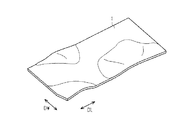
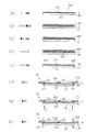
図1が示すように、蒸着マスク用基材1は、帯状を有した金属板である。蒸着マスク用基材1は、短手方向である幅方向DWの各位置で、長手方向DLに繰り返される凹凸を有した波形状を有する。蒸着マスク用基材1の幅方向DWでの各位置は、相互に異なる波形状を有する。なお、図1では、蒸着マスク用基材1が有する形状を説明するために、実際よりも波形状を誇張して示す。蒸着マスク用基材1の有する厚みは、15μm以上50μm以下である。蒸着マスク用基材1の有する厚みの均一性は、例えば、厚みの平均値に対する厚みの最大値と厚みの最小値との差分の比率が、5%以下である。[Configuration of substrate for vapor deposition mask]
As FIG. 1 shows, the
蒸着マスク用基材1を構成する材料は、ニッケル、もしくは、鉄ニッケル合金であり、例えば、30質量%以上のニッケルを含む鉄ニッケル合金、なかでも、36質量%ニッケルと64質量%鉄との合金を主成分とする、すなわちインバーであることが好ましい。36質量%ニッケルと64質量%鉄との合金を主成分とする場合、残余分はクロム、マンガン、炭素、コバルトなどの添加物を含む。蒸着マスク用基材1を構成する材料が、インバーである場合、蒸着マスク用基材1の熱膨張係数は、例えば、1.2×10⁻⁶/℃程度である。このような熱膨張係数を有する蒸着マスク用基材1であれば、蒸着マスク用基材1から製造されるマスクでの熱膨張による大きさの変化と、ガラス基板での熱膨張による大きさの変化とが同じ程度であるため、蒸着対象の一例として、ガラス基板を用いることが好適である。The material constituting the vapor
[伸び差率]
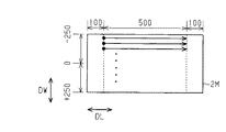
図2が示すように、蒸着マスク用基材1の幅方向DWでの各位置において、蒸着マスク用基材1の表面での長手方向DLの長さは、表面距離Lである。表面距離Lの計測では、まず、蒸着マスク用基材1が幅方向DWの全体(全幅)において切断されるスリット工程が実施されて、蒸着マスク用基材1の長手方向DLにおける一部分として、測定用基材2Mが切り出される。測定用基材2Mの幅方向DWでの寸法Wは、蒸着マスク用基材1の幅方向DWでの寸法と等しい。次いで、測定用基材2Mの表面2Sについて、長手方向DLの各位置での高さが計測される。長手方向DLの各位置での高さが計測される範囲である計測範囲ZLは、測定用基材2Mの長手方向DLでの両方の端部である非計測範囲ZEを除く範囲である。各非計測範囲ZEが有する長手方向DLでの長さは、蒸着マスク用基材1を切断するスリット工程によって、蒸着マスク用基材1とは異なる波形状を有する可能性を有した範囲であり、高さの測定から除外される範囲である。各非計測範囲ZEが有する長手方向DLでの長さは、例えば、100mmである。[Elongation difference]
As shown in FIG. 2, the length in the longitudinal direction DL on the surface of the vapor
図3は、測定用基材2Mの長手方向DLの各位置での高さの一例を示すグラフであり、測定用基材2Mの長手方向DLを含む断面での断面構造と共に高さを示す図である。
FIG. 3 is a graph showing an example of the height of each position of the
図3が示すように、高さが測定される長手方向DLの各位置は、蒸着マスク用基材1が有する波形状の凹凸を引き写すことの可能な間隔で並ぶ。高さが測定される長手方向DLの各位置は、例えば、長手方向DLに1mmの間隔で並ぶ。長手方向DLでの各位置の高さを結ぶ折れ線LCの長さは、表面距離Lとして算出される。蒸着マスク用基材1の伸び差率は、式1によって定められる。すなわち、蒸着マスク用基材1の幅方向DWでの各位置の表面距離Lのなかの最小値を最小表面距離Lmとすると、最小表面距離Lmに対する各表面距離Lと最小表面距離Lmとの差分の比率が、伸び差率である。
伸び差率=(L−Lm)/Lm ・・・(式1)As shown in FIG. 3, the positions in the longitudinal direction DL at which the height is measured are arranged at intervals at which the corrugated irregularities of the vapor
Difference in elongation = (L−Lm) / Lm (Formula 1)
図4は、蒸着マスク用基材1の幅方向DWでの各位置の伸び差率を示す。図4の上段に示す実線は、幅方向DWでの中央部の伸び差率が他の部分よりも大きい一例であり、図4の下段に示す実線は、幅方向DWでの一端部の伸び差率が他の部分よりも大きい一例である。
FIG. 4 shows the elongation difference rate at each position in the width direction DW of the
図4が示すように、蒸着マスク用基材1の伸び差率は、幅方向DWの中央部RCで極大値を有し、中央部RCと端部REとの境界の付近で極小値を有する。そして、蒸着マスク用基材1の伸び差率は、中央部RCから幅方向DWの両方の端部REに向けて増大する。幅方向DWの中央部RCは、蒸着マスク用基材1の幅方向DWでの中心PCを、中央部RCの幅方向DWでの中心とする。幅方向DWの中央部RCが有する幅方向DWでの長さは、蒸着マスク用基材1が有する幅方向DWでの長さの40%である。幅方向DWの各端部REが有する幅方向DWでの長さは、蒸着マスク用基材1が有する幅方向DWでの長さの30%である。こうした蒸着マスク用基材1の伸び差率は、以下の3つの条件を満たす。
As shown in FIG. 4, the elongation difference rate of the vapor
[条件1]両方の端部REのなかの少なくとも一方での伸び差率は、幅方向DWの中央部RCでの伸び差率よりも小さい。
[条件2]中央部RCが有する伸び差率は、3×10⁻⁵以下である。
[条件3]両方の端部REが有する伸び差率は、15×10−5以下である。なお、両方の端部REが有する伸び差率は、好ましくは、10×10−5以下である。[Condition 1] The elongation difference rate of at least one of both end portions RE is smaller than the elongation difference rate of the central portion RC in the width direction DW.
[Condition 2] The elongation difference of the central portion RC is 3 × 10 −5 or less.
[Condition 3] The elongation difference ratio of both end portions RE is 15 × 10 −5 or less. Note that the elongation difference ratio of both end portions RE is preferably 10 × 10 −5 or less.
図4の上段の実線が示すように、条件1を満たす例として、各端部REでの伸び差率が中央部RCでの伸び差率よりも小さい蒸着マスク用基材1では、中央部RCの表面での凹凸の繰り返される数や、中央部RCの表面での段差が、各端部REよりも大きい。こうした蒸着マスク用基材1は、蒸着マスク用基材1の表面に供給される液体を、中央部RCから各端部REへ、さらに、各端部REから蒸着マスク用基材1の外側へ流しやすい。
As shown by the solid line in the upper stage of FIG. 4, as an example satisfying the
図4の下段の実線が示すように、条件1を満たす他の例として、一方の端部REでの伸び差率のみが中央部RCでの伸び差率よりも小さい蒸着マスク用基材1では、一方の端部REの表面での凹凸の繰り返される数や、一方の端部REの表面での段差が、中央部RCや他方の端部REよりも大きい。こうした蒸着マスク用基材1は、蒸着マスク用基材1の表面に供給される液体を、一方の端部REから他方の端部REへ、さらに、他方の端部REから蒸着マスク用基材1の外側へ流しやすい。
As shown in the lower solid line in FIG. 4, as another example that satisfies the
蒸着マスク用基材1の表面に供給される液体は、例えば、蒸着マスク用基材1の表面に位置するレジスト層を現像するための現像液、現像液を表面から除去するための洗浄液である。また、蒸着マスク用基材1の表面に供給される液体は、例えば、蒸着マスク用基材1をエッチングするためのエッチング液、エッチング液を表面から除去するための洗浄液である。また、蒸着マスク用基材1の表面に供給される液体は、例えば、蒸着マスク用基材1の表面にエッチング後に残存するレジスト層を剥離するための剥離液、剥離液を表面から除去するための洗浄液である。そして、蒸着マスク用基材1の表面に供給された液体の流れに淀みを生じがたい上記各構成であれば、液体による処理を用いた加工の均一性を、蒸着マスク用基材1の表面内で高めることが可能となる。
The liquid supplied to the surface of the vapor
なお、条件1を満たさない例として、各端部REでの伸び差率が中央部RCでの伸び差率よりも大きい蒸着マスク用基材1では、蒸着マスク用基材1の表面に供給された液体が、各端部REから蒸着マスク用基材1の外側へ流れやすい一方で、各端部REから中央部RCへも流れやすい。結果として、中央部RCに液だまりを生じやすく、液体による処理を用いた加工の均一性を、蒸着マスク用基材1の表面内で低下させる要因となる。このように、条件1を満たす構成、および、それによって得られる効果は、中央部RCでの伸び差率と各端部REでの伸び差率との差によって発生する、液体を用いた表面の加工での課題を認識することによって、はじめて導き出されることである。
As an example that does not satisfy the
[マスク装置の構成]
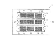
図5は、蒸着マスク用基材1を用いて製造される蒸着マスクを備えるマスク装置の概略的な平面構造を示す平面図である。図6は、蒸着マスクが備えるマスク部の断面構造の一例を示す断面図であり、図7は、蒸着マスクが備えるマスク部の断面構造の他の例を示す断面図である。なお、マスク装置が備える蒸着マスクの数量や、蒸着マスク30が備えるマスク部の数量は、一例である。[Configuration of mask device]
FIG. 5 is a plan view showing a schematic planar structure of a mask device provided with a vapor deposition mask manufactured using the vapor
図5が示すように、マスク装置10は、メインフレーム20と、3つの蒸着マスク30とを備える。メインフレーム20は、複数の蒸着マスク30を支持する矩形枠状を有し、蒸着を行うための蒸着装置に取り付けられる。メインフレーム20は、各蒸着マスク30が位置する範囲のほぼ全体にわたり、メインフレーム20を貫通するメインフレーム孔21を有する。
As shown in FIG. 5, the
各蒸着マスク30は、帯板状を有した複数のフレーム部31と、各フレーム部31に3つずつのマスク部32とを備える。フレーム部31は、マスク部32を支持する短冊板状を有して、メインフレーム20に取り付けられる。フレーム部31は、マスク部32が位置する範囲のほぼ全体にわたり、フレーム部31を貫通するフレーム孔33を有する。フレーム部31は、マスク部32よりも高い剛性を有し、かつ、フレーム孔33を囲う枠状を有する。各マスク部32は、フレーム孔33を区画するフレーム部31のフレーム内縁部に1つずつ、溶着や接着によって固定される。
Each
図6が示すように、マスク部32の一例は、マスク板323から構成される。マスク板323は、蒸着マスク用基材1から形成された1枚の板部材であってもよいし、蒸着マスク用基材1から形成された1枚の板部材と樹脂板との積層体であってもよい。
As shown in FIG. 6, an example of the
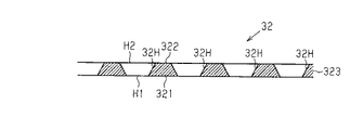
マスク板323は、第1面321と、第1面321とは反対側の面である第2面322とを備える。第1面321は、マスク装置10が蒸着装置に取り付けられた状態で、ガラス基板などの蒸着対象と対向する。第2面322は、蒸着装置の蒸着源と対向する。マスク部32は、マスク板323を貫通する複数の孔32Hを有する。孔32Hの壁面は、マスク板323の厚み方向に対して、断面視において傾きを有する。孔32Hの壁面の形状は、断面視において、図6が示すような直線状であってもよいし、孔32Hの外側に向けて張り出す半円弧状であってもよいし、複数の屈曲点を有する複雑な曲線状であってもよい。
The
マスク板323の厚みは、1μm以上50μm以下であり、好ましくは、2μm以上20μm以下である。マスク板323の厚みが50μm以下であれば、マスク板323に形成される孔32Hの深さを50μm以下とすることが可能である。このように、薄いマスク板323であれば、孔32Hが有する壁面の面積そのものを小さくして、孔32Hの壁面に付着する蒸着物質の量を低下させる。
The thickness of the
第2面322は、孔32Hの開口である第2開口H2を含み、第1面321は、孔32Hの開口である第1開口H1を含む。第2開口H2は、平面視において、第1開口H1よりも大きい。各孔32Hは、蒸着源から昇華した蒸着物質が通る通路であって、蒸着源から昇華した蒸着物質は、第2開口H2から第1開口H1に向けて進む。第2開口H2が第1開口H1よりも大きい孔32Hであれば、第2開口H2から孔32Hに入る蒸着物質の量を増やすことが可能となる。なお、第1面321に沿う断面での孔32Hの面積は、第1開口H1から第2開口H2に向けて、第1開口H1から第2開口H2まで単調に増大してもよい。
The
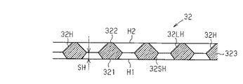
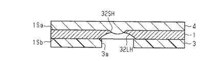
図7が示すように、マスク部32の他の例は、マスク板323を貫通する複数の孔32Hを有する。第2開口H2は、平面視において、第1開口H1よりも大きい。孔32Hは、第2開口H2を有する大孔32LHと、第1開口H1を有する小孔32SHとから構成される。大孔32LHの断面積は、第2開口H2から第1面321に向けて、単調に減少する。小孔32SHの断面積は、第1開口H1から第2面322に向けて、単調に減少する。孔32Hの壁面は、断面視において、大孔32LHと小孔32SHとが接続する部位、すなわち、マスク板323の厚み方向の中間で、孔32Hの内側に向けて突き出た形状を有する。孔32Hの壁面にて突き出た部位と、第1面321との間の距離は、ステップハイトSHである。図6で説明した断面構造の例では、ステップハイトSHがゼロである。第1開口H1に到達する蒸着物質の量を確保しやすい観点では、ステップハイトSHがゼロである構成が好ましい。なお、ステップハイトSHがゼロであるマスク部32を得る構成では、蒸着マスク用基材1の片面からのウェットエッチングで孔32Hが形成される程度に、マスク板323の厚みは薄く、例えば50μm以下である。
As shown in FIG. 7, another example of the
[マスク部の接合構造]
図8は、マスク部32とフレーム部31との接合構造が有する断面構造の一例を示す。図9は、マスク部32とフレーム部31との接合構造が有する断面構造の他の例を示す。[Masked joint structure]
FIG. 8 shows an example of a cross-sectional structure of the joint structure between the
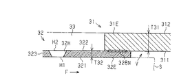
図8が示す例のように、マスク板323の外縁部32Eは、孔32Hを備えない領域である。マスク板323が有する第2面322のなかでマスク板323の外縁部32Eに含まれる部分は、マスク部が備える側面の一例であり、フレーム部31に接合される。フレーム部31は、フレーム孔33を区画する内縁部31Eを備える。内縁部31Eは、マスク板323と対向する接合面311と、接合面311とは反対側の面である非接合面312とを備える。内縁部31Eの厚みT31、すなわち、接合面311と非接合面312との距離は、マスク板323が有する厚みT32よりも十分に厚く、それによって、マスク板323よりも高い剛性をフレーム部31は有する。特に、フレーム部31は、内縁部31Eが自重によって垂れ下がることや、内縁部31Eがマスク部32に向けて変位することに対して、高い剛性を有する。内縁部31Eの接合面311は、第2面322と接合された接合部32BNを備える。
As in the example illustrated in FIG. 8, the
接合部32BNは、内縁部31Eのほぼ全周にわたり、連続的、あるいは、間欠的に位置する。接合部32BNは、接合面311と第2面322との溶着によって形成される溶着痕であってもよいし、接合面311と第2面322とを接合する接合層であってもよい。フレーム部31は、内縁部31Eの接合面311と、マスク板323の第2面322とを接合すると共に、マスク板323がそれの外側に向けて引っ張られるような応力Fを、マスク板323に加える。なお、フレーム部31もまた、それの外側に向けて引っ張られるような応力を、マスク板323での応力Fと同じ程度に、メインフレーム20によって加えられる。そのため、メインフレーム20から取り外された蒸着マスク30では、メインフレーム20とフレーム部31との接合による応力が解除され、マスク板323に加わる応力Fも緩和される。接合面311での接合部32BNの位置は、マスク板323に応力Fを等方的に作用させる位置であることが好ましく、マスク板323の形状、および、フレーム孔33の状に基づき、適宜選択される。
The joint portion 32BN is located continuously or intermittently over substantially the entire circumference of the
接合面311は、接合部32BNが位置する平面であり、第2面322の外縁部32Eからマスク板323の外側に向けて広がる。言い換えれば、内縁部31Eは、第2面322がそれの外側へ擬似的に拡張された面構造を備え、第2面322の外縁部32Eから、マスク板323の外側に向けて広がる。そのため、接合面311が広がる範囲では、マスク板323の厚みに相当する空間Vが、マスク板323の周囲に形成されやすい。結果として、マスク板323の周囲では、蒸着対象Sとフレーム部31とが物理的に干渉することを抑えることが可能となる。
The
図9が示す例においても、第2面322の外縁部32Eは、孔32Hが形成されていない領域を備える。第2面322の外縁部32Eは、接合部32BNによる接合を通じて、フレーム部31が備える接合面311に接合される。そして、フレーム部31は、マスク板323がそれの外側に向けて引っ張られるような応力Fを、マスク板323に加えると共に、接合面311が広がる範囲において、マスク板323の厚みに相当する空間Vを形成する。
Also in the example illustrated in FIG. 9, the
[マスク部の数量]
図10は、蒸着マスク30が備える孔32Hの数量と、マスク部32が備える孔32Hの数量との関係の一例を示す。また、図11は、蒸着マスク30が備える孔32Hの数量と、マスク部32が備える孔32Hの数量との関係の他の例を示す。[Quantity of mask part]
FIG. 10 shows an example of the relationship between the number of
図10(a)の例が示すように、フレーム部31は、3つのフレーム孔33を有する。図10(b)の例が示すように、蒸着マスク30は、各フレーム孔33に1つずつマスク部32を備える。フレーム孔33Aを区画する内縁部31Eは、1つのマスク部32Aと接合し、フレーム孔33Bを区画する内縁部31Eは、他の1つのマスク部32Bと接合し、フレーム孔33Cを区画する内縁部31Eは、他の1つのマスク部32Cと接合する。
As shown in the example of FIG. 10A, the
ここで、蒸着マスク30は、複数の蒸着対象に対して、繰り返して用いられる。そのため、蒸着マスク30が備える各孔32Hは、孔32Hの位置や、孔32Hの構造などに高い精度を求められる。図10が示す構成のように、1つのフレーム部31に必要とされる孔32Hの数量を、3つのマスク部32で分割して担う構成であれば、1つのマスク部32の一部に変形を生じた場合であっても、1つのフレーム部31に必要とされる孔32Hの数量を、単一のマスク部で担う構成と比べて、変形したマスク部32と交換される新たなマスク部32の大きさを、小さくすることが可能である。そして、蒸着マスク30の製造や蒸着マスク30の補修、これらに要する各種材料の消費量を抑えることが可能ともなる。なお、孔32Hの位置や、孔32Hの構造に関する検査は、応力Fが加えられた状態、すなわち、フレーム部31にマスク部32が接合された状態で行われることが好ましい。こうした観点において、上述した接合部32BNは、変形したマスク部32を新たなマスク部32に交換することを可能とする構成が好ましい。そして、マスク部32を構成するマスク板323の厚みが薄いほど、また、孔32Hが小さいほど、マスク部32の歩留まりは下がる。そのため、各フレーム孔33に1つずつのマスク部32を備える構成は、マスク部32に高精細が求められる蒸着マスク30に対して、特に好適でもある。
Here, the
図11(a)の例が示すように、フレーム部31は、3つのフレーム孔33を有する。図11(b)の例が示すように、蒸着マスク30は、各フレーム孔33に共通する1つのマスク部32を備える。フレーム孔33Aを区画する内縁部31E、フレーム孔33Bを区画する内縁部31E、フレーム孔33Cを区画する内縁部31Eは、これらに共通する1つのマスク部32と接合する。
As shown in the example of FIG. 11A, the
なお、1つのフレーム部31に必要とされる孔32Hの数量を、1つのマスク部32で担う構成であれば、フレーム部31に接合されるマスク部32の数量を1つとすることが可能であるため、フレーム部31とマスク部32との接合に要する負荷を軽減することが可能である。そして、マスク部32を構成するマスク板323の厚みが厚いほど、また、孔32Hのサイズが大きいほど、マスク部32の歩留まりが上がりやすい。そのため、各フレーム孔33に共通するマスク部32を備える構成は、マスク部32に低解像度が求められる蒸着マスク30に対して好適でもある。
In addition, if the number of
[蒸着マスク用基材の製造方法]
図12、および、図13は、蒸着マスク用基材の製造方法に圧延を用いて製造する例を示す。
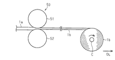
図12が示すように、蒸着マスク用基材の製造方法では、まず、インバーなどから形成された母材1aであって、長手方向DLに延びる母材1aを準備する。次いで、母材1aの長手方向DLと、母材1aを搬送する搬送方向とが平行になるように、一対の圧延ローラー51,52を備える圧延装置50に向けて母材1aを搬送する。母材1aが一対の圧延ローラー51,52の間に到達すると、一対の圧延ローラー51,52によって母材1aが圧延される。これによって、母材1aが長手方向DLに伸ばされることで、圧延材1bを得ることができる。圧延材1bはコアCに巻き取られるが、圧延材1bは、コアCに巻き取られることなく、帯形状に伸ばされた状態で取り扱われてもよい。圧延材1bの厚みは、例えば、10μm以上50μm以下である。この際、上述した条件1,2,3が満たされるように、圧延ローラー51,52の間での押圧力と、圧延ローラー51,52の回転速度とが設定される。[Method for producing substrate for vapor deposition mask]
FIG. 12 and FIG. 13 show an example of manufacturing by using rolling as a method for manufacturing a base material for a vapor deposition mask.
As shown in FIG. 12, in the manufacturing method of the evaporation mask base material, first, a base material 1a formed from invar or the like and extending in the longitudinal direction DL is prepared. Next, the base material 1a is transported toward a rolling
図13が示すように、圧延材1bの内部に蓄積された残留応力を取り除くために、アニール装置53を用いて圧延材1bをアニールする。これによって、蒸着マスク用基材1が得られる。圧延材1bのアニールは、圧延材1bを長手方向DLに引っ張りながら行うため、アニール前の圧延材1bに比べて残留応力が低減された蒸着マスク用基材1を得ることができる。なお、圧延工程およびアニール工程の各々を、以下のように変更して実施してもよい。すなわち、例えば、圧延工程では、複数の対の圧延ローラーを備える圧延装置を用いてもよい。また、圧延工程およびアニール工程を複数回繰り返すことによって、蒸着マスク用基材1を製造してもよい。また、アニール工程では、圧延材1bを長手方向DLに引っ張りながら行うのではなく、コアCに巻き取られた状態の圧延材1bに対して行ってもよい。
As shown in FIG. 13, in order to remove the residual stress accumulated in the rolled
なお、コアCに巻き取られた状態の圧延材1bに対してアニール工程を行ったときには、蒸着マスク用基材1がコアCに巻き取られたことによって、アニール後の蒸着マスク用基材1には、蒸着マスク用基材1がコアCに巻かれたときの径に応じた反りの癖がついてしまう場合がある。そのため、蒸着マスク用基材1がコアCに巻かれたときの径の大きさや母材1aを形成する材料によっては、圧延材1bを長手方向DLに引っ張りながら圧延材1bをアニールすることが好ましい。
When the annealing process is performed on the rolled
蒸着マスク用基材1の製造方法に電解を用いる場合には、電解に用いられる電極表面に蒸着マスク用基材1が形成され、その後、電極表面から蒸着マスク用基材1が離型される。蒸着マスク用基材1を構成する材料がインバーである場合、電解に用いられる電解浴は、鉄イオン供給剤、ニッケルイオン供給剤、および、pH緩衝剤を含む。電解に用いられる電解浴は、応力緩和剤、Fe3+イオンマスク剤、リンゴ酸やクエン酸などの錯化剤などを含んでもよく、電解に適したpHに調整された弱酸性の溶液である。鉄イオン供給剤は、例えば、硫酸第一鉄・7水和物、塩化第一鉄、スルファミン酸鉄などである。ニッケルイオン供給剤は、例えば、硫酸ニッケル(II)、塩化ニッケル(II)、スルファミン酸ニッケル、臭化ニッケルである。pH緩衝剤は、例えば、ホウ酸、マロン酸である。マロン酸は、Fe3+イオンマスク剤としても機能する。応力緩和剤は、例えばサッカリンナトリウムである。電解に用いられる電解浴は、例えば、上述した添加剤を含む水溶液であり、5%硫酸、あるいは、炭酸ニッケルなどのpH調整剤によって、例えば、pHが2以上3以下となるように調整される。When electrolysis is used in the method for manufacturing the
電解に用いられる電解条件は、蒸着マスク用基材1が有する厚み、蒸着マスク用基材1における組成比などが、電解浴の温度、電流密度、および、電解時間によって調整された条件である。上述した電解浴を用いた電解条件における陽極は、例えば、純鉄とニッケルである。電解条件における陰極は、例えば、SUS304などのステンレス板である。電解浴の温度は、例えば、40℃以上60℃以下である。電流密度は、例えば、1A/dm2以上4A/dm2以下である。この際、上述した条件1,2,3が満たされるよう、電極表面での電流密度が設定される。The electrolysis conditions used for electrolysis are conditions in which the thickness of the
なお、電解によって得られた蒸着マスク用基材1や、圧延によって得られた蒸着マスク用基材1は、化学的な研磨によって薄く加工されてもよいし、電気的な研磨によって薄く加工されてもよい。化学的な研磨に用いられる研磨液は、例えば、過酸化水素を主成分とした鉄系合金用の化学研磨液である。電気的な研磨に用いられる電解液は、過塩素酸系の電解研磨液や硫酸系の電解研磨液である。この際、上述した条件1,2,3が満たされるため、研磨液による研磨の結果や、洗浄液による研磨液の洗浄の結果について、蒸着マスク用基材1の表面でのばらつきが抑えられる。
The
[マスク部の製造方法]
図7に示したマスク部32を製造するための工程について図14から図19を参照して説明する。なお、図6で説明したマスク部32を製造するための工程は、図7で説明したマスク部32を製造するための工程にて、小孔32SHを貫通孔として、大孔32LHを形成するための工程を割愛した工程と同様であるため、その重複する説明を割愛する。[Manufacturing method of mask part]
A process for manufacturing the
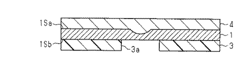
図14が示すように、マスク部を製造するときには、まず、第1面1Saと第2面1Sbとを含む蒸着マスク用基材1と、第1面1Saに貼り付けられる第1ドライフィルムレジスト2と、第2面1Sbに貼り付けられる第2ドライフィルムレジスト3とを準備する。2つのドライフィルムレジスト2,3の各々は、蒸着マスク用基材1とは別に形成されたフィルムである。次いで、第1面1Saに第1ドライフィルムレジスト2を貼り付け、かつ、第2面1Sbに第2ドライフィルムレジスト3を貼り付ける。
As shown in FIG. 14, when manufacturing a mask portion, first, a
図15が示すように、ドライフィルムレジスト2,3のうち、孔を形成する部位以外の部分を露光し、露光後のドライフィルムレジストを現像する。これによって、第1ドライフィルムレジスト2に第1貫通孔2aを形成し、かつ、第2ドライフィルムレジスト3に第2貫通孔3aを形成する。第1ドライフィルムレジスト2を露光するときには、第1ドライフィルムレジスト2において蒸着マスク用基材1に接する面とは反対側の面に、第1貫通孔2aを形成する部分以外の部分に光を到達させるように構成された原版を載せる。第2ドライフィルムレジスト3を露光するときには、第2ドライフィルムレジスト3において蒸着マスク用基材1に接する面とは反対側の面に、第2貫通孔3aを形成する部分以外の部分に光を到達させるように構成された原版を載せる。また、露光後のドライフィルムレジストを現像するときには、現像液として、例えば炭酸ナトリウム水溶液を用いる。この際、上述した条件1,2,3が満たされるため、現像液による現像の結果や、その洗浄液による洗浄の結果について、蒸着マスク用基材1の表面でのばらつきを抑えられる。結果として、第1貫通孔2aの形状や大きさ、また、第2貫通孔3aの形状や大きさに関して、蒸着マスク用基材1の表面内での均一性を高めることが可能となる。
As shown in FIG. 15, portions of the dry film resists 2 and 3 other than the portions where holes are formed are exposed and the exposed dry film resist is developed. Thus, the first through
図16が示すように、例えば、第1ドライフィルムレジスト2をマスクとして、塩化第二鉄液を用いて蒸着マスク用基材1の第1面1Saをエッチングする。このとき、第2ドライフィルムレジスト3には、蒸着マスク用基材1の第2面1Sbが第1面1Saと同時にエッチングされないように、第2保護層61を形成する。第2保護層61の形成材料は、塩化第二鉄液によってエッチングされにくい材料であればよい。これによって、蒸着マスク用基材1の第1面1Saに、第1ドライフィルムレジスト2の第1貫通孔2aを介して、第2面1Sbに向けて窪む小孔32SHを形成する。小孔32SHは、第1面1Saに開口する第1開口H1を有する。この際、上記条件1,2,3が満たされるため、エッチング液によるエッチングの結果や、その洗浄液による洗浄の結果について、蒸着マスク用基材1の表面でのばらつきを抑えられる。結果として、小孔32SHの形状や大きさに関して、蒸着マスク用基材1の表面内での均一性を高めることが可能となる。
As shown in FIG. 16, for example, the first surface 1Sa of the
蒸着マスク用基材1をエッチングするエッチング液は、酸性のエッチング液であって、蒸着マスク用基材1がインバーから構成される場合には、インバーをエッチングすることが可能なエッチング液であればよい。酸性のエッチング液は、例えば、過塩素酸第二鉄液、および、過塩素酸第二鉄液と塩化第二鉄液との混合液に対して、過塩素酸、塩酸、硫酸、蟻酸、および、酢酸のいずれかを混合した溶液である。蒸着マスク用基材1をエッチングする方法は、蒸着マスク用基材1を酸性のエッチング液に浸漬するディップ式であってもよいし、蒸着マスク用基材1に酸性のエッチング液を吹き付けるスプレー式であってもよい。
The etching solution for etching the
図17が示すように、蒸着マスク用基材1の第1面1Saに形成した第1ドライフィルムレジスト2と、第2ドライフィルムレジスト3に接する第2保護層61とを取り除く。また、蒸着マスク用基材1の第1面1Saに、第1面1Saのエッチングを防ぐための第1保護層4を形成する。第1保護層4の形成材料は、塩化第二鉄液によってエッチングされにくい材料であればよい。
As shown in FIG. 17, the first dry film resist 2 formed on the first surface 1Sa of the vapor
図18が示すように、第2ドライフィルムレジスト3をマスクとして、塩化第二鉄液を用いて蒸着マスク用基材1の第2面1Sbをエッチングする。これによって、蒸着マスク用基材1の第2面1Sbに、第2ドライフィルムレジスト3の第2貫通孔3aを介して、第1面1Saに向けて窪む大孔32LHを形成する。大孔32LHは、第2面1Sbに開口する第2開口H2を有し、第2面1Sbと対向する平面視において、第2開口H2は、第1開口H1よりも大きい。この際、上記条件1,2,3が満たされるため、エッチング液によるエッチングの結果や、洗浄液によるエッチング液の洗浄の結果について、蒸着マスク用基材1の表面でのばらつきが抑えられる。結果として、大孔32LHの形状や大きさについて、蒸着マスク用基材1の表面内での均一性を高めることが可能となる。この際に用いられるエッチング液もまた、酸性のエッチング液であって、蒸着マスク用基材1がインバーから構成される場合には、インバーをエッチングすることが可能なエッチング液であればよい。蒸着マスク用基材1をエッチングする方法もまた、蒸着マスク用基材1を酸性のエッチング液に浸漬するディップ式であってもよいし、蒸着マスク用基材1に酸性のエッチング液を吹き付けるスプレー式であってもよい。
As shown in FIG. 18, using the second dry film resist 3 as a mask, the second surface 1Sb of the
図19が示すように、第1保護層4と第2ドライフィルムレジスト3とを蒸着マスク用基材1から取り除くことによって、複数の小孔32SHと、各小孔32SHに繋がる大孔32LHとが形成されたマスク部32が得られる。
As shown in FIG. 19, by removing the first
なお、蒸着マスク用基材1を形成するための圧延用の母材1aが形成されるとき、通常、圧延用の母材を形成するための材料中に混入した酸素を除くために、例えば、粒状のアルミニウムやマグネシウムなどの脱酸剤が、母材を形成するための材料に混ぜられる。アルミニウムやマグネシウムは、酸化アルミニウムや酸化マグネシウムなどの金属酸化物として母材に含まれる。これら金属酸化物の大部分は、母材が圧延される前に、母材から取り除かれる。一方で、金属酸化物の一部分は、圧延の対象となる母材に残る。この点、蒸着マスク用基材1の製造に電解を用いる製造方法によれば、金属酸化物がマスク部32に混ざることが抑えられる。
When the rolling base material 1a for forming the vapor deposition
[蒸着マスクの製造方法]
蒸着マスクの製造方法の各例を説明する。なお、図20を参照して、ウェットエッチングによって孔を形成する方法を用いた一例を説明する。また、図21を参照して、電解によって孔を形成する方法を用いた一例を説明し、図22を参照して、電解によって孔を形成する方法を用いた他の例を説明する。また、図6で説明したマスク部32を用いる蒸着マスクを製造する方法と、図7で説明したマスク部32を備える蒸着マスクを製造する方法とは、基材32Kに対して行われるエッチングの形態が異なるが、それ以外の工程はほぼ同様である。以下では、図6で説明したマスク部32を備える蒸着マスクの製造方法を主に説明し、図7で説明したマスク部32を備える蒸着マスクの製造方法に関しては、その重複した説明を省略する。[Method of manufacturing vapor deposition mask]
Each example of the manufacturing method of a vapor deposition mask is demonstrated. An example using a method of forming holes by wet etching will be described with reference to FIG. In addition, an example using a method of forming holes by electrolysis will be described with reference to FIG. 21, and another example using a method of forming holes by electrolysis will be described with reference to FIG. Moreover, the method of manufacturing the vapor deposition mask using the
図20(a)〜(h)が示す例のように、蒸着マスクの製造方法の一例では、まず、基材32Kが準備される(図20(a)参照)。なお、基材32Kは、マスク板323として加工される上述した蒸着マスク用基材1の他に、その蒸着マスク用基材1を支持するための支持体SPをさらに備えることが好ましい。なお、基材32Kの第1面321は、上述した第1面1Saに相当し、基材32Kの第2面322は、上述した第2面1Sbに相当する。
As in the example shown in FIGS. 20A to 20H, in the example of the method for manufacturing the vapor deposition mask, first, the
次いで、基材32Kが有する第2面322にレジスト層PRが形成され(図20(b)参照)、レジスト層PRに対する露光、および、現像が行われることによって、第2面322にレジストマスクRMが形成される(図20(c)参照)。次に、レジストマスクRMを用いた第2面322からのウェットエッチングによって、基材32Kに孔32Hが形成される(図20(d)参照)。この際、ウェットエッチングが開始される第2面322には、第2開口H2が形成され、それよりも遅れてエッチングが行われる第1面321には、第2開口H2よりも小さい第1開口H1が形成される。次いで、レジストマスクRMが第2面322から除去されることによって、上述したマスク部32が製造される(図20(e)参照)。最後に、第2面322における外縁部32Eがフレーム部31の内縁部31Eに接合され、マスク部32から支持体SPが離型されることによって、蒸着マスク30が製造される(図20(f)から(h)参照)。
Next, a resist layer PR is formed on the
なお、図7で説明したマスク部32を備える蒸着マスクの製造方法では、上述した工程が、支持体SPを有さない基材32Kにおいて、第1面321に対応する基材32Kの面に施され、それによって、小孔32SHが形成される。次いで、小孔32SHを保護するためのレジストなどが小孔32SHに充填される。続いて、上述した工程が、第2面322に対応する基材32Kの面に施され、それによって、マスク部32が製造される。
In the method of manufacturing the vapor deposition mask including the
図20(f)が示す例では、第2面322の外縁部32Eをフレーム部31の内縁部31Eに接合する方法として、抵抗溶接が用いられる。この際、絶縁性を有した支持体SPに、複数の孔SPHが形成される。各孔SPHは、支持体SPのなかで、接合部32BNとなる部位と対向する部位に形成される。そして、マスク部32に対してそれの外側に向けた応力が加えられた状態で、孔SPHを通じた通電によって、間欠的な接合部32BNが形成され、それによって、外縁部32Eと内縁部31Eとが溶着する。
In the example shown in FIG. 20 (f), resistance welding is used as a method of joining the
図20(g)が示す例では、第2面322の外縁部32Eをフレーム部31の内縁部31Eに接合する方法として、レーザー溶接が用いられる。この際、光透過性を有した支持体SPが用いられ、支持体SPを通じて、接合部32BNとなる部位にレーザー光が照射される。そして、間欠的なレーザー光が照射されることによって、間欠的な接合部32BNが形成され、あるいは、連続的にレーザー光が照射され続けることによって、連続的な接合部32BNが形成され、これによって、外縁部32Eと内縁部31Eとが溶着する。なお、マスク部32に対してそれの外側に向けた応力が加えられた状態で、支持体SPがマスク部32を支持する場合には、マスク部32に対する応力の印加を、この溶接では割愛することも可能である。
In the example shown in FIG. 20G, laser welding is used as a method of joining the
図20(h)が示す例では、第2面322の外縁部32Eをフレーム部31の内縁部31Eに接合する方法として、超音波溶接が用いられる。この際、外縁部32Eと内縁部31Eとが、クランプCPなどで挟持され、接合部32BNとなる部位に超音波が印加される。超音波が直接印加される部材は、フレーム部31であってもよいし、マスク部32であってもよい。なお、超音波溶接が用いられた場合には、フレーム部31や支持体SPに、クランプCPによる圧着痕が形成される。
In the example shown in FIG. 20H, ultrasonic welding is used as a method of joining the
なお、図8、および、図9で説明した蒸着マスクは、図21(a)〜(e)で示す他の例、あるいは、図22(a)〜(f)で示す他の例によって製造することも可能である。 The vapor deposition mask described with reference to FIGS. 8 and 9 is manufactured according to another example illustrated in FIGS. 21A to 21E or another example illustrated in FIGS. 22A to 22F. It is also possible.
図21(a)〜(e)が示す例のように、蒸着マスクの製造方法の他の例では、まず、電解に用いられる電極EPの表面である電極表面EPSに、レジスト層PRが形成される(図21(a)参照)。次いで、レジスト層PRに対する露光、および、現像が行われることによって、パターンの一例であるレジストマスクRMが、電極表面EPSに形成される(図21(b)参照)。レジストマスクRMは、電極表面EPSと直交する断面において、電極表面EPSに頂部が位置する逆錐台状を有し、電極表面EPSからの距離が大きいほど、電極表面EPSに沿った断面での面積が大きい形状を有する。次に、レジストマスクRMを有した電極表面EPSを用いる電解が行われ、電極表面EPSのなかでレジストマスクRM以外の領域に広がる金属板がマスク部32として形成される(図21(c)参照)。 As in the example shown in FIGS. 21A to 21E, in another example of the method of manufacturing the vapor deposition mask, first, the resist layer PR is formed on the electrode surface EPS which is the surface of the electrode EP used for electrolysis. (See FIG. 21A). Next, a resist mask RM that is an example of a pattern is formed on the electrode surface EPS by performing exposure and development on the resist layer PR (see FIG. 21B). The resist mask RM has an inverted frustum shape whose top is located on the electrode surface EPS in a cross section orthogonal to the electrode surface EPS, and the area in the cross section along the electrode surface EPS increases as the distance from the electrode surface EPS increases. Has a large shape. Next, electrolysis using the electrode surface EPS having the resist mask RM is performed, and a metal plate extending in a region other than the resist mask RM in the electrode surface EPS is formed as the mask portion 32 (see FIG. 21C). ).
この際、レジストマスクRMが占有する空間以外に金属が堆積して金属板を形成するため、レジストマスクRMの形状に追従した形状を有する孔が、金属板には形成される。そして、マスク部32の孔32Hが、自己整合的に形成される。すなわち、電極表面EPSと接触する面が、第1開口H1を有する第1面321として機能し、第1開口H1よりも大きい開口である第2開口H2を有する最表面が、第2面322として機能する。
At this time, since metal is deposited outside the space occupied by the resist mask RM to form a metal plate, a hole having a shape following the shape of the resist mask RM is formed in the metal plate. Then, the
次に、電極表面EPSからレジストマスクRMのみが除去され、それによって、第1開口H1から第2開口H2までを中空とする孔32Hが形成される(図21(d)参照)。最後に、第2開口H2を有した第2面322の外縁部32Eに、内縁部31Eの接合面311が接合され、次いで、マスク部32を電極表面EPSから剥がすための応力がフレーム部31に加えられる。あるいは、支持体などに接合されたマスク部32が電極表面EPSから剥がされ、そのマスク部32の第2面322における外縁部32Eに、内縁部31Eの接合面311が接合される。それによって、フレーム部31にマスク部32が接合された状態の蒸着マスク30が製造される(図21(e)参照)。
Next, only the resist mask RM is removed from the electrode surface EPS, thereby forming a
図22(a)〜(f)が示す例のように、蒸着マスクの製造方法の他の例では、まず、電解に用いられる電極表面EPSにレジスト層PRが形成される(図22(a)参照)。次いで、レジスト層PRに対する露光、および、現像が行われることによって、パターンの一例であるレジストマスクRMが、電極表面EPSに形成される(図22(b)参照)。レジストマスクRMは、電極表面EPSと直交する断面において、電極表面EPSに底部が位置する錐台状を有し、電極表面EPSからの距離が大きいほど、電極表面EPSに沿った断面での面積が小さい形状を有する。次に、レジストマスクRMを有した電極表面EPSを用いる電解が行われ、電極表面EPSのなかでレジストマスクRM以外の領域に広がる金属板が、マスク部32として形成される(図22(c)参照)。 As in the example shown in FIGS. 22A to 22F, in another example of the method of manufacturing the vapor deposition mask, first, a resist layer PR is formed on the electrode surface EPS used for electrolysis (FIG. 22A). reference). Next, by performing exposure and development on the resist layer PR, a resist mask RM, which is an example of a pattern, is formed on the electrode surface EPS (see FIG. 22B). The resist mask RM has a frustum shape whose bottom is located on the electrode surface EPS in a cross section orthogonal to the electrode surface EPS, and the area of the cross section along the electrode surface EPS increases as the distance from the electrode surface EPS increases. Has a small shape. Next, electrolysis is performed using the electrode surface EPS having the resist mask RM, and a metal plate extending in a region other than the resist mask RM in the electrode surface EPS is formed as the mask portion 32 (FIG. 22C). reference).
ここでも、レジストマスクRMが占有する空間以外に金属が堆積して金属板を形成するため、レジストマスクRMの形状に追従した形状を有する孔が、金属板に形成される。そして、マスク部32における孔32Hが、自己整合的に形成される。すなわち、電極表面EPSと接触する面が、第2開口H2を有する第2面322として機能し、第2開口H2よりも小さい開口である第1開口H1を有する最表面が、第1面321として機能する。
Also here, since metal is deposited outside the space occupied by the resist mask RM to form a metal plate, a hole having a shape following the shape of the resist mask RM is formed in the metal plate. And the
次に、電極表面EPSからレジストマスクRMのみが除去され、それによって、第1開口H1から第2開口H2までを中空とする孔32Hが形成される(図22(d)参照)。そして、第1開口H1を有した第1面321に、中間転写基材TMが接合され、次いで、マスク部32を電極表面EPSから剥がすための応力が中間転写基材TMに加えられる。それによって、中間転写基材TMにマスク部32が接合された状態で、電極表面EPSから第2面322が離される(図22(e)参照)。最後に、第2開口H2を有した第2面322の外縁部32Eに、内縁部31Eの接合面311が接合され、次いで、中間転写基材TMがマスク部32から剥がされる。これによって、フレーム部31にマスク部32が接合された状態の蒸着マスク30が製造される(図22(f)参照)。
Next, only the resist mask RM is removed from the electrode surface EPS, thereby forming a
[実施例]
図23から図29を参照して各実施例を説明する。
[実施例1]
インバーを材料とする母材1aに圧延工程、および、圧延後の金属板から幅方向DWに所望の大きさが得られるように金属板を切断するスリット工程を施す。これによって、圧延材1bを製造し、圧延材1bにアニール工程を施すことによって、幅方向DWの長さが500mmであり、かつ、厚みが20μmである実施例1の蒸着マスク用基材1を得た。次いで、図23が示すように、長手方向DLの長さが700mmである実施例1の測定用基材2Mを、実施例1の蒸着マスク用基材1から切り出した。続いて、切り出された測定用基材2Mの表面距離Lを、測定用基材2Mの幅方向DWの全体にわたり測定し、実施例1の測定用基材2Mでの伸び差率を得た。この際、表面距離Lの測定条件として、以下に示す条件を用いた。
測定装置:株式会社ニコン製 CNC画像測定システム VMR−6555
計測範囲ZLの長手方向DLの長さ :500mm
非計測範囲ZEの長手方向DLの長さ :100mm
長手方向DLの測定間隔 :1mm
幅方向DWの測定間隔 :20mm[Example]
Each embodiment will be described with reference to FIGS.
[Example 1]
The base material 1a made of invar is subjected to a rolling step and a slit step for cutting the metal plate so that a desired size is obtained in the width direction DW from the rolled metal plate. Thereby, the
Measuring device: CNC image measuring system VMR-6555 manufactured by Nikon Corporation
Length in the longitudinal direction DL of the measurement range ZL: 500 mm
Length in the longitudinal direction DL of the non-measurement range ZE: 100 mm
Measurement interval in the longitudinal direction DL: 1 mm
Measurement interval in the width direction DW: 20 mm
実施例1の伸び差率の測定結果を図24、および、表1に示す。なお、表1が示す伸び差率は、中央部RC、および、各端部REでの最大値である。
図24が示すように、実施例1の中央部RCが有する伸び差率の最大値は、2.42×10⁻⁵以下であり、各端部REが有する伸び差率は、10×10−5以下であり、上記条件2,3を満たすことが認められた。そして、実施例1では、幅方向DWの両方の端部REのなかの一方(端部A)での伸び差率の最大値が、4.56×10⁻⁵であり、中央部RCでの伸び差率よりも大きく、幅方向DWの両方の端部REのなかの他方(端部B)での伸び差率の最大値が、1.53×10⁻⁵であり、幅方向DWの中央部RCでの伸び差率よりも小さいことが認められた。すなわち、上記条件1が満たされることが認められた。なお、幅方向DWの各端部REでの伸び差率の最大値の差は、3.03×10⁻⁵であった。The measurement results of the elongation difference rate of Example 1 are shown in FIG. In addition, the elongation difference rate which Table 1 shows is the maximum value in center part RC and each edge part RE.
As shown in FIG. 24, the maximum value of the elongation difference ratio with the central portion RC of the first embodiment, it is 2.42 × 10 -5 or less, elongation Saritsu having each end RE is, 10 × 10 - 5 or less, and it was confirmed that the
[実施例2]
圧延ローラー51,52の間での押圧力を実施例1よりも高め、その他の条件を実施例1の条件と同様に設定することによって、幅方向DWの長さが500mmであり、かつ、厚みが15μmである実施例2の蒸着マスク用基材1を得た。次いで、実施例1と同様に、実施例2の蒸着マスク用基材1から測定用基材2Mを切り出し、切り出された測定用基材2Mの表面距離Lを、測定用基材2Mの幅方向DWの全体にわたり測定して、実施例2の測定用基材2Mでの伸び差率を得た。[Example 2]
By setting the pressing force between the rolling
実施例2の伸び差率の測定結果を図25、および、表1に示す。
図25が示すように、実施例2の中央部RCが有する伸び差率の最大値は、0.75×10⁻⁵であり、各端部REが有する伸び差率の最大値は、0.10×10⁻⁵、および、0.68×10⁻⁵であることが認められた。そして、実施例2では、幅方向DWの両方の端部REの伸び差率が、幅方向DWの中央部RCでの伸び差率よりも小さく、上記条件1,2,3が満たされることが認められた。The measurement results of the differential elongation of Example 2 are shown in FIG.
As shown in FIG. 25, the maximum value of the elongation difference rate that the central portion RC of Example 2 has is 0.75 × 10 −5 , and the maximum value of the elongation difference rate that each end portion RE has is. It was found to be 10 × 10 −5 and 0.68 × 10 −5 . And in Example 2, the elongation difference rate of both edge part RE of the width direction DW is smaller than the elongation difference rate in the center part RC of the width direction DW, and the said
[実施例3]
圧延ローラー51,52の間での押圧力を実施例1よりも高め、かつ、実施例2とは異なる分布とし、その他の条件を実施例1の条件と同様に設定することによって、幅方向DWの長さが500mmであり、かつ、厚みが15μmである実施例3の蒸着マスク用基材1を得た。次いで、実施例1と同様に、実施例3の蒸着マスク用基材1から測定用基材2Mを切り出し、切り出された測定用基材2Mの表面距離Lを、測定用基材2Mの幅方向DWの全体にわたり測定して、実施例3の測定用基材2Mでの伸び差率を得た。[Example 3]
The pressing force between the rolling
実施例3の伸び差率の測定結果を図26、および、表1に示す。
図26が示すように、実施例3の中央部RCが有する伸び差率の最大値は、1.23×10⁻⁵以下であり、各端部REが有する伸び差率は、15×10−5以下であり、上記条件2,3を満たすことが認められた。そして、実施例3では、幅方向DWの両方の端部REのなかの一方(端部B)での伸び差率の最大値が、1.11×10⁻⁵であり、中央部RCでの伸び差率よりも小さく、幅方向DWの両方の端部REのなかの他方(端部A)での伸び差率の最大値が、12.50×10⁻⁵であり、中央部RCでの伸び差率よりも大きいことが認められた。すなわち、上記条件1を満たすことが認められた。なお、幅方向DWの各端部REでの伸び差率の最大値の差は、11.39×10⁻⁵であった。The measurement results of the elongation difference rate of Example 3 are shown in FIG.
As shown in FIG. 26, the maximum value of the elongation difference ratio with the central portion RC of Example 3, at 1.23 × 10 -5 or less, elongation Saritsu having each end RE is, 15 × 10 - 5 or less, and it was confirmed that the
[比較例1]
圧延ローラー51,52の間での押圧力を実施例1よりも高め、かつ、圧延ローラー51,52の回転速度を実施例1よりも高め、その他の条件を実施例1の条件と同様に設定することによって、幅方向DWの長さが500mmであり、かつ、厚みが20μmである比較例1の蒸着マスク用基材1を得た。次いで、実施例1と同様に、比較例1の蒸着マスク用基材1から測定用基材2Mを切り出し、切り出された測定用基材2Mの表面距離Lを、測定用基材2Mの幅方向DWの全体にわたり測定して、比較例1の測定用基材2Mでの伸び差率を得た。[Comparative Example 1]
The pressing force between the rolling
比較例1の伸び差率の測定結果を図27、および、表1に示す。
図27が示すように、比較例1の中央部RCが有する伸び差率の最大値は、9.68×10⁻⁵であり、各端部REが有する伸び差率は、15×10−5以下であり、上記条件2を満たさないことが認められた。そして、比較例1では、幅方向DWの両方の端部REでの伸び差率が、幅方向DWの中央部RCでの伸び差率よりも大きく、上記条件1を満たさないことも認められた。The measurement results of the elongation difference rate of Comparative Example 1 are shown in FIG.
As shown in FIG. 27, the maximum value of the elongation difference ratio of the central portion RC of Comparative Example 1 is 9.68 × 10 −5 , and the elongation difference ratio of each end portion RE is 15 × 10 −5. It was recognized that the
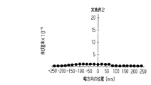
[比較例2]
圧延ローラー51,52の間での押圧力の分布を比較例1から変更し、その他の条件を比較例1の条件と同様に設定することによって、幅方向DWの長さが500mmであり、かつ、厚みが20μmである比較例2の蒸着マスク用基材1を得た。次いで、比較例1と同様に、比較例2の蒸着マスク用基材1から測定用基材2Mを切り出し、切り出された測定用基材2Mの表面距離Lを、測定用基材2Mの幅方向DWの全体にわたり測定して、比較例2の測定用基材2Mでの伸び差率を得た。[Comparative Example 2]
By changing the distribution of the pressing force between the rolling
比較例2の伸び差率の測定結果を図28、および、表1に示す。
図28が示すように、比較例2の中央部RCが有する伸び差率の最大値は、19.66×10⁻⁵であり、各端部REのなかの一方(端部A)の伸び差率は、15×10−5以上であり、上記条件2、および、3を満たさないことが認められた。そして、比較例2では、幅方向DWの両方の端部REのなかの他方(端部B)での伸び差率の最大値が、4.48×10⁻⁵であり、中央部RCでの伸び差率よりも小さく、幅方向DWの両方の端部REのなかの他方(端部A)での伸び差率の最大値が、26.54×10⁻⁵であり、中央部RCでの伸び差率よりも大きいことが認められた。すなわち、上記条件1を満たしていることが認められた。The measurement results of the differential elongation of Comparative Example 2 are shown in FIG.
As shown in FIG. 28, the maximum value of the elongation difference ratio of the central portion RC of the comparative example 2 is 19.66 × 10 −5 , and the elongation difference of one of the end portions RE (end portion A). The rate was 15 × 10 −5 or more, and it was confirmed that the
[比較例3]
圧延ローラー51,52の間での押圧力の分布を比較例1から変更し、その他の条件を比較例1の条件と同様に設定することによって、幅方向DWの長さが500mmであり、かつ、厚みが20μmである比較例3の蒸着マスク用基材1を得た。次いで、比較例1と同様に、比較例3の蒸着マスク用基材1から測定用基材2Mを切り出し、切り出された測定用基材2Mの表面距離Lを、測定用基材2Mの幅方向DWの全体にわたり測定して、比較例3の測定用基材2Mでの伸び差率を得た。[Comparative Example 3]
By changing the distribution of the pressing force between the rolling
比較例3の伸び差率の測定結果を図29、および、表1に示す。
図29が示すように、比較例3の中央部RCが有する伸び差率の最大値は、1.19×10⁻⁵であることが認められた。他方、比較例3の幅方向DWの両方の端部REのなかの一方(端部B)での伸び差率の最大値が、3.24×10⁻⁵であり、中央部RCでの伸び差率よりも大きく、幅方向DWの両方の端部REのなかの他方(端部A)での伸び差率の最大値が、16.10×10⁻⁵であり、中央部RCでの伸び差率よりも大きいことが認められた。すなわち、上記条件2が満たされる一方で、上記条件1,3が満たされないことが認められた。The measurement results of the differential elongation of Comparative Example 3 are shown in FIG.
As FIG. 29 shows, it was recognized that the maximum value of the elongation difference rate which the center part RC of the comparative example 3 has is 1.19 × 10 −5 . On the other hand, the maximum value of the differential elongation at one of the end portions RE in the width direction DW of Comparative Example 3 (end portion B) is 3.24 × 10 −5 , and the elongation at the central portion RC is The maximum value of the elongation difference rate at the other (end portion A) of both end portions RE in the width direction DW is 16.10 × 10 −5 that is larger than the difference rate, and the elongation at the center portion RC. It was observed that it was larger than the difference rate. That is, while the

[パターンの精度]
各実施例1,2,3、および、各比較例1,2,3の蒸着マスク用基材1を用い、蒸着マスク用基材1の第1面1Saに、厚さが10μmの第1ドライフィルムレジスト2を貼り着けた。次いで、第1ドライフィルムレジスト2に露光マスクを接触させて露光する露光工程、および、現像工程を施し、30μmの直径を有した複数の貫通孔2aを、第1ドライフィルムレジスト2に格子状に形成した。続いて、第1ドライフィルムレジスト2をマスクとするエッチングを第1面1Saに施して、格子状に位置する複数の孔32Hを蒸着マスク用基材1に形成した。そして、蒸着マスク用基材1の幅方向DWでの開口径を各孔32Hについて計測した。各孔32Hの幅方向DWでの開口径のばらつきを表1に示す。なお、表1では、各孔32Hが有する開口径のなかで、開口径の最大値と開口径の最小値との差が2.0μm以下である水準に○印を記載し、開口径の最大値と開口径の最小値との差が2.0μmよりも大きい水準に×印を記載した。[Pattern accuracy]
The
表1が示すように、各実施例1,2,3では、開口径のばらつきがいずれも2.0μm以下であることが認められた。他方、各比較例1,2,3では、開口径のばらつきがいずれも2.0μmよりも大きいことが認められた。 As shown in Table 1, in each of Examples 1, 2, and 3, it was recognized that the variation in the aperture diameter was 2.0 μm or less. On the other hand, in each of Comparative Examples 1, 2, and 3, it was recognized that the variation in the aperture diameter was larger than 2.0 μm.
なお、比較例1では、各端部REでの伸び差率が、中央部RCでの伸び差率よりも大きく、また、中央部RCでの伸び差率が9.68×10⁻⁵であって、3×10⁻⁵よりも大きく、条件1,2が満たされていない。そして、比較例1では、条件3が満たされているものの、幅方向DWでの過大な伸び差率に伴う表面での大きな凹凸に起因して、開口径にばらつきが生じてしまうことも認められた。In Comparative Example 1, the differential elongation at each end RE is greater than the differential elongation at the central portion RC, and the differential elongation at the central portion RC is 9.68 × 10 −5. Therefore, it is larger than 3 × 10 −5 and the
また、実施例1,3と比較例2とでは、いずれも、一方の端部REでの伸び差率が、中央部RCでの伸び差率よりも小さく、上記条件1が満たされている。また、これに対して、実施例1,3では、いずれも、中央部RCでの伸び差率が、3.0×10⁻⁵以下である一方、比較例2では、中央部RCの伸び差率が、3.0×10⁻⁵を越え、上記条件2が満たされていない。また、実施例1,2では、両方の端部REでの伸び差率が、15×10−5以下である一方、比較例3では、一方の端部REでの伸び差率が、15×10−5以下を越え、上記条件3が満たされていない。そして、実施例1,2での開口径のばらつきは、2.0μm以下である一方、比較例2での開口径のばらつきは、2.0μmよりも大きい。In each of Examples 1 and 3 and Comparative Example 2, the elongation difference rate at one end RE is smaller than the elongation difference rate at the central portion RC, and the
結果として、これら実施例1,3と比較例2との比較からは、中央部RCでの伸び差率が3×10⁻⁵以下であること、および、各端部REでの伸び差率が15×10−5以下であること、すなわち、条件2,3が満たされることによって、開口径のばらつきが抑えられることが認められた。言い換えれば、一方の端部REでの伸び差率が、中央部RCでの伸び差率よりも小さいことが満たされる蒸着マスク用基材1であっても、上記条件2,3を満たさない構成では、そもそもの過大な伸び差率に伴う大きな凹凸に起因して、開口径にばらつきが生じてしまうことも認められた。As a result, from the comparison between Examples 1 and 3 and Comparative Example 2, the elongation difference rate at the central portion RC is 3 × 10 −5 or less, and the elongation difference rate at each end RE is It was confirmed that the variation in the aperture diameter was suppressed by satisfying the
また、実施例1,3と比較例3とでは、いずれも、中央部RCでの伸び差率は、3×10⁻⁵以下であり、条件2を満たす。これに対して、実施例1,3では、いずれも、一方の端部REでの伸び差率が、中央部RCでの伸び差率よりも小さく、上記条件1が満たされている一方で、比較例3では、各端部REでの伸び差率が、いずれも中央部RCの伸び差率よりも大きく、上記条件1が満たされていない。また、実施例1,2では、両方の端部REでの伸び差率が、15×10−5以下であり、上記条件3が満たされる一方、比較例3では、一方の端部REでの伸び差率が、15×10−5以下を越え、上記条件3が満たされていない。そして、実施例1,2での開口径のばらつきは、2.0μm以下である一方、比較例3での開口径のばらつきは、2.0μmよりも大きい。In each of Examples 1 and 3 and Comparative Example 3, the elongation difference rate at the central portion RC is 3 × 10 −5 or less and satisfies the
結果として、これら実施例1,2と比較例3との比較からは、条件3が満たされないことによって、開口径のばらつきが生じることが認められた。言い換えれば、中央部RCでの伸び差率が、両方の端部REでの伸び差率よりも小さい蒸着マスク用基材1では、一方の端部REでの伸び差率が、他方の端部REでの伸び差率よりも大幅に大きくとも、中央部RCでの液だまりなどに起因して、開口径にばらつきが生じてしまうことも認められた。
As a result, from the comparison between Examples 1 and 2 and Comparative Example 3, it was recognized that variation in the aperture diameter occurred due to the
上記実施形態によれば、以下に列挙する効果が得られる。
(1)マスク部32が備える孔の形状や孔の大きさに関わる精度を高めること、ひいては、蒸着によって形成されるパターンの精度を高めることが可能となる。なお、レジストを露光する方法は、レジストに露光マスクを接触させる方法に限らず、レジストに露光マスクを接触させない露光であってもよい。レジストに露光マスクを接触させる方法であれば、露光マスクの表面に蒸着マスク用基材が押し付けられるため、蒸着マスク用基材が備える波形状に起因した露光精度の低下を抑えられる。いずれの露光方法であっても、液体で表面を加工する工程での精度は高められ、ひいては、蒸着によって形成されるパターンの精度を高めることが可能となる。According to the embodiment, the effects listed below can be obtained.
(1) It is possible to increase the accuracy related to the shape of the hole and the size of the hole provided in the
(2)現像液による現像の結果や、その洗浄液による洗浄の結果について、蒸着マスク用基材1の表面でのばらつきを抑えられる。結果として、露光工程と、現像工程とを経て形成される第1貫通孔2aや第2貫通孔3aについて、その形状や大きさの均一性を、蒸着マスク用基材1の表面内で高めることが可能となる。
(2) Variations on the surface of the vapor
(3)エッチング液によるエッチングの結果や、その洗浄液によるエッチング液の洗浄の結果について、蒸着マスク用基材1の表面でのばらつきを抑えられる。また、剥離液によるレジスト層の剥離の結果や、その洗浄液による剥離液の洗浄の結果について、蒸着マスク用基材1の表面でのばらつきを抑えられる。結果として、小孔32SHの形状や大きさ、また、大孔32LHの形状や大きさに関して、蒸着マスク用基材1の表面内での均一性を高めることが可能となる。
(3) About the result of the etching with the etching solution and the result of the cleaning with the cleaning solution, the variation on the surface of the vapor
(4)1つのフレーム部31に必要とされる孔32Hの総数量を、例えば、3つのマスク部32で担う。すなわち、1つのフレーム部31に必要とされるマスク部32の総面積を、例えば、3つのマスク部32に分割している。そのため、1つのフレーム部31においてマスク部32の一部に変形が生じた場合であっても、1つのフレーム部31の全てのマスク部32を交換する必要はない。そして、変形したマスク部32と交換される新たなマスク部32の大きさを、1つのフレーム部31に1つのマスク部32を備える構成と比べて、1/3程度に小さくすることが可能ともなる。
(4) The total number of
(5)測定用基材2Mを用いた表面距離Lの測定では、測定用基材2Mの長手方向DLでの両方の端部を、非計測範囲ZEとして、表面距離Lの測定対象から除外している。各非計測範囲ZEは、蒸着マスク用基材1の切断によって、蒸着マスク用基材1とは異なる波形状を有する可能性を有した範囲である。そのため、非計測範囲ZEを測定対象から除外する測定であれば、表面距離Lの精度を高めることが可能である。
(5) In the measurement of the surface distance L using the
C…コア、F…応力、L…表面距離、S…蒸着対象、V…空間、W…寸法、CP…クランプ、DL…長手方向、DW…幅方向、EP…電極、H1…第1開口、H2…第2開口、Lm…最小表面距離、PC…中心、PR…レジスト層、RC…中央部、RE…端部、RM…レジストマスク、SH…ステップハイト、SP…支持体、TM…中間転写基材、ZE…非計測範囲、ZL…計測範囲、EPS…電極表面、1…蒸着マスク用基材、1a…母材、1b…圧延材、1Sa,321…第1面、1Sb,322…第2面、2…測定用基材、2a…第1貫通孔、2S…表面、3a…第2貫通孔、4…第1保護層、10…マスク装置、20…メインフレーム、21…メインフレーム孔、30…蒸着マスク、31…フレーム部、31E…内縁部、32,32A,32B,32C…マスク部、32BN…接合部、32E…外縁部、32H…孔、32K…基材、32LH…大孔、32SH…小孔、33,33A,33B,33C…フレーム孔、50…圧延装置、51,52…圧延ローラー、53…アニール装置、61…第2保護層、311…接合面、312…非接合面、323…マスク板。
C ... Core, F ... Stress, L ... Surface distance, S ... Deposition target, V ... Space, W ... Dimensions, CP ... Clamp, DL ... Longitudinal direction, DW ... Width direction, EP ... Electrode, H1 ... First opening, H2 ... second opening, Lm ... minimum surface distance, PC ... center, PR ... resist layer, RC ... center, RE ... edge, RM ... resist mask, SH ... step height, SP ... support, TM ... intermediate transfer Base material, ZE ... non-measurement range, ZL ... measurement range, EPS ... electrode surface, 1 ... substrate for vapor deposition mask, 1a ... base material, 1b ... rolled material, 1Sa, 321 ... first surface, 1Sb, 322 ... first Two surfaces, 2 ... base material for measurement, 2a ... first through hole, 2S ... surface, 3a ... second through hole, 4 ... first protective layer, 10 ... mask device, 20 ... main frame, 21 ...
Claims (6)
前記金属板の幅方向での各位置における前記金属板の長手方向に沿った形状は相互に異なっており、各形状は前記金属板の長手方向に繰り返す凹凸を有する波形状であり、
前記金属板の表面での長手方向の長さが表面距離であり、
前記金属板の幅方向の各位置での表面距離のなかの最小値が最小表面距離であり、
前記最小表面距離に対する前記金属板の幅方向の各位置での表面距離と前記最小表面距離との差分の比率が伸び差率であり、
前記金属板の幅方向での中央部の伸び差率が、3×10⁻⁵以下であり、
前記金属板の幅方向での両方の端部の伸び差率が、15×10−5以下であり、
前記金属板の幅方向での両方の端部のなかの少なくとも一方での伸び差率は、前記金属板の幅方向の中央部の伸び差率よりも小さい、
蒸着マスク用基材。A substrate for a deposition mask, which is a metal plate having a strip shape, used for manufacturing a deposition mask by forming a plurality of holes by etching,
The shape along the longitudinal direction of the metal plate at each position in the width direction of the metal plate is different from each other, each shape is a wave shape having irregularities repeated in the longitudinal direction of the metal plate,
The length in the longitudinal direction on the surface of the metal plate is the surface distance,
The minimum value of the surface distance at each position in the width direction of the metal plate is the minimum surface distance,
The ratio of the difference between the surface distance at each position in the width direction of the metal plate relative to the minimum surface distance and the minimum surface distance is an elongation difference rate,
The elongation difference of the central part in the width direction of the metal plate is 3 × 10 −5 or less,
The elongation difference rate of both ends in the width direction of the metal plate is 15 × 10 −5 or less,
The elongation difference rate of at least one of both end portions in the width direction of the metal plate is smaller than the elongation difference rate of the center portion in the width direction of the metal plate,
Deposition mask substrate.
前記両方の端部での伸び差率の最大値の差は、3×10⁻⁵以上11×10−5以下である
請求項1に記載の蒸着マスク用基材。Only the elongation difference rate in one of both end portions in the width direction of the metal plate is smaller than the elongation difference rate in the center portion in the width direction of the metal plate,
Difference between the maximum value of the differential expansion rates in the both ends, 3 × 10 -5 or more 11 × 10 -5 or less deposition mask substrate according to claim 1.
前記両方の端部での伸び差率、および、前記中央部での伸び差率が、1×10⁻⁵以下である
請求項1に記載の蒸着マスク用基材。The elongation difference rate at both ends in the width direction of the metal plate is smaller than the elongation difference rate at the center portion in the width direction of the metal plate,
The base material for vapor deposition masks of Claim 1. The elongation difference rate in the said both edge parts and the elongation difference rate in the said center part are 1x10 <-5> or less.
母材を圧延して前記金属板を得ることを含み、
前記金属板の幅方向での各位置における前記金属板の長手方向に沿った形状は相互に異なっており、各形状は前記金属板の長手方向に繰り返す凹凸を有する波形状であり、
前記金属板の表面での長手方向の長さが表面距離であり、
前記金属板の幅方向の各位置での表面距離のなかの最小値が最小表面距離であり、
前記最小表面距離に対する前記金属板の幅方向の各位置での表面距離と前記最小表面距離との差分の比率が伸び差率であり、
前記金属板を得ることでは、
前記金属板の幅方向での中央部の伸び差率が3×10⁻⁵以下であり、
前記金属板の幅方向での両方の端部の伸び差率が15×10−5以下であり、
前記金属板の幅方向での両方の端部のなかの少なくとも一方での伸び差率が、前記金属板の幅方向の中央部の伸び差率よりも小さくなるように、前記母材を圧延する、
蒸着マスク用基材の製造方法。A method for producing a substrate for a vapor deposition mask, which is a metal plate having a band shape, which is used for producing a vapor deposition mask by forming a plurality of holes by etching,
Rolling the base material to obtain the metal plate,
The shape along the longitudinal direction of the metal plate at each position in the width direction of the metal plate is different from each other, each shape is a wave shape having irregularities repeated in the longitudinal direction of the metal plate,
The length in the longitudinal direction on the surface of the metal plate is the surface distance,
The minimum value of the surface distance at each position in the width direction of the metal plate is the minimum surface distance,
The ratio of the difference between the surface distance at each position in the width direction of the metal plate relative to the minimum surface distance and the minimum surface distance is an elongation difference rate,
In obtaining the metal plate,
The elongation difference of the central part in the width direction of the metal plate is 3 × 10 −5 or less,
The elongation difference of both ends in the width direction of the metal plate is 15 × 10 −5 or less,
The base material is rolled so that the elongation difference rate of at least one of both end portions in the width direction of the metal plate is smaller than the elongation difference rate of the center portion in the width direction of the metal plate. ,
A method for producing a substrate for a vapor deposition mask.
前記レジスト層をマスクとしたエッチングによって前記金属板に複数の孔を形成してマスク部を形成することと、を含む蒸着マスクの製造方法であって、
前記金属板の幅方向での各位置における前記金属板の長手方向に沿った形状は相互に異なっており、各形状は前記金属板の長手方向に繰り返す凹凸を有する波形状であり、
前記金属板の表面での長手方向の長さが表面距離であり、
前記金属板の幅方向の各位置での表面距離のなかの最小値が最小表面距離であり、
前記最小表面距離に対する前記金属板の幅方向の各位置での表面距離と前記最小表面距離との差分の比率が伸び差率であり、
前記金属板を得ることでは、
前記金属板の幅方向での中央部の伸び差率が3×10⁻⁵以下であり、
前記金属板の幅方向での両方の端部の伸び差率が15×10−5以下であり、
前記金属板の幅方向での両方の端部のなかの少なくとも一方での伸び差率が、前記金属板の幅方向の中央部の伸び差率よりも小さい、
蒸着マスクの製造方法。Forming a resist layer on a metal plate having a strip shape;
Forming a plurality of holes in the metal plate by etching using the resist layer as a mask to form a mask portion,
The shape along the longitudinal direction of the metal plate at each position in the width direction of the metal plate is different from each other, each shape is a wave shape having irregularities repeated in the longitudinal direction of the metal plate,
The length in the longitudinal direction on the surface of the metal plate is the surface distance,
The minimum value of the surface distance at each position in the width direction of the metal plate is the minimum surface distance,
The ratio of the difference between the surface distance at each position in the width direction of the metal plate relative to the minimum surface distance and the minimum surface distance is an elongation difference rate,
In obtaining the metal plate,
The elongation difference of the central part in the width direction of the metal plate is 3 × 10 −5 or less,
The elongation difference of both ends in the width direction of the metal plate is 15 × 10 −5 or less,
The elongation difference rate of at least one of both end portions in the width direction of the metal plate is smaller than the elongation difference rate of the center portion in the width direction of the metal plate,
A method for manufacturing a vapor deposition mask.
請求項5に記載の蒸着マスクの製造方法。For each of the plurality of mask portions, each of the mask portions has one side surface that each of the mask portions separately includes and the side surface in which the opening of the hole is formed, and the single frame portion. The method for manufacturing a vapor deposition mask according to claim 5, further comprising joining a plurality of holes so that the single frame portion surrounds the holes.
Priority Applications (1)
| Application Number | Priority Date | Filing Date | Title |
|---|---|---|---|
| JP2017212942A JP6939431B2 (en) | 2016-04-14 | 2017-11-02 | A base material for a vapor deposition mask, a method for manufacturing a base material for a vapor deposition mask, and a method for manufacturing a vapor deposition mask. |
Applications Claiming Priority (3)
| Application Number | Priority Date | Filing Date | Title |
|---|---|---|---|
| JP2016081362 | 2016-04-14 | ||
| JP2016081362 | 2016-04-14 | ||
| PCT/JP2017/015357 WO2017179719A1 (en) | 2016-04-14 | 2017-04-14 | Vapor deposition mask base material, vapor deposition mask base material manufacturing method, and vapor deposition mask manufacturing method |
Related Child Applications (1)
| Application Number | Title | Priority Date | Filing Date |
|---|---|---|---|
| JP2017212942A Division JP6939431B2 (en) | 2016-04-14 | 2017-11-02 | A base material for a vapor deposition mask, a method for manufacturing a base material for a vapor deposition mask, and a method for manufacturing a vapor deposition mask. |
Publications (2)
| Publication Number | Publication Date |
|---|---|
| JP6237972B1 true JP6237972B1 (en) | 2017-11-29 |
| JPWO2017179719A1 JPWO2017179719A1 (en) | 2018-04-19 |
Family
ID=60041847
Family Applications (2)
| Application Number | Title | Priority Date | Filing Date |
|---|---|---|---|
| JP2017541417A Active JP6237972B1 (en) | 2016-04-14 | 2017-04-14 | Vapor deposition mask substrate, vapor deposition mask substrate production method, and vapor deposition mask production method |
| JP2017212942A Active JP6939431B2 (en) | 2016-04-14 | 2017-11-02 | A base material for a vapor deposition mask, a method for manufacturing a base material for a vapor deposition mask, and a method for manufacturing a vapor deposition mask. |
Family Applications After (1)
| Application Number | Title | Priority Date | Filing Date |
|---|---|---|---|
| JP2017212942A Active JP6939431B2 (en) | 2016-04-14 | 2017-11-02 | A base material for a vapor deposition mask, a method for manufacturing a base material for a vapor deposition mask, and a method for manufacturing a vapor deposition mask. |
Country Status (7)
| Country | Link |
|---|---|
| US (2) | US10767266B2 (en) |
| JP (2) | JP6237972B1 (en) |
| KR (2) | KR102115724B1 (en) |
| CN (2) | CN110144547B (en) |
| DE (1) | DE112017002022B4 (en) |
| TW (2) | TWI713899B (en) |
| WO (1) | WO2017179719A1 (en) |
Cited By (1)
| Publication number | Priority date | Publication date | Assignee | Title |
|---|---|---|---|---|
| US11499235B2 (en) | 2017-10-13 | 2022-11-15 | Toppan Printing Co., Ltd. | Vapor deposition mask substrate, vapor deposition mask substrate manufacturing method, vapor deposition mask manufacturing method, and display device manufacturing method |
Families Citing this family (17)
| Publication number | Priority date | Publication date | Assignee | Title |
|---|---|---|---|---|
| KR102115724B1 (en) | 2016-04-14 | 2020-05-27 | 도판 인사츠 가부시키가이샤 | Vapor deposition mask base material, vapor deposition mask base material manufacturing method, and vapor deposition mask manufacturing method |
| DE102016122198A1 (en) * | 2016-11-18 | 2018-05-24 | Wickeder Westfalenstahl Gmbh | Method for producing a composite material, and composite material |
| JP6319505B1 (en) | 2017-09-08 | 2018-05-09 | 凸版印刷株式会社 | Vapor deposition mask substrate, vapor deposition mask substrate production method, vapor deposition mask production method, and display device production method |
| JP6984529B2 (en) * | 2017-09-08 | 2021-12-22 | 凸版印刷株式会社 | A base material for a vapor deposition mask, a method for manufacturing a base material for a vapor deposition mask, a method for manufacturing a vapor deposition mask, and a method for manufacturing a display device. |
| KR102153870B1 (en) * | 2017-09-15 | 2020-09-09 | 도판 인사츠 가부시키가이샤 | Deposition mask manufacturing method, display device manufacturing method, and evaporation mask |
| JP6981302B2 (en) * | 2017-10-13 | 2021-12-15 | 凸版印刷株式会社 | A base material for a vapor deposition mask, a method for manufacturing a base material for a vapor deposition mask, a method for manufacturing a vapor deposition mask, and a method for manufacturing a display device. |
| JP6988565B2 (en) * | 2017-10-13 | 2022-01-05 | 凸版印刷株式会社 | A base material for a vapor deposition mask, a method for manufacturing a base material for a vapor deposition mask, a method for manufacturing a vapor deposition mask, and a method for manufacturing a display device. |
| JP6299922B1 (en) * | 2017-10-13 | 2018-03-28 | 凸版印刷株式会社 | Vapor deposition mask substrate, vapor deposition mask substrate production method, vapor deposition mask production method, and display device production method |
| KR20190055910A (en) * | 2017-11-16 | 2019-05-24 | 엘지이노텍 주식회사 | A deposition mask and method for manufacturing of the same |
| JP6597920B1 (en) * | 2018-04-11 | 2019-10-30 | 凸版印刷株式会社 | Vapor deposition mask substrate, vapor deposition mask substrate production method, vapor deposition mask production method, and display device production method |
| TWI782212B (en) * | 2018-06-08 | 2022-11-01 | 日商大日本印刷股份有限公司 | Winding body of metal plate, packing body provided with winding body, packaging method of winding body, storage method of winding body, manufacturing method of vapor deposition cover using metal plate of winding body, and metal plate |
| WO2020012862A1 (en) * | 2018-07-09 | 2020-01-16 | 大日本印刷株式会社 | Vapor-deposition mask defective determination method, vapor-deposition mask manufacturing method, vapor deposition mask device manufacturing method, vapor-deposition mask selection method, and vapor-deposition mask |
| KR102188948B1 (en) * | 2019-02-12 | 2020-12-09 | 주식회사 오럼머티리얼 | Producing method of mask integrated frame |
| KR20200074341A (en) * | 2018-12-14 | 2020-06-25 | 삼성디스플레이 주식회사 | Metal mask, method of manufacturing the same, and method of manufacturing display panel |
| JP7449485B2 (en) * | 2019-03-28 | 2024-03-14 | 大日本印刷株式会社 | Vapor deposition mask and method for manufacturing a vapor deposition mask |
| JP2021042439A (en) * | 2019-09-11 | 2021-03-18 | 株式会社ジャパンディスプレイ | Vapor deposition mask and production method of vapor deposition mask |
| KR102501481B1 (en) | 2022-07-12 | 2023-02-21 | (주)세우인코퍼레이션 | Method for manufacturing fine metal mask for deposition of ultra high definition class |
Citations (4)
| Publication number | Priority date | Publication date | Assignee | Title |
|---|---|---|---|---|
| JP2005028407A (en) * | 2003-07-14 | 2005-02-03 | Jfe Steel Kk | Method for controlling shape of rolled stock |
| JP2014008520A (en) * | 2012-06-29 | 2014-01-20 | Nippon Steel & Sumitomo Metal | Cold rolling method of metal plate and method of manufacturing metal plate |
| JP2014148743A (en) * | 2013-01-10 | 2014-08-21 | Dainippon Printing Co Ltd | Metal plate, production method of metal plate, and production method of vapor deposition mask by using metal plate |
| JP2015055007A (en) * | 2013-09-13 | 2015-03-23 | 大日本印刷株式会社 | Metal plate, manufacturing method of metal plate, and manufacturing method of mask using metal plate |
Family Cites Families (34)
| Publication number | Priority date | Publication date | Assignee | Title |
|---|---|---|---|---|
| JPS5839377A (en) | 1981-09-02 | 1983-03-08 | Toshiba Corp | Character recognizing device |
| JPH05290724A (en) | 1992-04-10 | 1993-11-05 | Toshiba Corp | Manufacture of shadow mask |
| JP3487471B2 (en) | 1996-01-30 | 2004-01-19 | 日立金属株式会社 | Fe-Ni alloy thin plate with excellent etching processability |
| JPH11140667A (en) | 1997-11-13 | 1999-05-25 | Dainippon Printing Co Ltd | Base material for etching, etching method and etched product |
| JPH11229040A (en) | 1998-02-16 | 1999-08-24 | Nkk Corp | Annealing method and apparatus correcting shape of fe-ni alloy steel strip |
| KR100534580B1 (en) | 2003-03-27 | 2005-12-07 | 삼성에스디아이 주식회사 | Deposition mask for display device and Method for fabricating the same |
| JP4341382B2 (en) | 2003-11-21 | 2009-10-07 | 凸版印刷株式会社 | Manufacturing method of vapor deposition mask |
| TW200622491A (en) * | 2004-09-28 | 2006-07-01 | Fuji Photo Film Co Ltd | Pattern-forming material, pattern-forming device and pattern-forming method |
| KR100708654B1 (en) | 2004-11-18 | 2007-04-18 | 삼성에스디아이 주식회사 | Mask assembly and mask frame assembly using the same |
| JP4609187B2 (en) | 2005-05-30 | 2011-01-12 | 凸版印刷株式会社 | Manufacturing method of multi-faced metal mask |
| KR101433899B1 (en) * | 2008-04-03 | 2014-08-29 | 삼성전자주식회사 | Method for forming metallic layer on portion etched of substrate, the substrate having the metallic layer formed using the same and a structure formed using the same |
| JP2009299170A (en) | 2008-06-17 | 2009-12-24 | Toppan Printing Co Ltd | Method for manufacturing etching component |
| JP5294072B2 (en) | 2009-03-18 | 2013-09-18 | 日立金属株式会社 | Etching material manufacturing method and etching material |
| JP2013055039A (en) | 2011-08-11 | 2013-03-21 | Canon Inc | Manufacturing method of el light-emitting device and vapor deposition device |
| JP5288073B2 (en) | 2012-01-12 | 2013-09-11 | 大日本印刷株式会社 | Method for manufacturing vapor deposition mask and method for manufacturing organic semiconductor element |
| JP2014088594A (en) * | 2012-10-30 | 2014-05-15 | V Technology Co Ltd | Vapor deposition mask |
| JP5382257B1 (en) * | 2013-01-10 | 2014-01-08 | 大日本印刷株式会社 | Metal plate, method for producing metal plate, and method for producing vapor deposition mask using metal plate |
| JP5516816B1 (en) | 2013-10-15 | 2014-06-11 | 大日本印刷株式会社 | Metal plate, method for producing metal plate, and method for producing vapor deposition mask using metal plate |
| KR101885053B1 (en) | 2013-12-06 | 2018-08-02 | 코니카 미놀타 가부시키가이샤 | Organic electroluminescence element |
| JP2015129334A (en) | 2014-01-08 | 2015-07-16 | 大日本印刷株式会社 | Method of manufacturing laminate mask, laminate mask, and laminate mask with protective film |
| JP2015193871A (en) | 2014-03-31 | 2015-11-05 | 日立金属株式会社 | Fe-Ni-BASED ALLOY THIN SHEET AND MANUFACTURING METHOD THEREFOR |
| JP6511908B2 (en) | 2014-03-31 | 2019-05-15 | 大日本印刷株式会社 | Tension method of deposition mask, method of manufacturing deposition mask with frame, method of manufacturing organic semiconductor device, and tension device |
| JP6354358B2 (en) | 2014-06-11 | 2018-07-11 | 凸版印刷株式会社 | Metal mask transfer jig and metal mask inspection method |
| CN205974646U (en) | 2015-07-17 | 2017-02-22 | 凸版印刷株式会社 | Metal mask for coating by vaporization |
| JP2017064764A (en) | 2015-09-30 | 2017-04-06 | 日立金属株式会社 | Fe-Ni-BASED ALLOY THIN SHEET AND PRODUCTION METHOD OF THE SAME |
| JP6598007B2 (en) | 2015-09-30 | 2019-10-30 | 日立金属株式会社 | Method for producing Fe-Ni alloy thin sheet |
| JP6631173B2 (en) | 2015-11-05 | 2020-01-15 | 凸版印刷株式会社 | Evaporation mask, mask base repair method, and mask base repair apparatus |
| US11098393B2 (en) | 2016-03-09 | 2021-08-24 | Hitachi Metals, Ltd. | Martensitic stainless steel foil and manufacturing method thereof |
| JP6852270B2 (en) | 2016-03-31 | 2021-03-31 | 凸版印刷株式会社 | Manufacturing method of metal processed plate |
| JP6759666B2 (en) | 2016-03-31 | 2020-09-23 | 凸版印刷株式会社 | Method for manufacturing photosensitive composition for etching protection and metal processed plate |
| KR102115724B1 (en) | 2016-04-14 | 2020-05-27 | 도판 인사츠 가부시키가이샤 | Vapor deposition mask base material, vapor deposition mask base material manufacturing method, and vapor deposition mask manufacturing method |
| JP6319505B1 (en) | 2017-09-08 | 2018-05-09 | 凸版印刷株式会社 | Vapor deposition mask substrate, vapor deposition mask substrate production method, vapor deposition mask production method, and display device production method |
| JP6299921B1 (en) | 2017-10-13 | 2018-03-28 | 凸版印刷株式会社 | Vapor deposition mask substrate, vapor deposition mask substrate production method, vapor deposition mask production method, and display device production method |
| JP6299922B1 (en) | 2017-10-13 | 2018-03-28 | 凸版印刷株式会社 | Vapor deposition mask substrate, vapor deposition mask substrate production method, vapor deposition mask production method, and display device production method |
-
2017
- 2017-04-14 KR KR1020187036307A patent/KR102115724B1/en active IP Right Grant
- 2017-04-14 KR KR1020177037898A patent/KR101931902B1/en active IP Right Grant
- 2017-04-14 JP JP2017541417A patent/JP6237972B1/en active Active
- 2017-04-14 CN CN201910237719.XA patent/CN110144547B/en active Active
- 2017-04-14 TW TW107133208A patent/TWI713899B/en active
- 2017-04-14 WO PCT/JP2017/015357 patent/WO2017179719A1/en active Application Filing
- 2017-04-14 TW TW106112472A patent/TWI639720B/en active
- 2017-04-14 DE DE112017002022.0T patent/DE112017002022B4/en active Active
- 2017-04-14 CN CN201780002450.6A patent/CN107849682B/en active Active
- 2017-11-02 JP JP2017212942A patent/JP6939431B2/en active Active
-
2018
- 2018-07-02 US US16/025,857 patent/US10767266B2/en active Active
-
2020
- 2020-08-05 US US16/985,229 patent/US11390953B2/en active Active
Patent Citations (4)
| Publication number | Priority date | Publication date | Assignee | Title |
|---|---|---|---|---|
| JP2005028407A (en) * | 2003-07-14 | 2005-02-03 | Jfe Steel Kk | Method for controlling shape of rolled stock |
| JP2014008520A (en) * | 2012-06-29 | 2014-01-20 | Nippon Steel & Sumitomo Metal | Cold rolling method of metal plate and method of manufacturing metal plate |
| JP2014148743A (en) * | 2013-01-10 | 2014-08-21 | Dainippon Printing Co Ltd | Metal plate, production method of metal plate, and production method of vapor deposition mask by using metal plate |
| JP2015055007A (en) * | 2013-09-13 | 2015-03-23 | 大日本印刷株式会社 | Metal plate, manufacturing method of metal plate, and manufacturing method of mask using metal plate |
Cited By (1)
| Publication number | Priority date | Publication date | Assignee | Title |
|---|---|---|---|---|
| US11499235B2 (en) | 2017-10-13 | 2022-11-15 | Toppan Printing Co., Ltd. | Vapor deposition mask substrate, vapor deposition mask substrate manufacturing method, vapor deposition mask manufacturing method, and display device manufacturing method |
Also Published As
| Publication number | Publication date |
|---|---|
| KR101931902B1 (en) | 2018-12-21 |
| KR20180136576A (en) | 2018-12-24 |
| TW201742935A (en) | 2017-12-16 |
| CN107849682A (en) | 2018-03-27 |
| KR20180005718A (en) | 2018-01-16 |
| KR102115724B1 (en) | 2020-05-27 |
| JPWO2017179719A1 (en) | 2018-04-19 |
| CN110144547A (en) | 2019-08-20 |
| WO2017179719A1 (en) | 2017-10-19 |
| US10767266B2 (en) | 2020-09-08 |
| CN110144547B (en) | 2021-06-01 |
| JP6939431B2 (en) | 2021-09-22 |
| US11390953B2 (en) | 2022-07-19 |
| US20180312979A1 (en) | 2018-11-01 |
| CN107849682B (en) | 2019-04-19 |
| JP2018024946A (en) | 2018-02-15 |
| US20200362465A1 (en) | 2020-11-19 |
| TW201900910A (en) | 2019-01-01 |
| DE112017002022B4 (en) | 2023-06-01 |
| TWI639720B (en) | 2018-11-01 |
| TWI713899B (en) | 2020-12-21 |
| DE112017002022T5 (en) | 2019-01-24 |
Similar Documents
| Publication | Publication Date | Title |
|---|---|---|
| JP6237972B1 (en) | Vapor deposition mask substrate, vapor deposition mask substrate production method, and vapor deposition mask production method | |
| JP6299921B1 (en) | Vapor deposition mask substrate, vapor deposition mask substrate production method, vapor deposition mask production method, and display device production method | |
| JP6299922B1 (en) | Vapor deposition mask substrate, vapor deposition mask substrate production method, vapor deposition mask production method, and display device production method | |
| JP6319505B1 (en) | Vapor deposition mask substrate, vapor deposition mask substrate production method, vapor deposition mask production method, and display device production method | |
| JP6988565B2 (en) | A base material for a vapor deposition mask, a method for manufacturing a base material for a vapor deposition mask, a method for manufacturing a vapor deposition mask, and a method for manufacturing a display device. | |
| JP6981302B2 (en) | A base material for a vapor deposition mask, a method for manufacturing a base material for a vapor deposition mask, a method for manufacturing a vapor deposition mask, and a method for manufacturing a display device. | |
| JP6984529B2 (en) | A base material for a vapor deposition mask, a method for manufacturing a base material for a vapor deposition mask, a method for manufacturing a vapor deposition mask, and a method for manufacturing a display device. |
Legal Events
| Date | Code | Title | Description |
|---|---|---|---|
| A975 | Report on accelerated examination |
Free format text: JAPANESE INTERMEDIATE CODE: A971005 Effective date: 20170901 |
|
| TRDD | Decision of grant or rejection written | ||
| A01 | Written decision to grant a patent or to grant a registration (utility model) |
Free format text: JAPANESE INTERMEDIATE CODE: A01 Effective date: 20171003 |
|
| A61 | First payment of annual fees (during grant procedure) |
Free format text: JAPANESE INTERMEDIATE CODE: A61 Effective date: 20171016 |
|
| R150 | Certificate of patent or registration of utility model |
Ref document number: 6237972 Country of ref document: JP Free format text: JAPANESE INTERMEDIATE CODE: R150 |
|
| R250 | Receipt of annual fees |
Free format text: JAPANESE INTERMEDIATE CODE: R250 |
|
| R250 | Receipt of annual fees |
Free format text: JAPANESE INTERMEDIATE CODE: R250 |
|
| R250 | Receipt of annual fees |
Free format text: JAPANESE INTERMEDIATE CODE: R250 |
|
| R250 | Receipt of annual fees |
Free format text: JAPANESE INTERMEDIATE CODE: R250 |