JP6237425B2 - vehicle - Google Patents
vehicle Download PDFInfo
- Publication number
- JP6237425B2 JP6237425B2 JP2014080610A JP2014080610A JP6237425B2 JP 6237425 B2 JP6237425 B2 JP 6237425B2 JP 2014080610 A JP2014080610 A JP 2014080610A JP 2014080610 A JP2014080610 A JP 2014080610A JP 6237425 B2 JP6237425 B2 JP 6237425B2
- Authority
- JP
- Japan
- Prior art keywords
- value
- power
- battery
- assembled battery
- vehicle
- Prior art date
- Legal status (The legal status is an assumption and is not a legal conclusion. Google has not performed a legal analysis and makes no representation as to the accuracy of the status listed.)
- Active
Links
Images


Classifications
-
- B—PERFORMING OPERATIONS; TRANSPORTING
- B60—VEHICLES IN GENERAL
- B60L—PROPULSION OF ELECTRICALLY-PROPELLED VEHICLES; SUPPLYING ELECTRIC POWER FOR AUXILIARY EQUIPMENT OF ELECTRICALLY-PROPELLED VEHICLES; ELECTRODYNAMIC BRAKE SYSTEMS FOR VEHICLES IN GENERAL; MAGNETIC SUSPENSION OR LEVITATION FOR VEHICLES; MONITORING OPERATING VARIABLES OF ELECTRICALLY-PROPELLED VEHICLES; ELECTRIC SAFETY DEVICES FOR ELECTRICALLY-PROPELLED VEHICLES
- B60L58/00—Methods or circuit arrangements for monitoring or controlling batteries or fuel cells, specially adapted for electric vehicles
- B60L58/10—Methods or circuit arrangements for monitoring or controlling batteries or fuel cells, specially adapted for electric vehicles for monitoring or controlling batteries
- B60L58/12—Methods or circuit arrangements for monitoring or controlling batteries or fuel cells, specially adapted for electric vehicles for monitoring or controlling batteries responding to state of charge [SoC]
- B60L58/14—Preventing excessive discharging
-
- H—ELECTRICITY
- H02—GENERATION; CONVERSION OR DISTRIBUTION OF ELECTRIC POWER
- H02J—CIRCUIT ARRANGEMENTS OR SYSTEMS FOR SUPPLYING OR DISTRIBUTING ELECTRIC POWER; SYSTEMS FOR STORING ELECTRIC ENERGY
- H02J7/00—Circuit arrangements for charging or depolarising batteries or for supplying loads from batteries
-
- B—PERFORMING OPERATIONS; TRANSPORTING
- B60—VEHICLES IN GENERAL
- B60K—ARRANGEMENT OR MOUNTING OF PROPULSION UNITS OR OF TRANSMISSIONS IN VEHICLES; ARRANGEMENT OR MOUNTING OF PLURAL DIVERSE PRIME-MOVERS IN VEHICLES; AUXILIARY DRIVES FOR VEHICLES; INSTRUMENTATION OR DASHBOARDS FOR VEHICLES; ARRANGEMENTS IN CONNECTION WITH COOLING, AIR INTAKE, GAS EXHAUST OR FUEL SUPPLY OF PROPULSION UNITS IN VEHICLES
- B60K6/00—Arrangement or mounting of plural diverse prime-movers for mutual or common propulsion, e.g. hybrid propulsion systems comprising electric motors and internal combustion engines ; Control systems therefor, i.e. systems controlling two or more prime movers, or controlling one of these prime movers and any of the transmission, drive or drive units Informative references: mechanical gearings with secondary electric drive F16H3/72; arrangements for handling mechanical energy structurally associated with the dynamo-electric machine H02K7/00; machines comprising structurally interrelated motor and generator parts H02K51/00; dynamo-electric machines not otherwise provided for in H02K see H02K99/00
- B60K6/20—Arrangement or mounting of plural diverse prime-movers for mutual or common propulsion, e.g. hybrid propulsion systems comprising electric motors and internal combustion engines ; Control systems therefor, i.e. systems controlling two or more prime movers, or controlling one of these prime movers and any of the transmission, drive or drive units Informative references: mechanical gearings with secondary electric drive F16H3/72; arrangements for handling mechanical energy structurally associated with the dynamo-electric machine H02K7/00; machines comprising structurally interrelated motor and generator parts H02K51/00; dynamo-electric machines not otherwise provided for in H02K see H02K99/00 the prime-movers consisting of electric motors and internal combustion engines, e.g. HEVs
- B60K6/22—Arrangement or mounting of plural diverse prime-movers for mutual or common propulsion, e.g. hybrid propulsion systems comprising electric motors and internal combustion engines ; Control systems therefor, i.e. systems controlling two or more prime movers, or controlling one of these prime movers and any of the transmission, drive or drive units Informative references: mechanical gearings with secondary electric drive F16H3/72; arrangements for handling mechanical energy structurally associated with the dynamo-electric machine H02K7/00; machines comprising structurally interrelated motor and generator parts H02K51/00; dynamo-electric machines not otherwise provided for in H02K see H02K99/00 the prime-movers consisting of electric motors and internal combustion engines, e.g. HEVs characterised by apparatus, components or means specially adapted for HEVs
- B60K6/28—Arrangement or mounting of plural diverse prime-movers for mutual or common propulsion, e.g. hybrid propulsion systems comprising electric motors and internal combustion engines ; Control systems therefor, i.e. systems controlling two or more prime movers, or controlling one of these prime movers and any of the transmission, drive or drive units Informative references: mechanical gearings with secondary electric drive F16H3/72; arrangements for handling mechanical energy structurally associated with the dynamo-electric machine H02K7/00; machines comprising structurally interrelated motor and generator parts H02K51/00; dynamo-electric machines not otherwise provided for in H02K see H02K99/00 the prime-movers consisting of electric motors and internal combustion engines, e.g. HEVs characterised by apparatus, components or means specially adapted for HEVs characterised by the electric energy storing means, e.g. batteries or capacitors
-
- B—PERFORMING OPERATIONS; TRANSPORTING
- B60—VEHICLES IN GENERAL
- B60K—ARRANGEMENT OR MOUNTING OF PROPULSION UNITS OR OF TRANSMISSIONS IN VEHICLES; ARRANGEMENT OR MOUNTING OF PLURAL DIVERSE PRIME-MOVERS IN VEHICLES; AUXILIARY DRIVES FOR VEHICLES; INSTRUMENTATION OR DASHBOARDS FOR VEHICLES; ARRANGEMENTS IN CONNECTION WITH COOLING, AIR INTAKE, GAS EXHAUST OR FUEL SUPPLY OF PROPULSION UNITS IN VEHICLES
- B60K6/00—Arrangement or mounting of plural diverse prime-movers for mutual or common propulsion, e.g. hybrid propulsion systems comprising electric motors and internal combustion engines ; Control systems therefor, i.e. systems controlling two or more prime movers, or controlling one of these prime movers and any of the transmission, drive or drive units Informative references: mechanical gearings with secondary electric drive F16H3/72; arrangements for handling mechanical energy structurally associated with the dynamo-electric machine H02K7/00; machines comprising structurally interrelated motor and generator parts H02K51/00; dynamo-electric machines not otherwise provided for in H02K see H02K99/00
- B60K6/20—Arrangement or mounting of plural diverse prime-movers for mutual or common propulsion, e.g. hybrid propulsion systems comprising electric motors and internal combustion engines ; Control systems therefor, i.e. systems controlling two or more prime movers, or controlling one of these prime movers and any of the transmission, drive or drive units Informative references: mechanical gearings with secondary electric drive F16H3/72; arrangements for handling mechanical energy structurally associated with the dynamo-electric machine H02K7/00; machines comprising structurally interrelated motor and generator parts H02K51/00; dynamo-electric machines not otherwise provided for in H02K see H02K99/00 the prime-movers consisting of electric motors and internal combustion engines, e.g. HEVs
- B60K6/42—Arrangement or mounting of plural diverse prime-movers for mutual or common propulsion, e.g. hybrid propulsion systems comprising electric motors and internal combustion engines ; Control systems therefor, i.e. systems controlling two or more prime movers, or controlling one of these prime movers and any of the transmission, drive or drive units Informative references: mechanical gearings with secondary electric drive F16H3/72; arrangements for handling mechanical energy structurally associated with the dynamo-electric machine H02K7/00; machines comprising structurally interrelated motor and generator parts H02K51/00; dynamo-electric machines not otherwise provided for in H02K see H02K99/00 the prime-movers consisting of electric motors and internal combustion engines, e.g. HEVs characterised by the architecture of the hybrid electric vehicle
- B60K6/44—Series-parallel type
-
- B—PERFORMING OPERATIONS; TRANSPORTING
- B60—VEHICLES IN GENERAL
- B60L—PROPULSION OF ELECTRICALLY-PROPELLED VEHICLES; SUPPLYING ELECTRIC POWER FOR AUXILIARY EQUIPMENT OF ELECTRICALLY-PROPELLED VEHICLES; ELECTRODYNAMIC BRAKE SYSTEMS FOR VEHICLES IN GENERAL; MAGNETIC SUSPENSION OR LEVITATION FOR VEHICLES; MONITORING OPERATING VARIABLES OF ELECTRICALLY-PROPELLED VEHICLES; ELECTRIC SAFETY DEVICES FOR ELECTRICALLY-PROPELLED VEHICLES
- B60L3/00—Electric devices on electrically-propelled vehicles for safety purposes; Monitoring operating variables, e.g. speed, deceleration or energy consumption
- B60L3/0023—Detecting, eliminating, remedying or compensating for drive train abnormalities, e.g. failures within the drive train
- B60L3/0046—Detecting, eliminating, remedying or compensating for drive train abnormalities, e.g. failures within the drive train relating to electric energy storage systems, e.g. batteries or capacitors
-
- B—PERFORMING OPERATIONS; TRANSPORTING
- B60—VEHICLES IN GENERAL
- B60L—PROPULSION OF ELECTRICALLY-PROPELLED VEHICLES; SUPPLYING ELECTRIC POWER FOR AUXILIARY EQUIPMENT OF ELECTRICALLY-PROPELLED VEHICLES; ELECTRODYNAMIC BRAKE SYSTEMS FOR VEHICLES IN GENERAL; MAGNETIC SUSPENSION OR LEVITATION FOR VEHICLES; MONITORING OPERATING VARIABLES OF ELECTRICALLY-PROPELLED VEHICLES; ELECTRIC SAFETY DEVICES FOR ELECTRICALLY-PROPELLED VEHICLES
- B60L58/00—Methods or circuit arrangements for monitoring or controlling batteries or fuel cells, specially adapted for electric vehicles
- B60L58/10—Methods or circuit arrangements for monitoring or controlling batteries or fuel cells, specially adapted for electric vehicles for monitoring or controlling batteries
- B60L58/12—Methods or circuit arrangements for monitoring or controlling batteries or fuel cells, specially adapted for electric vehicles for monitoring or controlling batteries responding to state of charge [SoC]
-
- B—PERFORMING OPERATIONS; TRANSPORTING
- B60—VEHICLES IN GENERAL
- B60L—PROPULSION OF ELECTRICALLY-PROPELLED VEHICLES; SUPPLYING ELECTRIC POWER FOR AUXILIARY EQUIPMENT OF ELECTRICALLY-PROPELLED VEHICLES; ELECTRODYNAMIC BRAKE SYSTEMS FOR VEHICLES IN GENERAL; MAGNETIC SUSPENSION OR LEVITATION FOR VEHICLES; MONITORING OPERATING VARIABLES OF ELECTRICALLY-PROPELLED VEHICLES; ELECTRIC SAFETY DEVICES FOR ELECTRICALLY-PROPELLED VEHICLES
- B60L58/00—Methods or circuit arrangements for monitoring or controlling batteries or fuel cells, specially adapted for electric vehicles
- B60L58/10—Methods or circuit arrangements for monitoring or controlling batteries or fuel cells, specially adapted for electric vehicles for monitoring or controlling batteries
- B60L58/18—Methods or circuit arrangements for monitoring or controlling batteries or fuel cells, specially adapted for electric vehicles for monitoring or controlling batteries of two or more battery modules
- B60L58/21—Methods or circuit arrangements for monitoring or controlling batteries or fuel cells, specially adapted for electric vehicles for monitoring or controlling batteries of two or more battery modules having the same nominal voltage
-
- B—PERFORMING OPERATIONS; TRANSPORTING
- B60—VEHICLES IN GENERAL
- B60W—CONJOINT CONTROL OF VEHICLE SUB-UNITS OF DIFFERENT TYPE OR DIFFERENT FUNCTION; CONTROL SYSTEMS SPECIALLY ADAPTED FOR HYBRID VEHICLES; ROAD VEHICLE DRIVE CONTROL SYSTEMS FOR PURPOSES NOT RELATED TO THE CONTROL OF A PARTICULAR SUB-UNIT
- B60W10/00—Conjoint control of vehicle sub-units of different type or different function
- B60W10/04—Conjoint control of vehicle sub-units of different type or different function including control of propulsion units
- B60W10/06—Conjoint control of vehicle sub-units of different type or different function including control of propulsion units including control of combustion engines
-
- B—PERFORMING OPERATIONS; TRANSPORTING
- B60—VEHICLES IN GENERAL
- B60W—CONJOINT CONTROL OF VEHICLE SUB-UNITS OF DIFFERENT TYPE OR DIFFERENT FUNCTION; CONTROL SYSTEMS SPECIALLY ADAPTED FOR HYBRID VEHICLES; ROAD VEHICLE DRIVE CONTROL SYSTEMS FOR PURPOSES NOT RELATED TO THE CONTROL OF A PARTICULAR SUB-UNIT
- B60W10/00—Conjoint control of vehicle sub-units of different type or different function
- B60W10/24—Conjoint control of vehicle sub-units of different type or different function including control of energy storage means
- B60W10/26—Conjoint control of vehicle sub-units of different type or different function including control of energy storage means for electrical energy, e.g. batteries or capacitors
-
- B—PERFORMING OPERATIONS; TRANSPORTING
- B60—VEHICLES IN GENERAL
- B60W—CONJOINT CONTROL OF VEHICLE SUB-UNITS OF DIFFERENT TYPE OR DIFFERENT FUNCTION; CONTROL SYSTEMS SPECIALLY ADAPTED FOR HYBRID VEHICLES; ROAD VEHICLE DRIVE CONTROL SYSTEMS FOR PURPOSES NOT RELATED TO THE CONTROL OF A PARTICULAR SUB-UNIT
- B60W20/00—Control systems specially adapted for hybrid vehicles
- B60W20/10—Controlling the power contribution of each of the prime movers to meet required power demand
- B60W20/13—Controlling the power contribution of each of the prime movers to meet required power demand in order to stay within battery power input or output limits; in order to prevent overcharging or battery depletion
-
- H—ELECTRICITY
- H02—GENERATION; CONVERSION OR DISTRIBUTION OF ELECTRIC POWER
- H02J—CIRCUIT ARRANGEMENTS OR SYSTEMS FOR SUPPLYING OR DISTRIBUTING ELECTRIC POWER; SYSTEMS FOR STORING ELECTRIC ENERGY
- H02J7/00—Circuit arrangements for charging or depolarising batteries or for supplying loads from batteries
- H02J7/0013—Circuit arrangements for charging or depolarising batteries or for supplying loads from batteries acting upon several batteries simultaneously or sequentially
-
- H—ELECTRICITY
- H02—GENERATION; CONVERSION OR DISTRIBUTION OF ELECTRIC POWER
- H02J—CIRCUIT ARRANGEMENTS OR SYSTEMS FOR SUPPLYING OR DISTRIBUTING ELECTRIC POWER; SYSTEMS FOR STORING ELECTRIC ENERGY
- H02J7/00—Circuit arrangements for charging or depolarising batteries or for supplying loads from batteries
- H02J7/0029—Circuit arrangements for charging or depolarising batteries or for supplying loads from batteries with safety or protection devices or circuits
- H02J7/00302—Overcharge protection
-
- H—ELECTRICITY
- H02—GENERATION; CONVERSION OR DISTRIBUTION OF ELECTRIC POWER
- H02J—CIRCUIT ARRANGEMENTS OR SYSTEMS FOR SUPPLYING OR DISTRIBUTING ELECTRIC POWER; SYSTEMS FOR STORING ELECTRIC ENERGY
- H02J7/00—Circuit arrangements for charging or depolarising batteries or for supplying loads from batteries
- H02J7/0047—Circuit arrangements for charging or depolarising batteries or for supplying loads from batteries with monitoring or indicating devices or circuits
-
- B—PERFORMING OPERATIONS; TRANSPORTING
- B60—VEHICLES IN GENERAL
- B60L—PROPULSION OF ELECTRICALLY-PROPELLED VEHICLES; SUPPLYING ELECTRIC POWER FOR AUXILIARY EQUIPMENT OF ELECTRICALLY-PROPELLED VEHICLES; ELECTRODYNAMIC BRAKE SYSTEMS FOR VEHICLES IN GENERAL; MAGNETIC SUSPENSION OR LEVITATION FOR VEHICLES; MONITORING OPERATING VARIABLES OF ELECTRICALLY-PROPELLED VEHICLES; ELECTRIC SAFETY DEVICES FOR ELECTRICALLY-PROPELLED VEHICLES
- B60L2240/00—Control parameters of input or output; Target parameters
- B60L2240/40—Drive Train control parameters
- B60L2240/54—Drive Train control parameters related to batteries
- B60L2240/547—Voltage
-
- B—PERFORMING OPERATIONS; TRANSPORTING
- B60—VEHICLES IN GENERAL
- B60L—PROPULSION OF ELECTRICALLY-PROPELLED VEHICLES; SUPPLYING ELECTRIC POWER FOR AUXILIARY EQUIPMENT OF ELECTRICALLY-PROPELLED VEHICLES; ELECTRODYNAMIC BRAKE SYSTEMS FOR VEHICLES IN GENERAL; MAGNETIC SUSPENSION OR LEVITATION FOR VEHICLES; MONITORING OPERATING VARIABLES OF ELECTRICALLY-PROPELLED VEHICLES; ELECTRIC SAFETY DEVICES FOR ELECTRICALLY-PROPELLED VEHICLES
- B60L2240/00—Control parameters of input or output; Target parameters
- B60L2240/40—Drive Train control parameters
- B60L2240/54—Drive Train control parameters related to batteries
- B60L2240/549—Current
-
- B—PERFORMING OPERATIONS; TRANSPORTING
- B60—VEHICLES IN GENERAL
- B60L—PROPULSION OF ELECTRICALLY-PROPELLED VEHICLES; SUPPLYING ELECTRIC POWER FOR AUXILIARY EQUIPMENT OF ELECTRICALLY-PROPELLED VEHICLES; ELECTRODYNAMIC BRAKE SYSTEMS FOR VEHICLES IN GENERAL; MAGNETIC SUSPENSION OR LEVITATION FOR VEHICLES; MONITORING OPERATING VARIABLES OF ELECTRICALLY-PROPELLED VEHICLES; ELECTRIC SAFETY DEVICES FOR ELECTRICALLY-PROPELLED VEHICLES
- B60L2240/00—Control parameters of input or output; Target parameters
- B60L2240/80—Time limits
-
- B—PERFORMING OPERATIONS; TRANSPORTING
- B60—VEHICLES IN GENERAL
- B60W—CONJOINT CONTROL OF VEHICLE SUB-UNITS OF DIFFERENT TYPE OR DIFFERENT FUNCTION; CONTROL SYSTEMS SPECIALLY ADAPTED FOR HYBRID VEHICLES; ROAD VEHICLE DRIVE CONTROL SYSTEMS FOR PURPOSES NOT RELATED TO THE CONTROL OF A PARTICULAR SUB-UNIT
- B60W2510/00—Input parameters relating to a particular sub-units
- B60W2510/24—Energy storage means
- B60W2510/242—Energy storage means for electrical energy
- B60W2510/244—Charge state
-
- B—PERFORMING OPERATIONS; TRANSPORTING
- B60—VEHICLES IN GENERAL
- B60W—CONJOINT CONTROL OF VEHICLE SUB-UNITS OF DIFFERENT TYPE OR DIFFERENT FUNCTION; CONTROL SYSTEMS SPECIALLY ADAPTED FOR HYBRID VEHICLES; ROAD VEHICLE DRIVE CONTROL SYSTEMS FOR PURPOSES NOT RELATED TO THE CONTROL OF A PARTICULAR SUB-UNIT
- B60W2710/00—Output or target parameters relating to a particular sub-units
- B60W2710/24—Energy storage means
- B60W2710/242—Energy storage means for electrical energy
- B60W2710/244—Charge state
-
- B—PERFORMING OPERATIONS; TRANSPORTING
- B60—VEHICLES IN GENERAL
- B60Y—INDEXING SCHEME RELATING TO ASPECTS CROSS-CUTTING VEHICLE TECHNOLOGY
- B60Y2200/00—Type of vehicle
- B60Y2200/90—Vehicles comprising electric prime movers
- B60Y2200/92—Hybrid vehicles
-
- B—PERFORMING OPERATIONS; TRANSPORTING
- B60—VEHICLES IN GENERAL
- B60Y—INDEXING SCHEME RELATING TO ASPECTS CROSS-CUTTING VEHICLE TECHNOLOGY
- B60Y2300/00—Purposes or special features of road vehicle drive control systems
- B60Y2300/91—Battery charging
-
- B—PERFORMING OPERATIONS; TRANSPORTING
- B60—VEHICLES IN GENERAL
- B60Y—INDEXING SCHEME RELATING TO ASPECTS CROSS-CUTTING VEHICLE TECHNOLOGY
- B60Y2300/00—Purposes or special features of road vehicle drive control systems
- B60Y2300/92—Battery protection from overload or overcharge
-
- H—ELECTRICITY
- H02—GENERATION; CONVERSION OR DISTRIBUTION OF ELECTRIC POWER
- H02J—CIRCUIT ARRANGEMENTS OR SYSTEMS FOR SUPPLYING OR DISTRIBUTING ELECTRIC POWER; SYSTEMS FOR STORING ELECTRIC ENERGY
- H02J7/00—Circuit arrangements for charging or depolarising batteries or for supplying loads from batteries
- H02J7/0029—Circuit arrangements for charging or depolarising batteries or for supplying loads from batteries with safety or protection devices or circuits
- H02J7/00306—Overdischarge protection
-
- H—ELECTRICITY
- H02—GENERATION; CONVERSION OR DISTRIBUTION OF ELECTRIC POWER
- H02J—CIRCUIT ARRANGEMENTS OR SYSTEMS FOR SUPPLYING OR DISTRIBUTING ELECTRIC POWER; SYSTEMS FOR STORING ELECTRIC ENERGY
- H02J7/00—Circuit arrangements for charging or depolarising batteries or for supplying loads from batteries
- H02J7/0047—Circuit arrangements for charging or depolarising batteries or for supplying loads from batteries with monitoring or indicating devices or circuits
- H02J7/0048—Detection of remaining charge capacity or state of charge [SOC]
-
- Y—GENERAL TAGGING OF NEW TECHNOLOGICAL DEVELOPMENTS; GENERAL TAGGING OF CROSS-SECTIONAL TECHNOLOGIES SPANNING OVER SEVERAL SECTIONS OF THE IPC; TECHNICAL SUBJECTS COVERED BY FORMER USPC CROSS-REFERENCE ART COLLECTIONS [XRACs] AND DIGESTS
- Y02—TECHNOLOGIES OR APPLICATIONS FOR MITIGATION OR ADAPTATION AGAINST CLIMATE CHANGE
- Y02T—CLIMATE CHANGE MITIGATION TECHNOLOGIES RELATED TO TRANSPORTATION
- Y02T10/00—Road transport of goods or passengers
- Y02T10/60—Other road transportation technologies with climate change mitigation effect
- Y02T10/70—Energy storage systems for electromobility, e.g. batteries
-
- Y—GENERAL TAGGING OF NEW TECHNOLOGICAL DEVELOPMENTS; GENERAL TAGGING OF CROSS-SECTIONAL TECHNOLOGIES SPANNING OVER SEVERAL SECTIONS OF THE IPC; TECHNICAL SUBJECTS COVERED BY FORMER USPC CROSS-REFERENCE ART COLLECTIONS [XRACs] AND DIGESTS
- Y10—TECHNICAL SUBJECTS COVERED BY FORMER USPC
- Y10S—TECHNICAL SUBJECTS COVERED BY FORMER USPC CROSS-REFERENCE ART COLLECTIONS [XRACs] AND DIGESTS
- Y10S903/00—Hybrid electric vehicles, HEVS
- Y10S903/902—Prime movers comprising electrical and internal combustion motors
- Y10S903/903—Prime movers comprising electrical and internal combustion motors having energy storing means, e.g. battery, capacitor
- Y10S903/904—Component specially adapted for hev
- Y10S903/907—Electricity storage, e.g. battery, capacitor
-
- Y—GENERAL TAGGING OF NEW TECHNOLOGICAL DEVELOPMENTS; GENERAL TAGGING OF CROSS-SECTIONAL TECHNOLOGIES SPANNING OVER SEVERAL SECTIONS OF THE IPC; TECHNICAL SUBJECTS COVERED BY FORMER USPC CROSS-REFERENCE ART COLLECTIONS [XRACs] AND DIGESTS
- Y10—TECHNICAL SUBJECTS COVERED BY FORMER USPC
- Y10S—TECHNICAL SUBJECTS COVERED BY FORMER USPC CROSS-REFERENCE ART COLLECTIONS [XRACs] AND DIGESTS
- Y10S903/00—Hybrid electric vehicles, HEVS
- Y10S903/902—Prime movers comprising electrical and internal combustion motors
- Y10S903/903—Prime movers comprising electrical and internal combustion motors having energy storing means, e.g. battery, capacitor
- Y10S903/93—Conjoint control of different elements
Description
本発明は、アルカリ二次電池の放電電力を用いて走行することができる車両に関するものである。 The present invention relates to a vehicle that can travel using the discharge power of an alkaline secondary battery.
二次電池の過放電を防止するために、二次電池の電圧値を監視している。ここで、二次電池の電圧値が、過放電状態に相当する電圧値(過放電電圧値という)よりも低下したとき、二次電池が過放電状態であることを判別している。そして、二次電池が過放電状態であるときには、二次電池の充放電を行わないようにしている。 In order to prevent overdischarge of the secondary battery, the voltage value of the secondary battery is monitored. Here, when the voltage value of the secondary battery is lower than the voltage value corresponding to the overdischarge state (referred to as overdischarge voltage value), it is determined that the secondary battery is in the overdischarge state. When the secondary battery is in an overdischarged state, the secondary battery is not charged / discharged.
二次電池の放電電力を用いて車両を走行させるときにおいて、二次電池が過放電状態であることを判別して二次電池の充放電を停止させてしまうと、車両が急に停止しまう。この点を考慮して、特許文献1では、過放電されない状態において、さらに放電すると過放電されることを前もって検出するようにし、このような検出を行ったときには電池モジュールの放電電流を低下させるようにしている。すなわち、電池モジュールが過放電状態となる前に、電池モジュールの放電を制限しておき、車両が急に停止することを抑制するようにしている。 When the vehicle is driven using the discharge power of the secondary battery, if the secondary battery is determined to be in an overdischarged state and charging / discharging of the secondary battery is stopped, the vehicle suddenly stops. In consideration of this point, in Patent Document 1, in a state where no overdischarge occurs, it is detected in advance that overdischarge will occur when further discharging, and when such detection is performed, the discharge current of the battery module is reduced. I have to. That is, before the battery module enters an overdischarged state, discharge of the battery module is limited to prevent the vehicle from stopping suddenly.
特許文献1では、車両が急に停止することを抑制するために、電池モジュールが過放電状態に至るまでの放電制御を開示しているだけである。このため、電池モジュールが過放電状態となれば、上述したように、電池モジュールの充放電を停止させることになる。これに伴い、車両が停止してしまう。 Patent Document 1 only discloses discharge control until the battery module reaches an overdischarge state in order to prevent the vehicle from stopping suddenly. For this reason, if a battery module will be in an overdischarge state, as mentioned above, charging / discharging of a battery module will be stopped. Along with this, the vehicle stops.
車両の退避走行を行う上では、できるだけ車両を走行させ続けることが好ましい。ここで、二次電池が過放電状態となっても、二次電池の内部には電解液が残っている。本発明の目的は、二次電池の内部に残された電解液に着目し、二次電池が過放電状態となっても、二次電池を放電させて車両の走行を確保することにある。 It is preferable to keep the vehicle running as much as possible when the vehicle is evacuated. Here, even if the secondary battery is in an overdischarged state, the electrolytic solution remains in the secondary battery. An object of the present invention is to pay attention to the electrolyte remaining inside the secondary battery, and to discharge the secondary battery to ensure the running of the vehicle even when the secondary battery is overdischarged.
本発明の車両は、組電池と、モータと、電圧センサと、コントローラとを有する。組電池は、直列に接続された複数のアルカリ二次電池を有する。モータは、組電池の放電電力を受けて、車両を走行させる動力を生成する。電圧センサは、各アルカリ二次電池の電圧値を検出する。 The vehicle of the present invention includes an assembled battery, a motor, a voltage sensor, and a controller. The assembled battery has a plurality of alkaline secondary batteries connected in series. The motor receives power discharged from the assembled battery and generates power for running the vehicle. The voltage sensor detects the voltage value of each alkaline secondary battery.
コントローラは、電圧センサによって検出された電圧値に基づいて、アルカリ二次電池が過放電状態であるか否かを判別する。ここで、アルカリ二次電池が過放電状態であることを判別(確定)した後、コントローラは、過放電状態のアルカリ二次電池に含まれる電解液を分解させながら組電池を放電させて、モータの動力を用いた走行を行わせる。 The controller determines whether the alkaline secondary battery is in an overdischarged state based on the voltage value detected by the voltage sensor. Here, after determining (determining) that the alkaline secondary battery is in the overdischarged state, the controller discharges the assembled battery while decomposing the electrolyte contained in the overcharged alkaline secondary battery, and the motor Run with the power of the.
アルカリ二次電池が過放電状態であっても、アルカリ二次電池の内部には電解液が残っている。ここで、電解液を分解させることにより、過放電状態のアルカリ二次電池を放電させることができる。電解液の分解によって、電解液の量が減少するが、電解液が無くなるまでは、アルカリ二次電池を放電させることができる。 Even when the alkaline secondary battery is in an overdischarged state, the electrolytic solution remains in the alkaline secondary battery. Here, the alkaline secondary battery in an overdischarged state can be discharged by decomposing the electrolytic solution. Although the amount of the electrolytic solution is reduced by the decomposition of the electrolytic solution, the alkaline secondary battery can be discharged until the electrolytic solution is used up.
過放電状態のアルカリ二次電池(組電池)を放電させれば、モータの動力を用いた走行を行うことができる。これにより、アルカリ二次電池が過放電状態であることを判別した後においても、車両を走行させ続けることができる。したがって、アルカリ二次電池が過放電状態となったときに車両を停止させる場合に比べて、車両を退避走行させるときの走行距離を延ばすことができる。 If the alkaline secondary battery (assembled battery) in an overdischarged state is discharged, traveling using the power of the motor can be performed. As a result, the vehicle can continue to travel even after it is determined that the alkaline secondary battery is in an overdischarged state. Therefore, compared with the case where the vehicle is stopped when the alkaline secondary battery is in an overdischarged state, the travel distance when the vehicle is evacuated can be extended.
アルカリ二次電池が過放電状態であることを判別したときには、組電池の放電を許容する上限の電力値を低下させることができる。これにより、組電池を放電するときの電流値を低下させることができ、過放電状態のアルカリ二次電池において、電解液の減少量が増加しやすくなることを抑制できる。これに伴い、過放電状態のアルカリ二次電池を放電させる時間を延ばすことができる。 When it is determined that the alkaline secondary battery is in an overdischarged state, the upper limit power value that allows discharge of the assembled battery can be reduced. Thereby, the electric current value at the time of discharging an assembled battery can be reduced, and it can suppress that the decreasing amount of electrolyte solution tends to increase in the alkaline secondary battery of an overdischarge state. Accordingly, it is possible to extend the time for discharging the overcharged alkaline secondary battery.
電解液を分解させる放電を行うとき、電解液の減少量は、放電時の電流値に依存する。この電流値は、電流センサによって検出することができる。このため、電解液を分解させる放電を行ったときの電流値を積算すれば、電解液の減少量を把握することができる。そこで、電流値の積算値が第1閾値よりも小さい間では、上限の電力値を低下させながら、モータの動力を用いた走行を行わせることができる。 When performing discharge for decomposing the electrolyte, the amount of decrease in the electrolyte depends on the current value at the time of discharge. This current value can be detected by a current sensor. For this reason, if the electric current value at the time of performing the discharge which decomposes | disassembles electrolyte solution is integrated | accumulated, the decreasing amount of electrolyte solution can be grasped | ascertained. Therefore, while the integrated value of the current value is smaller than the first threshold value, it is possible to run using the power of the motor while lowering the upper limit power value.
車両には、エンジンを搭載することができる。これにより、エンジンの動力を用いて、車両を走行させることができる。電解液が減少しすぎると、過放電状態のアルカリ二次電池の放電電力が低下し、モータを用いた走行を行いにくくなる。そこで、積算値が第1閾値以上であるとき、モータの動力を用いずに、エンジンの動力を用いて車両を走行させることができる。これにより、モータの動力を用いて車両を走行させることができなくなっても、エンジンの動力を用いて車両を走行させることができる。これに伴い、車両を退避走行させるときの走行距離を延ばすことができる。 An engine can be mounted on the vehicle. As a result, the vehicle can be driven using the power of the engine. If the electrolytic solution is excessively reduced, the discharge power of the alkaline secondary battery in the overdischarged state is lowered, and it becomes difficult to run using the motor. Therefore, when the integrated value is equal to or greater than the first threshold value, the vehicle can be driven using the power of the engine without using the power of the motor. Thereby, even if it becomes impossible to drive the vehicle using the power of the motor, the vehicle can be driven using the power of the engine. Along with this, the travel distance when the vehicle is retracted can be extended.
積算値が第2閾値以上であるときには、組電池の充放電を停止させるとともに、エンジンを停止させることができる。第2閾値は、第1閾値よりも大きな値である。エンジンを駆動している間は、組電池が放電されるため、過放電状態のアルカリ二次電池では、電解液の分解によって電解液の量が減少し続ける。電解液の量が減少し続けると、組電池を放電させにくくなり、エンジンを駆動させることもできなくなる。そこで、積算値が第2閾値以上であるときには、組電池の充放電を停止させるとともに、エンジンを停止させるようにしている。これにより、車両を停止させることになる。 When the integrated value is equal to or greater than the second threshold, charging / discharging of the assembled battery can be stopped and the engine can be stopped. The second threshold value is larger than the first threshold value. Since the assembled battery is discharged while the engine is being driven, the amount of the electrolytic solution continues to decrease due to the decomposition of the electrolytic solution in the overcharged alkaline secondary battery. If the amount of the electrolytic solution continues to decrease, it becomes difficult to discharge the assembled battery, and the engine cannot be driven. Therefore, when the integrated value is equal to or greater than the second threshold, charging / discharging of the assembled battery is stopped and the engine is stopped. As a result, the vehicle is stopped.
エンジンを備えた車両では、エンジンを始動させる電力以上の範囲内において、上限の電力値を低下させることができる。これにより、エンジンの始動を確保することができ、エンジンの動力を用いて車両を走行させることができる。 In a vehicle equipped with an engine, the upper limit power value can be reduced within a range equal to or greater than the power for starting the engine. Thereby, the start of the engine can be ensured, and the vehicle can be driven using the power of the engine.
以下、本発明の実施例について説明する。 Examples of the present invention will be described below.
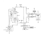
図1は、本実施例における電池システムの構成を示す。本実施例の電池システムは、車両(いわゆるハイブリッド自動車)に搭載されている。この車両は、後述するように、組電池およびエンジンを併用しながら走行することができる。 FIG. 1 shows the configuration of the battery system in this example. The battery system of this embodiment is mounted on a vehicle (a so-called hybrid vehicle). As will be described later, this vehicle can travel while using the assembled battery and the engine together.
組電池10は、直列に接続された複数の単電池11を有する。単電池(本発明のアルカリ二次電池に相当する)11としては、ニッケル水素電池やニッケルカドミウム電池といったアルカリ二次電池が用いられる。単電池11は、公知のように、充放電を行う発電要素と、発電要素を収容する電池ケースとを有する。発電要素は、正極板と、負極板と、正極板および負極板の間に配置されたセパレータとを有する。セパレータには、電解液が染み込んでいる。また、電池ケースの内部において、発電要素の周囲には、余剰液として電解液が存在している。
The assembled
なお、単電池11の代わりに、電池モジュール(本発明のアルカリ二次電池に相当する)を用いることもできる。電池モジュールは、電池モジュールの外装を構成するモジュールケースと、モジュールケースに収容された複数の発電要素とを有する。複数の発電要素は、モジュールケースの内部において、直列に接続されている。複数の電池モジュールを直列に接続することにより、組電池10を構成することができる。
Note that a battery module (corresponding to the alkaline secondary battery of the present invention) may be used instead of the unit cell 11. The battery module includes a module case that forms an exterior of the battery module, and a plurality of power generation elements housed in the module case. The plurality of power generation elements are connected in series inside the module case. The assembled
電池ケースには、公知のように、弁が設けられている。弁は、電池ケースの内部で発生したガスを電池ケースの外部に排出する。単電池11の過充電又は過放電に伴って、電池ケースの内部ではガスが発生する。このガスは、電解液の化学反応などによって発生する。電池ケースの内部は、密閉状態となっているため、ガスの発生に伴って、電池ケースの内部における圧力(内圧)が上昇する。電池ケースの内圧が弁の作動圧に到達すると、弁が閉じ状態から開き状態に変化し、電池ケースの外部にガスが排出される。 As is well known, the battery case is provided with a valve. The valve discharges gas generated inside the battery case to the outside of the battery case. As the unit cell 11 is overcharged or overdischarged, gas is generated inside the battery case. This gas is generated by a chemical reaction of the electrolytic solution. Since the inside of the battery case is in a sealed state, the pressure (internal pressure) inside the battery case increases with the generation of gas. When the internal pressure of the battery case reaches the operating pressure of the valve, the valve changes from the closed state to the open state, and gas is discharged to the outside of the battery case.
監視ユニット(本発明の電圧センサに相当する)20は、各単電池11の電圧値Vbを検出し、検出結果をコントローラ30に出力する。上述したように、複数の電池モジュールによって組電池10を構成したとき、監視ユニット20は、各電池モジュールの電圧値Vbを検出し、検出結果をコントローラ30に出力する。
The monitoring unit (corresponding to the voltage sensor of the present invention) 20 detects the voltage value Vb of each cell 11 and outputs the detection result to the
温度センサ21は、組電池10(単電池11)の温度Tbを検出し、検出結果をコントローラ30に出力する。電流センサ22は、組電池10の電流値Ibを検出し、検出結果をコントローラ30に出力する。本実施例において、組電池10を放電しているときの電流値Ibを正の値とし、組電池10を充電しているときの電流値Ibを負の値とする。
The
コントローラ30は、メモリ31を有する。メモリ31は、コントローラ30が所定処理(特に、本実施例で説明する処理)を行うための各種の情報を記憶する。本実施例では、メモリ31がコントローラ30に内蔵されているが、メモリ31を、コントローラ30の外部に設けることもできる。
The
組電池10の正極端子には、正極ラインPLが接続され、組電池10の負極端子には、負極ラインNLが接続されている。正極ラインPLには、システムメインリレーSMR−Bが設けられている。負極ラインNLには、システムメインリレーSMR−Gが設けられている。システムメインリレーSMR−B,SMR−Gは、コントローラ30からの駆動信号を受けることにより、オンおよびオフの間で切り替わる。
A positive electrode line PL is connected to the positive electrode terminal of the assembled
組電池10は、正極ラインPLおよび負極ラインNLを介して、インバータ23と接続されている。コントローラ30がシステムメインリレーSMR−B,SMR−Gをオンにすることにより、組電池10およびインバータ23が接続される。これにより、図1に示す電池システムが起動状態(Ready-On)になる。
The assembled
コントローラ30は、イグニッションスイッチがオフからオンに切り替わったときに、システムメインリレーSMR−B,SMR−Gをオンにする。イグニッションスイッチがオンからオフに切り替わると、コントローラ30は、システムメインリレーSMR−B,SMR−Gをオフにする。これにより、組電池10およびインバータ23の接続が遮断され、図1に示す電池システムが停止状態(Ready-Off)になる。
The
インバータ23は、組電池10から出力された直流電力を交流電力に変換し、交流電力をモータ・ジェネレータMG2に出力する。モータ・ジェネレータ(本発明のモータに相当する)MG2は、インバータ23から出力された交流電力を受けて、車両を走行させるための運動エネルギ(動力)を生成する。モータ・ジェネレータMG2が生成した運動エネルギを駆動輪24に伝達することにより、車両を走行させることができる。
The
動力分割機構25は、エンジン26の動力を、駆動輪24に伝達したり、モータ・ジェネレータMG1に伝達したりする。モータ・ジェネレータMG1は、エンジン26の動力を受けて発電する。モータ・ジェネレータMG1が生成した電力(交流電力)は、インバータ23を介して、モータ・ジェネレータMG2に供給されたり、組電池10に供給されたりする。モータ・ジェネレータMG1が生成した電力を、モータ・ジェネレータMG2に供給すれば、モータ・ジェネレータMG2が生成した運動エネルギによって、駆動輪24を駆動することができる。モータ・ジェネレータMG1が生成した電力を組電池10に供給すれば、組電池10を充電することができる。
The
車両を減速させたり、停止させたりするとき、モータ・ジェネレータMG2は、車両の制動時に発生する運動エネルギを電気エネルギ(交流電力)に変換する。インバータ23は、モータ・ジェネレータMG2が生成した交流電力を直流電力に変換し、直流電力を組電池10に出力する。これにより、組電池10は、回生電力を蓄えることができる。
When the vehicle is decelerated or stopped, the motor / generator MG2 converts kinetic energy generated during braking of the vehicle into electric energy (AC power). The
システムメインリレーSMR−Bおよびインバータ23の間の正極ラインPLと、システムメインリレーSMR−Gおよびインバータ23の間の負極ラインNLとには、DC/DCコンバータ27が接続されている。電池システムが起動状態にあるとき、DC/DCコンバータ27は、組電池10の出力電圧を降圧し、降圧後の電力を補機28や補機電池29に出力する。組電池10から補機28に電力を供給することにより、例えば、エンジン26を始動させることができる。
A DC / DC converter 27 is connected to the positive line PL between the system main relay SMR-B and the
図1に示す電池システムにおいて、組電池10およびインバータ23の間の電流経路に、昇圧回路を設けることができる。昇圧回路は、組電池10の出力電圧を昇圧し、昇圧後の電力をインバータ23に出力することができる。また、昇圧回路は、インバータ23の出力電圧を降圧し、降圧後の電力を組電池10に出力することができる。
In the battery system shown in FIG. 1, a booster circuit can be provided in the current path between the assembled
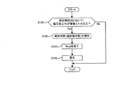
単電池11(発電要素)では、微小な短絡が発生するおそれがある。微小な短絡が発生すると、単電池11が放電し続けてしまい、単電池11が異常状態(過放電状態)となってしまう。ここで、単電池11の異常状態(過放電状態)を確定する処理について、図2に示すフローチャートを用いて説明する。図2に示す処理は、電池システムが起動状態であるときに、コントローラ30によって実行される。
In the unit cell 11 (power generation element), there is a possibility that a minute short circuit may occur. When a minute short circuit occurs, the unit cell 11 continues to be discharged, and the unit cell 11 enters an abnormal state (overdischarge state). Here, the process for determining the abnormal state (overdischarge state) of the unit cell 11 will be described with reference to the flowchart shown in FIG. The process shown in FIG. 2 is executed by the
ステップS101において、コントローラ30は、所定時間内において、単電池11の電圧値Vbが閾値V_th以下であるか否かを判別する。電圧値Vbは、監視ユニット20によって検出される。このため、コントローラ30は、電圧値Vbを監視することにより、所定時間内において、電圧値Vbが閾値V_th以下であるか否かを判別することができる。ここで、組電池10を構成する複数の単電池11において、電圧値Vbのバラツキが発生しているとき、ステップS101の処理では、最も低い電圧値Vbを閾値V_thと比較することができる。
In step S101, the
閾値V_thは、単電池11の過放電状態を判別するための電圧値Vbであり、適宜設定することができる。組電池10(単電池11)の充放電を行うときには、電圧値Vbが上限値および下限値の範囲内で変化するように、組電池10の充放電が制御される。ここで、閾値V_thは、下限値よりも低い電圧値である。閾値V_thを特定する情報は、メモリ31に記憶されている。
The threshold value V_th is a voltage value Vb for determining the overdischarge state of the unit cell 11, and can be set as appropriate. When charging / discharging the assembled battery 10 (unit cell 11), charging / discharging of the assembled
所定時間内において、電圧値Vbが閾値V_th以下となることには、所定時間の間、電圧値Vbが閾値V_th以下となる状態が継続されることと、所定時間の間、電圧値Vbが閾値V_th以下となる状態が繰り返されることとが含まれる。後者の場合には、電圧値Vbが閾値V_th以上となったり、電圧値Vbが閾値V_thよりも低下したりする。 For the voltage value Vb to be equal to or less than the threshold value V_th within the predetermined time, the state in which the voltage value Vb is equal to or less than the threshold value V_th is continued for a predetermined time, and the voltage value Vb is set to the threshold value for the predetermined time. It includes that the state of V_th or less is repeated. In the latter case, the voltage value Vb becomes greater than or equal to the threshold value V_th, or the voltage value Vb falls below the threshold value V_th.
電圧値Vbが低下したときには、モータ・ジェネレータMG1の発電などによって、組電池10が充電される。これにより、上述したように、上限値および下限値の範囲内において、電圧値Vbを変化させることができる。しかし、単電池11に微小な短絡が発生しているときには、電圧値Vbが低下しやすくなっており、電圧値Vbが閾値V_th以下となることがある。
When the voltage value Vb decreases, the assembled
所定時間内において、電圧値Vbが閾値V_th以下ではないとき、コントローラ30は、図2に示す処理を終了する。すなわち、すべての単電池11に関して、電圧値Vbが閾値V_th以下ではないとき、図2に示す処理が終了する。
When the voltage value Vb is not less than or equal to the threshold value V_th within the predetermined time, the
一方、所定時間内において、電圧値Vbが閾値V_th以下であるとき、コントローラ30は、ステップS102において、異常状態(過放電状態)の確定を行う。コントローラ30は、閾値V_th以下の電圧値Vbを示す単電池11が異常状態(過放電状態)であることを確定する。ここでは、少なくとも1つの単電池11の電圧値Vbが閾値V_th以下であるとき、異常状態の確定が行われる。
On the other hand, when the voltage value Vb is equal to or less than the threshold value V_th within the predetermined time, the
異常状態の確定を行うとき、例えば、コントローラ30は、異常状態(過放電状態)を示すフラグを設定することができる。このフラグの設定内容は、メモリ31に記憶される。コントローラ30は、メモリ31に記憶されたフラグの設定内容を確認することにより、単電池11が異常状態(過放電状態)であるか否かを確認することができる。
When determining the abnormal state, for example, the
本実施例において、電圧値Vbが一時的に閾値V_th以下となっただけでは、異常状態を確定しない。上述したように、電圧値Vbが閾値V_th以下となる状態が継続されたり、繰り返されたりしたときに、異常状態を確定している。これにより、異常状態の確定に対する信頼性を確保するようにしている。なお、電圧値Vbが一時的に閾値V_th以下となったときに、異常状態(過放電状態)の確定を行うこともできる。 In the present embodiment, the abnormal state is not determined only when the voltage value Vb temporarily falls below the threshold value V_th. As described above, when the state in which the voltage value Vb is equal to or less than the threshold value V_th is continued or repeated, the abnormal state is determined. Thereby, the reliability with respect to the determination of the abnormal state is ensured. It should be noted that when the voltage value Vb temporarily falls below the threshold value V_th, an abnormal state (overdischarge state) can be determined.
異常状態を確定した後、コントローラ30は、ステップS103において、許容出力電力Woutを低下させる。許容出力電力Woutとは、組電池10を放電することができる上限の電力値である。組電池10を放電するときには、許容出力電力Woutが設定され、組電池10の出力電力が許容出力電力Woutを超えないように、組電池10の放電が制御される。
After determining the abnormal state, the
許容出力電力Woutは、組電池10の温度TbやSOC(State of Charge)に基づいて設定される。SOCとは、満充電容量に対する充電容量の割合である。温度Tbおよび許容出力電力Woutの対応関係を予め定めておけば、温度Tbを検出することにより、この温度Tbに対応した許容出力電力Woutを特定することができる。また、SOCおよび許容出力電力Woutの対応関係を予め定めておけば、SOCを算出(推定)することにより、このSOCに対応した許容出力電力Woutを特定することができる。公知のように、組電池10の電流値Ibや電圧値Vbに基づいて、組電池10のSOCを推定することができる。
The allowable output power Wout is set based on the temperature Tb and SOC (State of Charge) of the assembled
なお、組電池10の充放電を制御するときには、許容出力電力Woutだけでなく、許容入力電力Winも設定される。許容入力電力Winは、組電池10を充電することができる上限の電力値である、許容入力電力Winは、許容出力電力Woutと同様に、組電池10の温度TbやSOCに基づいて設定される。本実施例では、単電池11の過放電を抑制するために、許容出力電力Woutを低下させればよい。
When charging / discharging of the assembled
ステップS103の処理では、温度TbやSOCから特定された許容出力電力Woutを低下させる。すなわち、ステップS103の処理で設定される許容出力電力Woutは、温度TbやSOCから特定される許容出力電力Woutよりも低くなる。許容出力電力Woutを低下させる量は、適宜設定することができる。例えば、電圧値Vbが閾値V_th以下であるときにおいて、電圧値Vbおよび閾値V_thの差が広がるほど、許容出力電力Woutを低下させる量を増加させることができる。許容出力電力Woutを低下させるとき、低下後の許容出力電力Woutは、エンジン26を始動させるために必要な電力以上であることが好ましい。これにより、許容出力電力Woutを低下させても、組電池10の出力電力を用いて、エンジン26を始動させることができる。
In the process of step S103, the allowable output power Wout specified from the temperature Tb and the SOC is reduced. That is, the allowable output power Wout set in the process of step S103 is lower than the allowable output power Wout specified from the temperature Tb and the SOC. The amount by which the allowable output power Wout is reduced can be set as appropriate. For example, when the voltage value Vb is equal to or less than the threshold value V_th, the amount by which the allowable output power Wout is decreased can be increased as the difference between the voltage value Vb and the threshold value V_th increases. When the allowable output power Wout is decreased, the decreased allowable output power Wout is preferably equal to or higher than the power necessary for starting the
ステップS104において、コントローラ30は、ユーザなどに警告を行う。警告を行う手段としては、公知の手段を適宜採用することができる。例えば、ディスプレイへの表示を行ったり、音を出力させたりすることにより、ユーザなどに警告することができる。警告の内容は、組電池10が異常状態であることをユーザなどに認識させる内容であればよい。警告を受けたユーザなどは、安全な場所まで車両を走行(退避走行)させることができる。
In step S104, the
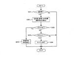
単電池11の異常状態(過放電状態)を確定する処理は、図2に示す処理に限るものではない。例えば、図2に示す処理の代わりに、図3に示す処理を行うことができる。図3において、図2で説明した処理と同じ処理については、同一の符号を用い、詳細な説明は省略する。図3に示す処理では、図2に示すステップS101の処理の代わりに、ステップS105の処理が行われる。 The process for determining the abnormal state (overdischarge state) of the unit cell 11 is not limited to the process shown in FIG. For example, instead of the process shown in FIG. 2, the process shown in FIG. 3 can be performed. 3, the same processes as those described in FIG. 2 are denoted by the same reference numerals, and detailed description thereof is omitted. In the process shown in FIG. 3, the process of step S105 is performed instead of the process of step S101 shown in FIG.
ステップS105において、コントローラ30は、所定時間内において、電圧差ΔVbが閾値ΔV_th以上であるか否かを判別する。電圧差ΔVbとは、各単電池11の電圧値Vbと、基準電圧値Vrefとの差である。電圧値Vbは、監視ユニット20によって検出される。基準電圧値Vrefとしては、例えば、すべての単電池11の電圧値Vbを平均化した値を用いたり、最も高い電圧値Vbを用いたりすることができる。
In step S105, the
各単電池11において、電圧差ΔVbを算出することもできるが、最も低い電圧値Vbを特定し、この電圧値Vbおよび基準電圧値Vrefの差を、電圧差ΔVbとすることもできる。閾値ΔV_thは、単電池11の過放電状態を判別するための電圧差ΔVbであり、適宜設定することができる。電圧差ΔVbが広がるほど、単電池11が放電されやすくなっている。この点に基づいて、閾値ΔV_thを設定すれば、単電池11が過放電状態であるか否かを判別することができる。閾値ΔV_thを特定する情報は、メモリ31に記憶されている。
Although the voltage difference ΔVb can be calculated for each unit cell 11, the lowest voltage value Vb can be specified, and the difference between the voltage value Vb and the reference voltage value Vref can be set as the voltage difference ΔVb. The threshold value ΔV_th is a voltage difference ΔVb for determining the overdischarge state of the cell 11 and can be set as appropriate. The larger the voltage difference ΔVb, the easier the cell 11 is discharged. Based on this point, if the threshold value ΔV_th is set, it can be determined whether or not the cell 11 is in an overdischarged state. Information for specifying the threshold value ΔV_th is stored in the
所定時間内において、電圧差ΔVbが閾値ΔV_th以上となることには、所定時間の間、電圧差ΔVbが閾値ΔV_th以上となる状態が継続されることと、所定時間の間、電圧差ΔVbが閾値ΔV_th以上となる状態が繰り返されることが含まれる。後者の場合には、電圧差ΔVbが閾値ΔV_th以上となったり、電圧差ΔVbが閾値ΔV_thよりも小さくなったりする。 In order for the voltage difference ΔVb to be equal to or greater than the threshold value ΔV_th within the predetermined time, the state where the voltage difference ΔVb is equal to or greater than the threshold value ΔV_th is continued for a predetermined time, and the voltage difference ΔVb is equal to the threshold value for the predetermined time. It includes that the state of ΔV_th or more is repeated. In the latter case, the voltage difference ΔVb becomes greater than or equal to the threshold value ΔV_th, or the voltage difference ΔVb becomes smaller than the threshold value ΔV_th.
所定時間内において、電圧差ΔVbが閾値ΔV_th以上ではないとき、図3に示す処理が終了する。一方、所定時間内において、電圧差ΔVbが閾値ΔV_th以上であるとき、ステップS102〜S104の処理が行われる。 When the voltage difference ΔVb is not greater than or equal to the threshold value ΔV_th within the predetermined time, the process illustrated in FIG. 3 ends. On the other hand, when the voltage difference ΔVb is equal to or greater than the threshold value ΔV_th within the predetermined time, the processes of steps S102 to S104 are performed.
図3に示す処理では、図2に示す処理と同様に、電圧差ΔVbが一時的に閾値ΔV_th以上となっただけでは、異常状態を確定しない。すなわち、電圧差ΔVbが閾値ΔV_th以上となる状態が継続されたり、繰り返されたりしたときに、異常状態を確定している。これにより、異常状態の確定に対する信頼性を確保するようにしている。なお、電圧差ΔVbが一時的に閾値ΔV_th以上となったときに、異常状態を確定することもできる。 In the process shown in FIG. 3, as in the process shown in FIG. 2, the abnormal state is not determined only when the voltage difference ΔVb temporarily exceeds the threshold value ΔV_th. That is, the abnormal state is determined when the state where the voltage difference ΔVb is equal to or greater than the threshold value ΔV_th is continued or repeated. Thereby, the reliability with respect to the determination of the abnormal state is ensured. Note that the abnormal state can also be determined when the voltage difference ΔVb temporarily exceeds the threshold value ΔV_th.
なお、図2に示すステップS101の処理と、図3に示すステップS105の処理とを組み合わせて、異常状態(過放電状態)を確定することもできる。すなわち、所定時間内において、電圧値Vbが閾値V_th以下であるとともに、電圧差ΔVbが閾値ΔV_th以上であるときに、異常状態(過放電状態)を確定することができる。 It should be noted that the abnormal state (overdischarge state) can be determined by combining the process of step S101 shown in FIG. 2 and the process of step S105 shown in FIG. That is, an abnormal state (overdischarge state) can be determined when the voltage value Vb is equal to or less than the threshold value V_th and the voltage difference ΔVb is equal to or greater than the threshold value ΔV_th within a predetermined time.
図2又は図3に示す処理によって、異常状態が確定した後では、図4に示す処理が行われる。図4に示す処理は、コントローラ30によって実行される。コントローラ30は、異常状態を示すフラグが設定されていることを確認した上で、図4に示す処理を開始することができる。図4に示す処理は、所定の周期で繰り返される。
After the abnormal state is determined by the process shown in FIG. 2 or FIG. 3, the process shown in FIG. 4 is performed. The process shown in FIG. 4 is executed by the
ステップS201において、コントローラ30は、組電池10に含まれる少なくとも1つの単電池11が過放電されているか否かを判別する。すなわち、ステップS201の処理では、単電池11が過放電状態であるか否かを判別するようにしている。
In step S <b> 201, the
例えば、単電池11の電圧値Vbが閾値V_th以下であるときに、単電池11が過放電されていることを判別できる。この閾値V_thは、図2に示すステップS101の処理で説明した閾値V_thと同じである。一方、電圧差ΔVbが閾値ΔV_th以上であるときに、単電池11が過放電されていることを判別できる。ここで、電圧差ΔVbおよび閾値ΔV_thは、図3に示すステップS105の処理で説明した電圧差ΔVbおよび閾値ΔV_thと同じである。 For example, when the voltage value Vb of the cell 11 is equal to or less than the threshold value V_th, it can be determined that the cell 11 is overdischarged. This threshold value V_th is the same as the threshold value V_th described in step S101 shown in FIG. On the other hand, when the voltage difference ΔVb is equal to or greater than the threshold value ΔV_th, it can be determined that the unit cell 11 is overdischarged. Here, the voltage difference ΔVb and the threshold value ΔV_th are the same as the voltage difference ΔVb and the threshold value ΔV_th described in step S105 shown in FIG.
単電池11が過放電されていなければ、コントローラ30は、図4に示す処理を終了する。単電池11が過放電されていると、コントローラ30は、ステップS202において、組電池10を放電しているときの電流値Ibを積算し、積算値Sを算出する。単電池11が過放電されるたびに、電流値(放電電流)Ibの積算が行われ、積算値Sは増加し続ける。なお、単電池11が過放電されていなければ、単電池11が放電されても、電流値(放電電流)Ibの積算は行われない。
If the unit cell 11 is not overdischarged, the
ステップS203において、コントローラ30は、ステップS202の処理で算出した積算値Sが第2閾値S_th2以上であるか否かを判別する。第2閾値S_th2は、車両を停止させる必要があるか否かを判別するための値(積算値S)である。後述するように、第2閾値S_th2は、単電池11に含まれる電解液の残量を考慮して設定される。第2閾値S_th2を特定する情報は、メモリ31に記憶されている。
In step S203, the
積算値Sが第2閾値S_th2以上であるとき、コントローラ30は、ステップS204において、電池システムの起動を停止させる。具体的には、コントローラ30は、システムメインリレーSMR−B,SMR−Gをオンからオフに切り替える。ここで、エンジン26が始動しているときには、エンジン26が停止する。これにより、車両が停止する。
When the integrated value S is equal to or greater than the second threshold value S_th2, the
積算値Sが第2閾値S_th2よりも小さいとき、コントローラ30は、ステップS205において、ステップS202の処理で算出された積算値Sが第1閾値S_th1以上であるか否かを判別する。第1閾値S_th1は、第2閾値S_th2よりも小さい値である。第1閾値S_th1は、エンジン26の動力だけを用いて車両を走行させるか否かを判別するための値(積算値S)である。後述するように、第1閾値S_th1は、単電池11に含まれる電解液の残量を考慮して設定される。第1閾値S_th1を特定する情報は、メモリ31に記憶されている。
When the integrated value S is smaller than the second threshold value S_th2, the
積算値Sが第1閾値S_th1以上であるとき、コントローラ30は、ステップS206において、エンジン26の動力だけを用いて車両を走行させる。ステップS206の処理では、電池システムが起動状態となっているが、モータ・ジェネレータMG2の動力を用いた走行は行われない。積算値Sが第1閾値S_th1よりも小さいとき、コントローラ30は、図4に示す処理を終了する。ここで、積算値Sが第1閾値S_th1よりも小さい間は、図2又は図3に示すステップS103の処理によって、許容出力電力Woutが低下したままとなる。
When the integrated value S is equal to or greater than the first threshold value S_th1, the
異常状態(過放電状態)の確定を行ったとき、過放電状態の単電池11(電池ケース)の内部には、電解液が残ったままである。具体的には、発電要素のセパレータに電解液が残っていたり、発電要素の周囲に電解液(余剰液)が残っていたりする。異常状態の確定を行った後において、過放電状態の単電池11を放電すると、電解液が分解される。具体的には、単電池11を放電させるために、電解液に含まれる水分が分解され、電解液の量が減少する。ここで、電解液の分解に伴ってガスが発生する。 When the abnormal state (overdischarge state) is determined, the electrolyte remains in the overdischarged unit cell 11 (battery case). Specifically, the electrolytic solution remains in the separator of the power generation element, or the electrolytic solution (surplus liquid) remains around the power generation element. After the abnormal state is determined, when the overdischarged unit cell 11 is discharged, the electrolytic solution is decomposed. Specifically, in order to discharge the unit cell 11, the moisture contained in the electrolytic solution is decomposed, and the amount of the electrolytic solution is reduced. Here, gas is generated with the decomposition of the electrolytic solution.
電解液の減少量は、過放電状態の単電池11を放電したときの電流値Ibに依存する。すなわち、電流値(放電電流)Ibが大きくなるほど、また、電流値(放電電流)Ibの積算値Sが増加するほど、電解液の減少量が増加する。このため、図5に示すように、積算値Sが増加するほど、電解液の量が減少する。そして、電解液が無くなれば、単電池11を放電させることができない。言い換えれば、電解液が無くなるまでは、単電池11を放電させることができる。 The amount of decrease in the electrolytic solution depends on the current value Ib when the overdischarged unit cell 11 is discharged. That is, as the current value (discharge current) Ib increases and the integrated value S of the current value (discharge current) Ib increases, the amount of decrease in the electrolyte increases. For this reason, as shown in FIG. 5, the amount of the electrolytic solution decreases as the integrated value S increases. And if there is no electrolyte solution, the unit cell 11 cannot be discharged. In other words, the unit cell 11 can be discharged until the electrolyte is exhausted.
本実施例では、積算値Sを算出することにより、電解液の残量(言い換えれば、電解液の減少量)を把握するようにしている。そして、積算値Sを監視して、電解液の残量を把握しながら、過放電状態の単電池11を放電させている。これにより、異常状態(過放電状態)の確定を行った後でも、組電池10(過放電状態の単電池11を含む)を放電させることができる。 In the present embodiment, the remaining amount of the electrolytic solution (in other words, the amount of decrease in the electrolytic solution) is grasped by calculating the integrated value S. The overcharged unit cell 11 is discharged while monitoring the integrated value S and grasping the remaining amount of the electrolytic solution. Thereby, the assembled battery 10 (including the unit cell 11 in the overdischarge state) can be discharged even after the abnormal state (overdischarge state) is determined.
ここで、組電池10の放電電力をモータ・ジェネレータMG2に供給すれば、モータ・ジェネレータMG2の動力を用いて車両を走行させることができる。また、組電池10を放電させることにより、エンジン26を駆動することができ、エンジン26の動力を用いて車両を走行させることができる。異常状態を確定した後も、車両を走行させ続けることにより、異常状態を確定したときに車両を停止させる場合に比べて、車両の退避走行を行うときの走行距離を延ばすことができる。
Here, if the discharge power of the assembled
異常状態の確定が行われたときであれば、通常、単電池11の電解液の量は、ほとんど減少していない。ここで、電解液の蒸発によって発生したガスが、単電池11の電池ケースを透過して、単電池11の外部に移動することがある。これにより、電解液の量が減少することもあるが、このときの電解液の減少量は僅かである。したがって、異常状態が確定したときの電解液の量は、単電池11を製造するときに電池ケースに注入された電解液の量とほぼ等しくなる。 When the abnormal state is confirmed, the amount of the electrolyte solution of the unit cell 11 is usually hardly decreased. Here, gas generated by evaporation of the electrolytic solution may pass through the battery case of the unit cell 11 and move to the outside of the unit cell 11. As a result, the amount of the electrolytic solution may decrease, but the amount of decrease in the electrolytic solution at this time is slight. Therefore, the amount of the electrolytic solution when the abnormal state is determined is substantially equal to the amount of the electrolytic solution injected into the battery case when the unit cell 11 is manufactured.
異常状態が確定したときの電解液の量を把握できれば、電解液が無くなるまでの積算値Sを把握することができる。実験などによって、過放電状態の単電池11を放電したときの電流値Ibと、電解液の減少量との関係を予め求めておけば、電解液が無くなるまでの積算値Sを算出することができる。第2閾値S_th2は、電解液が無くなるときの積算値Sよりも小さい値にすることができる。また、第1閾値S_th1は、第2閾値S_th2よりも小さい値にすることができる。 If the amount of the electrolytic solution when the abnormal state is determined can be grasped, the integrated value S until the electrolytic solution runs out can be grasped. If the relationship between the current value Ib when the over-discharged unit cell 11 is discharged and the amount of decrease in the electrolytic solution is obtained in advance by experiments or the like, the integrated value S until the electrolytic solution runs out can be calculated. it can. The second threshold value S_th2 can be set to a value smaller than the integrated value S when there is no electrolyte solution. Further, the first threshold value S_th1 can be set to a value smaller than the second threshold value S_th2.
図6は、図4に示す処理を行ったときにおいて、電圧値Vb、電流値Ibおよび積算値Sの変化を示す図(一例)である。図6において、縦軸は、電圧値Vb、電流値Ibおよび積算値Sをそれぞれ示す。図6の横軸は時間である。図6に示す例では、電圧値Vbが閾値V_th以下であるか否かを判別することにより、単電池11が過放電されているか否かを判別している。 FIG. 6 is a diagram (an example) showing changes in the voltage value Vb, the current value Ib, and the integrated value S when the process shown in FIG. 4 is performed. In FIG. 6, the vertical axis indicates the voltage value Vb, the current value Ib, and the integrated value S, respectively. The horizontal axis in FIG. 6 is time. In the example shown in FIG. 6, it is determined whether or not the unit cell 11 is overdischarged by determining whether or not the voltage value Vb is equal to or less than the threshold value V_th.
図6に示す例では、時間t1において、異常状態(過放電状態)の確定が行われている。このため、時間t1以降では、許容出力電力Woutを低下させている。許容出力電力Woutを低下させることにより、組電池10を放電するときの電流値Ibを低下させることができる。電流値(放電電流)Ibを低下させれば、過放電状態の単電池11において、電解液の減少量を抑制することができる。すなわち、単位時間あたりの電解液の減少量を低下させることができ、過放電状態の単電池11を放電させることができる時間を延ばすことができる。なお、異常状態を確定した後において、許容出力電力Woutを低下させなくてもよい。すなわち、図2又は図3において、ステップS103の処理を省略することもできる。
In the example shown in FIG. 6, the abnormal state (overdischarge state) is determined at time t1. For this reason, after the time t1, the allowable output power Wout is decreased. By reducing the allowable output power Wout, the current value Ib when discharging the assembled
また、時間t1以降では、図4に示す処理が行われ、電解液を分解させながら、過放電状態の単電池11が放電される。これにより、単電池11が過放電されるたびに、電流値(放電電流)Ibが積算され、積算値Sが増加する。時間t1から時間t2の間では、電圧値Vbが閾値V_th以下となるため、積算値Sが増加する。 Further, after time t1, the process shown in FIG. 4 is performed, and the overdischarged unit cell 11 is discharged while decomposing the electrolytic solution. Thereby, whenever the cell 11 is overdischarged, the current value (discharge current) Ib is integrated, and the integrated value S increases. Between time t1 and time t2, voltage value Vb is equal to or lower than threshold value V_th, and thus integrated value S increases.
なお、図6では、積算値Sが直線的に増加しているが、実際には、単電池11が過放電されているときの電流値(放電電流)Ibの分だけ増加する。また、電解液の分解に伴ってガスが発生するため、単電池11(電池ケース)に設けられた弁が閉じ状態から開き状態に変化することがある。 In FIG. 6, the integrated value S increases linearly, but actually increases by the amount of the current value (discharge current) Ib when the unit cell 11 is overdischarged. Further, since gas is generated with the decomposition of the electrolytic solution, a valve provided in the unit cell 11 (battery case) may change from a closed state to an open state.
時間t2以降では、電流値Ibが充電側にシフトしており、電圧値Vbは閾値V_thよりも高くなっている。このときには、単電池11が過放電されていなく、単電池11を放電したとしても、電解液の量は減少しない。したがって、時間t2以降では、電流値(放電電流)Ibの積算が行われず、積算値Sも増加しない。 After time t2, the current value Ib is shifted to the charging side, and the voltage value Vb is higher than the threshold value V_th. At this time, the unit cell 11 is not overdischarged, and even if the unit cell 11 is discharged, the amount of the electrolyte does not decrease. Therefore, after time t2, the current value (discharge current) Ib is not integrated, and the integrated value S does not increase.
時間t3では、電流値Ibが放電側にシフトし、電圧値Vbが閾値V_th以下になる。このときには、単電池11が過放電されており、単電池11の放電に伴って、電解液の量が減少する。そこで、電流値(放電電流)Ibの積算が再開され、積算値Sが増加する。時間t4では、積算値Sが第1閾値S_th1に到達している。これにより、エンジン26の動力だけを用いた走行に切り替わる。すなわち、時間t4までは、エンジン26の動力だけでなく、モータ・ジェネレータMG2の動力を用いて、車両を走行させることができる。
At time t3, the current value Ib shifts to the discharge side, and the voltage value Vb becomes equal to or less than the threshold value V_th. At this time, the unit cell 11 is overdischarged, and the amount of the electrolytic solution decreases as the unit cell 11 is discharged. Therefore, the integration of the current value (discharge current) Ib is restarted, and the integrated value S increases. At time t4, the integrated value S reaches the first threshold value S_th1. Thereby, it switches to driving | running | working using only the motive power of the
時間t4以降では、モータ・ジェネレータMG2の動力を用いた走行が行われなくなるが、補機28の動作(エンジン26の駆動)などによって、組電池10が放電される。このため、時間t4以降でも、電圧値Vbが閾値V_th以下となることがある。時間t4以降では、電圧値Vbが閾値V_th以下となっているため、電流値(放電電流)Ibの積算が行われ、積算値Sが増加する。積算値Sが増加し続け、時間t5において、積算値Sが第2閾値S_th2に到達すると、電池システムの起動が停止される。これにより、車両が停止する。
After time t4, traveling using the power of the motor / generator MG2 is not performed, but the assembled
本実施例によれば、異常状態(過放電状態)を確定した後であっても、時間t1から時間t5までの間、車両を走行させ続けることができる。これにより、時間t1において、車両を停止させたときに比べて、退避走行を行うときの走行距離を延ばすことができる。 According to the present embodiment, the vehicle can continue to travel from time t1 to time t5 even after the abnormal state (overdischarge state) is determined. Thereby, at the time t1, compared with the time when the vehicle is stopped, the travel distance when the retreat travel is performed can be extended.
本実施例では、ハイブリッド自動車について説明したが、これに限るものではない。すなわち、いわゆる電気自動車についても、本発明を適用することができる。電気自動車とは、車両を走行させる動力源として、組電池10だけを備えた車両である。電気自動車では、組電池10の放電電力を受けたモータ・ジェネレータが、車両を走行させるための動力を生成する。
In this embodiment, a hybrid vehicle has been described, but the present invention is not limited to this. That is, the present invention can also be applied to so-called electric vehicles. An electric vehicle is a vehicle provided with only the assembled
電気自動車では、本実施例と同様に、異常状態(過放電状態)を確定した後であっても、電解液の量を減少させながら、組電池10(過放電状態の単電池11)を放電させることができる。これにより、異常状態(過放電状態)を確定した後も、モータ・ジェネレータの動力を用いて、電気自動車を走行させ続けることができる。したがって、本実施例と同様に、退避走行を行うときの走行距離を延ばすことができる。 In the electric vehicle, as in the present embodiment, even after an abnormal state (overdischarge state) is determined, the battery pack 10 (overdischarged unit cell 11) is discharged while reducing the amount of the electrolyte. Can be made. As a result, the electric vehicle can continue to run using the power of the motor / generator even after the abnormal state (overdischarge state) is determined. Therefore, as in this embodiment, it is possible to extend the travel distance when performing retreat travel.
10:組電池、11:単電池、20:監視ユニット、21:温度センサ、
22:電流センサ、23:インバータ、MG1,MG2:モータ・ジェネレータ、
24:駆動輪、25:動力分割機構、26:エンジン、27:DC/DCコンバータ、
28:補機、29:補機電池、30:コントローラ、31:メモリ、PL:正極ライン、NL:負極ライン、SMR−B,SMR−G:システムメインリレー
10: assembled battery, 11: single cell, 20: monitoring unit, 21: temperature sensor,
22: current sensor, 23: inverter, MG1, MG2: motor / generator,
24: Drive wheel, 25: Power split mechanism, 26: Engine, 27: DC / DC converter,
28: Auxiliary machine, 29: Auxiliary battery, 30: Controller, 31: Memory, PL: Positive line, NL: Negative line, SMR-B, SMR-G: System main relay
Claims (4)
前記組電池の放電電力を受けて、車両を走行させる動力を生成するモータと、
前記車両を走行させる動力を生成するエンジンと、
前記組電池の電流値を検出する電流センサと、
前記各アルカリ二次電池の電圧値を検出する電圧センサと、
前記電圧値に基づいて、前記アルカリ二次電池が過放電状態であるか否かを判別するコントローラと、を有し、
前記コントローラは、
前記アルカリ二次電池が過放電状態であることを判別した後、
過放電状態の前記アルカリ二次電池に含まれる電解液を分解させながら前記組電池を放電させて、前記モータの動力を用いた走行を行わせ、
前記電解液を分解させる放電を行っている間の前記電流値を積算した積算値が第1閾値よりも小さい間、前記組電池の放電を許容する上限の電力値を低下させ、
前記積算値が前記第1閾値以上であるとき、前記モータの動力を用いずに、前記エンジンの動力を用いた走行を行わせ、
前記積算値が前記第1閾値よりも大きい第2閾値以上であるとき、前記組電池の充放電を停止させるとともに、前記エンジンを停止させることを特徴とする車両。 An assembled battery in which a plurality of alkaline secondary batteries are connected in series;
A motor that receives the discharge power of the assembled battery and generates power for running the vehicle;
An engine for generating power for running the vehicle;
A current sensor for detecting a current value of the assembled battery;
A voltage sensor for detecting a voltage value of each of the alkaline secondary batteries;
A controller for determining whether or not the alkaline secondary battery is in an overdischarged state based on the voltage value;
The controller is
After determining that the alkaline secondary battery is in an overdischarged state,
Discharging the assembled battery while decomposing the electrolyte contained in the alkaline secondary battery in an overdischarged state, and running using the power of the motor ;
While the integrated value obtained by integrating the current value during the discharge for decomposing the electrolytic solution is smaller than the first threshold, the upper limit power value that allows the discharge of the assembled battery is reduced,
When the integrated value is equal to or greater than the first threshold value, without using the power of the motor, running using the power of the engine is performed.
When the integrated value is not smaller than the second threshold value larger than the first threshold value, it stops the charging and discharging of the battery pack, the vehicle, characterized in Rukoto to stop the engine.
前記組電池の放電電力を受けて、車両を走行させる動力を生成するモータと、
前記組電池の放電電力を受けて始動し、前記車両を走行させる動力を生成するエンジンと、
前記組電池の電流値を検出する電流センサと、
前記各アルカリ二次電池の電圧値を検出する電圧センサと、
前記電圧値に基づいて、前記アルカリ二次電池が過放電状態であるか否かを判別するコントローラと、を有し、
前記コントローラは、
前記アルカリ二次電池が過放電状態であることを判別した後、
過放電状態の前記アルカリ二次電池に含まれる電解液を分解させながら前記組電池を放電させて、前記モータの動力を用いた走行を行わせ、
前記電解液を分解させる放電を行っている間の前記電流値を積算した積算値が第1閾値よりも小さい間、前記組電池の放電を許容する上限の電力値を低下させ、
前記積算値が前記第1閾値よりも小さいとき、前記エンジンを始動させるための電力以上の範囲内において、前記上限の電力値を低下させることを特徴とする車両。 An assembled battery in which a plurality of alkaline secondary batteries are connected in series;
A motor that receives the discharge power of the assembled battery and generates power for running the vehicle;
An engine start receiving discharge power of the battery pack generates the power for running the vehicle,
A current sensor for detecting a current value of the assembled battery;
A voltage sensor for detecting a voltage value of each of the alkaline secondary batteries;
A controller for determining whether or not the alkaline secondary battery is in an overdischarged state based on the voltage value;
The controller is
After determining that the alkaline secondary battery is in an overdischarged state,
Discharging the assembled battery while decomposing the electrolyte contained in the alkaline secondary battery in an overdischarged state, and running using the power of the motor;
While the integrated value obtained by integrating the current value during the discharge for decomposing the electrolytic solution is smaller than the first threshold, the upper limit power value that allows the discharge of the assembled battery is reduced,
When the integrated value is smaller than the first threshold value, in the range of more power for starting the engine, the car you and decreases the power value of the upper limit both.
Priority Applications (5)
| Application Number | Priority Date | Filing Date | Title |
|---|---|---|---|
| JP2014080610A JP6237425B2 (en) | 2014-04-09 | 2014-04-09 | vehicle |
| CN201580030420.7A CN106415980B (en) | 2014-04-09 | 2015-03-10 | The vehicle of travel motor is installed |
| EP15713578.1A EP3129252B1 (en) | 2014-04-09 | 2015-03-10 | Vehicle on which traveling motor is mounted |
| US15/302,685 US10086823B2 (en) | 2014-04-09 | 2015-03-10 | Vehicle on which traveling motor is mounted |
| PCT/IB2015/000303 WO2015155582A1 (en) | 2014-04-09 | 2015-03-10 | Vehicle on which traveling motor is mounted |
Applications Claiming Priority (1)
| Application Number | Priority Date | Filing Date | Title |
|---|---|---|---|
| JP2014080610A JP6237425B2 (en) | 2014-04-09 | 2014-04-09 | vehicle |
Publications (2)
| Publication Number | Publication Date |
|---|---|
| JP2015202005A JP2015202005A (en) | 2015-11-12 |
| JP6237425B2 true JP6237425B2 (en) | 2017-11-29 |
Family
ID=52781134
Family Applications (1)
| Application Number | Title | Priority Date | Filing Date |
|---|---|---|---|
| JP2014080610A Active JP6237425B2 (en) | 2014-04-09 | 2014-04-09 | vehicle |
Country Status (5)
| Country | Link |
|---|---|
| US (1) | US10086823B2 (en) |
| EP (1) | EP3129252B1 (en) |
| JP (1) | JP6237425B2 (en) |
| CN (1) | CN106415980B (en) |
| WO (1) | WO2015155582A1 (en) |
Family Cites Families (16)
| Publication number | Priority date | Publication date | Assignee | Title |
|---|---|---|---|---|
| US5424145A (en) * | 1992-03-18 | 1995-06-13 | Battery Technologies Inc. | High capacity rechargeable cell having manganese dioxide electrode |
| JP3826567B2 (en) * | 1998-05-28 | 2006-09-27 | トヨタ自動車株式会社 | Battery control device |
| JP3360613B2 (en) * | 1998-06-25 | 2002-12-24 | トヨタ自動車株式会社 | Battery control device |
| TW510977B (en) * | 2000-03-13 | 2002-11-21 | Nippon Telegraph & Telephone | Capacity estimation method, degradation estimation method and degradation estimation apparatus for lithium-ion cells, and lithium-ion batteries |
| JP3857146B2 (en) * | 2002-01-16 | 2006-12-13 | 本田技研工業株式会社 | Control device for hybrid vehicle |
| JP4960656B2 (en) * | 2006-06-13 | 2012-06-27 | プライムアースEvエナジー株式会社 | Battery control device and program |
| JP5076378B2 (en) * | 2006-07-03 | 2012-11-21 | マツダ株式会社 | Battery temperature control device |
| JPWO2008149475A1 (en) * | 2007-06-08 | 2010-08-19 | パナソニック株式会社 | Power supply system and battery pack control method |
| JP4794504B2 (en) | 2007-06-12 | 2011-10-19 | 三洋電機株式会社 | Power supply control method |
| JP2009089569A (en) * | 2007-10-03 | 2009-04-23 | Panasonic Corp | Power supply system |
| JP5210591B2 (en) * | 2007-10-15 | 2013-06-12 | トヨタ自動車株式会社 | Secondary battery control system, electric vehicle equipped with the same, and secondary battery control method |
| JP4744622B2 (en) * | 2009-07-01 | 2011-08-10 | トヨタ自動車株式会社 | Vehicle control device |
| JP5305025B2 (en) * | 2009-07-06 | 2013-10-02 | スズキ株式会社 | Hybrid vehicle |
| JP5472609B2 (en) * | 2009-11-12 | 2014-04-16 | ダイムラー・アクチェンゲゼルシャフト | Drive control device for hybrid vehicle |
| KR101905076B1 (en) | 2012-02-02 | 2018-10-08 | 삼성에스디아이 주식회사 | Electric tool with controller of battery pack and the control method thereof |
| US11239671B2 (en) * | 2012-10-10 | 2022-02-01 | Mitsubishi Electric Corporation | In-vehicle power storage device and control method thereof |
-
2014
- 2014-04-09 JP JP2014080610A patent/JP6237425B2/en active Active
-
2015
- 2015-03-10 WO PCT/IB2015/000303 patent/WO2015155582A1/en active Application Filing
- 2015-03-10 CN CN201580030420.7A patent/CN106415980B/en active Active
- 2015-03-10 EP EP15713578.1A patent/EP3129252B1/en active Active
- 2015-03-10 US US15/302,685 patent/US10086823B2/en active Active
Also Published As
| Publication number | Publication date |
|---|---|
| WO2015155582A1 (en) | 2015-10-15 |
| US20170036665A1 (en) | 2017-02-09 |
| JP2015202005A (en) | 2015-11-12 |
| CN106415980A (en) | 2017-02-15 |
| CN106415980B (en) | 2018-12-11 |
| US10086823B2 (en) | 2018-10-02 |
| EP3129252A1 (en) | 2017-02-15 |
| EP3129252B1 (en) | 2020-12-09 |
Similar Documents
| Publication | Publication Date | Title |
|---|---|---|
| JP5818048B2 (en) | Hybrid battery system for electric vehicles | |
| KR102007360B1 (en) | Vehicle driven by motor and control method of charging and discharging of secondary battery provided in vehicle | |
| JP5720538B2 (en) | Storage device control device | |
| JP5796457B2 (en) | Battery system and battery system control method | |
| JP2015048064A (en) | Vehicle | |
| CN107097647B (en) | Method of supplying power to and power supply system | |
| JP2019106333A (en) | Battery system and capacity recovery method for lithium ion secondary battery | |
| JP2013158184A (en) | Vehicle control device | |
| KR101759627B1 (en) | Vehicle | |
| JP2013090474A (en) | Power storage system and method for detecting abnormality in current sensor | |
| JP2010011619A (en) | Charging control method and charge controller of battery | |
| JP2015231763A (en) | Hybrid electric vehicle | |
| CN104067438B (en) | The control device of lithium ion battery and the restored method of lithium ion battery | |
| JP2018077999A (en) | Cell system | |
| JP2012050281A (en) | Battery charging system of electric vehicle | |
| JP2014223003A (en) | Power storage system | |
| JP6237425B2 (en) | vehicle | |
| JP2016067077A (en) | Electric power storage system | |
| JP2016011054A (en) | vehicle | |
| JP6102714B2 (en) | Power storage system | |
| JP6171989B2 (en) | Power storage system | |
| JP2013071602A (en) | Device and method for controlling hybrid vehicle |
Legal Events
| Date | Code | Title | Description |
|---|---|---|---|
| A621 | Written request for application examination |
Free format text: JAPANESE INTERMEDIATE CODE: A621 Effective date: 20161007 |
|
| A977 | Report on retrieval |
Free format text: JAPANESE INTERMEDIATE CODE: A971007 Effective date: 20170719 |
|
| A131 | Notification of reasons for refusal |
Free format text: JAPANESE INTERMEDIATE CODE: A131 Effective date: 20170725 |
|
| A521 | Request for written amendment filed |
Free format text: JAPANESE INTERMEDIATE CODE: A523 Effective date: 20170914 |
|
| TRDD | Decision of grant or rejection written | ||
| A01 | Written decision to grant a patent or to grant a registration (utility model) |
Free format text: JAPANESE INTERMEDIATE CODE: A01 Effective date: 20171003 |
|
| A61 | First payment of annual fees (during grant procedure) |
Free format text: JAPANESE INTERMEDIATE CODE: A61 Effective date: 20171016 |
|
| R151 | Written notification of patent or utility model registration |
Ref document number: 6237425 Country of ref document: JP Free format text: JAPANESE INTERMEDIATE CODE: R151 |