JP6235238B2 - Spinning reel - Google Patents
Spinning reel Download PDFInfo
- Publication number
- JP6235238B2 JP6235238B2 JP2013107172A JP2013107172A JP6235238B2 JP 6235238 B2 JP6235238 B2 JP 6235238B2 JP 2013107172 A JP2013107172 A JP 2013107172A JP 2013107172 A JP2013107172 A JP 2013107172A JP 6235238 B2 JP6235238 B2 JP 6235238B2
- Authority
- JP
- Japan
- Prior art keywords
- cover
- ring
- rotor
- way clutch
- clutch assembly
- Prior art date
- Legal status (The legal status is an assumption and is not a legal conclusion. Google has not performed a legal analysis and makes no representation as to the accuracy of the status listed.)
- Active
Links
Images


Classifications
-
- A—HUMAN NECESSITIES
- A01—AGRICULTURE; FORESTRY; ANIMAL HUSBANDRY; HUNTING; TRAPPING; FISHING
- A01K—ANIMAL HUSBANDRY; CARE OF BIRDS, FISHES, INSECTS; FISHING; REARING OR BREEDING ANIMALS, NOT OTHERWISE PROVIDED FOR; NEW BREEDS OF ANIMALS
- A01K89/00—Reels
- A01K89/01—Reels with pick-up, i.e. with the guiding member rotating and the spool not rotating during normal retrieval of the line
- A01K89/01121—Frame details
- A01K89/011221—Frame details with line or water shields
-
- A—HUMAN NECESSITIES
- A01—AGRICULTURE; FORESTRY; ANIMAL HUSBANDRY; HUNTING; TRAPPING; FISHING
- A01K—ANIMAL HUSBANDRY; CARE OF BIRDS, FISHES, INSECTS; FISHING; REARING OR BREEDING ANIMALS, NOT OTHERWISE PROVIDED FOR; NEW BREEDS OF ANIMALS
- A01K89/00—Reels
- A01K89/01—Reels with pick-up, i.e. with the guiding member rotating and the spool not rotating during normal retrieval of the line
- A01K89/01121—Frame details
- A01K89/01123—Frame disassembly features
Landscapes
- Life Sciences & Earth Sciences (AREA)
- Environmental Sciences (AREA)
- Animal Husbandry (AREA)
- Biodiversity & Conservation Biology (AREA)
Description
本発明は、釣り用リール、特に、釣り糸を前方に繰り出すスピニングリールに関する。 The present invention relates to a fishing reel, and more particularly to a spinning reel that feeds a fishing line forward.
スピニングリールは、ハンドルと、ハンドルを回転自在に支持するリール本体と、ロータと、スプールと、ロータ駆動機構と、逆転防止機構と、を備えている。ロータは、筒状の装着部を有し、リール本体に回転自在に装着される。スプールは、ロータによって釣り糸が巻き付けられる。ロータ駆動機構は、ハンドルの回転によって回転する駆動ギアと、駆動ギアに噛み合いロータを回転させるピニオンギアと、を有している。リール本体の前部には、逆転防止機構を取り付けるための円形の取付部が形成される。逆転防止機構は、ピニオンギアを介してロータの糸繰り出し方向の回転を禁止する。逆転防止機構は、ローラ型のワンウェイクラッチ組立体を有している。ワンウェイクラッチ組立体は、ねじ部材によってリール本体の取付部に固定される。 The spinning reel includes a handle, a reel body that rotatably supports the handle, a rotor, a spool, a rotor drive mechanism, and a reverse rotation prevention mechanism. The rotor has a cylindrical mounting portion and is rotatably mounted on the reel body. The spool is wound with a fishing line by a rotor. The rotor drive mechanism has a drive gear that rotates by rotation of the handle and a pinion gear that meshes with the drive gear and rotates the rotor. A circular attachment portion for attaching the reverse rotation prevention mechanism is formed at the front portion of the reel body. The reverse rotation prevention mechanism prohibits rotation of the rotor in the yarn unwinding direction via the pinion gear. The reverse rotation prevention mechanism has a roller type one-way clutch assembly. The one-way clutch assembly is fixed to the mounting portion of the reel body by a screw member.
このような構成の逆転防止機構を有するスピニングリールにおいて、逆転防止機構と取付部との隙間から液体が浸入するのを防止するために、ワンウェイクラッチ組立体の外周部面及びリール本体の取付部の外周面を覆う合成ゴム製の薄肉筒状のシールリングを有するものが知られている(例えば、特許文献1参照)。これにより、ワンウェイクラッチ組立体の外周面及びワンウェイクラッチ組立体とリール本体の取付部との隙間から液体がワンウェイクラッチ組立体の内部及びリール本体の内部に浸入するのを防止できる。 In the spinning reel having the reverse rotation prevention mechanism having such a configuration, in order to prevent liquid from entering through the gap between the reverse rotation prevention mechanism and the mounting portion, the outer peripheral surface of the one-way clutch assembly and the mounting portion of the reel body are arranged. One having a thin cylindrical seal ring made of synthetic rubber covering the outer peripheral surface is known (see, for example, Patent Document 1). Accordingly, it is possible to prevent liquid from entering the inside of the one-way clutch assembly and the inside of the reel body from the outer peripheral surface of the one-way clutch assembly and the gap between the one-way clutch assembly and the mounting portion of the reel body.
従来のスピニングリールでは、合成樹脂製の薄肉筒状のシールリングによってワンウェイクラッチ組立体及びリール本体の取付部の外周面を覆っている。このため、経年変化によってシールリングが劣化し、防水性能が低下するおそれがある。 In the conventional spinning reel, the outer peripheral surfaces of the attachment portions of the one-way clutch assembly and the reel body are covered with a thin cylindrical seal ring made of synthetic resin. For this reason, there is a possibility that the seal ring is deteriorated due to secular change and the waterproof performance is lowered.
本発明の課題は、逆転防止機構のワンウェイクラッチ組立体をリール本体の前部に固定するスピニングリールにおいて、ワンウェイクラッチ組立体とリール本体とを間からの液体の浸入をさらに確実に防止できるようにすることにある。 An object of the present invention is to provide a spinning reel in which a one-way clutch assembly of a reverse rotation prevention mechanism is fixed to a front portion of a reel body, so that liquid can be more reliably prevented from entering between the one-way clutch assembly and the reel body. There is to do.
本発明に係るスピニングリールは、釣り糸を前方に繰り出すリールである。スピニングリールは、ハンドルと、リール本体と、ロータと、スプールと、ロータ駆動機構と、逆転防止機構と、を備える。リール本体は、釣り竿を装着可能な竿装着部と、前部に設けられる円形の取付部と、を有し、ハンドルを回転自在に支持する。ロータは、筒状の装着部を有し、リール本体に回転自在に装着される。スプールは、リール本体に前後往復移動可能に装着され、ロータによって釣り糸が巻き付けられる。ロータ駆動機構は、フェースギア歯を有し、ハンドルの回転に連動して回転する駆動ギア、及びロータの装着部が前部に一体回転可能に連結され駆動ギアにかみ合う筒状のピニオンギア、を有する。逆転防止機構は、ロータの糸繰り出し方向の回転を禁止する。逆転防止機構は、ワンウェイクラッチ組立体と、カバー部材と、第1シール部材と、第2シール部材と、を備える。ワンウェイクラッチ組立体は、リール本体の取付部に着脱可能に取り付けられる内輪遊転型のものである。カバー部材は、ワンウェイクラッチ組立体の前面を覆いかつピニオンギアが貫通可能なリング状の底部、及び底部の外周部に一体形成され、ワンウェイクラッチ組立体の外周部と取付部の外周部とを覆う筒状部、を有する剛体製である。第1シール部材は、取付部と筒状部との隙間をシールする。第2シール部材は、ロータの装着部とカバー部材の底部との隙間をシールする。 The spinning reel according to the present invention is a reel that feeds a fishing line forward. The spinning reel includes a handle, a reel body, a rotor, a spool, a rotor drive mechanism, and a reverse rotation prevention mechanism. The reel body has a rod mounting portion on which a fishing rod can be mounted and a circular mounting portion provided at the front portion, and rotatably supports the handle. The rotor has a cylindrical mounting portion and is rotatably mounted on the reel body. The spool is attached to the reel body so as to be movable back and forth, and a fishing line is wound around the rotor. The rotor drive mechanism has a face gear tooth, a drive gear that rotates in conjunction with the rotation of the handle, and a cylindrical pinion gear that is coupled to the front portion so that the rotor mounting portion is integrally rotatable and meshes with the drive gear. Have. The reverse rotation prevention mechanism prohibits rotation of the rotor in the yarn unwinding direction. The reverse rotation prevention mechanism includes a one-way clutch assembly, a cover member, a first seal member, and a second seal member. The one-way clutch assembly is an inner ring idle type that is detachably attached to the attachment portion of the reel body. The cover member covers the front surface of the one-way clutch assembly and is integrally formed on the ring-shaped bottom portion through which the pinion gear can pass and the outer peripheral portion of the bottom portion, and covers the outer peripheral portion of the one-way clutch assembly and the outer peripheral portion of the mounting portion. It is made of a rigid body having a cylindrical portion. The first seal member seals the gap between the attachment portion and the cylindrical portion. The second seal member seals a gap between the mounting portion of the rotor and the bottom portion of the cover member.
このスピニングリールでは、ワンウェイクラッチ組立体の外周部と取付部の外周部が剛体製のカバー部材の筒状部によって覆われるとともに、ワンウェイクラッチ組立体の前面がカバー部材の底部によって覆われる。また、筒状部と取付部との間の隙間が第1シール部材によってシールされ、ピニオンギアに装着されるロータの装着部とカバー部材の底部との隙間が第2シール部材によってシールされる。ここでは、剛体製のカバー部材によって取付部及びワンウェイクラッチ組立体の外周部を覆うとともに、ワンウェイクラッチ組立体の前面を覆い、第1シール部材によって取付部とカバー部材の筒状部との隙間をシールする。また、第2シール部材によってカバー部材の底部とロータの装着部との隙間をシールする。このため、カバー部材が経年劣化しにくくなり、ワンウェイクラッチ組立体とリール本体とを間からの液体の浸入をさらに確実に防止できるようにすることになる。 In this spinning reel, the outer peripheral part of the one-way clutch assembly and the outer peripheral part of the mounting part are covered by the cylindrical part of the cover member made of a rigid body, and the front surface of the one-way clutch assembly is covered by the bottom part of the cover member. Further, the gap between the cylindrical portion and the attachment portion is sealed by the first seal member, and the gap between the mounting portion of the rotor attached to the pinion gear and the bottom portion of the cover member is sealed by the second seal member. Here, the mounting portion and the outer periphery of the one-way clutch assembly are covered by a rigid cover member, the front surface of the one-way clutch assembly is covered, and a gap between the mounting portion and the cylindrical portion of the cover member is formed by the first seal member. Seal. Further, the gap between the bottom portion of the cover member and the mounting portion of the rotor is sealed by the second seal member. For this reason, the cover member is unlikely to deteriorate over time, and liquid can be more reliably prevented from entering between the one-way clutch assembly and the reel body.
第1シール部材は、取付部の外周部に形成された環状溝に装着され、筒状部の内周面に接触して配置されてもよい。この場合には、第1シール部材が環状溝に装着されるので、カバー部材を取付部に装着しやすい。 The first seal member may be mounted in an annular groove formed on the outer peripheral portion of the attachment portion, and may be disposed in contact with the inner peripheral surface of the cylindrical portion. In this case, since the first seal member is attached to the annular groove, it is easy to attach the cover member to the attachment portion.
環状溝は、取付部の前面よりも後方に配置されてもよい。第1シール部材は、環状溝に装着されるOリングである。この場合には、汎用のOリングを用いてシールできるので、シールコストを下げることができる。 The annular groove may be arranged behind the front surface of the attachment portion. The first seal member is an O-ring attached to the annular groove. In this case, since a general-purpose O-ring can be used for sealing, the sealing cost can be reduced.
ワンウェイクラッチ組立体は、取付部に取付可能であり外周部を有する円形のケース部材と、ピニオンギアに一体回転可能に連結される内輪と、ケース部材に回転不能に設けられる外輪と、内輪と外輪との間に配置された複数の転動体と、を有してもよい。カバー部材は、外輪の前面に配置され転動体を抜け止めする底部及び筒状部を有する第1カバー部と、第1カバー部の底部の前面に設けられ、内周部において第1カバー部との間で第2シール部材の外周部を挟持するリング状の第2カバー部と、を有する。この場合にはカバー部材が2つの部材に分割されるので、第2シール部材を伸縮させる必要がなくなり、第2シール部材を装着しやすい。 The one-way clutch assembly includes a circular case member that can be attached to the attachment portion and has an outer peripheral portion, an inner ring that is connected to the pinion gear so as to be integrally rotatable, an outer ring that is non-rotatably provided on the case member, and an inner ring and an outer ring And a plurality of rolling elements arranged between the two. The cover member is provided on the front surface of the bottom portion of the first cover portion, the first cover portion having a bottom portion and a cylindrical portion that are disposed on the front surface of the outer ring and prevents the rolling elements from coming off, A ring-shaped second cover portion that sandwiches the outer peripheral portion of the second seal member therebetween. In this case, since the cover member is divided into two members, it is not necessary to expand and contract the second seal member, and the second seal member can be easily attached.
ワンウェイクラッチ組立体は、取付部に取付可能であり外周部を有する円形のケース部材と、ピニオンギアに一体回転可能に連結される内輪と、ケース部材に回転不能に設けられる外輪と、内輪と外輪との間に配置された複数の転動体と、を有してもよい。カバー部材は、外輪の前面に隙間をあけて配置された底部及び筒状部を有する第1カバー部と、底部と外輪との隙間に配置され、転動体を抜け止めし、内周部で第1カバー部との間で第2シール部材の外周部を挟持する第2カバー部と、を有する。この場合にはカバー部材が2つの部材に分割されるので、第2シール部材を伸縮させる必要がなくなり、第2シール部材を装着しやすい。 The one-way clutch assembly includes a circular case member that can be attached to the attachment portion and has an outer peripheral portion, an inner ring that is connected to the pinion gear so as to be integrally rotatable, an outer ring that is non-rotatably provided on the case member, and an inner ring and an outer ring And a plurality of rolling elements arranged between the two. The cover member is disposed in a gap between the bottom portion and the outer ring, the first cover portion having a bottom portion and a tubular portion disposed with a gap in front of the outer ring, and prevents the rolling elements from being detached, and the first inner portion A second cover portion that sandwiches the outer peripheral portion of the second seal member with the one cover portion. In this case, since the cover member is divided into two members, it is not necessary to expand and contract the second seal member, and the second seal member can be easily attached.
環状溝は、取付部の前面につながるように配置されてもよい。第1シール部材は、筒状のワンウェイクラッチ組立体の後面に接触するOリングである。この場合には、取付部の外周部と筒状部との隙間に加えて取付部とワンウェイクラッチ組立体との隙間も合わせてOリングによってシールできる。 The annular groove may be arranged so as to be connected to the front surface of the attachment portion. The first seal member is an O-ring that contacts the rear surface of the tubular one-way clutch assembly. In this case, in addition to the clearance between the outer peripheral portion of the mounting portion and the cylindrical portion, the clearance between the mounting portion and the one-way clutch assembly can also be sealed with the O-ring.
第2シール部材は、底部の内周部に装着されるリング部と、リング部と一体形成され装着部の外周面に接触する先細りのリップ部と、を有してもよい。この場合には、回転するロータの装着部に接触するリップ部の接触面積が小さくなるため、ロータの回転性能の低下を抑えることができる。 The second seal member may include a ring portion that is attached to the inner peripheral portion of the bottom portion, and a tapered lip portion that is integrally formed with the ring portion and contacts the outer peripheral surface of the attachment portion. In this case, since the contact area of the lip portion that contacts the mounting portion of the rotating rotor is reduced, it is possible to suppress a decrease in the rotational performance of the rotor.
逆転防止機構は、ケース部材及びカバー部材を取付部の前面に固定するための第1固定部材をさらに有してもよい。この場合には、ワンウェイクラッチ組立体と第1カバー部材と、を第1固定部材によって一括して取付部に固定できる。 The reverse rotation prevention mechanism may further include a first fixing member for fixing the case member and the cover member to the front surface of the attachment portion. In this case, the one-way clutch assembly and the first cover member can be collectively fixed to the attachment portion by the first fixing member.
第1固定部材は、カバー部材及びケース部材を貫通して取付部にねじ込まれ、周方向に間隔を隔てて配置された複数の第1ねじ部材を有してもよい。この場合には、第1ねじ部材を取付部にねじ込むことによって、ワンウェイクラッチ組立体及びカバー部材を取付部に固定できる。 The first fixing member may include a plurality of first screw members that pass through the cover member and the case member and are screwed into the mounting portion and arranged at intervals in the circumferential direction. In this case, the one-way clutch assembly and the cover member can be fixed to the mounting portion by screwing the first screw member into the mounting portion.
逆転防止機構は、カバー部材をケース部材に固定する第2固定部材をさらに有してもよい。この場合には、カバー部材を第2固定部材によってケース部材に固定することができるので、カバー部材とワンウェイクラッチ組立体とをユニット化できる。このため、第1固定部材を外しても、ワンウェイクラッチ組立体がバラバラにならない。また、ワンウェイクラッチ組立体をユニット化してから第1固定部材によって取付部に取り付けることができる。 The reverse rotation prevention mechanism may further include a second fixing member that fixes the cover member to the case member. In this case, since the cover member can be fixed to the case member by the second fixing member, the cover member and the one-way clutch assembly can be unitized. For this reason, even if the first fixing member is removed, the one-way clutch assembly does not fall apart. Further, after the one-way clutch assembly is unitized, it can be attached to the attachment portion by the first fixing member.
第2固定部材は、カバー部材を貫通してケース部材にねじ込まれ、第1ねじ部材の間に周方向に間隔を隔てて配置された複数の第2ねじ部材を有してもよい。この場合には、第1ねじ部材の間に配置された第2ねじ部材をケース部材にねじ込むことにより、カバー部材を含むワンウェイクラッチ組立体をユニット化できる。 The second fixing member may include a plurality of second screw members that pass through the cover member and are screwed into the case member, and are spaced apart in the circumferential direction between the first screw members. In this case, the one-way clutch assembly including the cover member can be unitized by screwing the second screw member disposed between the first screw members into the case member.
本発明によれば、剛体製のカバー部材によって取付部及びワンウェイクラッチ組立体の外周部を覆うとともに、ワンウェイクラッチ組立体の前面を覆い、第1シール部材によって取付部とカバー部材の筒状部との隙間をシールする。また、第2シール部材によってカバー部材の底部とロータの装着部との隙間をシールする。このため、カバー部材が経年劣化しにくくなり、ワンウェイクラッチ組立体とリール本体とを間からの液体の浸入をさらに確実に防止できるようにすることになる。 According to the present invention, the rigid cover member covers the mounting portion and the outer periphery of the one-way clutch assembly, covers the front surface of the one-way clutch assembly, and the first seal member covers the mounting portion and the cylindrical portion of the cover member. Seal the gap. Further, the gap between the bottom portion of the cover member and the mounting portion of the rotor is sealed by the second seal member. For this reason, the cover member is unlikely to deteriorate over time, and liquid can be more reliably prevented from entering between the one-way clutch assembly and the reel body.
図1において、本発明の一実施形態によるスピニングリール100は、釣り糸を前方(図2左方)に繰り出すリールである。スピニングリール100は、ハンドル1と、ハンドル1を回転自在に支持するリール本体2と、ロータ3と、スプール4と、を備えている。また、スピニングリール100は、図2に示すように、ロータ駆動機構5と、オシレーティング機構6と、逆転防止機構50と、をさらに備えている。ロータ3は、リール本体2の前部に回転自在に支持されている。スプール4は、釣り糸を外周面に巻き取るものであり、ロータ3の前部に前後移動自在に配置されている。ロータ駆動機構5は、ハンドル1の回転をロータ3に伝達してロータを回転させるとともに、オシレーティング機構6に伝達する。オシレーティング機構6は、ハンドル1の回転に連動してスプール4を前後に往復移動させる。逆転防止機構50は、ロータの糸繰り出し方向の回転(逆転)を禁止する。なお、この実施形態の逆転防止機構50は、ロータの逆転の禁止する状態と、ロータの逆転を許可する状態との2つの状態に切り換え可能である。
In FIG. 1, a spinning
<ハンドル>
ハンドル1は、後述する駆動軸11aに一体回転可能に連結されるクランクアーム1aと、クランクアーム1aの先端部に回転自在に装着される把手部1bと、を有している。ハンドルは、図1に示す駆動軸11aの左側と右側のいずれにも装着可能である。なお、ここで、左右は、スピニングリール100を後方から見たときの左右である。また、上下は、図1及び図2における上下である。
<Handle>
The
<リール本体>
リール本体2は、リールボディ2aと、リールボディ2aから斜め上前方に延び、釣り竿を装着可能な竿装着部2bと、蓋部材2cと、を有している。リールボディ2aは、図2に示すように内部に機構装着用の空間2dを有しており、その空間2d内には、ロータ3をハンドル1の回転に連動して回転させるロータ駆動機構5と、スプール4を前後に移動させて釣り糸を均一に巻き取るためのオシレーティング機構6とが設けられている。空間2dは、蓋部材2cによって塞がれる。リールボディ2aは、前部に設けられ、前方に突出する円形の取付部2eを有する。取付部2eは、中心には前後方向に配置された貫通孔2fを有する。取付部2eの外周部には、図3に拡大して示すように、環状溝2gが形成されている。環状溝2gは、取付部2eの前面よりも後方に配置される。また、取付部2eの前面には、周方向に間隔を隔てて複数(例えば3つ)の第1雌ねじ部2hが形成される。
<Reel body>
The
<ロータ駆動機構>
ロータ駆動機構5は、ハンドル1が連結されたハンドル軸10の回転に連動して回転する駆動軸11aと、駆動軸11aと、一体又は別体で形成され、駆動軸11aと一体回転する駆動ギア11と、駆動ギア11に噛み合うピニオンギア12と、シール部材16と、を有している。駆動ギア11は、フェースギア歯を有する。
<Rotor drive mechanism>
The
ピニオンギア12は筒状に形成されており、その前部12aはロータ3の中心部を貫通しており、ナット13によりロータ3の装着部33aに一体回転可能に連結されている。ピニオンギア12は、貫通孔2fを貫通して前後方向に配置される。ピニオンギア12の前部12aには、図4に示すように、所定長さの平行な面取り部12bと、ナット13が螺合する雄ねじ部12cと、が形成されている。面取り部12bは、ロータ3及びロータ3の糸繰り出し方向の回転を禁止する後述するワンウェイクラッチ組立体51をピニオンギア12に回転不能に連結するために形成されている。ピニオンギア12の後部には、駆動ギア11のフェースギア歯に噛み合うギア歯12dが形成される。ピニオンギア12は、ギア歯12dを挟んでその軸方向の中間部と後端部とが、前軸受14a及び後軸受14bを介してリール本体2に回転自在に各別に支持されている。ギア歯12d形成部分において、リールボディ2aの貫通孔2fに対向する外周面には、環状の装着溝12eが形成されている。
The
図3に拡大して示すように、シール部材16は、装着溝12eに装着され、貫通孔2fとピニオンギア12との隙間をシールする。シール部材16は、装着溝12eに装着されるリング部16aと、リング部16aと一体形成され、貫通孔2fの内周面に接触する先細りのリップ部16bと、有している。リップ部16bは、前軸受14a側に傾斜している。シール部材16は、貫通孔2fとピニオンギア12との隙間をシールすることによって、リール本体2の空間2dからグリースなどの異物がワンウェイクラッチ組立体51側に浸入するのを防止している。グリースは、駆動ギア11と、ピニオンギア12とのそれぞれのギア歯、及びオシレーティング機構6の後述するトラバースカム軸21の外周面などの係合面、並びに駆動軸11a、スプール軸15及びピニオンギア12などの回転部材の支持部に主に塗布されている。
As shown in an enlarged view in FIG. 3, the
<オシレーティング機構>
オシレーティング機構6は、トラバースカム方式の機構であり、スプール4の中心部に後述するドラグ機構80を介して連結されたスプール軸15を前後方向に往復移動させてスプール4を同方向に往復移動させるための機構である。オシレーティング機構6は、スプール軸15の下方に平行に配置されたトラバースカム軸21と、トラバースカム軸21に沿って前後方向に移動するスライダ22と、トラバースカム軸21の先端に固定された中間ギア23とを有している。スライダ22にはスプール軸15の後端が回転不能に固定されている。中間ギア23は、図示しない減速機構を介してピニオンギア12に噛み合っている。トラバースカム軸21の表面には、交差する螺旋状溝21aが形成されている。
<Oscillating mechanism>
The oscillating mechanism 6 is a traverse cam type mechanism, and the
<ロータ>
ロータ3は、リールボディ2aに回転自在に支持される。ロータ3は、図2に示すように、筒部30と、筒部30の側方に互いに対向して設けられた第1及び第2ロータアーム31,32とを有している。筒部30と両ロータアーム31,32とは、例えばアルミニウム合金製であり一体成形されている。
<Rotor>
The
筒部30の内周部には円形の壁部33が形成されており、壁部33の中心部に筒状の装着部33aが形成されている。装着部33aの中心部にはピニオンギア12の面取り部12bに一体回転可能に連結する長孔形状の取付孔33bが形成されている。この取付孔33bをピニオンギアの前部12a及びスプール軸15が貫通している。この取付孔33bがピニオンギア12の面取り部12bに係合することによって、ロータ3がピニオンギア12に一体回転可能に連結される。装着部33aは、外周部に設けられた、ステンレス合金製の有底筒状の間隙部材36を有している。間隙部材36は、後述する第2シール部材54のシール性能を高めるために設けられる。
A
壁部33の前部にナット13が配置されており、ナット13の内部には、スプール軸15を回転自在に支持する軸受35が配置されている。この軸受35によりピニオンギア12とスプール軸15との間に隙間を形成している。これにより、スプール軸15がたわんでもロータ3の回転に影響を与えにくくなり、ロータ3の回転が軽くなる。ナット13の前面には、ナット13とスプール軸15との隙間をシールする軸シール34が装着されている。軸シール34は、スプール軸15に接触する内周側が先細りのリップ34aを有している。
A nut 13 is disposed in front of the
第1ロータアーム31は、筒部30から外方に凸に湾曲して前方に延びており、筒部30との接続部は筒部30の周方向に広がり湾曲している。第1ロータアーム31の先端の外周側には、第1ベール支持部材40が揺動自在に装着されている。第1ベール支持部材40の先端には、釣り糸をスプール4に案内するためのラインローラ41が装着されている。
The
第2ロータアーム32は、筒部30から外方に凸に湾曲して前方に延びており、筒部30との接続部は筒部30の周方向に広がり湾曲している。第2ロータアーム32の先端外周側には、第2ベール支持部材42が揺動自在に装着されている。
The
ラインローラ41と第2ベール支持部材42との間には線材を略U状に湾曲させた形状のベール43が固定されている。これらの第1及び第2ベール支持部材40,42、ラインローラ41及びベール43により釣り糸をスプール4に案内するベールアーム44が構成される。ベールアーム44は、図2に示す糸案内姿勢とそれから反転した糸開放姿勢との間で揺動自在である。
Between the
<逆転防止機構>
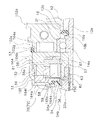
逆転防止機構50は、ロータの筒部30の内部に配置されている。逆転防止機構50は、図3及び図4に示すように、内輪57が遊転するローラ型のワンウェイクラッチ組立体51と、カバー部材52と、第1シール部材53と、第2シール部材54と、切換機構55と、を有している。
<Reverse rotation prevention mechanism>
The reverse
ワンウェイクラッチ組立体51は、取付部2eに取付可能な円形のケース部材56と、ケース部材56に収納される内輪57、外輪58、複数の転動体59、複数のばね部材60(図4参照)及びばね保持部材61と、を有している。ワンウェイクラッチ組立体51は、切換機構55によって、作動状態(逆転禁止状態)と非作動状態(逆転許可状態)とに切り換え可能である。ワンウェイクラッチ組立体51は、ピニオンギア12のギア歯12dよりも前方に配置されている。
The one-way
ケース部材56は、リールボディ2aの取付部2eに固定されている。ケース部材56には、上述した各部が収納される概ね円形の収納空間56aが形成される。収納空間56aの内周面には、外輪58が回転不能に係合する複数(例えば、6個)の凹部56bが周方向に間隔を隔てて形成される。また、ケース部材56には、スプール軸方向に貫通して形成された複数(例えば3つ)のねじ挿通孔56c及び複数(例えば3つ)の第2雌ねじ部56dが周方向に間隔を隔てて交互に配置される。ケース部材56の外周面は、ワンウェイクラッチ組立体51の外周部51aを規定する。
The
内輪57は、ピニオンギア12に回転自在に装着され転動体59に接触する内輪本体62と、内輪本体62をピニオンギア12に回転不能に連結するための連結部材63とを有している。内輪本体62は、大径部62aと小径部62bとを有する段付き筒状部材である。大径部62aには、連結部材63を回転不能に係止するための係止凹部62cが形成されている。係止凹部62cは、正面から見て略矩形の空間である。大径部62aの外周面は転動体59が転動する精密加工された円形の転動面62dである。小径部62bの中心部には、円形の装着孔62eが形成されている。装着孔62eは、ピニオンギア12の面取り部12bが形成されていない外周面に装着され、ピニオンギア12に芯出しされた状態で装着されている。
The
ここでは、転動体59に接触する内輪本体62と連結部材63とに内輪57を分け、内輪本体62をピニオンギア12に回転自在に装着し、内輪本体62とピニオンギア12とに回転不能に係止された連結部材63でピニオンギア12と内輪本体62とを連結しているので、内輪本体62に簡単に高精度な円形の孔を形成することができる。このため、転動体59に接触する内輪本体62をピニオンギア12に高精度に装着することができ、ワンウェイクラッチ組立体51の内輪57とピニオンギア12とのがたつきを抑えることができる。
Here, the
外輪58は、外周部に複数の突出部58aを有しており、これらの突出部58aはケース部材56に設けられた凹部56bに係合している。これにより、外輪58は、ケース部材56に回転不能に設けられる。ここで、突出部58aの先端とケース部材56の凹部56bとの間には径方向の隙間が比較的広く確保され、一方、回転方向へは隙間が狭くなっている。このため、外輪58は、内輪57及び転動体59によって自動調芯されるようになっている。また、外輪58の内周面には転動体59に対してくさび効果を発揮するための湾曲したカム面58bが形成されている。外輪58の軸方向の幅は、転動体59の軸方向の長さよりも短い。
The
複数(例えば5個)の転動体59は、円筒コロ形状である。転動体59は、ばね保持部材61によって保持される。
The plurality of (for example, five) rolling
ばね保持部材61は、ケース部材56に回動自在に装着される。ばね保持部材61は、複数のばね部材60を周方向に間隔を隔てて保持するものである。ばね部材60は、複数の転動体59を周方向に間隔を隔てて保持する。また、ばね保持部材61は、逆転許可位置と、逆転許可位置とスプール軸回りの異なる位置に設けられる逆転禁止位置と、に切換機構55によって回動させられる。ばね保持部材61は、周方向に間隔を隔てて配置され前方に突出する複数(例えば5つ)の保持突起61aを有する。ばね部材60は、保持突起61aに形成された保持穴61bに保持される。転動体59は、ばね部材60と保持突起61aとの間に保持される。
The
カバー部材52は、第1カバー部64と、第2カバー部65と、を有している。第1カバー部64は、ワンウェイクラッチ組立体51の前面を覆いかつピニオンギア12が貫通可能なリング状の底部64a、及び底部64aの外周部に一体形成され、ワンウェイクラッチ組立体51の外周部51aと取付部2eの外周部とを覆う筒状部64b、を有する、例えば金属又は合成樹脂等の剛体製の部材である。底部64aは、外輪58の前面に配置され転動体59を抜け止めする。底部64aには、ケース部材56のねじ挿通孔56c及び第2雌ねじ部56dと同じ周方向位置に設けられる複数(例えば6つ)の第1ねじ挿通孔64cが形成される。また、底部64aには、第2カバー部65との間に第2シール部材54を装着するため及び第2カバー部65を第1カバー部64と同芯に配置するための環状の突起部64dが形成されている。筒状部64bの後端部の内周面には、第1シール部材53が配置される配置凹部64e(図3参照)が形成されている。配置凹部64eは、カバー部材52をワンウェイクラッチ組立体51に固定したときに、取付部2eに形成された環状溝2gに対向して配置される。この配置凹部64eと環状溝2gの間に第1シール部材53が配置される。
The
第2カバー部65は、段付きリング状の部材である。第2カバー部65は、第1カバー部64の底部64aの前面に設けられる。第2カバー部65は、内周部において第1カバー部64との間で第2シール部材54の外周部を挟持する。第2カバー部65の外周側には、第1ねじ挿通孔に対向可能な複数(例えば6つ)の第2ねじ挿通孔65a(図4参照)が周方向に間隔を隔てて形成されている。第2カバー部65の後面65b(図3参照)には、突起部64dに嵌合する嵌合部65cが形成されている。突起部64dに嵌合部65cが嵌合することによって第2カバー部65が第1カバー部64に芯出しされる。このように、カバー部材52を第1カバー部64と第2カバー部65とによって構成し、内周部に第2シール部材54を挟持するように構成したので、第2シール部材54を装着しやすくなる。
The
第1シール部材53は、カバー部材52の筒状部64b内周面と取付部2eの外周面との隙間をシールするために設けられる。第1シール部材53は、例えば、NBR(ニトリルブタジエンゴム)製又はシリコーンゴム製等の合成ゴム製のOリングである。第1シール部材53は、環状溝2gに装着され、外周部がカバー部材52の配置凹部64eに接触する。
The
第2シール部材54は、例えば、NBR(ニトリルブタジエンゴム)製又はシリコーンゴム製等の合成ゴム製のリング状の部材である。第2シール部材54は、カバー部材52の底部の内周部に装着されるリング部54aと、リング部54aと一体形成され装着部33aの間隙部材36の外周面に接触する先細りのリップ部54bと、を有する。リップ部54bは、リング部54aから前方に向かって傾斜している。
The
切換機構55は、ワンウェイクラッチ組立体51を作動状態と非作動状態とに切り替えるために設けられる。切換機構55は、切換レバー66と、切換板67と、を有している。切換レバー66は、図2に示すようにリールボディ2aの下部にスプール軸15と平行な軸回りに逆転許可位置と逆転禁止位置とに揺動可能に設けられる。切換板67は、図3及び図4に示すように、ケース部材56に回動自在に装着される。ばね保持部材61に一体回動可能に係合する係合孔67aと、切換レバー66に係合する係合部67bは、切換レバー66の揺動に連動して切換板67を回動させるために設けられる。切換板67は、切換レバー66の逆転禁止位置と逆転許可位置との揺動に連動して逆転禁止位置と逆転許可位置とにスプール軸回りに回動する。この回動がばね保持部材61に伝達され、ワンウェイクラッチ組立体51が作動状態と非作動状態とに切り換えられる。
The
また、逆転防止機構50は、ケース部材56及びカバー部材52を取付部2eの前面に固定するための第1固定部材としての複数本(例えば3本)の第1ねじ部材70と、カバー部材52をケース部材56に固定する第2固定部材としての複数本(例えば3本)の第2ねじ部材72と、をさらに有する。第1ねじ部材70は、第2ねじ部材72よりも長さが長い。第1ねじ部材70は、第2カバー部65の第2ねじ挿通孔65a、第1カバー部64の第1ねじ挿通孔64c、及びケース部材56のねじ挿通孔56cを貫通して取付部2eの第1雌ねじ部2hにねじ込まれる。第2ねじ部材72は、第2カバー部65の第2ねじ挿通孔65a及び第1カバー部64の第1ねじ挿通孔64cを貫通してケース部材56の第2雌ねじ部56dにねじ込まれる。第2ねじ部材72は、カバー部材52と内輪57を除くワンウェイクラッチ組立体51と、をユニット化するために用いられる。第1ねじ部材70は、ユニット化されたワンウェイクラッチ組立体51及びカバー部材52を取付部2eに取り付けられるために設けられる。第1ねじ部材70及び第2ねじ部材72は、例えば、丸頭のボルト部材である。
Moreover,
このように構成された逆転防止機構50をリール本体2に組み込む際には、予め、ばね部材60をばね保持部材61の保持穴61bに装着し、さらに転動体59をばね保持部材61に保持させる。また、取付部2eの環状溝2gに第1シール部材53を装着しておく。
When the reverse
この状態で、切換板67、ばね保持部材61、外輪58をケース部材56の収納空間56aに収納する。次に、第1カバー部64の突起部64dの内周面に第2シール部材54を装着し、第2カバー部65を第1カバー部64に装着する。このとき、第1ねじ挿通孔64cと第2ねじ挿通孔65aとの周方向位置に合わせておく。なお、第1カバー部64と第2カバー部65の周方向位置が合うように、第1カバー部64と第2カバー部65とに周方向位置の位置決め手段を例えば凹凸嵌合等の適宜の位置決め構造によって設けてもよい。
In this state, the switching
これらの作業が終わると、第1カバー部64に第2カバー部65が装着されたカバー部材52を、ケース部材56の外周面に嵌合させ、第2ねじ部材72をケース部材56にねじ込むことによって、内輪57を除くワンウェイクラッチ組立体51とカバー部材52とをユニット化する。ユニット化が終わると、第1ねじ部材70をユニット化されたカバー部材52及びワンウェイクラッチ組立体51を貫通させて取付部2eにねじ込み、カバー部材52及びワンウェイクラッチ組立体51をリール本体2に固定する。
When these operations are completed, the
なお、内輪57は、ピニオンギア12がリール本体2に装着された後にピニオンギア12の面取り部12bに装着される。
The
<スプール>
スプール4は、リールボディ2aに前後往復移動可能に装着され、ロータ3によって外周に釣り糸が巻き付けられる。スプール4は、図2に示すように、ロータ3の第1ロータアーム31と第2ロータアーム32との間に配置されている。スプール4は、2つの軸受81,82によりスプール軸15に回転自在に装着される。スプール4は、糸巻胴部4aと、糸巻胴部と一体形成された大径のスカート部4bと、糸巻胴部の前部に設けられた大径のフランジ部4cと、を有している。糸巻胴部4aの内部にはドラグ機構80が配置されている。スプール4は、スプール軸15とドラグ機構80を介して摩擦係合している。これにより、スプール4はドラグ機構80が作動しない状態では、スプール軸15に対して回転しない。
<Spool>
The
このように構成されたスピニングリール100では、スピニングリール100を洗浄するとき等に、ロータ3の筒部30の後端部から筒部30の内部に液体が浸入することがある。このとき、浸入した液体は、逆転防止機構50の内部に浸入しようとする。しかし、ワンウェイクラッチ組立体51にカバー部材52が設けられ、カバー部材52に第1シール部材53と第2シール部材54とが設けられているため、カバー部材52の底部及び筒状部からの液体の浸入が阻止される。このため、ワンウェイクラッチ組立体51とリール本体2との間からの液体の浸入をさらに確実に防止できるようにすることになる。
In the
<他の実施形態>
以上、本発明の一実施形態について説明したが、本発明は上記実施形態に限定されるものではなく、発明の要旨を逸脱しない範囲で種々の変更が可能である。特に、本明細書に書かれた複数の実施形態及び変形例は必要に応じて任意に組合せ可能である。
<Other embodiments>
As mentioned above, although one Embodiment of this invention was described, this invention is not limited to the said embodiment, A various change is possible in the range which does not deviate from the summary of invention. In particular, a plurality of embodiments and modifications described in this specification can be arbitrarily combined as necessary.
(a)前記実施形態では、逆転防止機構50のカバー部材52において、第1カバー部64の前面に第2カバー部65を配置したが、図5では、逆転防止機構150のカバー部材152において、第1カバー部164の後面に第2カバー部165が設けられる。すなわち、第1カバー部164は、外輪の前面に隙間をあけて配置された底部164a及び筒状部164bを有する。第2カバー部165は、底部164aと外輪58との隙間に配置され、転動体59を抜け止めし、内周部で第1カバー部164との間で第2シール部材54の外周部を挟持する。なお、第2カバー部165が第1カバー部164の底部164aの後面に配置されるため、突起部164dは、第2カバー部165に設けられ、嵌合部165cは、第1カバー部164の底部164aの後面164fに設けられる。第2シール部材54は、突起部164dの内周部に設けられる。
(A) In the above embodiment, in the
また、リールボディ102aの取付部102eに形成される環状溝102gは、取付部102eの前面につながるように配置される。したがって、第1カバー部164の筒状部164bの軸方向長さは筒状部64bよりも短い。第1シール部材53は、ワンウェイクラッチ組立体51の後面、すなわちケース部材56の後面に接触するOリングである。その他の構成は、前記実施形態と同様なため、同じ符号を図5に付して説明を省略する。
Further, the
(b)前記実施形態では、第1シール部材にOリングを用いたが第1シール部材にリップ付きのシール部材等のOリング以外の環状のシール部材を用いてもよい。また、第2シール部材にOリング等の他の形態のシール部材を用いてもよい。 (B) In the said embodiment, although the O-ring was used for the 1st seal member, you may use cyclic | annular seal members other than O-rings, such as a seal member with a lip, for the 1st seal member. Moreover, you may use the sealing member of other forms, such as an O-ring, for a 2nd sealing member.
(c)前記実施形態では、カバー部材52を第1カバー部64と第2カバー部65とによって構成したが、本発明はこれに限定されない。カバー部材は、有底筒状の一つの部材で構成してもよい。
(C) In the above embodiment, the
(d)前記実施形態では、第1カバー部64の筒状部64bが取付部2eの一部を覆っているが全部を覆ってもよい。この場合、第1シール部材として、取付部2eの段差部分に円板状の第1シール部材を装着し、筒状部の後端面と、取付部2eの環状の段差面との間でシールするようにしてもよい。
(D) In the said embodiment, although the
(e)前記実施形態では、ケース部材56と外輪58とを別部材で構成したが、本発明はこれに限定されない。ケース部材と外輪とを一体形成してもよい。この場合、同じ金属又は合成樹脂製の溶融された素材を型に入れて一体形成してもよく、金属製の外輪を金属製又は合成樹脂製のケース部材に例えばインサート成形によって一体形成してもよい。
(E) In the above described embodiment, the the
(f)前記実施形態では、ロータ3の装着部33aは間隙部材36を有し、第2シール部材54を間隙部材36に接触させているが、本発明はこれに限定されない。例えば、装着部33aに間隙部材を設けなくてもよい。この場合、第2シール部材を装着部33aに直接接触させてもよい。
(F) In the above embodiment, the mounting
<特徴>
上記実施形態は、下記のように表現可能である。
<Features>
The above embodiment can be expressed as follows.
(A)スピニングリール100は、釣り糸を前方に繰り出すリールである。スピニングリール100は、ハンドル1と、リール本体2と、ロータ3と、スプール4と、ロータ駆動機構5と、逆転防止機構50と、を備える。リール本体2は、釣り竿を装着可能な竿装着部2bと、前部に設けられる円形の取付部2e(又は102e)と、を有し、ハンドル1を回転自在に支持する。ロータ3は、筒状の装着部33aを有し、リール本体2に回転自在に装着される。スプール4は、リール本体2に前後往復移動可能に装着され、ロータ3によって釣り糸が巻き付けられる。ロータ駆動機構5は、フェースギア歯を有し、ハンドル1の回転に連動して回転する駆動ギア11、及びロータ3の装着部33aが前部12aに一体回転可能に連結され駆動ギア11にかみ合う筒状のピニオンギア12、を有する。逆転防止機構50は、ロータ3の糸繰り出し方向の回転を禁止する。逆転防止機構50は、ワンウェイクラッチ組立体51と、カバー部材52(又は152)と、第1シール部材53と、第2シール部材54と、を備える。ワンウェイクラッチ組立体51は、リール本体2の取付部2eに着脱可能に取り付けられる内輪遊転型のものである。カバー部材52は、ワンウェイクラッチ組立体51の前面を覆いかつピニオンギア12が貫通可能なリング状の底部64a(又は164a)、及び底部64a(又は164a)の外周部に一体形成され、ワンウェイクラッチ組立体51の外周部51aと取付部2e(又は102e)の外周部とを覆う筒状部64b(又は164b)、を有する剛体製である。第1シール部材53は、取付部2e(又は102e)と筒状部64b(又は164b)との隙間をシールする。第2シール部材54は、ロータ3の装着部33aとカバー部材52(又は152)の底部64a(又は164a)との隙間をシールする。
(A) The
このスピニングリール100では、ワンウェイクラッチ組立体51の外周部51aと取付部2eの外周部が剛体製のカバー部材52(又は152)の筒状部64b(又は164b)によって覆われるとともに、ワンウェイクラッチ組立体51の前面がカバー部材52(又は152)の底部64a(又は164a)によって覆われる。また、筒状部64b(又は164b)と取付部2e(又は102e)との間の隙間が第1シール部材53によってシールされ、ピニオンギア12に装着されるロータ3の装着部33aとカバー部材52(又は152)の底部64a(又は164a)との隙間が第2シール部材54によってシールされる。ここでは、剛体製のカバー部材52(又は152)によって取付部2e及びワンウェイクラッチ組立体51の外周部を覆うとともに、ワンウェイクラッチ組立体51の前面を覆い、第1シール部材53によって取付部2eとカバー部材52(又は152)の筒状部64bとの隙間をシールする。また、第2シール部材54によってカバー部材52(又は152)の底部64a(又は164a)とロータ3の装着部33aとの隙間をシールする。このため、カバー部材52(152)が経年劣化しにくくなり、ワンウェイクラッチ組立体51とリール本体2との間からの液体の浸入をさらに確実に防止できるようにすることになる。
In the
(B)第1シール部材53は、取付部2e(又は102e)の外周部に形成された環状溝2g(又は102g)に装着され、筒状部64b(又は164b)の内周面に接触して配置されてもよい。この場合には、第1シール部材53が環状溝2g(又は102g)に装着されるので、カバー部材52(152)を取付部2e(又は102e)に装着しやすい。
(B) The
(C)環状溝2gは、取付部2eの前面よりも後方に配置されてもよい。第1シール部材53は、環状溝に装着されるOリングである。この場合には、汎用のOリングを用いてシールできるので、シールコストを下げることができる。
(C) The
(D)ワンウェイクラッチ組立体51は、取付部2eに取付可能であり外周部51aを有する円形のケース部材56と、ピニオンギア12に一体回転可能に連結される内輪57と、ケース部材56に回転不能に設けられる外輪58と、内輪57と外輪58との間に配置された複数の転動体59と、を有してもよい。カバー部材52は、外輪58の前面に配置され転動体59を抜け止めする底部64a及び筒状部64bを有する第1カバー部64と第1カバー部64の底部64aの前面に設けられ、内周部において第1カバー部64との間で第2シール部材54の外周部を挟持するリング状の第2カバー部65と、を有する。この場合にはカバー部材52が2つの部材に分割されるので、第2シール部材54を伸縮させる必要がなくなり、第2シール部材54を装着しやすい。
(D) The one-way
(E)ワンウェイクラッチ組立体51は、取付部102eに取付可能であり外周部51aを有する円形のケース部材56と、ピニオンギア12に一体回転可能に連結される内輪57と、ケース部材56に回転不能に設けられる外輪58と、内輪57と外輪58との間に配置された複数の転動体59と、を有してもよい。カバー部材152は、外輪58の前面に隙間をあけて配置された底部164a及び筒状部164bを有する第1カバー部164と、底部164aと外輪58との隙間に配置され、転動体59を抜け止めし、内周部で第1カバー部164との間で第2シール部材54の外周部を挟持する第2カバー部165と、を有する。この場合にはカバー部材152が2つの部材に分割されるので、第2シール部材54を伸縮させる必要がなくなり、第2シール部材54を装着しやすい。
(E) one-way
(F)環状溝102gは、取付部102eの前面につながるように配置されてもよい。第1シール部材53は、筒状のワンウェイクラッチ組立体51の後面に接触するOリングである。この場合には、取付部102eの外周部と筒状部164bとの隙間に加えて取付部102eとワンウェイクラッチ組立体51との隙間も合わせてOリングによってシールできる。
(F) The
(G)第2シール部材54は、底部64a(又は164a)の内周部に装着されるリング部54aと、リング部54aと一体形成され装着部33aの外周面に接触する先細りのリップ部54bと、を有してもよい。この場合には、回転するロータの装着部に接触するリップ部の接触面積が小さくなるため、ロータの回転性能の低下を抑えることができる。
(G) The
(H)逆転防止機構は、ケース部材及びカバー部材を取付部の前面に固定するための第1固定部材をさらに有してもよい。この場合には、ワンウェイクラッチ組立体と第1カバー部材と、を第1固定部材によって一括して取付部に固定できる。 (H) The reverse rotation prevention mechanism may further include a first fixing member for fixing the case member and the cover member to the front surface of the attachment portion. In this case, the one-way clutch assembly and the first cover member can be collectively fixed to the attachment portion by the first fixing member.
(I)第1固定部材は、カバー部材及びケース部材を貫通して取付部にねじ込まれ、周方向に間隔を隔てて配置された複数の第1ねじ部材を有してもよい。この場合には、第1ねじ部材を取付部にねじ込むことによってワンウェイクラッチ及びカバー部材を取付部に固定できる。 (I) The first fixing member may include a plurality of first screw members that penetrate the cover member and the case member and are screwed into the attachment portion and arranged at intervals in the circumferential direction. In this case, the one-way clutch and the cover member can be fixed to the mounting portion by screwing the first screw member into the mounting portion.
(J)逆転防止機構は、カバー部材をケース部材に固定する第2固定部材をさらに有してもよい。この場合には、カバー部材を第2固定部材によってケース部材56に固定することができるので、カバー部材とワンウェイクラッチ組立体とをユニット化できる。このため、第1固定部材を外しても、ワンウェイクラッチ組立体がバラバラにならない。また、ワンウェイクラッチ組立体をユニット化してから第1固定部材によって取付部に取り付けることができる。
(J) The reverse rotation prevention mechanism may further include a second fixing member that fixes the cover member to the case member. In this case, since the cover member can be fixed to the
(K)第2固定部材は、カバー部材を貫通してケース部材56にねじ込まれ、第1ねじ部材の間に周方向に間隔を隔てて配置された複数の第2ねじ部材を有してもよい。この場合には、第1ねじ部材の間に配置された第2ねじ部材をケース部材にねじ込むことにより、カバー部材を含むワンウェイクラッチ組立体をユニット化できる。
(K) The second fixing member may include a plurality of second screw members that pass through the cover member and are screwed into the
1 ハンドル
2 リール本体
2b 竿装着部
2e,102e 取付部
2g,102g 環状溝
3 ロータ
4 スプール
5 ロータ駆動機構
11 駆動ギア
12 ピニオンギア
33a 装着部
50 逆転防止機構
51 ワンウェイクラッチ組立体
52 カバー部材
53 第1シール部材
54 第2シール部材
56 ケース部材
57 内輪
58 外輪
59 転動体
64,164 第1カバー部
64a,164a 底部
64b,164b 筒状部
65,165 第2カバー部
70 第1ねじ部材(第1固定部材)
72 第2ねじ部材(第2固定部材)
DESCRIPTION OF
72 Second screw member (second fixing member)
Claims (11)
ハンドルと、
釣り竿を装着可能な竿装着部と、前部に設けられる円形の取付部と、を有し、前記ハンドルを回転自在に支持するリール本体と、
筒状の装着部を有し、前記リール本体に回転自在に装着されるロータと、
前記リール本体に前後往復移動可能に装着され、前記ロータによって前記釣り糸が巻き付けられるスプールと、
前記ハンドルの回転に連動して回転する駆動ギア、及び前記ロータの前記装着部が前部に一体回転可能に連結され前記駆動ギアにかみ合う筒状のピニオンギア、を有するロータ駆動機構と、
前記ロータの糸繰り出し方向の回転を禁止する逆転防止機構と、
を備え、
前記逆転防止機構は、
前記リール本体の前記取付部に着脱可能に取り付けられる内輪遊転型のワンウェイクラッチ組立体と、
前記ワンウェイクラッチ組立体の前面を覆いかつ前記ピニオンギアが貫通可能なリング状の底部、及び前記底部の外周部に一体形成され、前記ワンウェイクラッチ組立体の外周部と前記取付部の外周部とを覆う筒状部、を含む第1カバー部と、前記底部に対向して配置された第2カバー部と、を有するカバー部材と、
前記取付部と前記筒状部との隙間をシールする第1シール部材と、
前記底部と前記第2カバー部との間で挟持され、前記底部と前記ロータの前記装着部との隙間をシールする第2シール部材と、
を有する、スピニングリール。 A spinning reel that feeds fishing line forward,
A handle,
A reel body having a rod mounting portion on which a fishing rod can be mounted, and a circular mounting portion provided at the front portion, and rotatably supporting the handle;
A rotor having a cylindrical mounting portion and rotatably mounted on the reel body;
A spool that is mounted on the reel body so as to be capable of reciprocating back and forth, and on which the fishing line is wound by the rotor;
A rotor drive mechanism having a drive gear that rotates in conjunction with rotation of the handle, and a cylindrical pinion gear that is connected to the front portion so that the mounting portion of the rotor is integrally rotatable, and meshes with the drive gear;
An anti-reverse mechanism for prohibiting rotation of the rotor in the yarn unwinding direction;
With
The reverse rotation prevention mechanism is
An inner ring idle type one-way clutch assembly removably attached to the attachment portion of the reel body;
A ring-shaped bottom portion that covers the front surface of the one-way clutch assembly and through which the pinion gear can pass, and an outer peripheral portion of the one-way clutch assembly, and an outer peripheral portion of the mounting portion are formed integrally with the outer peripheral portion of the bottom portion. A cover member having a first cover portion including a cylindrical portion to be covered, and a second cover portion disposed to face the bottom portion;
A first seal member for sealing a gap between the attachment portion and the tubular portion;
A second seal member sandwiched between the bottom portion and the second cover portion and sealing a gap between the bottom portion and the mounting portion of the rotor ;
Having a spinning reel.
前記第1シール部材は、前記環状溝に装着されるOリングである、請求項2に記載のスピニングリール。 The annular groove is arranged behind the front surface of the mounting portion,
The spinning reel according to claim 2, wherein the first seal member is an O-ring mounted in the annular groove.
前記第1カバー部の前記底部は、前記外輪の前面に配置され前記転動体を抜け止めし、
前記第2カバー部は、リング状であり、前記第1カバー部の前記底部の前面に設けられ、内周部において前記第1カバー部との間で前記第2シール部材を挟持する、請求項1から3のいずれか1項に記載のスピニングリール。 The one-way clutch assembly includes a circular case member that can be attached to the attachment portion and has the outer peripheral portion, an inner ring that is connected to the pinion gear so as to be integrally rotatable, and an outer ring that is non-rotatably provided on the case member. And a plurality of rolling elements arranged between the inner ring and the outer ring,
The bottom portion of the first cover portion is disposed on the front surface of the outer ring and prevents the rolling element from coming off ,
The second cover portion has a ring-shaped, provided on a front face of the bottom portion of the first cover portion, sandwiching the second sealing member between said first cover portion at the inner peripheral portion, claim The spinning reel according to any one of 1 to 3.
前記第1カバー部の前記底部は、前記第2カバー部の前面に配置され、
前記第2カバー部は、前記外輪の前面に配置され、前記転動体を抜け止めし、内周部で前記第1カバー部との間で前記第2シール部材を挟持する、請求項1から3のいずれか1項に記載のスピニングリール。 The one-way clutch assembly includes a circular case member that can be attached to the attachment portion and has the outer peripheral portion, an inner ring that is connected to the pinion gear so as to be integrally rotatable, and an outer ring that is non-rotatably provided on the case member. And a plurality of rolling elements arranged between the inner ring and the outer ring,
The bottom portion of the first cover portion is disposed on the front surface of the second cover portion,
The said 2nd cover part is arrange | positioned in the front surface of the said outer ring | wheel, prevents the said rolling element from falling out , and clamps the said 2nd seal member between the said 1st cover part by an inner peripheral part. The spinning reel according to any one of the above.
前記第1シール部材は、前記筒状の前記ワンウェイクラッチ組立体の後面に接触するOリングである、請求項2から5のいずれか1項に記載のスピニングリール。 The annular groove is arranged so as to be connected to the front surface of the mounting portion,
The spinning reel according to any one of claims 2 to 5, wherein the first seal member is an O-ring that contacts a rear surface of the cylindrical one-way clutch assembly.
Priority Applications (4)
| Application Number | Priority Date | Filing Date | Title |
|---|---|---|---|
| JP2013107172A JP6235238B2 (en) | 2013-05-21 | 2013-05-21 | Spinning reel |
| KR1020140022211A KR102148719B1 (en) | 2013-05-21 | 2014-02-25 | Spinning reel |
| TW103112283A TWI632850B (en) | 2013-05-21 | 2014-04-02 | Spinning reel |
| CN201410214919.0A CN104170803B (en) | 2013-05-21 | 2014-05-21 | Spinning-reel |
Applications Claiming Priority (1)
| Application Number | Priority Date | Filing Date | Title |
|---|---|---|---|
| JP2013107172A JP6235238B2 (en) | 2013-05-21 | 2013-05-21 | Spinning reel |
Publications (3)
| Publication Number | Publication Date |
|---|---|
| JP2014226070A JP2014226070A (en) | 2014-12-08 |
| JP2014226070A5 JP2014226070A5 (en) | 2016-06-30 |
| JP6235238B2 true JP6235238B2 (en) | 2017-11-22 |
Family
ID=51952377
Family Applications (1)
| Application Number | Title | Priority Date | Filing Date |
|---|---|---|---|
| JP2013107172A Active JP6235238B2 (en) | 2013-05-21 | 2013-05-21 | Spinning reel |
Country Status (3)
| Country | Link |
|---|---|
| JP (1) | JP6235238B2 (en) |
| KR (1) | KR102148719B1 (en) |
| TW (1) | TWI632850B (en) |
Families Citing this family (1)
| Publication number | Priority date | Publication date | Assignee | Title |
|---|---|---|---|---|
| JP6615057B2 (en) * | 2016-06-30 | 2019-12-04 | グローブライド株式会社 | Fishing reel |
Family Cites Families (5)
| Publication number | Priority date | Publication date | Assignee | Title |
|---|---|---|---|---|
| JP3839972B2 (en) | 1998-09-17 | 2006-11-01 | 株式会社シマノ | Spinning reel waterproof structure |
| JP4057254B2 (en) * | 2001-05-31 | 2008-03-05 | ダイワ精工株式会社 | Fishing spinning reel |
| JP5153269B2 (en) * | 2007-09-05 | 2013-02-27 | 株式会社シマノ | Roller clutch |
| JP5254885B2 (en) * | 2009-05-29 | 2013-08-07 | グローブライド株式会社 | Fishing spinning reel |
| JP5080677B2 (en) * | 2010-01-19 | 2012-11-21 | グローブライド株式会社 | Fishing spinning reel |
-
2013
- 2013-05-21 JP JP2013107172A patent/JP6235238B2/en active Active
-
2014
- 2014-02-25 KR KR1020140022211A patent/KR102148719B1/en active IP Right Grant
- 2014-04-02 TW TW103112283A patent/TWI632850B/en active
Also Published As
| Publication number | Publication date |
|---|---|
| TWI632850B (en) | 2018-08-21 |
| KR20140136862A (en) | 2014-12-01 |
| TW201509299A (en) | 2015-03-16 |
| KR102148719B1 (en) | 2020-08-27 |
| CN104170803A (en) | 2014-12-03 |
| JP2014226070A (en) | 2014-12-08 |
Similar Documents
| Publication | Publication Date | Title |
|---|---|---|
| JP2014226071A5 (en) | ||
| JP2014226071A (en) | Spinning reel | |
| US9091350B2 (en) | Spinning reel waterproofing member and spinning reel using the same | |
| JP5961407B2 (en) | Spinning reel waterproofing member and spinning reel using the same | |
| JP5961399B2 (en) | Spinning reel waterproofing material | |
| KR102002854B1 (en) | Handle assembly for spinning reel | |
| JP6235238B2 (en) | Spinning reel | |
| JP3840009B2 (en) | Spinning reel | |
| EP3289870B1 (en) | Rotor drive unit waterproof structure and spinning reel | |
| JP2014226070A5 (en) | ||
| JP2010279259A5 (en) | ||
| JP2003111536A (en) | Tightening structure for fishing component | |
| JP5401411B2 (en) | Fishing spinning reel | |
| JP6046481B2 (en) | Spinning reel and spinning reel spool | |
| KR20160030833A (en) | Line Roller | |
| JP2014121279A5 (en) | ||
| JP4964709B2 (en) | Fishing reel | |
| JP6247138B2 (en) | Fishing spinning reel | |
| JP6110128B2 (en) | Spinning reel and spinning reel spool | |
| JP6251105B2 (en) | Fishing spinning reel | |
| CN104170803B (en) | Spinning-reel | |
| JP2007209217A (en) | Spinning reel for fishing | |
| JP2010081836A (en) | Nut assembly of spinning reel | |
| JP2009022167A (en) | Spinning reel rotor | |
| JP2010166846A (en) | Spinning reel |
Legal Events
| Date | Code | Title | Description |
|---|---|---|---|
| A521 | Request for written amendment filed |
Free format text: JAPANESE INTERMEDIATE CODE: A523 Effective date: 20160516 |
|
| A621 | Written request for application examination |
Free format text: JAPANESE INTERMEDIATE CODE: A621 Effective date: 20160516 |
|
| A977 | Report on retrieval |
Free format text: JAPANESE INTERMEDIATE CODE: A971007 Effective date: 20170224 |
|
| A131 | Notification of reasons for refusal |
Free format text: JAPANESE INTERMEDIATE CODE: A131 Effective date: 20170314 |
|
| A521 | Request for written amendment filed |
Free format text: JAPANESE INTERMEDIATE CODE: A523 Effective date: 20170413 |
|
| A131 | Notification of reasons for refusal |
Free format text: JAPANESE INTERMEDIATE CODE: A131 Effective date: 20170912 |
|
| A521 | Request for written amendment filed |
Free format text: JAPANESE INTERMEDIATE CODE: A523 Effective date: 20171004 |
|
| TRDD | Decision of grant or rejection written | ||
| A01 | Written decision to grant a patent or to grant a registration (utility model) |
Free format text: JAPANESE INTERMEDIATE CODE: A01 Effective date: 20171017 |
|
| A61 | First payment of annual fees (during grant procedure) |
Free format text: JAPANESE INTERMEDIATE CODE: A61 Effective date: 20171026 |
|
| R150 | Certificate of patent or registration of utility model |
Ref document number: 6235238 Country of ref document: JP Free format text: JAPANESE INTERMEDIATE CODE: R150 |
|
| R250 | Receipt of annual fees |
Free format text: JAPANESE INTERMEDIATE CODE: R250 |
|
| R250 | Receipt of annual fees |
Free format text: JAPANESE INTERMEDIATE CODE: R250 |
|
| R250 | Receipt of annual fees |
Free format text: JAPANESE INTERMEDIATE CODE: R250 |
|
| R250 | Receipt of annual fees |
Free format text: JAPANESE INTERMEDIATE CODE: R250 |