JP2014226071A - Spinning reel - Google Patents
Spinning reel Download PDFInfo
- Publication number
- JP2014226071A JP2014226071A JP2013107173A JP2013107173A JP2014226071A JP 2014226071 A JP2014226071 A JP 2014226071A JP 2013107173 A JP2013107173 A JP 2013107173A JP 2013107173 A JP2013107173 A JP 2013107173A JP 2014226071 A JP2014226071 A JP 2014226071A
- Authority
- JP
- Japan
- Prior art keywords
- way clutch
- clutch assembly
- rotor
- pinion gear
- seal member
- Prior art date
- Legal status (The legal status is an assumption and is not a legal conclusion. Google has not performed a legal analysis and makes no representation as to the accuracy of the status listed.)
- Pending
Links
Images

Classifications
-
- A—HUMAN NECESSITIES
- A01—AGRICULTURE; FORESTRY; ANIMAL HUSBANDRY; HUNTING; TRAPPING; FISHING
- A01K—ANIMAL HUSBANDRY; CARE OF BIRDS, FISHES, INSECTS; FISHING; REARING OR BREEDING ANIMALS, NOT OTHERWISE PROVIDED FOR; NEW BREEDS OF ANIMALS
- A01K89/00—Reels
- A01K89/01—Reels with pick-up, i.e. with the guiding member rotating and the spool not rotating during normal retrieval of the line
- A01K89/0117—Anti-reverse mechanisms
-
- A—HUMAN NECESSITIES
- A01—AGRICULTURE; FORESTRY; ANIMAL HUSBANDRY; HUNTING; TRAPPING; FISHING
- A01K—ANIMAL HUSBANDRY; CARE OF BIRDS, FISHES, INSECTS; FISHING; REARING OR BREEDING ANIMALS, NOT OTHERWISE PROVIDED FOR; NEW BREEDS OF ANIMALS
- A01K89/00—Reels
- A01K89/01—Reels with pick-up, i.e. with the guiding member rotating and the spool not rotating during normal retrieval of the line
Landscapes
- Life Sciences & Earth Sciences (AREA)
- Environmental Sciences (AREA)
- Animal Husbandry (AREA)
- Biodiversity & Conservation Biology (AREA)
Abstract
Description
本発明は、釣り用リール、特に、釣り糸を前方に繰り出すスピニングリールに関する。 The present invention relates to a fishing reel, and more particularly to a spinning reel that feeds a fishing line forward.
スピニングリールは、ハンドルと、ハンドルを回転自在に支持するリール本体と、ロータと、スプールと、ロータ駆動機構と、逆転防止機構と、を備えている。ロータは、筒状の装着部を有し、リール本体に回転自在に装着される。スプールは、ロータによって釣り糸が巻き付けられる。ロータ駆動機構は、ハンドルの回転によって回転する駆動ギアと、駆動ギアに噛み合いロータを回転させるピニオンギアと、を有している。リール本体の前部には、逆転防止機構を取り付けるための円形の取付部が形成される。逆転防止機構は、ピニオンギアを介してロータの糸繰り出し方向の回転を禁止する。逆転防止機構は、ローラ型のワンウェイクラッチ組立体を有している。ワンウェイクラッチ組立体は、ねじ部材によってリール本体の取付部に固定される。 The spinning reel includes a handle, a reel body that rotatably supports the handle, a rotor, a spool, a rotor drive mechanism, and a reverse rotation prevention mechanism. The rotor has a cylindrical mounting portion and is rotatably mounted on the reel body. The spool is wound with a fishing line by a rotor. The rotor drive mechanism has a drive gear that rotates by rotation of the handle and a pinion gear that meshes with the drive gear and rotates the rotor. A circular attachment portion for attaching the reverse rotation prevention mechanism is formed at the front portion of the reel body. The reverse rotation prevention mechanism prohibits rotation of the rotor in the yarn unwinding direction via the pinion gear. The reverse rotation prevention mechanism has a roller type one-way clutch assembly. The one-way clutch assembly is fixed to the mounting portion of the reel body by a screw member.
このような構成の逆転防止機構を有するスピニングリールにおいて、逆転防止機構と取付部との隙間から液体が侵入するのを防止するために、ワンウェイクラッチ組立体の外周部面及びリール本体の取付部の外周面を覆う合成ゴム製の薄肉筒状のシールリングを有するものが知られている(例えば、特許文献1参照)。これにより、ワンウェイクラッチ組立体の外周面及びワンウェイクラッチ組立体とリール本体の取付部との隙間から液体がワンウェイクラッチ組立体の内部及びリール本体の内部に侵入するのを防止できる。 In the spinning reel having the reverse rotation prevention mechanism having such a configuration, in order to prevent liquid from entering through the gap between the reverse rotation prevention mechanism and the attachment portion, the outer peripheral surface of the one-way clutch assembly and the attachment portion of the reel body are provided. One having a thin cylindrical seal ring made of synthetic rubber covering the outer peripheral surface is known (see, for example, Patent Document 1). Thus, it is possible to prevent liquid from entering the inside of the one-way clutch assembly and the inside of the reel body from the outer peripheral surface of the one-way clutch assembly and the gap between the one-way clutch assembly and the mounting portion of the reel body.
従来のスピニングリールでは、ロータ内部からリール本体の内部への液体の侵入を防止できる。しかし、リール本体の内部に侵入した液体及びリール本体内部に塗布されたグリース等の異物がリール本体から逆転防止機構に侵入するおそれがある。液体が逆転防止機構に侵入すると、ワンウェイクラッチ組立体が腐食したり、海水から析出した塩がローラに噛んだりしてワンウェイクラッチ組立体が動作不良を起こすおそれがある。また、グリースが逆転防止機構に侵入すると、ワンウェイクラッチ組立体のローラが滑って逆転禁止状態が不安定になるおそれがある。 In a conventional spinning reel, liquid can be prevented from entering the inside of the reel body from the inside of the rotor. However, foreign matter such as liquid that has entered the inside of the reel body and grease applied to the inside of the reel body may enter the reverse rotation prevention mechanism from the reel body. If the liquid enters the reverse rotation prevention mechanism, the one-way clutch assembly may be corroded, or salt deposited from seawater may bite into the roller, causing the one-way clutch assembly to malfunction. In addition, if grease enters the reverse rotation prevention mechanism, the roller of the one-way clutch assembly may slip and the reverse rotation prohibition state may become unstable.
本発明の課題は、スピニングリールにおいて、リール本体の内部から逆転防止機構への異物の侵入を抑えることにある。 An object of the present invention is to suppress entry of foreign matter from the inside of a reel body into a reverse rotation prevention mechanism in a spinning reel.
本発明に係るスピニングリールは、釣り糸を前方に繰り出すリールである。スピニングリールは、ハンドルと、リール本体と、ロータと、スプールと、ロータ駆動機構と、逆転防止機構と、を備えている。リール本体は、釣り竿を装着可能な竿装着部と、前部に設けられ中心に前後方向に配置された貫通孔を有する円形の取付部と、を有し、ハンドルを回転自在に支持する。ロータは、筒状の装着部を有し、リール本体に回転自在に装着される。スプールは、リール本体に前後往復移動可能に装着され、ロータによって釣り糸が巻き付けられる。ロータ駆動機構は、駆動ギアと筒状のピニオンギアと、を有する。駆動ギアは、フェースギア歯を有し、ハンドルの回転に連動して回転する。ピニオンギアは、ロータの装着部が前部に一体回転可能に連結され、貫通孔を貫通して前後方向に配置され、駆動ギアにかみ合う。逆転防止機構は、リール本体の取付部に着脱可能に取り付けられる内輪遊転型のワンウェイクラッチ組立体を有し、ロータの糸繰り出し方向の回転を禁止する。ロータ駆動機構は、ワンウェイクラッチ組立体よりも後方でピニオンギアと貫通孔の隙間をシールするシール部材を有する。 The spinning reel according to the present invention is a reel that feeds a fishing line forward. The spinning reel includes a handle, a reel body, a rotor, a spool, a rotor drive mechanism, and a reverse rotation prevention mechanism. The reel body includes a rod mounting portion on which a fishing rod can be mounted, and a circular mounting portion having a through-hole provided at the front portion and disposed in the front-rear direction at the center, and rotatably supports the handle. The rotor has a cylindrical mounting portion and is rotatably mounted on the reel body. The spool is attached to the reel body so as to be movable back and forth, and a fishing line is wound around the rotor. The rotor drive mechanism has a drive gear and a cylindrical pinion gear. The drive gear has face gear teeth and rotates in conjunction with the rotation of the handle. The pinion gear is connected to the front portion of the rotor mounting portion so as to be integrally rotatable, is disposed in the front-rear direction through the through hole, and meshes with the drive gear. The anti-reverse mechanism includes an inner ring idle type one-way clutch assembly that is detachably attached to the attachment portion of the reel body, and prohibits rotation of the rotor in the yarn unwinding direction. The rotor drive mechanism has a seal member that seals the gap between the pinion gear and the through hole behind the one-way clutch assembly.
このスピニングリールでは、ロータ駆動機構において、ワンウェイクラッチ組立体よりも後方でピニオンギアとピニオンギアが配置される貫通孔との隙間がシール部材によってシールされる。このため、リール本体の内部から逆転防止機構への異物の侵入を抑えることができる。また、逆転防止機構からリール本体の内部への異物の侵入も抑えることができる。 In this spinning reel, in the rotor drive mechanism, the gap between the pinion gear and the through hole in which the pinion gear is disposed is sealed behind the one-way clutch assembly by the seal member. For this reason, it is possible to suppress entry of foreign matter from the inside of the reel body into the reverse rotation prevention mechanism. Further, it is possible to suppress the entry of foreign matter from the reverse rotation prevention mechanism into the reel body.
シール部材は、ピニオンギアの外周部に形成された環状の装着溝に装着され、貫通孔の内周面に接触して配置されてもよい。この場合には、ピニオンギアとともにシール部材が回転するので、異物が遠心力によって飛散し、異物がさらに逆転防止機構側に侵入しにくい。 The seal member may be mounted in an annular mounting groove formed on the outer peripheral portion of the pinion gear, and may be disposed in contact with the inner peripheral surface of the through hole. In this case, since the seal member rotates together with the pinion gear, the foreign matter is scattered by the centrifugal force, and the foreign matter is less likely to enter the reverse rotation prevention mechanism side.
シール部材は、装着溝に装着されるリング部と、リング部と一体形成され、貫通孔の内周面に接触する先細りのリップ部と、を有してもよい。この場合には、シール部材の貫通孔の内周面に接触する部分が先細りのリップ部であるので、シール部材が回転しても摺動抵抗が小さくなり、ピニオンギアの回転性能の低下を抑えることができる。 The seal member may include a ring portion that is attached to the attachment groove, and a tapered lip portion that is integrally formed with the ring portion and contacts the inner peripheral surface of the through hole. In this case, since the portion that contacts the inner peripheral surface of the through hole of the seal member is a tapered lip portion, the sliding resistance is reduced even when the seal member rotates, and the deterioration of the rotation performance of the pinion gear is suppressed. be able to.
ピニオンギアは、ワンウェイクラッチ組立体よりも後方に配置され、フェースギア歯にかみ合うギア歯を有し、ギア歯の両側で前後に間隔を隔てて配置される前軸受と後軸受を介してリール本体に回転自在に支持されてもよい。シール部材は、前軸受よりも後方に配置される。この場合には、前軸受への異物の侵入も抑えることができる。 The pinion gear is disposed rearward of the one-way clutch assembly, has gear teeth that mesh with the face gear teeth, and the reel body via a front bearing and a rear bearing that are spaced apart from each other on both sides of the gear teeth. It may be supported so as to be freely rotatable. The seal member is disposed behind the front bearing. In this case, entry of foreign matter into the front bearing can also be suppressed.
リップ部は、前軸受側に傾斜していてもよい。この場合には、シール部材をピニオンギアに装着した状態でピニオンギアをリール本体の前部から装着してもリップ部が倒れにくくなる。このため、リップ部を変形させることなくピニオンギアをリール本体に装着できる。 The lip portion may be inclined toward the front bearing side. In this case, even if the pinion gear is mounted from the front portion of the reel body in a state where the seal member is mounted on the pinion gear, the lip portion is unlikely to fall down. For this reason, the pinion gear can be mounted on the reel body without deforming the lip portion.
逆転防止機構は、ワンウェイクラッチ組立体の前面を覆いかつピニオンギアが貫通可能なリング状の底部、及びワンウェイクラッチ組立体の外周部と取付部の外周部とを覆う筒状部、を有する防水用のカバー部材をさらに有してもよい。この場合には、ワンウェイクラッチ組立体を取付部の前面に取り付けても取付部とワンウェイクラッチ組立体との境界部分からワンウェイクラッチ組立体の内部に異物が侵入しにくくなる。 The reverse rotation prevention mechanism has a ring-shaped bottom portion that covers the front surface of the one-way clutch assembly and through which the pinion gear can pass, and a cylindrical portion that covers the outer peripheral portion of the one-way clutch assembly and the outer peripheral portion of the mounting portion. The cover member may be further included. In this case, even if the one-way clutch assembly is attached to the front surface of the attachment portion, foreign matter does not easily enter the inside of the one-way clutch assembly from the boundary portion between the attachment portion and the one-way clutch assembly.
ワンウェイクラッチ組立体は、取付部に取付可能でありワンウェイクラッチ組立体の外周部を有する円形のケース部材と、ピニオンギアに一体回転可能に連結された内輪と、ケース部材に回転不能に設けられる外輪と、内輪と外輪との間に配置された複数の転動体と、を有してもよい。この場合には、ケース部材の内部に内輪、外輪及び転動体を配置できるので、ワンウェイクラッチ組立体をユニット化できる。このため、予めワンウェイクラッチ組立体を組み立てておくことができ、ワンウェイクラッチ組立体のリール本体への組み込みが容易である。 The one-way clutch assembly includes a circular case member that can be attached to the attachment portion and has an outer peripheral portion of the one-way clutch assembly, an inner ring that is connected to the pinion gear so as to be integrally rotatable, and an outer ring that is provided on the case member so as not to rotate. And a plurality of rolling elements arranged between the inner ring and the outer ring. In this case, since the inner ring, the outer ring, and the rolling element can be disposed inside the case member, the one-way clutch assembly can be unitized. For this reason, the one-way clutch assembly can be assembled in advance, and the one-way clutch assembly can be easily incorporated into the reel body.
逆転防止機構は、取付部と筒状部の隙間をシールする第1シール部材と、ロータの装着部とカバー部材の底部の隙間をシールする第2シール部材と、をさらに有してもよい。この場合には、カバー部材の筒状部と取付部との隙間及びカバー部材とロータの装着部との隙間をシールできるので、ワンウェイクラッチ組立体の内部への異物の侵入をさらに抑えることができる。 The reverse rotation prevention mechanism may further include a first seal member that seals a gap between the attachment portion and the cylindrical portion, and a second seal member that seals a gap between the mounting portion of the rotor and the bottom portion of the cover member. In this case, since the clearance between the cylindrical portion of the cover member and the mounting portion and the clearance between the cover member and the mounting portion of the rotor can be sealed, entry of foreign matter into the one-way clutch assembly can be further suppressed. .
第1シール部材は、取付部の外周部に形成された環状溝に装着され、筒状部の内周面に接触して配置される。この場合には、第1シール部材が環状溝に装着されるので、カバー部材を取付部に装着しやすい。 The first seal member is mounted in an annular groove formed on the outer peripheral portion of the attachment portion, and is disposed in contact with the inner peripheral surface of the cylindrical portion. In this case, since the first seal member is attached to the annular groove, it is easy to attach the cover member to the attachment portion.
逆転防止機構は、カバー部材及びケース部材を貫通して取付部にねじ込まれ、周方向に間隔を隔てて配置された複数の第1ねじ部材をさらに有してもよい。この場合には、第1ねじ部材を取付部にねじ込むことによって、ワンウェイクラッチ組立体及びカバー部材を一括して取付部に固定できる。 The reverse rotation prevention mechanism may further include a plurality of first screw members that pass through the cover member and the case member and are screwed into the attachment portion and arranged at intervals in the circumferential direction. In this case, the one-way clutch assembly and the cover member can be collectively fixed to the mounting portion by screwing the first screw member into the mounting portion.
逆転防止機構は、カバー部材を貫通してケース部材にねじ込まれる第2ねじ材をさらに有してもよい。この場合には、第2ねじ部材をケース部材にねじ込むことにより、カバー部材を含むワンウェイクラッチ組立体をユニット化できる。 The reverse rotation prevention mechanism may further include a second screw member that passes through the cover member and is screwed into the case member. In this case, the one-way clutch assembly including the cover member can be unitized by screwing the second screw member into the case member.
取付部は、先端が開口しワンウェイクラッチ組立体を収納可能な円形の収納空間を有してもよい。ワンウェイクラッチ組立体は、ピニオンギアに一体回転可能に連結された内輪と、収納空間に回転不能に設けられる外輪と、内輪と外輪との間に配置された複数の転動体と、を有する。この場合には、ワンウェイクラッチ組立体がリール本体に設けられる収納空間に収納されるので、逆転防止機構の構成が簡素化できる。 The attachment portion may have a circular storage space that is open at the tip and can store the one-way clutch assembly. The one-way clutch assembly includes an inner ring that is coupled to the pinion gear so as to be integrally rotatable, an outer ring that is non-rotatably provided in the storage space, and a plurality of rolling elements that are disposed between the inner ring and the outer ring. In this case, since the one-way clutch assembly is stored in the storage space provided in the reel body, the configuration of the reverse rotation prevention mechanism can be simplified.
逆転防止機構は、第3シール部材と抜け止め部材と、さらに有してもよい。第3シール部材は、外輪の前面で収納空間をシールする。抜け止め部材は、第3シール部材を収納空間に対して抜け止めする。この場合には、第3シール部材によって収納空間に異物が侵入しにくくなる。また、抜け止め部材によって第3シール部材及びワンウェイクラッチ組立体が収納空間から抜けなくなる。 The reverse rotation prevention mechanism may further include a third seal member and a retaining member. The third seal member seals the storage space at the front surface of the outer ring. The retaining member prevents the third seal member from coming off from the storage space. In this case, the third seal member makes it difficult for foreign matter to enter the storage space. Further, the third sealing member and the one-way clutch assembly are prevented from coming out of the storage space by the retaining member.
本発明によれば、ワンウェイクラッチ組立体よりも後方でピニオンギアとピニオンギアが配置される貫通孔との隙間がシール部材によってシールされる。このため、リール本体の内部から逆転防止機構への異物の侵入を抑えることができる。 According to the present invention, the gap between the pinion gear and the through hole in which the pinion gear is disposed is sealed behind the one-way clutch assembly by the seal member. For this reason, it is possible to suppress entry of foreign matter from the inside of the reel body into the reverse rotation prevention mechanism.
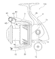
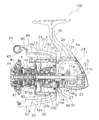
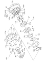
図1において、本発明の一実施形態によるスピニングリール100は、釣り糸を前方(図2左方)に繰り出すリールである。スピニングリール100は、ハンドル1と、ハンドル1を回転自在に支持するリール本体2と、ロータ3と、スプール4と、を備えている。また、スピニングリール100は、図2に示すように、ロータ駆動機構5と、オシレーティング機構6と、逆転防止機構50と、をさらに備えている。ロータ3は、リール本体2の前部に回転自在に支持されている。スプール4は、釣り糸を外周面に巻き取るものであり、ロータ3の前部に前後移動自在に配置されている。ロータ駆動機構5は、ハンドル1の回転をロータ3に伝達してロータを回転させるとともに、オシレーティング機構6に伝達する。オシレーティング機構6は、ハンドル1の回転に連動してスプール4を前後に往復移動させる。逆転防止機構50は、ロータの糸繰り出し方向の回転(逆転)を禁止する。なお、この実施形態の逆転防止機構50は、ロータの逆転の禁止する状態と、ロータの逆転を許可する状態との2つの状態に切り換え可能である。
In FIG. 1, a spinning
<ハンドル>
ハンドル1は、後述する駆動軸11aに一体回転可能に連結されるクランクアーム1aと、クランクアーム1aの先端部に回転自在に装着される把手部1bと、を有している。ハンドルは、図1に示す駆動軸11aの左側と右側のいずれにも装着可能である。なお、ここで、左右は、スピニングリール100を後方から見たときの左右である。また、上下は、図1及び図2における上下である。
<Handle>
The
<リール本体>
リール本体2は、リールボディ2aと、リールボディ2aから斜め上前方に延び、釣り竿を装着可能な竿装着部2bと、蓋部材2cと、を有している。リールボディ2aは、図2に示すように内部に機構装着用の空間2dを有しており、その空間2d内には、ロータ3をハンドル1の回転に連動して回転させるロータ駆動機構5と、スプール4を前後に移動させて釣り糸を均一に巻き取るためのオシレーティング機構6とが設けられている。空間2dは、蓋部材2cによって塞がれる。リールボディ2aは、前部に設けられ、前方に突出する円形の取付部2eを有する。取付部2eは、中心には前後方向に配置された貫通孔2fを有する。取付部2eの外周部には、図3に拡大して示すように、環状溝2gが形成されている。環状溝2gは、取付部2eの前面よりも後方に配置される。また、取付部2eの前面には、周方向に間隔を隔てて複数(例えば3つ)の第1雌ねじ部2hが形成される。
<Reel body>
The
<ロータ駆動機構>
ロータ駆動機構5は、ハンドル1が連結されたハンドル軸10の回転に連動して回転する駆動軸11aと、駆動軸11aと、一体又は別体で形成され、駆動軸11aと一体回転する駆動ギア11と、駆動ギア11に噛み合うピニオンギア12と、シール部材16と、を有している。駆動ギア11は、フェースギア歯を有する。
<Rotor drive mechanism>
The
ピニオンギア12は筒状に形成されており、その前部12aはロータ3の中心部を貫通しており、ナット13によりロータ3の装着部33aに一体回転可能に連結されている。ピニオンギア12は、貫通孔2fを貫通して前後方向に配置される。ピニオンギア12の前部12aには、図4に示すように、所定長さの平行な面取り部12bと、ナット13が螺合する雄ねじ部12cと、が形成されている。面取り部12bは、ロータ3及びロータ3の糸繰り出し方向の回転を禁止する後述するワンウェイクラッチ組立体51をピニオンギア12に回転不能に連結するために形成されている。ピニオンギア12の後部には、駆動ギア11のフェースギア歯に噛み合うギア歯12dが形成される。ピニオンギア12は、ギア歯12dを挟んでその軸方向の中間部と後端部とが、前軸受14a及び後軸受14bを介してリール本体2に回転自在に各別に支持されている。ギア歯12d形成部分において、リールボディ2aの貫通孔2fに対向する外周面には、環状の装着溝12eが形成されている。
The
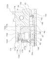
図3に拡大して示すように、シール部材16は、装着溝12eに装着され、貫通孔2fとピニオンギア12との隙間をシールする。シール部材16は、装着溝12eに装着されるリング部16aと、リング部16aと一体形成され、貫通孔2fの内周面に接触する先細りのリップ部16bと、有している。リップ部16bは、前軸受14a側に傾斜している。シール部材16は、貫通孔2fとピニオンギア12との隙間をシールすることによって、リール本体2の空間2dからグリースなどの異物がワンウェイクラッチ組立体51側に浸入するのを防止している。グリースは、駆動ギア11と、ピニオンギア12とのそれぞれのギア歯、及びオシレーティング機構6の後述するトラバースカム軸21の外周面などの係合面、並びに駆動軸11a、スプール軸15及びピニオンギア12などの回転部材の支持部に主に塗布されている。
As shown in an enlarged view in FIG. 3, the
<オシレーティング機構>
オシレーティング機構6は、トラバースカム方式の機構であり、スプール4の中心部に後述するドラグ機構80を介して連結されたスプール軸15を前後方向に往復移動させてスプール4を同方向に往復移動させるための機構である。オシレーティング機構6は、スプール軸15の下方に平行に配置されたトラバースカム軸21と、トラバースカム軸21に沿って前後方向に移動するスライダ22と、トラバースカム軸21の先端に固定された中間ギア23とを有している。スライダ22にはスプール軸15の後端が回転不能に固定されている。中間ギア23は、図示しない減速機構を介してピニオンギア12に噛み合っている。トラバースカム軸21の表面には、交差する螺旋状溝21aが形成されている。
<Oscillating mechanism>
The oscillating mechanism 6 is a traverse cam type mechanism, and the
<ロータ>
ロータ3は、リールボディ2aに回転自在に支持される。ロータ3は、図2に示すように、筒部30と、筒部30の側方に互いに対向して設けられた第1及び第2ロータアーム31,32とを有している。筒部30と両ロータアーム31,32とは、例えばアルミニウム合金製であり一体成形されている。
<Rotor>
The
筒部30の内周部には円形の壁部33が形成されており、壁部33の中心部に筒状の装着部33aが形成されている。装着部33aの中心部にはピニオンギア12の面取り部12bに一体回転可能に連結する長孔形状の取付孔33bが形成されている。この取付孔33bをピニオンギアの前部12a及びスプール軸15が貫通している。この取付孔33bがピニオンギア12の面取り部12bに係合することによって、ロータ3がピニオンギア12に一体回転可能に連結される。装着部33aは、外周部に設けられた、ステンレス合金製の有底筒状の間隙部材36を有している。間隙部材36は、後述する第2シール部材54のシール性能を高めるために設けられる。
A
壁部33の前部にナット13が配置されており、ナット13の内部には、スプール軸15を回転自在に支持する軸受35が配置されている。この軸受35によりピニオンギア12とスプール軸15との間に隙間を形成している。これにより、スプール軸15がたわんでもロータ3の回転に影響を与えにくくなり、ロータ3の回転が軽くなる。ナット13の前面には、ナット13とスプール軸15との隙間をシールする軸シール34が装着されている。軸シール34は、スプール軸15に接触する内周側が先細りのリップ34aを有している。
A nut 13 is disposed in front of the
第1ロータアーム31は、筒部30から外方に凸に湾曲して前方に延びており、筒部30との接続部は筒部30の周方向に広がり湾曲している。第1ロータアーム31の先端の外周側には、第1ベール支持部材40が揺動自在に装着されている。第1ベール支持部材40の先端には、釣り糸をスプール4に案内するためのラインローラ41が装着されている。
The
第2ロータアーム32は、筒部30から外方に凸に湾曲して前方に延びている。第2ロータアーム32は、筒部30から外方に凸に湾曲して前方に延びており、筒部30との接続部は筒部30の周方向に広がり湾曲している。第2ロータアーム32の先端外周側には、第2ベール支持部材42が揺動自在に装着されている。
The
ラインローラ41と第2ベール支持部材42との間には線材を略U状に湾曲させた形状のベール43が固定されている。これらの第1及び第2ベール支持部材40,42、ラインローラ41及びベール43により釣り糸をスプール4に案内するベールアーム44が構成される。ベールアーム44は、図2に示す糸案内姿勢とそれから反転した糸開放姿勢との間で揺動自在である。
Between the
<逆転防止機構>
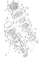
逆転防止機構50は、ロータの筒部30の内部に配置されている。逆転防止機構50は、図3及び図4に示すように、内輪57が遊転するローラ型のワンウェイクラッチ組立体51と、カバー部材52と、第1シール部材53と、第2シール部材54と、切換機構55と、を有している。
<Reverse rotation prevention mechanism>
The reverse
ワンウェイクラッチ組立体51は、取付部2eに取付可能な円形のケース部材56と、ケース部材56に収納される内輪57、外輪58、複数の転動体59、複数のばね部材60(図4参照)及びばね保持部材61と、を有している。ワンウェイクラッチ組立体51は、切換機構55によって、作動状態(逆転禁止状態)と非作動状態(逆転許可状態)とに切り換え可能である。ワンウェイクラッチ組立体51は、ピニオンギア12のギア歯12dよりも前方に配置されている。
The one-way
ケース部材56は、リールボディ2aの取付部2eに固定されている。ケース部材56には、上述した各部が収納される概ね円形の収納空間56aが形成される。収納空間56aの内周面には、外輪58が回転不能に係合する複数(例えば、6個)の凹部56bが周方向に間隔を隔てて形成される。また、ケース部材56には、スプール軸方向に貫通して形成された複数(例えば3つ)のねじ挿通孔56c及び複数(例えば3つ)の第2雌ねじ部56dが周方向に間隔を隔てて交互に配置される。ケース部材56の外周面は、ワンウェイクラッチ組立体51の外周部51aを規定する。
The
内輪57は、ピニオンギア12に回転自在に装着され転動体59に接触する内輪本体62と、内輪本体62をピニオンギア12に回転不能に連結するための連結部材63とを有している。内輪本体62は、大径部62aと小径部62bとを有する段付き筒状部材である。大径部62aには、連結部材63を回転不能に係止するための係止凹部62cが形成されている。係止凹部62cは、正面から見て略矩形の空間である。大径部62aの外周面は転動体59が転動する精密加工された円形の転動面62dである。小径部62bの中心部には、円形の装着孔62eが形成されている。装着孔62eは、ピニオンギア12の面取り部12bが形成されていない外周面に装着され、ピニオンギア12に芯出しされた状態で装着されている。
The
ここでは、転動体59に接触する内輪本体62と連結部材63とに内輪57を分け、内輪本体62をピニオンギア12に回転自在に装着し、内輪本体62とピニオンギア12とに回転不能に係止された連結部材63でピニオンギア12と内輪本体62とを連結しているので、内輪本体62に簡単に高精度な円形の孔を形成することができる。このため、転動体59に接触する内輪本体62をピニオンギア12に高精度に装着することができ、ワンウェイクラッチ組立体51の内輪57とピニオンギア12とのがたつきを抑えることができる。
Here, the
外輪58は、外周部に複数の突出部58aを有しており、これらの突出部58aはケース部材56に設けられた凹部56bに係合している。これにより、外輪58は、ケース部材56に回転不能に設けられる。ここで、突出部58aの先端とケース部材56の凹部56bとの間には径方向の隙間が比較的広く確保され、一方、回転方向へは隙間が狭くなっている。このため、外輪58は、内輪57及び転動体59によって自動調芯されるようになっている。また、外輪58の内周面には転動体59に対してくさび効果を発揮するための湾曲したカム面58bが形成されている。外輪58の軸方向の幅は、転動体59の軸方向の長さよりも短い。
The
複数(例えば5個)の転動体59は、円筒コロ形状である。転動体59は、ばね保持部材61によって保持される。複数(例えば5個)のばね部材60は、転動体59を逆転許容方向に付勢して転動体59を等間隔に配置し、ロータ3が糸繰り出し方向に付勢された状態から糸巻取方向に回転したときの逆転許容動作への応答を速くするために設けられている。
The plurality of (for example, five) rolling
ばね保持部材61は、ケース部材56に回動自在に装着される。ばね保持部材61は、複数のばね部材60を周方向に間隔を隔てて保持するものである。ばね部材60は、複数の転動体59を周方向に間隔を隔てて保持する。また、ばね保持部材61は、逆転許可位置と、逆転許可位置とスプール軸回りの異なる位置に設けられる逆転禁止位置と、に切換機構55によって回動させられる。ばね保持部材61は、周方向に間隔を隔てて配置され前方に突出する複数(例えば5つ)の保持突起61aを有する。ばね部材60は、保持突起61aに形成された保持穴61bに保持される。転動体59は、ばね部材60と保持突起61aとの間に保持される。
The
カバー部材52は、第1カバー部64と、第2カバー部65と、を有している。第1カバー部64は、ワンウェイクラッチ組立体51の前面を覆いかつピニオンギア12が貫通可能なリング状の底部64a、及び底部64aの外周部に一体形成され、ワンウェイクラッチ組立体51の外周部51aと取付部2eの外周部とを覆う筒状部64b、を有する、例えば金属又は合成樹脂等の剛体製の部材である。底部64aは、外輪58の前面に配置され転動体59を抜け止めする。底部64aには、ケース部材56のねじ挿通孔56c及び第2雌ねじ部56dと同じ周方向位置に設けられる複数(例えば6つ)の第1ねじ挿通孔64cが形成される。また、底部64aには、第2カバー部65との間に第2シール部材54を装着するため及び第2カバー部65を第1カバー部64と同芯に配置するための環状の突起部64dが形成されている。筒状部64bの後端部の内周面には、第1シール部材53が配置される配置凹部64e(図3参照)が形成されている。配置凹部64eは、カバー部材52をワンウェイクラッチ組立体51に固定したときに、取付部2eに形成された環状溝2gに対向して配置される。この配置凹部64eと環状溝2gの間に第1シール部材53が配置される。
The
第2カバー部65は、段付きリング状の部材である。第2カバー部65は、第1カバー部64の底部64aの前面に設けられる。第2カバー部65は、内周部において第1カバー部64との間で第2シール部材54の外周部を挟持する。第2カバー部65の外周側には、第1ねじ挿通孔に対向可能な複数(例えば6つ)の第2ねじ挿通孔65a(図4参照)が周方向に間隔を隔てて形成されている。第2カバー部65の後面65b(図3参照)には、突起部64dに嵌合する嵌合部65cが形成されている。突起部64dに嵌合部65cが嵌合することによって第2カバー部65が第1カバー部64に芯出しされる。このように、カバー部材62を第1カバー部64と第2カバー部65とによって構成し、内周部に第2シール部材を挟持するように構成したので、第2シール部材54を装着しやすくなる。
The
第1シール部材53は、カバー部材52の筒状部64b内周面と取付部2eの外周面との隙間をシールするために設けられる。第1シール部材53は、例えば、NBR(ニトリルブタジエンゴム)製又はシリコーンゴム製等の合成ゴム製のOリングである。第1シール部材53は、環状溝2gに装着され、外周部がカバー部材52の配置凹部64eに接触する。
The
第2シール部材54は、例えば、NBR(ニトリルブタジエンゴム)製又はシリコーンゴム製等の合成ゴム製のリング状の部材である。第2シール部材54は、カバー部材52の底部の内周部に装着されるリング部54aと、リング部54aと一体形成され装着部33aの間隙部材36の外周面に接触する先細りのリップ部54bと、を有する。リップ部54bは、リング部54aから前方に向かって傾斜している。
The
切換機構55は、ワンウェイクラッチ組立体51を作動状態と非作動状態とに切り替えるために設けられる。切換機構55は、切換レバー66と、切換板67と、を有している。切換レバー66は、図1に示すようにリールボディ2aの下部にスプール軸15と平行な軸回りに逆転許可位置と逆転禁止位置とに揺動可能に設けられる。切換板67は、図3及び図4に示すように、ケース部材56に回動自在に装着される。ばね保持部材61に一体回動可能に係合する係合孔67aと、切換レバー66に係合する係合部67bは、切換レバー66の揺動に連動して切換板67を回動させるために設けられる。切換板67は、切換レバー66の逆転禁止位置と逆転許可位置との揺動に連動して逆転禁止位置と逆転禁止位置とにスプール軸回りに回動する。この回動がばね保持部材61に伝達され、ワンウェイクラッチ組立体51が作動状態と非作動状態とに切り換えられる。
The
また、逆転防止機構50は、外輪58及びカバー部材62を取付部2eの前面に固定するための第1固定部材としての複数本(例えば3本)の第1ねじ部材70と、カバー部材52を外輪58に固定する第2固定部材としての複数本(例えば3本)の第2ねじ部材72と、をさらに有する。第1ねじ部材70は、第2ねじ部材72よりも長さが長い。第1ねじ部材70は、第2カバー部65の第2ねじ挿通孔65a、第1カバー部64の第1ねじ挿通孔64c、及びケース部材56のねじ挿通孔56cを貫通して取付部2eの第1雌ねじ部2hにねじ込まれる。第2ねじ部材72は、第2カバー部65の第2ねじ挿通孔65a及び第1カバー部64の第1ねじ挿通孔64cを貫通してケース部材56の第2雌ねじ部56dにねじ込まれる。第2ねじ部材72は、カバー部材52と内輪57を除くワンウェイクラッチ組立体51と、をユニット化するために用いられる。第1ねじ部材71は、ユニット化されたワンウェイクラッチ組立体51及びカバー部材52を取付部2eに取り付けられるために設けられる。第1ねじ部材70及び第2ねじ部材72は、例えば、丸頭のボルト部材である。
Further, the reverse
このような構成された逆転防止機構50をリール本体2に組み込む際には、予め、ばね部材60をばね保持部材61の保持穴61bに装着し、さらに転動体59をばね保持部材61に保持させる。また、取付部2eの環状溝2gに第1シール部材53を装着しておく。
When incorporating the reverse
この状態で、切換板67、ばね保持部材61、外輪58をケース部材56の収納空間56aに収納する。次に、第1カバー部64の突起部64dの内周面に第2シール部材54を装着し、第2カバー部65を第1カバー部64に装着する。このとき、第1ねじ挿通孔64cと第2ねじ挿通孔65aとの周方向位置に合わせておく。なお、第1カバー部64と第2カバー部65の周方向位置が合うように、第1カバー部64と第2カバー部65とに周方向位置の位置決め手段を例えば凹凸嵌合等の適宜の位置決め構造によって設けてもよい。
In this state, the switching
これらの作業が終わると、第1カバー部64に第2カバー部65が装着されたカバー部材52を、ケース部材56の外周面に嵌合させ、第2ねじ部材72をケース部材56にねじ込むことによって、内輪57を除くワンウェイクラッチ組立体51とカバー部材52とをユニット化する。ユニット化が終わると、第1ねじ部材70をユニット化されたカバー部材52及びワンウェイクラッチ組立体51を貫通させて取付部2eにねじ込み、カバー部材52及びワンウェイクラッチ組立体51をリール本体2に固定する。
When these operations are completed, the
なお、内輪57は、ピニオンギア12がリール本体2に装着された後にピニオンギア12の面取り部12bに装着される。
The
<スプール>
スプール4は、リールボディ2aに前後往復移動可能に装着され、ロータ3によって外周に釣り糸が巻き付けられる。スプール4は、図2に示すように、ロータ3の第1ロータアーム31と第2ロータアーム32との間に配置されている。スプール4は、2つの軸受81,82によりスプール軸15に回転自在に装着される。スプール4は、糸巻胴部4aと、糸巻胴部と一体形成された大径のスカート部4bと、糸巻胴部の前部に設けられた大径のフランジ部4cと、を有している。糸巻胴部4aの内部にはドラグ機構80が配置されている。スプール4は、スプール軸15とドラグ機構80を介して摩擦係合している。スプール4は、スプール軸15とドラグ機構80を介して摩擦係合している。これにより、スプール4はドラグ機構80が作動しない状態では、スプール軸15に対して回転しない。
<Spool>
The
このように構成されたスピニングリール100では、スピニングリール100を洗浄するとき等に、ロータ3の筒部30の後端部から筒部30の内部に液体が浸入することがある。このとき、浸入した液体は、逆転防止機構50の内部に浸入しようとする。しかし、ワンウェイクラッチ組立体51にカバー部材52が設けられ、カバー部材52に第1シール部材53と第2シール部材54とが設けられているため、カバー部材52の底部及び筒状部からの液体の浸入が阻止される。このため、ワンウェイクラッチ組立体51とリール本体2とを間からの液体の浸入をさらに確実に防止できるようにすることになる。
T2840と同じです。
In the
Same as T2840.
<他の実施形態>
以上、本発明の一実施形態について説明したが、本発明は上記実施形態に限定されるものではなく、発明の要旨を逸脱しない範囲で種々の変更が可能である。特に、本明細書に書かれた複数の実施形態及び変形例は必要に応じて任意に組合せ可能である。
<Other embodiments>
As mentioned above, although one Embodiment of this invention was described, this invention is not limited to the said embodiment, A various change is possible in the range which does not deviate from the summary of invention. In particular, a plurality of embodiments and modifications described in this specification can be arbitrarily combined as necessary.
なお、以降の説明では、前記実施形態と同様な構成の部材については、前記実施形態と異なる部材を3桁の符号で表して説明し、前記実施形態と実質的に同じ構成の部材を前記実施形態と同じ符号で表し、その説明を省略することがある。 In the following description, for members having the same configuration as in the above embodiment, members different from those in the above embodiment will be described using three-digit symbols, and members having substantially the same configuration as in the above embodiment will be described. It may be represented by the same reference numeral as the form, and the description thereof may be omitted.
(a)前記実施形態では、逆転防止機構50のワンウェイクラッチ組立体51が取付部2eの前面に取り付けられているが、本発明はこれに限定されない。図5及び図6に示すように、ワンウェイクラッチ組立体151が取付部102eの内部に設けられるスピニングリールにも本発明を適用できる。
(A) Although the one-way
図5及び図6において、リールボディ102aの円形の取付部102eは、先端が開口しワンウェイクラッチ組立体151を収納可能な円形の収納空間102gを有している。また、リールボディ102aの貫通孔2fに前軸受14aが装着されている。前軸受14aは、収納空間102gの底部に固定された環状の規制板176によって前方への移動が規制される。規制板176は、底部にねじ込まれる複数本(例えば4本の)皿ネジ179によって収納空間102gの底部に固定される。
5 and 6, the
収納空間102gには、抜け止め部材174が装着される環状の装着溝102hと、後述する外輪58の突出部58aが係合する複数(例えば6つ)の凹部102iと、が形成されている。複数の凹部102i、周方向に間隔を隔てて配置されている。
The
逆転防止機構150は、内輪57が遊転するローラ型のワンウェイクラッチ組立体151と、第3シール部材169と、抜け止め部材174と、切換機構55と、を有している。
The reverse
ワンウェイクラッチ組立体151は、取付部102eの収納空間102gに収納される内輪57、外輪58、複数の転動体59、複数のばね部材60(図6参照)及びばね保持部材61と、を有している。したがって、ケース部材56が設けられていない点が前記実施形態と異なる。ワンウェイクラッチ組立体151は、切換機構55によって、作動状態(逆転禁止状態)と非作動状態(逆転許可状態)とに切り換え可能である。ワンウェイクラッチ組立体151は、ピニオンギア12のギア歯12dよりも前方に配置されている。
The one-way
内輪57は、前記実施形態と同様な構成であり、ピニオンギア12に回転自在に装着され転動体59に接触する内輪本体62と、内輪本体62をピニオンギア12に回転不能に連結するための連結部材63とを有している。
The
外輪58は、外周部に複数の突出部58aを有しており、これらの突出部58aは収納空間102gに設けられた凹部102iに係合している。これにより、外輪58は、収納空間102gに回転不能に設けられる。ここで、突出部58aの先端と収納空間102gの凹部102iとの間には径方向の隙間が比較的広く確保され、一方、回転方向へは隙間が狭くなっている。このため、前記実施形態と同様に外輪58は、内輪57及び転動体59によって自動調芯されるようになっている。また、外輪58の内周面には転動体59に対してくさび効果を発揮するための湾曲したカム面58bが形成されている。外輪58の軸方向の幅は、転動体59の軸方向の長さよりも短い。
The
複数の転動体59は、前記実施形態と同様な構成であり、円筒コロ形状である。転動体59は、ばね保持部材61によって保持される。
The plurality of rolling
ばね部材60、ばね保持部材61は、前記実施形態と同様な構成である。ばね保持部材61は、保持突起61aと保持穴61bとを有する。ばね保持部材61は、収納空間102gに回動自在に装着される。ばね保持部材61は、複数のばね部材60を周方向に間隔を隔てて保持する。
The
第3シール部材169は、外輪58の前面で収納空間102gをシールする。第3シール部材169は、NBR(ニトリルブタジエンゴム)製またはシリコーンゴム製等の合成ゴム製のシール本体177と、シール本体177を補強する金属製のバックアップリング178と、を有する。シール本体177は、外周側に収納空間102gの内周面及び外輪58の前面に接触する接触部177aを有し、内周側に前方に向けて傾斜する先細りのリップ部177bを有する。リップ部177bは、ロータ3の装着部33aの間隙部材36に接触する。この第3シール部材169は、比較大きな面積を有するため、バックアップリング178によって補強されている。すなわち、第3シール部材169は、収納空間102gの開口を塞ぐ蓋部材としての機能も備えている。
The
抜け止め部材174は、金属製のばね線材を変形四角形状に折り曲げて形成されている。抜け止め部材174は、図6に示すように、装着溝102hに装着可能な複数の径方向外方に向けて凸に湾曲する円弧部174aと、複数の円弧部174aを連結する径方向内方に向けて凸に湾曲して連結部174bと、を有し、円弧部174aを装着溝102hに装着し、連結部174bを第3シール部材169の前面に接触させることによって第3シール部材169を抜け止めする。第3シール部材169の後面と転動体59との間には隙間があくため、その隙間を埋めて転動体59のガタツキを抑えるための合成樹脂製のワッシャ180が配置される。
The retaining
ワンウェイクラッチ組立体151を作動状態と非作動状態とに切り替えるために切換機構55は、前記実施形態と同様な構成である。切換機構55は、切換レバー66と、切換板67と、を有している。
In order to switch the one-way
このような構成のスピニングリールでは、逆転防止機構150の構成が簡素になる。
In the spinning reel having such a configuration, the configuration of the reverse
(b)前記実施形態では、フロントドラグ形のスピニングリールを例に本発明を説明したが、リアドラグ形のスピニングリールにも本発明を適用できる。 (B) In the above embodiment, the present invention has been described by taking a front drag type spinning reel as an example, but the present invention can also be applied to a rear drag type spinning reel.
(c)前記実施形態では、第1シール部材にOリングを用いたが第1シール部材にリップ付きのシール部材等のOリング以外の環状のシール部材を用いてもよい。また、第2シール部材にOリング等の他の形態のシール部材を用いてもよい。 (C) In the above embodiment, the O-ring is used as the first seal member, but an annular seal member other than the O-ring such as a seal member with a lip may be used as the first seal member. Moreover, you may use the sealing member of other forms, such as an O-ring, for a 2nd sealing member.
(d)前記実施形態では、カバー部材52を第1カバー部64と第2カバー部65とによって構成したが、本発明はこれに限定されない。カバー部材は、有底筒状の一つの部材で構成してもよい。
(D) In the said embodiment, although the
(e)前記実施形態では、ロータ3の装着部33aは間隙部材36を有し、第2シール部材54を間隙部材36に接触させているが、本発明はこれに限定されない。例えば、装着部33aに間隙部材を設けなくてもよい。この場合、第2シール部材を装着部33aに直接接触させてもよい。
(E) In the above embodiment, the mounting
<特徴>
上記実施形態は、下記のように表現可能である。
<Features>
The above embodiment can be expressed as follows.
(A)スピニングリール100は、釣り糸を前方に繰り出すリールである。スピニングリール100は、ハンドル1と、リール本体2と、ロータ3と、スプール4と、ロータ駆動機構5と、逆転防止機構50(又は150)と、を備えている。リール本体2は、釣り竿を装着可能な竿装着部2bと、前部に設けられ中心に前後方向に配置された貫通孔2fを有する円形の取付部2e(又は102e)と、を有し、ハンドル1を回転自在に支持する。ロータ3は、筒状の装着部33aを有し、リール本体2に回転自在に装着される。スプール4は、リール本体2に前後往復移動可能に装着され、ロータ3によって釣り糸が巻き付けられる。ロータ駆動機構5は、駆動ギア11と筒状のピニオンギア12と、を有する。駆動ギア11は、フェースギア歯を有し、ハンドル1の回転に連動して回転する。ピニオンギア12は、ロータ3の装着部33aが前部に一体回転可能に連結され、貫通孔2fを貫通して前後方向に配置され、駆動ギア11にかみ合う。逆転防止機構50(又は150)は、リールボディ2a(又は102a)の取付部2e(又は102e)に着脱可能に取り付けられる内輪遊転型のワンウェイクラッチ組立体51(又は151)を有し、ロータ3の糸繰り出し方向の回転を禁止する。ロータ駆動機構5は、ワンウェイクラッチ組立体51(又は151)よりも後方でピニオンギア12と貫通孔2fの隙間をシールするシール部材16を有する。
(A) The
このスピニングリール100では、ロータ駆動機構5において、ワンウェイクラッチ組立体51(又は151)よりも後方でピニオンギア12とピニオンギア12が配置される貫通孔2fとの隙間がシール部材16によってシールされる。このため、リールボディ2a(又は102a)の内部から逆転防止機構50(又は150)への異物の侵入を抑えることができる。また、逆転防止機構50(又は150)からリールボディ2a(又は102a)の内部への異物の侵入も抑えることができる。
In the
(B)シール部材16は、ピニオンギア12の外周部に形成された環状の装着溝12eに装着され、貫通孔2fの内周面に接触して配置されてもよい。この場合には、ピニオンギア12とともにシール部材16が回転するので、異物が遠心力によって飛散し、異物がさらに逆転防止機構50(150)に侵入しにくい。
(B) The
(C)シール部材16は、装着溝12eに装着されるリング部16aと、リング部16aと一体形成され、貫通孔2eの内周面に接触する先細りのリップ部16bと、有してもよい。この場合には、シール部材16の貫通孔2eの内周面に接触する部分が先細りのリップ部16bであるので、シール部材16が回転しても摺動抵抗が小さくなり、ピニオンギア12の回転性能の低下を抑えることができる。
(C) The
(D)ピニオンギア12は、ワンウェイクラッチ組立体51(又は151)よりも後方に配置され、フェースギア歯にかみ合うギア歯12dを有し、ギア歯12dの両側で前後に間隔を隔てて配置される前軸受14aと後軸受14bを介してリールボディ2a(102a)に回転自在に支持されてもよい。シール部材16は、前軸受14aよりも後方に配置される。この場合には、前軸受14aへの異物の侵入を抑えることができる。
(D) The
(E)リップ部16bは、前軸受14a側に傾斜していてもよい。この場合には、シール部材16をピニオンギア12に装着した状態でピニオンギア12をリールボディ2a(又は102a)の前部から装着してもリップ部16bが倒れにくくなる。このため、リップ部16bを変形させることなくピニオンギア12をリールボディ2a(又は102a)に装着できる。
(E) The
(F)逆転防止機構50は、ワンウェイクラッチ組立体51の前面を覆いかつピニオンギア12が貫通可能なリング状の底部64a、及びワンウェイクラッチ組立体51の外周部51aと取付部2eの外周部とを覆う筒状部64b、を有する防水用のカバー部材52をさらに有してもよい。この場合には、ワンウェイクラッチ組立体51を取付部2eの前面に取り付けても取付部2eとワンウェイクラッチ組立体51との境界部分からワンウェイクラッチ組立体51の内部に異物が侵入しにくくなる。
(F) The reverse
(G)ワンウェイクラッチ組立体51は、取付部2eに取付可能でありワンウェイクラッチクラッチ組立体51の外周部51aを有する円形のケース部材56と、ピニオンギア12に一体回転可能に連結された内輪57と、ケース部材56に回転不能に設けられる外輪58と、内輪57と外輪58との間に配置された複数の転動体59と、を有してもよい。この場合には、ケース部材56の内部に内輪57、外輪58及び転動体59を配置できるので、ワンウェイクラッチ組立体51をユニット化できる。このため、予めワンウェイクラッチ組立体51を組み立てておくことができ、ワンウェイクラッチ組立体51のリールボディ2aへの組み込みが容易である。
(G) The one-way
(H)逆転防止機構50は、取付部2eと筒状部64bの隙間をシールする第1シール部材53と、ロータ3の装着部33aとカバー部材52の底部64aの隙間をシールする第2シール部材54と、をさらに有してもよい。この場合には、カバー部材52の筒状部64bと取付部2eとの隙間及びカバー部材52とロータ3の装着部33aとの隙間をシールできるので、ワンウェイクラッチ組立体51の内部への異物の侵入をさらに抑えることができる。
(H) The reverse
(I)第1シール部材53は、取付部2eの外周部に形成された環状溝2gに装着され、筒状部64bの内周面に接触して配置される。この場合には、第1シール部材53が環状溝2gに装着されるので、カバー部材52を取付部2eに装着しやすい。
(I) The
(J)逆転防止機構50は、カバー部材52及びケース部材56を貫通して取付部2eにねじ込まれ、周方向に間隔を隔てて配置された複数の第1ねじ部材70をさらに有してもよい。この場合には、第1ねじ部材70を取付部2eにねじ込むことによって、ワンウェイクラッチ組立体51及びカバー部材52を一括して取付部2eに固定できる。
(J) The reverse
(K)逆転防止機構50は、カバー部材52を貫通してケース部材56にねじ込まれる第2ねじ材72をさらに有してもよい。この場合には、第2ねじ部材72をケース部材56にねじ込むことにより、カバー部材52を含むワンウェイクラッチ組立体51をユニット化できる。
(K) The reverse
(L)取付部102eは、先端が開口しワンウェイクラッチ組立体151を収納可能な円形の収納空間102gを有してもよい。ワンウェイクラッチ組立体151は、ピニオンギア12に一体回転可能に連結された内輪57と、収納空間102gに回転不能に設けられる外輪58と、内輪57と外輪58との間に配置された複数の転動体59と、を有する。この場合には、ワンウェイクラッチ組立体151がリールボディ102aに設けられる収納空間102gに収納されるので、逆転防止機構150の構成が簡素化できる。
(L) The
(M)逆転防止機構150は、第3シール部材169と抜け止め部材174と、さらに有してもよい。第3シール部材169は、外輪58の前面で収納空間102gをシールする。抜け止め部材174は、第3シール部材169を収納空間102gに対して抜け止めする。この場合には、第3シール部材169によって収納空間102gに異物が侵入しにくくなる。また、抜け止め部材174によって第3シール部材169が収納空間102gから抜けなくなる。
(M) The reverse
1 ハンドル
2 リール本体
2b 竿装着部
2e,102e 取付部
2g,102g 環状溝
3 ロータ
4 スプール
5 ロータ駆動機構
11 駆動ギア
12 ピニオンギア
12e 装着溝
16 シール部材
33a 装着部
50 逆転防止機構
51 ワンウェイクラッチ組立体
52 カバー部材
53 第1シール部材
54 第2シール部材
56 ケース部材
57 内輪
58 外輪
59 転動体
64,164 第1カバー部
64a,164a 底部
64b,164b 筒状部
65,165 第2カバー部
70 第1ねじ部材(第1固定部材)
72 第2ねじ部材(第2固定部材)
DESCRIPTION OF
72 Second screw member (second fixing member)
Claims (13)
ハンドルと、
釣り竿を装着可能な竿装着部と、前部に設けられ中心に前後方向に配置された貫通孔を有する円形の取付部と、を有し、前記ハンドルを回転自在に支持するリール本体と、
筒状の装着部を有し、前記リール本体に回転自在に装着されるロータと、
前記リール本体に前後往復移動可能に装着され、前記ロータによって前記釣り糸が巻き付けられるスプールと、
フェースギア歯を有し、前記ハンドルの回転に連動して回転する駆動ギア、及び前記ロータの前記装着部が前部に一体回転可能に連結され、前記貫通孔を貫通して前後方向に配置され、前記駆動ギアにかみ合う筒状のピニオンギア、を有するロータ駆動機構と、
前記リール本体の前記取付部に着脱可能に取り付けられる内輪遊転型のワンウェイクラッチ組立体を有し、前記ロータの糸繰り出し方向の回転を禁止する逆転防止機構と、を備え、
前記ロータ駆動機構は、前記ワンウェイクラッチ組立体よりも後方で、前記ピニオンギアと、前記貫通孔と、の隙間をシールするシール部材を有する、スピニングリール。 A spinning reel that feeds fishing line forward,
A handle,
A reel body that has a rod mounting portion on which a fishing rod can be mounted, and a circular mounting portion that has a through hole that is provided in the front portion and is disposed in the front-rear direction at the center, and rotatably supports the handle;
A rotor having a cylindrical mounting portion and rotatably mounted on the reel body;
A spool that is mounted on the reel body so as to be capable of reciprocating back and forth, and on which the fishing line is wound by the rotor;
A drive gear having face gear teeth and rotating in conjunction with rotation of the handle and the mounting portion of the rotor are connected to the front portion so as to be integrally rotatable, and are disposed in the front-rear direction through the through hole. A rotor drive mechanism having a cylindrical pinion gear meshing with the drive gear;
An inner ring idle type one-way clutch assembly that is detachably attached to the attachment portion of the reel body, and includes a reverse rotation prevention mechanism that prohibits rotation of the rotor in a yarn unwinding direction,
The spinning reel, wherein the rotor driving mechanism includes a seal member that seals a gap between the pinion gear and the through hole at a rear side of the one-way clutch assembly.
前記シール部材は、前記前軸受よりも後方に配置される、請求項3項に記載のスピニングリール。 The pinion gear is disposed rearward of the one-way clutch assembly, has gear teeth that mesh with the face gear teeth, and includes a front bearing and a rear bearing that are disposed on both sides of the gear teeth at an interval in the front-rear direction. Via the reel body, and is supported rotatably.
The spinning reel according to claim 3, wherein the seal member is disposed rearward of the front bearing.
前記ワンウェイクラッチ組立体は、前記ピニオンギアに一体回転可能に連結された内輪と、前記収納空間に回転不能に設けられる外輪と、前記内輪と前記外輪との間に配置された複数の転動体と、を有する、請求項1から5のいずれか1項に記載のスピニングリール。 The mounting portion has a circular storage space that is open at the tip and can store the one-way clutch assembly.
The one-way clutch assembly includes an inner ring coupled to the pinion gear so as to be integrally rotatable, an outer ring provided in a non-rotatable manner in the storage space, and a plurality of rolling elements disposed between the inner ring and the outer ring. The spinning reel according to claim 1, comprising:
前記外輪の前面で前記収納空間をシールする第3シール部材と、
前記第3シール部材を前記筒状部に対して抜け止めする抜け止め部材と、をさらに有する、請求項12に記載のスピニングリール。 The reverse rotation prevention mechanism is
A third seal member that seals the storage space at the front surface of the outer ring;
The spinning reel according to claim 12, further comprising a retaining member that retains the third seal member with respect to the cylindrical portion.
Priority Applications (7)
| Application Number | Priority Date | Filing Date | Title |
|---|---|---|---|
| JP2013107173A JP2014226071A (en) | 2013-05-21 | 2013-05-21 | Spinning reel |
| US14/247,744 US9497948B2 (en) | 2013-05-21 | 2014-04-08 | Spinning reel |
| EP14165030.9A EP2805614B1 (en) | 2013-05-21 | 2014-04-16 | Spinning reel |
| MYPI2014700978A MY176660A (en) | 2013-05-21 | 2014-04-22 | Spinning reel |
| TW103114664A TWI622346B (en) | 2013-05-21 | 2014-04-23 | Spinning reel |
| KR20140054774A KR20140136870A (en) | 2013-05-21 | 2014-05-08 | Spinning reel |
| CN201410215276.1A CN104170804A (en) | 2013-05-21 | 2014-05-21 | Spinning wire-winding reel |
Applications Claiming Priority (1)
| Application Number | Priority Date | Filing Date | Title |
|---|---|---|---|
| JP2013107173A JP2014226071A (en) | 2013-05-21 | 2013-05-21 | Spinning reel |
Publications (2)
| Publication Number | Publication Date |
|---|---|
| JP2014226071A true JP2014226071A (en) | 2014-12-08 |
| JP2014226071A5 JP2014226071A5 (en) | 2016-07-07 |
Family
ID=50479147
Family Applications (1)
| Application Number | Title | Priority Date | Filing Date |
|---|---|---|---|
| JP2013107173A Pending JP2014226071A (en) | 2013-05-21 | 2013-05-21 | Spinning reel |
Country Status (7)
| Country | Link |
|---|---|
| US (1) | US9497948B2 (en) |
| EP (1) | EP2805614B1 (en) |
| JP (1) | JP2014226071A (en) |
| KR (1) | KR20140136870A (en) |
| CN (1) | CN104170804A (en) |
| MY (1) | MY176660A (en) |
| TW (1) | TWI622346B (en) |
Cited By (2)
| Publication number | Priority date | Publication date | Assignee | Title |
|---|---|---|---|---|
| KR20190011661A (en) * | 2017-07-25 | 2019-02-07 | 가부시키가이샤 시마노 | Roller clutch for fishing reel |
| JP2020150802A (en) * | 2019-03-18 | 2020-09-24 | シマノコンポネンツ マレーシア エスディーエヌ.ビーエッチディー. | Fishing reel |
Families Citing this family (7)
| Publication number | Priority date | Publication date | Assignee | Title |
|---|---|---|---|---|
| JP6419020B2 (en) * | 2015-04-28 | 2018-11-07 | グローブライド株式会社 | Fishing spinning reel |
| JP6688603B2 (en) * | 2015-12-14 | 2020-04-28 | 株式会社シマノ | Spinning reel rotor and spinning reel |
| JP6700778B2 (en) * | 2015-12-25 | 2020-05-27 | 株式会社シマノ | Line roller |
| JP7227781B2 (en) * | 2019-02-08 | 2023-02-22 | 株式会社シマノ | Double-bearing reel spool and double-bearing reel |
| US11350617B2 (en) | 2019-06-21 | 2022-06-07 | Trika Inc. | Left handed fishing reel |
| CN112408309B (en) * | 2020-12-14 | 2021-08-20 | 义乌市君胜科技有限公司 | Filling station is with adding oil pipe wind |
| JP2023149353A (en) * | 2022-03-31 | 2023-10-13 | グローブライド株式会社 | spinning reel for fishing |
Citations (6)
| Publication number | Priority date | Publication date | Assignee | Title |
|---|---|---|---|---|
| JP2000279066A (en) * | 1999-03-31 | 2000-10-10 | Daiwa Seiko Inc | Reel for fishing |
| JP2001112383A (en) * | 1999-10-14 | 2001-04-24 | Shimano Inc | Spinning reel |
| JP2003284458A (en) * | 2002-03-29 | 2003-10-07 | Daiwa Seiko Inc | Reel for fishing |
| JP2009063052A (en) * | 2007-09-05 | 2009-03-26 | Shimano Inc | Roller clutch |
| JP2010273581A (en) * | 2009-05-27 | 2010-12-09 | Globeride Inc | Fishing reel |
| JP2010273618A (en) * | 2009-05-29 | 2010-12-09 | Globeride Inc | Spinning reel for fishing |
Family Cites Families (21)
| Publication number | Priority date | Publication date | Assignee | Title |
|---|---|---|---|---|
| JP3839972B2 (en) | 1998-09-17 | 2006-11-01 | 株式会社シマノ | Spinning reel waterproof structure |
| TW440425B (en) * | 1999-07-14 | 2001-06-16 | Shimano Kk | Rotor drive for spinning reel and spinning reel |
| JP3759573B2 (en) * | 2000-04-25 | 2006-03-29 | 株式会社シマノ | Spinning reel bale reversing device |
| JP4187911B2 (en) * | 2000-07-27 | 2008-11-26 | ダイワ精工株式会社 | Fishing reel |
| TW495343B (en) * | 2000-11-13 | 2002-07-21 | Shimano Kk | Spinning reel rotor |
| JP2002267028A (en) * | 2001-03-07 | 2002-09-18 | Shimano Inc | Parts assembly |
| JP4045167B2 (en) * | 2002-05-01 | 2008-02-13 | 株式会社シマノ | Spinning reel handle assembly |
| SG114660A1 (en) * | 2003-04-16 | 2005-09-28 | Shimano Kk | Sound generating mechanism for a fishing reel |
| US7175121B2 (en) * | 2003-10-28 | 2007-02-13 | Shimano Inc. | Spinning reel sounding mechanism |
| SG118339A1 (en) * | 2004-06-09 | 2006-01-27 | Shimano Kk | Spinning-reel sounding mechanism |
| SG127795A1 (en) * | 2005-05-31 | 2006-12-29 | Shimano Kk | Spinning reel |
| JP4804330B2 (en) * | 2006-12-21 | 2011-11-02 | 株式会社シマノ | Spinning reel body |
| SG144041A1 (en) * | 2006-12-21 | 2008-07-29 | Shimano Kk | Reel unit of spinning reel |
| MY162139A (en) * | 2007-09-14 | 2017-05-31 | Shimano Kk | Spining reel |
| JP5746462B2 (en) * | 2009-08-20 | 2015-07-08 | 株式会社シマノ | Spinning reel spool connection structure |
| JP4886066B2 (en) * | 2010-01-19 | 2012-02-29 | グローブライド株式会社 | Fishing spinning reel |
| JP2011193855A (en) * | 2010-03-24 | 2011-10-06 | Shimano Components Malaysia Sdn Bhd | Master gear assembly |
| JP2011231889A (en) | 2010-04-28 | 2011-11-17 | Globeride Inc | Bearing with magnetic fluid seal |
| KR101930538B1 (en) * | 2010-08-27 | 2018-12-18 | 글로브라이드 가부시키가이샤 | Reel for fishing |
| US9091350B2 (en) * | 2012-02-10 | 2015-07-28 | Shimano Inc. | Spinning reel waterproofing member and spinning reel using the same |
| JP6039454B2 (en) * | 2013-02-18 | 2016-12-07 | シマノコンポネンツ マレーシア エスディーエヌ.ビーエッチディー. | Spinning reel thread locker and spinning reel spool using the same |
-
2013
- 2013-05-21 JP JP2013107173A patent/JP2014226071A/en active Pending
-
2014
- 2014-04-08 US US14/247,744 patent/US9497948B2/en active Active
- 2014-04-16 EP EP14165030.9A patent/EP2805614B1/en active Active
- 2014-04-22 MY MYPI2014700978A patent/MY176660A/en unknown
- 2014-04-23 TW TW103114664A patent/TWI622346B/en active
- 2014-05-08 KR KR20140054774A patent/KR20140136870A/en not_active Application Discontinuation
- 2014-05-21 CN CN201410215276.1A patent/CN104170804A/en active Pending
Patent Citations (6)
| Publication number | Priority date | Publication date | Assignee | Title |
|---|---|---|---|---|
| JP2000279066A (en) * | 1999-03-31 | 2000-10-10 | Daiwa Seiko Inc | Reel for fishing |
| JP2001112383A (en) * | 1999-10-14 | 2001-04-24 | Shimano Inc | Spinning reel |
| JP2003284458A (en) * | 2002-03-29 | 2003-10-07 | Daiwa Seiko Inc | Reel for fishing |
| JP2009063052A (en) * | 2007-09-05 | 2009-03-26 | Shimano Inc | Roller clutch |
| JP2010273581A (en) * | 2009-05-27 | 2010-12-09 | Globeride Inc | Fishing reel |
| JP2010273618A (en) * | 2009-05-29 | 2010-12-09 | Globeride Inc | Spinning reel for fishing |
Cited By (6)
| Publication number | Priority date | Publication date | Assignee | Title |
|---|---|---|---|---|
| KR20190011661A (en) * | 2017-07-25 | 2019-02-07 | 가부시키가이샤 시마노 | Roller clutch for fishing reel |
| JP2019024327A (en) * | 2017-07-25 | 2019-02-21 | 株式会社シマノ | Roller clutch of fishing reel |
| KR102566957B1 (en) | 2017-07-25 | 2023-08-16 | 가부시키가이샤 시마노 | Roller clutch for fishing reel |
| JP2020150802A (en) * | 2019-03-18 | 2020-09-24 | シマノコンポネンツ マレーシア エスディーエヌ.ビーエッチディー. | Fishing reel |
| JP7227807B2 (en) | 2019-03-18 | 2023-02-22 | シマノコンポネンツ マレーシア エスディーエヌ.ビーエッチディー. | fishing reel |
| TWI798497B (en) * | 2019-03-18 | 2023-04-11 | 馬來西亞商島野馬來西亞配件廠有限公司 | fishing reel |
Also Published As
| Publication number | Publication date |
|---|---|
| US9497948B2 (en) | 2016-11-22 |
| US20140346266A1 (en) | 2014-11-27 |
| EP2805614A1 (en) | 2014-11-26 |
| CN104170804A (en) | 2014-12-03 |
| EP2805614B1 (en) | 2018-07-25 |
| MY176660A (en) | 2020-08-19 |
| TWI622346B (en) | 2018-05-01 |
| KR20140136870A (en) | 2014-12-01 |
| TW201509298A (en) | 2015-03-16 |
Similar Documents
| Publication | Publication Date | Title |
|---|---|---|
| JP2014226071A (en) | Spinning reel | |
| JP2014226071A5 (en) | ||
| US9091350B2 (en) | Spinning reel waterproofing member and spinning reel using the same | |
| JP4804279B2 (en) | Spinning reel | |
| JP5961407B2 (en) | Spinning reel waterproofing member and spinning reel using the same | |
| JP5961399B2 (en) | Spinning reel waterproofing material | |
| KR101806336B1 (en) | Master gear assembly | |
| KR102002854B1 (en) | Handle assembly for spinning reel | |
| JP2006217848A5 (en) | ||
| JP2006217848A (en) | Handle assembly for spinning reel | |
| JP2011193855A5 (en) | ||
| JP3840009B2 (en) | Spinning reel | |
| JP2010279259A5 (en) | ||
| EP3289870A1 (en) | Rotor drive unit waterproof structure and spinning reel | |
| JP6235238B2 (en) | Spinning reel | |
| JP2014226070A5 (en) | ||
| JP6615057B2 (en) | Fishing reel | |
| JP5254885B2 (en) | Fishing spinning reel | |
| JP6261971B2 (en) | Spinning reel | |
| JP2001025338A (en) | Rotor drive for spinning reel | |
| JP2003079289A (en) | One-way clutch of fishing reel | |
| JP5185177B2 (en) | Spindle reel handle mounting structure | |
| JP6110128B2 (en) | Spinning reel and spinning reel spool | |
| CN104170803B (en) | Spinning-reel | |
| JP2007209217A (en) | Spinning reel for fishing |
Legal Events
| Date | Code | Title | Description |
|---|---|---|---|
| A521 | Request for written amendment filed |
Free format text: JAPANESE INTERMEDIATE CODE: A523 Effective date: 20160518 |
|
| A621 | Written request for application examination |
Free format text: JAPANESE INTERMEDIATE CODE: A621 Effective date: 20160518 |
|
| A977 | Report on retrieval |
Free format text: JAPANESE INTERMEDIATE CODE: A971007 Effective date: 20170224 |
|
| A131 | Notification of reasons for refusal |
Free format text: JAPANESE INTERMEDIATE CODE: A131 Effective date: 20170314 |
|
| A02 | Decision of refusal |
Free format text: JAPANESE INTERMEDIATE CODE: A02 Effective date: 20171107 |