JP6046481B2 - Spinning reel and spinning reel spool - Google Patents
Spinning reel and spinning reel spool Download PDFInfo
- Publication number
- JP6046481B2 JP6046481B2 JP2012277878A JP2012277878A JP6046481B2 JP 6046481 B2 JP6046481 B2 JP 6046481B2 JP 2012277878 A JP2012277878 A JP 2012277878A JP 2012277878 A JP2012277878 A JP 2012277878A JP 6046481 B2 JP6046481 B2 JP 6046481B2
- Authority
- JP
- Japan
- Prior art keywords
- spool
- ring member
- spinning reel
- annular
- main body
- Prior art date
- Legal status (The legal status is an assumption and is not a legal conclusion. Google has not performed a legal analysis and makes no representation as to the accuracy of the status listed.)
- Active
Links
- 238000009987 spinning Methods 0.000 title claims description 50
- 230000002093 peripheral effect Effects 0.000 claims description 63
- 238000003825 pressing Methods 0.000 claims description 15
- 238000002788 crimping Methods 0.000 description 5
- 238000005260 corrosion Methods 0.000 description 4
- 230000007797 corrosion Effects 0.000 description 4
- 239000011347 resin Substances 0.000 description 4
- 229920005989 resin Polymers 0.000 description 4
- 239000013535 sea water Substances 0.000 description 4
- 125000004122 cyclic group Chemical group 0.000 description 2
- 238000010586 diagram Methods 0.000 description 2
- 230000000694 effects Effects 0.000 description 2
- 238000000034 method Methods 0.000 description 2
- 230000002265 prevention Effects 0.000 description 2
- 239000000463 material Substances 0.000 description 1
- 238000012986 modification Methods 0.000 description 1
- 230000004048 modification Effects 0.000 description 1
- 238000012856 packing Methods 0.000 description 1
- 230000001105 regulatory effect Effects 0.000 description 1
- 238000004804 winding Methods 0.000 description 1
Images


Classifications
-
- A—HUMAN NECESSITIES
- A01—AGRICULTURE; FORESTRY; ANIMAL HUSBANDRY; HUNTING; TRAPPING; FISHING
- A01K—ANIMAL HUSBANDRY; AVICULTURE; APICULTURE; PISCICULTURE; FISHING; REARING OR BREEDING ANIMALS, NOT OTHERWISE PROVIDED FOR; NEW BREEDS OF ANIMALS
- A01K89/00—Reels
- A01K89/02—Brake devices for reels
- A01K89/027—Brake devices for reels with pick-up, i.e. for reels with the guiding member rotating and the spool not rotating during normal retrieval of the line
-
- A—HUMAN NECESSITIES
- A01—AGRICULTURE; FORESTRY; ANIMAL HUSBANDRY; HUNTING; TRAPPING; FISHING
- A01K—ANIMAL HUSBANDRY; AVICULTURE; APICULTURE; PISCICULTURE; FISHING; REARING OR BREEDING ANIMALS, NOT OTHERWISE PROVIDED FOR; NEW BREEDS OF ANIMALS
- A01K89/00—Reels
- A01K89/01—Reels with pick-up, i.e. with the guiding member rotating and the spool not rotating during normal retrieval of the line
- A01K89/0111—Spool details
-
- A—HUMAN NECESSITIES
- A01—AGRICULTURE; FORESTRY; ANIMAL HUSBANDRY; HUNTING; TRAPPING; FISHING
- A01K—ANIMAL HUSBANDRY; AVICULTURE; APICULTURE; PISCICULTURE; FISHING; REARING OR BREEDING ANIMALS, NOT OTHERWISE PROVIDED FOR; NEW BREEDS OF ANIMALS
- A01K89/00—Reels
- A01K89/01—Reels with pick-up, i.e. with the guiding member rotating and the spool not rotating during normal retrieval of the line
Landscapes
- Life Sciences & Earth Sciences (AREA)
- Environmental Sciences (AREA)
- Animal Husbandry (AREA)
- Biodiversity & Conservation Biology (AREA)
Description
本発明は、釣り糸を前方に繰り出すスピニングリール、及びスピニングリールのスプールに関する。 The present invention relates to a spinning reel that feeds fishing line forward, and a spool of the spinning reel.
従来のスピニングリールは、スプール本体と、当接部材と、リング部材とを、備えている。このタイプのスピニングリールでは、リング部材が、当接部材とスプール本体とによって挟持されている。具体的には、リング部材をスプール本体の前側にセットした状態において、当接部材をスプール本体に装着することによって、リング部材が当接部材とスプール本体とによって挟持されている。 A conventional spinning reel includes a spool body, a contact member, and a ring member. In this type of spinning reel, the ring member is sandwiched between the contact member and the spool body. Specifically, in a state where the ring member is set on the front side of the spool body, the ring member is sandwiched between the contact member and the spool body by mounting the contact member on the spool body.
従来の構成では、リング部材が、当接部材とスプール本体とによって挟持されている。この構成では、スプール本体、当接部材(スプールカラー)、及びリング部材(スプールリング)によって囲まれた空間(密閉空間)が、スプールの前部の外周部に形成される。このため、一旦、この密閉空間に、海水等のような異物が、侵入してしまうと、この異物の影響でスプール本体が腐食してしまうおそれがある。すなわち、スプール本体の耐久性が低下してしまうおそれがある。 In the conventional configuration, the ring member is sandwiched between the contact member and the spool body. In this configuration, a space (sealed space) surrounded by the spool body, the contact member (spool collar), and the ring member (spool ring) is formed in the outer peripheral portion of the front portion of the spool. For this reason, once foreign matter such as seawater enters the sealed space, the spool body may corrode due to the influence of the foreign matter. That is, the durability of the spool body may be reduced.
また、当接部材はリング部材を押圧した状態でリング部材に当接しているので、スプールの軽量化を図るために当接部材を樹脂等で形成した場合、選定した材料によっては、当接部材に発生する応力によって、当接部材が変形したり破断したりするおそれがある。 Further, since the contact member is in contact with the ring member in a state where the ring member is pressed, when the contact member is formed of resin or the like in order to reduce the weight of the spool, depending on the selected material, the contact member The contact member may be deformed or broken due to the stress generated in.
本発明は、上記の問題に鑑みてなされたものであって、本発明の目的は、スプールの耐久性の向上を図ることにある。 The present invention has been made in view of the above problems, and an object of the present invention is to improve the durability of the spool.
発明1に係るスピニングリールのスプールは、釣り糸を前方に繰り出すスピニングリールのスプールである。このスプールは、スプール本体と、リング部材とを、備えている。スプール本体は、本体部と、環状部とを、有している。環状部は、本体部の前側に一体に形成されている。環状部は、塑性変形可能である。リング部材は、スプール本体の環状部の外周部に、配置される。リング部材は、スプール本体の環状部の少なくとも一部を、押圧力により塑性変形させることによって、環状部の塑性変形部と本体部とによって、挟持される。 The spinning reel spool according to the first aspect is a spinning reel spool that feeds fishing line forward. The spool includes a spool body and a ring member. The spool main body has a main body portion and an annular portion. The annular portion is integrally formed on the front side of the main body portion. The annular portion is plastically deformable. The ring member is disposed on the outer peripheral portion of the annular portion of the spool body. The ring member is sandwiched between the plastic deformation portion of the annular portion and the main body portion by plastically deforming at least a part of the annular portion of the spool main body with a pressing force.
このスプールでは、リング部材が、スプール本体の環状部の少なくとも一部を、押圧力により塑性変形させることによって、環状部の塑性変形部と本体部とによって、挟持されている。このため、この構成では、上記のスプールカラー(当接部材)は、不要となる。すなわち、この場合、上記の密閉空間が形成されることがないので、スプール本体の腐食を防止することができる。すなわち、本発明では、スプールの耐久性を向上することができる。 In this spool, the ring member is sandwiched between the plastic deformation portion of the annular portion and the main body portion by plastically deforming at least a part of the annular portion of the spool main body with a pressing force. For this reason, in this structure, said spool collar (contact member) becomes unnecessary. That is, in this case, since the sealed space is not formed, corrosion of the spool body can be prevented. That is, in the present invention, the durability of the spool can be improved.
一方で、上記のスプールカラー(当接部材)を、リング部材をスプール本体に固定するための部材ではなく、スプール本体の前部を単に塞ぐ蓋部材として用いた場合、スプールカラーをリング部材に当接させる必要がない。このため、スプールカラー、リング部材、及びスプール本体によって囲まれた空間は、密閉空間とはならない。このため、この空間(≠密閉空間)には、海水等のような異物が、滞留しにくくなり、スプール本体の腐食を抑制することができる。すなわち、本発明では、スプールの耐久性を向上することができる。 On the other hand, when the spool collar (contact member) is used not as a member for fixing the ring member to the spool body but as a lid member for simply closing the front portion of the spool body, the spool collar is applied to the ring member. There is no need to touch. For this reason, the space surrounded by the spool collar, the ring member, and the spool body is not a sealed space. For this reason, foreign matter such as seawater is less likely to stay in this space (≠ sealed space), and corrosion of the spool body can be suppressed. That is, in the present invention, the durability of the spool can be improved.
また、スプールカラーを蓋部材として用いた場合、スプールカラーはリング部材を押圧する必要がないので、リング部材から反力を受けることがない。このため、スプールカラーを樹脂等で形成したとしても、応力によるスプールカラーの変形や破断を、防止することができる。すなわち、本発明では、スプールの耐久性を向上することができる。 Further, when the spool collar is used as the lid member, the spool collar does not need to press the ring member, and therefore does not receive a reaction force from the ring member. For this reason, even if the spool collar is formed of resin or the like, it is possible to prevent the spool collar from being deformed or broken due to stress. That is, in the present invention, the durability of the spool can be improved.
発明2に係るスピニングリールのスプールでは、発明1に記載のスプールにおいて、リング部材及びスプール本体のいずれか一方が、凹部を有している。リング部材及びスプール本体のいずれか他方は、凹部に係合する係合部を、有している。係合部を凹部に係合させることによって、スプール本体に対するリング部材の回転が、規制される。
In the spinning reel spool according to the
この場合、リング部材及びスプール本体のいずれか一方の凹部に対して、リング部材及びスプール本体のいずれか他方の係合部が、係合する。これにより、スプール本体に対するリング部材の回転が、規制される。すなわち、凹部に係合部を係合させるだけで、スプール本体に対するリング部材の回転を、容易に規制することができる。 In this case, either one of the ring member and the spool body engages with the other engaging portion of the ring member and the spool body. Thereby, rotation of the ring member with respect to the spool body is restricted. In other words, the rotation of the ring member relative to the spool body can be easily restricted simply by engaging the engaging portion with the recess.
発明3に係るスピニングリールのスプールでは、発明2に記載のスプールにおいて、凹部は、リング部材の内周部に形成されている。係合部は、リール本体における環状部の塑性変形部である。 In the spinning reel spool according to a third aspect of the invention, in the spool according to the second aspect of the invention, the recess is formed in the inner peripheral portion of the ring member. The engaging portion is a plastic deformation portion of an annular portion in the reel body.
この場合、リング部材の凹部に対して、スプール本体(環状部)の塑性変形部が、係合する。これにより、スプール本体に対するリング部材の回転が、規制される。すなわち、スプール本体(環状部)を塑性変形させたときに、スプール本体に対するリング部材の回転を、規制することができる。 In this case, the plastic deformation portion of the spool body (annular portion) is engaged with the concave portion of the ring member. Thereby, rotation of the ring member with respect to the spool body is restricted. That is, when the spool body (annular portion) is plastically deformed, the rotation of the ring member relative to the spool body can be restricted.
発明4に係るスピニングリールのスプールでは、発明2に記載のスプールにおいて、凹部は、スプール本体に形成されている。リング部材は、凹部に係合する凸部を、有している。 In the spinning reel spool according to a fourth aspect of the present invention, in the spool according to the second aspect, the recess is formed in the spool body. The ring member has a convex portion that engages with the concave portion.
この場合、スプール本体の凹部に対して、リング部材の凸部が係合する。これにより、スプール本体に対するリング部材の回転が、規制される。すなわち、スプール本体の凹部にリング部材の凸部を配置して、スプール本体(環状部)を塑性変形させることによって、スプール本体に対するリング部材の回転を、規制することができる。 In this case, the convex part of the ring member is engaged with the concave part of the spool body. Thereby, rotation of the ring member with respect to the spool body is restricted. That is, by disposing the convex part of the ring member in the concave part of the spool body and plastically deforming the spool body (annular part), the rotation of the ring member relative to the spool body can be restricted.
発明5に係るスピニングリールのスプールでは、発明1から4のいずれか1項に記載のスプールにおいて、環状部の外周部には、本体部から前方に所定の間隔を隔てた位置において、溝部が形成されている。
In the spinning reel spool according to the
この場合、環状部の外周部には、溝部が形成されている。詳細には、この溝部は、本体部から前方に所定の間隔を隔てた位置において、環状部の外周部に形成されている。このように、溝部を環状部の外周部に形成することによって、この溝部を基点として、環状部を外周側に容易に塑性変形させることができる。 In this case, a groove is formed in the outer peripheral portion of the annular portion. Specifically, the groove is formed on the outer peripheral portion of the annular portion at a position spaced a predetermined distance forward from the main body. In this manner, by forming the groove portion on the outer peripheral portion of the annular portion, the annular portion can be easily plastically deformed toward the outer peripheral side with the groove portion as a base point.
発明6に係るスピニングリールのスプールでは、発明1から5のいずれか1項に記載のスプールにおいて、環状部の内周部と本体部の前部とがなす角度が、鈍角になるように、環状部の内周部が形成されている。 The spinning reel spool according to a sixth aspect of the present invention is the spool according to any one of the first to fifth aspects, wherein the angle formed by the inner peripheral portion of the annular portion and the front portion of the main body portion is an obtuse angle. The inner peripheral part of the part is formed.
この場合、環状部の内周部と本体部の前部とがなす角度が、鈍角になっている。言い換えると、環状部の先端部における半径方向の厚さが、環状部の基端部における半径方向の厚さより、薄くなっている。これにより、環状部の先端部を、容易に塑性変形させることができる。 In this case, the angle formed by the inner peripheral portion of the annular portion and the front portion of the main body portion is an obtuse angle. In other words, the radial thickness at the distal end portion of the annular portion is thinner than the radial thickness at the proximal end portion of the annular portion. Thereby, the front-end | tip part of a cyclic | annular part can be easily plastically deformed.
発明7に係るスピニングリールのスプールでは、発明1から6のいずれか1項に記載のスプールにおいて、環状部を基準として、本体部の径方向内側の部分は、本体部の径方向外側の部分より、前後方向の厚みが厚くなっている。 In the spinning reel spool according to a seventh aspect of the invention, in the spool according to any one of the first to sixth aspects, the radially inner portion of the main body portion is more than the radially outer portion of the main body portion with respect to the annular portion. The thickness in the front-rear direction is increased.
この場合、環状部を基準として、本体部の径方向内側の部分の厚みが、本体部の径方向外側の部分の厚みより、厚くなっている。これにより、環状部に押圧力が加えられた場合に、本体部の径方向内側の部分の変形、例えば面外変形を、防止することができる。 In this case, on the basis of the annular portion, the thickness of the radially inner portion of the main body is greater than the thickness of the radially outer portion of the main body. Thereby, when a pressing force is applied to the annular portion, it is possible to prevent deformation of the radially inner portion of the main body, for example, out-of-plane deformation.
発明8に係るスピニングリールのスプールでは、発明1から7のいずれか1項に記載のスプールにおいて、リング部材が、環状部の少なくとも一部をカシメることによって、スプール本体に固定される。
In the spinning reel spool according to the
この場合、環状部の少なくとも一部をカシメるだけで、リング部材をスプール本体に容易に固定することができる。 In this case, the ring member can be easily fixed to the spool body simply by caulking at least a part of the annular portion.
発明9に係るスピニングリールは、リール本体と、ハンドルと、ロータと、スプールとを、備えている。ハンドルは、リール本体に回転自在に装着される。ロータは、ハンドルの操作に連動して回転する。スプールには、ロータの回転によって、釣り糸が巻き付けられる。スプールは、請求項1から6のいずれか1項に記載のスプールである。
A spinning reel according to a ninth aspect includes a reel body, a handle, a rotor, and a spool. The handle is rotatably mounted on the reel body. The rotor rotates in conjunction with the operation of the handle. A fishing line is wound around the spool by the rotation of the rotor. The spool is the spool according to any one of
このスピニングリールでは、スプールが、請求項1から8のいずれか1項に記載のスプールになっている。これにより、スプールの耐久性を向上可能なスピニングリールを、提供することができる。
In this spinning reel, the spool is the spool according to any one of
本発明によれば、スプールの耐久性を向上することができる。 According to the present invention, the durability of the spool can be improved.
<第1実施形態>
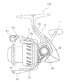
図1に示すように、本発明の第1実施形態によるスピニングリール100は、釣り糸を前方に繰り出し可能なリールである。図1及び図2に示すように、スピニングリール100は、ハンドル1と、ハンドル1を回転自在に支持するリール本体2と、ロータ3と、スプール4とを備えている。
<First Embodiment>
As shown in FIG. 1, the spinning
ハンドル1は、リール本体2に回転自在に装着される。ハンドル1はリール本体2の左右いずれにも装着可能である。
The
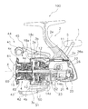
リール本体2は、側部が開口する筐体部2a(図2を参照)と、筐体部2aの側部を覆う蓋部材2bと、筐体部2aの後部に装着されるガード部材26と、を備える。
The
筐体部2aには、上部に前後に延びるT字形の釣り竿装着部2eが、一体形成されている。筐体部2aの内部には、図2に示すように、ロータ駆動機構5と、オシレーティング機構6とが、設けられている。筐体部2aの前縁部は、開口している。蓋部材2bは、筐体部2aの側部の開口を塞ぐために、筐体部2aに着脱可能に装着される。蓋部材2bは、例えば、図示しない固定ボルトにより、筐体部2aに固定されている。
A T-shaped fishing
ガード部材26は、筐体部2a及び蓋部材2bを覆うように後方から装着される部材である。ガード部材26は、例えば、ボス部26aを介して、筐体部2aに固定されている。ガード部材26は、リール本体2の後部の外形形状を決定している。ガード部材26は、例えば、姿合わせのための図示しないパッキンを介して、釣り竿装着部2eを含む筐体部2a、及び蓋部材2bに装着される。
The
ロータ3は、リール本体2の前部に、回転自在に支持されている。具体的には、ロータ3は、後述するピニオンギア12に一体回転可能に連結される。ロータ3は、逆転防止機構50により、逆転禁止状態と逆転許可状態とに切り換え可能である。逆転防止機構50は、例えば、ローラ型のワンウェイクラッチ51である。この切換操作は、リール本体2の下部に配置された切換レバー52により行える。
The
ロータ3は、円筒部3aと、第1ロータアーム3bと、第2ロータアーム3cとを、有している。円筒部3aと第1ロータアーム3b及び第2ロータアーム3cとは、一体成形されている。第1ロータアーム3b及び第2ロータアーム3cは、円筒部3aの側方に互いに対向して設けられている。
The
第1ロータアーム3bの先端の外周側には、第1ベール支持部材45が揺動自在に装着されている。第1ベール支持部材45の先端には、釣り糸をスプール4に案内するためのラインローラ41が、装着されている。また、第2ロータアーム3cの先端内周側には、第2ベール支持部材42が揺動自在に装着されている。
A first
ラインローラ41と第2ベール支持部材42との間には、線材を略U状に湾曲させた形状のベール43が、固定されている。これらの第1ベール支持部材45、第2ベール支持部材42、ラインローラ41、及びベール43により、釣り糸をスプール4に案内するベールアーム44が、構成される。ベールアーム44は、図2に示す糸案内姿勢とそれから反転した糸開放姿勢との間で揺動自在である。
Between the
スプール4は、釣り糸を外周面に巻き取るものであり、ロータ3の前部に前後移動自在に配置されている。スプール4は、一体成型されている。スプール4は、ロータ3の第1ロータアーム3bと第2ロータアーム3cとの間に配置されている。スプール4は、スプール軸15の先端にドラグ機構60を介して、装着されている。なお、図2の符号Xは、スプール軸15の軸中心を示している。
The
図3に示すように、スプール4は、連結部材40と、スプール本体46と、リング部材8と、固定部材9とを、有している。
As shown in FIG. 3, the
連結部材40は、スプール本体46と固定部材9とを連結するための部材である。連結部材40は、円筒状の本体部40aと、雄ネジ部40bとを、有している。雄ネジ部40bは、本体部40aの外周において、一端側に形成されている。具体的には、雄ネジ部40bは、本体部40aの外周において、本体部40aの前端部から中央部に向けて、形成されている。
The connecting
スプール本体46は、糸巻き胴部4aと、スカート部4b(図2を参照)と、前フランジ部4cと、環状突起4d(環状部の一例)とを、有している。糸巻き胴部4aの外周面には、釣り糸が巻かれる。ここでは、スプール本体46の本体部が、糸巻き胴部4aと、スカート部4b(図2を参照)と、前フランジ部4cとから構成されている。
The
糸巻き胴部4aは、連結部材40の雄ネジ部40bに螺合することによって、連結部材40の外周に配置される。糸巻き胴部4aは、円筒部16aと、第1雌ネジ部16bと、位置決め部16cとを、有している。円筒部16aは、円筒状に形成されている。第1雌ネジ部16bは、糸巻き胴部4aの内周において、糸巻き胴部4aの前端部側に形成されている。より具体的には、第1雌ネジ部16bは、円筒部16aの前部内周側に形成されている。第1雌ネジ部16bは、連結部材40の雄ネジ部40bの中央部側に螺合する。位置決め部16cは、連結部材40を位置決めするためのものである。位置決め部16cは、円筒部16aの内周部から内方に突出して一体に形成されている。位置決め部16cには、連結部材40の後端部が当接可能である。
The
図2に示すように、スカート部4bは、ロータ3の円筒部3aを覆うように、糸巻き胴部4aと一体成形されている。具体的には、スカート部4bは、糸巻き胴部4aの後方において、糸巻き胴部4aと一体形成されている。このスカート部4bは、筒状に形成されている。スカート部4bは、後フランジ部18eと、後フランジ部18eの先端部から後方に突出する円筒部18cとを、有している。後フランジ部18eは、前フランジ部4cの径方向長さと実質的に同一長さになるように、糸巻き胴部4aの後端部から径方向外方に突出している。
As shown in FIG. 2, the
図2及ぶ図3に示すように、前フランジ部4cは、糸巻き胴部4aの前端部から径方向外方に延びている。言い換えると、前フランジ部4cは、糸巻き胴部4aより大径に形成されているおり、糸巻き胴部4aの前端に設けられている。
As shown in FIGS. 2 and 3, the
前フランジ部4cは、本体部4eと、環状突起4dを、有している。本体部4eは、糸巻き胴部4aの前端部から径方向外方に突出している。本体部4eは、糸巻き胴部4aと一体成形されており、糸巻き胴部4aの前端部と滑らかに連結されている。
The
環状突起4dは、前フランジ部4cの本体部4eの前側に一体に形成されている。詳細には、環状突起4dは、前フランジ部4cの本体部4eから前方に突出している。環状突起4dは、塑性変形可能である。具体的には、環状突起4dの少なくとも一部は、押圧力により塑性変形する。より具体的には、環状突起4dの少なくとも一部は、押圧力によって、カシメられる。以下では、環状突起4dがカシメられた部分(塑性変形した部分)を、カシメ部4k(塑性変形部の一例、係合部の一例)と呼ぶ。カシメ部4kは、リング部材8の凹部8a(後述する図4及び図5を参照)に係合する。環状突起4dの外周部には、リング部材8が配置される。
The
リング部材8は、釣り糸を前方に案内するためのものである。リング部材8は、前フランジ部4cの外周部に、配置され固定される。具体的には、リング部材8が環状突起4dの外周部に配置された状態において、環状突起4d(凹部8aに隣接しない部分)をカシメることによって、リング部材8は、環状突起4dのカシメ部4kと、前フランジ部4c(本体部4e)とによって挟持される。このようにして、リング部材8は、前フランジ部4c(スプール本体46)に固定される。
The
ここで、リング部材8の構成について、詳細に説明しておく。図3〜図5に示すように、リング部材8は、本体部81aと、突出部81bと、段差部81cとを、有している。本体部81aは、円環状に形成されている。突出部81bは、本体部81aの内周側に一体に形成されている。突出部81bは、円環状に形成されている。詳細には、突出部81bの厚さ(軸方向厚さ、スプール軸15に沿う方向の厚さ)が、塑性変形前の環状突起4dの突出高さより、小さくなるように、突出部81bは形成されている。突出部81bの先端部には、前フランジ部4cの環状突起4dが配置され、前フランジ部4cの環状突起4dが係合する。具体的には、突出部81bの先端部は、前フランジ部4cの本体部4eと、前フランジ部4cの環状突起4dのカシメ部4kとによって、挟持される。
Here, the configuration of the
突出部81bは、凹部8aを有している。凹部8aは、突出部81bの内周部(先端部)に形成されている。詳細には、突出部81bの内周部には、2つの凹部8aが形成されている。2つの凹部8aは、互いに対向するように、突出部81bの内周部に形成されている。突出部81bが環状突起4dの外周部に配置された状態において、環状突起4d(凹部8aに隣接する部分)を、カシメた場合に、環状突起4dのカシメ部4kが、凹部8aに係合する。これにより、スプール本体46に対するリング部材8の回転が、規制される。また、環状突起4dのカシメ部4kを凹部8aに係合させた場合、リング部材8を前フランジ部4c(スプール本体46)に固定する効果は、期待できる。なお、ここでは、2つの凹部8aが形成される場合の例を示したが、凹部8aは1つ以上であればよい。
The
段差部81cは、本体部81aの外周側に形成されている。段差部81cには、固定部材9の外周部(後述する傾斜部9aの外周部)が、配置される。より具体的には、段差部81cと固定部材9の外周部(後述する傾斜部9aの外周部)との間に隙間D(図3を参照)が形成されるように、段差部81cには、固定部材9の外周部が配置される。
The
なお、ここでは、段差部81cと固定部材9の外周部との間に隙間Dが形成される場合の例を示したが、固定部材9の外周部が段差部81cを押圧する力が小さければ、この隙間Dは、必ずしも形成する必要はない。隙間Dを形成しない場合は、固定部材9の外周部が段差部81cを押圧する力によって変形しないように、リング部材8及び/又は固定部材9が形成される。
In addition, although the example in case the clearance gap D is formed between the level | step-
固定部材9は、糸巻き胴部4aの前側に配置される。また、固定部材9は、前フランジ部4cの前側に配置される。固定部材9は、連結部材40の雄ネジ部40bに螺合することによって、連結部材40の外周において糸巻き胴部4aの前側に当接する。固定部材9は、当接部9bと、傾斜部9aとを、有している。当接部9bは、糸巻き胴部4aに当接する部分である。当接部9bは、筒状に形成されている。
The fixing
当接部9bは、第2雌ネジ部19bを有している。第2雌ネジ部19bは、当接部9bの内周面に、形成されている。第2雌ネジ部19bは、連結部材40の雄ネジ部40bの前端部側に螺合する。これにより、当接部9bは、連結部材40の外周において、糸巻き胴部4aの前側に当接する。より具体的には、当接部9bは、連結部材40の外周において、前フランジ部4cの前側に当接する。このように、第2雌ネジ部19bが連結部材40の雄ネジ部40bに装着されると、第1雌ネジ部16bと第2雌ネジ部19bとが連続した状態で、第1雌ネジ部16bと第2雌ネジ部19bとが雄ネジ部40bに螺合する。
The
傾斜部9aは、当接部9bの外周部に一体に形成されている。具体的には、傾斜部9aは、前側から後側に向けて拡径するように、当接部9bから径方向外方に突出して形成されている。傾斜部9aの外周部は、リング部材8の前側に配置される。ここでは、傾斜部9aの外周部とリング部材8の前部との間には、隙間Dが形成されている。固定部材9の内周部には、後述するドラグ調整つまみ61の後端部が、収納される。
The
図2に示すように、ドラグ機構60は、スプール4の回転を制動するものであり、スプール軸15の先端に螺合するドラグ調整つまみ61と、ドラグ調整つまみ61により押圧されてスプール4を制動する制動部62とを有している。
As shown in FIG. 2, the
ロータ駆動機構5は、ロータ3を駆動する。ロータ駆動機構5は、駆動軸10と、駆動ギア11と、ピニオンギア12と、を有している。駆動軸10は、図示しない軸受により、リール本体2に回転自在に支持されている。駆動軸10には、ハンドル1が固定されている。駆動ギア11は、駆動軸10に一体、又は駆動軸10に別体で、設けられる。ここでは、駆動ギア11は、フェースギアの形態になっている。ピニオンギア12は、駆動ギア11に噛み合う部材である。ピニオンギア12は、筒状に形成されており、ピニオンギア12の前部はロータ3の中心部を貫通し、ナット13を介してロータ3に固定されている。また、ピニオンギア12は、その軸方向の中間部と後端部とが、それぞれ軸受14a、14bを介してリール本体2に回転自在に支持されている。
The
オシレーティング機構6は、スプール4を駆動する。オシレーティング機構6は、ドラグ機構60を介して、スプール4の中心部に連結されたスプール軸15を、前後方向に移動させて、スプール4を同方向に移動させるための機構である。オシレーティング機構6は、トラバースカム軸21と、スライダ22と、中間ギア23とを有している。トラバースカム軸21は、スプール軸15の下方において、スプール軸15に平行に配置されている。スライダ22は、トラバースカム軸21に沿って前後方向に移動する。スライダ22には、スプール軸15の後端が回転不能に固定されている。中間ギア23は、トラバースカム軸21の先端に固定されている。中間ギア23は、ピニオンギア12に噛み合っている。
The
<スプール前部の組み立て>
ここでは、スプール4の前部を組み立てる手順について、説明する。まず、リング部材8が、スプール本体46の前フランジ部4cの前側に配置される。詳細には、リング部材8が、スプール本体46の前フランジ部4cの前側において環状突起4dの外周部に、配置される。
<Assembly of the spool front>
Here, the procedure for assembling the front portion of the
次に、この状態において、環状突起4dに押圧力が加えられ、環状突起4dがカシメられる。すると、リング部材8は、環状突起4dのカシメ部4kと、前フランジ部4cとによって挟持される。詳細には、リング部材8の凹部8aに係合しないカシメ部4kは、スプール本体46(前フランジ部4c)に対するリング部材8の固定に、用いられる。一方で、リング部材8の凹部8aに係合するカシメ部4kは、主に、スプール本体46に対するリング部材8の回転規制に、用いられる。また、リング部材8の凹部8aに係合するカシメ部4kは、スプール本体46(前フランジ部4c)に対するリング部材8の固定にも、用いられる。
Next, in this state, a pressing force is applied to the
<まとめ>
(1)本スピニングリール100のスプール4は、釣り糸を前方に繰り出すリールである。スプール4は、スプール本体46と、リング部材8とを、備えている。スプール本体46は、本体部(糸巻き胴部4a、スカート部4b、及び前フランジ部4c)と、環状突起4dとを、有している。環状突起4dは、本体部4a,4b,4cの前側、例えば前フランジ部4cの前側に、一体に形成されている。環状突起4dは、塑性変形可能である。リング部材8は、環状突起4dの外周部に配置される。リング部材8は、環状突起4dの少なくとも一部を押圧力により塑性変形させることによって、環状突起4dのカシメ部4k(塑性変形部)と、前フランジ部4cとによって挟持される。
<Summary>
(1) The
このスプール4では、固定部材9が、リング部材8をスプール本体46に固定するための部材ではなく、スプール本体46の前部を塞ぐ蓋部材として用いられている。このため、固定部材9は、リング部材8に当接させる必要がない。すなわち、固定部材9、リング部材8、及びスプール本体46によって囲まれた空間は、密閉空間とはならない。このため、この空間(≠密閉空間)には、海水等のような異物が、滞留しにくくなり、スプール本体46の腐食を抑制することができる。すなわち、このスプール4では、スプール4の耐久性を向上することができる。
In the
また、固定部材9を蓋部材として用いた場合、固定部材9はリング部材8を押圧する必要がないので、リング部材8から反力を受けることがない。このため、固定部材9を樹脂等で形成したとしても、固定部材9の変形や破断を防止することができる。すなわち、このスプール4では、スプールの耐久性を向上することができる。
Further, when the fixing
(2)本スピニングリール100のスプール4は、リング部材8が、凹部8aを有している。凹部8aは、リング部材8の内周部に形成されている。スプール本体46は、凹部8aに係合するカシメ部4kを、有している。カシメ部4kを凹部8aに係合させることによって、スプール本体46に対するリング部材8の回転が、規制される、
この場合、リング部材8の凹部8aに対して、スプール本体46のカシメ部4kが、係合する。これにより、スプール本体46に対するリング部材8の回転が、規制される。すなわち、凹部8aにカシメ部4kを係合させるだけで、スプール本体46に対する、リング部材8の回転とリング部材8の固定とを、同時に実現することができる。
(2) As for the
In this case, the
(3)本スピニングリール100は、リール本体と、ハンドルと、ロータと、スプール4とを、備えている。ハンドルは、リール本体に回転自在に装着される。ロータは、ハンドルの操作に連動して回転する。スプール4には、ロータの回転によって、釣り糸が巻き付けられる。スプール4には、前記第1実施形態のスプール4である。
(3) The
このスピニングリール100では、スプールが、前記第1実施形態のスプール4を、有している。これにより、本スピニングリール100は、スプールの耐久性を向上することができる。
In the
<第2実施形態>
本発明の第2実施形態によるスピニングリール200は、釣り糸を前方に繰り出し可能なリールである。第2実施形態のスピニングリール200は、スプール104の構成を除いては、第1実施形態に示したスピニングリール100の構成と同じである。このため、ここでは、第1実施形態のスピニングリール100と同じ構成については、説明を省略し、第1実施形態のスピニングリール100と異なる構成についてのみ、説明する。なお、ここで説明を省略した部分については、第1実施形態の内容に準ずるものとする。
Second Embodiment
The spinning
図6に示すように、スプール104は、釣り糸を外周面に巻き取るものであり、ロータ103の前部に前後移動自在に配置されている。スプール104は、スプール本体141と、リング部材108と、固定部材109と、スプール本体141と固定部材109とを連結する連結部材40(図3を参照)とを、有している。
As shown in FIG. 6, the
スプール本体141は、糸巻き胴部104aと、スカート部104bと、前フランジ部104cと、環状突起104d(図8A及び図8Bを参照)とを、有している。ここでは、スプール本体141の本体部が、糸巻き胴部104aと、スカート部104bと、前フランジ部104cとから構成されている。
The spool
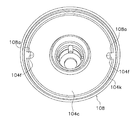
図7、図8A、及び図8Bに示すように、前フランジ部104cは、糸巻き胴部104aの前端部から径方向外方に延びている。前フランジ部104cは、糸巻き胴部104aと一体成形されている。前フランジ部104cは、環状突起104d(図8A、及び図8Bを参照)、及び凹部104f(図7を参照)を、有している。なお、図7は、環状突起104dをカシメた後の図(塑性変形させた後の図)である。
As shown in FIGS. 7, 8A, and 8B, the
図8A及び図8Bに示すように、環状突起104dは、前フランジ部104cの前側に、一体に形成されている。詳細には、環状突起104dは、前フランジ部104cから前方に突出している。環状突起104dは、凹部104fが形成された部分には形成されていない。環状突起104dは、塑性変形可能である。具体的には、環状突起104dの少なくとも一部は、押圧力により塑性変形する。より具体的には、図7に示すように、環状突起104dの全ての部分(凹部104fが形成されていない部分)が、押圧力によって、カシメられる。以下では、環状突起104dがカシメられた部分(塑性変形した部分)を、カシメ部104k(塑性変形部の一例、係合部の一例)と呼ぶ。環状突起104dの外周部には、リング部材108が配置される。
As shown in FIGS. 8A and 8B, the
図7及び図9に示すように、凹部104fは、前フランジ部104cの外周部に形成されている。詳細には、前フランジ部104cの外周部には、2つの凹部104fが形成されている。2つの凹部104fは、互いに対向するように、前フランジ部104cの外周部に形成されている。2つの凹部104fそれぞれには、リング部材108の凸部108a(後述する)が係合する。具体的には、凹部104fには、リング部材108の凸部108aが嵌合される。これにより、スプール本体141に対するリング部材108の位置決めが、行われ、スプール本体141に対するリング部材108の回転が、規制される。なお、ここでは、2つの凹部104fが形成される場合の例を示したが、凹部104fは1つ以上であればよい。
As shown in FIGS. 7 and 9, the
リング部材108は、釣り糸を前方に案内するためのものである。リング部材108は、前フランジ部104cの外周部に、配置され固定される。図7及び図9に示すように、リング部材108は、前フランジ部104cの凹部104fに係合する凸部108aを、有している。凸部108aは、リング部材108の内周部に形成されている。詳細には、リング部材108の内周部には、2つの凸部108aが形成されている。2つの凸部108aは、互いに対向するように、リング部材108の内周部に形成されている。2つの凸部108aそれぞれは、前フランジ部104cの凹部104fに、嵌合される。これにより、スプール本体141に対するリング部材108の位置決めが、行われる。すなわち、スプール本体141に対するリング部材108の回転が、規制される。この状態において、図7に示すように、環状突起104dを周方向に連続的にカシメることによって、リング部材108は、環状突起104dのカシメ部104kと、前フランジ部104cとによって挟持される。このようにして、リング部材108は、前フランジ部104c(スプール本体141)に固定される。
The
<スプール前部の組み立て>
ここでは、スプール104の前部を組み立てる手順について、説明する。まず、リング部材108が、スプール本体141の前フランジ部104cの前側に配置される。詳細には、リング部材108の2つの凸部108aそれぞれを、前フランジ部104cの凹部104fに嵌合することによって、リング部材108が前フランジ部104cの前側において環状突起104dの外周部に、配置される。これにより、リング部材108は、スプール本体141(前フランジ部104c)に対して、位置決めされる。
<Assembly of the spool front>
Here, a procedure for assembling the front portion of the
次に、この状態において、前フランジ部104cの環状突起104dに押圧力が加えられ、環状突起104dがカシメられる。詳細には、前フランジ部104cの環状突起104dに沿って押圧力が連続的に加えられ、環状突起104d全体がカシメられる。これにより、リング部材108が、前フランジ部104cの環状突起104dのカシメ部104kと、前フランジ部104cとによって挟持される。このようにして、リング部材108は、スプール本体141(前フランジ部104c)に対して、回転が規制され、且つ固定される。
Next, in this state, a pressing force is applied to the
<まとめ>
(1)本スプール104は、スプール本体141と、リング部材108とを、備えている。スプール本体141は、本体部(糸巻き胴部104a、スカート部104b、及び前フランジ部104c)と、環状突起104dとを、有している。環状突起104dは、本体部の前側、例えば前フランジ部104cの前側に、一体に形成されている。環状突起104dは、塑性変形可能である。リング部材108は、環状突起104dの外周部に配置される。リング部材108は、環状突起104dを押圧力により塑性変形させることによって、環状突起104dのカシメ部104k(塑性変形部)と、前フランジ部104cとによって挟持される。
<Summary>
(1) The
このスプール104では、前記第1実施形態と同様に、固定部材109をリング部材108に当接させる必要がないので、固定部材109、リング部材108、及びスプール本体141が、密閉空間を形成しない。このため、海水等のような異物が、滞留しにくくなり、スプール本体141の腐食を抑制することができる。すなわち、このスプール104では、スプールの耐久性を向上することができる。
In the
また、ここでは、固定部材109が蓋部材として用いられているので、固定部材109はリング部材108を押圧する必要がない。このため、固定部材109は、リング部材108から反力を受けることがない。このため、固定部材109を樹脂等で形成したとしても、固定部材109の変形を防止することができる。すなわち、このスプール104では、スプールの軽量化及びスプールの耐久性を、同時に向上することができる。
Here, since the fixing member 109 is used as a lid member, the fixing member 109 does not need to press the
(2)本スプール104では、スプール本体141(前フランジ部104c)が、凹部104fを有している。凹部104fは、スプール本体(前フランジ部104c)の外周部に、形成されている。リング部材108は、凹部104fに係合する凸部108aを、有している。凸部108aを凹部104fに係合させることによって、スプール本体141に対するリング部材108の回転が、規制される。これにより、スプール本体141の環状突起104dをカシメることによって(塑性変形させることによって)、スプール本体141に対する、リング部材108の回転とリング部材108の固定とを、同時に実現することができる。
(2) In the
(3)本スピニングリールは、第1実施形態のスピニングリール100と同様に、リール本体と、ハンドル101と、ロータ103と、スプール104とを、備えている。このスピニングリール200では、スプールが、前記第2実施形態のスプール104を、有している。これにより、本スピニングリール200は、スプールの耐久性を向上することができる。
(3) The spinning reel includes a reel main body, a
<他の実施形態>
以上、本発明の一実施形態について説明したが、本発明は上記実施形態に限定されるものではなく、発明の要旨を逸脱しない範囲で種々の変更が可能である。特に、本明細書に書かれた複数の実施形態及び変形例は必要に応じて、任意に組合せ可能である。
<Other embodiments>
As mentioned above, although one Embodiment of this invention was described, this invention is not limited to the said embodiment, A various change is possible in the range which does not deviate from the summary of invention. In particular, a plurality of embodiments and modifications described in the present specification can be arbitrarily combined as necessary.
(A)前記第1実施形態では、リング部材8に2つの凹部8aを形成することによって、スプール本体46に対するリング部材8の回転が、規制される場合の例を、示したが、凹部8aの個数は、どのようにしてもよい。一般的に記載すると、リング部材8は、少なくとも1つの凹部8aが、形成されていれば、スプール本体46に対するリング部材8の回転を、規制することができる。
(A) In the first embodiment, the example in which the rotation of the
(B)前記第1実施形態では、凹部8aに隣接する環状突起4dの一部と、凹部8aに隣接しない環状突起4dの一部とが、カシメられる場合の例を示したが、凹部8aに隣接する環状突起4dの一部だけを、カシメるようにしてもよい。この場合においても、スプール本体46に対するリング部材8の固定、及びスプール本体46に対するリング部材8の回転規制を、同時に実現することができる。
(B) In the first embodiment, an example in which a part of the
(C)前記第1実施形態及び前記第2実施形態では、固定部材9,109が用いられる場合の例を示したが、固定部材9,109を使用しないスピニングリール100,200に対しても、本発明は適用できる。
(C) In the first embodiment and the second embodiment, the example in which the fixing
(D)前記第1実施形態及び前記第2実施形態では、連結部材40が用いられる場合を示した。これに代えて、連結部材40と糸巻き胴部4a,104aとが一体となるように、糸巻き胴部4a,104aを形成してもよい。例えば、糸巻き胴部4a,104aから前方に延びる円筒部(連結部材40に対応)を、糸巻き胴部4a,104aと一体に形成するようにしてもよい。この場合、この円筒部の外周部には、雄ネジ部(第1実施形態の雄ネジ部40bの前部に対応)が形成される。この雄ネジ部に、固定部材9の第2雌ネジ部19bを螺合することによって、前記第1実施形態及び第2実施形態と同様の構成を、得ることができる。すなわち、この構成であっても、前記第1実施形態及び前記第2実施形態と同様の効果を、得ることができる。
(D) In the said 1st Embodiment and the said 2nd Embodiment, the case where the
(E)前記第1実施形態及び第2実施形態に記載された環状突起4d,104dは、次のように構成してもよい。図10に示すように、前フランジ部204cから前方に所定の間隔を隔てた位置において、環状突起204dの外周部にV字状の溝部204gを形成してもよい。このように、V字状の溝部204gを環状突起204dの外周部に形成することによって、この溝部204gを基点として、環状突起204dを外周側に容易に塑性変形させることができる。
(E) The
(F)前記第1実施形態及び第2実施形態に記載された環状突起4d,104dは、次のように構成してもよい。図10に示すように、環状突起4d,104dの内周部と、前フランジ部4c,104cの前部とがなす角度αが、鈍角になるように、環状突起4d,104dを形成してもよい。言い換えると、環状突起4d,104dの先端部における半径方向の厚さd1が、環状突起の基端部における半径方向の厚さd2より、薄くなるように、環状突起4d,104dを形成してもよい。これにより、環状突起4d,104dの先端部を、容易に塑性変形させることができる。
(F) The
(G)前記第1実施形態及び第2実施形態に記載された前フランジ部4c,104cは、次のように構成してもよい。環状突起4d,104dを基準として、前フランジ部4c,104cにおける径方向内側の部分の厚みh1が、前フランジ部4c,104cにおける径方向外側の部分の厚みh2より、厚くなるように、前フランジ部4c,104cを形成してもよい。これにより、環状突起4d,104dに押圧力が加えられた場合に、前フランジ部4c,104cの径方向内側の部分の変形、例えば前後方向への面外変形を、防止することができる。
(G) The
本発明は、スピニングリールのスプール、及びスピニングリールに対して、広く適用可能である。 The present invention is widely applicable to spinning reel spools and spinning reels.
100 スピニングリール
1 ハンドル
2 リール本体
3 ロータ
4 スプール
46 スプール本体
4a 糸巻き胴部
8 リング部材
9 固定部材
9a 傾斜部
9b 当接部
16b 第1雌ネジ部
19b 第2雌ネジ部
40 連結部材
40a 本体部
40b 雄ネジ部
100
46 spool body
4 a
Claims (9)
本体部と、前記本体部の前側に一体に形成され塑性変形可能である環状部とを、有するスプール本体と、
前記環状部の外周部に配置され、前記環状部の少なくとも一部を押圧力により塑性変形させることによって、前記環状部の塑性変形部と前記本体部とによって挟持されるリング部材と、
を備えるスピニングリールのスプール。 A spinning reel spool that feeds fishing line forward,
A spool body having a main body portion and an annular portion integrally formed on the front side of the main body portion and capable of plastic deformation;
A ring member disposed on the outer peripheral portion of the annular portion and sandwiched between the plastic deformation portion of the annular portion and the main body portion by plastically deforming at least a part of the annular portion by a pressing force;
Spinning reel spool with
前記リング部材及びスプール本体のいずれか他方は、前記凹部に係合する係合部を、有しており、
前記係合部を前記凹部に係合させることによって、前記スプール本体に対する前記リング部材の回転が、規制される、
請求項1に記載のスピニングリールのスプール。 One of the ring member and the spool body has a recess,
The other of the ring member and the spool body has an engaging portion that engages with the recess,
By engaging the engagement portion with the recess, rotation of the ring member relative to the spool body is restricted.
The spinning reel spool according to claim 1.
前記係合部は、前記環状部の前記塑性変形部である、
請求項2に記載のスピニングリールのスプール。 The recess is formed in the inner periphery of the ring member,
The engagement portion is the plastic deformation portion of the annular portion.
The spool of the spinning reel according to claim 2.
前記リング部材は、前記凹部に係合する凸部を、有している、
請求項2に記載のスピニングリールのスプール。 The recess is formed in the spool body;
The ring member has a convex portion that engages with the concave portion,
The spool of the spinning reel according to claim 2.
請求項1から4のいずれか1項に記載のスピニングリールのスプール。 A groove is formed in the outer peripheral portion of the annular portion at a position spaced a predetermined distance forward from the main body portion.
The spinning reel spool according to any one of claims 1 to 4.
請求項1から5のいずれか1項に記載のスピニングリールのスプール。 The inner peripheral part of the annular part is formed so that the angle formed by the inner peripheral part of the annular part and the front part of the main body part becomes an obtuse angle,
The spinning reel spool according to any one of claims 1 to 5.
請求項1から6のいずれか1項に記載のスピニングリールのスプール。 On the basis of the annular portion, the radially inner portion of the main body portion is thicker in the front-rear direction than the radially outer portion of the main body portion.
The spinning reel spool according to any one of claims 1 to 6.
請求項1から7のいずれか1項に記載のスピニングリールのスプール。 The ring member is fixed to the spool body by caulking at least a part of the annular portion.
The spinning reel spool according to any one of claims 1 to 7.
前記リール本体に回転自在に装着されるハンドルと、
前記ハンドルの操作に連動して回転するロータと、
前記ロータの回転によって釣り糸が巻き付けられる、請求項1から8のいずれか1項に記載のスプールと、
を備えるスピニングリール。
The reel body,
A handle rotatably mounted to said reel body,
A rotor that rotates in conjunction with the operation of the handle;
The spool according to any one of claims 1 to 8, wherein a fishing line is wound by rotation of the rotor;
Spinning reel with.
Priority Applications (7)
| Application Number | Priority Date | Filing Date | Title |
|---|---|---|---|
| JP2012277878A JP6046481B2 (en) | 2012-12-20 | 2012-12-20 | Spinning reel and spinning reel spool |
| KR1020130093198A KR102054240B1 (en) | 2012-12-20 | 2013-08-06 | Spinning reel and spool for spinning reel |
| TW102133982A TWI606782B (en) | 2012-12-20 | 2013-09-18 | Spinning reel and spinning reel reels |
| US14/045,139 US9226486B2 (en) | 2012-12-20 | 2013-10-03 | Spinning reel and spinning reel spool |
| MYPI2013702034A MY161678A (en) | 2012-12-20 | 2013-10-25 | Spinning reel and spinning reel spool |
| EP13192761.8A EP2745685B1 (en) | 2012-12-20 | 2013-11-13 | Spinning reel and spinning reel spool |
| CN201310707417.7A CN103875622B (en) | 2012-12-20 | 2013-12-20 | The reel of spinning wheel type reel and spinning wheel type reel |
Applications Claiming Priority (1)
| Application Number | Priority Date | Filing Date | Title |
|---|---|---|---|
| JP2012277878A JP6046481B2 (en) | 2012-12-20 | 2012-12-20 | Spinning reel and spinning reel spool |
Publications (3)
| Publication Number | Publication Date |
|---|---|
| JP2014121279A JP2014121279A (en) | 2014-07-03 |
| JP2014121279A5 JP2014121279A5 (en) | 2016-02-04 |
| JP6046481B2 true JP6046481B2 (en) | 2016-12-14 |
Family
ID=50945013
Family Applications (1)
| Application Number | Title | Priority Date | Filing Date |
|---|---|---|---|
| JP2012277878A Active JP6046481B2 (en) | 2012-12-20 | 2012-12-20 | Spinning reel and spinning reel spool |
Country Status (6)
| Country | Link |
|---|---|
| US (1) | US9226486B2 (en) |
| JP (1) | JP6046481B2 (en) |
| KR (1) | KR102054240B1 (en) |
| CN (1) | CN103875622B (en) |
| MY (1) | MY161678A (en) |
| TW (1) | TWI606782B (en) |
Families Citing this family (3)
| Publication number | Priority date | Publication date | Assignee | Title |
|---|---|---|---|---|
| JP6419020B2 (en) * | 2015-04-28 | 2018-11-07 | グローブライド株式会社 | Fishing spinning reel |
| JP6968685B2 (en) * | 2017-12-20 | 2021-11-17 | 株式会社シマノ | Fishing reel spool and fishing reel |
| JP7143116B2 (en) * | 2018-05-18 | 2022-09-28 | シマノコンポネンツ マレーシア エスディーエヌ.ビーエッチディー. | spinning reel |
Family Cites Families (20)
| Publication number | Priority date | Publication date | Assignee | Title |
|---|---|---|---|---|
| JPS5955476U (en) * | 1982-10-04 | 1984-04-11 | ダイワ精工株式会社 | Fishing spinning reel spool |
| JPS6336267U (en) * | 1986-08-25 | 1988-03-08 | ||
| US5785266A (en) * | 1996-11-08 | 1998-07-28 | Bowersox; Ross W. | Variable diameter fishing line reel flange |
| JP3522526B2 (en) * | 1998-02-26 | 2004-04-26 | ダイワ精工株式会社 | Spinning reel for fishing |
| JP2002000136A (en) * | 2000-06-26 | 2002-01-08 | Shimano Inc | Spool for spinning reel |
| JP2002204640A (en) * | 2001-01-10 | 2002-07-23 | Shimano Inc | Spool of spinning reel |
| TW518203B (en) | 2001-01-10 | 2003-01-21 | Shimano Kk | Spool of spinning reel |
| JP2003259772A (en) * | 2002-03-13 | 2003-09-16 | Shimano Inc | Spool of spinning reel |
| JP4025211B2 (en) * | 2002-10-01 | 2007-12-19 | リンナイ株式会社 | Drop-in stove |
| JP4029027B2 (en) * | 2002-11-21 | 2008-01-09 | 株式会社シマノ | Spinning reel spool |
| JP2008005713A (en) * | 2006-06-27 | 2008-01-17 | Shimano Inc | Connection member of fishing reel |
| US7401748B2 (en) * | 2006-12-19 | 2008-07-22 | Shimano Inc. | Spool assembly for spinning reel |
| JP4863928B2 (en) * | 2007-05-21 | 2012-01-25 | 株式会社シマノ | Spinning reel spool |
| JP4943401B2 (en) * | 2007-12-18 | 2012-05-30 | 株式会社シマノ | Fishing reel guide mechanism for spinning reel |
| JP4963291B2 (en) * | 2007-12-27 | 2012-06-27 | 株式会社シマノ | Fishing reel spool |
| JP5279320B2 (en) * | 2008-04-03 | 2013-09-04 | 愛三工業株式会社 | Fuel pump |
| JP2010227007A (en) * | 2009-03-27 | 2010-10-14 | Shimano Inc | Spool ring of spinning reel |
| JP5746462B2 (en) * | 2009-08-20 | 2015-07-08 | 株式会社シマノ | Spinning reel spool connection structure |
| JP5349348B2 (en) * | 2010-01-22 | 2013-11-20 | 株式会社シマノ | Spool support structure for spinning reel |
| JP3176699U (en) * | 2012-04-19 | 2012-06-28 | 隆 大塚 | Spinning reel spool |
-
2012
- 2012-12-20 JP JP2012277878A patent/JP6046481B2/en active Active
-
2013
- 2013-08-06 KR KR1020130093198A patent/KR102054240B1/en active IP Right Grant
- 2013-09-18 TW TW102133982A patent/TWI606782B/en active
- 2013-10-03 US US14/045,139 patent/US9226486B2/en active Active
- 2013-10-25 MY MYPI2013702034A patent/MY161678A/en unknown
- 2013-12-20 CN CN201310707417.7A patent/CN103875622B/en active Active
Also Published As
| Publication number | Publication date |
|---|---|
| MY161678A (en) | 2017-05-15 |
| KR102054240B1 (en) | 2020-01-22 |
| JP2014121279A (en) | 2014-07-03 |
| TWI606782B (en) | 2017-12-01 |
| CN103875622A (en) | 2014-06-25 |
| US9226486B2 (en) | 2016-01-05 |
| US20140175206A1 (en) | 2014-06-26 |
| KR20140080406A (en) | 2014-06-30 |
| TW201424584A (en) | 2014-07-01 |
| CN103875622B (en) | 2017-11-17 |
Similar Documents
| Publication | Publication Date | Title |
|---|---|---|
| CN103238571B (en) | Spinning-reel | |
| JP5153269B2 (en) | Roller clutch | |
| JP5961407B2 (en) | Spinning reel waterproofing member and spinning reel using the same | |
| JP2007054016A (en) | Reel body of spinning reel | |
| US11937592B2 (en) | Waterproof structure and spinning reel | |
| JP2006217848A (en) | Handle assembly for spinning reel | |
| JP6046481B2 (en) | Spinning reel and spinning reel spool | |
| US8882014B2 (en) | Fishing-reel reel unit and fishing reel | |
| JP2014121279A5 (en) | ||
| TWI821239B (en) | Spinning reel | |
| JP6352618B2 (en) | Spinning reel | |
| US7926756B2 (en) | Spinning reel drag knob | |
| JP2015097492A5 (en) | ||
| US7198218B2 (en) | Brake operation structure for fishing reel spool | |
| JP4476128B2 (en) | Spinning reel master gear | |
| JP6110128B2 (en) | Spinning reel and spinning reel spool | |
| EP2745685B1 (en) | Spinning reel and spinning reel spool | |
| JP2008035817A (en) | Spool for spinning reel | |
| JP4827242B2 (en) | Fishing spinning reel | |
| JP2006246794A5 (en) | ||
| JP6449695B2 (en) | Spinning reel | |
| JP2020103118A5 (en) | ||
| JP2006296204A (en) | Drag mechanism of spinning reel | |
| JP2006296204A5 (en) | ||
| JP2009022167A (en) | Spinning reel rotor |
Legal Events
| Date | Code | Title | Description |
|---|---|---|---|
| A521 | Request for written amendment filed |
Free format text: JAPANESE INTERMEDIATE CODE: A523 Effective date: 20151214 |
|
| A621 | Written request for application examination |
Free format text: JAPANESE INTERMEDIATE CODE: A621 Effective date: 20151214 |
|
| A977 | Report on retrieval |
Free format text: JAPANESE INTERMEDIATE CODE: A971007 Effective date: 20161014 |
|
| TRDD | Decision of grant or rejection written | ||
| A01 | Written decision to grant a patent or to grant a registration (utility model) |
Free format text: JAPANESE INTERMEDIATE CODE: A01 Effective date: 20161025 |
|
| A61 | First payment of annual fees (during grant procedure) |
Free format text: JAPANESE INTERMEDIATE CODE: A61 Effective date: 20161117 |
|
| R150 | Certificate of patent or registration of utility model |
Ref document number: 6046481 Country of ref document: JP Free format text: JAPANESE INTERMEDIATE CODE: R150 |
|
| R250 | Receipt of annual fees |
Free format text: JAPANESE INTERMEDIATE CODE: R250 |
|
| R250 | Receipt of annual fees |
Free format text: JAPANESE INTERMEDIATE CODE: R250 |
|
| R250 | Receipt of annual fees |
Free format text: JAPANESE INTERMEDIATE CODE: R250 |
|
| R250 | Receipt of annual fees |
Free format text: JAPANESE INTERMEDIATE CODE: R250 |
|
| R250 | Receipt of annual fees |
Free format text: JAPANESE INTERMEDIATE CODE: R250 |