JP6234589B2 - Axial flow fan and air conditioner having the axial flow fan - Google Patents
Axial flow fan and air conditioner having the axial flow fan Download PDFInfo
- Publication number
- JP6234589B2 JP6234589B2 JP2016540221A JP2016540221A JP6234589B2 JP 6234589 B2 JP6234589 B2 JP 6234589B2 JP 2016540221 A JP2016540221 A JP 2016540221A JP 2016540221 A JP2016540221 A JP 2016540221A JP 6234589 B2 JP6234589 B2 JP 6234589B2
- Authority
- JP
- Japan
- Prior art keywords
- rib
- rotation axis
- propeller fan
- reinforcing rib
- blade
- Prior art date
- Legal status (The legal status is an assumption and is not a legal conclusion. Google has not performed a legal analysis and makes no representation as to the accuracy of the status listed.)
- Active
Links
Images


Classifications
-
- F—MECHANICAL ENGINEERING; LIGHTING; HEATING; WEAPONS; BLASTING
- F04—POSITIVE - DISPLACEMENT MACHINES FOR LIQUIDS; PUMPS FOR LIQUIDS OR ELASTIC FLUIDS
- F04D—NON-POSITIVE-DISPLACEMENT PUMPS
- F04D29/00—Details, component parts, or accessories
- F04D29/26—Rotors specially for elastic fluids
- F04D29/32—Rotors specially for elastic fluids for axial flow pumps
- F04D29/325—Rotors specially for elastic fluids for axial flow pumps for axial flow fans
- F04D29/329—Details of the hub
-
- F—MECHANICAL ENGINEERING; LIGHTING; HEATING; WEAPONS; BLASTING
- F04—POSITIVE - DISPLACEMENT MACHINES FOR LIQUIDS; PUMPS FOR LIQUIDS OR ELASTIC FLUIDS
- F04D—NON-POSITIVE-DISPLACEMENT PUMPS
- F04D29/00—Details, component parts, or accessories
- F04D29/26—Rotors specially for elastic fluids
- F04D29/32—Rotors specially for elastic fluids for axial flow pumps
- F04D29/34—Blade mountings
-
- F—MECHANICAL ENGINEERING; LIGHTING; HEATING; WEAPONS; BLASTING
- F04—POSITIVE - DISPLACEMENT MACHINES FOR LIQUIDS; PUMPS FOR LIQUIDS OR ELASTIC FLUIDS
- F04D—NON-POSITIVE-DISPLACEMENT PUMPS
- F04D29/00—Details, component parts, or accessories
- F04D29/26—Rotors specially for elastic fluids
- F04D29/32—Rotors specially for elastic fluids for axial flow pumps
- F04D29/38—Blades
- F04D29/384—Blades characterised by form
-
- F—MECHANICAL ENGINEERING; LIGHTING; HEATING; WEAPONS; BLASTING
- F04—POSITIVE - DISPLACEMENT MACHINES FOR LIQUIDS; PUMPS FOR LIQUIDS OR ELASTIC FLUIDS
- F04D—NON-POSITIVE-DISPLACEMENT PUMPS
- F04D29/00—Details, component parts, or accessories
- F04D29/26—Rotors specially for elastic fluids
- F04D29/32—Rotors specially for elastic fluids for axial flow pumps
- F04D29/38—Blades
- F04D29/388—Blades characterised by construction
Landscapes
- Engineering & Computer Science (AREA)
- Mechanical Engineering (AREA)
- General Engineering & Computer Science (AREA)
- Structures Of Non-Positive Displacement Pumps (AREA)
- Air-Conditioning Room Units, And Self-Contained Units In General (AREA)
- Other Air-Conditioning Systems (AREA)
Description
本発明は、複数の翼を備えた軸流ファン、及び、その軸流ファンを有する空気調和機に関するものである。 The present invention relates to an axial fan having a plurality of blades and an air conditioner having the axial fan.
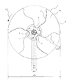
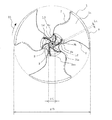
従来の軸流ファンの模式図を図20〜23に示す。
図20は、従来のボス付の軸流ファンの斜視図である。
図21は、従来のボス付の軸流ファンを流体の流れの上流側から見た正面図である。
図22は、従来のボス付の軸流ファンを流体の流れの下流側から見た正面図である。
図23は、従来のボス付の軸流ファンを回転軸線の側方から見た側面図である。Schematic diagrams of conventional axial fans are shown in FIGS.
FIG. 20 is a perspective view of a conventional axial fan with a boss.
FIG. 21 is a front view of a conventional axial fan with a boss as viewed from the upstream side of the fluid flow.
FIG. 22 is a front view of a conventional axial fan with a boss as viewed from the downstream side of the fluid flow.
FIG. 23 is a side view of a conventional axial fan with a boss as viewed from the side of the rotational axis.
従来の軸流ファンは、図20〜23に示すように円筒状のボスの周面に沿って複数枚の翼1を備えており、ボスに与えられる回転力にともなって回転方向11の方向に翼1が回転し、流体の流れ方向10に流体を搬送するものである。このような構成は、例えば特許文献1などにも開示されている。軸流ファンは、翼1が回転することで、翼間に存在している流体が翼面に衝突する。流体が衝突する面は圧力が上昇し、流体を翼1が回転する際の中心軸となる回転軸線方向に押し出して移動させる。
The conventional axial fan includes a plurality of
また、軸流ファンの形状としては、円筒状のボスを有さない、いわゆるボスレスファンが知られている(特許文献2を参照)。ボスレスファンは、複数枚の翼1のうち隣り合う翼の前縁側と後縁側とをボスを介さず連続面で接続した構造をしており、中心にはモータの駆動軸を固定する小径の円筒部を形成したものである。よって、回転軸線を中心とする翼間の連続面の最小半径は、駆動軸を固定する円筒部の半径より大きい寸法となっている。
As an axial fan, a so-called bossless fan that does not have a cylindrical boss is known (see Patent Document 2). The bossless fan has a structure in which the front edge side and the rear edge side of adjacent blades among a plurality of
このような従来のボスを備えた軸流ファンでは、ボスの重量がかさむため軽量化が難しく、省資源化(環境負荷低減)を進めることが困難である。加えて、ボス部は送風機能を有さないため、ファンの送風効率を向上させることが難しいという問題があった。
これに対していわゆるボスレスファンは、ボスがないため上記問題は軽減されるが、強度不足により回転による遠心力が翼に加わることによる翼の変形量が大きく、翼の形状を維持することができないため送風機能が低下する問題や、台風などの強風を受けてプロペラが高速回転し、遠心力によって翼が破断する問題があった。また、回転軸線近傍の肉厚を増やして強度を確保すると、ボスレス化のメリットである軽量化の効果を損なうこととなっていた。In the axial fan having such a conventional boss, the weight of the boss is heavy, so it is difficult to reduce the weight, and it is difficult to save resources (reducing environmental load). In addition, since the boss portion does not have a blowing function, there is a problem that it is difficult to improve the blowing efficiency of the fan.
In contrast, a so-called bossless fan reduces the above problem because it has no boss, but due to insufficient strength, the amount of deformation of the wing caused by centrifugal force due to rotation is large, and the shape of the wing can be maintained. There is a problem that the air blowing function is lowered because it cannot be performed, and there is a problem that the propeller rotates at a high speed in response to strong wind such as a typhoon and the blades are broken due to centrifugal force. Moreover, if the thickness in the vicinity of the rotation axis is increased to ensure the strength, the effect of reducing the weight, which is the merit of bosslessness, is impaired.
本発明は、上記のような軸流ファンの課題を解決するためになされたもので、ボスレス化による軸流ファンの軽量化と、翼の強度の維持とを共に実現し、送風効率を向上させることを目的としている。 The present invention has been made in order to solve the above-described problems of the axial fan, and realizes both the weight reduction of the axial fan by bossless and the maintenance of the blade strength, thereby improving the blowing efficiency. The purpose is that.
本発明に係る軸流ファンは、複数の翼が該翼の回転軸線を中心として回転し、流体を搬送する軸流ファンであって、前記複数の翼のそれぞれは、回転方向における前進側の前縁と、前記回転方向における後進側の後縁と、前記前縁と前記後縁とを接続する外周縁と、を有し、前記複数の翼のうち1枚の翼の前記前縁と、該翼の前記前縁に対して前記回転方向に隣接する翼の前記後縁とは、板状の連結部で接続され、前記複数の翼のそれぞれには、前記回転軸線の周囲から前記翼の外周縁に向けて板状の補強リブが少なくとも1枚配置され、前記補強リブは、前記回転軸線を中心とした放射状、または、前記前縁の向きに凸形状となるように形成され、前記複数の翼のうちの1枚に対して前記回転方向の上流側に位置する上流リブと、前記回転方向の下流側に位置する下流リブと、で少なくとも構成され、前記翼が回転した際に、前記下流リブは、前記上流リブが通過しない領域を通過する構成としたものである。
また、本発明に係る軸流ファンは、複数の翼が該翼の回転軸線を中心として回転し、流体を搬送する軸流ファンであって、前記複数の翼のそれぞれは、回転方向における前進側の前縁と、前記回転方向における後進側の後縁と、前記前縁と前記後縁とを接続する外周縁と、を有し、前記複数の翼のうち1枚の翼の前記前縁と、該翼の前記前縁に対して前記回転方向に隣接する翼の前記後縁とは、板状の連結部で接続され、前記複数の翼のそれぞれには、前記回転軸線の周囲から前記翼の外周縁に向けて板状の補強リブが少なくとも1枚配置され、前記補強リブは、前記回転軸線を中心とした放射状、または、前記前縁の向きに凸形状となるように形成され、前記翼と対向する一端側に上辺を有し、前記補強リブの前記上辺の断面形状は、前記回転方向の上流側に形成される第1円弧部と前記回転方向の下流側に形成される第2円弧部とを有し、前記第1円弧部の断面半径は、前記第2円弧部の断面半径よりも大きい。
また、本発明に係る軸流ファンは、複数の翼が該翼の回転軸線を中心として回転し、流体を搬送する軸流ファンであって、前記複数の翼のそれぞれは、回転方向における前進側の前縁と、前記回転方向における後進側の後縁と、前記前縁と前記後縁とを接続する外周縁と、を有し、前記複数の翼のうち1枚の翼の前記前縁と、該翼の前記前縁に対して前記回転方向に隣接する翼の前記後縁とは、板状の連結部で接続され、前記複数の翼のそれぞれには、前記回転軸線の周囲から前記翼の外周縁に向けて板状の補強リブが少なくとも1枚配置され、前記補強リブは、前記回転軸線を中心とした放射状、または、前記前縁の向きに凸形状となるように形成され、前記連結部は、隣接する前記翼の前記前縁から前記後縁に向けて前記流体の搬送方向の上流側に向かって傾斜して形成されている。
また、本発明に係る軸流ファンは、複数の翼が該翼の回転軸線を中心として回転し、流体を搬送する軸流ファンであって、前記複数の翼のそれぞれは、回転方向における前進側の前縁と、前記回転方向における後進側の後縁と、前記前縁と前記後縁とを接続する外周縁と、を有し、前記複数の翼のうち1枚の翼の前記前縁と、該翼の前記前縁に対して前記回転方向に隣接する翼の前記後縁とは、板状の連結部で接続され、前記複数の翼のそれぞれには、前記回転軸線の周囲から前記翼の外周縁に向けて板状の補強リブが少なくとも1枚配置され、前記回転軸線を中心軸とする円筒部が形成され、前記補強リブは、前記回転軸線を中心とした放射状、または、前記前縁の向きに凸形状となるように形成され、前記翼の形状は、該翼の翼弦中心線が前記円筒部の外周面にあたる当接点から前記回転軸線に垂直な方向に垂直面を設けた際に、前記翼弦中心線が前記垂直面よりも流体の搬送方向の下流側に位置する後傾形である。
An axial flow fan according to the present invention is an axial flow fan in which a plurality of blades rotate around the rotation axis of the blades to convey a fluid, and each of the plurality of blades is arranged in front of a forward side in the rotation direction. edge, a trailing edge of the reverse side in the rotational direction, has an outer peripheral edge which connects the trailing edge and the leading edge, said leading edge of one blade of the plurality of blades, the The trailing edge of the blade adjacent to the leading edge of the blade in the rotation direction is connected by a plate-like connecting portion, and each of the plurality of blades is connected to the outside of the blade from the periphery of the rotation axis. towards the periphery the plate-shaped reinforcing ribs are disposed at least one, the reinforcing ribs are radially around the axis of rotation, or is formed to be a convex shape in the direction of the front edge, said plurality of An upstream rib located upstream in the rotational direction relative to one of the blades, and the rotation And downstream ribs positioned at the downstream side of the direction, in at least configuration, when the blade is rotated, said downstream rib is obtained by a structure which passes through the area where the upstream rib does not pass.
The axial flow fan according to the present invention is an axial flow fan in which a plurality of blades rotate around the rotation axis of the blade to convey a fluid, and each of the plurality of blades is a forward side in the rotation direction. A leading edge of the reverse side in the rotation direction, and an outer peripheral edge connecting the leading edge and the trailing edge, and the leading edge of one of the plurality of blades, The blades adjacent to the leading edge of the blade in the rotational direction are connected to each other by a plate-like connecting portion, and each of the plurality of blades is connected to the blade from the periphery of the rotation axis. At least one plate-like reinforcing rib is disposed toward the outer peripheral edge of the substrate, and the reinforcing rib is formed to have a radial shape around the rotation axis or a convex shape toward the front edge, The one end side facing the wing has an upper side, and the cross-sectional shape of the upper side of the reinforcing rib is the A first arc portion formed on the upstream side in the rolling direction and a second arc portion formed on the downstream side in the rotation direction, and a cross-sectional radius of the first arc portion is a cross section of the second arc portion Greater than radius.
The axial flow fan according to the present invention is an axial flow fan in which a plurality of blades rotate around the rotation axis of the blade to convey a fluid, and each of the plurality of blades is a forward side in the rotation direction. A leading edge of the reverse side in the rotation direction, and an outer peripheral edge connecting the leading edge and the trailing edge, and the leading edge of one of the plurality of blades, The blades adjacent to the leading edge of the blade in the rotational direction are connected to each other by a plate-like connecting portion, and each of the plurality of blades is connected to the blade from the periphery of the rotation axis. At least one plate-like reinforcing rib is disposed toward the outer peripheral edge of the substrate, and the reinforcing rib is formed to have a radial shape around the rotation axis or a convex shape toward the front edge, The connecting portion is configured to convey the fluid from the front edge of the adjacent wing toward the rear edge. Inclined toward the upstream side is formed.
The axial flow fan according to the present invention is an axial flow fan in which a plurality of blades rotate around the rotation axis of the blade to convey a fluid, and each of the plurality of blades is a forward side in the rotation direction. A leading edge of the reverse side in the rotation direction, and an outer peripheral edge connecting the leading edge and the trailing edge, and the leading edge of one of the plurality of blades, The blades adjacent to the leading edge of the blade in the rotational direction are connected to each other by a plate-like connecting portion, and each of the plurality of blades is connected to the blade from the periphery of the rotation axis. At least one plate-like reinforcing rib is disposed toward the outer peripheral edge of the sheet, and a cylindrical portion having the rotation axis as a center axis is formed. The reinforcement rib is formed radially around the rotation axis, or the front It is formed to have a convex shape in the direction of the edge, and the shape of the wing is a chord centerline of the wing When a vertical surface is provided in a direction perpendicular to the rotation axis from a contact point corresponding to the outer peripheral surface of the cylindrical portion, the chord centerline is a rearward inclined shape that is located downstream of the vertical surface in the fluid conveyance direction. It is.
本発明に係る軸流ファンによれば、ボスレス化による軸流ファンの軽量化と、翼の強度の維持とを共に実現するとともに、補強リブによる送風機能を付加して、送風効率を向上させることができる。
なお、以降に記載の「プロペラファン」は「軸流ファン」の一例として記載する。According to the axial fan according to the present invention, both the weight reduction of the axial fan by bosslessness and the maintenance of the strength of the blades are realized, and the blowing function by the reinforcing rib is added to improve the blowing efficiency. Can do.
The “propeller fan” described below is described as an example of the “axial fan”.
実施の形態1.
図1〜5において実施の形態1におけるプロペラファンの構造を説明する。
図1は、実施の形態1に係るプロペラファンを流体流れ方向の上流側から見た正面図である。
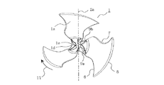
図2は、実施の形態1に係るプロペラファンを流体流れ方向の下流側から見た正面図である。
図3は、実施の形態1に係るプロペラファンを流体流れ方向の下流側から見た斜視図である。
図4は、実施の形態1に係るプロペラファンを流体流れ方向の側方側から見た斜視図である。
図5は、実施の形態1に係るプロペラファンを流体流れ方向の側方側から見た側面図である。
図6は、実施の形態1に係るプロペラファンの補強リブにおける断面図である。
図7は、実施の形態1に係るプロペラファンの補強リブにおける比較用断面図である。
The structure of the propeller fan in the first embodiment will be described with reference to FIGS.
FIG. 1 is a front view of the propeller fan according to
FIG. 2 is a front view of the propeller fan according to the first embodiment when viewed from the downstream side in the fluid flow direction.
FIG. 3 is a perspective view of the propeller fan according to the first embodiment when viewed from the downstream side in the fluid flow direction.
FIG. 4 is a perspective view of the propeller fan according to the first embodiment when viewed from the side in the fluid flow direction.
FIG. 5 is a side view of the propeller fan according to the first embodiment when viewed from the side in the fluid flow direction.
6 is a cross-sectional view of the reinforcing rib of the propeller fan according to
FIG. 7 is a cross-sectional view for comparison in the reinforcing rib of the propeller fan according to the first embodiment.
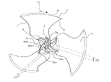
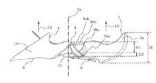
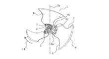
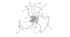
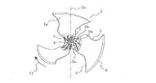
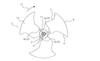
<プロペラファンの全体構成>
実施の形態1のプロペラファンは、回転軸線2aを中心軸として回転する。プロペラファンは、モータの駆動軸が係合する円筒形状の軸孔部2と、軸孔部2を支持する円筒部3とが回転軸線2aの周囲に形成され、円筒部3の外壁面に複数の翼1を固定した形状をしている。軸孔部2と円筒部3との間には、複数の結合リブ4が形成されている。
当該プロペラファンは、樹脂等で形成され、例えば射出成型等で成型される。プロペラファンの樹脂は、例えばポリプロピレンにガラス強化繊維とマイカ(雲母)を混ぜて強度を強くした材料等が使われる。従って、微細なガラスや石が混ざっている材料からポリプロピレン樹脂だけを分離することは容易ではなくリサイクルが困難であり、省資源化を進めるためには、出来る限り材料の使用量を削減することが望ましい。
翼1は、プロペラファンが回転する際の中心軸となる回転軸線2aに対して所定角度傾いて形成されており、プロペラファンの回転に伴って翼間に存在している流体を翼面で押して流体の流れ方向10に搬送する。この際、翼面のうち流体を押して圧力が上昇する面を圧力面1aとし、圧力面1aの裏面で圧力が下降する面を負圧面1bとする。<Overall configuration of propeller fan>
The propeller fan of the first embodiment rotates about the
The propeller fan is formed of resin or the like, and is formed by, for example, injection molding or the like. As the propeller fan resin, for example, a material in which a glass reinforcing fiber and mica (mica) are mixed with polypropylene to increase the strength is used. Therefore, it is not easy to separate only polypropylene resin from materials mixed with fine glass and stone, and it is difficult to recycle. In order to save resources, the amount of materials used should be reduced as much as possible. desirable.
The
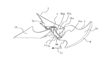
翼1は、翼1の回転方向11における前進側の前縁6と、翼1の回転方向11における後進側の後縁7と、翼1の外周にあたる外周縁8により形状が規定されている。
円筒部3の周囲における複数の翼1の間は、図1、2に示すように各翼1の前縁6と後縁7とを接続する連結部1cにより滑らかに接続されている。そして、回転軸線2aと連結部1cの周縁との最短距離を半径とする破線で示すような円形状の最小半径部1dが形成される。すなわち、回転軸線2aの周囲には、回転軸線2aと連結部1cの周縁との最短距離を半径とする最小半径部1dが形成され、最小半径部1dには、回転軸線2aを中心軸とし、最小半径部1dの半径よりも小さい外周半径を有する円筒部3が形成されている。
よって、回転軸線2aを中心とした最小半径部1dの半径は、円筒部3の外径の半径よりも大きい寸法となっている。このプロペラファンの形状をいわゆるボスレスファンという。
連結部1cは、特に図5に示すように隣接する翼1の前縁6から翼1の後縁7に向けて回転軸線2aと平行な流体の流れ方向10側に傾斜して設けられている。The shape of the
The plurality of
Therefore, the radius of the
In particular, as shown in FIG. 5, the connecting
円筒部3は、図5に示すように流体の流れ方向10の下流側である翼1の圧力面1a側の長さh1が負圧面1b側の長さh2より長く形成されている。また、円筒部3の外壁面と翼1の圧力面1a側との間には補強リブ9が立設されている。
As shown in FIG. 5, the
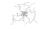
<補強リブ9の構成>
補強リブ9は、例えば翼1の圧力面1aに回転軸線2aと平行に立設された板状部材である。補強リブ9は、円筒部3の外周面と複数の翼1とを接続して形成されている。補強リブ9を回転軸線2a方向から見た正面視の形状は、図2に示すようにプロペラファンの前縁6側に凸形となるように湾曲して(ターボ翼形状)構成されている。
補強リブ9は、1枚の翼1に対して例えば2枚(上流リブ9a、下流リブ9b)配置されている。上流リブ9aはプロペラファンの回転方向11における前進側に配置されており、下流リブ9bはプロペラファンの回転方向11における後進側に配置されている。<Configuration of reinforcing
The reinforcing
For example, two reinforcing ribs 9 (
上流リブ9aと下流リブ9bとは、翼1との接続部分に対向する一端側に上辺9ah、9bhとを有している。上流リブ9aと下流リブ9bの形状は、図5に示すように上流リブ9aの上辺9ahが回転軸線2a方向に対して傾斜しており、下流リブ9bの上辺9bhが軸孔部2の回転軸線2a方向に対して略垂直となるように形成されている。上流リブ9aの上辺9ahの傾斜は、プロペラファンの外周に向かう程、流体の流れ方向10の上流側に向かうように傾斜している。
The
上流リブ9aの上辺9ahと翼1の圧力面1aとの接点である上流リブ接点9asと、下流リブ9bの上辺9bhと翼1の圧力面1aとの接点である下流リブ接点9bsとは、回転軸線2aに対して略同心円上に配置されている。
また、上流リブ接点9asと下流リブ接点9bsとは、翼1の前縁6近傍と、翼1の後縁7近傍に配置されており、翼1を支えている。
また、上流リブ接点9asは、下流リブ接点9bsよりも流体の流れ方向10の上流側に位置している。
また、円筒部3の外周面と上流リブ9aの上辺9ahとの交点は、円筒部3の外周面と下流リブ9bの上辺9bhとの交点と回転軸線2a方向で同一の位置となっている。An upstream rib contact 9as that is a contact point between the upper side 9ah of the
Further, the upstream rib contact 9as and the downstream rib contact 9bs are disposed in the vicinity of the
Further, the upstream rib contact 9as is located on the upstream side in the
Moreover, the intersection of the outer peripheral surface of the
<補強リブ9の断面形状>
上流リブ9aの上辺9ahと下流リブ9bの上辺9bhの断面形状は、図6に示すように、プロペラファンの回転方向11の前縁側と後縁側とで2つの第1円弧9c1と第2円弧9c2とで形成されている。
ここで、前縁側の第1円弧9c1の断面半径r1が、後縁側の第2円弧9c2の断面半径r2よりも大きい半径で規定されている。
なお、図7には、図6との比較のため、第1円弧9c1と第2円弧9c2とを同一断面半径rとした場合の気流の流れを示した。<Cross-sectional shape of reinforcing
As shown in FIG. 6, the cross-sectional shapes of the upper side 9ah of the
Here, the cross-sectional radius r1 of the first arc 9c1 on the front edge side is defined by a radius larger than the cross-sectional radius r2 of the second arc 9c2 on the rear edge side.
For comparison with FIG. 6, FIG. 7 shows the flow of airflow when the first arc 9c1 and the second arc 9c2 have the same cross-sectional radius r.
また、軸孔部2にはD形状断面を有する駆動軸が挿入され固定されるが、円筒部3の外壁面における翼1の間には、駆動軸のDカットにおける水平部の位置を示す印部3aが突起形状もしくは溝形状で形成されている。
In addition, a drive shaft having a D-shaped cross section is inserted and fixed in the
<プロペラファンの各部位の寸法>
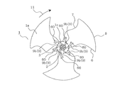
また、図1において、プロペラファンの翼1の最大外径寸法をφDとし、軸孔部2の外径寸法をφAとすると、φA/φDの値を0.02以上0.05以下となるようにφAを設定することが好ましい。
また、図1において、プロペラファンの翼1の最大外径寸法をφDとし、円筒部3の外径寸法をφBとすると、φB/φDの値を0.05以上0.15以下となるようにφBを設定することが好ましい。
さらに、図1において、プロペラファンの翼1の最大外径寸法をφDとし、結合リブ4の長さ寸法をL1(軸孔部2の外周面と円筒部3の内周面との長さ)とすると、L1/φDの値が0.01以上0.05以下となるようにL1を設定することが好ましい。
このような寸法に結合リブ4の長さ寸法L1を設定することで、結合リブ4を構成する樹脂材料が、モータの駆動軸の電磁気振動を低減する振動減衰効果を発揮することができる。<Dimensions of each part of propeller fan>
Further, in FIG. 1, when the maximum outer diameter of the
In FIG. 1, when the maximum outer diameter of the
Further, in FIG. 1, the maximum outer diameter dimension of the
By setting the length L1 of the
また、図2において、プロペラファンの翼1の最大外径寸法をφDとし、円筒部3の外径寸法をφCとすると、φC/φDの値を0.05以上0.15以下となるようにφCを設定することが好ましい。
また、図2において、プロペラファンの翼1の最大外径寸法をφDとし、上流リブ9aの径方向長さ寸法をL2(回転軸線2aと上流リブ接点9asとの長さ)とすると、L2/φDの値が0.1以上0.2以下となるようにL2を設定することが好ましい。
また、図2において、プロペラファンの翼1の最大外径寸法をφDとし、下流リブ9bの径方向長さ寸法をL3(回転軸線2aと下流リブ接点9bsとの長さ)とすると、L3/φDの値が0.1以上0.2以下となるようにL3を設定することが好ましい。
さらに、図2において、プロペラファンの翼1の最大外径寸法をφDとし、結合リブ4の長さ寸法をL4(軸孔部2の外周面と円筒部3の内周面との長さ)とすると、L4/φDの値が0.01以上0.05以下となるようにL4を設定することが好ましい。
このような寸法に結合リブ4の長さ寸法L4を設定することで、結合リブ4を構成する樹脂材料が、モータの駆動軸の電磁気振動を低減する振動減衰効果を発揮することができる。In FIG. 2, when the maximum outer diameter of the
In FIG. 2, when the maximum outer diameter dimension of the
In FIG. 2, if the maximum outer diameter of the
Further, in FIG. 2, the maximum outer diameter of the
By setting the length L4 of the
また、図3において、プロペラファンの翼1の最大外径寸法をφDとし、上流リブ9aの回転軸線2a方向の長さをL5とすると、L5/φDの値を0.05以上0.15以下となるようにL5を設定することが好ましい。
また、図3において、プロペラファンの翼1の最大外径寸法をφDとし、下流リブ9bの回転軸線2a方向の長さをL6とすると、L6/φDの値を0.05以上0.15以下となるようにL5を設定することが好ましい。In FIG. 3, when the maximum outer diameter of the
In FIG. 3, when the maximum outer diameter of the
また、図5において、プロペラファンの翼1の最大外径寸法をφDとし、円筒部3の圧力面1a側の長さをh1とすると、h1/φDの値を0.05以上0.2以下となるようにh1を設定することが好ましい。
また、図5において、プロペラファンの翼1の最大外径寸法をφDとし、円筒部3の負圧面1b側の長さをh2とすると、h2/φDの値を0.1以下となるようにh2を設定することが好ましい。In FIG. 5, when the maximum outer diameter dimension of the
Further, in FIG. 5, when the maximum outer diameter dimension of the
また、図6において、プロペラファンの翼1の最大外径寸法をφDとし、上流リブ9a及び下流リブ9bの厚さ寸法をL7とすると、L7/φDの値を0.0025以上0.025以下となるようにL7を設定することが好ましい。
In FIG. 6, when the maximum outer diameter dimension of the
<気流の流れ>
次に、実施の形態1に係るプロペラファンが回転した際の気流の流れについて図8、図24〜26を用いて説明する。
図8は、実施の形態1に係るプロペラファンにより形成される気流を示した回転軸線方向の風向図である。
図24は、従来のボス付のプロペラファンにより形成される気流を下流側から見た正面視での速度成分を示した説明図である。
図25は、従来のボス付のプロペラファンにより形成される気流の回転軸線方向の速度成分を示した説明図である。
図26は、従来のボス付のプロペラファンにより形成される気流を示した回転軸線方向の風向図である。<Airflow>
Next, the flow of the airflow when the propeller fan according to
FIG. 8 is a wind direction diagram in the rotation axis direction illustrating the airflow formed by the propeller fan according to the first embodiment.
FIG. 24 is an explanatory diagram showing velocity components in a front view when an airflow formed by a conventional propeller fan with a boss is viewed from the downstream side.
FIG. 25 is an explanatory diagram showing velocity components in the direction of the rotation axis of the airflow formed by a conventional propeller fan with a boss.
FIG. 26 is a wind direction diagram in the rotation axis direction showing an air flow formed by a conventional propeller fan with a boss.
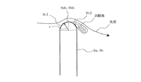
プロペラファンでは、吹き出し気流の外周側に強い遠心力が働くため、吹き出し気流20の吹き出し角度αは正の値(プラス)であり、図8のようにハの字に広がる吹き出し気流となる。
ここで、従来のボス付のプロペラファンの気流成分は図24、25に示すようになっており、吹き出し風速を回転系座標(r、θ、z)座標に分解して考えると、半径方向の風速成分をVr、回転方向11の風速成分をVθ、プロペラファンの回転軸線2a方向の風速成分をVzと定義することができる。In the propeller fan, since a strong centrifugal force acts on the outer peripheral side of the blown airflow, the blowout angle α of the blown
Here, the airflow components of a conventional propeller fan with a boss are as shown in FIGS. 24 and 25. When the blowing air velocity is decomposed into rotation system coordinates (r, θ, z) coordinates, The wind speed component can be defined as Vr, the wind speed component in the
プロペラファンは、回転軸線2a方向に送風することが目的であるため、風速成分Vzのみが送風される風量に相当する。つまり、回転の外周方向に向かって広がるVr成分と、回転しているVθ成分は送風に関与していないため、吹き出された後は最終的に空気中の熱に変換されてエネルギーは消滅してしまう。よって、風速成分Vzを相対的に増やすことが送風効率を高めることとなり、電動機の消費電力の削減に貢献する。
また、図26に示すように回転軸線2a方向に吹き出した風は、回転軸線2a周囲ではプロペラファンに向けて逆流することが実測から明らかになっている。Since the propeller fan is intended to blow air in the direction of the
In addition, as shown in FIG. 26, it is clear from actual measurements that the wind blown in the direction of the
実施の形態1に係るプロペラファンが回転した際の気流の流れは図8に示すようになっている。
圧力面1aから搬送された吹き出し気流20は、半径方向の速度成分をVr、回転方向11の速度成分をVθ、プロペラファンの回転軸線2a方向の速度成分をVzとしてそれらが合成された風向Vとなって吹き出される。The flow of the airflow when the propeller fan according to
The blown
そして、プロペラファンの回転軸線2a部分では、吹き出し気流20に対して逆向きの気流21が生じ、プロペラファンの中心部に向けて逆流する。逆向きの気流21は、補強リブ9の回転によって作り出された負圧によって、旋回流となってプロペラファンの回転軸線2a方向に強制的に吸引される。この吸引作用は、補強リブ9の形状がプロペラファンの前縁6側に凸となる形状(ターボ翼形状)となっているため、ターボファンによる吸引側の気流と同じ効果を奏するためである。
And in the
プロペラファンの回転軸線2a方向に強制的に吸引された空気は、補強リブ9の圧力面で翼1の外周方向に反転気流23のように押し出され、翼1の圧力面1a上に流入する。すると、プロペラファンの回転軸線2a付近に負圧域が形成され、逆向きの気流21の流れを強くする効果をもたらす。
また、補強リブ9の高さは、上記のように上流リブ9aよりも下流リブ9bの方が高く構成されているため、上流リブ9aに衝突しなかった空気は下流リブ9bに衝突して、翼1の外周方向に移動し反転気流23となって、圧力面1a上に流入する。
そして、翼と翼の間を通過して通常に圧力面1aに流入した流入気流22と合流して吹き出し気流20方向に吹き出される。The air that is forcibly sucked in the direction of the
Further, since the height of the reinforcing
And it joins with the
ここで、補強リブ9の吸引効果を明確にするため、吸引効果の全くない従来のボス付きプロペラファンと気流を比較する。
従来のボス付きのプロペラファンの場合、図26に示すように、ボスの近傍で停滞していた流れは吹き出し気流20に誘引され循環している。これに対して実施の形態1に係るプロペラファンの場合、図8に示すように、補強リブ9があるため回転軸線2a付近に負圧を発生して逆向きの気流21を吸込むので、吹き出し気流20を回転軸線2a方向に竜巻のように巻き込み、吹き出し気流20の吹き出し角度αを小さくする効果を有する。すなわち、実施の形態1に係るプロペラファンの吹き出し角度α2は、従来のボス付プロペラファンの吹き出し角度α1よりも小さくなる。
回転軸線2a方向の風速成分Vz=COSα・Vであるため、吹き出し角度αが小さくなるほど吹き出し気流20の風向が閉じて、回転軸線2a方向の風速成分Vzを増加させ、送風効率を高めることができる。風速成分Vzが相対的に増えると、プロペラファンで同一風量を発生させるための回転数を下げることができるため、消費電力を削減することが可能となる。Here, in order to clarify the suction effect of the reinforcing
In the case of a conventional propeller fan with a boss, as shown in FIG. 26, the flow stagnating in the vicinity of the boss is attracted by the blowing
Since the wind speed component Vz in the direction of the
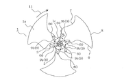
<変形例1>
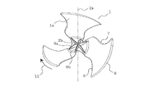
図9は、実施の形態1の変形例1に係るプロペラファンを流体流れ方向の下流側から見た正面図である。
上記実施の形態1に係るプロペラファンの説明では、補強リブ9の回転軸線2a方向からの正面視の形状を翼1の前縁6側に凸形となるターボ翼形状としたが、変形例1に係る補強リブ9は、図9に示すようにプロペラファンの回転軸線2aに対し放射状に伸びる直線状の平板形状となっている。
このような放射状の平板形状の補強リブ9としても、ターボ翼形状より若干弱いが補強リブ9の回転によって作り出された負圧によって、プロペラファンの回転軸線2a方向に気流を強制的に吸引させる効果を有する。よって、吹き出し角度αを小さくして回転軸線2a方向の風速成分Vzを増加させ、送風効率を高めることができる。<
FIG. 9 is a front view of the propeller fan according to the first modification of the first embodiment when viewed from the downstream side in the fluid flow direction.
In the description of the propeller fan according to the first embodiment, the shape of the reinforcing
Such a radial flat plate-shaped reinforcing
<効果>
このように構成された実施の形態1及びその変形例1に係るプロペラファンにおいては、いわゆるボスレス形のプロペラファンにおいて、連結部1cの最小半径部1dよりも小さい半径をもつ円筒部3の外周面から翼1の前縁6と後縁7に向かって補強リブ9を複数伸ばしているので、回転軸線2a付近の逆向きの気流21を補強リブ9が吸引する効果を有する。すると、風速が速くなった逆向きの気流21が吹き出し気流20を回転軸線2a方向に巻き込んで、吹き出し気流20の吹き出し角度αを小さくすることができる。よって、吹き出し気流20の回転軸線2a方向の風速成分Vzを相対的に増加させて、ファンの送風効率を上げることができる。<Effect>
In the propeller fan according to the first embodiment and the
そして、各翼1を連結部1cにより滑らかに接続したことで、翼1に加わる遠心力による応力集中を分散させ、補強リブ9で支持するためボス付きのプロペラファンと同等の翼1の強度を確保し、翼1の変形を抑制して送風効率を向上させることができる。また、翼1の強度が向上するため、プロペラファンが回転した場合において、遠心力によって羽根が変形して送風性能が悪化することを抑制することができる。また、ボス部分に使われていた多くの樹脂を削減し、補強リブ9のみでボス付ファンと同等の強度を確保することができるので、軽量化(省資源化)を達成することができる。
Since each
また、上流リブ9aと下流リブ9bの形状は、図5に示すように上流リブ9aの上辺9ahが軸孔部2の中心軸方向に対して傾斜しており、下流リブ9bの上辺9bhが軸孔部2の中心軸方向に対して略垂直となるように形成されているため、上流リブ9aに当たらなかった気流は下流リブ9bにより翼1の圧力面1aに押し出される。すると、複数の補強リブ9が気流を吸引する効果を一周(360°)で6回(約60°毎)行って全周囲に分散させるので、吸引する負圧の変動を抑制することができ、安定した負圧による吸引効果を得ることができる。
Further, as shown in FIG. 5, the
さらに、図6のように補強リブ9の前縁側の第1円弧9c1の断面半径r1が、後縁側の第2円弧9c2の断面半径r2よりも大きい半径で規定されている。すると、図7に記載の均等断面半径の断面形状に比べて、大きな断面半径r1を持つ第1円弧9c1に沿って流体が滑らかに流れ、後縁側の第2円弧9c2上での気流の剥離渦が抑制される。よって、流体の損失エネルギーが低減されるので、プロペラファンを回転するための駆動力が低減され、モータの消費電力が削減される。
Further, as shown in FIG. 6, the cross-sectional radius r1 of the first arc 9c1 on the front edge side of the reinforcing
また、連結部1cは、特に図4に示すように隣接する翼1の前縁6から翼1の後縁7に向けて流体の流れ方向10に傾斜して設けられているため、連結部1cの圧力面1aに流入した気流をスムーズに補強リブ9に衝突させ、翼1の外周方向に押し出すことが可能になる。
Further, since the connecting
また、円筒部3の外壁面における翼1の間には、駆動軸のDカットにおける水平部の位置を示す印部3aを形成したため、モータの駆動軸にプロペラファンの軸孔部2を挿通する際にプロペラファンの取付方向を特定し易くなり、組み付け時間を短縮し作業効率を向上させることができる。
Further, since the
次に、実施の形態1に係るプロペラファンの補強リブ9がターボ翼形状のときの変形例について説明する。
<変形例2>
図27は、実施の形態1の変形例2に係るプロペラファンの流体流れ方向の下流側から見た斜視図である。
変形例2に係る補強リブ9は、図27に示すように、実施の形態1(図2、図3を参照)に係る上流リブ9aと下流リブ9bとの間に3枚目の中間リブ9cが配置されたものである。
すなわち、補強リブ9は、プロペラファンの前縁6側に凸形となるターボ翼形状であり、1枚の翼1に対して上流リブ9a、中間リブ9c、下流リブ9bが配置されている。
なお、その他の構成は、実施の形態1に係るプロペラファンの構成と同一である。Next, a modification when the reinforcing
<
FIG. 27 is a perspective view of the propeller fan according to the second modification of the first embodiment when viewed from the downstream side in the fluid flow direction.
As shown in FIG. 27, the reinforcing
That is, the reinforcing
Other configurations are the same as those of the propeller fan according to the first embodiment.
<効果>
変形例2では、1枚の翼1に対して3枚の補強リブ9を配置することで実施の形態1に係る1枚の翼1に対して2枚の補強リブ9を配置したプロペラファンに比べて翼1の強度を向上させることができる。また、補強リブが合計で6枚から9枚となることで、回転軸線2a付近の逆向きの気流21を補強リブ9が吸引する効果が大きくなる。よって、吹き出し気流20の回転軸線2a方向の風速成分Vzを相対的に増加させて、ファンの送風効率を上げることができる。<Effect>
In the second modification, a propeller fan in which two reinforcing
<変形例3>
図28は、実施の形態1の変形例3に係るプロペラファンの流体流れ方向の下流側から見た斜視図である。
変形例3に係る補強リブ9は、図28に示すように、実施の形態1に係る円筒部3と軸孔部2と結合リブ4とが形成されておらず、6枚のターボ翼形状の補強リブ9(上流リブ9aと下流リブ9b)同士が回転軸線2aまで延設されて交差し、お互いに結合された構成になっている。すなわち、6枚の補強リブ9同士は、回転軸線2aにおいて交わることで軸線部2bを形成し、軸線部2bと複数の翼1とを接続している。
なお、その他の構成は、実施の形態1に係るプロペラファンの構成と同一である。<
FIG. 28 is a perspective view of the propeller fan according to the third modification of the first embodiment when viewed from the downstream side in the fluid flow direction.
As shown in FIG. 28, the reinforcing
Other configurations are the same as those of the propeller fan according to the first embodiment.
<効果>
変形例3では、実施の形態1に係る円筒部3と軸孔部2と結合リブ4とが形成されていないシンプルな構成ながら、補強リブ9を回転軸線2aまで延設してプロペラファンの翼1の強度を確保することができる。
<変形例4>
図29は、実施の形態1の変形例4に係るプロペラファンの流体流れ方向の下流側から見た斜視図である。
変形例4に係る補強リブ9は、図29に示すように、変形例3に係る上流リブ9aと下流リブ9bとの間に3枚目の中間リブ9cが配置されたものである。
補強リブ9は、プロペラファンの前縁6側に凸形となるターボ翼形状であり、1枚の翼1に対して上流リブ9a、中間リブ9c、下流リブ9bが配置されている。9枚の補強リブ9同士は、回転軸線2aにおいて交わることで軸線部2bを形成し、軸線部2bと複数の翼1とを接続している。
なお、その他の構成は、実施の形態1に係るプロペラファンの構成と同一である。<Effect>
In the third modification example, the reinforcing
<
FIG. 29 is a perspective view of the propeller fan according to the fourth modification of the first embodiment when viewed from the downstream side in the fluid flow direction.
As shown in FIG. 29, the reinforcing
The reinforcing
Other configurations are the same as those of the propeller fan according to the first embodiment.
<効果>
変形例4では、1枚の翼1に対して3枚の補強リブ9を配置することで変形例3に係る1枚の翼1に対して2枚の補強リブ9を配置したプロペラファンに比べて翼1の強度を向上させることができる。また、補強リブが合計で6枚から9枚となることで、回転軸線2a付近の逆向きの気流21を補強リブ9が吸引する効果が大きくなる。よって、吹き出し気流20の回転軸線2a方向の風速成分Vzを相対的に増加させて、ファンの送風効率を上げることができる。<Effect>
In the fourth modification, the three reinforcing
<変形例5>
図30は、実施の形態1の変形例5に係るプロペラファンの流体流れ方向の下流側から見た斜視図である。
変形例5に係る補強リブ9は、図30に示すように、実施の形態1に係る円筒部3と軸孔部2と結合リブ4とが形成されておらず、回転軸線2aの周囲にモータの駆動軸を取り付ける円形開口1eが開口している。6枚のターボ翼形状の補強リブ9(上流リブ9aと下流リブ9b)は、円形開口1eの開口縁まで延設されて形成された構成になっている。
すなわち、回転軸線2aの周囲に、回転軸線2aと連結部1cの周縁との最短距離を半径とする最小半径部1dが形成され、最小半径部1dには、回転軸線2aを中心軸とし、最小半径部1dの半径よりも小さい半径を有する円形開口1eが開口している。そして、補強リブ9は、円形開口1eの開口縁と複数の翼1とを接続している。
なお、その他の構成は、実施の形態1に係るプロペラファンの構成と同一である。<Modification 5>
FIG. 30 is a perspective view of the propeller fan according to the fifth modification of the first embodiment when viewed from the downstream side in the fluid flow direction.
As shown in FIG. 30, the reinforcing
That is, a
Other configurations are the same as those of the propeller fan according to the first embodiment.
<効果>
変形例5では、実施の形態1に係る円筒部3と軸孔部2と結合リブ4とが形成されていないシンプルな構成ながら、補強リブ9を円形開口1eの開口縁まで延設してプロペラファンの翼1の強度を確保することができる。
<変形例6>
図31は、実施の形態1の変形例6に係るプロペラファンの流体流れ方向の下流側から見た斜視図である。
変形例6に係る補強リブ9は、図31に示すように、変形例5に係る上流リブ9aと下流リブ9bとの間に3枚目の中間リブ9cが配置されたものである。
すなわち、補強リブ9は、プロペラファンの前縁6側に凸形となるターボ翼形状であり、1枚の翼1に対して上流リブ9a、中間リブ9c、下流リブ9bが配置されている。
なお、その他の構成は、実施の形態1に係るプロペラファンの構成と同一である。<Effect>
In the modified example 5, although the
<
FIG. 31 is a perspective view of the propeller fan according to the sixth modification of the first embodiment when viewed from the downstream side in the fluid flow direction.
As shown in FIG. 31, the reinforcing
That is, the reinforcing
Other configurations are the same as those of the propeller fan according to the first embodiment.
<効果>
変形例6では、1枚の翼1に対して3枚の補強リブ9を配置することで変形例5に係る1枚の翼1に対して2枚の補強リブ9を配置したプロペラファンに比べて翼1の強度を向上させることができる。また、補強リブが合計で6枚から9枚となることで、回転軸線2a付近の逆向きの気流21を補強リブ9が吸引する効果が大きくなる。よって、吹き出し気流20の回転軸線2a方向の風速成分Vzを相対的に増加させて、ファンの送風効率を上げることができる。<Effect>
In the sixth modification, the three reinforcing
次に、プロペラファンの補強リブ9が回転軸線2aに対し放射状に伸びる直線状の平板形状のときの変形例について説明する。
<変形例7>
図32は、実施の形態1の変形例7に係るプロペラファンの流体流れ方向の下流側から見た斜視図である。
変形例7に係る補強リブ9は、図32に示すように、実施の形態1の変形例1(図9を参照)に係る上流リブ9aと下流リブ9bとの間に3枚目の中間リブ9cが配置されたものである。
すなわち、補強リブ9は、プロペラファンの回転軸線2aに対し放射状に伸びる直線状の平板形状であり、1枚の翼1に対して上流リブ9a、中間リブ9c、下流リブ9bが配置されている。
なお、その他の構成は、実施の形態1に係るプロペラファンの構成と同一である。Next, a description will be given of a modification example in which the reinforcing
<
FIG. 32 is a perspective view of the propeller fan according to the seventh modification of the first embodiment when viewed from the downstream side in the fluid flow direction.
As shown in FIG. 32, the reinforcing
That is, the reinforcing
Other configurations are the same as those of the propeller fan according to the first embodiment.
<効果>
変形例7では、1枚の翼1に対して3枚の補強リブ9を配置することで実施の形態1の変形例1に係る1枚の翼1に対して2枚の補強リブ9を配置したプロペラファンに比べて翼1の強度を向上させることができる。また、補強リブが合計で6枚から9枚となることで、回転軸線2a付近の逆向きの気流21を補強リブ9が吸引する効果が大きくなる。よって、吹き出し気流20の回転軸線2a方向の風速成分Vzを相対的に増加させて、ファンの送風効率を上げることができる。<Effect>
In the modified example 7, two reinforcing
<変形例8>
図33は、実施の形態1の変形例8に係るプロペラファンの流体流れ方向の下流側から見た斜視図である。
変形例8に係る補強リブ9は、図33に示すように、実施の形態1に係る円筒部3と軸孔部2と結合リブ4とが形成されておらず、6枚の回転軸線2aに対し放射状に伸びる直線状の平板形状の補強リブ9(上流リブ9aと下流リブ9b)同士が回転軸線2aまで延設されて交差し、お互いに結合された構成になっている。すなわち、6枚の補強リブ9同士は、回転軸線2aにおいて交わることで軸線部2bを形成し、軸線部2bと複数の翼1とを接続している。
なお、その他の構成は、実施の形態1に係るプロペラファンの構成と同一である。<
FIG. 33 is a perspective view of the propeller fan according to the eighth modification of the first embodiment when viewed from the downstream side in the fluid flow direction.
As shown in FIG. 33, the reinforcing
Other configurations are the same as those of the propeller fan according to the first embodiment.
<効果>
変形例8では、実施の形態1に係る円筒部3と軸孔部2と結合リブ4とが形成されていないシンプルな構成ながら、補強リブ9を回転軸線2aまで延設してプロペラファンの翼1の強度を確保することができる。
<変形例9>
図34は、実施の形態1の変形例9に係るプロペラファンの流体流れ方向の下流側から見た斜視図である。
変形例9に係る補強リブ9は、図34に示すように、変形例8に係る上流リブ9aと下流リブ9bとの間に3枚目の中間リブ9cが配置されたものである。
すなわち、補強リブ9は、プロペラファンの回転軸線2aに対し放射状に伸びる直線状の平板形状であり、1枚の翼1に対して上流リブ9a、中間リブ9c、下流リブ9bが配置されている。9枚の補強リブ9同士は、回転軸線2aにおいて交わることで軸線部2bを形成し、軸線部2bと複数の翼1とを接続している。
なお、その他の構成は、実施の形態1に係るプロペラファンの構成と同一である。<Effect>
In the
<
FIG. 34 is a perspective view of the propeller fan according to the ninth modification of the first embodiment when viewed from the downstream side in the fluid flow direction.
As shown in FIG. 34, the reinforcing
That is, the reinforcing
Other configurations are the same as those of the propeller fan according to the first embodiment.
<効果>
変形例9では、1枚の翼1に対して3枚の補強リブ9を配置することで変形例8に係る1枚の翼1に対して2枚の補強リブ9を配置したプロペラファンに比べて翼1の強度を向上させることができる。また、補強リブが合計で6枚から9枚となることで、回転軸線2a付近の逆向きの気流21を補強リブ9が吸引する効果が大きくなる。よって、吹き出し気流20の回転軸線2a方向の風速成分Vzを相対的に増加させて、ファンの送風効率を上げることができる。<Effect>
In the modified example 9, the three reinforcing
<変形例10>
図35は、実施の形態1の変形例10に係るプロペラファンの流体流れ方向の下流側から見た斜視図である。
変形例10に係る補強リブ9は、図35に示すように、実施の形態1に係る円筒部3と軸孔部2と結合リブ4とが形成されておらず、回転軸線2aの周囲にモータの駆動軸を取り付ける円形開口1eが開口している。6枚の回転軸線2aに対し放射状に伸びる直線状の平板形状の補強リブ9(上流リブ9aと下流リブ9b)は、円形開口1eの開口縁まで延設されて形成された構成になっている。
すなわち、回転軸線2aの周囲に、回転軸線2aと連結部1cの周縁との最短距離を半径とする最小半径部1dが形成され、最小半径部1dには、回転軸線2aを中心軸とし、最小半径部1dの半径よりも小さい半径を有する円形開口1eが開口している。そして、補強リブ9は、円形開口1eの開口縁と複数の翼1とを接続している。
なお、その他の構成は、実施の形態1に係るプロペラファンの構成と同一である。<
FIG. 35 is a perspective view of the propeller fan according to the tenth modification of the first embodiment when viewed from the downstream side in the fluid flow direction.
As shown in FIG. 35, the reinforcing
That is, a
Other configurations are the same as those of the propeller fan according to the first embodiment.
<効果>
変形例10では、実施の形態1に係る円筒部3と軸孔部2と結合リブ4とが形成されていないシンプルな構成ながら、補強リブ9を円形開口1eの開口縁まで延設してプロペラファンの翼1の強度を確保することができる。
<変形例11>
図36は、実施の形態1の変形例11に係るプロペラファンの流体流れ方向の下流側から見た斜視図である。
変形例11に係る補強リブ9は、図36に示すように、変形例10に係る上流リブ9aと下流リブ9bとの間に3枚目の中間リブ9cが配置されたものである。
すなわち、補強リブ9は、プロペラファンの回転軸線2aに対し放射状に伸びる直線状の平板形状であり、1枚の翼1に対して上流リブ9a、中間リブ9c、下流リブ9bが配置されている。
なお、その他の構成は、実施の形態1に係るプロペラファンの構成と同一である。<Effect>
In the
<
FIG. 36 is a perspective view of the propeller fan according to the eleventh modification of the first embodiment when viewed from the downstream side in the fluid flow direction.
As shown in FIG. 36, the reinforcing
That is, the reinforcing
Other configurations are the same as those of the propeller fan according to the first embodiment.
<効果>
変形例11では、1枚の翼1に対して3枚の補強リブ9を配置することで変形例10に係る1枚の翼1に対して2枚の補強リブ9を配置したプロペラファンに比べて翼1の強度を向上させることができる。また、補強リブが合計で6枚から9枚となることで、回転軸線2a付近の逆向きの気流21を補強リブ9が吸引する効果が大きくなる。よって、吹き出し気流20の回転軸線2a方向の風速成分Vzを相対的に増加させて、ファンの送風効率を上げることができる。<Effect>
In the modified example 11, the three reinforcing
なお、補強リブ9は、1枚の翼1に対して2枚や3枚配置する例を示したが4枚以上形成してもよい。
また、翼1の枚数は2枚以上であれば特段制約を受けない。In addition, although the example which arrange | positions two or three
Further, if the number of
実施の形態2.
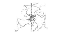
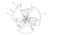
実施の形態2に係るプロペラファンは、実施の形態1に係るプロペラファンと補強リブ9の形状のみが異なるため補強リブ9の構成を説明する。
図10は、実施の形態2に係るプロペラファンの流体流れ方向の下流側から見た例の正面図である。
図10に示すように、実施の形態2に係る補強リブ9の形状は、回転軸線2a方向からの正面視の形状を翼1の後縁7側に凸形となるように湾曲させたシロッコ翼形状となっている。
Since the propeller fan according to the second embodiment is different from the propeller fan according to the first embodiment only in the shape of the reinforcing
FIG. 10 is a front view of an example viewed from the downstream side in the fluid flow direction of the propeller fan according to the second embodiment.
As shown in FIG. 10, the shape of the reinforcing
<効果>
このようなシロッコ翼形状の補強リブ9とすると、補強リブ9の回転によって押された空気が回転軸線2a側に集められるので、軸方向に送風する効果を有する。つまり、翼1の中心部にミニプロペラファンを有するような効果を奏する。よって、回転軸線2a方向の風速成分Vzを増加させ、後述する低圧損の動作点においては送風効率を高めることができる。<Effect>
When such a sirocco blade-shaped reinforcing
ここで、実施の形態1に係る補強リブ9の形状を前縁6側に凸形となるターボ翼形状、及び、放射状に伸びる直線状の平板形状とした場合と、実施の形態2に係る後縁7側に凸形となるように湾曲させたシロッコ翼形状とした場合との効果の相違を説明する。
図11は、プロペラファンの送風性能を示すP−Q線図である。
一般的に、プロペラファンの送風性能は、図11に示すような流体の圧力(静圧)と単位時間あたりの風量の関係(P−Q線図)で表される。プロペラファンの風路に抵抗が多く存在すると、圧力損失カーブが通常圧損曲線Aから高圧損曲線Bへと立ち上がり、プロペラファンの能力特性曲線Cとの交点である動作点も移動することが知られている。高圧損曲線Bは、流路の圧力損失を通常圧損曲線Aの2倍に設定したものである。
通常圧損曲線Aと能力特性曲線Cとの交点が通常動作点となり、高圧損曲線Bと能力特性曲線Cとの交点が高圧損の動作点となり、静圧ゼロと能力特性曲線Cとの交点が低圧損の動作点となる。Here, the shape of the reinforcing
FIG. 11 is a PQ diagram showing the blowing performance of the propeller fan.
In general, the air blowing performance of a propeller fan is represented by the relationship between the fluid pressure (static pressure) and the air volume per unit time (PQ diagram) as shown in FIG. It is known that if there is a lot of resistance in the wind path of the propeller fan, the pressure loss curve rises from the normal pressure loss curve A to the high pressure loss curve B, and the operating point that is the intersection with the propeller fan performance characteristic curve C also moves. ing. The high pressure loss curve B is obtained by setting the pressure loss of the flow path to twice the normal pressure loss curve A.
The intersection of the normal pressure loss curve A and the capacity characteristic curve C is the normal operating point, the intersection of the high pressure loss curve B and the capacity characteristic curve C is the operating point of the high pressure loss, and the intersection of zero static pressure and the capacity characteristic curve C is This is the operating point for low pressure loss.
実施の形態1における補強リブ9の形状を前縁6側に凸形となるターボ翼形状、及び、放射状に伸びる直線状の平板形状とした場合には、補強リブ9の回転によって作り出された負圧によって、プロペラファンの回転軸線2a方向に気流を強制的に吸引するターボ翼の効果により、静圧を必要とする通常動作点や高圧損の動作点となる流路抵抗のある使用条件が適している。
一方、実施の形態2における補強リブ9を後縁7側に凸形となるように湾曲させたシロッコ翼形状とした場合には、補強リブ9の回転によって押された空気が回転軸線2a側に集められるので、補強リブ9が回転軸線2a方向に送風するミニプロペラファンのような効果を有し、静圧を必要とせず風量を必要とする流路抵抗の少ない低圧損の動作点での使用が適している。In the case where the shape of the reinforcing
On the other hand, when the reinforcing
次に、実施の形態2に係るプロペラファンの補強リブ9がシロッコ翼形状のときの変形例について説明する。
<変形例1>
図37は、実施の形態2の変形例1に係るプロペラファンの流体流れ方向の下流側から見た斜視図である。
変形例1に係る補強リブ9は、図37に示すように、実施の形態2(図10を参照)に係る上流リブ9aと下流リブ9bとの間に3枚目の中間リブ9cが配置されたものである。
すなわち、補強リブ9は、プロペラファンの後縁7側に凸形となるシロッコ翼形状であり、1枚の翼1に対して上流リブ9a、中間リブ9c、下流リブ9bが配置されている。
なお、その他の構成は、実施の形態2に係るプロペラファンの構成と同一である。Next, a modification when the reinforcing
<
FIG. 37 is a perspective view of the propeller fan according to the first modification of the second embodiment when viewed from the downstream side in the fluid flow direction.
As shown in FIG. 37, the reinforcing
In other words, the reinforcing
Other configurations are the same as those of the propeller fan according to the second embodiment.
<効果>
変形例1では、1枚の翼1に対して3枚の補強リブ9を配置することで実施の形態2に係る1枚の翼1に対して2枚の補強リブ9を配置したプロペラファンに比べて翼1の強度を向上させることができる。また、補強リブが合計で6枚から9枚となることで、補強リブ9の回転によって押された空気が回転軸線2a側に集められ、回転軸線2a方向に送風する効果が向上する。つまり、翼1の中心部にミニプロペラファンを有するような効果を奏する。よって、回転軸線2a方向の風速成分Vzを増加させ、低圧損の動作点においては送風効率を高めることができる。<Effect>
In the first modification, a propeller fan in which two reinforcing
<変形例2>
図38は、実施の形態2の変形例2に係るプロペラファンの流体流れ方向の下流側から見た斜視図である。
変形例2に係る補強リブ9は、図38に示すように、実施の形態2(図10を参照)に係る円筒部3と軸孔部2と結合リブ4とが形成されておらず、6枚のシロッコ翼形状の補強リブ9(上流リブ9aと下流リブ9b)同士が回転軸線2aまで延設されて交差し、お互いに結合された構成になっている。すなわち、6枚の補強リブ9同士は、回転軸線2aにおいて交わることで軸線部2bを形成し、軸線部2bと複数の翼1とを接続している。
なお、その他の構成は、実施の形態2に係るプロペラファンの構成と同一である。<
FIG. 38 is a perspective view of the propeller fan according to the second modification of the second embodiment when viewed from the downstream side in the fluid flow direction.
As shown in FIG. 38, the reinforcing
Other configurations are the same as those of the propeller fan according to the second embodiment.
<効果>
変形例2では、実施の形態2に係る円筒部3と軸孔部2と結合リブ4とが形成されていないシンプルな構成ながら、補強リブ9を回転軸線2aまで延設してプロペラファンの翼1の強度を確保することができる。
<変形例3>
図39は、実施の形態2の変形例3に係るプロペラファンの流体流れ方向の下流側から見た斜視図である。
変形例3に係る補強リブ9は、図39に示すように、変形例2に係る上流リブ9aと下流リブ9bとの間に3枚目の中間リブ9cが配置されたものである。
すなわち、補強リブ9は、プロペラファンの後縁7側に凸形となるシロッコ翼形状であり、1枚の翼1に対して上流リブ9a、中間リブ9c、下流リブ9bが配置されている。9枚の補強リブ9同士は、回転軸線2aにおいて交わることで軸線部2bを形成し、軸線部2bと複数の翼1とを接続している。
なお、その他の構成は、実施の形態2に係るプロペラファンの構成と同一である。<Effect>
In the second modified example, the reinforcing
<
FIG. 39 is a perspective view of the propeller fan according to the third modification of the second embodiment when viewed from the downstream side in the fluid flow direction.
As shown in FIG. 39, the reinforcing
In other words, the reinforcing
Other configurations are the same as those of the propeller fan according to the second embodiment.
<効果>
変形例3では、1枚の翼1に対して3枚の補強リブ9を配置することで変形例2に係る1枚の翼1に対して2枚の補強リブ9を配置したプロペラファンに比べて翼1の強度を向上させることができる。また、補強リブが合計で6枚から9枚となることで、補強リブ9の回転によって押された空気が回転軸線2a側に集められ、回転軸線2a方向に送風する効果が向上する。つまり、翼1の中心部にミニプロペラファンを有するような効果を奏する。よって、回転軸線2a方向の風速成分Vzを増加させ、低圧損の動作点においては送風効率を高めることができる。<Effect>
In the third modification, the three reinforcing
<変形例4>
図40は、実施の形態2の変形例4に係るプロペラファンの流体流れ方向の下流側から見た斜視図である。
変形例4に係る補強リブ9は、図40に示すように、実施の形態2に係る円筒部3と軸孔部2と結合リブ4とが形成されておらず、回転軸線2aの周囲にモータの駆動軸を取り付ける円形開口1eが開口している。6枚のシロッコ翼形状の補強リブ9(上流リブ9aと下流リブ9b)は、円形開口1eの開口縁まで延設されて形成された構成になっている。
すなわち、回転軸線2aの周囲に、回転軸線2aと連結部1cの周縁との最短距離を半径とする最小半径部1dが形成され、最小半径部1dには、回転軸線2aを中心軸とし、最小半径部1dの半径よりも小さい半径を有する円形開口1eが開口している。そして、補強リブ9は、円形開口1eの開口縁と複数の翼1とを接続している。
なお、その他の構成は、実施の形態2に係るプロペラファンの構成と同一である。<
FIG. 40 is a perspective view of the propeller fan according to the fourth modification of the second embodiment when viewed from the downstream side in the fluid flow direction.
As shown in FIG. 40, the reinforcing
That is, a
Other configurations are the same as those of the propeller fan according to the second embodiment.
<効果>
変形例4では、実施の形態1に係る円筒部3と軸孔部2と結合リブ4とが形成されていないシンプルな構成ながら、補強リブ9を円形開口1eの周縁まで延設してプロペラファンの翼1の強度を確保することができる。
<変形例5>
図41は、実施の形態2の変形例5に係るプロペラファンの流体流れ方向の下流側から見た斜視図である。
変形例5に係る補強リブ9は、図41に示すように、変形例4に係る上流リブ9aと下流リブ9bとの間に3枚目の中間リブ9cが配置されたものである。
すなわち、補強リブ9は、プロペラファンの後縁7側に凸形となるシロッコ翼形状であり、1枚の翼1に対して上流リブ9a、中間リブ9c、下流リブ9bが配置されている。
なお、その他の構成は、実施の形態2に係るプロペラファンの構成と同一である。<Effect>
In the fourth modification, the propeller fan is provided by extending the reinforcing
<Modification 5>
FIG. 41 is a perspective view of the propeller fan according to the fifth modification of the second embodiment when viewed from the downstream side in the fluid flow direction.
As shown in FIG. 41, the reinforcing
In other words, the reinforcing
Other configurations are the same as those of the propeller fan according to the second embodiment.
<効果>
変形例5では、1枚の翼1に対して3枚の補強リブ9を配置することで変形例5に係る1枚の翼1に対して2枚の補強リブ9を配置したプロペラファンに比べて翼1の強度を向上させることができる。また、また、補強リブが合計で6枚から9枚となることで、補強リブ9の回転によって押された空気が回転軸線2a側に集められ、回転軸線2a方向に送風する効果が向上する。つまり、翼1の中心部にミニプロペラファンを有するような効果を奏する。よって、回転軸線2a方向の風速成分Vzを増加させ、低圧損の動作点においては送風効率を高めることができる。<Effect>
In the modified example 5, the three reinforcing
実施の形態3.
実施の形態3は、実施の形態1または2に係るプロペラファンの翼1を流体の流れ方向10に倒した形状(後述する後傾形)とした場合の実施例である。
The third embodiment is an example in which the
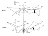
図12は、実施の形態3に係るプロペラファンの正面図に翼弦中心線15の位置を記載した図である。
図13は、実施の形態3に係る後傾形のプロペラファンを前傾形のプロペラファンと比較して側面図に翼弦中心線15の位置を記載した図である。
ここで、翼弦中心線15とは、翼1の特定の円周上における中央点の集合である。
図13において、後傾形の翼1の翼弦中心線15は、円筒部3の外壁面にあたる当接点15aから回転軸線2aに垂直な方向に延びた垂直面16を引くと、翼弦中心線15は垂直面16よりも流体の流れ方向10の下流側に位置している。これに対して、前傾形の翼弦中心線15は垂直面16よりも流体の流れ方向10の上流側に位置している。
よって、実施の形態3に係る後傾形のプロペラファンでは、翼1は、翼弦中心線15が垂直面16よりも流体の流れの下流側に配置される形状を備えている(以降、後傾形という)。FIG. 12 is a diagram illustrating the position of the
FIG. 13 is a side view showing the position of the
Here, the
In FIG. 13, the
Therefore, in the rearwardly inclined propeller fan according to the third embodiment, the
図13で示す翼1上の矢印は、翼1が回転した場合に空気が押される方向であり、後傾形のプロペラファンでは、翼1の内周側に向かって傾斜(=閉じた流れ)している。
比較のため図13の前傾形のプロペラファンでは、後傾形とは逆に、空気が押される方向が翼1の外周側に向かって傾斜(=開いた流れ)している。The arrow on the
For comparison, in the forward inclined propeller fan of FIG. 13, the direction in which air is pushed is inclined toward the outer peripheral side of the blade 1 (= open flow), contrary to the backward inclined type.
次に、図14において、前傾形と後傾形のプロペラファンの回転軸線2aと平行な方向の風速成分Vzの違いについて説明する。
図14は、実施の形態3に係る後傾形のプロペラファンの速度成分25と、前傾形のプロペラファンの速度成分26と、を比較した図である。
風速成分Vzの最も高い(=風量が多い)場所は、空気が翼1に押される方向が異なるため、後傾形の速度成分25は、前傾形の速度成分26よりもピークの位置が翼1の内周側に寄る傾向がある。Next, in FIG. 14, the difference in the wind speed component Vz in the direction parallel to the
FIG. 14 is a diagram comparing the
The place where the wind velocity component Vz is the highest (= the air volume is large) is different in the direction in which the air is pushed by the
図示のように実施の形態3に係る後傾形のプロペラファンは、気流の速度分布が翼1の外周側に広がることを抑えることで、吹き出し気流20の吹き出し角度α(図8で説明したようにαは正の値)を小さくすることができる。
As shown in the drawing, the rearwardly inclined propeller fan according to the third embodiment suppresses the airflow velocity distribution from spreading to the outer peripheral side of the
なお、後傾形の翼弦中心線15が垂直面16よりも流体の流れの下流側に全て配置された翼形状の例を示したが、翼弦中心線15の長さの70%以上が垂直面16よりも流体の流れの下流側に配置されている翼1の形状であれば、上記と同様の機能及び効果を有する。
In addition, although the example of the wing | blade shape in which the backward inclination
<効果>
実施の形態3に係るプロペラファンでは、このように後傾形の翼1を採用することで、実施の形態1に係る効果に加えて、さらに吹き出し気流20の吹き出し角度αを小さくすることができる。よって、吹き出し気流20の回転軸線2a方向の風速成分Vzを相対的に増加させて、ファンの送風効率を上げることができる。<Effect>
In the propeller fan according to the third embodiment, in addition to the effect according to the first embodiment, the blowing angle α of the blowing
実施の形態4.
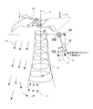
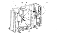
実施の形態4に係るプロペラファンは、実施の形態1〜3に係るプロペラファンを空気調和機の室外機30に採用した実施例である。このプロペラファンは、室外熱交換器31に熱交換用の外気を送風する機能を有する。
図15は、実施の形態4に係る室外機に実施の形態1〜3に係るプロペラファンを取り付けた際の外観斜視図である。
図16は、実施の形態4に係る室外機に実施の形態1〜3に係るプロペラファンを取り付けた際の内部斜視図である。
図17は、実施の形態4に係る室外機のプロペラファンに外風が当たった時の補強リブの作用を説明する図である。
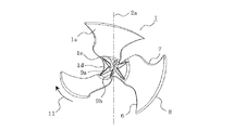
実施の形態4に係る室外機30のプロペラファンは、補強リブ9を回転軸線2a方向から見た正面視の形状で、図2に示すようにプロペラファンの前縁6側に凸形となるように湾曲して構成(ターボ翼形状)されているものである。
The propeller fan according to the fourth embodiment is an example in which the propeller fan according to the first to third embodiments is employed in the
FIG. 15 is an external perspective view when the propeller fan according to the first to third embodiments is attached to the outdoor unit according to the fourth embodiment.
FIG. 16 is an internal perspective view when the propeller fan according to the first to third embodiments is attached to the outdoor unit according to the fourth embodiment.
FIG. 17 is a diagram for explaining the action of the reinforcing rib when the outside wind hits the propeller fan of the outdoor unit according to the fourth embodiment.
The propeller fan of the
この補強リブ9は、実施の形態1に記載したように、通常の回転方向11に回転することで回転軸線2a近傍に負圧域を形成し、吹き出し気流20に対して逆向きの気流21を吸引する。
ここで、実施の形態3に係る室外機30が停止している時にプロペラファンに屋外の強風が当たる場合を考える。この強風は、プロペラファンが通常運転した時に発生させる流体の流れ方向10とは反対向きの逆風としてプロペラファンに作用する。
強風(逆風)は、プロペラファンの圧力面1aに衝突し、通常の回転方向11とは反対回転方向12に翼1を回転させる。すると、通常の回転方向11では回転方向11に凸形状に湾曲して構成(ターボ翼形状)された補強リブ9が、反対回転方向12の時には反対回転方向12に凹形状に湾曲した構成(シロッコ翼形状)となる。As described in the first embodiment, the reinforcing
Here, a case is considered where outdoor strong wind hits the propeller fan when the
The strong wind (back wind) collides with the
<効果>
室外機30に設けたプロペラファンは、屋外の強風(逆風)が当たる時に高速で回転し遠心力で翼1が破断して破損することがある。実施の形態3に係るプロペラファンでは、強風がプロペラファンに当たると、補強リブ9が、反対回転方向12に凹形状に湾曲した構成(シロッコ翼形状)となるため、図15に示す各補強リブ9の間の空間40の空気がパラシュート作用により回転の抵抗となる。したがって、通常の回転方向11では実施の形態1に係る気流の吸引作用を有すると共に、強風による反対回転方向12では、プロペラファンの回転速度を抑制してプロペラファンの破損を防止することができる。<Effect>
The propeller fan provided in the
<プロペラファンの梱包>
実施の形態1〜3における、プロペラファンの梱包について説明する。
図18は、実施の形態1〜3におけるプロペラファンの梱包状態を示す模式図である。
図19は、従来のボス付のプロペラファンの梱包状態を示す模式図である。
図18において、梱包用のダンボール50内にボスレス形のプロペラファンが積層されて収納されており、ダンボール50の底面から翼1の前縁6までは距離Lが確保されているよう台座51が円筒部3の底面を支えるように配置されている。<Packaging of propeller fan>
The packaging of the propeller fan in the first to third embodiments will be described.
FIG. 18 is a schematic diagram showing a packing state of the propeller fan in the first to third embodiments.
FIG. 19 is a schematic view showing a packing state of a conventional propeller fan with a boss.
In FIG. 18, a bossless-type propeller fan is stacked and stored in a
実施の形態1〜3におけるプロペラファンは、従来のボス付プロペラファンにおけるボスの回転軸線方向寸法に比べて円筒部3の軸方向寸法が短いため、図18のように円筒部3の上面と下面とを当接して積層した際に積層方向の寸法を抑制し、梱包用のダンボール50内に従来より多くのプロペラファンを収納することが可能になる。
Since the propeller fan in the first to third embodiments has the axial dimension of the
実施の形態5.
実施の形態1〜4に係るプロペラファンでは、1枚の翼1に対して上流リブ9aと下流リブ9bの2枚の補強リブ9を形成したが、実施の形態5は、1枚の翼1に対して上流リブ9aと下流リブ9bのうち下流リブ9bのみを1枚配置している。その他のプロペラファンの構成は、実施の形態1〜4と同一である。Embodiment 5. FIG.
In the propeller fan according to the first to fourth embodiments, the two reinforcing
図42は、実施の形態5に係るプロペラファンの流体流れ方向の下流側から見た正面図である。
図43は、実施の形態5の変形例1に係るプロペラファンの流体流れ方向の下流側から見た正面図である。
図44は、実施の形態5の変形例2に係るプロペラファンの流体流れ方向の下流側から見た正面図である。FIG. 42 is a front view of the propeller fan according to Embodiment 5 as viewed from the downstream side in the fluid flow direction.
FIG. 43 is a front view of the propeller fan according to the first modification of the fifth embodiment when viewed from the downstream side in the fluid flow direction.
FIG. 44 is a front view of the propeller fan according to the second modification of the fifth embodiment when viewed from the downstream side in the fluid flow direction.
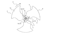
実施の形態5に係るプロペラファンは、例えば図42に示すように翼1の前縁6側に凸形状となるターボ翼形状の補強リブ9を備えたプロペラファンである。補強リブ9は、実施の形態1(図2を参照)に記載の上流リブ9aと下流リブ9bのうち下流リブ9bのみが設置されている。
The propeller fan according to the fifth embodiment is, for example, a propeller fan that includes a turbo blade-shaped reinforcing
<変形例1>
また、実施の形態5の変形例1に係るプロペラファンは、例えば図43に示すように翼1の後縁7側に凸形状となるシロッコ翼形状の補強リブ9を備えたプロペラファンである。補強リブ9は、実施の形態2(図10を参照)に記載の上流リブ9aと下流リブ9bのうち下流リブ9bのみが設置されている。<
Further, the propeller fan according to the first modification of the fifth embodiment is a propeller fan including a reinforcing
<変形例2>
さらに、実施の形態5の変形例2に係るプロペラファンは、例えば図44に示すようにプロペラファンの回転軸線2aに対し放射状に伸びる直線状の平板形状の補強リブ9を備えたプロペラファンである。補強リブ9は、実施の形態1の変形例1(図9を参照)に記載の上流リブ9aと下流リブ9bのうち下流リブ9bのみが設置されている。<
Furthermore, the propeller fan according to the second modification of the fifth embodiment is a propeller fan including linear flat plate-shaped reinforcing
<効果>
実施の形態5及びその変形例1、2に係るプロペラファンは、1枚の翼1に対して下流リブ9bを1枚だけ配置した構成のため、プロペラファンの軽量化が可能となる。また、本実施の形態のプロペラファンは低速回転域の使用に適しており、下流リブ9bのみで翼1を支持しても強度を保つことが可能である。
さらに、実施の形態5及びその変形例1に係るターボ翼形状、及び、放射状に伸びる平板形状の下流リブ9bでは、回転軸線2a付近の逆向きの気流21を吸引する効果を発揮することができる。よって、吹き出し気流20の回転軸線2a方向の風速成分Vzを相対的に増加させて、ファンの送風効率を上げることができる。
また、変形例2に係るシロッコ翼形状の下流リブ9bでは、下流リブ9bの回転によって押された空気が回転軸線2a側に集められ、回転軸線2a方向に送風する効果が向上する。つまり、翼1の中心部にミニプロペラファンを有するような効果を奏する。よって、回転軸線2a方向の風速成分Vzを増加させ、低圧損の動作点においては送風効率を高めることができる。<Effect>
Since the propeller fan according to the fifth embodiment and the first and second modifications thereof has a configuration in which only one
Furthermore, the turbo blade shape according to the fifth embodiment and the modified example 1 and the flat plate-shaped
Further, in the sirocco wing-shaped
実施の形態6.
実施の形態1〜4に係るプロペラファンでは、1枚の翼1に対して上流リブ9aと下流リブ9bの2枚の補強リブ9を形成したが、実施の形態6は、1枚の翼1に対して上流リブ9aと下流リブ9bのうち上流リブ9aのみを1枚配置している。その他のプロペラファンの構成は、実施の形態1〜4と同一である。
In the propeller fan according to the first to fourth embodiments, the two reinforcing
図45は、実施の形態6に係るプロペラファンの流体流れ方向の下流側から見た正面図である。
図46は、実施の形態6の変形例1に係るプロペラファンの流体流れ方向の下流側から見た正面図である。
図47は、実施の形態6の変形例2に係るプロペラファンの流体流れ方向の下流側から見た正面図である。FIG. 45 is a front view of the propeller fan according to
FIG. 46 is a front view of the propeller fan according to the first modification of the sixth embodiment when viewed from the downstream side in the fluid flow direction.
FIG. 47 is a front view of the propeller fan according to the second modification of the sixth embodiment when viewed from the downstream side in the fluid flow direction.
実施の形態6に係るプロペラファンは、例えば図45に示すように翼1の前縁6側に凸形状となるターボ翼形状の補強リブ9を備えたプロペラファンである。補強リブ9は、実施の形態1(図2を参照)に記載の上流リブ9aと下流リブ9bのうち上流リブ9aのみが設置されている。
The propeller fan according to the sixth embodiment is a propeller fan including a turbo wing-shaped reinforcing
<変形例1>
また、実施の形態6の変形例1に係るプロペラファンは、例えば図46に示すように翼1の後縁7側に凸形状となるシロッコ翼形状の補強リブ9を備えたプロペラファンである。補強リブ9は、実施の形態2(図10を参照)に記載の上流リブ9aと下流リブ9bのうち上流リブ9aのみが設置されている。<
Further, the propeller fan according to the first modification of the sixth embodiment is a propeller fan including a reinforcing
<変形例2>
さらに、実施の形態6の変形例2に係るプロペラファンは、例えば図47に示すようにプロペラファンの回転軸線2aに対し放射状に伸びる直線状の平板形状の補強リブ9を備えたプロペラファンである。補強リブ9は、実施の形態1の変形例1(図9を参照)に記載の上流リブ9aと下流リブ9bのうち上流リブ9aのみが設置されている。<
Furthermore, the propeller fan according to the second modification of the sixth embodiment is a propeller fan including linear flat plate-shaped reinforcing
<効果>
実施の形態6及びその変形例1、2に係るプロペラファンは、1枚の翼1に対して上流リブ9aを1枚だけ配置した構成のため、プロペラファンの軽量化が可能となる。また、本実施の形態のプロペラファンは実施の形態3に係るプロペラファンに比べて高速回転域の使用に適しており、翼1への応力が集中する前縁6側に上流リブ9aを配置することで強度を保つことが可能となる。
さらに、実施の形態6及びその変形例1に係るターボ翼形状、及び、放射状に伸びる平板形状の上流リブ9aでは、回転軸線2a付近の逆向きの気流21を吸引する効果を発揮することができる。よって、吹き出し気流20の回転軸線2a方向の風速成分Vzを相対的に増加させて、ファンの送風効率を上げることができる。
また、変形例2に係るシロッコ翼形状の上流リブ9aでは、上流リブ9aの回転によって押された空気が回転軸線2a側に集められ、回転軸線2a方向に送風する効果が向上する。つまり、翼1の中心部にミニプロペラファンを有するような効果を奏する。よって、回転軸線2a方向の風速成分Vzを増加させ、低圧損の動作点においては送風効率を高めることができる。<Effect>
Since the propeller fan according to the sixth embodiment and the first and second modifications thereof has a configuration in which only one
Furthermore, the turbo blade shape according to the sixth embodiment and its modification example 1 and the flat plate-shaped
Further, in the sirocco wing-shaped
なお、実施の形態5、6では、1枚の翼1に対して上流リブ9aと下流リブ9bのうちの一方を配置した例を示したが、1枚の補強リブ9を配置する位置は翼1の前縁6側や後縁7側に近接して配置せず、任意の位置に形成すればよい。すなわち、翼1の前縁6と後縁7との間に収まるように配置されれば任意の位置を採用することが可能である。
In the fifth and sixth embodiments, an example in which one of the
実施の形態7.
実施の形態1〜6に係るプロペラファンでは、板材の厚みが均等な平板形状の補強リブ9を採用した例を示したが、実施の形態7に係る補強リブ9には、翼1の外周縁8側に翼1との接合面積を大きく取る拡開部60が形成されている。
その他のプロペラファンの構成は、実施の形態1〜6と同一である。
In the propeller fan according to the first to sixth embodiments, the example in which the flat plate-shaped reinforcing
The structure of the other propeller fan is the same as in the first to sixth embodiments.
図48は、実施の形態7に係るプロペラファンを流体流れ方向の下流側から見た正面図である。
図49は、実施の形態7の変形例1に係るプロペラファンを流体流れ方向の下流側から見た正面図である。
図50は、実施の形態7の変形例2に係るプロペラファンを流体流れ方向の下流側から見た正面図である。FIG. 48 is a front view of the propeller fan according to the seventh embodiment when viewed from the downstream side in the fluid flow direction.
FIG. 49 is a front view of the propeller fan according to the first modification of the seventh embodiment when viewed from the downstream side in the fluid flow direction.
FIG. 50 is a front view of the propeller fan according to the second modification of the seventh embodiment when viewed from the downstream side in the fluid flow direction.
実施の形態7に係るプロペラファンは、例えば図48に示すように翼1の前縁6側に凸形状となるターボ翼形状の補強リブ9を備えたプロペラファンである。補強リブ9の外周縁8側の端部には、図48に示すように回転軸線2a方向から見て補強リブ9の厚さ方向に向けてY字形状に拡開する拡開部60が形成されている。すなわち、補強リブ9の外周縁8側の端部に、単位長さあたりで翼1との接合面積が増加する拡開部60が形成されている。
For example, as shown in FIG. 48, the propeller fan according to the seventh embodiment is a propeller fan including a turbo blade-shaped reinforcing
拡開部60は、補強リブ9の外周縁8側の端部に補強リブ9と翼1との接合面積が大きくなる形状として形成されれば図48に示すY字形状には限定されない。例えば、補強リブ9の外周縁8側の端部に補強リブ9の厚さ寸法よりも大きい外径寸法の円柱形状や多角柱形状などとして形成することができる。すなわち、拡開部60は、翼1の径方向における単位長さ当たりの翼1と補強リブ9との接合面積で比較したときに、補強リブ9の外周縁8側の端部以外の部分よりも接合面積が大きく形成された部位として定義される。
The expanding
<変形例1>
実施の形態7の変形例1に係るプロペラファンは、例えば図49に示すように翼1の後縁7側に凸形状となるシロッコ翼形状の補強リブ9を備えたプロペラファンである。補強リブ9の外周縁8側の端部には、図49に示すように回転軸線2a方向から見て補強リブ9の厚さ方向に向けてY字形状に拡開する拡開部60が形成されている。すなわち、補強リブ9の外周縁8側の端部に、単位長さあたりで翼1との接合面積が増加する拡開部60が形成されている。拡開部60の形状は上記と同様にこのY字形状には限定されない。<
For example, as shown in FIG. 49, the propeller fan according to the first modification of the seventh embodiment is a propeller fan including a sirocco blade-shaped reinforcing
<変形例2>
さらに、実施の形態7の変形例2に係るプロペラファンは、例えば図50に示すようにプロペラファンの回転軸線2aに対し放射状に伸びる直線状の平板形状の補強リブ9を備えたプロペラファンである。補強リブ9の外周縁8側の端部には、図50に示すように回転軸線2a方向から見て補強リブ9の厚さ方向に向けてY字形状に拡開する拡開部60が形成されている。すなわち、補強リブ9の外周縁8側の端部に、単位長さあたりで翼1との接合面積が増加する拡開部60が形成されている。拡開部60の形状は上記と同様にこのY字形状には限定されない。<
Furthermore, the propeller fan according to the second modification of the seventh embodiment is a propeller fan including linear flat plate-shaped reinforcing
<効果>
実施の形態7及びその変形例1、2に係るプロペラファンは、補強リブ9における翼1の外周縁8側に翼1との接合面積を大きく取る拡開部60が形成されているため、翼1の応力が最も大きく作用する補強リブ9の外周縁8側の端部において応力を分散して受けることができる。すなわち、拡開部60において翼1との接合面積を大きく確保し、翼1からの応力を分散加重として補強リブ9が受けることで補強リブ9と翼1との接合が破断することを防止することができる。特に室外機等で屋外の強風がプロペラファンに当たり、高速回転したときに、羽根割れを防止することができる。<Effect>
In the propeller fan according to the seventh embodiment and the
実施の形態8.
実施の形態1〜7に係る補強リブ9は、プロペラファンの回転軸線2aと平行に補強リブ9の平板面が配置された例を示したが、実施の形態8に係るプロペラファンでは、ターボ翼形状の補強リブ9を構成する平板面を、その上辺9ah、9bhが前縁6側に倒れるように傾斜させたものである。
なお、その他のプロペラファンの構成は、実施の形態1〜7と同一である。
図51は、実施の形態8に係るプロペラファンを流体流れ方向の下流側から見た部分斜視図である。
実施の形態8に係る補強リブ9は、図51に記載のように前縁6側に凸形となるように湾曲して(ターボ翼形状)構成されている。補強リブ9は実施の形態1と同様に上流リブ9aと下流リブ9bとで2枚配置された例を示す。上流リブ9aと下流リブ9bとは、その上辺9ah、9bhが翼1の前縁6側に倒れるように、補強リブ9を構成する平板面が傾斜している。補強リブ9を構成する平板面と回転軸線2aとの成す角度は、図51に記載のようにβ1である。
The reinforcing
The configuration of the other propeller fans is the same as in the first to seventh embodiments.
FIG. 51 is a partial perspective view of the propeller fan according to the eighth embodiment when viewed from the downstream side in the fluid flow direction.
As shown in FIG. 51, the reinforcing
<効果>
実施の形態8に係るプロペラファンは、このようにターボ翼形状の補強リブ9において、前縁6側に補強リブ9の上辺9ah、9bhが倒れるように傾斜させたので、回転軸線2aと平行に補強リブ9の平板面が配置された例に比べて、回転軸線2a付近の逆向きの気流21を吸引する効果をさらに高めることができる。<Effect>
In the propeller fan according to the eighth embodiment, the turbo wing-shaped reinforcing
<変形例1>
次に、実施の形態8に係る補強リブ9の変形例1について図52を参照して説明する。
図52は、実施の形態8の変形例1に係るプロペラファンを流体流れ方向の下流側から見た部分斜視図である。
実施の形態8では、ターボ翼形状の補強リブ9において、前縁6側に補強リブ9の上辺9ah、9bhが倒れるように傾斜させたものであったが、変形例1では、ターボ翼形状の補強リブ9を構成する平板面を、その上辺9ah、9bhが後縁7側に倒れるように傾斜させたものである。
補強リブ9は、図52に記載のように前縁6側に凸形となるように湾曲して(ターボ翼形状)構成されている。補強リブ9は実施の形態1と同様に上流リブ9aと下流リブ9bとで2枚配置された例を示す。上流リブ9aと下流リブ9bとは、その上辺9ah、9bhが翼1の後縁7側に倒れるように、補強リブ9を構成する平板面が傾斜している。補強リブ9を構成する平板面と回転軸線2aとの成す角度は、図52に記載のようにβ2である。<
Next,
FIG. 52 is a partial perspective view of the propeller fan according to the first modification of the eighth embodiment when viewed from the downstream side in the fluid flow direction.
In the eighth embodiment, the reinforcing
As shown in FIG. 52, the reinforcing
<効果>
変形例1に係るプロペラファンは、台風などで屋外の強風がプロペラファンに当たると、補強リブ9が反対回転方向12に凹形状に湾曲した構成(シロッコ翼形状)となるため、パラシュート作用により回転の抵抗となる。したがって、通常の回転方向11では実施の形態1に係る気流の吸引作用を有すると共に、屋外の強風による反対回転方向12では、プロペラファンの回転速度を抑制してプロペラファンの破損を防止することができる。<Effect>
In the propeller fan according to the modified example 1, when the strong outdoor wind hits the propeller fan due to a typhoon or the like, the reinforcing
<変形例2>
次に、実施の形態8に係る補強リブ9の変形例2について図53を参照して説明する。
図53は、実施の形態8の変形例2に係るプロペラファンを流体流れ方向の下流側から見た部分斜視図である。
実施の形態8の変形例1では、ターボ翼形状の補強リブ9において、後縁7側に補強リブ9の上辺9ah、9bhが倒れるように傾斜させたものであったが、変形例2では、シロッコ翼形状の補強リブ9を構成する平板面を、その上辺9ah、9bhが後縁7側に倒れるように傾斜させたものである。
補強リブ9は、図53に記載のように後縁7側に凸形となるように湾曲して(シロッコ翼形状)構成されている。補強リブ9は実施の形態1と同様に上流リブ9aと下流リブ9bとで2枚配置された例を示す。上流リブ9aと下流リブ9bとは、その上辺9ah、9bhが翼1の後縁7側に倒れるように、補強リブ9を構成する平板面が傾斜している。補強リブ9を構成する平板面と回転軸線2aとの成す角度は、図53に記載のようにγ1である。<
Next,
FIG. 53 is a partial perspective view of the propeller fan according to the second modification of the eighth embodiment when viewed from the downstream side in the fluid flow direction.
In the first modification of the eighth embodiment, the turbo wing-shaped reinforcing
As shown in FIG. 53, the reinforcing
<効果>
変形例2に係るプロペラファンは、このようにシロッコ翼形状の補強リブ9において、後縁7側に補強リブ9の上辺9ah、9bhが倒れるように傾斜させたので、実施の形態2に係る回転軸線2aと平行に補強リブ9の平板面が配置された例に比べて、補強リブ9によるミニプロペラファンの効果が大きくなり風量が増加する。よって、回転軸線2a方向の風速成分Vzを増加させ、送風効率を高めることができる。<Effect>
Since the propeller fan according to the modified example 2 is inclined so that the upper sides 9ah and 9bh of the reinforcing
実施の形態9.
実施の形態1〜8に係る補強リブ9は、プロペラファンの回転軸線2aと連結部1cの周縁との最短距離を半径とする円形状の最小半径部1dを超えて翼1を支える構成となっていたが、実施の形態9に係る補強リブ9は、最小半径部1d内に収まる長さとして規定されている。
なお、その他のプロペラファンの構成は、実施の形態1〜8と同一である。
図54は、実施の形態9に係るプロペラファンを流体流れ方向の下流側から見た正面図である。
実施の形態9に係る補強リブ9は、図54に記載のようにターボ翼形状の補強リブ9において、径方向の長さが最小半径部1d内に収まるように規定されている。すなわち、実施の形態1に係る補強リブ9に比べて径方向の長さが小さく形成されている。
図54において、プロペラファンの翼1の最大外径寸法をφDとし、補強リブ9の径方向長さ寸法をL(回転軸線2aと上流リブ接点9as、下流リブ接点9bsとの長さ)とすると、L/φDの値が0.025以上0.1以下となるようにLを設定することが好ましい。
The reinforcing
The configuration of the other propeller fans is the same as in the first to eighth embodiments.
FIG. 54 is a front view of the propeller fan according to the ninth embodiment viewed from the downstream side in the fluid flow direction.
As shown in FIG. 54, the reinforcing
In FIG. 54, when the maximum outer diameter dimension of the
<効果>
実施の形態9に係るプロペラファンは、図11における通常動作点と低圧損の動作点との間の静圧を必要とせず風量を必要とする流路抵抗の少ない低圧損の動作点での使用が適している。すると、構成上、補強リブ9を最小半径部1d内に収まる長さとして規定したため、プロペラファンの軽量化を実現することができる。<Effect>
The propeller fan according to the ninth embodiment does not require a static pressure between the normal operating point and the low pressure loss operating point in FIG. Is suitable. Then, since the reinforcing
以上の実施の形態に記載したプロペラファンの翼形状は、様々な送風装置に採用することが可能であるが、例えば空気調和機の室外ユニットの他にも室内ユニットの送風装置として採用することができる。また、一般的な送風機や換気扇、ポンプなど、流体を搬送する軸流圧縮機形の翼形状として広く適用することが可能である。 The wing shape of the propeller fan described in the above embodiment can be adopted for various blower devices. For example, in addition to the outdoor unit of an air conditioner, it can be adopted as a blower device for an indoor unit. it can. Moreover, it can be widely applied as a blade shape of an axial flow compressor type that conveys fluid, such as a general blower, a ventilation fan, or a pump.
1 翼、1a 圧力面、1b 負圧面、1c 連結部、1d 最小半径部、1e 円形開口、2 軸孔部、2a 回転軸線、2b 軸線部、3 円筒部、3a 印部、4 結合リブ、6 前縁、7 後縁、8 外周縁、9 補強リブ、9a 上流リブ、9ah 上辺、9as 上流リブ接点、9b 下流リブ、9bh 上辺、9bs 下流リブ接点、9c 中間リブ、9c1 第1円弧、9c2 第2円弧、10 回転軸線と平行な流体の流れ方向、11 回転方向、12 反対回転方向、15 中心線、15a 当接点、16 垂直面、20 吹き出し気流、21 逆向きの気流、22 流入気流、23 反転気流、25 後傾形のプロペラファンの速度成分、26 前傾形のプロペラファンの速度成分、30 室外機、31 室外熱交換器、40 空間、50 ダンボール、51 台座、60 拡開部、α1,α2 吹き出し角度、β1,β2,γ1 補強リブの角度。
1 wing, 1a pressure surface, 1b suction surface, 1c connecting portion, 1d minimum radius portion, 1e circular opening, 2 shaft hole portion, 2a rotation axis, 2b shaft portion, 3 cylindrical portion, 3a marking portion, 4 connecting rib, 6 Front edge, 7 Rear edge, 8 Outer edge, 9 Reinforcement rib, 9a Upstream rib, 9ah Upper side, 9as Upstream rib contact, 9b Downstream rib, 9bh Upper side, 9bs Downstream rib contact, 9c Intermediate rib, 9c1 First arc,
Claims (15)
前記複数の翼のそれぞれは、回転方向における前進側の前縁と、前記回転方向における後進側の後縁と、前記前縁と前記後縁とを接続する外周縁と、を有し、
前記複数の翼のうち1枚の翼の前記前縁と、該翼の前記前縁に対して前記回転方向に隣接する翼の前記後縁とは、板状の連結部で接続され、
前記複数の翼のそれぞれには、前記回転軸線の周囲から前記翼の外周縁に向けて板状の補強リブが少なくとも1枚配置され、
前記補強リブは、前記回転軸線を中心とした放射状、または、前記前縁の向きに凸形状となるように形成され、前記複数の翼のうちの1枚に対して前記回転方向の上流側に位置する上流リブと、前記回転方向の下流側に位置する下流リブと、で少なくとも構成され、
前記翼が回転した際に、前記下流リブは、前記上流リブが通過しない領域を通過する構成とした、軸流ファン。 A plurality of blades rotating about a rotation axis of the blades and an axial flow fan for conveying a fluid;
Wherein each of the plurality of blades has a front edge of the forward side in the rotational direction, and the rear edge of the reverse side in the rotational direction, and an outer peripheral edge which connects the trailing edge and the leading edge, and
The leading edge of one wing of the plurality of wings and the trailing edge of the wing adjacent to the leading edge of the wing in the rotational direction are connected by a plate-like connecting portion,
In each of the plurality of blades, at least one plate-shaped reinforcing rib is disposed from the periphery of the rotation axis toward the outer peripheral edge of the blade,
The reinforcing rib is formed to have a radial shape centered on the rotation axis or a convex shape toward the leading edge, and is upstream of the rotation direction with respect to one of the plurality of blades. An upstream rib that is positioned, and a downstream rib that is positioned on the downstream side in the rotational direction.
When the blades are rotated, the downstream rib is configured to pass through a region where the upstream rib does not pass .
前記翼と前記上流リブの前記上辺との交点である上流リブ接点は、前記翼と前記下流リブとの交点である下流リブ接点よりも前記流体の搬送方向で上流側に位置する請求項1に記載の軸流ファン。 The upstream rib and the downstream rib have an upper side on one end side facing the wing,
Upstream rib contacts an intersection between the upper side of the upstream rib and the wing, than the downstream rib contacts an intersection between the wing and the downstream ribs to claim 1 positioned on the upstream side in the conveying direction of the fluid The described axial flow fan.
前記複数の翼のそれぞれは、回転方向における前進側の前縁と、前記回転方向における後進側の後縁と、前記前縁と前記後縁とを接続する外周縁と、を有し、
前記複数の翼のうち1枚の翼の前記前縁と、該翼の前記前縁に対して前記回転方向に隣接する翼の前記後縁とは、板状の連結部で接続され、
前記複数の翼のそれぞれには、前記回転軸線の周囲から前記翼の外周縁に向けて板状の補強リブが少なくとも1枚配置され、
前記補強リブは、前記回転軸線を中心とした放射状、または、前記前縁の向きに凸形状となるように形成され、前記翼と対向する一端側に上辺を有し、
前記補強リブの前記上辺の断面形状は、
前記回転方向の上流側に形成される第1円弧部と前記回転方向の下流側に形成される第2円弧部とを有し、
前記第1円弧部の断面半径は、前記第2円弧部の断面半径よりも大きい、軸流ファン。 A plurality of blades rotating about a rotation axis of the blades and an axial flow fan for conveying a fluid;
Wherein each of the plurality of blades has a front edge of the forward side in the rotational direction, and the rear edge of the reverse side in the rotational direction, and an outer peripheral edge which connects the trailing edge and the leading edge, and
The leading edge of one wing of the plurality of wings and the trailing edge of the wing adjacent to the leading edge of the wing in the rotational direction are connected by a plate-like connecting portion,
In each of the plurality of blades, at least one plate-shaped reinforcing rib is disposed from the periphery of the rotation axis toward the outer peripheral edge of the blade,
The reinforcing rib is formed radially so as to be centered on the rotation axis, or convex toward the front edge, and has an upper side on one end side facing the wing,
The cross-sectional shape of the upper side of the reinforcing rib is
A first arc portion formed on the upstream side in the rotation direction and a second arc portion formed on the downstream side in the rotation direction;
The axial fan in which the cross-sectional radius of the first arc portion is larger than the cross-sectional radius of the second arc portion .
前記複数の翼のそれぞれは、回転方向における前進側の前縁と、前記回転方向における後進側の後縁と、前記前縁と前記後縁とを接続する外周縁と、を有し、
前記複数の翼のうち1枚の翼の前記前縁と、該翼の前記前縁に対して前記回転方向に隣接する翼の前記後縁とは、板状の連結部で接続され、
前記複数の翼のそれぞれには、前記回転軸線の周囲から前記翼の外周縁に向けて板状の補強リブが少なくとも1枚配置され、
前記補強リブは、前記回転軸線を中心とした放射状、または、前記前縁の向きに凸形状となるように形成され、
前記連結部は、
隣接する前記翼の前記前縁から前記後縁に向けて前記流体の搬送方向の上流側に向かって傾斜して形成されている、軸流ファン。 A plurality of blades rotating about a rotation axis of the blades and an axial flow fan for conveying a fluid;
Wherein each of the plurality of blades has a front edge of the forward side in the rotational direction, and the rear edge of the reverse side in the rotational direction, and an outer peripheral edge which connects the trailing edge and the leading edge, and
The leading edge of one wing of the plurality of wings and the trailing edge of the wing adjacent to the leading edge of the wing in the rotational direction are connected by a plate-like connecting portion,
In each of the plurality of blades, at least one plate-shaped reinforcing rib is disposed from the periphery of the rotation axis toward the outer peripheral edge of the blade,
The reinforcing rib is formed so as to have a radial shape around the rotation axis, or a convex shape in the direction of the front edge ,
The connecting portion is
An axial fan that is formed to be inclined toward the upstream side in the fluid conveyance direction from the front edge to the rear edge of the adjacent blade .
前記最小半径部には、前記回転軸線を中心軸とし、前記最小半径部の半径よりも小さい外周半径を有する円筒部が形成され、
前記補強リブは、前記円筒部の外周面と前記複数の翼とを接続した請求項1〜4の何れか1項に記載の軸流ファン。 Around the rotation axis, a minimum radius part having a radius of the shortest distance between the rotation axis and the periphery of the connecting part is formed,
The minimum radius portion is formed with a cylindrical portion having an outer peripheral radius smaller than the radius of the minimum radius portion, with the rotational axis as a central axis.
The axial flow fan according to any one of claims 1 to 4, wherein the reinforcing rib connects an outer peripheral surface of the cylindrical portion and the plurality of blades.
前記補強リブは、前記軸線部と前記複数の翼とを接続する請求項1〜4の何れか1項に記載の軸流ファン。 Reinforcing ribs formed on the plurality of blades form an axis portion by intersecting at the rotation axis,
The axial flow fan according to any one of claims 1 to 4, wherein the reinforcing rib connects the axial portion and the plurality of blades.
前記最小半径部には、前記回転軸線を中心軸とし、前記最小半径部の半径よりも小さい半径を有する円形開口が開口し、
前記補強リブは、前記円形開口の開口縁と前記複数の翼とを接続する請求項1〜4の何れか1項に記載の軸流ファン。 Around the rotation axis, a minimum radius part having a radius of the shortest distance between the rotation axis and the periphery of the connecting part is formed,
In the minimum radius portion, a circular opening having a radius smaller than the radius of the minimum radius portion with the rotation axis as a central axis is opened,
The axial flow fan according to any one of claims 1 to 4, wherein the reinforcing rib connects an opening edge of the circular opening and the plurality of blades.
前記複数の翼のそれぞれは、回転方向における前進側の前縁と、前記回転方向における後進側の後縁と、前記前縁と前記後縁とを接続する外周縁と、を有し、
前記複数の翼のうち1枚の翼の前記前縁と、該翼の前記前縁に対して前記回転方向に隣接する翼の前記後縁とは、板状の連結部で接続され、
前記複数の翼のそれぞれには、前記回転軸線の周囲から前記翼の外周縁に向けて板状の補強リブが少なくとも1枚配置され、
前記回転軸線を中心軸とする円筒部が形成され、
前記補強リブは、前記回転軸線を中心とした放射状、または、前記前縁の向きに凸形状となるように形成され、
前記翼の形状は、
該翼の翼弦中心線が前記円筒部の外周面にあたる当接点から前記回転軸線に垂直な方向に垂直面を設けた際に、前記翼弦中心線が前記垂直面よりも流体の搬送方向の下流側に位置する後傾形である、軸流ファン。 A plurality of blades rotating about a rotation axis of the blades and an axial flow fan for conveying a fluid;
Wherein each of the plurality of blades has a front edge of the forward side in the rotational direction, and the rear edge of the reverse side in the rotational direction, and an outer peripheral edge which connects the trailing edge and the leading edge, and
The leading edge of one wing of the plurality of wings and the trailing edge of the wing adjacent to the leading edge of the wing in the rotational direction are connected by a plate-like connecting portion,
In each of the plurality of blades, at least one plate-shaped reinforcing rib is disposed from the periphery of the rotation axis toward the outer peripheral edge of the blade,
A cylindrical portion having the rotation axis as a central axis is formed,
The reinforcing rib is formed so as to have a radial shape around the rotation axis, or a convex shape in the direction of the front edge ,
The shape of the wing is
When a vertical surface is provided in a direction perpendicular to the rotation axis from a contact point at which the chord centerline of the blade corresponds to the outer peripheral surface of the cylindrical portion, the chord centerline is more in the fluid conveyance direction than the vertical surface. An axial-flow fan that is a rearward tilt type located on the downstream side .
前記円筒部は、
前記最小半径部の半径よりも小さい外周半径を有し、
前記補強リブは、前記円筒部の外周面と前記複数の翼とを接続した請求項8に記載の軸流ファン。 Around the rotation axis, a minimum radius part having a radius of the shortest distance between the rotation axis and the periphery of the connecting part is formed,
The cylindrical portion is
An outer peripheral radius smaller than the radius of the minimum radius portion;
The axial fan according to claim 8 , wherein the reinforcing rib connects an outer peripheral surface of the cylindrical portion and the plurality of blades.
前記補強リブを構成する平板面は、前記上辺が前記前縁側に倒れるように傾斜する請求項1〜11のいずれか1項に記載の軸流ファン。 The reinforcing rib has an upper side on one end side facing the wing,
Flat surface constituting the reinforcing rib, the axial flow fan according to any one of claims 1 to 11, wherein the upper side is inclined to fall to the front edge.
前記補強リブを構成する平板面は、前記上辺が前記後縁側に倒れるように傾斜する請求項1〜12のいずれか1項に記載の軸流ファン。 The reinforcing rib has an upper side on one end side facing the wing,
The axial fan according to any one of claims 1 to 12 , wherein a flat plate surface constituting the reinforcing rib is inclined such that the upper side is inclined to the rear edge side.
前記補強リブは、前記圧力面側に立設されている請求項1〜13のいずれか1項に記載の軸流ファン。 The blade is composed of a pressure surface on the downstream side in the fluid flow direction, and a suction surface on the back side of the pressure surface,
The axial fan according to any one of claims 1 to 13 , wherein the reinforcing rib is erected on the pressure surface side.
Applications Claiming Priority (3)
| Application Number | Priority Date | Filing Date | Title |
|---|---|---|---|
| JP2014161651 | 2014-08-07 | ||
| JP2014161651 | 2014-08-07 | ||
| PCT/JP2015/071968 WO2016021555A1 (en) | 2014-08-07 | 2015-08-03 | Axial flow fan, and air conditioner having said axial flow fan |
Related Child Applications (1)
| Application Number | Title | Priority Date | Filing Date |
|---|---|---|---|
| JP2017141871A Division JP6470357B2 (en) | 2014-08-07 | 2017-07-21 | Axial flow fan and air conditioner having the axial flow fan |
Publications (2)
| Publication Number | Publication Date |
|---|---|
| JPWO2016021555A1 JPWO2016021555A1 (en) | 2017-04-27 |
| JP6234589B2 true JP6234589B2 (en) | 2017-11-22 |
Family
ID=55263820
Family Applications (3)
| Application Number | Title | Priority Date | Filing Date |
|---|---|---|---|
| JP2016540221A Active JP6234589B2 (en) | 2014-08-07 | 2015-08-03 | Axial flow fan and air conditioner having the axial flow fan |
| JP2017141871A Active JP6470357B2 (en) | 2014-08-07 | 2017-07-21 | Axial flow fan and air conditioner having the axial flow fan |
| JP2019006031A Active JP6768852B2 (en) | 2014-08-07 | 2019-01-17 | Axial flow fan and air conditioner having the axial flow fan |
Family Applications After (2)
| Application Number | Title | Priority Date | Filing Date |
|---|---|---|---|
| JP2017141871A Active JP6470357B2 (en) | 2014-08-07 | 2017-07-21 | Axial flow fan and air conditioner having the axial flow fan |
| JP2019006031A Active JP6768852B2 (en) | 2014-08-07 | 2019-01-17 | Axial flow fan and air conditioner having the axial flow fan |
Country Status (10)
| Country | Link |
|---|---|
| US (1) | US10767656B2 (en) |
| EP (2) | EP3312430A1 (en) |
| JP (3) | JP6234589B2 (en) |
| CN (2) | CN106460868B (en) |
| AU (1) | AU2015300206B2 (en) |
| MX (1) | MX2017001604A (en) |
| RU (1) | RU2658442C1 (en) |
| SG (2) | SG10201912863UA (en) |
| TR (1) | TR201901081T4 (en) |
| WO (1) | WO2016021555A1 (en) |
Families Citing this family (37)
| Publication number | Priority date | Publication date | Assignee | Title |
|---|---|---|---|---|
| CN106460868B (en) * | 2014-08-07 | 2019-03-12 | 三菱电机株式会社 | Aerofoil fan and air conditioner with the aerofoil fan |
| JP6490421B2 (en) | 2014-12-25 | 2019-03-27 | テラル株式会社 | Rotor |
| JP6597952B2 (en) * | 2015-01-23 | 2019-10-30 | パナソニックIpマネジメント株式会社 | Axial fan |
| JP6592358B2 (en) * | 2015-03-03 | 2019-10-16 | 東芝キヤリア株式会社 | Propeller fan and heat source unit |
| WO2017154246A1 (en) * | 2016-03-07 | 2017-09-14 | 三菱電機株式会社 | Axial-flow air blower and outdoor unit |
| US20170369138A1 (en) * | 2016-06-24 | 2017-12-28 | Charles S. McKinny, JR. | Propeller Assembly |
| KR102600955B1 (en) | 2016-09-21 | 2023-11-13 | 삼성전자주식회사 | Propeller fan and air conditioner having the same |
| AU2016427676B2 (en) * | 2016-10-27 | 2019-11-14 | Mitsubishi Electric Corporation | Propeller fan, outdoor unit, and refrigeration cycle apparatus |
| WO2018096658A1 (en) * | 2016-11-25 | 2018-05-31 | 三菱電機株式会社 | Blower, outdoor unit,and refrigeration cycle device |
| CN106903875A (en) * | 2017-03-16 | 2017-06-30 | 青岛科技大学 | A kind of 3D printing small-sized screw plasticizing apparatus |
| FR3073582B1 (en) * | 2017-06-30 | 2022-07-22 | Valeo Systemes Thermiques | PROPELLER FOR MOTOR VEHICLE THERMAL SYSTEM FAN, FAN AND THERMAL SYSTEM COMPRISING SUCH PROPELLER |
| JP1600724S (en) * | 2017-08-09 | 2018-04-02 | ||
| USD870254S1 (en) * | 2017-08-09 | 2019-12-17 | Mitsubishi Electric Corporation | Propeller fan |
| CN111033055B (en) * | 2017-08-09 | 2021-02-26 | 三菱电机株式会社 | Propeller fan, blower, and refrigeration cycle device |
| CN110945250B (en) * | 2017-08-09 | 2021-09-28 | 三菱电机株式会社 | Propeller fan, air supply device, and refrigeration cycle device |
| JP1600722S (en) * | 2017-08-09 | 2018-04-02 | ||
| JP1600725S (en) * | 2017-08-09 | 2018-04-02 | ||
| CN107436007B (en) * | 2017-09-12 | 2023-02-24 | 中山市壹比壹节能环保科技有限公司 | Axial-flow type mute air-conditioning fan |
| US10494070B2 (en) * | 2017-11-02 | 2019-12-03 | Charles S. McKinny, JR. | Propeller assembly |
| KR101982148B1 (en) * | 2017-12-19 | 2019-05-24 | 주식회사 팬직 | A blower fan |
| JP6696525B2 (en) | 2018-03-22 | 2020-05-20 | 株式会社富士通ゼネラル | Propeller fan |
| EP3830424A4 (en) | 2018-08-02 | 2022-06-08 | Horton, Inc. | Low solidity vehicle cooling fan |
| EP3882470A4 (en) * | 2018-11-22 | 2022-02-23 | GD Midea Air-Conditioning Equipment Co., Ltd. | Axial-flow impeller and air-conditioner having the same |
| WO2020110167A1 (en) * | 2018-11-26 | 2020-06-04 | 三菱電機株式会社 | Impeller and axial flow fan |
| JP7088310B2 (en) * | 2018-11-30 | 2022-06-21 | 株式会社富士通ゼネラル | Propeller fan |
| US11313382B2 (en) * | 2018-11-30 | 2022-04-26 | Fujitsu General Limited | Propeller fan |
| US11512710B2 (en) * | 2018-11-30 | 2022-11-29 | Fujitsu General Limited | Propeller fan |
| AU2019389594B2 (en) * | 2018-11-30 | 2022-09-01 | Fujitsu General Limited | Propeller fan |
| EP3974659A4 (en) * | 2019-05-21 | 2022-05-11 | Mitsubishi Electric Corporation | Axial fan, blower, and refrigeration cycle apparatus |
| JP7270524B2 (en) * | 2019-10-30 | 2023-05-10 | 株式会社コロナ | propeller fan |
| US20230116859A1 (en) * | 2020-05-20 | 2023-04-13 | Mitsubishi Electric Corporation | Axial flow fan, air-sending device, and refrigeration cycle apparatus |
| CN112228395B (en) * | 2020-11-04 | 2021-06-08 | 珠海格力电器股份有限公司 | Axial flow fan blade and air conditioner |
| WO2023112077A1 (en) * | 2021-12-13 | 2023-06-22 | 三菱電機株式会社 | Axial fan, blower, and refrigeration cycle device |
| KR200497684Y1 (en) * | 2022-01-18 | 2024-01-25 | 주식회사 팬직 | The structure of a blower fan |
| US11808282B1 (en) * | 2022-03-02 | 2023-11-07 | Aaon, Inc. | Propeller fan assembly with silencer seeds and concentric hub and method of use |
| CN114909305B (en) * | 2022-04-28 | 2023-10-13 | 安徽理工大学 | Axial flow fan |
| CN117167324B (en) * | 2023-11-03 | 2023-12-29 | 佛山市南海九洲普惠风机有限公司 | Blade top fish tail-shaped blade and axial flow fan impeller |
Family Cites Families (47)
| Publication number | Priority date | Publication date | Assignee | Title |
|---|---|---|---|---|
| DE641967C (en) * | 1937-02-18 | Max Weber | Screw fan impeller | |
| US713990A (en) * | 1902-05-20 | 1902-11-18 | James Keith | Rotary fan. |
| US872307A (en) * | 1905-09-27 | 1907-11-26 | C G Sargents Sons Corp | Propeller or fan. |
| US1519102A (en) * | 1923-04-13 | 1924-12-16 | Assala Anthony | Propeller |
| US1738210A (en) * | 1928-09-21 | 1929-12-03 | Frederick G Sargent | Device for increasing buoyancy |
| US2262695A (en) * | 1940-08-12 | 1941-11-11 | Knapp Monarch Co | Fan construction |
| US2620970A (en) * | 1950-08-07 | 1952-12-09 | Palmer Mfg Corp | Fan assembly |
| US2697589A (en) * | 1951-02-19 | 1954-12-21 | Davey Kingsley | Impeller wheel |
| US3033049A (en) * | 1956-03-14 | 1962-05-08 | James W Morrow | Fan drive and mounting |
| US2978040A (en) * | 1958-02-04 | 1961-04-04 | Oscar A Wirkkala | Marine propeller |
| US3071315A (en) * | 1961-07-11 | 1963-01-01 | Alis Max | Fan attachment for sewing machines |
| US3885888A (en) * | 1973-03-26 | 1975-05-27 | John G Warhol | Cooling fan for radiators and the like |
| JPS5094514U (en) * | 1973-12-25 | 1975-08-08 | ||
| US4172691A (en) * | 1975-10-21 | 1979-10-30 | Wallace Murray Corporation | Sheet metal fan assembly |
| JPS5390009A (en) | 1977-01-19 | 1978-08-08 | Wallace Murray Corp | Thin plate fan assenmbly |
| JPS5434108A (en) | 1977-08-23 | 1979-03-13 | Mineichi Akaishi | Propeller fan and method of producing same |
| US4671739A (en) * | 1980-07-11 | 1987-06-09 | Robert W. Read | One piece molded fan |
| US4721394A (en) * | 1985-06-24 | 1988-01-26 | Pro-Quip, Inc. | Mixing blade construction |
| JPH0717838Y2 (en) * | 1985-10-17 | 1995-04-26 | 臼井国際産業株式会社 | Synthetic resin engine cooling fan |
| US5066196A (en) * | 1988-04-21 | 1991-11-19 | Usui Kokusai Sangyo Kabushiki Kaisha | Engine-cooling fan made of synthetic resin |
| JPH05280494A (en) | 1992-03-31 | 1993-10-26 | Ono Sangyo Kk | Propeller fan |
| JPH05340383A (en) * | 1992-06-05 | 1993-12-21 | Daikin Ind Ltd | Fan device |
| JPH0667893U (en) | 1993-02-25 | 1994-09-22 | カルソニック株式会社 | Motor fan |
| US5437541A (en) * | 1993-12-30 | 1995-08-01 | Vainrub; John | Blade for axial fan |
| US5454695A (en) * | 1994-07-05 | 1995-10-03 | Ford Motor Company | High output engine cooling fan |
| JP2903124B2 (en) | 1994-12-22 | 1999-06-07 | 三菱電機株式会社 | Motor coupling mechanism of air conditioner |
| JP2987133B2 (en) * | 1997-04-25 | 1999-12-06 | 日本電産コパル株式会社 | Axial fan and method for manufacturing blade of axial fan and mold for manufacturing blade of axial fan |
| RU2124654C1 (en) * | 1998-02-06 | 1999-01-10 | Открытое акционерное общество Московский вентиляторный завод | Axial fan impeller |
| US6375427B1 (en) * | 2000-04-14 | 2002-04-23 | Borgwarner Inc. | Engine cooling fan having supporting vanes |
| US6565320B1 (en) * | 2000-11-13 | 2003-05-20 | Borgwarner, Inc. | Molded cooling fan |
| US6655929B2 (en) * | 2001-10-09 | 2003-12-02 | Adda Corporation | Cooling fan dust guard |
| JP2003214389A (en) * | 2002-01-21 | 2003-07-30 | Nippon Densan Corp | Impeller for fan |
| DE10238753B4 (en) * | 2002-08-23 | 2021-11-04 | Seg Automotive Germany Gmbh | Radial fan wheel for conveying cooling air for an electrical machine |
| JP4062044B2 (en) * | 2002-10-09 | 2008-03-19 | 三菱電機株式会社 | Blades and blowers |
| JP3801162B2 (en) | 2003-09-29 | 2006-07-26 | ダイキン工業株式会社 | Propeller fan |
| CN100389267C (en) * | 2004-07-06 | 2008-05-21 | 鸿富锦精密工业(深圳)有限公司 | Fan blade structure |
| FR2914943B1 (en) * | 2007-04-13 | 2011-04-01 | Snecma | AUBE DE SOUFFLANTE |
| JP4388992B1 (en) | 2008-10-22 | 2009-12-24 | シャープ株式会社 | Propeller fan, fluid feeder and mold |
| JP2010255513A (en) | 2009-04-24 | 2010-11-11 | Mitsubishi Electric Corp | Axial fan |
| DE102009041616A1 (en) * | 2009-09-17 | 2011-03-24 | Behr Gmbh & Co. Kg | Fan for an internal combustion engine |
| CN201636038U (en) | 2010-01-12 | 2010-11-17 | 雪龙集团有限公司 | Fan with high efficiency, energy saving and cost lowering |
| DE102010042325A1 (en) * | 2010-10-12 | 2012-04-12 | Behr Gmbh & Co. Kg | Fan with fan blades |
| JP5280494B2 (en) * | 2011-07-13 | 2013-09-04 | 株式会社日立製作所 | Multiple brain activation observation system |
| JP5353994B2 (en) * | 2011-11-21 | 2013-11-27 | ダイキン工業株式会社 | Axial fan |
| KR101386510B1 (en) * | 2012-10-31 | 2014-04-17 | 삼성전자주식회사 | Propeller fan and air conditioner having the same |
| JP5980180B2 (en) * | 2013-08-08 | 2016-08-31 | 三菱電機株式会社 | Axial flow fan and air conditioner having the axial flow fan |
| CN106460868B (en) * | 2014-08-07 | 2019-03-12 | 三菱电机株式会社 | Aerofoil fan and air conditioner with the aerofoil fan |
-
2015
- 2015-08-03 CN CN201580028957.XA patent/CN106460868B/en active Active
- 2015-08-03 MX MX2017001604A patent/MX2017001604A/en unknown
- 2015-08-03 US US15/311,873 patent/US10767656B2/en active Active
- 2015-08-03 JP JP2016540221A patent/JP6234589B2/en active Active
- 2015-08-03 EP EP17200518.3A patent/EP3312430A1/en not_active Withdrawn
- 2015-08-03 SG SG10201912863UA patent/SG10201912863UA/en unknown
- 2015-08-03 RU RU2017107201A patent/RU2658442C1/en active
- 2015-08-03 SG SG11201609460VA patent/SG11201609460VA/en unknown
- 2015-08-03 AU AU2015300206A patent/AU2015300206B2/en active Active
- 2015-08-03 TR TR2019/01081T patent/TR201901081T4/en unknown
- 2015-08-03 WO PCT/JP2015/071968 patent/WO2016021555A1/en active Application Filing
- 2015-08-03 EP EP15829250.8A patent/EP3141760B1/en active Active
- 2015-08-07 CN CN201520594639.7U patent/CN205136123U/en active Active
-
2017
- 2017-07-21 JP JP2017141871A patent/JP6470357B2/en active Active
-
2019
- 2019-01-17 JP JP2019006031A patent/JP6768852B2/en active Active
Also Published As
| Publication number | Publication date |
|---|---|
| JP2019090418A (en) | 2019-06-13 |
| JP6768852B2 (en) | 2020-10-14 |
| JP6470357B2 (en) | 2019-02-13 |
| JPWO2016021555A1 (en) | 2017-04-27 |
| AU2015300206A1 (en) | 2016-12-01 |
| TR201901081T4 (en) | 2019-02-21 |
| SG10201912863UA (en) | 2020-02-27 |
| AU2015300206B2 (en) | 2017-10-26 |
| EP3312430A1 (en) | 2018-04-25 |
| SG11201609460VA (en) | 2017-03-30 |
| EP3141760B1 (en) | 2018-12-12 |
| CN106460868A (en) | 2017-02-22 |
| EP3141760A1 (en) | 2017-03-15 |
| US20180003190A1 (en) | 2018-01-04 |
| RU2658442C1 (en) | 2018-06-21 |
| CN205136123U (en) | 2016-04-06 |
| WO2016021555A1 (en) | 2016-02-11 |
| JP2017214932A (en) | 2017-12-07 |
| MX2017001604A (en) | 2017-05-10 |
| CN106460868B (en) | 2019-03-12 |
| US10767656B2 (en) | 2020-09-08 |
| EP3141760A4 (en) | 2017-06-21 |
Similar Documents
| Publication | Publication Date | Title |
|---|---|---|
| JP6470357B2 (en) | Axial flow fan and air conditioner having the axial flow fan | |
| JP4501575B2 (en) | Axial blower | |
| KR102600955B1 (en) | Propeller fan and air conditioner having the same | |
| KR101321604B1 (en) | Propeller fan, fluid feeder and mold | |
| CN100374732C (en) | Blower impeller | |
| JP5728209B2 (en) | Centrifugal fan | |
| WO2015092924A1 (en) | Axial flow fan | |
| CN1989346A (en) | Axial impeller with enhanced flow | |
| CN109477495B (en) | Propeller fan and fluid delivery device | |
| JP2006291735A (en) | Blower impeller | |
| JP4388993B1 (en) | Propeller fan, fluid feeder and mold | |
| KR101474496B1 (en) | Propeller fan and air conditioner having the same | |
| JP6192419B2 (en) | Propeller fan | |
| JP4797776B2 (en) | Mixed flow blower impeller and air conditioner | |
| KR20170116754A (en) | High pressure centrifugal impeller | |
| JP2013174206A (en) | Propeller fan | |
| JP2012207612A (en) | Axial fan | |
| JP5120299B2 (en) | Blower impeller | |
| JP4967883B2 (en) | Mixed flow blower impeller and air conditioner | |
| JP2007162521A (en) | Mixed flow blower impeller and air conditioner | |
| JP2023134062A (en) | Axial flow fan and ventilation fan | |
| JP2013174205A (en) | Propeller fan | |
| JP2006037929A (en) | Impeller of blower for air-conditioning | |
| JP2006200368A (en) | Propeller fan and air conditioner using the same |
Legal Events
| Date | Code | Title | Description |
|---|---|---|---|
| A131 | Notification of reasons for refusal |
Free format text: JAPANESE INTERMEDIATE CODE: A131 Effective date: 20170523 |
|
| A521 | Request for written amendment filed |
Free format text: JAPANESE INTERMEDIATE CODE: A523 Effective date: 20170721 |
|
| TRDD | Decision of grant or rejection written | ||
| A01 | Written decision to grant a patent or to grant a registration (utility model) |
Free format text: JAPANESE INTERMEDIATE CODE: A01 Effective date: 20170926 |
|
| A61 | First payment of annual fees (during grant procedure) |
Free format text: JAPANESE INTERMEDIATE CODE: A61 Effective date: 20171024 |
|
| R150 | Certificate of patent or registration of utility model |
Ref document number: 6234589 Country of ref document: JP Free format text: JAPANESE INTERMEDIATE CODE: R150 |
|
| R250 | Receipt of annual fees |
Free format text: JAPANESE INTERMEDIATE CODE: R250 |
|
| R250 | Receipt of annual fees |
Free format text: JAPANESE INTERMEDIATE CODE: R250 |
|
| R250 | Receipt of annual fees |
Free format text: JAPANESE INTERMEDIATE CODE: R250 |
|
| R250 | Receipt of annual fees |
Free format text: JAPANESE INTERMEDIATE CODE: R250 |