JP6233593B2 - Buckle removal device - Google Patents
Buckle removal device Download PDFInfo
- Publication number
- JP6233593B2 JP6233593B2 JP2014068854A JP2014068854A JP6233593B2 JP 6233593 B2 JP6233593 B2 JP 6233593B2 JP 2014068854 A JP2014068854 A JP 2014068854A JP 2014068854 A JP2014068854 A JP 2014068854A JP 6233593 B2 JP6233593 B2 JP 6233593B2
- Authority
- JP
- Japan
- Prior art keywords
- buckle
- seat
- support shaft
- vehicle interior
- locking
- Prior art date
- Legal status (The legal status is an assumption and is not a legal conclusion. Google has not performed a legal analysis and makes no representation as to the accuracy of the status listed.)
- Expired - Fee Related
Links
Images


Landscapes
- Automotive Seat Belt Assembly (AREA)
Description
本発明は、車両の側面衝突によってシートベルトがバックルから外し難くなる場合の助けとなるバックル取外装置に関する。 The present invention relates to a buckle removing device that helps in the case where it becomes difficult to remove a seat belt from a buckle due to a side collision of a vehicle.
自動車(車両)で用いられるシートベルト装置は、リトラクタから引き出したシートベルトの途中をタングで、シート側部に配置したバックルに係合させることにより、着座した乗員の肩部や腰部がシートベルトで保持できるようにしている。
また自動車では、使い勝手の向上のためにシートの側方(車幅方向)には、コンソールボックス(本願の車両内装部品に相当)が据え付けられているものがある。その中には、バックル位置を越える高さ寸法をもつコンソールボックスが用いられることもある。
A seatbelt device used in an automobile (vehicle) has a seatbelt for the seated occupant's shoulder and waist by engaging the buckle placed on the side of the seat with a tongue in the middle of the seatbelt pulled out from the retractor. It can be held.
In some automobiles, a console box (corresponding to the vehicle interior part of the present application) is installed on the side of the seat (in the vehicle width direction) for improved usability. Among them, a console box having a height dimension exceeding the buckle position may be used.
ところで、シートとコンソールボックスとの間にバックルが配置される車両では、側面衝突時、シートの車幅方向の変位で、バックルがコンソールボックスと衝突して、バックルがコンソールボックスとシート(または乗員の腰部)との間に挟まれることがある。
バックルが挟まれた場合、バックルには、大きな荷重が加わるため、バックルが変形したり破損したりするおそれがある。このような事態が生じると、バックルからタングが取り外し難くなる。
By the way, in a vehicle in which a buckle is arranged between the seat and the console box, when the side collision occurs, the buckle collides with the console box due to the displacement in the vehicle width direction of the seat, and the buckle collides with the console box and the seat (or the occupant's (Between the waist).
When the buckle is sandwiched, a large load is applied to the buckle, so that the buckle may be deformed or damaged. When such a situation occurs, it is difficult to remove the tongue from the buckle.
バックルやコンソールボックスの技術には、コンソールボックスが車幅方向でずらせる構造を採用したり(特許文献1)、バックルに保護部材を設けたり(特許文献2)、バックルに逃し部を設けたり(特許文献3)、バックルの壊れ方に工夫を施したり(特許文献4、5)する技術がある。 The buckle and console box technology employs a structure in which the console box is displaced in the vehicle width direction (Patent Document 1), a protective member is provided on the buckle (Patent Document 2), and a relief portion is provided on the buckle ( Patent Document 3), and techniques for devising how to break the buckle (Patent Documents 4 and 5).
しかしながら、いずれの場合も、バックルがシートとコンソールボックスとの間で挟まれ、タングの外し難くなる場合については想定されていない。
そこで、本発明の目的は、シートベルトによる乗員の保持が確保されつつ、バックルがシートと車両内装部品間に挟まれ、タングが外し難くなる場合に、外部操作によりバックルが外せるようにしたバックル取外装置を提供する。
However, in any case, it is not assumed that the buckle is sandwiched between the seat and the console box and it is difficult to remove the tongue.
Therefore, an object of the present invention is to remove the buckle by an external operation when the buckle is pinched between the seat and the vehicle interior parts and it is difficult to remove the tongue while securing the occupant by the seat belt. Provide external equipment.
本発明の態様は、車室内に設けられたシートと、シートと車幅方向に並んで配置された車両内装部品と、シートと車両内装部品との間に配置されるシートベルトのバックルおよび同バックルと一体なステー部材と、ステー部材をシートのシートフレームに取外し可能に支持する支持構造部と、バックルを取外す取外機構部とを備え、支持構造部は、一端側がシートフレームに挿通可能に支持され、他端側がステー部材に挿通可能に挿通される支持軸と、ステー部材を支持軸を係止する係止部と、側面衝突時におけるシート変位により、バックルが車両内装部品に接近するのに伴い、係止部の係止を解除する係止解除部とを有し、取外機構部は、バックルと車両内装部品間が衝突した際に、外部操作により、支持軸を車両内装部品側へ引き出す引出し機構部を有するものとした(請求項1)。 Aspects of the present invention include a seat provided in a vehicle interior, a vehicle interior part arranged side by side in the vehicle width direction, a seat belt buckle and a buckle disposed between the seat and the vehicle interior part. , A support structure part that detachably supports the stay member to the seat frame of the seat, and a removal mechanism part that removes the buckle. The support structure part is supported so that one end side can be inserted into the seat frame. The buckle approaches the vehicle interior part due to a support shaft that is inserted through the stay member so that the other end can be inserted, a locking portion that locks the stay member to the support shaft, and a seat displacement at the time of a side collision. Accordingly, there is a lock release portion that releases the lock of the lock portion, and the removal mechanism portion moves the support shaft to the vehicle interior component side by an external operation when the buckle collides with the vehicle interior component. Pull out It was assumed to have a mechanism out (claim 1).
好ましくは、係止部は、支持軸の外周面に突没可能に設けられた係止爪を有し、係止解除部は、係止爪を没入させる没入ガイド部を有するものとした(請求項2)。
好ましくは、引出し機構部は、操作部と、車両内装部品に設けられ、車両内装部品へ接近する支持軸に対して係合する係合子と、操作部からの操作により、係合子を車両内装部品方向へ変位させる駆動機構部とを有するものとした(請求項3)。
Preferably, the locking part has a locking claw provided on the outer peripheral surface of the support shaft so as to be able to project and sink, and the locking releasing part has a immersing guide part for immersing the locking claw (claim). Item 2).
Preferably, the drawer mechanism portion is provided in the operation portion, the vehicle interior component, an engagement member that engages with a support shaft that approaches the vehicle interior component, and an operation from the operation portion. And a drive mechanism section that is displaced in the direction (claim 3).
本発明によれば、側面衝突が生じた場合、シートフレームとバックル支持軸との規制は解除されるが、支持軸にステー部材が挿通されている状態は継続されているので、乗員はシートベルトにより保持され続ける。また側面衝突後、バックルがシートと車両内装部品間に挟まれ、シートベルトがバックルから外すのが難しくなった場合は、外部操作により支持軸をステー部材から外れるまで引き出すと、ステー部材が支持軸から離脱し、バックルがシートから外れる。 According to the present invention, when a side collision occurs, the restriction between the seat frame and the buckle support shaft is released, but the state in which the stay member is inserted into the support shaft is continued, so that the occupant is seat belt Continue to be held by. In addition, after a side collision, if the buckle is pinched between the seat and the vehicle interior parts and it becomes difficult to remove the seat belt from the buckle, the stay member can be removed by pulling the support shaft out of the stay member by external operation. The buckle comes off from the seat.
それ故、シートベルトによる乗員の保持が確保されつつ、バックルがシートと車両内装部品間に挟まれ、タングが外し難くなる場合に、外部操作によりバックルを外すことができる。 Therefore, when the occupant is held by the seat belt and the buckle is sandwiched between the seat and the vehicle interior part and the tongue is difficult to remove, the buckle can be removed by an external operation.
以下、本発明を図1から図5に示す一実施形態にもとづいて説明する。
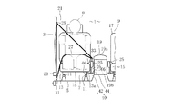
図1は本発明を適用した車両(例えば自動車)の一部を示していて、図1中1は、車室内を示している。車室内1は、ドア(図示しない)やセンタピラー3など形成される内壁
部、フロア部材5、ルーフ部材(図示しない)などで囲まれる空間で形成される。
この車室内1のフロア面には、車幅方向両側にそれぞれシート7,9が据え付けられている。ちなみにシート7,9は、いずれも例えば左右一対のシートレール11及び枠形のシートフレーム13を介してフロア部材5に組み付くシートクッション15と、同シートクッション15に組み付くシートバック17とを有して構成される。
Hereinafter, the present invention will be described based on an embodiment shown in FIGS.
FIG. 1 shows a part of a vehicle (for example, an automobile) to which the present invention is applied, and 1 in FIG. 1 shows a vehicle interior. The
On the floor surface of the
またシート7とシート9との間には、車両内装部品としてのコンソールボックス19が据え付けられている。ここでは、全高の高いコンソールボックスが据え付けられている。
各シート7,9には、それぞれシートベルト装置21が装備されている。シートベルト装置21は、例えばセンタピラー3の下段側に配置したリトラクタ23、シート7,9とコンソールボックス19との間にそれぞれ配置したバックル25とを有している。ちなみにコンソールボックス19は、車両側面視において、シート7,9やバックル25の位置よりも高く、シート7,9やバックル25と重畳(オーバラップ)している。リトラクタ23から引き出されたシートベルト27の先端部は、センタピラー3の上段に設けたベルトガイド29に通じて、センタピラー3の下段に設けたベルトアンカー31に固定されている。そして、シートベルト27の途中に組み込まれたタング33を、バックル25へ差し込み接続(係合)することにより、リトラクタ23から引き出されるシートベルト部分が、シート7(あるいはシート9)に着座した乗員αの肩部や腰部を跨るように配置され、乗員αの保持が行える(図1)。
A
Each
このようなシート7,9とコンソールボックス19との間にバックル25が配置される車両では、図4(a)に示されるように車両側部から衝撃力Fが加わる側面衝突が生じると、シート7が車幅方向内側に変位し、バックル25がコンソールボックス19と衝突して、バックル25が、シート7のシートクッション15側部(または乗員の大腿部、腰部など)とコンソールボックス19との間に挟まれ、タング33がバックル25から取り外し難くなる場合がある[図4(a)]。特にバックル25の位置よりも高いコンソールボックス19の場合、バックル25の側部に有るコンソールボックス19側面と対向する位置に設けられている解除ノブ25a(タング33の係合を解除操作する部分:図2)とコンソールボックス19の側面とは衝突しやすいため、変形や破損などより、タング33がバックル25から取り外し難くなるおそれがある。
In such a vehicle in which the
そのため、例えばシート7には、バックル取外装置40が装備されている。同装置40は、乗員αの保持を担保しつつ、バックル25がシート7(乗員α含め)とコンソールボックス19間に挟まれる状況下のとき、外部操作によりバックル25を取り外せるようにした装置である。図2には、このバックル取外装置40の外観が示され、図3には同装置40の各部の構造が示されている。
Therefore, for example, the
バックル取外装置40には、図3に示されるようなバックル25と一体に連結されたステー部材26(バックル25を支える部品)をシートフレーム13に取外し可能に支持する支持構造部42と、バックル25の取外しを行う取外機構部44とを組み合わせた構造が用いられる。
例えば図3に示されるように支持構造部42は、短軸の軸部材で構成されるバックル支持軸46(本願の支持軸に相当)を有する。このバックル支持軸46は、シートフレーム13のコンソールボックス19側の縦壁部13aの長手方向と直交または略直交する方向に挿通可能に挿通されている。そして、バックル支持軸46の先端側を縦壁部13aからコンソールボックス19(車幅方向)へ突出させている。バックル支持軸46の、一端側となる基端部(シートフレーム13側)の同一外周面には、複数の突没可能な支持軸用の係止爪48(軸係止部)が設けられている。係止爪48は、斜辺48aをバックル支持軸46の基端側に配置した三角形状の部材から構成される。これら係止爪48によりバックル支持軸46は、シート7方向へは変位するが、コンソールボックス19方向へは規制される。この係止構造により、バックル支持軸46の基端部を、シートフレーム13に挿通可能に支持している。
The
For example, as shown in FIG. 3, the
バックル支持軸46の他端側となる先端側(コンソールボックス19側)の端部には、ステー部材26の端部に設けた孔部26a(図5)が挿通可能に挿通されている。バックル支持軸46は、ステー部材26の長手方向と直交または略直交する方向に挿通可能に挿通されている。そして、このステー部材26は、バックル支持軸46のステー部材26を挟んだ両側の外周面に突没可能に設けた複数対、例えば二対の係止爪53、ここでは係止爪53a,53b(本願の係止部に相当)により規制され、ステー部材26を位置決めている。ちなみに係止爪53a,53bは、いずれもステー部材26に向く側を縦辺53e、53fとし、反対側を斜辺53c、53dとした三角形の係止爪が用いられている。むろん、バックル25は、タング33と接続しやすい位置に配置される。つまり係止爪53は、ステー部材26を対称軸として対称な係止爪であるといえ、係止爪53a及び係止爪53bの車両上下方向に延びる縦辺53e、53fによって、ステー部材26が車幅方向(支持軸46の軸方向)で挟まれている。係止爪53bの斜辺53dと係止爪48の斜辺48aは同方向に向いている。なお、係止爪53a及び係止爪53bの間には、ステー部材26の幅寸法と共に、後述する爪部54の入る分のわずかな隙間が予め設定されている。
A
支持構造部42は、こうしたバックル支持軸46および係止構造の他に、車両の側面衝突でシート7が車幅方向内側へ変位し、バックル支持軸46の先端部がコンソールボックス19に接近するに伴い、係止爪48の係合を解除する係止解除部55を有する(図3)。この係止解除部55には、後述の取外機構部44を構成する係合具66(本願の係合子に相当)を利用した機構が用いられている。
In addition to the
ここで、係合具66は、バックル支持軸46の先端側に配置された係止爪53a(53)と係脱可能な環状の係合部品から構成される。この係合具66は、例えばコンソールボックス19の外側面部分から突き出て配置されている。そして、バックル支持軸46端や係止爪53aと対向している。これにより、車両の側面衝突時、シート7がコンソールボックス19側へ変位し、バックル支持軸46の先端部がコンソールボックス19に接近すると、係合具66は、バックル支持軸46端と嵌り、係止爪53aの斜辺53cを乗り越える。そして、係合具66は、バックル支持軸46及び係止爪53aを突出したまま収納し、ステー部材26と突き当たる。
Here, the engaging
係合具66以外の係止解除部55の構造を説明すると、図3中57は、没入ガイド(本願の没入ガイド部に相当)である。没入ガイド57は、内部に通路が形成された筒形部材で構成される。この没入ガイド57は、縦壁部13a(シートフレーム13)の外側面からステー部材26に向けて突き出ていて、没入ガイド57内をバックル支持軸46が挿通している。具体的には没入ガイド57内には、縦壁部13aと、バックル支持軸46の基端側に配置された係止爪53b間のバックル支持軸部分が挿通されている。また係止爪53bとバックル支持軸46の基端部の係止爪48とは、バックル支持軸46の内部に内蔵された連動部材47(図3、図5)を介して連結され、両者が同期して突没するようになっている。これにより、係合具66がステー部材26と突き当たり、ステー部材26の動きが規制されると、それ以降の挙動、すなわち、変位し続ける縦壁部13a(シートフレーム13)によって、図5(a)のように没入ガイド57により係止爪53bが没入、さらに係止爪53bに連動して係止爪48が没入されるようにしている。つまり、バックル支持軸46がコンソールボックス19に接近すると、係止爪48の係合が解除される。これで、側面衝突を終えるまでの間、ステー部材26の支持は継続されるようにしている。と共に側面衝突後は、バックル支持軸46が、軸方向(コンソールボックス19側)へ変位可能な状態で待機する構造としている。
Explaining the structure of the unlocking
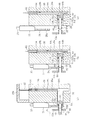
取外機構部44は、図4(a)および図5(a)のようにバックル25がシート7とコンソールボックス19との間に挟まれ、バックル25がコンソールボックス19と衝突、当接し、バックル25の解除操作が困難な状況となるとき発揮するものである(側面衝突後)。取外機構部44は、外部操作により、変位可能な状態で待機しているバックル支持軸46をステー部材26から引き出す引出し機構60(本願の引出し機構部に相当)を有して構成されている。具体的には、図3および図5のように例えば引出し機構60は、外部操作を入力する操作部、ここでは解除ボタン62がバックル25の周辺に設けられる。この解除ボタン62は、乗員αが常時は誤って操作することがないような場所、または側面衝突以外を含んだ各衝突による衝撃によって誤って操作されることがないような各衝突を考慮した場所、かつシートベルト27により拘束状態となっている乗員αから手の届く範囲に設けられることが好ましい。ここでは、例えばコンソールボックス19の一部に設けられている。すなわち、コンソールボックス19は、フロア部材5に固定される本体部19bと同本体部19bの上部開口を開閉する蓋部19aとから構成されている。このコンソールボックス19を利用して、車両上下方向に延びる解除ボタン62が設けられる。具体的には解除ボタン62は、このコンソールボックス19のうちの、例えば衝突によって誤って操作されることがないよう、蓋部19aで覆われる本体部19bの開口縁部で、コンソールボックス19の側面から車両幅方向に所定の空間を設けた位置に、復帰用の弾性部材64と共に設けられる。
As shown in FIGS. 4A and 5A, the
上記係合具66は、図4および図5のように先端部にバックル支持軸46が挿通可能な寸法を有し、かつ径方向内側に向けて環状フランジ形状の爪部54を有して形成されている。これにより係合具66は、側面衝突によりバックル支持軸46がコンソールボックス19に接近すると、バックル支持軸46の端側の係止爪53aと係合する。ここで係合具66は、本体部19bの外側面から本体部19bの壁部内に沿って車幅方向に延びるように形成された通路20の端に配置される。ちなみに通路20は、係合具66が挿通可能なものである。
As shown in FIGS. 4 and 5, the engaging
そして、図3に示されるように解除ボタン62と係合具66との間は、駆動機構部、ここでは例えば本体部19bの壁部内部の通路20や縦孔部20aに収められたリンク機構68(例えば大小複数のリンク68a,68bの組合わせ)で連結され、解除ボタン62を押すと、待機位置の係合具66が、通路20内の奥側へ向かって変位(コンソールボックス19の内側)される構造としている。ここで、リンク機構68は、解除ボタン62が押操作されると、バックル支持軸46の基端が、ステー部材26から外れるまで引っ張られるよう各部が設定されていて、押操作されると、バックル支持軸46からステー部材26(バックル25)が抜け出るようにしている。
As shown in FIG. 3, between the
こうしたバックル取外装置40により、車両の側面衝突の際は、衝突が終わるまで、乗員αの保持を継続、さらには側面衝突後、乗員αが車外へ脱出する際にバックル25の解除操作が困難(タング33の取外しができない)となるような場合、外部からの操作で、タング33が締結された状態のままバックル25(ステー部材26)が取り外せる。
この点を図4および図5を参照して詳細に説明すると、例えば図1に示されるように車両側部で衝突が発生したとする(側面衝突)。
With such a
This point will be described in detail with reference to FIGS. 4 and 5. For example, as shown in FIG. 1, it is assumed that a collision occurs on the side of the vehicle (side collision).
すると、加わる衝撃力Fにより、ドアやセンタピラー3などが車室内1aへ侵入し、シート7を押圧する。すると、シート7は、衝突側と反対側へ変位する。このシート変位を受けて、シート側方に配置されたバックル25は、ステー部材26と共に同方向へ変位する。そして、バックル25とコンソールボックス19とが衝突し、バックル25がシート7(あるいは乗員α)とコンソールボックス19との間に挟まれていく[(図4(a)]。
Then, due to the applied impact force F, the door, the
このとき、図5(a)に示されるようにバックル支持軸46の先端部は、ステー部材26を挿通した状態のまま、待機している係合具66内に差し込まれる。すると、係合具66の爪部54は、係止爪53aの斜辺53cを通り、係止爪53aをバックル支持軸46の外周面に押し込む。これにより、爪部54は、係止部53aを乗り越えて、ステー部材26と係止爪53aとの間に介在され(係止爪53と係合)、ステー部材26を規制する。
At this time, as shown in FIG. 5A, the tip of the
続くシート変位(ステー部材26の規制後)により、図5(a)に示されるように没入ガイド57は、シートフレーム13の縦壁部13aと共にバックル支持軸46上をステー部材26と接近(あるいは当接)するまで相対変位する。係止爪53bの斜辺53dは、このとき没入ガイド57によりバックル支持軸46の外周面に押し込まれ、ステー部材26の規制を解除する。また係止爪48も、支持軸46の内部に内蔵された連動部材47により係止爪53bと連動して、バックル支持軸46の外周面に押し込まれ、シートフレーム13との規制を解除する。
Due to the subsequent seat displacement (after regulation of the stay member 26), the
すると、バックル支持軸46は、ステー部材26を挿通したままで、先端側の係止爪53aの縦辺53eと係合具66の爪部54とが係合される。これによりステー部材26は、シートフレーム13と没入ガイド57に両側面が当接された状態のままで、側面衝突を終える。
側面衝突を終えても、バックル25はシート7から外れることはないので、側面衝突中から側面衝突後まで、乗員αは、シートベルト27により保持され続けられる。
Then, with the
Even after the side collision, the
このときには、例えば乗員αの脱出を助ける人の手を借り、図4(b)および図5(b)に示されるようにコンソールボックス19の蓋部19aを開き、露出する解除ボタン62を押操作する。これにより、押操作力は、リンク機構68を介して、係合具66へ伝わり、係合具66がコンソールボックス19の壁部内へ通路20沿い引き込まれる。つまり、係止具66は、係合具66の爪部54と係止爪53aの縦辺53eとが係合したまま、引っ張られることとなる。
At this time, for example, with the help of a person who helps escape of the occupant α, as shown in FIGS. 4B and 5B, the
このとき、バックル支持軸46は、係止爪48及び係止爪53bの係止が解かれており、前進(コンソールボックス19方向)可能な状態で待機している。ここで、係止爪48及び係止爪53bは、連続する没入ガイド57、ステー部材26の孔部26aを通過するまでの間、押し込まれた状態が保ち続けられるから、バックル支持軸46は、図5(a)から図5(b)の状態へと、係止爪48、係止爪53bがバックル支持軸46の外周面に押し込まれた状態のまま、通路20内へ引き込まれる。これで、係止爪48、係止爪53bは、ステー部材26を通過する。
At this time, the
バックル支持軸46の基端部が、図5(b)および図5(c)に示されるようにシートフレーム13からステー部材26の孔部26aを通過するまで引き出されると、図4(b)に示されるようにステー部材26は、バックル支持軸46から抜け出る。ちなみに、係止爪48,53bは、ステー部材26の孔部26aを通過した後、外方へ突き出て、コンソールボックス19の通路20内に収容されるが、ステー部材26の抜けには影響を与えない。
When the base end portion of the
これにより、バックル25は、シート7から外れる。つまり、乗員αは、シートベルト27による保持から開放される。
それ故、バックル取外装置40の採用により、シートベルト27による乗員αの保持が確保されるだけでなく、側面衝突後、バックル25が、シート7とコンソールボックス19間に挟まれたとしても、容易にバックル25をシート7から外すことができる。
As a result, the
Therefore, the adoption of the
しかも、ステー部材25の係止には。突没可能な係止爪53を用いたり、同係止爪53の係止解除には、没入ガイド57を用いたので、支持構造部42は、簡単な構造ですむ。
そのうえ、引出し機構60(引出し機構部)も、解除ボタン62(操作部)の操作により、リンク機構68(駆動機構部)で、係合具66を用い、バックル支持軸46をコンソールボックス19側へ引き出す機構を用いたので、簡単な構造ですむ。
Moreover, the
In addition, the drawer mechanism 60 (drawer mechanism section) is also operated by the release button 62 (operation section), and the link mechanism 68 (drive mechanism section) uses the
もちろん、バックル25の取外しは、乗員自体が操作することも可能であり、乗員以外、例えば救助者が操作することも可能である。
なお、上述した実施形態における各構成およびそれの組合わせ等は一例であり、本発明の趣旨から逸脱しない範囲内で、構成の付加、省略、置換、およびその他の変更が可能であることはいうまでもない。また本発明は、実施形態によって限定されることはなく、「特許請求の範囲」によってのみ限定されることはいうまでもない。例えば一実施形態では、係止爪、没入ガイド、リンク機構、コンソールボックスなどを用いたが、他の部品や他の電気的なアクチュエータを用いても構わない。また一実施形態では、バックル支持軸の先端側部のステー部材を係止する係止爪を被係止部として用いて、係合具と係合させる構造を挙げたが、これに限らず、別途、バックル支持軸に被係止部を設ける構造でもよい。
Of course, the detachment of the
Note that each configuration in the above-described embodiment, a combination thereof, and the like are examples, and it is possible to add, omit, replace, and otherwise change the configuration without departing from the spirit of the present invention. Not too long. Further, the present invention is not limited by the embodiment, and it is needless to say that the present invention is limited only by the “claims”. For example, in one embodiment, a locking claw, an immersion guide, a link mechanism, a console box, and the like are used, but other parts and other electrical actuators may be used. Moreover, in one embodiment, although the structure which engages with an engaging tool using the latching claw which latches the stay member of the front end side part of a buckle support shaft as a to-be-latched part was mentioned, Separately, a structure in which a locked portion is provided on the buckle support shaft may be employed.
1 車室内
7 シート
19 コンソールボックス(車両内装部品)
25 バックル
26 ステー部材
40 バックル取外装置
42 支持構造部
44 取外機構部
46 バックル支持軸(支持軸)
53 係止爪(係止部)
55 係止解除部
57 没入ガイド(没入ガイド部、係止解除部)
60 引出し機構(引出し機構部)
62 解除ボタン(操作部)
66 係合具(係合子)
68 リンク機構(駆動機構部)
1
25
53 Locking claw (locking part)
55
60 Drawer mechanism (drawer mechanism part)
62 Release button (operation unit)
66 Engagement tool (engagement element)
68 Link mechanism (drive mechanism)
Claims (3)
前記シートと車幅方向に並んで配置された車両内装部品と、
前記シートと前記車両内装部品との間に配置されるシートベルトのバックルおよび同バックルと一体なステー部材と、
前記ステー部材を前記シートのシートフレームに取外し可能に支持する支持構造部と、
前記バックルを取外す取外機構部と、
を備え、
前記支持構造部は、
一端側が前記シートフレームに挿通可能に支持され、他端側が前記ステー部材に挿通可能に挿通される支持軸と、
前記ステー部材を前記支持軸に係止する係止部と、
側面衝突時におけるシート変位により、前記バックルが前記車両内装部品に接近するのに伴い、前記係止部の係止を解除する係止解除部と、
を有し、
前記取外機構部は、
前記バックルと前記車両内装部品が衝突した際に、外部操作により、前記支持軸を前記車両内装部品側へ引き出す引出し機構部を有する、
ことを特徴とするバックル取外装置。 A seat provided in the passenger compartment;
Vehicle interior parts arranged side by side in the vehicle width direction with the seat;
A seat belt buckle disposed between the seat and the vehicle interior part, and a stay member integral with the buckle;
A support structure that removably supports the stay member on a seat frame of the seat;
A removal mechanism for removing the buckle;
With
The support structure is
One end side is supported so as to be able to be inserted into the seat frame, and the other end side is supported so as to be able to be inserted into the stay member;
A locking portion for locking the stay member to the support shaft;
An unlocking portion for releasing the locking of the locking portion as the buckle approaches the vehicle interior part due to a seat displacement at the time of a side collision,
Have
The removal mechanism is
When the buckle and the vehicle interior part collide, it has a drawer mechanism part that pulls the support shaft to the vehicle interior part side by an external operation.
A buckle removing device characterized by that.
前記係止解除部は、前記係止爪を没入させる没入ガイド部を有する、
ことを特徴とする請求項1に記載のバックル取外装置。 The locking portion has a locking claw provided on the outer peripheral surface of the support shaft so as to protrude and retract,
The locking release part has an immersion guide part for immersing the locking claw.
The buckle removing device according to claim 1, wherein
操作部と、
前記車両内装部品に設けられ、前記車両内装部品へ接近する前記支持軸に対して係合する係合子と、
前記操作部からの操作により、前記係合子を車両内装部品方向へ変位させる駆動機構部と、
を有することを特徴とする請求項1または請求項2に記載のバックル取外装置。 The drawer mechanism is
An operation unit;
An engagement member provided on the vehicle interior part and engaged with the support shaft approaching the vehicle interior part;
A drive mechanism for displacing the engagement element toward a vehicle interior part by an operation from the operation unit;
The buckle removing device according to claim 1, wherein the buckle removing device is provided.
Priority Applications (1)
| Application Number | Priority Date | Filing Date | Title |
|---|---|---|---|
| JP2014068854A JP6233593B2 (en) | 2014-03-28 | 2014-03-28 | Buckle removal device |
Applications Claiming Priority (1)
| Application Number | Priority Date | Filing Date | Title |
|---|---|---|---|
| JP2014068854A JP6233593B2 (en) | 2014-03-28 | 2014-03-28 | Buckle removal device |
Publications (2)
| Publication Number | Publication Date |
|---|---|
| JP2015189368A JP2015189368A (en) | 2015-11-02 |
| JP6233593B2 true JP6233593B2 (en) | 2017-11-22 |
Family
ID=54424250
Family Applications (1)
| Application Number | Title | Priority Date | Filing Date |
|---|---|---|---|
| JP2014068854A Expired - Fee Related JP6233593B2 (en) | 2014-03-28 | 2014-03-28 | Buckle removal device |
Country Status (1)
| Country | Link |
|---|---|
| JP (1) | JP6233593B2 (en) |
Family Cites Families (3)
| Publication number | Priority date | Publication date | Assignee | Title |
|---|---|---|---|---|
| KR0181247B1 (en) * | 1996-10-26 | 1999-05-01 | 현대자동차주식회사 | 2 point type safety belt buckle operating assembly |
| EP1698521A1 (en) * | 2005-03-04 | 2006-09-06 | Mazda Motor Corporation | Occupant protection device and method for a vehicle |
| JP2011225151A (en) * | 2010-04-21 | 2011-11-10 | Mitsubishi Motors Corp | Seat belt buckle device |
-
2014
- 2014-03-28 JP JP2014068854A patent/JP6233593B2/en not_active Expired - Fee Related
Also Published As
| Publication number | Publication date |
|---|---|
| JP2015189368A (en) | 2015-11-02 |
Similar Documents
| Publication | Publication Date | Title |
|---|---|---|
| JP2005255100A (en) | Headrest for automobile | |
| JP5643282B2 (en) | Child seats and shoulder pads for vehicles | |
| JP2014104943A (en) | Child car seat | |
| JP4890363B2 (en) | Seat belt buckle device | |
| JP2020011718A (en) | Webbing height adjustment device | |
| JP2008024110A (en) | Seat slide device for automobile | |
| JP4580337B2 (en) | Headrest bush and vehicle seat using the same | |
| JP6233593B2 (en) | Buckle removal device | |
| US9277788B2 (en) | Dual release buckle assemblies and associated systems and methods | |
| JP5045944B2 (en) | Vehicle seat belt device | |
| JP6233592B2 (en) | Buckle removal device | |
| JP6292386B2 (en) | Vehicle occupant protection device | |
| JP6176715B2 (en) | Buckle and seat belt device provided with the same | |
| JP6040461B2 (en) | Seat belt holding bezel, seat belt guide unit and seat belt device | |
| JP6487757B2 (en) | Shoulder adjuster for seat belt | |
| JP7130235B2 (en) | Seatbelt erroneous operation prevention tool | |
| JP2011079370A (en) | Lock unit mounting structure of seat slide lock device for vehicle | |
| JP5653741B2 (en) | Buckle and seat belt device provided with the same | |
| JP2010116060A (en) | Driver's seat air bag device mounting structure and steering wheel | |
| JP2007308062A (en) | Seat belt device for vehicle | |
| KR100820439B1 (en) | Folding Structure for Rear Seat Cushion | |
| JP2012183908A (en) | Seat belt system | |
| JP2012224253A (en) | Tongue plate fixing structure for vehicle seat belt | |
| JP6240577B2 (en) | Seat belt device | |
| GB2492814A (en) | Seatbelt assembly |
Legal Events
| Date | Code | Title | Description |
|---|---|---|---|
| A621 | Written request for application examination |
Free format text: JAPANESE INTERMEDIATE CODE: A621 Effective date: 20161222 |
|
| TRDD | Decision of grant or rejection written | ||
| A01 | Written decision to grant a patent or to grant a registration (utility model) |
Free format text: JAPANESE INTERMEDIATE CODE: A01 Effective date: 20170927 |
|
| A977 | Report on retrieval |
Free format text: JAPANESE INTERMEDIATE CODE: A971007 Effective date: 20170928 |
|
| A61 | First payment of annual fees (during grant procedure) |
Free format text: JAPANESE INTERMEDIATE CODE: A61 Effective date: 20171010 |
|
| R151 | Written notification of patent or utility model registration |
Ref document number: 6233593 Country of ref document: JP Free format text: JAPANESE INTERMEDIATE CODE: R151 |
|
| S531 | Written request for registration of change of domicile |
Free format text: JAPANESE INTERMEDIATE CODE: R313531 |
|
| R350 | Written notification of registration of transfer |
Free format text: JAPANESE INTERMEDIATE CODE: R350 |
|
| LAPS | Cancellation because of no payment of annual fees |