JP6233338B2 - Information terminal, system, information processing method, and program - Google Patents
Information terminal, system, information processing method, and program Download PDFInfo
- Publication number
- JP6233338B2 JP6233338B2 JP2015055965A JP2015055965A JP6233338B2 JP 6233338 B2 JP6233338 B2 JP 6233338B2 JP 2015055965 A JP2015055965 A JP 2015055965A JP 2015055965 A JP2015055965 A JP 2015055965A JP 6233338 B2 JP6233338 B2 JP 6233338B2
- Authority
- JP
- Japan
- Prior art keywords
- information
- input
- image processing
- output
- unit
- Prior art date
- Legal status (The legal status is an assumption and is not a legal conclusion. Google has not performed a legal analysis and makes no representation as to the accuracy of the status listed.)
- Active
Links
Images


Classifications
-
- G—PHYSICS
- G06—COMPUTING; CALCULATING OR COUNTING
- G06F—ELECTRIC DIGITAL DATA PROCESSING
- G06F3/00—Input arrangements for transferring data to be processed into a form capable of being handled by the computer; Output arrangements for transferring data from processing unit to output unit, e.g. interface arrangements
- G06F3/12—Digital output to print unit, e.g. line printer, chain printer
- G06F3/1201—Dedicated interfaces to print systems
- G06F3/1202—Dedicated interfaces to print systems specifically adapted to achieve a particular effect
- G06F3/1222—Increasing security of the print job
-
- G—PHYSICS
- G06—COMPUTING; CALCULATING OR COUNTING
- G06F—ELECTRIC DIGITAL DATA PROCESSING
- G06F3/00—Input arrangements for transferring data to be processed into a form capable of being handled by the computer; Output arrangements for transferring data from processing unit to output unit, e.g. interface arrangements
- G06F3/12—Digital output to print unit, e.g. line printer, chain printer
- G06F3/1201—Dedicated interfaces to print systems
- G06F3/1202—Dedicated interfaces to print systems specifically adapted to achieve a particular effect
- G06F3/1203—Improving or facilitating administration, e.g. print management
- G06F3/1204—Improving or facilitating administration, e.g. print management resulting in reduced user or operator actions, e.g. presetting, automatic actions, using hardware token storing data
-
- G—PHYSICS
- G06—COMPUTING; CALCULATING OR COUNTING
- G06F—ELECTRIC DIGITAL DATA PROCESSING
- G06F3/00—Input arrangements for transferring data to be processed into a form capable of being handled by the computer; Output arrangements for transferring data from processing unit to output unit, e.g. interface arrangements
- G06F3/12—Digital output to print unit, e.g. line printer, chain printer
- G06F3/1201—Dedicated interfaces to print systems
- G06F3/1223—Dedicated interfaces to print systems specifically adapted to use a particular technique
- G06F3/1237—Print job management
- G06F3/1238—Secure printing, e.g. user identification, user rights for device usage, unallowed content, blanking portions or fields of a page, releasing held jobs
-
- G—PHYSICS
- G06—COMPUTING; CALCULATING OR COUNTING
- G06F—ELECTRIC DIGITAL DATA PROCESSING
- G06F3/00—Input arrangements for transferring data to be processed into a form capable of being handled by the computer; Output arrangements for transferring data from processing unit to output unit, e.g. interface arrangements
- G06F3/12—Digital output to print unit, e.g. line printer, chain printer
- G06F3/1201—Dedicated interfaces to print systems
- G06F3/1278—Dedicated interfaces to print systems specifically adapted to adopt a particular infrastructure
- G06F3/1285—Remote printer device, e.g. being remote from client or server
- G06F3/1288—Remote printer device, e.g. being remote from client or server in client-server-printer device configuration
-
- G—PHYSICS
- G06—COMPUTING; CALCULATING OR COUNTING
- G06F—ELECTRIC DIGITAL DATA PROCESSING
- G06F3/00—Input arrangements for transferring data to be processed into a form capable of being handled by the computer; Output arrangements for transferring data from processing unit to output unit, e.g. interface arrangements
- G06F3/12—Digital output to print unit, e.g. line printer, chain printer
- G06F3/1201—Dedicated interfaces to print systems
- G06F3/1278—Dedicated interfaces to print systems specifically adapted to adopt a particular infrastructure
- G06F3/1292—Mobile client, e.g. wireless printing
-
- G—PHYSICS
- G06—COMPUTING; CALCULATING OR COUNTING
- G06F—ELECTRIC DIGITAL DATA PROCESSING
- G06F3/00—Input arrangements for transferring data to be processed into a form capable of being handled by the computer; Output arrangements for transferring data from processing unit to output unit, e.g. interface arrangements
- G06F3/12—Digital output to print unit, e.g. line printer, chain printer
- G06F3/1201—Dedicated interfaces to print systems
- G06F3/1223—Dedicated interfaces to print systems specifically adapted to use a particular technique
- G06F3/1275—Print workflow management, e.g. defining or changing a workflow, cross publishing
Landscapes
- Engineering & Computer Science (AREA)
- Theoretical Computer Science (AREA)
- Human Computer Interaction (AREA)
- Physics & Mathematics (AREA)
- General Engineering & Computer Science (AREA)
- General Physics & Mathematics (AREA)
- Computer Security & Cryptography (AREA)
- Computer Networks & Wireless Communication (AREA)
- Facsimiles In General (AREA)
Description
本発明は、情報端末、システム、情報処理方法、及びプログラムに関する。
The present invention relates to an information terminal, a system, an information processing method, and a program.
例えば、印刷、コピー、スキャン、ファクシミリ送信等の複数の機能を有するMFP(Multifunction Peripheral/Product)等の画像形成装置が知られている。また、画像形成装置が提供するAPI(Application Programming Interface)を用いて、スマートフォンや、タブレット端末等のスマートデバイスから画像形成装置の画像形成機能を利用する技術が知られている。 For example, an image forming apparatus such as an MFP (Multifunction Peripheral / Product) having a plurality of functions such as printing, copying, scanning, and facsimile transmission is known. Also, a technique for using an image forming function of an image forming apparatus from a smart device such as a smartphone or a tablet terminal using an API (Application Programming Interface) provided by the image forming apparatus is known.
また、端末からの出力要求より抽出したユーザ固有情報に基づいて出力先の画像形成装置を決定し、決定した出力先に対して出力要求に係る描画データを出力する出力振り分け装置が知られている(例えば、特許文献1参照)。 There is also known an output distribution device that determines an output destination image forming apparatus based on user-specific information extracted from an output request from a terminal and outputs drawing data related to the output request to the determined output destination. (For example, refer to Patent Document 1).
従来の技術は、情報端末から、例えば、MFP等の画像形成装置の機能を利用するためのものであり、情報端末は、処理対象となる印刷データや、スキャンデータ等にアクセス可能であった。そのため、例えば、個人のスマートデバイスを社内ネットワーク等に接続して利用するBYOD(Bring Your Own Device)等の環境では、処理対象となるデータが、個人のスマートデバイスに格納されること等による情報流出のリスクがあった。 The prior art is for using functions of an image forming apparatus such as an MFP from an information terminal, and the information terminal can access print data, scan data, and the like to be processed. For this reason, for example, in an environment such as BYOD (Bring Your Own Device) in which a personal smart device is connected to an in-house network or the like, information leaks due to the data to be processed being stored in the personal smart device. There was a risk.
また、情報端末から、例えば、電子黒板に書き込まれた画像情報をMFPに印刷させる等、複数の画像処理装置による画像処理を制御する場合、情報端末に処理対象となるデータを格納することなく、処理を制御することは困難であった。 Further, when controlling image processing by a plurality of image processing devices such as causing an MFP to print image information written on an electronic blackboard from an information terminal, for example, without storing data to be processed in the information terminal, It was difficult to control the process.
このように、従来の技術では、スマートデバイス等の情報端末を用いて、処理対象となるデータの情報流出を抑制しつつ、複数の画像処理装置による画像処理を制御することには困難を伴っていた。 As described above, in the conventional technique, it is difficult to control image processing by a plurality of image processing apparatuses while suppressing information leakage of data to be processed using an information terminal such as a smart device. It was.
本発明の実施の形態は、上記問題点に鑑みてなされたものであって、スマートデバイス等の情報端末を用いて、処理対象となるデータの情報流出を抑制しつつ、複数の画像処理装置による画像処理の制御を容易にすることを目的とする。 Embodiments of the present invention have been made in view of the above-described problems. By using an information terminal such as a smart device, an information outflow of data to be processed is suppressed, and a plurality of image processing apparatuses are used. and an object that you to facilitate control of the image processing.
上記課題を解決するため、本発明の一実施形態に係る情報端末は、入力処理を実行する入力機器と、前記入力処理に応じた出力処理を実行する出力機器による画像処理の実行を制御する情報処理装置とネットワークを介して接続する情報端末であって、前記入力機器及び前記出力機器として利用可能な機器を含む複数の機器を示す画面を表示する表示手段と、前記入力機器を、前記複数の機器から前記画面に対する第1の機器選択操作に基づいて特定し、前記出力機器を、前記複数の機器から前記第1の機器選択操作後の前記画面に対する第2の機器選択操作に基づいて特定する特定手段と、前記第1の機器選択操作によって特定された第1の機器を識別する情報を前記入力機器として指定し、前記第2の機器選択操作によって特定された第2の機器を識別する情報を前記出力機器として指定する指定情報を前記情報処理装置に送信する送信手段と、を有する。 In order to solve the above-described problem, an information terminal according to an embodiment of the present invention includes an input device that executes input processing and information that controls execution of image processing by an output device that executes output processing according to the input processing. An information terminal connected to a processing device via a network, wherein the display unit displays a screen showing a plurality of devices including devices that can be used as the input device and the output device, and the input device includes the plurality of input devices. The device is specified based on a first device selection operation on the screen, and the output device is specified from the plurality of devices based on a second device selection operation on the screen after the first device selection operation. specifying means, second specifying information identifying a first device that is identified by the first device selection operation as the input device, identified by the second device selection operation Designation information designating the information identifying the device as the output device and a transmission means for transmitting to the information processing apparatus.
本発明の実施の形態によれば、スマートデバイス等の情報端末を用いて、処理対象となるデータの情報流出を抑制しつつ、複数の画像処理装置による画像処理の制御を容易にすることができる。 According to the embodiment of the present invention, by using an information terminal such as a smart device, while suppressing information leakage of data to be processed, and this to facilitate control of the image processing by the plurality of image processing apparatuses it can.
以下に、本発明の実施の形態について、添付の図面を参照して説明する。 Embodiments of the present invention will be described below with reference to the accompanying drawings.
<システムの構成>
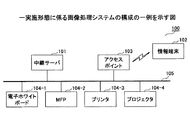
図1は一実施形態に係る画像処理システムの構成の一例を示す図である。画像処理システム100は、例えば、インターネットや、LAN等のネットワーク105に接続された中継サーバ101、アクセスポイント103、電子ホワイトボード104−1、MFP(Multifunction Peripheral/Product)104−2、プリンタ104−3、プロジェクタ104−4等を有する。また、画像処理システム100は、アクセスポイント103を介してネットワーク105に接続可能な情報端末102を有する。
<System configuration>
FIG. 1 is a diagram illustrating an example of a configuration of an image processing system according to an embodiment. The
尚、電子ホワイトボード104−1、MFP104−2、プリンタ104−3、及びプロジェクタ104−4は、画像処理システム100に含まれる1つ以上の画像処理装置の一例である。1つ以上の画像処理装置は、例えば、スキャナ、カメラ、ディスプレイ、サイネージ、テレビ、テレビ会議装置等の他の画像処理装置を含んでいても良い。尚、以後の説明の中で、1つ以上の画像処理装置のうち、任意の画像処理装置を示す場合、「画像処理装置104」を用いる。
The electronic whiteboard 104-1, the MFP 104-2, the printer 104-3, and the projector 104-4 are examples of one or more image processing apparatuses included in the
中継サーバ101は、情報端末102からの指示に応じて、1つ以上の画像処理装置104からの画像データの入力や、出力等の制御を行う情報処理装置である。中継サーバ101は、情報端末102から指示された、入力用の画像処理装置104(例えば、MFP104−2)から画像データを取得し、出力用の画像処理装置104(例えば、電子ホワイトボード104−1)に出力する等の制御等を行う。
The
情報端末102は、例えば、スマートフォン、タブレット端末、PC(Personal Computer)等の情報処理装置であり、中継サーバ101に対して、上記のような1つ以上の画像処理装置104による画像データの入力や、出力等の指示を行う。
The
アクセスポイント103は、情報端末102等の無線LAN機器をネットワーク105に接続するための接続装置である。アクセスポイント103は、ネットワーク105への接続を要求する無線LAN機器の認証を行い、認証が許可された無線LAN機器のネットワーク105への接続を許可する。アクセスポイント103により認証が許可された無線LAN機器は、ネットワーク105に接続された中継サーバ101や、1つ以上の画像処理装置104等のネットワーク機器とのデータ通信が可能となる。
The
電子ホワイトボード104−1は、例えば、液晶ディスプレイ等のフラットパネルディスプレイや、プロジェクタの投影スクリーン等にタッチパネルを搭載し、資料等を表示しながら、手書きによる描画データを入力することができる画像処理装置である。 The electronic whiteboard 104-1 includes, for example, a flat panel display such as a liquid crystal display, a projection screen of a projector, and the like, and an image processing apparatus capable of inputting handwritten drawing data while displaying materials and the like. It is.
MFP104−2は、例えば、印刷、コピー、スキャン、ファクシミリ等の複数の画像形成機能を有する画像処理装置である。プリンタ104−3は、画像の印刷機能を有する画像処理装置である。プロジェクタ104−4は、画像の投影機能を有する画像処理装置である。 The MFP 104-2 is an image processing apparatus having a plurality of image forming functions such as printing, copying, scanning, and facsimile. The printer 104-3 is an image processing apparatus having an image printing function. The projector 104-4 is an image processing apparatus having an image projection function.
上記構成により、利用者は、情報端末102を用いて、入力用の画像処理装置104と出力用の画像処理装置104とを指定する指定情報を、中継サーバ101に送信する。また、情報端末102から指定情報を受信した中継サーバ101は、指定情報に基づいて、入力用の画像処理装置104から入力データを取得し、取得した入力データに基づく出力データを出力用の画像処理装置104に送信する。このとき、情報端末102は、画像処理の対象となるデータを、情報端末102に取得することなく、複数の画像処理装置104による画像処理を制御することができる。
With the above configuration, the user uses the
このように、本実施形態によれば、スマートデバイス等の情報端末102を用いて、処理対象となるデータの情報流出を抑制しつつ、複数の画像処理装置104による画像処理の制御を容易にする画像処理システム100を提供することができる。
As described above, according to this embodiment, the
尚、図1のシステム構成は一例であり、本実施形態に係る画像処理システム100は、様々なシステム構成が可能である。
The system configuration in FIG. 1 is an example, and the
図2は、一実施形態に係る画像処理システム100のシステム構成の別の一例を示す図である。図2の例では、電子ホワイトボード104−1、MFP104−2、プリンタ104−3、及びプロジェクタ104−4は、アクセスポイント103を介してネットワーク105に接続されている。このように、1つ以上の画像処理装置104は、無線LAN等の無線通信によって、ネットワーク105に接続されているものであっても良い。
FIG. 2 is a diagram illustrating another example of the system configuration of the
さらに、画像処理システム100は、有線LAN接続された画像処理装置104と、無線LAN接続された画像処理装置104とが混在しているもの等であっても良い。
Further, the
<ハードウェア構成>
(中継サーバのハードウェア構成)
図3は、一実施形態に係る中継サーバのハードウェア構成例を示す図である。中継サーバ101は、一般的なコンピュータの構成を有しており、例えば、CPU(Central Processing Unit)301、RAM(Random Access Memory)302、ROM(Read Only Memory)303、ストレージ部304、ネットワークI/F(Interface)部305、外部I/F部306、表示部307、入力部308、及びバス309等を含む。
<Hardware configuration>
(Hardware configuration of relay server)
FIG. 3 is a diagram illustrating a hardware configuration example of the relay server according to the embodiment. The
CPU301は、ROM303やストレージ部304等に格納されたプログラムやデータ等をRAM302上に読み出し、処理を実行することで、中継サーバ101の各機能を実現する演算装置である。RAM302は、CPU301のワークエリア等として用いられる揮発性のメモリである。ROM303は、電源を切ってもプログラムやデータを保持する不揮発性のメモリであり、例えば、フラッシュROM等により構成される。ストレージ部304は、例えば、HDD(Hard Disk Drive)や、SSD(Solid State Drive)等のストレージ装置であり、例えば、OS(Operation System)、アプリケーションプログラム(以下、アプリと呼ぶ)、及び各種データ等を記憶する。
The
ネットワークI/F部305は、中継サーバ101をネットワーク105に接続し、情報端末102や、画像処理装置104等とデータの送受信を行うための、例えば、有線/無線LAN等の通信インタフェースである。
A network I /
外部I/F部306は、中継サーバ101に外部装置を接続するためのインタフェースである。外部装置には、例えば、USBメモリ、メモリカード、光学ディスク等の記録媒体や、各種の電子機器等が含まれる。
The external I /
表示部307は、中継サーバ101の処理結果等を表示する、例えば、LCD(Liquid Crystal Display)等のディスプレイ装置である。入力部308は、中継サーバ101の操作を行うための入力を受付ける、例えば、キーボード、マウス、タッチパネル等の入力装置である。尚、表示部307又は入力部308は、中継サーバ101の外部に設けられていても良い。バス309は、上記の各構成要素に共通に接続され、アドレス信号、データ信号、及び各種制御信号等を伝達する。
The
(情報端末のハードウェア構成)
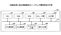
図4は、一実施形態に係る情報端末のハードウェア構成例を示す図である。情報端末102は、一般的なコンピュータの構成を有しており、例えば、CPU401、RAM402、ROM403、ストレージ部404、カメラ部405、NFC(Near Field Communication)通信部406、Bluetooth(登録商標) Low Energy(以下、BLEと呼ぶ)通信部407、ネットワークI/F部408、表示入力部409、及びバス410等を含む。
(Information terminal hardware configuration)
FIG. 4 is a diagram illustrating a hardware configuration example of the information terminal according to the embodiment. The
尚、CPU401、RAM402、ROM403、ストレージ部404、バス410等の構成は、図3の中継サーバ101の構成と同様なので、ここでは差分を中心に説明を行う。
Note that the configuration of the
カメラ部405は、画像を撮像するための撮像装置であり、例えば、画像処理装置104のQRコード(登録商標)等の2次元コード等を撮像して、画像処理装置104の宛先情報や、機器情報等を取得する場合等に用いられる。
The
NFC通信部406は、例えば、画像処理装置104のNFCリーダ/ライタ等と所定の距離(例えば、10cm以内)に近接させることにより、NFCリーダ/ライタとNFC通信を行う通信装置である。NFC通信部406は、例えば、画像処理装置104のNFCリーダ/ライタから、画像処理装置104の宛先情報や、機器情報等を取得する場合等に用いられる。
The
BLE通信部407は、例えば、画像処理装置104とBLE通信を行うための通信装置である。BLEは、近距離無線通信技術であるBluetoothの拡張仕様の1つであり、Bluetooth 4.0規格の一部として策定された近距離無線通信技術である。BLEにより、通常のBluetooth通信よりも低消費電力で近距離無線通信によるデータ通信を実現することができる。
The
尚、NFC通信部406、及びBLE通信部407は、情報端末102が有する近距離無線通信手段の一例である。情報端末102は、NFC通信部406や、BLE通信部407に代えて、他の近距離無線通信手段により、画像処理装置104と通信を行うものであっても良い。
Note that the
ネットワークI/F部408は、情報端末102をネットワーク105に接続し、中継サーバ101等とデータの送受信を行うための、例えば、無線LAN等の通信インタフェースである。
The network I /
表示入力部409は、例えば、タッチパネルとディスプレイが一体化されたタッチパネルディスプレイ等の表示入力装置であり、情報端末102の操作を行うための入力部と、情報端末102の処理結果等を表示する表示部とを含む。尚、表示入力部409は、表示部と入力部とが別々に設けられているものであっても良い。
The
(画像処理装置のハードウェア構成)
図5は、一実施形態に係る画像処理装置のハードウェア構成例を示す図である。尚、ここでは、画像処理装置104の一例として、MFPのハードウェア構成例を説明する。
(Hardware configuration of image processing device)
FIG. 5 is a diagram illustrating a hardware configuration example of the image processing apparatus according to the embodiment. Here, as an example of the
画像処理装置(MFP)104は、コントローラ501、画像読取部502、プロッタ部503、画像処理・エンジン制御部504、FAX部505、ストレージ部506、操作部507、NFC R/W(Reader/Writer)部508等を有する。
The image processing apparatus (MFP) 104 includes a
コントローラ501は、一般的なコンピュータの構成を有しており、例えば、CPU509、RAM510、ROM511、外部I/F部512、操作I/F部513、NFC I/F部514、BLE通信部515、ネットワークI/F部516等が、バス517を介して接続されている。
The
CPU509は、ROM511やストレージ部506等に格納されたプログラムやデータをRAM510上に読み出し、処理を実行することにより、画像処理装置104の各機能を実現する演算装置である。RAM510は、CPU509のワークエリア等として用いられる揮発性のメモリである。ROM511は、電源を切ってもプログラムやデータを保持する不揮発性のメモリであり、例えば、フラッシュROM等により構成される。
The
外部I/F部512は、外部装置とのインタフェースである。外部装置には、例えば、USBメモリ、メモリカード、光学ディスク等の記録媒体や、各種の電子機器等が含まれる。操作I/F部513は、操作部507をコントローラ501に接続するためのインタフェースである。NFC I/F部514は、NFC通信により、NFC機器に対するデータの読み込み、書き込み等を行うNFC R/W部508をコントローラ501に接続するためのインタフェースである。
The external I /
BLE通信部515は、BLEによる近距離無線通信を行うための無線通信部である。ネットワークI/F部516は、画像処理装置104をネットワーク105に接続し、ネットワークに接続された中継サーバ101等とデータの送受信を行うための通信インタフェースである。バス517は、上記の各構成要素に共通に接続され、例えば、アドレス信号、データ信号、及び各種制御信号等を伝達する。
The
画像読取部502は、画像処理・エンジン制御部504の制御に従って、原稿等の画像を読取るスキャナエンジン等である。プロッタ部503は、画像処理・エンジン制御部504の制御に従って、紙等に画像を出力するプリンタエンジン等である。画像処理・エンジン制御部504は、画像読取部502や、プロッタ部503を制御して、画像処理を実行する。
The
FAX部505は、ファックスの送受信を行うハードウェアエンジンと、その制御部等を含む。ストレージ部506は、例えば、HDDや、SSD等のストレージ装置であり、例えば、OS、アプリ、画像データ等を含む各種の情報及びデータを記憶する。
The
操作部507は、利用者からの入力操作を受付けるための入力部であると共に、ユーザに向けた表示を行う表示部である。尚、図4の例では、操作部507は、NFC通信により、NFC機器に対するデータの読み込み、書き込み等を行うNFC R/W部508を備えている。尚、図5の構成はあくまで一例であって、NFC R/W部508は、操作部とは別に設けられているものであっても良い。
The
本実施形態に係る画像処理装置104は、例えば、図5に示すMFPのように、コンピュータの構成と、各画像処理装置104の画像処理機能を実現するための画像処理エンジン等を含む。
The
[第1の実施形態]
<機能構成>
図6は、第1の実施形態に係る画像処理システムの機能構成図である。画像処理システム100は、中継サーバ101、情報端末102、及び1つ以上の画像処理装置104の例として、電子ホワイトボード104−1、MFP104−2、プリンタ104−3、プロジェクタ104−4等を含む。また、アクセスポイント103は、本実施形態の機能構成に影響しないため、記載を省略している。
[First Embodiment]
<Functional configuration>
FIG. 6 is a functional configuration diagram of the image processing system according to the first embodiment. The
(中継サーバの機能構成)
中継サーバ101は、通信手段601、指定情報受信手段602、データ形式決定手段603、入力データ取得手段604、変換手段605、出力データ送信手段606、記憶手段607等を含む。
(Functional configuration of relay server)
The
通信手段601は、中継サーバ101をネットワーク105に接続し、情報端末102や、1つ以上の画像処理装置104等とのデータ通信を実現するための手段である。通信手段601は、例えば、図3のネットワークI/F部305等によって実現される。
The
指定情報受信手段602は、1つ以上の画像処理装置104のうち、入力用の画像処理装置と出力用の画像処理装置とを指定する指定情報を、情報端末102等から受信する。好ましくは、指定情報受信手段602は、受信した指定情報を、例えば、記憶手段607に指定情報608として記憶する。
The designation
データ形式決定手段603は、指定情報608に含まれる、入力用の画像処理装置で利用可能なデータ形式の情報と、出力用の画像処理装置で利用可能なデータ形式の情報とに基づいて、入力用の画像処置装置から取得する入力データのデータ形式を決定する。尚、具体的な決定処理については後述する。
The data
入力データ取得手段604は、指定情報受信手段602が情報端末102等から受信した指定情報に基づいて、入力用の画像処理装置から入力データを取得する。例えば、入力データ取得手段604は、指定情報で指定された入力用の画像処理装置から、データ形式決定手段603によって決定されたデータ形式で入力データを取得する。好ましくは、入力データ取得手段604は、取得した入力データを、例えば、記憶手段607にコンテンツデータ609として記憶する。
The input
変換手段605は、入力データ取得手段604が取得したコンテンツデータ(入力データ)609を、指定情報608に含まれる出力用の画像処理装置で利用可能なデータ形式に関する情報に基づいて、出力用の画像処理装置で利用可能なデータ形式に変換する。尚、変換手段605は、入力データ取得手段604が取得したコンテンツデータ609を、出力用の画像処理装置がそのまま利用可能な場合、コンテンツデータ609のデータ形式の変換を行わなくても良い。
The
出力データ送信手段606は、指定情報受信手段602が受信した指定情報608に基づいて、入力データ取得手段604が取得した入力データに基づく出力データを、出力用の画像処理装置に出力する。例えば、出力データ送信手段606は、出力用の画像処理装置が、入力データ取得手段604が取得した入力データのデータ形式で利用可能である場合、入力データ取得手段604が取得した入力データを、出力用の画像処理装置に送信する。また、例えば、出力データ送信手段606は、出力用の画像処理装置が、入力データ入力データのデータ形式を利用可能でない場合、変換手段605によって利用可能な形式に変換された画像データを、出力用の画像処理装置に送信する。
Based on the
尚、上記の指定情報受信手段602、データ形式決定手段603、入力データ取得手段604、変換手段605、及び出力データ送信手段606は、例えば、図3のCPU301等で動作する画像処理プログラムによって実現される。
Note that the designation
記憶手段607は、例えば、指定情報受信手段602が受信した指定情報608や、入力データ取得手段604が取得したコンテンツデータ609等の各種の情報や、データ等を記憶する手段である。記憶手段607は、例えば、図3のRAM302、ストレージ部304等の記憶装置、及びCPU301で動作するプログラム等によって実現される。
The
(情報端末の機能構成)
情報端末102は、通信手段610、機器特定手段611、機器情報取得手段612、指定情報送信手段613、設定手段614、近距離無線通信手段615、撮像手段616、表示入力手段617、記憶手段618等を含む。
(Functional configuration of information terminal)
The
通信手段610は、情報端末102をネットワーク105に接続し、中継サーバ101や、1つ以上の画像処理装置104等とのデータ通信を行うための手段である。通信手段601は、例えば、図4のネットワークI/F部408等によって実現される。
The
機器特定手段611は、利用者の操作等によって、1つ以上の画像処理装置104の中から、入力用の画像処置装置と、出力用の画像処理装置とを特定する手段である。機器特定手段611は、表示入力手段617に機器特定画面を表示させ、例えば、表示入力手段617で受付けた情報、近距離無線通信手段615で取得した情報、又は撮像手段616で撮像した情報等を用いて、入力用及び出力用の画像処理装置104を特定する。
The
機器情報取得手段612は、機器特定手段611によって特定された入力用の画像処理装置から機器情報(ケーパビリティ情報)を取得する。また、機器情報取得手段612は、機器特定手段611によって特定された出力用の画像処理装置から機器情報を取得する。尚、機器情報については後述する。
The device
指定情報送信手段613は、1つ以上の画像処理装置の中から、機器特定手段611によって特定された入力用の画像処理装置と出力用の画像処理装置とを指定する特定情報を、中継サーバ101に送信する。特定情報には、例えば、入力用の画像処理装置と出力用の画像処理装置のIPアドレス、ホスト名、又はMACアドレス等の宛先情報が含まれる。また、本実施形態では、特定情報に機器情報取得手段612が取得した入力用の画像処理装置の機器情報と、出力用の画像処理装置の機器情報とが含まれる。
The designation
設定手段614は、機器情報取得手段612が取得した入力用、又は出力用の画像処理装置の機器情報が、機器の設定を行うための設定情報を含む場合、表示入力手段617等を用いて、利用者からの設定情報の変更を受付ける。
When the device information of the image processing apparatus for input or output acquired by the device
尚、機器特定手段611、機器情報取得手段612、指定情報送信手段613、設定手段614は、例えば、図4のCPU401で動作するプログラムによって実現される。
Note that the
近距離無線通信手段615は、画像処理装置104と、例えば、NFC通信、BLE通信等の近距離無線通信を行うための通信手段であり、例えば、図4のNFC通信部406、BLE通信部407等によって実現される。
The near
撮像手段616は、画像処理装置104に対応するバーコードや、2次元コード等を撮像する手段であり、例えば、カメラ部405等によって実現される。
The
表示入力手段617は、例えば、機器特定画面や、設定画面等を表示すると共に、利用者の操作を受付けるための手段であり、例えば、図4の表示入力部409、及びCPU401で動作するプログラム等によって実現される。
The
記憶手段618は、例えば、機器情報取得手段612が取得した画像処理装置104の機器情報等を含む各種の情報や、データ等を記憶する手段である。記憶手段618は、例えば、図4のRAM402、ストレージ部404等の記憶装置、及びCPU401で動作するプログラム等によって実現される。
The
<処理の流れ>
(画像処理の流れ)
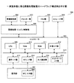
図7は、第1の実施形態に係る画像処理の例を示すシーケンスチャートである。尚、図7において、破線の矢印は、情報端末102への利用者による操作等を示す。
<Process flow>
(Image processing flow)
FIG. 7 is a sequence chart illustrating an example of image processing according to the first embodiment. In FIG. 7, a broken line arrow indicates an operation on the
ステップS701において、画像処理システム100は、例えば、利用者による、情報端末102にインストールされた画像処理システム100用のアプリ(画像処理プログラム)への開始操作等によって画像処理を開始する。
In step S <b> 701, the
ステップS702において、アプリの開始操作を受付けた情報端末102は、表示入力手段617に、利用者による入力用の画像処理装置(以下、入力機器と呼ぶ)及び出力用の画像処理装置(以下、出力機器と呼ぶ)の指定を促す機器特定画面を表示させる。
In step S <b> 702, the
ステップS703において、利用者は、情報端末102の表示入力手段617に表示された機器特定画面に従って、入力機器を指定する操作(特定操作)を行う。
In step S <b> 703, the user performs an operation (specific operation) for designating an input device according to the device identification screen displayed on the
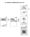
図8は、第1の実施形態に係る機器特定画面の例を示す図である。図7のステップS702において、情報端末102は、表示入力手段617に、例えば、図8に示す機器特定画面801を表示させる。機器特定画面801には、例えば、入力機器を選択するための「入力機器を選ぶ」ボタン802、出力機器を選択するための「出力機器を選ぶ」ボタン803、及び、「実行」ボタン804等が含まれる。
FIG. 8 is a diagram illustrating an example of a device identification screen according to the first embodiment. In step S702 of FIG. 7, the
図8の機器特定画面801において、例えば、「入力機器を選ぶ」ボタン802、又は「出力機器を選ぶ」ボタン803を押下(タップ)すると、表示入力手段617に、例えば、図8に示す選択方法指定画面805が表示される。選択方法指定画面805には、例えば、「直接接続」ボタン806、「タッチで接続」ボタン807、「二次元コードで接続」ボタン808等が含まれる。利用者は、この選択方法指定画面805から、入力機器、又は出力機器の選択方法を指定することができる。
When the “select input device” button 802 or the “select output device”
例えば、図8の選択方法指定画面805において、「直接接続」ボタン806が押下されると、情報端末102は、表示入力手段617に、図8に示すような、宛先設定画面809を表示させる。図8の宛先設定画面809において、利用者は、入力欄810に入力機器(又は出力機器)として利用したい画像処理装置104のIPアドレス、ホスト名、又はMACアドレス等を入力し、「接続」ボタン811を押下する。これにより、利用者は、入力機器(又は出力機器)として利用する画像処理装置104を指定することができる。
For example, when the “direct connection”
また、図8の選択方法指定画面805において、「タッチで接続」ボタン807が押下されると、情報端末102は、表示入力手段617に、例えば、図8に示すような、メッセージ画面812を表示させる。情報端末102は、このメッセージ画面812を表示させている間、近距離無線通信手段615により、例えば、NFC通信の電波を検知するモードに移行する。また、情報端末102は、指定対象となる画像処理装置104に近接すると、近距離無線通信手段615により、画像処理装置104から、画像処理装置104のIPアドレス、ホスト名、MACアドレス等の宛先情報(ネットワーク情報)を取得する。
When the “connect by touch”
尚、このとき、近距離無線通信手段615は、画像処理装置104から宛先情報だけではなく、後述する機器情報を合わせて取得するもの等であっても良い。また、情報端末102は、NFC通信に代えて、BLE通信等の他の近距離無線通信により、画像処理装置104から情報を取得するものであっても良い。
At this time, the short-range
また、図8の選択方法指定画面805において、「二次元コードで接続」ボタン808が押下されると、情報端末102は、表示入力手段617に、例えば、図8に示すような、二次元コード読取り画面813を表示させる。この状態で、撮像手段616で、二次元コードが撮影されると、機器特定手段611は、二次元コードに埋め込まれた画像処理装置104の宛先情報を取得する。尚、二次元コードには、宛先情報だけではなく、後述する機器情報も合わせて埋め込んでおくものであっても良い。
When the “connect with two-dimensional code”
ここで、図7に戻って、シーケンスチャートの説明を続ける。 Here, returning to FIG. 7, the description of the sequence chart will be continued.
ステップS704において、情報端末102は、ステップS703で特定(指定)された入力機器、例えば、電子ホワイトボード104−1に機器情報の取得要求を送信する。
In step S704, the
ステップS705において、情報端末102は、機器情報の取得要求を送信した入力機器、例えば、電子ホワイトボード104−1から返信された機器情報を取得する。
In step S705, the
ステップS706において、利用者は、情報端末102の表示入力手段617に表示された機器特定画面801により、出力機器の特定操作を行う。尚、出力機器の特定操作は、前述した入力機器の特定操作と同様である。
In step S <b> 706, the user performs an output device specifying operation on the
ステップS707において、情報端末102は、ステップS706で特定(指定)された出力機器、例えば、MFP104−2に機器情報の取得要求を送信する。
In step S707, the
ステップS708において、情報端末102は、機器情報の取得要求を送信した出力機器、例えば、MFP104−2から返信された機器情報を取得する。
In step S708, the
図9は、第1の実施形態に係る機器情報の例を示す図である。機器情報(ケーバビリティ情報)901は、例えば、「type」、「input」、「output」等の情報を含む。 FIG. 9 is a diagram illustrating an example of device information according to the first embodiment. The device information (capability information) 901 includes information such as “type”, “input”, and “output”, for example.
「type」情報は、画像処理装置104の種類を示す、例えば、電子ホワイトボード(Whiteboard)、MFP(mfp)、プロジェクタ(projector)等の情報である。
The “type” information is information such as an electronic whiteboard, an MFP (mfp), and a projector that indicates the type of the
「input」情報は、コンテンツ(入力データ)の入力の仕様を示す情報である。入力をサポートしない機器の機器情報には、「input」情報は含まれない。同様に、「output」情報は、コンテンツ(出力データ)の出力の仕様を示す情報である。出力をサポートしない機器の機器情報には、「output」情報は含まれない。 The “input” information is information indicating the specification of content (input data) input. The device information of devices that do not support input does not include “input” information. Similarly, “output” information is information indicating the output specification of content (output data). The device information of devices that do not support output does not include “output” information.
また、「input」情報、及び「output」情報は、例えば、「mime_type」情報、及び「settings」情報等を含む。 Further, “input” information and “output” information include, for example, “mem_type” information, “settings” information, and the like.
「mime_type」情報は、画像処理装置104が利用可能なコンテンツの形式(データ形式)の一覧情報である。「settings」情報は、利用可能な設定パラメータと、各設定パラメータの設定可能な範囲等を示す情報である。
“Mime_type” information is list information of content formats (data formats) that can be used by the
図9に示す機器情報901の例では、画像処理装置104は、MFPであり、入力(スキャン)用の画像のデータ形式として、PDF(application/pdf)、又はJPEG(image/jpeg)が利用可能である旨が記述されている。また、画像処理装置104の入力時の設定は、カラーモード(color_mode)、解像度(resolution)、原稿面(2sided)の指定が可能である旨が記述されている。
In the example of the
さらに、画像処理装置104は、出力(プリント)用の画像データ形式として、PDF(application/pdf)と、Postscript(application/postscript)が利用可能である旨が記述されている。さらにまた、画像処理装置104の出力時の設定は、カラーモード(color_mode)、解像度(resolution)、原稿面(2sided)、両面印刷(nup)、及び部数指定(copies)等の指定が可能である旨が記述されている。
Furthermore, it is described that the
再び図7に戻って、シーケンスチャートの説明を続ける。 Returning to FIG. 7 again, the description of the sequence chart will be continued.
図7のステップS709において、利用者は、例えば、情報端末102の表示入力手段617の機器特定画面801に含まれる「実行」ボタン804を押下すること等により、情報端末102に画像処理の実行を要求する実行操作を行う。
In step S709 in FIG. 7, the user executes image processing on the
尚、入力機器、及び出力機器から取得した機器情報が、「settings」情報を含む場合、ステップS709で実行操作を行う前に、情報端末102に設定画面を表示させ、設定パラメータを変更することができる。
When the device information acquired from the input device and the output device includes “settings” information, the setting screen may be displayed on the
図10は、第1の実施形態に係る設定画面の例を示す図である。図10の例では、設定画面1001は、「カラーモード」の設定欄1002、「解像度」の設定欄1003、「原稿面」の設定欄1004、「レイアウト」の設定欄1005、「部数」の設定欄1006等を含む。利用者は、各設定欄をタップすること等により、設定値を変更することができる。
FIG. 10 is a diagram illustrating an example of a setting screen according to the first embodiment. In the example of FIG. 10, the
例えば、利用者が、設定画面1001の「カラーモード」の設定欄1002をタップすると、カラーモードの設定画面1007が表示入力手段617に表示される。カラーモードの設定画面1007には、例えば、「カラー」の設定ボタン1008、及び「モノクロ」の設定ボタン1009が表示され、利用者は、いずれかをタップすることにより、カラーモードを選択することができる。設定が終わると、利用者は、例えば、設定画面1001をスワイプさせること等により、図8の機器特定画面801に復帰することができる。
For example, when the user taps the “color mode” setting field 1002 on the
再び図7に戻って、シーケンスチャートの説明を続ける。 Returning to FIG. 7 again, the description of the sequence chart will be continued.
図7のステップS709において、情報端末102への画像処理の実行操作が行われると、情報端末102は、中継サーバ101に指定情報を送信する(ステップS710)。
In step S709 in FIG. 7, when an image processing execution operation is performed on the
図11は、第1の実施形態に係る指定情報の例を示す図である。指定情報1101には、入力機器、及び出力機器に関する情報が指定されている。
FIG. 11 is a diagram illustrating an example of designation information according to the first embodiment. In the
図11において、入力機器(input)の情報には、画像処理装置の種類(type)、宛先情報(host)、利用可能なデータ形式の情報(mime_type)、設定情報(settings)等の情報が含まれている。また、出力用の画像処理装置(output)の情報には、画像処理装置の種類(type)、宛先情報(host)、利用可能なデータ形式の情報(mime_type)、設定情報(settings)等の情報が含まれている。 In FIG. 11, the information on the input device (input) includes information such as the type (type) of the image processing apparatus, destination information (host), information on the available data format (mime_type), and setting information (settings). It is. In addition, the output image processing apparatus (output) information includes information such as the type (type) of the image processing apparatus, destination information (host), information on available data formats (mime_type), and setting information (settings). It is included.
図11の例では、指定情報1101には、入力機器として、電子ホワイトボード104−1(IPアドレス:192.168.1.11、利用可能なデータ形式:JPEG、TIFF、設定:なし)が指定されている。また、指定情報1101には、出力機器として、MFP104−2(IPアドレス:192.168.1.12、利用可能なデータ形式:PDF、Postscript、設定:カラー、200dpi、片面印刷、2in1、2部)が指定されている。
In the example of FIG. 11, the
再び図7に戻って、シーケンスチャートの説明を続ける。 Returning to FIG. 7 again, the description of the sequence chart will be continued.
ステップS711において、中継サーバ101のデータ形式決定手段603は、指定情報に含まれる入力用の画像処理装置で利用可能なデータ形式の情報と、出力用の画像処理装置で利用可能なデータ形式の情報とに基づいて、入力データのデータ形式を決定する。
In step S711, the data
ステップS712において、中継サーバ101の入力データ取得手段604は、データ形式決定手段603によって決定されたデータ形式による入力データの取得を、入力機器(電子ホワイトボード104−1)に要求する。
In step S712, the input
ステップS713において、中継サーバ101の入力データ取得手段604は、入力機器から入力データを取得し、例えば、記憶手段607にコンテンツデータ609として記憶する。
In step S713, the input
ステップS714において、中継サーバ101の変換手段605は、必要に応じて、入力データ取得手段604が取得したコンテンツデータ609を、出力機器(MFP104−2)で利用可能なデータ形式に変換する。
In step S714, the
図12は、第1の実施形態に係る変換可能リストの例を示す図である。変換可能リスト1201には、変換手段605が変換可能なデータ形式の情報が記述されている。図12の例では、変換手段605は、JPEGからPDFへの変換、MSWORDからPDFへの変換、PDFからJPEGへの変換をサポートしていることを示している。
FIG. 12 is a diagram illustrating an example of a convertible list according to the first embodiment. The
図7のステップS715において、中継サーバ101の出力データ送信手段606は、出力機器(MFP104−2)に出力データの出力要求を送信し、続いて、ステップS716において、出力データを出力機器に送信する。
In step S715 of FIG. 7, the output
ステップS717において、中継サーバ101は、情報端末102に画像処理を完了したことを示す完了通知を送信し、ステップS718において、完了通知を受信した情報端末102は、表示入力手段617に完了画面を表示させる。
In step S717, the
上記処理により、入力機器(電子ホワイトボード104−1)から取得した入力データに基づく出力データが、出力機器(MFP104−2)に出力される。また、このとき、情報端末102には、入力データ及び出力データは格納されないので、情報流出のリスクを低減させることができる。
Through the above processing, output data based on the input data acquired from the input device (electronic whiteboard 104-1) is output to the output device (MFP 104-2). At this time, since the input data and the output data are not stored in the
ここで、図7のステップS711〜S714の決定処理及び変換処理について、詳しく説明する。 Here, the determination process and the conversion process in steps S711 to S714 in FIG. 7 will be described in detail.
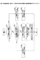
(決定処理及び変換処理)
図13は、第1の実施形態に係るデータ形式の決定処理及び変換処理のフローチャートである。
(Decision process and conversion process)
FIG. 13 is a flowchart of data format determination processing and conversion processing according to the first embodiment.
ステップS1301において、中継サーバ101は、例えば、情報端末102から受信した指定情報により、入力機器(入力用の画像処理装置)と、出力機器(出力用の画像処理装置)で同一のmime_typeがあるか否かを判断する。これにより、中継サーバ101は、入力機器と出力機器とで共通して利用可能なデータ形式があるか否かを判断する。
In step S1301, for example, according to the designation information received from the
ステップS1301で、入力機器と、出力機器で同一のmime_typeがある場合、中継サーバ101は、入力機器から、同一のmime_typeで入力データを取得する(ステップS1302)。例えば、入力機器と出力機器が、同一のmime_type「JPEG」に対応している場合、中継サーバ101は、図14(a)に示すような入力データの取得要求1401を入力機器に送信する。図14(a)の例では、入力データの取得要求1401は、入力データのデータ形式としてJPEG形式を指定する情報を含んでいる。
In step S1301, when the input device and the output device have the same mime_type, the
入力データの取得要求を受信した入力機器は、指定されたmime_typeであるJPEG形式で画像データを取得し、中継サーバ101へ送信する。また、中継サーバ101は、取得した、例えば、JPEG形式のデータを出力機器に出力させる(ステップ1303)。つまり、中継サーバ101は、入力機器と出力機器の両方で共通して利用可能なデータ形式がある場合、データ形式の変換を行わずに、出力機器に出力させる。
The input device that has received the input data acquisition request acquires the image data in the JPEG format that is the designated mime_type and transmits it to the
一方、ステップS1301で、入力機器と、出力機器で同一のmime_typeがない場合、中継サーバ101は、入力機器と出力機器で、変換可能なmime_typeの組合せがあるか否かを判断する(ステップS1304)。中継サーバ101は、変換手段605から、例えば、図12に示す変換可能リスト1201を取得して、入力機器と出力機器との間で、変換可能なmime_typeの組合せがあるか否かを判断する。
On the other hand, if the input device and the output device do not have the same mime_type in step S1301, the
ステップS1304において、入力機器と出力機器で、変換可能なmime_typeの組合せがない場合、ステップS1305へ移行する。ステップS1305では、中継サーバ101は、情報端末102に変換エラーを通知し(ステップS305)、処理を終了する。
If there is no mime_type combination that can be converted between the input device and the output device in step S1304, the process proceeds to step S1305. In step S1305, the
一方、ステップ1304において、入力機器と出力機器で、変換可能なmime_typeの組合せがある場合、ステップS1306〜S1306の処理を実行する。 On the other hand, if there is a mime_type combination that can be converted between the input device and the output device in step 1304, the processing in steps S1306 to S1306 is executed.
ステップS1306において、中継サーバ101は、入力機器から変換可能なmime_typeのデータを取得する。
In step S1306, the
ステップS1307において、中継サーバ101は、取得したデータを出力機器が利用可能なmime_typeのデータに変換する。
In step S1307, the
ステップS1308において、中継サーバ101は、出力機器が利用可能なmime_typeに変換されたデータを出力機器に出力させる。例えば、中継サーバ101は、図14(b)に示すような出力データの出力要求1402を出力機器に送信した後、出力データを出力機器に送信する。図14(b)の例では、出力機器に対して、中継サーバ101からPDF形式で出力データを受信し、カラー、200dpi、片面、2in1、2部の設定で画像形成(例えば印刷)を行うことを指示している。
In step S1308, the
以上、本実施形態に係る中継サーバ101は、情報端末102から受信した指定情報に基づいて、入力用の画像処理装置から入力データを取得し、取得した入力データに基づく出力データを出力用の画像処理装置に出力させる。従って、情報端末102は、画像処理の対象となる画像データを情報端末102に取得することなく、複数の画像処理装置104による画像処理を制御することができる。
As described above, the
これにより、スマートデバイス等の情報端末102を用いて、処理対象となるデータの情報流出を抑制しつつ、複数の画像処理装置104−1〜104−4による画像処理の制御を容易にする画像処理システム100を提供することができる。
As a result, image processing that facilitates control of image processing by the plurality of image processing apparatuses 104-1 to 104-4 while suppressing information leakage of data to be processed using the
[第2の実施形態]
第1の実施形態では、例えば、図7のステップS703〜S708において、入力機器と、出力機器を指定(特定)してから実行操作(ステップS709)を行っていた。しかし、入力用の画像処理装置の指定と、出力用の画像処理装置の指定は、別々に行うことも可能である。
[Second Embodiment]
In the first embodiment, for example, in steps S703 to S708 in FIG. 7, the execution operation (step S709) is performed after the input device and the output device are specified (specified). However, the designation of the input image processing apparatus and the designation of the output image processing apparatus can be performed separately.
<機能構成>
図15は、第2の実施形態に係る画像処理システムの機能構成図である。図15において、中継サーバ101は、図6に示す第1の実施形態の機能構成に加えて、識別子通知手段1501を有している。尚、他の構成は、第1の実施形態の機能構成と同様なので、ここでは差分を中心に説明を行う。
<Functional configuration>
FIG. 15 is a functional configuration diagram of the image processing system according to the second embodiment. In FIG. 15, the
識別子通知手段1501は、情報端末102から、入力用の画像処理装置を指定する指定情報を受信すると、受信した指定情報と、現在の処理を特定するための識別子(チケット)とを対応づけて、記憶手段607に入力機器情報1502として記憶する。また、識別子通知手段1501は、指定情報を送信した情報端末102に、現在の処理特定するための識別子を通知(送信)する。
When the
<処理の流れ>
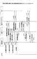
図16は、第2の実施形態に係る画像処理の例を示すシーケンスチャートである。
<Process flow>
FIG. 16 is a sequence chart illustrating an example of image processing according to the second embodiment.
ステップS1601において、利用者は、第1の実施形態と同様に、情報端末102の表示入力手段617に表示された機器特定画面に従って、入力機器を指定する操作(特定操作)を行う。
In step S1601, the user performs an operation (specific operation) for specifying an input device in accordance with the device specifying screen displayed on the
ステップS71602において、情報端末102は、第1の実施形態と同様に、ステップS1601で特定(指定)された入力用の画像処理装置、例えば、電子ホワイトボード104−1に機器情報の取得要求を送信する。
In step S71602, as in the first embodiment, the
ステップS1603において、情報端末102は第1の実施形態と同様に、機器情報の取得要求を送信した入力用の画像処理装置、例えば、電子ホワイトボード104−1から、機器情報を取得する。
In step S1603, as in the first embodiment, the
ステップS1604において、本実施形態では、利用者は、出力機器の特定操作を行わずに、入力機器の指定操作を行う。例えば、利用者は、図8の機器特定画面801において、出力機器の選択を行わずに「実行」ボタン804を押下することにより、入力機器の指定操作を行う。
In step S1604, in this embodiment, the user performs an input device designation operation without performing an output device specifying operation. For example, the user performs an input device designation operation by pressing the “execute”
ステップS1605において、利用者から、入力機器の指定操作を受付けた情報端末102は、中継サーバ101に、例えば、図17(a)に示すような、入力機器の指定情報1701を送信する。入力機器の指定情報1701は、第1の実施形態に係る指定情報1104とくらべて、「output」の項目を含まない構成となっている。
In step S <b> 1605, the
ステップS1606において、中継サーバ101は、情報端末102から、入力機器の指定情報を受信すると、例えば、図17の(b)に示すような、処理の識別情報1702を情報端末102に返信する。また、このとき、中継サーバ101は、情報端末102から受信した入力機器の指定情報に含まれる入力機器の情報と、情報端末102に返信した処理の識別情報1702とを対応づけて、記憶手段607に入力機器情報1502として記憶する。このとき、中継サーバ101は、入力機器からの入力データの取得を、行わなくても良い。尚、この処理の識別情報1802に含まれる「ticket」の値は、例えば、識別子通知手段1501によって、処理毎にユニークな値が生成される。
In step S <b> 1606, when the
ステップS1607において、利用者は、情報端末102の表示入力手段617に表示された機器特定画面に従って、出力機器の特定操作を行う。尚、この出力機器の特定操作は、例えば、図16のように、入力機器の指定操作に続いて行われるものであっても良いし、後で行われるものであっても良い。
In step S1607, the user performs an output device specifying operation according to the device specifying screen displayed on the
ステップS1608において、情報端末102は、ステップS1607で特定された出力機器、例えば、MFP104−2に機器情報の取得要求を送信する。
In step S1608, the
ステップS1609において、情報端末102は、機器情報の取得要求を送信した出力機器、例えば、MFP104−2から、機器情報を取得する。
In step S1609, the
ステップS1610において、利用者からの画像処理の実行操作を受付けると、画像処理システム100は、第1の実施形態と同様に、受信した指定情報に基づいて、画像処理を実行する(ステップS710〜S718)。
In step S1610, when an image processing execution operation is received from the user, the
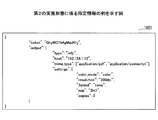
尚、このとき、情報端末102から中継サーバ101に送信される指定情報の例を、図18に示す。本実施形態に係る指定情報1801は、図11で示した第1の実施形態の指定情報1101における「input」の項目に代えて、ステップS1606で中継サーバ101から通知された処理の識別情報である「ticket」の項目が含まれている。
An example of the designation information transmitted from the
中継サーバ101は、この指定情報1801に含まれる「ticket」の情報と、記憶手段607に記憶した入力機器情報1502に基づいて、入力機器の機器情報を特定することができる。
The
上記処理により、利用者は、入力機器の指定と、出力機器の指定とを別のタイミングで行うことができるようになり、利便性を向上させることができる。 With the above processing, the user can specify the input device and the output device at different timings, and the convenience can be improved.
[第3の実施形態]
第3の実施形態では、中継サーバ101に、1つ以上の画像処理装置104を予め登録しておく場合の例について説明する。
[Third Embodiment]
In the third embodiment, an example in which one or more
<機能構成>
図19は、第3の実施形態に係る画像処理システムの機能構成図である。
<Functional configuration>
FIG. 19 is a functional configuration diagram of an image processing system according to the third embodiment.
(中継サーバの機能構成)
本実施形態に係る中継サーバ101は、図6に示す第1の実施形態に係る中継サーバ101の構成に加えて、機器情報取得手段1901、一覧情報送信手段1902を有している。尚、その他の構成は、第1の実施形態と同様なので、ここでは差分を中心に説明を行う。
(Functional configuration of relay server)
The
機器情報取得手段1901は、入力機器から入力機器の機器情報を取得し、出力機器から出力機器の機器情報を取得する。また、機器情報取得手段1901は、取得した機器情報を、例えば、記憶手段607に機器情報1903として記憶する。
The device
一覧情報送信手段1902は、情報端末102等からの要求に応じて、機器情報1903として記憶した1つ以上の画像処理装置104の一覧情報を情報端末102に送信する。
The list
尚、機器情報取得手段1901及び一覧情報送信手段1902は、例えば、図3のCPU301で動作するプログラムによって実現される。
Note that the device
(情報端末の機能構成)
本実施形態に係る情報端末102は、図6に示す第1の実施形態に係る情報端末102の構成に加えて、登録要求手段1904、及び一覧情報要求手段1905を有している。また、本実施形態に係る情報端末102は、第1の実施形態に係る情報端末102に含まれる機器情報取得手段612を有していなくても良い。尚、その他の構成は、第1の実施形態と同様なので、ここでは差分を中心に説明を行う。
(Functional configuration of information terminal)
The
登録要求手段1904は、中継サーバ101に画像処理装置104の登録処理を要求するための手段である。尚、画像処理装置104の登録処理については後述する。
Registration request means 1904 is a means for requesting the
一覧情報要求手段1905は、中継サーバ101に1つ以上の画像処理装置104の一覧情報を要求するための手段である。
A list
尚、登録要求手段1904及び一覧情報要求手段1905は、例えば、図4のCPU401で動作するプログラムによって実現される。
Note that the
<処理の流れ>
(登録処理)
図20は、第3の実施形態に係る登録処理の例を示すシーケンスチャートである。
<Process flow>
(registration process)
FIG. 20 is a sequence chart illustrating an example of registration processing according to the third embodiment.
ステップS2001において、利用者は、登録したい画像処理装置104、例えば、電子ホワイトボード104−1の登録操作を行う。登録操作は、例えば、図8に示す機器特定画面801に「登録機器を選ぶ」ボタンを追加し、この「登録機器を選ぶ」ボタンの押下等により行うことができる。
In step S2001, the user performs a registration operation for the
ステップS2002において、情報端末102は、利用者から、例えば、電子ホワイトボード104−1の登録操作を受付けると、登録要求手段1904により、中継サーバ101に電子ホワイトボード104−1の機器登録要求を送信する。
In step S2002, when the
ステップS2003において、中継サーバ101は、情報端末102から機器登録要求を受信すると、機器情報取得手段1901により、電子ホワイトボード104−1に機器情報の取得要求を送信する。
In step S2003, when the
ステップS2004において、中継サーバ101の機器情報取得手段1901は、電子ホワイトボード104−1から返信された機器情報を取得する。
In step S2004, the device
ステップS2005において、中継サーバ101の機器情報取得手段1901は、電子ホワイトボード104−1から取得した機器情報を、記憶手段607の機器情報1903に登録する。このとき、機器情報取得手段1901は、電子ホワイトボード104−1用のユニークな機器ID(例えば、「whiteboard1」)を生成し、生成した機器IDと、取得した機器情報とを対応づけて機器情報1903に登録する。
In step S2005, the device
ステップS2006において、中継サーバ101は、登録処理が完了したことを情報端末102に通知する。
In step S2006, the
ステップS2007において、情報端末102は、完了通知を受信すると、表示入力手段617に登録処理が完了したことを示す完了表示を行う。
In step S 2007, when the
同様にして、利用者は、複数の画像処理装置104を登録することができる。
Similarly, the user can register a plurality of
例えば、ステップS2008において、利用者は、次に登録したい画像処理装置104、例えば、MFP104−2の登録操作を行う。
For example, in step S2008, the user performs a registration operation for the
ステップS2009において、情報端末102は、利用者から、例えば、MFP104−2の登録操作を受付けると、登録要求手段1904により、中継サーバ101にMFP104−2の登録要求を送信する。
In step S2009, when the
ステップS2010において、中継サーバ101は、情報端末102から機器登録要求を受信すると、機器情報取得手段1901により、MFP104−2に機器情報の取得要求を送信する。
In step S2010, when the
ステップS2011において、中継サーバ101の機器情報取得手段1901は、MFP104−2から送信された機器情報を取得する。
In step S2011, the device
ステップS2012において、中継サーバ101の機器情報取得手段1901は、MFP104−2から取得した機器情報を、記憶手段607の機器情報1903に登録する。このとき、機器情報取得手段1901は、MFP104−2用のユニークな機器ID(例えば、「mfp1」)を生成し、生成した機器IDと、取得した機器情報とを対応づけて機器情報1903に登録する。
In step S2012, the device
ステップS2013において、中継サーバ101は、登録処理が完了したことを情報端末102に通知する。
In step S2013, the
ステップS2007において、情報端末102は、完了通知を受信すると、表示入力手段617に登録処理が完了したことを示す完了表示を行う。
In step S 2007, when the
(画像処理)
図21は、第3の実施形態に係る画像処理の例を示す図である。
(Image processing)
FIG. 21 is a diagram illustrating an example of image processing according to the third embodiment.
ステップS2101において、利用者は、情報端末102に対して、利用可能な機器一覧の表示操作を行う。
In step S <b> 2101, the user performs an operation for displaying a list of available devices on the
ステップS2102において、利用者から機器一覧の表示操作を受付けた情報端末102の一覧情報要求手段1905は、中継サーバ101に一覧情報の取得要求を送信する。
In step S2102, the list
ステップS2103において、一覧情報の取得要求を受信した中継サーバ101の一覧情報送信手段1902は、利用可能な1つ以上の画像処理装置104の一覧情報を情報端末102に送信し、情報端末102は、送信された一覧情報を取得する。このとき、中継サーバ101によって送信される一覧情報の例を図22に示す。一覧情報2201には、例えば、図20のステップS2205、2012で登録された画像処理装置104の機器情報と、画像処理装置104毎にユニークな機器IDとが含まれている。
In step S2103, the list
例えば、図22の例では、一覧情報2201には、MFP104−2の機器情報と、MFP104−2に対応する機器ID「mfp1」とが含まれている。また、一覧情報2201には、電子ホワイトボード104−1の機器情報と、電子ホワイトボード104−1に対応する機器ID「whiteboard1」とが含まれている。
For example, in the example of FIG. 22, the
図21に戻ってシーケンスチャートの説明を続ける。 Returning to FIG. 21, the description of the sequence chart will be continued.
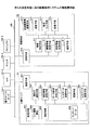
ステップS2104において、情報端末102は、表示入力手段617に、利用可能な1つ以上の画像処理装置104の機器IDと、そのアイコンとをGUI(Graphical User Interface)等に一覧表示する入出力機器の選択画面を表示させる。このとき、表示入力手段617に表示される入出力機器の選択画面の例を図23に示す。
In step S2104, the
図23の例では、情報端末102の表示入力手段617に表示された入出力機器の選択画面2301は、電子ホワイトボード104−1のアイコン及び機器ID「whiteboard1」、及びMFP104−2のアイコン及び機器ID「mfp1」を含む。さらに、選択画面2301は、一覧情報2201に含まれる他の画像処理装置104、例えば、プロジェクタ104−4のアイコン及び機器ID「projector1」等も含まれる。
In the example of FIG. 23, the input / output
図21のステップS2105において、利用者は、情報端末102の表示入力手段617に表示された選択画面2301で、入出力機器の選択操作を行う。例えば、図23において、電子ホワイトボード104−1から入力した画像データを、MFP104−2に出力させたい場合、電子ホワイトボードのアイコン2302を、MFPのアイコン2303にドラッグアンドドロップさせる。本実施形態では、例えば、このように、容易に入出力機器の選択を行うことが可能となる。
In step S2105 of FIG. 21, the user performs an input / output device selection operation on the
ステップS2105において、利用者からの画像処理の実行操作を受付けると、画像処理システム100は、第1の実施形態と同様に、受信した指定情報に基づいて、画像処理を実行する(ステップS710〜S718)。
In step S2105, when an image processing execution operation is accepted from the user, the
尚、このとき、情報端末102から中継サーバ101に送信される指定情報の例を、図24に示す。本実施形態に係る指定情報2401は、図11に示す第1の実施形態に係る指定情報1101の入力機器の宛先情報及び機器情報に代えて、入力機器の機器ID(入力用の画像処理装置104の識別情報)である「whiteboard1」を含む。また、指定情報2401は、図11に示す第1の実施形態に係る指定情報1101の出力機器の宛先情報及び機器情報に代えて、出力機器の機器ID(出力用の画像処理装置104の識別情報)である「mfp1」を含む。
At this time, an example of the designation information transmitted from the
本実施形態によれば、利用可能な1つ以上の画像処理装置104が、情報端末102の表示入力手段617に一覧表示されるので、入力機器及び出力機器の選択操作を容易にすることができる。
According to the present embodiment, since one or more available
<まとめ>
本発明の一実施形態に係る画像処理システム(100)は、1つ以上の画像処理装置(104)と、情報端末(102)と、前記1つ以上の画像処理装置(104)及び前記情報端末(102)と通信可能な情報処理装置(101)と、を含む。
<Summary>
An image processing system (100) according to an embodiment of the present invention includes one or more image processing devices (104), an information terminal (102), the one or more image processing devices (104), and the information terminal. (102) and an information processing apparatus (101) capable of communicating with the information processing apparatus (102).
また、前記情報端末(102)は、前記1つ以上の画像処理装置(104)の中から入力用の画像処理装置と出力用の画像処理装置とを指定する指定情報(1101等)を前記情報処理装置(101)に送信する指定情報送信手段(613)を有する。 Further, the information terminal (102) receives designation information (1101 etc.) for designating an input image processing apparatus and an output image processing apparatus from the one or more image processing apparatuses (104). There is designated information transmitting means (613) for transmitting to the processing device (101).
また、前記情報処理装置(101)は、前記情報端末(102)から受信した指定情報(1101等)に基づいて、前記入力用の画像処理装置から入力データを取得する入力データ取得手段(602)を有する。さらに、前記情報処理装置(101)は、前記受信した指定情報(1101等)に基づいて、前記取得した入力データに基づく出力データを前記出力用の画像処理装置に送信する出力データ送信手段(606)を有する。 Further, the information processing apparatus (101) acquires input data from the input image processing apparatus (602) based on the designation information (1101 etc.) received from the information terminal (102). Have Furthermore, the information processing apparatus (101) outputs output data based on the acquired input data to the output image processing apparatus (606) based on the received designation information (1101 etc.). ).
上記の構成により、画像処理システム(100)によれば、スマートデバイス等の情報端末(102)を用いて、処理対象となるデータの情報流出を抑制しつつ、複数の画像処理装置(104)による画像処理の制御を容易にすることができる。 With the above configuration, according to the image processing system (100), the information terminal (102) such as a smart device is used to suppress information leakage of data to be processed, and the plurality of image processing devices (104). Control of image processing can be facilitated.
100 画像処理システム
101 中継サーバ(情報処理装置)
102 情報端末
104 画像処理装置
104−1 電子ホワイトボード(画像処理装置の一例)
104−2 MFP(画像処理装置の一例)
104−3 プリンタ(画像処理装置の一例)
104−4 プロジェクタ(画像処理装置の一例)
603 データ形式決定手段(決定手段)
604 入力データ取得手段
605 変換手段
606 出力データ送信手段
607 記憶手段
612、1901 機器情報取得手段
613 指定情報送信手段
617 表示入力手段
1501 識別子通知手段(通知手段)
1902 一覧情報送信手段
100
102
104-2 MFP (an example of an image processing apparatus)
104-3 Printer (an example of an image processing apparatus)
104-4 Projector (an example of an image processing apparatus)
603 Data format determination means (determination means)
604 input data acquisition means 605 conversion means 606 output data transmission means 607 storage means 612, 1901 device information acquisition means 613 designation information transmission means 617 display input means 1501 identifier notification means (notification means)
1902 List information transmission means
Claims (8)
前記入力機器及び前記出力機器として利用可能な機器を含む複数の機器を示す画面を表示する表示手段と、
前記入力機器を、前記複数の機器から前記画面に対する第1の機器選択操作に基づいて特定し、前記出力機器を、前記複数の機器から前記第1の機器選択操作後の前記画面に対する第2の機器選択操作に基づいて特定する特定手段と、
前記第1の機器選択操作によって特定された第1の機器を識別する情報を前記入力機器として指定し、前記第2の機器選択操作によって特定された第2の機器を識別する情報を前記出力機器として指定する指定情報を前記情報処理装置に送信する送信手段と、
を有する情報端末。 An information terminal connected via a network to an input device that executes input processing and an information processing device that controls execution of image processing by an output device that executes output processing according to the input processing ,
Display means for displaying a screen showing a plurality of devices including devices usable as the input device and the output device ;
The input device is specified based on a first device selection operation for the screen from the plurality of devices, and the output device is specified as a second for the screen after the first device selection operation from the plurality of devices. Identifying means for identifying based on the device selection operation;
Information identifying the first device identified by the first device selection operation is designated as the input device , and information identifying the second device identified by the second device selection operation is the output device. and transmitting means for transmitting to the information processing apparatus designation information designating as,
An information terminal.
前記第2の機器選択操作は前記タッチ操作を起点としたスライド操作であることを特徴とする請求項1に記載の情報端末。 The first device selection operation is a touch operation of first touching the plurality of devices on the screen,
The information terminal according to claim 1, wherein the second device selection operation is a slide operation starting from the touch operation.
前記情報処理装置とネットワークを介して接続する情報端末とを含むシステムであって、
前記情報端末は、
前記入力機器及び前記出力機器として利用可能な機器を含む複数の機器を示す画面を表示する表示手段と、
前記入力機器を、前記複数の機器から前記画面に対する第1の機器選択操作に基づいて特定し、前記出力機器を、前記複数の機器から前記第1の機器選択操作後の前記画面に対する第2の機器選択操作に基づいて特定する特定手段と、
前記第1の機器選択操作によって特定された第1の機器を識別する情報を前記入力機器として指定し、前記第2の機器選択操作によって特定された第2の機器を識別する情報を前記出力機器として指定する指定情報を前記情報処理装置に送信する送信手段と、
を有することを特徴とするシステム。 An input device that executes input processing; an information processing device that controls execution of image processing by an output device that executes output processing according to the input processing ; and
A system including an information terminal connected to the information processing apparatus via a network,
The information terminal
Display means for displaying a screen showing a plurality of devices including devices usable as the input device and the output device ;
The input device is specified based on a first device selection operation for the screen from the plurality of devices, and the output device is specified as a second for the screen after the first device selection operation from the plurality of devices. Identifying means for identifying based on the device selection operation;
Information identifying the first device identified by the first device selection operation is designated as the input device , and information identifying the second device identified by the second device selection operation is the output device. and transmitting means for transmitting to the information processing apparatus designation information designating as,
The system characterized by having.
前記入力機器を指定する情報に基づいて前記入力機器に処理の要求をする第1の要求手段と、
前記出力機器を指定する情報に基づいて前記出力機器に、前記入力機器による処理結果に応じた処理の要求を行う第2の要求手段と、
を有することを特徴とする請求項5に記載のシステム。 The information processing apparatus includes:
First request means for requesting the input device to process based on information specifying the input device;
Second request means for making a request for processing according to a processing result by the input device to the output device based on information designating the output device;
The system of claim 5, comprising:
前記入力機器及び前記出力機器として利用可能な機器を含む複数の機器を示す画面を表示する表示手段と、
前記入力機器を、前記複数の機器から前記画面に対する第1の機器選択操作に基づいて特定し、前記出力機器を、前記複数の機器から前記第1の機器選択操作後の前記画面に対する第2の機器選択操作に基づいて特定する特定手段と、
前記第1の機器選択操作によって特定された第1の機器を識別する情報を前記入力機器として指定し、前記第2の機器選択操作によって特定された第2の機器を識別する情報を前記出力機器として指定する指定情報を前記情報処理装置に送信する送信手段と、
として機能させるためのプログラム。 An information terminal connected via an input processing device that executes input processing and an information processing device that controls execution of image processing by the output device that executes output processing according to the input processing ;
Display means for displaying a screen showing a plurality of devices including devices usable as the input device and the output device ;
The input device is specified based on a first device selection operation for the screen from the plurality of devices, and the output device is specified as a second for the screen after the first device selection operation from the plurality of devices. Identifying means for identifying based on the device selection operation;
Information identifying the first device identified by the first device selection operation is designated as the input device , and information identifying the second device identified by the second device selection operation is the output device. and transmitting means for transmitting to the information processing apparatus designation information designating as,
Program to function as.
前記入力機器及び前記出力機器として利用可能な機器を含む複数の機器を示す画面を表示する表示ステップと、
前記入力機器を、前記複数の機器から前記画面に対する第1の機器選択操作に基づいて特定し、前記出力機器を、前記複数の機器から前記第1の機器選択操作後の前記画面に対する第2の機器選択操作に基づいて特定する特定ステップと、
前記第1の機器選択操作によって特定された第1の機器を識別する情報を前記入力機器として指定し、前記第2の機器選択操作によって特定された第2の機器を識別する情報を前記出力機器として指定する指定情報を前記情報処理装置に送信する送信ステップと、
を含む、情報処理方法。 An input device that executes input processing, an information processing device that controls execution of image processing by an output device that executes output processing according to the input processing, and an information terminal connected to the information processing device via a network An information processing method using a system including:
A display step for displaying a screen showing a plurality of devices including the input device and a device usable as the output device ;
The input device is specified based on a first device selection operation for the screen from the plurality of devices, and the output device is specified as a second for the screen after the first device selection operation from the plurality of devices. A specific step of identifying based on the device selection operation;
Information identifying the first device identified by the first device selection operation is designated as the input device , and information identifying the second device identified by the second device selection operation is the output device. designation information designating a transmission step of transmitting to the information processing apparatus as,
Including an information processing method.
Priority Applications (3)
| Application Number | Priority Date | Filing Date | Title |
|---|---|---|---|
| JP2015055965A JP6233338B2 (en) | 2015-03-19 | 2015-03-19 | Information terminal, system, information processing method, and program |
| US15/068,856 US9904495B2 (en) | 2015-03-19 | 2016-03-14 | Image processing system, image processing method, and information terminal |
| US15/869,660 US10331388B2 (en) | 2015-03-19 | 2018-01-12 | Image processing system, image processing method, and non-transitory storage medium storing image processing program |
Applications Claiming Priority (1)
| Application Number | Priority Date | Filing Date | Title |
|---|---|---|---|
| JP2015055965A JP6233338B2 (en) | 2015-03-19 | 2015-03-19 | Information terminal, system, information processing method, and program |
Related Child Applications (1)
| Application Number | Title | Priority Date | Filing Date |
|---|---|---|---|
| JP2017207015A Division JP6477827B2 (en) | 2017-10-26 | 2017-10-26 | Information terminal, system, program, and method |
Publications (3)
| Publication Number | Publication Date |
|---|---|
| JP2016177431A JP2016177431A (en) | 2016-10-06 |
| JP2016177431A5 JP2016177431A5 (en) | 2017-05-18 |
| JP6233338B2 true JP6233338B2 (en) | 2017-11-22 |
Family
ID=56924728
Family Applications (1)
| Application Number | Title | Priority Date | Filing Date |
|---|---|---|---|
| JP2015055965A Active JP6233338B2 (en) | 2015-03-19 | 2015-03-19 | Information terminal, system, information processing method, and program |
Country Status (2)
| Country | Link |
|---|---|
| US (2) | US9904495B2 (en) |
| JP (1) | JP6233338B2 (en) |
Families Citing this family (5)
| Publication number | Priority date | Publication date | Assignee | Title |
|---|---|---|---|---|
| JP6635769B2 (en) * | 2015-11-28 | 2020-01-29 | キヤノン株式会社 | Communication device, communication device control method, and program |
| JP6957855B2 (en) * | 2016-10-06 | 2021-11-02 | 富士フイルムビジネスイノベーション株式会社 | Information processing equipment, information processing systems and programs |
| US11163432B2 (en) | 2018-01-30 | 2021-11-02 | Ricoh Company, Ltd. | Information processing system, electronic blackboard apparatus, and recording medium |
| US10353649B1 (en) * | 2018-06-25 | 2019-07-16 | Xerox Corporation | Systems and methods for printing a document and related referenced content |
| JP6823628B2 (en) * | 2018-09-14 | 2021-02-03 | 株式会社Tbsテレビ | Drawing system, server, and how to send drawing command information |
Family Cites Families (20)
| Publication number | Priority date | Publication date | Assignee | Title |
|---|---|---|---|---|
| US6718378B1 (en) | 1999-04-30 | 2004-04-06 | Canon Kabushiki Kaisha | Device management information processing apparatus method and storage medium |
| US7593983B2 (en) * | 1999-04-30 | 2009-09-22 | Canon Kabushiki Kaisha | Data processing apparatus, data processing method, and storage medium storing computer-readable program |
| JP2001014255A (en) * | 1999-04-30 | 2001-01-19 | Canon Inc | Device and method for data processing, and storage medium |
| JP2001344162A (en) | 2000-05-31 | 2001-12-14 | Canon Inc | Network virtual multifunction machine controller, network virtual multifunction machine controlling method, and storage medium |
| US7142333B2 (en) * | 2001-06-21 | 2006-11-28 | Hewlett-Packard Development Company, L.P. | System and method for wirelessly initiated document scanning and transmission |
| US7409452B2 (en) * | 2003-02-28 | 2008-08-05 | Xerox Corporation | Method and apparatus for controlling document service requests from a mobile device |
| US8237949B2 (en) * | 2004-05-18 | 2012-08-07 | Sharp Laboratories Of America, Inc. | System and method for combining at a single location selection of image finishing operations of multiple devices |
| JP4951392B2 (en) | 2007-04-18 | 2012-06-13 | 株式会社リコー | Information processing apparatus, program, and recording medium |
| JP5321120B2 (en) | 2008-04-08 | 2013-10-23 | 株式会社リコー | Information processing apparatus, information processing method, and recording medium |
| JP5278047B2 (en) | 2009-03-04 | 2013-09-04 | 株式会社リコー | Information processing apparatus, program, and computer-readable recording medium |
| JP2011044040A (en) * | 2009-08-21 | 2011-03-03 | Fujitsu Ltd | Display device, device linkage system, device linkage control method and device linkage control program |
| JP5499584B2 (en) | 2009-09-09 | 2014-05-21 | 株式会社リコー | Print control program, information processing apparatus, and recording medium |
| JP5790143B2 (en) | 2011-05-18 | 2015-10-07 | 株式会社リコー | Information processing apparatus and program |
| JP5870527B2 (en) | 2011-07-26 | 2016-03-01 | 株式会社リコー | Output distribution system, output distribution device, output destination information providing device, and recording medium |
| JP5945916B2 (en) * | 2012-03-02 | 2016-07-05 | 日本電気株式会社 | Information processing system, information processing method, portable terminal, server, control method and control program thereof |
| JP5915278B2 (en) | 2012-03-13 | 2016-05-11 | 株式会社リコー | Program, information processing apparatus, storage medium |
| US9124846B2 (en) * | 2012-06-21 | 2015-09-01 | Toshiba Tec Kabushiki Kaisha | Mobile device directed multifunction device scanning to cloud storage |
| JP2014179014A (en) | 2013-03-15 | 2014-09-25 | Ricoh Co Ltd | Input output system, input output method, portable terminal, and program |
| JP6330361B2 (en) | 2013-03-27 | 2018-05-30 | 株式会社リコー | Print control program, information processing apparatus, and print system |
| JP6318469B2 (en) | 2013-05-10 | 2018-05-09 | 株式会社リコー | Service providing system and service providing method |
-
2015
- 2015-03-19 JP JP2015055965A patent/JP6233338B2/en active Active
-
2016
- 2016-03-14 US US15/068,856 patent/US9904495B2/en active Active
-
2018
- 2018-01-12 US US15/869,660 patent/US10331388B2/en not_active Expired - Fee Related
Also Published As
| Publication number | Publication date |
|---|---|
| US20180136886A1 (en) | 2018-05-17 |
| US20160274834A1 (en) | 2016-09-22 |
| US9904495B2 (en) | 2018-02-27 |
| JP2016177431A (en) | 2016-10-06 |
| US10331388B2 (en) | 2019-06-25 |
Similar Documents
| Publication | Publication Date | Title |
|---|---|---|
| JP6544976B2 (en) | Communication system, image processing apparatus and control method therefor, and program | |
| US9467590B2 (en) | Image processing system, device, and method that deletes or prohibits reading of destination information | |
| JP6233338B2 (en) | Information terminal, system, information processing method, and program | |
| JP5629621B2 (en) | Image forming apparatus, image forming processing system, image forming processing method, and computer-readable recording medium on which the program is recorded | |
| JP6098588B2 (en) | Printing system, portable terminal device and printing control program | |
| JP2016168708A (en) | Image processing device and image processing system | |
| US9253362B2 (en) | Information processing apparatus and non-transitory storage medium storing instructions executable by information processing apparatus | |
| JP2017034457A (en) | Information processing device, information processing device control method, and program | |
| JP6403642B2 (en) | Image forming system | |
| JP6477827B2 (en) | Information terminal, system, program, and method | |
| KR20190113577A (en) | Printing system, printing method, image forming apparatus and method for controlling the same, and computer program | |
| JP7205564B2 (en) | programs and mobile devices | |
| US9749481B2 (en) | Image processing apparatus capable of transmitting image data, control method therefor, and storage medium storing control program therefor | |
| JP2018045556A (en) | Processing apparatus and image forming apparatus | |
| US9883059B2 (en) | Image forming apparatus and terminal apparatus using short-range communication for retrieving image data from a network apparatus, displaying the image data on the terminal apparatus and printing the image data on the image forming apparatus | |
| JP2019201410A (en) | Communication system, image processing device, control method thereof, and program | |
| JP6598622B2 (en) | Image forming apparatus, information processing method, and program | |
| JP6150643B2 (en) | Image processing apparatus, authentication method thereof, and program | |
| JP5476200B2 (en) | Image reading apparatus and image reading system | |
| JP6910488B2 (en) | Communication system, image processing device and its control method, and program | |
| US10477062B2 (en) | Image forming apparatus for managing substantially simultaneous image processing requests | |
| JP7322373B2 (en) | Information processing apparatus, information processing method, information processing program, and image forming system | |
| JP6724386B2 (en) | Program, mobile terminal, and system | |
| JP2016018226A (en) | User terminal, image forming apparatus, server device, printing system, user terminal control method, image forming apparatus control method, server device control method, and program | |
| JP2020201963A (en) | Shared terminal, communication system, image transmission method, and program |
Legal Events
| Date | Code | Title | Description |
|---|---|---|---|
| A521 | Written amendment |
Free format text: JAPANESE INTERMEDIATE CODE: A523 Effective date: 20170329 |
|
| A621 | Written request for application examination |
Free format text: JAPANESE INTERMEDIATE CODE: A621 Effective date: 20170329 |
|
| A871 | Explanation of circumstances concerning accelerated examination |
Free format text: JAPANESE INTERMEDIATE CODE: A871 Effective date: 20170329 |
|
| A975 | Report on accelerated examination |
Free format text: JAPANESE INTERMEDIATE CODE: A971005 Effective date: 20170407 |
|
| A131 | Notification of reasons for refusal |
Free format text: JAPANESE INTERMEDIATE CODE: A131 Effective date: 20170425 |
|
| A521 | Written amendment |
Free format text: JAPANESE INTERMEDIATE CODE: A523 Effective date: 20170622 |
|
| A131 | Notification of reasons for refusal |
Free format text: JAPANESE INTERMEDIATE CODE: A131 Effective date: 20170711 |
|
| A521 | Written amendment |
Free format text: JAPANESE INTERMEDIATE CODE: A523 Effective date: 20170911 |
|
| TRDD | Decision of grant or rejection written | ||
| A01 | Written decision to grant a patent or to grant a registration (utility model) |
Free format text: JAPANESE INTERMEDIATE CODE: A01 Effective date: 20170926 |
|
| A61 | First payment of annual fees (during grant procedure) |
Free format text: JAPANESE INTERMEDIATE CODE: A61 Effective date: 20171009 |
|
| R151 | Written notification of patent or utility model registration |
Ref document number: 6233338 Country of ref document: JP Free format text: JAPANESE INTERMEDIATE CODE: R151 |