JP6232878B2 - Power storage system - Google Patents
Power storage system Download PDFInfo
- Publication number
- JP6232878B2 JP6232878B2 JP2013196645A JP2013196645A JP6232878B2 JP 6232878 B2 JP6232878 B2 JP 6232878B2 JP 2013196645 A JP2013196645 A JP 2013196645A JP 2013196645 A JP2013196645 A JP 2013196645A JP 6232878 B2 JP6232878 B2 JP 6232878B2
- Authority
- JP
- Japan
- Prior art keywords
- battery
- engine
- temperature
- vehicle
- charging
- Prior art date
- Legal status (The legal status is an assumption and is not a legal conclusion. Google has not performed a legal analysis and makes no representation as to the accuracy of the status listed.)
- Active
Links
Images


Classifications
-
- B—PERFORMING OPERATIONS; TRANSPORTING
- B60—VEHICLES IN GENERAL
- B60L—PROPULSION OF ELECTRICALLY-PROPELLED VEHICLES; SUPPLYING ELECTRIC POWER FOR AUXILIARY EQUIPMENT OF ELECTRICALLY-PROPELLED VEHICLES; ELECTRODYNAMIC BRAKE SYSTEMS FOR VEHICLES IN GENERAL; MAGNETIC SUSPENSION OR LEVITATION FOR VEHICLES; MONITORING OPERATING VARIABLES OF ELECTRICALLY-PROPELLED VEHICLES; ELECTRIC SAFETY DEVICES FOR ELECTRICALLY-PROPELLED VEHICLES
- B60L53/00—Methods of charging batteries, specially adapted for electric vehicles; Charging stations or on-board charging equipment therefor; Exchange of energy storage elements in electric vehicles
- B60L53/10—Methods of charging batteries, specially adapted for electric vehicles; Charging stations or on-board charging equipment therefor; Exchange of energy storage elements in electric vehicles characterised by the energy transfer between the charging station and the vehicle
- B60L53/14—Conductive energy transfer
-
- B—PERFORMING OPERATIONS; TRANSPORTING
- B60—VEHICLES IN GENERAL
- B60L—PROPULSION OF ELECTRICALLY-PROPELLED VEHICLES; SUPPLYING ELECTRIC POWER FOR AUXILIARY EQUIPMENT OF ELECTRICALLY-PROPELLED VEHICLES; ELECTRODYNAMIC BRAKE SYSTEMS FOR VEHICLES IN GENERAL; MAGNETIC SUSPENSION OR LEVITATION FOR VEHICLES; MONITORING OPERATING VARIABLES OF ELECTRICALLY-PROPELLED VEHICLES; ELECTRIC SAFETY DEVICES FOR ELECTRICALLY-PROPELLED VEHICLES
- B60L50/00—Electric propulsion with power supplied within the vehicle
- B60L50/50—Electric propulsion with power supplied within the vehicle using propulsion power supplied by batteries or fuel cells
- B60L50/60—Electric propulsion with power supplied within the vehicle using propulsion power supplied by batteries or fuel cells using power supplied by batteries
- B60L50/61—Electric propulsion with power supplied within the vehicle using propulsion power supplied by batteries or fuel cells using power supplied by batteries by batteries charged by engine-driven generators, e.g. series hybrid electric vehicles
-
- B—PERFORMING OPERATIONS; TRANSPORTING
- B60—VEHICLES IN GENERAL
- B60L—PROPULSION OF ELECTRICALLY-PROPELLED VEHICLES; SUPPLYING ELECTRIC POWER FOR AUXILIARY EQUIPMENT OF ELECTRICALLY-PROPELLED VEHICLES; ELECTRODYNAMIC BRAKE SYSTEMS FOR VEHICLES IN GENERAL; MAGNETIC SUSPENSION OR LEVITATION FOR VEHICLES; MONITORING OPERATING VARIABLES OF ELECTRICALLY-PROPELLED VEHICLES; ELECTRIC SAFETY DEVICES FOR ELECTRICALLY-PROPELLED VEHICLES
- B60L58/00—Methods or circuit arrangements for monitoring or controlling batteries or fuel cells, specially adapted for electric vehicles
- B60L58/10—Methods or circuit arrangements for monitoring or controlling batteries or fuel cells, specially adapted for electric vehicles for monitoring or controlling batteries
- B60L58/12—Methods or circuit arrangements for monitoring or controlling batteries or fuel cells, specially adapted for electric vehicles for monitoring or controlling batteries responding to state of charge [SoC]
-
- B—PERFORMING OPERATIONS; TRANSPORTING
- B60—VEHICLES IN GENERAL
- B60W—CONJOINT CONTROL OF VEHICLE SUB-UNITS OF DIFFERENT TYPE OR DIFFERENT FUNCTION; CONTROL SYSTEMS SPECIALLY ADAPTED FOR HYBRID VEHICLES; ROAD VEHICLE DRIVE CONTROL SYSTEMS FOR PURPOSES NOT RELATED TO THE CONTROL OF A PARTICULAR SUB-UNIT
- B60W10/00—Conjoint control of vehicle sub-units of different type or different function
- B60W10/04—Conjoint control of vehicle sub-units of different type or different function including control of propulsion units
- B60W10/06—Conjoint control of vehicle sub-units of different type or different function including control of propulsion units including control of combustion engines
-
- B—PERFORMING OPERATIONS; TRANSPORTING
- B60—VEHICLES IN GENERAL
- B60W—CONJOINT CONTROL OF VEHICLE SUB-UNITS OF DIFFERENT TYPE OR DIFFERENT FUNCTION; CONTROL SYSTEMS SPECIALLY ADAPTED FOR HYBRID VEHICLES; ROAD VEHICLE DRIVE CONTROL SYSTEMS FOR PURPOSES NOT RELATED TO THE CONTROL OF A PARTICULAR SUB-UNIT
- B60W10/00—Conjoint control of vehicle sub-units of different type or different function
- B60W10/04—Conjoint control of vehicle sub-units of different type or different function including control of propulsion units
- B60W10/08—Conjoint control of vehicle sub-units of different type or different function including control of propulsion units including control of electric propulsion units, e.g. motors or generators
-
- B—PERFORMING OPERATIONS; TRANSPORTING
- B60—VEHICLES IN GENERAL
- B60W—CONJOINT CONTROL OF VEHICLE SUB-UNITS OF DIFFERENT TYPE OR DIFFERENT FUNCTION; CONTROL SYSTEMS SPECIALLY ADAPTED FOR HYBRID VEHICLES; ROAD VEHICLE DRIVE CONTROL SYSTEMS FOR PURPOSES NOT RELATED TO THE CONTROL OF A PARTICULAR SUB-UNIT
- B60W10/00—Conjoint control of vehicle sub-units of different type or different function
- B60W10/24—Conjoint control of vehicle sub-units of different type or different function including control of energy storage means
- B60W10/26—Conjoint control of vehicle sub-units of different type or different function including control of energy storage means for electrical energy, e.g. batteries or capacitors
-
- B—PERFORMING OPERATIONS; TRANSPORTING
- B60—VEHICLES IN GENERAL
- B60W—CONJOINT CONTROL OF VEHICLE SUB-UNITS OF DIFFERENT TYPE OR DIFFERENT FUNCTION; CONTROL SYSTEMS SPECIALLY ADAPTED FOR HYBRID VEHICLES; ROAD VEHICLE DRIVE CONTROL SYSTEMS FOR PURPOSES NOT RELATED TO THE CONTROL OF A PARTICULAR SUB-UNIT
- B60W20/00—Control systems specially adapted for hybrid vehicles
- B60W20/10—Controlling the power contribution of each of the prime movers to meet required power demand
- B60W20/13—Controlling the power contribution of each of the prime movers to meet required power demand in order to stay within battery power input or output limits; in order to prevent overcharging or battery depletion
-
- B—PERFORMING OPERATIONS; TRANSPORTING
- B60—VEHICLES IN GENERAL
- B60W—CONJOINT CONTROL OF VEHICLE SUB-UNITS OF DIFFERENT TYPE OR DIFFERENT FUNCTION; CONTROL SYSTEMS SPECIALLY ADAPTED FOR HYBRID VEHICLES; ROAD VEHICLE DRIVE CONTROL SYSTEMS FOR PURPOSES NOT RELATED TO THE CONTROL OF A PARTICULAR SUB-UNIT
- B60W30/00—Purposes of road vehicle drive control systems not related to the control of a particular sub-unit, e.g. of systems using conjoint control of vehicle sub-units, or advanced driver assistance systems for ensuring comfort, stability and safety or drive control systems for propelling or retarding the vehicle
- B60W30/18—Propelling the vehicle
- B60W30/192—Mitigating problems related to power-up or power-down of the driveline, e.g. start-up of a cold engine
-
- B—PERFORMING OPERATIONS; TRANSPORTING
- B60—VEHICLES IN GENERAL
- B60W—CONJOINT CONTROL OF VEHICLE SUB-UNITS OF DIFFERENT TYPE OR DIFFERENT FUNCTION; CONTROL SYSTEMS SPECIALLY ADAPTED FOR HYBRID VEHICLES; ROAD VEHICLE DRIVE CONTROL SYSTEMS FOR PURPOSES NOT RELATED TO THE CONTROL OF A PARTICULAR SUB-UNIT
- B60W2710/00—Output or target parameters relating to a particular sub-units
- B60W2710/06—Combustion engines, Gas turbines
- B60W2710/0688—Engine temperature
-
- B—PERFORMING OPERATIONS; TRANSPORTING
- B60—VEHICLES IN GENERAL
- B60W—CONJOINT CONTROL OF VEHICLE SUB-UNITS OF DIFFERENT TYPE OR DIFFERENT FUNCTION; CONTROL SYSTEMS SPECIALLY ADAPTED FOR HYBRID VEHICLES; ROAD VEHICLE DRIVE CONTROL SYSTEMS FOR PURPOSES NOT RELATED TO THE CONTROL OF A PARTICULAR SUB-UNIT
- B60W2710/00—Output or target parameters relating to a particular sub-units
- B60W2710/24—Energy storage means
- B60W2710/242—Energy storage means for electrical energy
- B60W2710/246—Temperature
-
- Y—GENERAL TAGGING OF NEW TECHNOLOGICAL DEVELOPMENTS; GENERAL TAGGING OF CROSS-SECTIONAL TECHNOLOGIES SPANNING OVER SEVERAL SECTIONS OF THE IPC; TECHNICAL SUBJECTS COVERED BY FORMER USPC CROSS-REFERENCE ART COLLECTIONS [XRACs] AND DIGESTS
- Y02—TECHNOLOGIES OR APPLICATIONS FOR MITIGATION OR ADAPTATION AGAINST CLIMATE CHANGE
- Y02T—CLIMATE CHANGE MITIGATION TECHNOLOGIES RELATED TO TRANSPORTATION
- Y02T10/00—Road transport of goods or passengers
- Y02T10/60—Other road transportation technologies with climate change mitigation effect
- Y02T10/62—Hybrid vehicles
-
- Y—GENERAL TAGGING OF NEW TECHNOLOGICAL DEVELOPMENTS; GENERAL TAGGING OF CROSS-SECTIONAL TECHNOLOGIES SPANNING OVER SEVERAL SECTIONS OF THE IPC; TECHNICAL SUBJECTS COVERED BY FORMER USPC CROSS-REFERENCE ART COLLECTIONS [XRACs] AND DIGESTS
- Y02—TECHNOLOGIES OR APPLICATIONS FOR MITIGATION OR ADAPTATION AGAINST CLIMATE CHANGE
- Y02T—CLIMATE CHANGE MITIGATION TECHNOLOGIES RELATED TO TRANSPORTATION
- Y02T10/00—Road transport of goods or passengers
- Y02T10/60—Other road transportation technologies with climate change mitigation effect
- Y02T10/70—Energy storage systems for electromobility, e.g. batteries
-
- Y—GENERAL TAGGING OF NEW TECHNOLOGICAL DEVELOPMENTS; GENERAL TAGGING OF CROSS-SECTIONAL TECHNOLOGIES SPANNING OVER SEVERAL SECTIONS OF THE IPC; TECHNICAL SUBJECTS COVERED BY FORMER USPC CROSS-REFERENCE ART COLLECTIONS [XRACs] AND DIGESTS
- Y02—TECHNOLOGIES OR APPLICATIONS FOR MITIGATION OR ADAPTATION AGAINST CLIMATE CHANGE
- Y02T—CLIMATE CHANGE MITIGATION TECHNOLOGIES RELATED TO TRANSPORTATION
- Y02T10/00—Road transport of goods or passengers
- Y02T10/60—Other road transportation technologies with climate change mitigation effect
- Y02T10/7072—Electromobility specific charging systems or methods for batteries, ultracapacitors, supercapacitors or double-layer capacitors
-
- Y—GENERAL TAGGING OF NEW TECHNOLOGICAL DEVELOPMENTS; GENERAL TAGGING OF CROSS-SECTIONAL TECHNOLOGIES SPANNING OVER SEVERAL SECTIONS OF THE IPC; TECHNICAL SUBJECTS COVERED BY FORMER USPC CROSS-REFERENCE ART COLLECTIONS [XRACs] AND DIGESTS
- Y02—TECHNOLOGIES OR APPLICATIONS FOR MITIGATION OR ADAPTATION AGAINST CLIMATE CHANGE
- Y02T—CLIMATE CHANGE MITIGATION TECHNOLOGIES RELATED TO TRANSPORTATION
- Y02T90/00—Enabling technologies or technologies with a potential or indirect contribution to GHG emissions mitigation
- Y02T90/10—Technologies relating to charging of electric vehicles
- Y02T90/14—Plug-in electric vehicles
-
- Y—GENERAL TAGGING OF NEW TECHNOLOGICAL DEVELOPMENTS; GENERAL TAGGING OF CROSS-SECTIONAL TECHNOLOGIES SPANNING OVER SEVERAL SECTIONS OF THE IPC; TECHNICAL SUBJECTS COVERED BY FORMER USPC CROSS-REFERENCE ART COLLECTIONS [XRACs] AND DIGESTS
- Y10—TECHNICAL SUBJECTS COVERED BY FORMER USPC
- Y10S—TECHNICAL SUBJECTS COVERED BY FORMER USPC CROSS-REFERENCE ART COLLECTIONS [XRACs] AND DIGESTS
- Y10S903/00—Hybrid electric vehicles, HEVS
- Y10S903/902—Prime movers comprising electrical and internal combustion motors
- Y10S903/903—Prime movers comprising electrical and internal combustion motors having energy storing means, e.g. battery, capacitor
- Y10S903/93—Conjoint control of different elements
Description
本発明は、バッテリから供給される電力によって駆動する走行用のモータとエンジンを備え、外部電源から供給される電力を充電可能なハイブリッド車両の蓄電システムに関する。 The present invention relates to a power storage system for a hybrid vehicle that includes a traveling motor and an engine that are driven by electric power supplied from a battery and is capable of charging electric power supplied from an external power source.
ハイブリッド車両は、車両走行の駆動源として走行用のモータ及びエンジンを備えており、エンジン及び走行用のモータのいずれか一方もしくは両方を駆動源として走行することができる。 The hybrid vehicle includes a traveling motor and an engine as a driving source for traveling the vehicle, and can travel using either one or both of the engine and the traveling motor as a driving source.
近年では、プラグインハイブリッド車両が登場し、走行用のモータに電力を供給するバッテリに、外部電源から供給される電力を充電することができる。特許文献1では、外部電源による充電完了後の車両走行において、エンジンが駆動される機会を抑制しながら、バッテリの充電容量(SOC)が所定値に低下するまでバッテリに蓄えられた電力を積極的に使用した走行モード(CDモード)で車両制御を行い、燃費を向上させている。燃費を向上させるためには、CDモード中にエンジンが駆動される機会を抑制する必要がある。 In recent years, a plug-in hybrid vehicle has appeared, and a battery that supplies power to a motor for traveling can be charged with power supplied from an external power source. In Patent Document 1, the electric power stored in the battery is positively maintained until the charge capacity (SOC) of the battery is reduced to a predetermined value while suppressing the opportunity of driving the engine during vehicle travel after completion of charging by the external power source. The vehicle control is performed in the driving mode (CD mode) used for the vehicle to improve fuel efficiency. In order to improve the fuel consumption, it is necessary to suppress the chance that the engine is driven during the CD mode.
特許文献2では、外部充電中にエンジンを加熱することでエンジンの温度(エンジン冷却液の温度)を上げている。外部充電中に予めエンジンを加熱しておくことで、車両走行時にエンジンを暖機運転するためにエンジンが駆動される機会を抑制している。 In Patent Document 2, the engine temperature (engine coolant temperature) is increased by heating the engine during external charging. By heating the engine in advance during external charging, the opportunity for driving the engine to warm up the engine during vehicle travel is suppressed.
一方、特許文献3では、外部充電中にバッテリを加熱することでバッテリの温度を上げている。バッテリの出力特性は温度に依存しており、バッテリの温度が適切な温度範囲よりも低いと、バッテリの出力が低下する。バッテリの出力が低下すると、例えば、車両要求出力を補うためにエンジンが駆動されやすくなる。このため、外部充電中にバッテリを適切な温度範囲まで上げることで、バッテリの出力低下を抑制し、エンジンが駆動される機会を抑制している。
On the other hand, in
このように外部電源による充電完了後のCDモードでの走行制御によって燃費向上を図るためには、外部充電中にエンジン及びバッテリを暖めて温度調節を行うことにより、エンジン及びバッテリを暖めて、エンジンが駆動される機会を抑制する必要がある。 Thus, in order to improve fuel efficiency by running control in the CD mode after completion of charging by the external power source, the engine and battery are warmed by adjusting the temperature by warming the engine and battery during external charging, and the engine and battery are warmed. Need to suppress the opportunity to be driven.
しかしながら、エンジン及びバッテリの温度調節には、外部電源から供給される電力を用いているため、温度調節に必要な電力分、外部電源による充電コストが増加してしまう。 However, since the electric power supplied from the external power source is used for the temperature adjustment of the engine and the battery, the charging cost by the external power source increases by the amount of electric power necessary for the temperature adjustment.
具体的には、外部電源から供給される電力の電圧を変換してエンジン用のヒータやバッテリ用のヒータに電力を供給するDC/DCコンバータ、外部充電制御を行う制御装置、ヒータへの電力供給制御を行う制御装置などの消費電力が、外部充電の充電コストに含まれてしまう。また、DC/DCコンバータが電圧変換を行う際に電圧変換損失が生じてしまうため、これも充電コストに上積みされる。 Specifically, a DC / DC converter that converts the voltage of power supplied from an external power source to supply power to an engine heater or battery heater, a control device that performs external charging control, and power supply to the heater Power consumption of a control device that performs control is included in the charging cost of external charging. Moreover, since a voltage conversion loss occurs when the DC / DC converter performs voltage conversion, this also increases the charging cost.
したがって、充電コストを抑制する観点において、DC/DCコンバータや制御装置などの電力消費やDC/DCコンバータの電圧変換損失を抑えることが求められるが、従来は全く考慮されていなかった。 Therefore, from the viewpoint of suppressing the charging cost, it is required to suppress the power consumption of the DC / DC converter and the control device and the voltage conversion loss of the DC / DC converter.
そこで、本発明の目的は、エンジン及びバッテリの温度調節装置を備え、外部電源から供給される電力をバッテリに充電可能なハイブリッド車両の蓄電システムにおいて、外部電力をバッテリに充電させつつ、外部電力を使用してエンジン及びバッテリの各温度調節装置を動作させるための充電コストを抑制することにある。 SUMMARY OF THE INVENTION Accordingly, an object of the present invention is to provide an engine and a battery temperature control device, and in a power storage system for a hybrid vehicle that can charge power supplied from an external power source to the battery, while charging the battery with external power, It is in suppressing the charging cost for using and operating each temperature control apparatus of an engine and a battery.
(1)本発明は、エンジンと、車両の走行用モータと、走行用モータに電力を供給するバッテリとを備え、外部電源から供給される電力をバッテリに充電可能なハイブリッド車両の蓄電システムである。蓄電システムは、エンジンを昇温させるエンジンヒータと、バッテリを昇温させるバッテリヒータと、入力される電力を電圧変換してエンジンヒータ及びバッテリヒータそれぞれに出力するDC/DCコンバータと、外部電源に接続され、外部電源から供給される電力をバッテリに出力すると共に、DC/DCコンバータに出力する充電器と、外部電源から供給される電力をバッテリに充電させる外部充電制御と、外部充電制御が終了するまでの間に、外部電源から供給される電力をDC/DCコンバータを介してエンジンヒータ及びバッテリヒータに供給し、エンジン及びバッテリを昇温させる温度調節制御と、を行うコントローラと、を有する。コントローラは、外部電源による充電終了後の車両走行において、車両走行が終了するまでにエンジンの温度がエンジンを強制駆動させる所定の閾値を下回らないように、車両走行時の車速に応じて予め規定されたエンジンの温度低下量に基づいてエンジンの目標温度を設定し、DC/DCコンバータを介した電力供給制御を行うことができる。このように構成することで、外部充電後の車両走行中のエンジンの強制駆動を抑制でき、燃費を向上させることができるとともに、エンジンの温度低下量を予測して目標温度を設定するので、エンジンヒータへの電力供給を、車両走行中のエンジンの強制駆動を抑制するための目標温度に合わせて最低限に抑えることができる。
(1) The present invention is a power storage system for a hybrid vehicle that includes an engine, a vehicle driving motor, and a battery that supplies electric power to the driving motor, and that can charge the battery with electric power supplied from an external power source. . The power storage system is connected to an engine heater that raises the temperature of the engine, a battery heater that raises the temperature of the battery, a DC / DC converter that converts the input power to voltage and outputs it to the engine heater and the battery heater, and an external power source. The power supplied from the external power source is output to the battery, the charger that outputs to the DC / DC converter, the external charge control that charges the battery with the power supplied from the external power source, and the external charge control are completed. And a controller for performing temperature adjustment control for supplying electric power supplied from an external power source to the engine heater and the battery heater via the DC / DC converter and raising the temperature of the engine and the battery. The controller is defined in advance according to the vehicle speed during vehicle travel so that the temperature of the engine does not fall below a predetermined threshold value for forcibly driving the engine until the vehicle travel is terminated in the travel of the vehicle after charging by the external power source. The target temperature of the engine can be set based on the amount of decrease in the engine temperature, and power supply control can be performed via the DC / DC converter. By configuring in this way, the forced driving of the engine while the vehicle is running after external charging can be suppressed, the fuel efficiency can be improved, and the target temperature is set by predicting the amount of temperature decrease of the engine. The power supply to the heater can be suppressed to the minimum in accordance with the target temperature for suppressing the forced drive of the engine while the vehicle is running.
(2)上記(1)において、ハイブリッド車両は、車両走行による電力消費に伴ってバッテリのSOCを低下させながらSOCが所定値となるまでバッテリの充放電を行い、主に走行用モータを用いて走行させる第1走行モード及び、所定の目標値をバッテリのSOC制御中心としてバッテリの充放電を行いながらエンジン及び走行用モータを用いて走行させる第2走行モードで車両走行制御を行うことができる。そして、外部電源による充電終了後の第1走行モードでの車両走行が終了するまでにエンジンの温度がエンジンを強制駆動させる所定の閾値を下回らないように、目標温度を設定することができる。このとき、コントローラは、第1走行モードにおいて予め規定された最高車速に対する温度低下量に基づいて目標温度を設定するように構成することができる。このように構成することで、エンジンが強制駆動することなく、外部充電後の第1走行モードでの車両走行を行うことができる。
( 2 ) In the above ( 1 ), the hybrid vehicle charges and discharges the battery until the SOC reaches a predetermined value while reducing the SOC of the battery with the power consumption by the vehicle running, and mainly uses the running motor. The vehicle travel control can be performed in the first travel mode for travel and in the second travel mode for travel using the engine and the travel motor while charging / discharging the battery with the predetermined target value as the SOC control center of the battery. Then, the target temperature can be set so that the engine temperature does not fall below a predetermined threshold for forcibly driving the engine until the vehicle travel in the first travel mode after the end of charging by the external power source is completed. At this time, the controller can be configured to set the target temperature based on the temperature decrease amount with respect to the maximum vehicle speed defined in advance in the first traveling mode. With this configuration, the vehicle can travel in the first travel mode after external charging without forcibly driving the engine.
(3)上記(1)において、コントローラは、過去の車両走行履歴から算出される平均車速に応じた温度低下量に基づいて目標温度を設定するように構成することができる。このように構成することで、エンジンが強制駆動することなく、外部充電後の第1走行モードでの車両走行を行うことができる。
( 3 ) In the above ( 1 ), the controller can be configured to set the target temperature based on the temperature decrease amount corresponding to the average vehicle speed calculated from the past vehicle travel history. With this configuration, the vehicle can travel in the first travel mode after external charging without forcibly driving the engine.
(4)上記(1)〜(3)において、コントローラは、車両走行時の車速に応じて予め規定された冷却液の温度低下量と、予め設定された最低気温の推定値又は温度センサによって検出された最低気温の実測値とに基づいて、目標温度を設定するように構成することができる。このように構成することで、最低気温に応じて外部充電後の車両走行中のエンジンの強制駆動を抑制できる目標温度を精度良く設定することができる。
(5)上記(1)〜(4)において、バッテリから供給される電力を電圧変換して走行用モータに接続されるインバータに出力する第2DC/DCコンバータと、第2DC/DCコンバータを介して走行用モータに電力を供給するバッテリの充放電制御を行う第2コントローラと、を有するように構成することができる。ここで、充電器は、第2DC/DCコンバータとバッテリとの接続を許容するシステムメインリレーと、バッテリとの間に接続されており、コントローラは、システムメインリレーがオフ状態であって第2DC/DCコンバータ及び第2コントローラが起動されていない状態で独立した外部充電制御及び温度調節制御を行うことができる。このように構成することで、充電器及びDC/DCコンバータを含む外部充電系のみを起動して外部充電及びエンジン等の温度調節を行うので、バッテリから走行用モータに電力を供給する充放電系の消費電力を抑制することができ、外部充電コストをさらに抑制させることができる。
( 4 ) In the above ( 1 ) to ( 3 ), the controller detects the temperature drop amount of the coolant defined in advance according to the vehicle speed when the vehicle travels, and an estimated value or temperature sensor of a preset minimum temperature. The target temperature can be set based on the measured value of the lowest temperature. By comprising in this way, the target temperature which can suppress the forced drive of the engine during the vehicle travel after external charging according to the minimum temperature can be set with high accuracy.
( 5 ) In the above ( 1 ) to ( 4 ), the second DC / DC converter that converts the voltage of the power supplied from the battery and outputs it to the inverter connected to the traveling motor, and the second DC / DC converter And a second controller that performs charge / discharge control of a battery that supplies electric power to the traveling motor. Here, the charger is connected between the battery and the system main relay that allows the connection between the second DC / DC converter and the battery, and the controller is connected to the second DC / DC converter when the system main relay is off. Independent external charge control and temperature adjustment control can be performed in a state where the DC converter and the second controller are not activated. With this configuration, only the external charging system including the charger and the DC / DC converter is activated to perform external charging and temperature adjustment of the engine, etc., so that the charging / discharging system that supplies power from the battery to the traveling motor Power consumption can be suppressed, and the external charging cost can be further suppressed.
以下、本発明の実施例について説明する。 Examples of the present invention will be described below.
(実施例1)
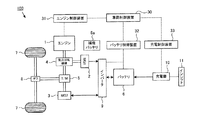
図1から図11は、実施例1を示す図である。図1は、本実施例の外部電源からの外部充電機能を備えたプラグインハイブリッド車両(Plug-in Hybrid Vehicle)の構成ブロック図である。図1に示すように、車両100は、エンジン1、第1MG(Motor Generator)2、第2MG3、動力分配機構4、トランスミッション(無段変速機、減速装置など)5、及びバッテリ6が搭載される。
Example 1
1 to 11 are diagrams showing a first embodiment. FIG. 1 is a configuration block diagram of a plug-in hybrid vehicle having an external charging function from an external power source according to the present embodiment. As shown in FIG. 1, a
エンジン1の出力軸は、動力分配機構4に接続される。動力分配機構4は、トランスミッション5の入力軸及び第1MG(発電用モータ)2の入力軸と連結される。トランスミッション5の出力軸は、車輪(駆動輪)7のディファレンシャルギア(差動装置)8に連結され、エンジン1の動力が動力分配機構4を介して車輪7に伝達される。また、トランスミッション5の出力軸は、第2MG(走行用モータ)3の出力軸と連結されている。第2MG3の動力は、トランスミッション5を介して車輪7に伝達されるようになっている。
An output shaft of the engine 1 is connected to the power distribution mechanism 4. The power distribution mechanism 4 is connected to the input shaft of the
動力分配機構4は、エンジン1が発生させる動力を2つの経路に分割し、トランスミッション5を介して車輪7に伝達する第1経路と、エンジン1が発生された動力を第1MG2に伝達して発電させる第2経路とを含む。動力分配機構4は、後述する車両制御装置30によって制御され、車両制御装置30は、エンジン1の駆動力を用いた走行制御やバッテリ6への充放電制御に応じて、第1経路及び第2経路それぞれに伝達される動力やその比率を制御する。
The power distribution mechanism 4 divides the power generated by the engine 1 into two paths, and transmits the power generated by the engine 1 to the first MG 2 by transmitting the power generated by the engine 1 to the first path MG 2 through the
バッテリ6は、第2MG3に電力を供給する電源装置である。バッテリ6の直流電力は、インバータ9により交流電力に変換され、第2MG3に供給される。第2MG3は、三相同期モータや三相誘導モータなどの交流モータである。
The
インバータ9は、バッテリ6から出力された直流電力を交流電力に変換し、交流電力を第2MG3に出力する。第2MG3は、インバータ9から出力された交流電力を受けて、車両100を走行させるための運動エネルギを生成する。第2MG3によって生成された運動エネルギは、トランスミッション5を介して車輪7に伝達される。
車両が減速したり、停止するときなどの車両100の制動時には、車輪7がトランスミッション5を介して第2MG3を駆動させる。第2MG3は、ジェネレータ(発電機)として作動し、車両100の制動時に発生する運動エネルギを電気エネルギ(交流電力)に変換する。
When the
本実施例の第2MG3は、バッテリ6から供給される電力によって駆動する車両走行の駆動源であるとともに、制動エネルギを電力に変換する回生ブレーキとして作動する。第2MG3によって発電された電力(回生エネルギ)は、インバータ9を介してバッテリ6に蓄えられる。インバータ9は、第2MG3が生成した交流電力を直流電力に変換し、直流電力(回生電力)をバッテリ6に出力する。
The
第1MG2は、エンジン1の動力により回転駆動することにより発電し、インバータ9を介して発電した電力をバッテリ6に供給するジェネレータである。第1MG2は、第2MG3と同様に、三相同期モータや三相誘導モータなどの交流モータで構成できる。
The first MG 2 is a generator that generates electric power by being rotationally driven by the power of the engine 1 and supplies electric power generated through the
第1MG2により発電された電力は、そのまま第2MG3を駆動させる電力として供給したり、バッテリ6に蓄えられる電力として供給することができる。例えば、第1MG2は、バッテリ6のSOC(State of Charge)や車両100の要求出力等に応じて制御され、第2MG3は、バッテリ6に蓄えられた電力及び第1MG2により発電された電力のうちのいずれか一方又は両方の電力によって駆動制御される。
The electric power generated by the first MG 2 can be supplied as it is as electric power for driving the
エンジン1は、ガソリンエンジンやディーゼルエンジンなどの燃料を燃焼させて動力を出力する公知の内燃機関である。エンジン1には、エンジン1の不図示の回転数センサを設けることができ、検出されたエンジン1の回転数(又は回転数を示す信号)を、エンジン制御装置31に出力することができる。
The engine 1 is a known internal combustion engine that outputs power by burning fuel such as a gasoline engine or a diesel engine. The engine 1 can be provided with a rotation speed sensor (not shown) of the engine 1, and the detected rotation speed (or signal indicating the rotation speed) of the engine 1 can be output to the
エンジン制御装置31は、車両制御装置30からのエンジン制御信号に基づいてエンジン1を制御するエンジンECUである。エンジン制御装置31は、車両全体の制御を行うメインコントローラである車両制御装置30に接続されている。エンジン制御装置31は、回転数センサなどの各種センサの検出値に基づいて、車両制御装置30によって定められた目標回転数及び目標トルクで動作するように、エンジン1の燃料噴射量や吸気する空気量、点火時期などを制御する。
The
バッテリ制御装置32(本発明の第2コントローラに相当する)は、バッテリ6のSOCや劣化状態などを管理するとともに、バッテリ6の充放電動作を車両制御装置30からのバッテリ制御信号に基づいて制御するバッテリECUである。
The battery control device 32 (corresponding to the second controller of the present invention) manages the SOC and the deterioration state of the
本実施例の車両100は、外部電源EPから供給される電力をバッテリ6に充電する外部充電手段を備える。車両100の側部には、インレット11が設けられる。インレット11は、車両100と外部電源EPとを連結する接続プラグを有する充電ケーブルが接続される接続口である。外部電源EPは、家庭用電源(商用電源)や充電スタンドなどがある。
The
充電制御装置33(本発明のコントローラに相当する)は、外部充電制御を遂行するECUであり、外部電源EPから延設される接続プラグがインレット11に接続されたことを検出すると(インレット11又は接続プラグから出力される接続プラグとインレット11とが接続状態であることを示す信号を受信すると)、インレット11とバッテリ6との間に設けられた充電器10を制御して外部電源EPから供給される電力を、バッテリ6に充電させる。
The charge control device 33 (corresponding to the controller of the present invention) is an ECU that performs external charge control, and detects that a connection plug extending from the external power source EP is connected to the inlet 11 (
充電器10は、インレット11とバッテリ6との間に接続され、外部電源EPから供給される交流電力を直流電力に変換するAC/DC変換器を含んで構成される。充電器10は、充電制御装置33から出力される駆動信号に基づいて動作する。
The
補機バッテリ6aは、例えば、車両100に搭載された車室空調装置(エアコンのインバータやモータ等)、AV機器、照明装置等に電力を供給する電源装置である。補機バッテリ6aは、バッテリ6よりも低電圧の電源装置であり、バッテリ6から電力供給を受けて充電することができる。この場合、補機バッテリ6aとバッテリ6との間に、不図示のDC/DCコンバータが接続され、高電圧のバッテリ6の電力を低電圧に降圧して補機バッテリ6aに充電することもできる。また、第1MG1によって発電された電力を充電することもできる。
The
車両全体の制御を行うメインコントローラである車両制御装置30は、車両100全体で要求される車両要求出力、例えば、アクセルペダルの踏み込み量に基づいて要求駆動力を算出し、算出された車両要求出力に応じてエンジン制御装置31を介したエンジン1の出力制御及びバッテリ制御装置32を介したバッテリ6の入出力制御を行う。
The
車両制御装置30は、運転状態に応じて駆動供給源を選択し、エンジン1及び第2MG3のうちの一方又は両方からの駆動力を用いた車両の走行制御を遂行する。例えば、アクセル開度が小さい場合や車速が低い場合などには、エンジン1からの駆動力を使用せずに(エンジン1を停止した状態で)、第2MG3のみを駆動源として車両100の走行制御を行う。なお、第2MG3のみを駆動源として車両100の走行制御の場合でも、エンジン1を駆動して第1MG2による発電制御を行うことができる。
The
一方、アクセル開度が大きい場合や車速が高い場合、又はバッテリ6のSOCが小さい場合などには、エンジン1を駆動源として用いた走行制御を遂行する。このとき、車両制御装置30は、エンジン1のみ、もしくはエンジン1および第2MG3の両方を駆動源として車両100の走行制御を行うことができる。
On the other hand, when the accelerator opening is large, when the vehicle speed is high, or when the SOC of the
なお、充電制御装置33以外の車両制御装置30、エンジン制御装置31、及びバッテリ制御装置32の各制御装置は、1つの制御装置で構成することも可能であり、メインコントローラとしての車両制御装置30が、各制御装置31、32の各機能を備えるように構成してもよい。
Note that each of the control devices of the
次に、本実施例の車両制御装置30及び車両100の車両走行制御について詳細に説明する。車両制御装置30は、バッテリ6のSOCが所定値に低下するまでバッテリ6に蓄えられた電力を積極的に使用して走行する第1走行モード(CD(Charge Depleting)モード)と、所定値のSOCを制御中心としてバッテリ6の充放電を行いながら走行する第2走行モード(CS(Charge Sustaining)モード)の一方を選択し、選択された走行モードに基づいて車両の走行制御を遂行することができる。なお、CSモードとCDモードとは、手動で切替えるように構成することも可能である。
Next, vehicle travel control of the
CDモードとCSモードとは、予め設定されたバッテリ6のSOC閾値(閾値TH)に基づいて区分することができ、SOCが閾値THよりも大きい領域ではCDモードでの車両走行が許容され、SOCが閾値THよりも小さい領域ではCDモードでの車両走行が許容されずに、CDモードでの車両走行が許容される。車両制御装置30は、バッテリ6のSOCに基づいてCDモード又はCSモードを選択することができ、イグニッションスイッチがONされて車両制御装置30が起動された際、バッテリ6のSOCが閾値TH以上であるか否かを判別し、閾値TH以上である場合にCDモードを選択する。一方、閾値TH未満である場合、CSモードを選択する。
The CD mode and the CS mode can be classified based on a preset SOC threshold value (threshold value TH) of the
CDモードは、バッテリ6に蓄えられた電力を維持せずに、主に第2MG3の駆動力のみで車両100を走行させる走行モードである。CDモードは、基本的にエンジン1を停止して、第2MG3の駆動力のみで車両出力全体を確保するように、エンジン1及び第2MG3を制御する。
The CD mode is a travel mode in which the
バッテリ6に蓄えられた電力を積極的に使用して車両100の走行制御を行うCDモードでは、バッテリ6のSOCが車両走行による電力消費に応じて低下する。つまり、CDモードは、閾値THよりも高い状態から、車両走行による電力消費に伴ってバッテリ6のSOCを低下させながらSOCが閾値THとなるまでバッテリ6の充放電を行い、バッテリ6に蓄えられた電力を積極的に使用して主に走行用モータを用いて車両100の走行制御を行う走行モードである。なお、CDモードでもアクセル開度が高い場合や車速が高い場合などには、駆動力を補うためにエンジン1の出力も使用した車両走行制御を行うことができる。
In the CD mode in which the travel control of the
CSモードは、バッテリ6に蓄えられた電力(SOC)を所定の目標値よりも低くならないように、エンジン1の駆動力又は/及び第2MG3の駆動力(バッテリ6の電力)を用いた車両制御を行う走行モードである。すなわち、SOCが目標値よりも低下すると、エンジン1を始動して第1MG2による充電制御が行われ、目標値よりも低いSOCを目標値に近づけるように上昇させつつ、エンジン1の駆動力又は/及び第2MG3の駆動力(バッテリ6の電力)を用いて走行制御を遂行する。CSモードは、所定の目標値をバッテリ6のSOC制御中心としてバッテリ6の充放電を行いながらエンジン1の駆動力又は/及び第2MG3の駆動力を用いて走行制御を行う走行モードである。
In the CS mode, vehicle control using the driving force of the engine 1 and / or the driving force of the second MG 3 (the power of the battery 6) so that the electric power (SOC) stored in the
図2は、本実施例のCDモード及びCSモードの車両走行制御の説明図である。縦軸はバッテリ6のSOC、横軸は時間である。
FIG. 2 is an explanatory diagram of the vehicle travel control in the CD mode and the CS mode of the present embodiment. The vertical axis represents the SOC of the
車両制御装置30は、例えば、イグニッションスイッチがONされて車両走行制御を開始する際(起動時)のバッテリ6のSOCが、閾値THよりも大きいか否かを判別する。図2の例では、バッテリ6のSOCが閾値THよりも大きいと判別され、CDモードを選択して車両走行制御を開始している。バッテリ6のSOCが閾値THよりも大きく、CDモードでの車両走行制御を開始する例としては、外部電源EPによる外部充電後の車両走行がある。
For example, the
車両制御装置30は、バッテリ制御装置32に車両出力に応じたバッテリ6の放電制御信号を出力し、バッテリ制御装置32は、バッテリ6から第2MG3に、蓄えられた電力を供給する(放電する)。CDモードが選択された走行制御では、バッテリ6のSOCが時間の経過とともに減少する。
The
車両制御装置30は、バッテリ制御装置32を介してバッテリ6のSOCを監視し、SOCが所定値(例えば、閾値TH)以下となったか否かを判別する。バッテリ6のSOCが閾値TH以下となった場合、CDモードからCSモードに切り替える(CSモードを選択する)。
The
車両制御装置30は、CSモードが選択されると、バッテリ6のSOCを所定の目標値(例えば閾値TH)を制御中心として、バッテリ6のSOCが目標値よりも低く(又は高く)ならないように、エンジン1の駆動力又は/及び第2MG3の駆動力(バッテリ6の電力)を用いた走行制御を行う。
When the CS mode is selected, the
ここで、閾値THは、バッテリ6に蓄えられているSOC(現在SOC)からCDモードでの車両走行制御におけるSOCの下限値であり、CDモードからCSモードへ移行する閾値である。なお、閾値THは、エンジン1のみを駆動源として車両走行制御を行うための閾値ではなく、バッテリ6のSOCが目標値よりも低くならないようにエンジン1又は/及び第2MG3を駆動源として用いた車両走行制御を行う際の閾値である。また、図2の例では、CDモードのSOC下限値とCSモードのSOC制御中心(目標値)とが同じ閾値THである場合を一例に説明しているが、これに限らず、個別の値に設定することも可能である。例えば、CDモードでの車両走行制御におけるSOCの下限値に対応する第1閾値を設定し、第1閾値までバッテリ6のSOCが低下した後は、第1閾値とは異なる第2閾値に設定された目標値をSOC制御中心として、エンジン1の駆動力又は/及び第2MG3の駆動力(バッテリ6の電力)を用いた走行制御を行うことができる。
Here, the threshold value TH is a lower limit value of the SOC in the vehicle travel control in the CD mode from the SOC (current SOC) stored in the
次に、図3を参照して、本実施例のプラグインハイブリッド車両100に搭載される電池システムについて説明する。本実施例の電池システムは、バッテリ6の直流電力をインバータ9を介して第2MG3に供給したり、車両制動時の回生エネルギをバッテリ6に充電する充放電系と、エンジン1及びバッテリ6の温度調節装置を備え、外部電源EPからの電力をバッテリ6の充電させる外部充電系と、を含んで構成されている。
Next, a battery system mounted on the plug-in
図3に示すように、バッテリ6は、電気的に直列に接続された複数の単電池61を有した組電池である。単電池61としては、ニッケル水素電池やリチウムイオン電池といった二次電池を用いることができる。また、二次電池の代わりに、電気二重層キャパシタ(コンデンサ)を用いることもできる。
As shown in FIG. 3, the
複数の単電池61(蓄電素子)は、バスバーによって電気的に直列に接続され、バッテリ6を構成している。なお、電気的に並列に接続された複数の単電池61群を直列に複数接続してバッテリ6を構成することもできる。また、バッテリ6を構成する単電池61の数は、車両100の要求出力等によって任意に決定することができる。
The plurality of single cells 61 (electric storage elements) are electrically connected in series by a bus bar to constitute the
本実施例の電池システムは、バッテリ6とインバータ9との間に、DC/DCコンバータ201(昇圧回路)が接続されており、バッテリ6と接続されるDC/DCコンバータ201が、インバータ9に接続されている。DC/DCコンバータ201は、バッテリ6の出力電圧を昇圧してインバータ9に出力することができる。また、DC/DCコンバータ201は、インバータ9からバッテリ6への出力電圧を降圧することができる。
In the battery system of the present embodiment, a DC / DC converter 201 (boost circuit) is connected between the
バッテリ6の正極端子に接続される正極ラインPL及びバッテリ6の負極端子に接続される負極ラインNLには、システムメインリレーSMR−B,SMR−Gがそれぞれ設けられている。システムメインリレーSMR−B,SMR−Gは、車両制御装置30からの制御信号を受けることにより、オンおよびオフの間で切り替わる。システムメインリレーSMR−Gには、システムメインリレーSMR−Pおよび電流制限抵抗Rが並列に接続され、システムメインリレーSMR−Pおよび電流制限抵抗Rは、直列に接続されている。
System main relays SMR-B and SMR-G are provided on the positive line PL connected to the positive terminal of the
システムメインリレーSMR−B,SMR−Gは、バッテリ6とDC/DCコンバータ(インバータ9)との電気的な接続を許容する。バッテリ6をDC/DCコンバータ201と接続するとき、車両制御装置30は、まず、システムメインリレーSMR−Bをオフからオンに切り替えるとともに、システムメインリレーSMR−Pをオフからオンに切り替える。これにより、電流制限抵抗Rに電流が流れ、バッテリ6をインバータ9に接続するときに流れる突入電流を抑制することができる。
System main relays SMR-B and SMR-G allow electrical connection between
車両制御装置30は、システムメインリレーSMR−Gをオフからオンに切り替えた後に、システムメインリレーSMR−Pをオンからオフに切り替える。これにより、バッテリ6およびDC/DCコンバータ201の接続が完了し、図1に示す電池システムは、起動状態(Ready−On)となる。車両制御装置30には、車両のイグニッションスイッチのオン/オフ(IG−ON/IG−OFF)に関する情報が入力され、車両制御装置30は、イグニッションスイッチがオフからオンに切り替わることに応じて、電池システムを起動する。
The
一方、イグニッションスイッチがオンからオフに切り替わったとき、車両制御装置30は、システムメインリレーSMR−B,SMR−Gをオンからオフに切り替える。これにより、バッテリ6およびDC/DCコンバータ201(インバータ9)の接続が遮断され、電池システムは、停止状態(Ready−Off)となる。
On the other hand, when the ignition switch is switched from on to off, the
監視ユニット20は、バッテリ6の端子間電圧を検出したり、各単電池61の電圧を検出する。監視ユニット20は、検出結果をバッテリ制御装置32(車両制御装置30)に出力する。監視ユニット20は、複数の単電池61に対し、各単電池の電圧値それぞれを検出したり、直列に接続された所定数の単電池61群を1ブロックとして電圧を検出することができる。1ブロックに含まれる単電池61の数は、任意に設定することができる。
The monitoring unit 20 detects the voltage between the terminals of the
電流センサ21は、バッテリ6に流れる電流を検出し、検出結果をバッテリ制御装置32(車両制御装置30)に出力する。本実施例では、バッテリ6の正極端子と接続された正極ラインPLに電流センサ21を設けている。なお、電流センサ21は、バッテリ6に流れる電流を検出できればよく、電流センサ21を設ける位置は適宜設定することができる。例えば、バッテリ6の負極端子と接続された負極ラインNLに電流センサ21を設けることができる。なお、複数の電流センサ21を用いることもできる。
温度センサ22は、バッテリ6の温度(電池温度)を検出する。温度センサ22は、検出結果をバッテリ制御装置32(車両制御装置30)に出力する。温度センサ22は、バッテリ6の一箇所に設けることもできるし、バッテリ6のうち、互いに異なる複数の箇所に設けることもできる。複数のバッテリ6の検出温度を用いる場合、バッテリ6の温度は、複数の検出温度のうちの最小値、最大値や複数の検出温度の中央値や平均値などを適宜用いることができる。
The
バッテリ制御装置32は、図3に示すように、メモリ32aを備えることができる。メモリ32aは、監視ユニット20、電流センサ21及び温度センサ22の各検出値や、各検出値を用いて算出されるSOCや満充電容量等の算出値、充放電制御に用いられる各種情報等を記憶している。なお、メモリ32aは、バッテリ制御装置32に対して外部接続される個別の記憶領域として構成することもできる。つまり、メモリ32aは、バッテリ制御装置32に対して内蔵又は外付けされる構成とすることができる。
The
バッテリ制御装置32は、監視ユニット20によって検出された電圧値、電流センサ21によって検出された電流値、温度センサ22によって検出された電池温度に基づいて、バッテリ6のSOCを算出(推定)し、算出されたSOC及び満充電容量推定値に基づいて、バッテリ6の充放電制御を行うことができる。バッテリ制御装置32は、SOC推定部や満充電容量演算部などの各機能が含まれるように構成することができる。
The
バッテリ6のSOCは、バッテリ6の満充電容量に対して現在の充電容量の割合(充電状態)を示すものであり、満充電容量はSOCの上限値である。SOCは、バッテリ6の開放電圧(OCV:Open Circuit Voltage)から特定することができる。例えば、バッテリ6のOCVとSOCとの対応関係をOCV−SOCマップとして予めメモリ32aに記憶しておく。バッテリ6は、監視ユニット20によって検出される電圧(CCV:Closed Circuit Voltage)からバッテリ6のOCVを算出し、OCV−SOCマップからSOCを算出することができる。
The SOC of the
なお、バッテリ6のOCVとSOCの対応関係は、電池温度に応じて変化するので、OCV−SOCマップを電池温度毎にメモリ32aに記憶させておき、バッテリ6のOCVからSOCを推定する際の電池温度に応じてSOC−OCVマップを切り換えて(選択して)、バッテリ6のSOCを推定するようにしてもよい。
Since the correspondence between the OCV and the SOC of the
したがって、バッテリ制御装置32は、充放電中の監視ユニット20によって検出された電圧値(CCV)を監視することにより、バッテリ6の過充電状態や過放電状態を把握することができる。例えば、算出されたSOCが満充電容量に対する所定の上限SOCよりも高くならないようにバッテリ6の充電を制限したり、下限SOCよりも低くならないように放電を制限する充放電制御を行うことができる。
Therefore, the
なお、バッテリ制御装置32は、DC/DCコンバータ201、インバータ9および第2MG3毎に設けることも可能であり、複数の制御装置から構成される1つコントロールユニットとして構成することもできる。
The
このようにバッテリ6、DC/DCコンバータ201、インバータ9及びバッテリ制御装置32は、車両走行用の電力を供給する高電圧の充放電系電池システムを構成している。
Thus, the
次に、外部電源EPからの電力をバッテリ6の充電させる外部充電系電池システムについて説明する。外部充電系は、充放電系の駆動及び制御が停止している状態であっても、充放電系と独立して起動及び制御される。外部充電系は、外部電源から供給される電力をバッテリ6の充電する外部充電と、エンジン1及びバッテリ6の温度調節装置を用いた温度調節とを行う。
Next, an external charging system battery system that charges the
充電器10は、バッテリ6の正極端子及びシステムメインリレーSMR−Bを接続する正極ラインPLと、バッテリ6の負極端子及びシステムメインリレーSMR−Gを接続する負極ラインNLとに接続されている。
The
充電器10および正極ラインPL,負極ラインNLを接続する各ラインPL1,NL1には、充電リレーRch1,Rch2がそれぞれ設けられている。充電リレーRch1,Rch2は、充電制御装置33からの制御信号を受けることにより、オンおよびオフの間で切り替わる。
Charging relays Rch1 and Rch2 are provided in the lines PL1 and NL1 connecting the
充電器10には、充電DC/DCコンバータ202(本発明のDC/DCコンバータに相当する)が接続されている。充電DC/DCコンバータ202は、バッテリヒータ303及びエンジンヒータ304の双方に接続されており、充電器10から出力される外部電源から供給される電力を昇圧してバッテリヒータ303及びエンジンヒータ304それぞれに出力する。
The
バッテリヒータ303は、バッテリ6を昇温させる加熱装置であり、外部電源EPから供給される外部電力の電力によって駆動する。また、エンジンヒータ304は、エンジン1を昇温させる加熱装置であり、外部電源EPから供給される外部電力の電力によって駆動する。
The
バッテリヒータ303としては、例えば、電気エネルギを熱エネルギに変換する電気ヒータを用いることができる。バッテリヒータ303は、バッテリ6に対して直接接触させて設けたり、部材が空間を介して間接的に設けることができる。また、複数の電気ヒータで1つのバッテリヒータ303を構成することができ、バッテリ6の複数個所に加熱部が設けられるように構成することもできる。
As the
エンジンヒータ304としては、例えば、電気エネルギを熱エネルギに変換するブロックヒータを用いることができる。ブロックヒータは、エンジン1を冷却する冷却液の循環経路に設けることができる。エンジンヒータ304によりエンジン冷却液を加熱することで、エンジン1を加熱する。エンジンヒータ304は、エンジン冷却液の循環経路の複数個所に設けることができ、複数のブロックヒータで構成することもできる。
As the
充電器10は、外部電源EPから供給される外部電力を、バッテリ6に供給する第1電力供給と、バッテリヒータ303及びエンジンヒータ304に供給する第2電力供給を行う。充電器10は、充電制御装置33の制御信号によって動作し、第1電力供給と第2電力供給とを並行して同時に行ったり、第1電力供給終了後に第2電力供給を開始したりすることができる。
The
充電DC/DCコンバータ202とバッテリヒータ303とを接続する電力供給ラインには、スイッチRh1が設けられている。また、充電DC/DCコンバータ202とエンジンヒータ304とを接続する電力供給ラインには、スイッチRh2が設けられている。スイッチRh1,Rh2は、充電制御装置33によってオン/オフの切り換え制御が行われる。
A switch Rh <b> 1 is provided in the power supply line connecting the charging DC /
スイッチRh1,Rh2がオンされると、充電DC/DCコンバータ202とバッテリヒータ303とが接続され、充電DC/DCコンバータ202とエンジンヒータ304とが接続される。バッテリヒータ303及びエンジンヒータ304は、共通する1つの充電DC/DCコンバータ202に接続され、充電器10の第2電力供給によって出力された電力を受けて動作する。
When switches Rh1 and Rh2 are turned on, charging DC /
充電DC/DCコンバータ202から各ヒータ303,304への電力供給(第2電力供給)は、同時に又は異なるタイミングで行うことができる。例えば、スイッチRh1,Rh2を同時にオンしてバッテリヒータ303及びエンジンヒータ304の双方に電力を供給したり、スイッチRh1,Rh2の一方のみをオンにして一方のヒータへの通電を行った後に、他方のみをオンにして他方のヒータへの通電を行うこともできる。スイッチRh1,Rh2のオン/オフのタイミング(ヒータへの電力供給タイミング)は、任意に設定することができる。
Power supply (second power supply) from the charging DC /
また、バッテリヒータ303は、ヒータ制御装置301が接続されている。ヒータ制御装置301は、バッテリヒータ303に設けられるサーミスタ(温度センサ)やサーモスタットを制御し、サーミスタによって検出されたバッテリヒータ303の温度が設定された温度の付近に維持されるように制御する。例えば、バッテリヒータ303が設定温度(目標温度)に達した場合に充電DC/DCコンバータ202からの通電を遮断し、設定温度よりも低くなった場合に通電を再開して、バッテリヒータ303の温度が一定の温度を維持するように、バッテリヒータ303への通電/非通電を制御することができる。
The
外気温センサ302は、車両100の外気温を検出する温度センサであり、検出結果を充電制御装置33に出力する。また、充電制御装置33は、監視ユニット20、電流センサ21及び温度センサ22,23からの各検出値が入力される。
The outside
温度センサ23は、エンジン1の温度(エンジン冷却液の温度)を検出する。温度センサ23は、検出結果を充電制御装置33に出力する。温度センサ23は、バッテリ6の電池温度を検出する温度センサ22と同様の構成とすることができる。
The
このように充電器10、充電DC/DCコンバータ202、バッテリヒータ303、エンジンヒータ304、充電制御装置33、及びヒータ制御装置301は、外部電源EPから供給される電力をバッテリ6に充電させ、かつエンジン1及びバッテリ6を昇温させる外部充電系電池システムを構成している。
Thus, the
図4は、本実施例のエンジン1及びバッテリ6の温度調節制御を含む外部充電制御の処理フローを示す図である。充電制御装置33は、外部電源EPから供給される電力をバッテリ6に充電させる外部充電制御と、外部充電制御が終了するまでの間に外部電源EPから供給される電力を充電DC/DCコンバータ202を介してバッテリヒータ303及びエンジンヒータ304に供給し、エンジン1及びバッテリ6を昇温させる温度調節制御と、を行う。
FIG. 4 is a diagram showing a processing flow of external charge control including temperature adjustment control of the engine 1 and the
本実施例の外部充電制御は、外部電源EPと接続される充電プラグが、インレット11に接続されたことをトリガーに開始する即時充電と、予め設定された充電開始時間(充電終了時間のみが設定され、充電終了時間と現在時刻から算出される充電開始時間を含む)に充電を開始するタイマー充電と、を含むことができる。
In the external charging control of this embodiment, the charging plug connected to the external power source EP is triggered by the fact that the charging plug is connected to the
充電制御装置33は、図4の例のように、外部電源EPと接続される充電プラグが、インレット11に接続されたことをトリガーに、充電制御装置33が起動して外部充電を開始することができる。つまり、充電プラグがインレット11に接続されると(S101)、インレット11から充電制御装置33に充電プラグ接続信号が出力される。充電制御装置33は、充電プラグ接続信号の受信をトリガーに通電されて停止状態から起動状態に遷移することができる(S102)。
As shown in the example of FIG. 4, the charging
また、充電制御装置33は、不図示のタイマーによって予め設定された充電開始時間に通電されて停止状態から起動状態に遷移し、外部電源EPと接続される充電プラグがインレット11に接続されたか否かを確認した後に、外部充電を開始することができる。
In addition, the charging
充電制御装置33は、充電リレーRch1,Rch2をオフからオンに切り換えて充電器10とバッテリ6とを接続する。このとき、充電制御装置33の起動に伴って、充電器10や充電DC/DCコンバータ202、ヒータ制御装置301などの外部充電系の電池システムは、通電によって起動されて動作可能な状態となっている。一方、充放電系のDC/DCコンバータ201及びバッテリ制御装置32は、通電されずに起動されていない状態(停止状態)となっている。また、充放電系のシステムメインリレーSMR−B,SMR−Gもオフであり、バッテリ6とDC/DCコンバータ(インバータ9)との電気的に遮断されている。
The charging
充電制御装置33は、充電器10を制御して外部電源EPから供給される外部電力を一定の電流でバッテリ6に充電させる(S103)。また、充電制御装置33は、エンジン1及びバッテリ6の温度調節制御を行う(S104)。
The charging
充電制御装置33は、監視ユニット20によって検出されるバッテリ6の電圧値を監視し、充電終了に応じた所定のSOC上限値に対応する電圧値となったときに(S105)、外部電源EPからバッテリ6への電力供給を終了し(S105のYES)、充電を終了させる(S106)。タイマー充電の場合、充電制御装置33は、充電終了時刻になった場合にバッテリ6のSOCが所定のSOC上限値になったか否かにかかわらず、充電を終了することができる。充電終了時刻前にSOC上限値に達している場合には、充電器10からバッテリ6への外部電力の供給を停止し、充電終了時刻になったときに、充電を終了することができる。
The charging
また、充電制御装置33は、外部充電制御の終了に伴ってエンジン1の温度調節制御とバッテリ6の温度調節制御も終了させることができる。本実施例の温度調節は、外部電源から充電器10に出力される外部電力を使用してバッテリヒータ303及びエンジンヒータ304を動作させているためである。なお、バッテリ6に充電電力が供給されていない状態でも外部電源から充電器10に出力される外部電力を使用してバッテリヒータ303及びエンジンヒータ304を動作させる温度調節制御を行うことができる。つまり、外部電源EPの外部電力を供給可能な状態であれば、バッテリ6への充電電力の供給有無にかかわらず、外部充電終了前であるとして、温度調節制御を行うことができる。
Further, the charging
図5Aは、図4に示したステップS104のバッテリ6の温度調節制御の詳細フローを示す図である。図5Aに示すように、充電制御装置33は、温度センサ22からバッテリ6の電池温度T2を取得する(S201)。充電制御装置33は、電池温度T2が所定の温度Eよりも低いか否かを判別し(S202)、電池温度T2が温度Eよりも低い場合、スイッチRh1をオフからオンに切り換えて充電DC/DCコンバータ202とバッテリヒータ303を接続し、バッテリヒータ303をオンにする(S203)。
FIG. 5A is a diagram showing a detailed flow of temperature adjustment control of the
充電制御装置33は、電池温度T2が所定の温度Eよりも高いか否かを判別し(S204)、電池温度T2が温度Eよりも高い場合、スイッチRh1をオンからオフに切り換えて充電DC/DCコンバータ202とバッテリヒータ303との接続を遮断し、バッテリヒータ303をオフにする(S205)。このとき、充電制御装置33は、外部充電制御が終了するまでの間、図5Aに示したステップS201からS205の各ステップを繰り返し行うことができことができる(図4のステップS105のNO)。外部充電制御の終了に伴って、バッテリヒータ303の温度調節制御(充電DC/DCコンバータ202を介した電力供給制御)を終了する(図4のステップS105のYES)。
The
温度Eは、バッテリ6の加熱目標温度であり、電池温度に依存するバッテリ6の出力特定に応じて予め設定された値である。バッテリ6の出力特性は、温度が低いほど、内部抵抗が高くなるため、出力が低下する。実験や実測値等から得られた電池温度と出力の関係を予め取得しておき、外部充電後の車両走行において必要なバッテリ6の出力に応じて最適な値を温度Eとして設定することができる。
The temperature E is the heating target temperature of the
図5Bは、図4に示したステップS104のエンジン1の温度調節制御の詳細フローを示す図である。充電制御装置33は、温度センサ23からエンジン1のエンジン温度(エンジン冷却液の温度)T3を取得する(S301)。充電制御装置33は、エンジン温度T3が所定の温度Aよりも低いか否かを判別し(S302)、エンジン温度T3が温度Aよりも低い場合、スイッチRh2をオフからオンに切り換えて充電DC/DCコンバータ202とエンジンヒータ304を接続し、エンジンヒータ304をオンにする(S303)。
FIG. 5B is a diagram showing a detailed flow of temperature adjustment control of engine 1 in step S104 shown in FIG. The
充電制御装置33は、エンジン温度T3が目標温度Dよりも高いか否かを判別し(S304)、エンジン温度T3が目標温度Dよりも高い場合、スイッチRh2をオンからオフに切り換えて充電DC/DCコンバータ202とエンジンヒータ304との接続を遮断し、エンジンヒータ304をオフにする(S305)。温度Aは、エンジン1の加熱目標温度である。このときも、充電制御装置33は、外部充電制御が終了するまでの間、図5Bに示したステップS301からS305の各ステップを繰り返し行うことができる(図4のステップS105のNO)。外部充電制御の終了に伴って、エンジンヒータ304の温度調節制御(充電DC/DCコンバータ202を介した電力供給制御)を終了する(図4のステップS105のYES)。
The
バッテリヒータ303によるバッテリ6の温度調節と、エンジンヒータ304によるエンジン1の温度調節の各処理は、同時並行で又は個別のタイミングで行うことができる。また、充電開始から終了するまでの間、温度調節制御は、バッテリ6の目標温度及びエンジン1の目標温度それぞれを維持するように、任意のタイミングでバッテリヒータ303又は/及びエンジンヒータ304のオン又はオフにする制御を行うことができる。
Each process of the temperature adjustment of the
図6は、本実施例のエンジン昇温がある場合の外部充電によるエンジン温度の温度推移と外部充電後の車両走行におけるエンジン温度の温度推移とを示す図である。図7は、本実施例のエンジン昇温がない場合の外部充電によるエンジン温度の温度推移と外部充電後の車両走行におけるエンジン温度の温度推移とを示す図である。 FIG. 6 is a diagram illustrating a temperature transition of the engine temperature due to external charging and a temperature transition of the engine temperature during traveling of the vehicle after the external charging when the engine temperature rises according to the present embodiment. FIG. 7 is a diagram illustrating a temperature transition of the engine temperature due to external charging and a temperature transition of the engine temperature during vehicle travel after external charging when there is no engine temperature increase in the present embodiment.
車両制御装置30は、エンジン1の温度が閾値Teを下回ると、エンジン1を強制駆動(強制始動)して、暖気運転を行う。図6に示すように、時刻t1の充電開始時刻において、エンジン1の温度は、閾値Teよりも低い温度となっているが、外部充電中の温度調節制御によって、充電終了時刻の時刻t2において、エンジン1の温度は、閾値Teを上回る温度まで上昇している。
When the temperature of the engine 1 falls below the threshold Te, the
外部充電が終了した後の時刻t3において車両100のイグニッションスイッチがオンされ(IG−ON)、時刻t4から車両走行が開始される場合、車両制御装置30は、エンジン1の温度が、閾値Teを上回っているので、CDモードでの車両走行制御を行う。時刻t4以降のCDモードでの車両走行中、エンジン1は、駆動していない状態で走行風に晒されるので、時間が経過するにつれてエンジン1の温度は低下するが、車両走行開始時のエンジン1の温度が閾値Teよりも高い状態なので、エンジン1が強制駆動されることなく、CDモードでの車両走行を維持することができ、燃費が向上する。
When the ignition switch of the
したがって、図5に示したエンジンヒータ304によるエンジン1の加熱目標温度Dは、エンジン1が強制駆動される温度閾値Teよりも高く、かつ外部充電後の車両走行中の温度低下を考慮した値に設定することができる。また、温度Aは、例えば、エンジン1が強制駆動される温度閾値Teとすることができる。詳細については後述する。
Therefore, the heating target temperature D of the engine 1 by the
一方、図7に示すように、時刻t1から時刻t2までの外部充電期間中にエンジン1の温度調節制御を行わないと、充電終了時刻の時刻t2以降、エンジン1の温度は、閾値Teを下回った状態となる。 On the other hand, as shown in FIG. 7, if the temperature adjustment control of the engine 1 is not performed during the external charging period from the time t1 to the time t2, the temperature of the engine 1 falls below the threshold Te after the time t2 of the charging end time. It becomes a state.
外部充電が終了した後の時刻t3において車両100のイグニッションスイッチがオンされると(IG−ON)、車両制御装置30は、エンジン1の温度が、閾値Teを下回っているので、エンジン1を強制駆動するとともに、その後の時刻t4から車両走行が開始されても、エンジン1が駆動された状態での車両走行制御、例えば、CSモードでの車両走行制御を行う。この場合、外部充電によってSOCがCSモード閾値よりも高くても、CDモードでの車両走行制御を行うことができず、燃費が悪化してしまう。
When the ignition switch of the
このように、本実施例の電池システムは、外部充電後の車両走行が、主に第2MG3の駆動力のみで車両100を走行させてバッテリ6のSOCが所定値に低下するまでバッテリ6の電力を積極的に使用するCDモードとなるように、エンジン1の強制駆動が行われる温度閾値よりも高い温度に昇温させ、かつ外部充電後の車両走行において必要なバッテリ6の出力に応じた電池温度まで昇温させる外部充電系電池システムを備えている。
As described above, in the battery system of the present embodiment, the
そして、外部充電系電池システムでは、2つのバッテリヒータ303及びエンジンヒータ304への電力供給に対して共通する1つの充電DC/DCコンバータ202が動作し、かつバッテリ6の外部充電制御とバッテリヒータ303及びエンジンヒータ304への電力供給制御を含む温度調節制御とが1つの充電制御装置33によって遂行される。
In the external charging system battery system, one charging DC /
このため、外部充電時に動作する充電DC/DCコンバータ及び制御装置(コントローラ)の数が最小限に抑えられるので、例えば、外部充電時に充電DC/DCコンバータ及び制御装置を動作させるために必要な消費電力を低減することができる。また、充電DC/DCコンバータの電圧変換時の電力損失が、2つのバッテリヒータ303及びエンジンヒータ304それぞれにDC/DCコンバータを設ける場合に比べて低減され、外部電源EPからバッテリ6へ供給される電力量を電力損失分、増やすことができる。
For this reason, the number of charging DC / DC converters and control devices (controllers) that operate during external charging can be minimized. For example, consumption necessary for operating the charging DC / DC converter and control devices during external charging. Electric power can be reduced. Further, the power loss at the time of voltage conversion of the charging DC / DC converter is reduced as compared with the case where the DC / DC converter is provided in each of the two
したがって、充電DC/DCコンバータ及び制御装置を動作させるための消費電力損失と、外部充電時の電圧変換時の電力損失とが低減でき、外部電力をバッテリに充電させつつ、外部電力を使用して2つのバッテリヒータ303及びエンジンヒータ304を動作させてバッテリ6及びエンジン1を昇温させるために必要な外部電力量(外部充電コスト)を抑制させることができる。
Therefore, the power consumption loss for operating the charging DC / DC converter and the control device and the power loss at the time of voltage conversion at the time of external charging can be reduced, and the external power is used while charging the battery with the external power. The external electric energy (external charging cost) necessary for operating the two
また、本実施例の電池システムは、充電器10が、バッテリ6とシステムメインリレーSMR−B,SMR−Gとの間に接続されており、外部充電系の各機器が充放電系と独立したシステム構成となっている。このため、システムメインリレーSMR−B,SMR−Gがオフ状態であって充放電系のDC/DCコンバータ201及びバッテリ制御装置32が起動されていない状態で、外部充電制御及び温度調節制御を行うことができる。
Further, in the battery system of the present embodiment, the
したがって、充電器10及び充電DC/DCコンバータ202を含む外部充電系のみを起動して外部充電及びエンジン等の温度調節を行うことができる。バッテリ6から第2MG3に電力を供給する充放電系の消費電力を抑制でき、外部充電コストを抑制することができる。
Therefore, only the external charging system including the
特に、外部電源EPの電力をバッテリ6に充電する外部充電は、充電時間が短時間かつ低コストで行うことが好ましい。本実施例の電池システムは、外部充電を短時間で行う点を考慮して、バッテリ6に外部電力を充電するのと同時並行で、外部電源から供給される外部電力の一部を使用して2つのバッテリヒータ303及びエンジンヒータ304を動作させてバッテリ6及びエンジン1を昇温させることができる。
In particular, the external charging for charging the
上述したように、2つのバッテリヒータ303及びエンジンヒータ304によって消費される電力分、バッテリ6に充電される電力量が低くなるものの、外部充電時に動作する充電DC/DCコンバータ及び制御装置の数が最小限に抑えられるので、DC/DCコンバータ及び制御装置を動作させるための消費電力損失と、外部充電時の電圧変換時の電力損失とが低減される分、充電期間中により多くの外部電力をバッテリ6に充電させることができる。このため、外部充電コストを抑制することができる。
As described above, the amount of electric power consumed by the two
なお、外部電源EPが商用電源(AC100,AC200)などの低電圧系である場合、外部充電系は、充放電系よりも低電圧の電池システムとなるため、外部充電系の充電DC/DCコンバータ202は、充放電系のDC/DCコンバータ201よりも、入力電圧に対する出力電圧の電圧変換比を低くなる。例えば、バッテリ6に蓄えられた高電圧の電力をDC/DCコンバータ201で降圧してバッテリヒータ303及びエンジンヒータ304に出力する場合に比べ、電圧変換時の電力損失が低減される。
When the external power supply EP is a low voltage system such as a commercial power supply (AC100, AC200), the external charging system is a battery system having a lower voltage than the charging / discharging system. 202 has a lower voltage conversion ratio of the output voltage to the input voltage than the charge / discharge DC /
また、外部充電系の充電制御装置33や充電DC/DCコンバータ202は、補機バッテリ6aから供給される電力、又は外部電源EPから供給される電力によって駆動することができる。外部電源EPから供給される電力によって駆動される場合、外部充電時に動作する充電DC/DCコンバータ及び制御装置の数が最小限に抑えられるので、外部充電コストを抑制することができる。
The external charging system
一方、補機バッテリ6aから供給される電力によって駆動される場合であっても、外部充電コストを抑制することができる。つまり、補機バッテリ6aは、上述のように外部充電されるバッテリ6の電力を用いて充電されるので、補機バッテリ6aからの電力によって駆動する充電制御装置33や充電DC/DCコンバータ202の消費電力量は、バッテリ6の消費電力量となる。したがって、補機バッテリ6aで消費される電力が低減されれば、車両走行で使用される電力をバッテリ6により多く充電できることになり、補機バッテリ6aからの電力によって駆動する充電制御装置33や充電DC/DCコンバータ202が最小限に抑えられているので、外部充電コストを抑制することができる。
On the other hand, even if it is a case where it drives with the electric power supplied from the
次に、エンジン1の温度調節制御における目標温度の設定処理について詳細に説明する。図6の例で示したように、CDモードでの車両走行中、エンジン1は、駆動していない状態で走行風に晒されるので、時間が経過するにつれてエンジン1の温度は低下する。したがって、車両走行中の走行風よってエンジン1の温度が閾値Teよりも低くなると、エンジン1が強制駆動されてしまい、CDモードでの車両走行を維持することができない。 Next, the target temperature setting process in the temperature adjustment control of the engine 1 will be described in detail. As shown in the example of FIG. 6, while the vehicle is traveling in the CD mode, the engine 1 is exposed to the traveling wind without being driven, so that the temperature of the engine 1 decreases as time elapses. Therefore, if the temperature of the engine 1 becomes lower than the threshold Te due to the traveling wind during the traveling of the vehicle, the engine 1 is forcibly driven and the vehicle traveling in the CD mode cannot be maintained.
そこで、本実施例では、外部充電後の車両走行中の温度低下を考慮して、外部電源による充電終了後のCDモードでの車両走行において、車両走行が終了するまでにエンジン1の温度がエンジン1を強制駆動させる閾値Teを下回らないように、加熱目標温度Dを設定する。 Therefore, in the present embodiment, in consideration of the temperature decrease during vehicle travel after external charging, the temperature of the engine 1 is increased until the vehicle travel is completed in vehicle travel in the CD mode after the completion of charging by the external power source. The heating target temperature D is set so as not to fall below the threshold value Te for forcibly driving 1.
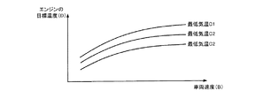
図8は、車両100の車速とエンジン1の加熱目標温度Dとの関係を示す図である。車両走行中のエンジン1の温度低下は、車速に応じた走行風によって異なる。本実施例では、エンジン1の加熱目標温度Dを、車速に応じた温度低下量に基づいて設定する。
FIG. 8 is a diagram showing the relationship between the vehicle speed of the
例えば、外部電源による充電終了後のCDモードでの車両走行は、外部電源による充電終了後のバッテリ6のSOCが、CSモード閾値に低下するまで継続することができる。このため、外部電源による充電終了後のバッテリ6のSOCとCSモード閾値のSOCとのSOC差に基づく電力を使用したCDモードでの車両走行が可能となる。そこで、外部電源による充電終了後の充電量に対応するCDモードでの車両走行が持続可能な走行距離(CDモード走行距離)に対し、車速に応じた温度低下量を予め把握しておけば、図8に示すような車両車速と加熱目標温度との関係を規定することができる。
For example, the vehicle traveling in the CD mode after the end of charging by the external power source can be continued until the SOC of the
図8に示すように、車両速度が高くなるにつれて加熱目標温度が高く設定され、車速が低くなるにつれて、加熱目標温度Dが低く設定される。言い換えれば、加熱目標温度Dは、車両速度が高くなるほど大きく低下する温度分を加算して大きな値に設定される。なお、車速に応じた温度低下量は、予め実験等で求めておくことができ、エンジン1が強制駆動される閾値Teに車速に応じた温度低下量を加算した値を、加熱目標温度Dとして図8の例のように予め規定することができる。 As shown in FIG. 8, the heating target temperature is set higher as the vehicle speed becomes higher, and the heating target temperature D is set lower as the vehicle speed becomes lower. In other words, the heating target temperature D is set to a large value by adding the temperature that greatly decreases as the vehicle speed increases. The temperature decrease amount according to the vehicle speed can be obtained in advance by experiments or the like, and a value obtained by adding the temperature decrease amount according to the vehicle speed to the threshold Te at which the engine 1 is forcibly driven is set as the heating target temperature D. It can be defined in advance as in the example of FIG.
車両100の速度に応じた加熱目標値Dは、例えば、CDモードでの車両走行制御において予め設定されている車両100の最高速度に応じて設定することができる。つまり、外部電源による充電終了後の充電量に対応するCDモードでの車両走行が持続可能な走行距離に対し、最高速度で車両走行を継続した場合のエンジン1の温度低下量を考慮して、加熱目標温度Dを設定することで、車両走行中にエンジン1が強制駆動されないようにすることができる。
The heating target value D corresponding to the speed of the
なお、加熱目標温度Dは、外気温の最低気温によって異なるように設定される。車両走行中の外気温が低い場合、車速に応じた温度低下量がより大きくなるためである。図8の例では、外気温の最低気温毎に、車速と加熱目標温度との対応関係が規定されている。 The heating target temperature D is set so as to vary depending on the lowest outside air temperature. This is because when the outside air temperature during vehicle travel is low, the amount of temperature decrease corresponding to the vehicle speed becomes larger. In the example of FIG. 8, the correspondence relationship between the vehicle speed and the heating target temperature is defined for each minimum outside temperature.
図9は、CDモードの車両走行制御における最高車速と最低気温とに応じたエンジンの目標温度設定処理を含むエンジン1の温度調節制御の処理フローを示すフローチャートである。図9の例は、図5Bに示したエンジン1の温度調節処理に対応している。 FIG. 9 is a flowchart showing a processing flow of temperature adjustment control of the engine 1 including engine target temperature setting processing according to the maximum vehicle speed and the minimum air temperature in the vehicle travel control in the CD mode. The example of FIG. 9 corresponds to the temperature adjustment process of the engine 1 shown in FIG. 5B.
図9に示すように、充電制御装置33は、外気温センサ302から車両100の外気温T1を取得する(S3011)。取得された外気温T1は、メモリ33aに記憶される。また、充電制御装置33は、温度センサ23からエンジン1のエンジン温度(エンジン冷却液の温度)T3を取得する(S301)。
As shown in FIG. 9, the charging
充電制御装置33は、エンジン温度T3が所定の温度A(例えば、閾値Te)よりも低いか否かを判別し(S302)、エンジン温度T3が温度Aよりも低い場合、エンジン1の加熱目標温度Dを設定する。充電制御装置33は、メモリ33aに記憶されているCDモードでの車両走行制御において予め設定されている車両100の最高速度B、最低気温Cを入力パラメータとして(S3012,S3013)、メモリ33aに記憶されている図8で示した外気温の最低気温毎の車速と加熱目標温度との対応関係から、加熱目標温度Dを算出する(S3014)。
The charging
ここで、最低気温Cは、例えば、車両100が走行する地域や国に応じて予め設定された最低気温を用いることができる。また、外気温センサ302で取得された外気温T1の情報から算出される最低気温(例えば、直近の数日間で最も低い外気温や、直近の数日間の各最低気温の平均値など)を用いることができる。これらの各情報は、メモリ33aに記憶しておくことができる。
Here, as the minimum temperature C, for example, a minimum temperature set in advance according to the region or country in which the
充電制御装置33は、スイッチRh2をオフからオンに切り換えて充電DC/DCコンバータ202とエンジンヒータ304を接続し、エンジンヒータ304をオンにする(S303)。充電制御装置33は、算出された加熱目標温度Dを設定値としてエンジンヒータ304への電力供給を開始してエンジン1の温度調節制御を行う。
The
充電制御装置33は、エンジン温度T3が目標温度Dよりも高いか否かを判別し(S304)、エンジン温度T3が目標温度Dよりも高い場合、スイッチRh2をオンからオフに切り換えて充電DC/DCコンバータ202とエンジンヒータ304との接続を遮断し、エンジンヒータ304をオフにする(S305)。
The
なお、ステップS302において、エンジンヒータ1によるエンジン1の温度調節を行う基準となる温度Aに、加熱目標温度Dを用いることができる。この場合、ステップS3012からS3014の処理は、ステップS301とステップS302との間に行うことができる。また、図9の示した例においても、充電制御装置33は、外部充電制御が終了するまでの間、図9に示したステップS3011、S301,S302、S3012からS3014、S303〜S305の各ステップを繰り返し行うことができる(図4のステップS105のNO)。そして、外部充電制御の終了に伴って、エンジンヒータ304の温度調節制御(充電DC/DCコンバータ202を介した電力供給制御)を終了する(図4のステップS105のYES)。
In step S302, the heating target temperature D can be used as the reference temperature A for adjusting the temperature of the engine 1 by the engine heater 1. In this case, the processing from step S3012 to S3014 can be performed between step S301 and step S302. Also in the example shown in FIG. 9, the charging
図10は、エンジン1の加熱目標温度Dと外部充電後の車両走行におけるエンジン温度の推移を示した図である。図10に示すように、外部充電後のCDモードでの車両走行開始時に、車両走行中の温度低下を考慮した加熱目標値Dにエンジン1が温度調節されているので、外部充電後のSOCに応じたCDモードでの車両走行中に、強制駆動される閾値Teまでエンジン1の温度が低下することなく、エンジン1が強制駆動されずにCDモードでの車両走行を継続することができる。 FIG. 10 is a graph showing the transition of the target temperature D of the engine 1 and the engine temperature during vehicle travel after external charging. As shown in FIG. 10, when the vehicle starts in the CD mode after external charging, the temperature of the engine 1 is adjusted to the heating target value D that takes into account the temperature drop during vehicle traveling. While the vehicle is traveling in the corresponding CD mode, the temperature of the engine 1 does not decrease to the threshold value Te that is forcibly driven, and the vehicle traveling in the CD mode can be continued without the engine 1 being forcibly driven.
図11は、車両100の過去の車両走行履歴から算出される平均速度と用いてエンジン1の加熱目標温度Dを設定する場合の処理を示すフローチャートである。図9の例では、CDモードでの車両走行制御において予め設定されている車両100の最高速度Bを用いて、車両走行時の温度低下量を考慮した加熱目標温度Dを設定しているが、車両100の車両走行履歴から算出される車両走行の実測値から、加熱目標温度Dを設定することができる。
FIG. 11 is a flowchart showing processing when the heating target temperature D of the engine 1 is set using the average speed calculated from the past vehicle travel history of the
図11に示すように、充電制御装置33は、メモリ33aに記憶されている過去の走行履歴から算出された車両100の平均速度B1、外気温センサ302で取得された外気温T1の情報から算出される最低気温Cn(例えば、直近の数日間で最も低い外気温や、直近の数日間の各最低気温の平均値など)を入力パラメータとして(S3012a,S3013)、メモリ33aに記憶されている図8で示した外気温の最低気温毎の車速と加熱目標温度との対応関係から、加熱目標温度Dを算出する(S3014a)。
As shown in FIG. 11, the charging
このように、外部充電後の車両走行中の温度低下を考慮して、外部電源による充電終了後のCDモードでの車両走行において、車両走行が終了するまでにエンジン1の温度がエンジン1を強制駆動させる閾値Teを下回らないように、加熱目標温度Dを設定するので、車両走行中のエンジンの強制駆動を抑制でき、燃費を向上させることができる。また、エンジン1の温度低下量を予測して加熱目標温度を設定するので、エンジンヒータ304への電力供給を、車両走行中のエンジン1の強制駆動を抑制するための加熱目標温度に合わせて最低限に抑えることができる。
As described above, in consideration of the temperature drop during the vehicle running after the external charging, the temperature of the engine 1 forces the engine 1 until the vehicle running is finished in the vehicle running in the CD mode after the charging by the external power source is finished. Since the heating target temperature D is set so as not to fall below the threshold value Te to be driven, forced driving of the engine while the vehicle is traveling can be suppressed, and fuel consumption can be improved. Further, since the heating target temperature is set by predicting the temperature decrease amount of the engine 1, the power supply to the
また、エンジン1の加熱目標温度Dは、車両の走行履歴や外気温センサ302によって検出された実測値に基づいて、エンジン1の加熱目標温度Dを設定することで、外部充電後の車両走行中のエンジン1の強制駆動を抑制できる加熱目標温度Dを精度良く設定することができる。精度良く加熱目標温度Dを設定することで、エンジン1の昇温に使用される電力を低減することができ、外部充電コストを抑制できる。
Moreover, the heating target temperature D of the engine 1 is set during the vehicle running after external charging by setting the heating target temperature D of the engine 1 based on the running history of the vehicle and the actually measured value detected by the outside
1:エンジン、2:MG1、3:MG2、4:動力分配機構、5:トランスミッション、6:バッテリ、6a:補機バッテリ、7:車輪、8:ディファレンシャルギア、9:インバータ、10:充電器、11:インレット、20:監視ユニット、21:電流センサ、22,23:温度センサ、30:車両制御装置、31:エンジン制御装置、32:バッテリ制御装置、33:充電制御装置、61:単電池、201,202:充電DC/DCコンバータ、301:ヒータ制御装置、302:外気温センサ、303:バッテリヒータ、304:エンジンヒータ 1: Engine, 2: MG1, 3: MG2, 4: Power distribution mechanism, 5: Transmission, 6: Battery, 6a: Auxiliary battery, 7: Wheel, 8: Differential gear, 9: Inverter, 10: Charger, 11: Inlet, 20: Monitoring unit, 21: Current sensor, 22, 23: Temperature sensor, 30: Vehicle control device, 31: Engine control device, 32: Battery control device, 33: Charge control device, 61: Single cell, 201, 202: charging DC / DC converter, 301: heater control device, 302: outside air temperature sensor, 303: battery heater, 304: engine heater
Claims (5)
前記エンジンを昇温させるエンジンヒータと、
前記バッテリを昇温させるバッテリヒータと、
入力される電力を電圧変換して前記エンジンヒータ及び前記バッテリヒータそれぞれに出力するDC/DCコンバータと、
前記外部電源に接続され、前記外部電源から供給される電力を前記バッテリに出力すると共に、前記DC/DCコンバータに出力する充電器と、
前記外部電源から供給される電力を前記バッテリに充電させる外部充電制御と、前記外部充電制御が終了するまでの間に、前記外部電源から供給される電力を前記DC/DCコンバータを介して前記エンジンヒータ及び前記バッテリヒータに供給し、前記エンジン及び前記バッテリを昇温させる温度調節制御と、を行うコントローラと、を有し、
前記コントローラは、前記外部電源による充電終了後の車両走行において、車両走行が終了するまでに前記エンジンの温度が前記エンジンを強制駆動させる所定の閾値を下回らないように、車両走行時の車速に応じて予め規定された前記エンジンの温度低下量に基づいて目標温度を設定することを特徴とする蓄電システム。 A power storage system for a hybrid vehicle comprising an engine, a vehicle driving motor, and a battery for supplying electric power to the driving motor, wherein the battery can be charged with electric power supplied from an external power source,
An engine heater for raising the temperature of the engine;
A battery heater for raising the temperature of the battery;
A DC / DC converter that converts input power into voltage and outputs the converted power to each of the engine heater and the battery heater;
A charger that is connected to the external power source and that outputs power supplied from the external power source to the battery and also outputs to the DC / DC converter;
The external charging control for charging the battery with the electric power supplied from the external power source and the electric power supplied from the external power source through the DC / DC converter between the end of the external charging control and the engine A controller for supplying temperature to the heater and the battery heater, and performing temperature adjustment control for raising the temperature of the engine and the battery,
In the vehicle travel after completion of charging by the external power source, the controller responds to the vehicle speed during vehicle travel so that the temperature of the engine does not fall below a predetermined threshold for forcibly driving the engine until the vehicle travel is terminated. A target temperature is set based on a predetermined amount of engine temperature decrease.
前記コントローラは、前記第1走行モードにおいて予め規定された最高車速に対する温度低下量に基づいて前記目標温度を設定することを特徴とする請求項1に記載の蓄電システム。 The hybrid vehicle charges and discharges the battery until the SOC reaches a predetermined value while lowering the SOC of the battery with power consumption due to vehicle travel, and travels mainly using the travel motor. The vehicle can travel in the travel mode and in the second travel mode in which the engine and the travel motor are traveled while charging and discharging the battery with the predetermined target value as the SOC control center of the battery.
Wherein the controller, the power storage system according to claim 1, characterized in that for setting the target temperature based on the temperature decrease for a predefined maximum vehicle speed in the first running mode.
前記第2DC/DCコンバータを介して前記走行用モータに電力を供給する前記バッテリの充放電制御を行う第2コントローラと、をさらに有し、
前記充電器は、前記第2DC/DCコンバータと前記バッテリとの接続を許容するシステムメインリレーと、前記バッテリとの間に接続され、
前記コントローラは、前記システムメインリレーがオフ状態であって前記第2DC/DCコンバータ及び前記第2コントローラが起動されていない状態で、前記外部充電制御及び前記温度調節制御を行うことを特徴とする請求項1から4のいずれか1つに記載の蓄電システム。
A second DC / DC converter that converts the power supplied from the battery into a voltage and outputs it to an inverter connected to the traveling motor;
A second controller that performs charge / discharge control of the battery that supplies electric power to the traveling motor via the second DC / DC converter;
The charger is connected between a system main relay that allows connection between the second DC / DC converter and the battery, and the battery.
The controller performs the external charging control and the temperature adjustment control in a state where the system main relay is in an off state and the second DC / DC converter and the second controller are not activated. Item 5. The power storage system according to any one of Items 1 to 4 .
Priority Applications (4)
| Application Number | Priority Date | Filing Date | Title |
|---|---|---|---|
| JP2013196645A JP6232878B2 (en) | 2013-09-24 | 2013-09-24 | Power storage system |
| US15/023,217 US9919710B2 (en) | 2013-09-24 | 2014-09-22 | Power storage system |
| PCT/IB2014/001889 WO2015044739A1 (en) | 2013-09-24 | 2014-09-22 | Power storage system |
| CN201480052160.9A CN105579275B (en) | 2013-09-24 | 2014-09-22 | Accumulating system |
Applications Claiming Priority (1)
| Application Number | Priority Date | Filing Date | Title |
|---|---|---|---|
| JP2013196645A JP6232878B2 (en) | 2013-09-24 | 2013-09-24 | Power storage system |
Publications (2)
| Publication Number | Publication Date |
|---|---|
| JP2015063159A JP2015063159A (en) | 2015-04-09 |
| JP6232878B2 true JP6232878B2 (en) | 2017-11-22 |
Family
ID=51842688
Family Applications (1)
| Application Number | Title | Priority Date | Filing Date |
|---|---|---|---|
| JP2013196645A Active JP6232878B2 (en) | 2013-09-24 | 2013-09-24 | Power storage system |
Country Status (4)
| Country | Link |
|---|---|
| US (1) | US9919710B2 (en) |
| JP (1) | JP6232878B2 (en) |
| CN (1) | CN105579275B (en) |
| WO (1) | WO2015044739A1 (en) |
Families Citing this family (42)
| Publication number | Priority date | Publication date | Assignee | Title |
|---|---|---|---|---|
| JP5929866B2 (en) * | 2013-10-03 | 2016-06-08 | トヨタ自動車株式会社 | Movement support device, movement support method, and driving support system |
| JP6174805B2 (en) * | 2014-07-07 | 2017-08-02 | 日立オートモティブシステムズ株式会社 | Battery control device |
| AU2016259953B2 (en) * | 2015-05-13 | 2018-10-04 | Panasonic Intellectual Property Management Co., Ltd. | Charge/discharge control apparatus |
| JP6477327B2 (en) * | 2015-07-24 | 2019-03-06 | トヨタ自動車株式会社 | Vehicle control device |
| US9873350B2 (en) * | 2015-09-16 | 2018-01-23 | Ford Global Technologies, Llc | Hybrid vehicle and method of conditioning a vehicle battery |
| US9816474B2 (en) * | 2015-10-20 | 2017-11-14 | Ford Global Technologies, Llc | State of charge based engine start-stop control |
| JP6579320B2 (en) * | 2015-11-18 | 2019-09-25 | 三菱自動車工業株式会社 | In-vehicle battery temperature control device |
| US10279694B2 (en) * | 2016-02-12 | 2019-05-07 | Radio Flyer Inc. | Speed controlled switching system for a ride-on vehicle |
| US10305295B2 (en) | 2016-02-12 | 2019-05-28 | Capacitor Sciences Incorporated | Energy storage cell, capacitive energy storage module, and capacitive energy storage system |
| US10597024B2 (en) * | 2016-03-10 | 2020-03-24 | Ford Global Technologies, Llc | System and method for powering start-stop and hybrid vehicle components and accessories |
| US10059328B2 (en) * | 2016-08-11 | 2018-08-28 | Ford Global Technologies, Llc | System and method to control battery current during rolling stop-start events |
| CN106476644B (en) * | 2016-10-28 | 2020-05-29 | 安徽江淮汽车集团股份有限公司 | Heating control system and method for low-voltage hybrid power battery |
| JP6720843B2 (en) * | 2016-11-24 | 2020-07-08 | トヨタ自動車株式会社 | Battery heater system |
| JP6512489B2 (en) * | 2016-11-29 | 2019-05-15 | 株式会社Subaru | Battery heating system for vehicle |
| US11215156B2 (en) | 2017-03-03 | 2022-01-04 | Gentherm Incorporated | Dual voltage battery system for a vehicle |
| JP2018152285A (en) | 2017-03-14 | 2018-09-27 | 株式会社東芝 | Storage battery pack |
| AT519890B1 (en) | 2017-04-26 | 2019-10-15 | Avl List Gmbh | METHOD FOR TEMPERING A BATTERY OF A VEHICLE |
| JP2018207558A (en) * | 2017-05-30 | 2018-12-27 | 本田技研工業株式会社 | vehicle |
| CN107579297A (en) * | 2017-08-30 | 2018-01-12 | 合肥敏喆信息科技有限公司 | A kind of battery management system |
| CN107487319A (en) * | 2017-08-31 | 2017-12-19 | 苏州诺乐智能科技有限公司 | A kind of oil-electric mixing power control system |
| JP2019089524A (en) | 2017-11-17 | 2019-06-13 | アイシン精機株式会社 | Vehicular heat exchange device |
| US20190248241A1 (en) * | 2018-02-09 | 2019-08-15 | Ford Global Technologies, Llc | External power vehicle preconditioning without charging |
| JP6907970B2 (en) * | 2018-03-08 | 2021-07-21 | トヨタ自動車株式会社 | Hybrid vehicle |
| JP6962265B2 (en) * | 2018-04-24 | 2021-11-05 | トヨタ自動車株式会社 | Control devices, control methods and battery systems, and electric vehicles equipped with them |
| JP7020293B2 (en) * | 2018-05-25 | 2022-02-16 | トヨタ自動車株式会社 | Battery discharge controller |
| JP7155642B2 (en) * | 2018-06-15 | 2022-10-19 | 株式会社デンソー | Drive control device for vehicle drive system |
| JP7115082B2 (en) * | 2018-07-09 | 2022-08-09 | 株式会社デンソー | Charging control device and charging control system |
| US11148546B2 (en) * | 2018-08-07 | 2021-10-19 | Toyota Jidosha Kabushiki Kaisha | Power supply control device |
| JP7070294B2 (en) * | 2018-09-27 | 2022-05-18 | トヨタ自動車株式会社 | Vehicle control device |
| JP7302958B2 (en) * | 2018-10-02 | 2023-07-04 | 株式会社Subaru | VEHICLE POWER CONTROL DEVICE AND POWER CONTROL METHOD |
| US10829106B2 (en) * | 2018-10-02 | 2020-11-10 | Ford Global Technologies, Llc | Method and system for improving drivability of PHEV having low traction battery discharge limits |
| CN111347853B (en) * | 2018-12-21 | 2022-01-07 | 比亚迪股份有限公司 | Motor control circuit, charging and discharging method, heating method and vehicle |
| CN111347926B (en) * | 2018-12-21 | 2022-04-15 | 比亚迪股份有限公司 | Power battery charging and discharging device, vehicle and heating device |
| JP2020108265A (en) * | 2018-12-27 | 2020-07-09 | トヨタ自動車株式会社 | Vehicular power supply system |
| WO2020184484A1 (en) * | 2019-03-08 | 2020-09-17 | 株式会社日立パワーソリューションズ | Electric moving body and electric moving body charging system |
| CN110137628B (en) * | 2019-05-06 | 2021-11-23 | 奇瑞商用车(安徽)有限公司 | Self-heating system and heating method for power battery |
| US11186142B2 (en) * | 2019-05-19 | 2021-11-30 | Hyundai Motor Company | Engine HSG loading for rapid cabin warmup |
| CN111769240B (en) * | 2020-05-20 | 2022-10-18 | 华人运通(江苏)技术有限公司 | Electric automobile remote thermal management control method, device and system and storage medium |
| KR20220006271A (en) * | 2020-07-08 | 2022-01-17 | 현대자동차주식회사 | System and method for increasing temperature of battery |
| KR20220026873A (en) * | 2020-08-26 | 2022-03-07 | 현대자동차주식회사 | Power control apparatus and method for autonomous vehicle |
| CN112092679B (en) * | 2020-09-07 | 2021-12-28 | 中国第一汽车股份有限公司 | Heating control method, device, equipment and storage medium |
| CN116061766B (en) * | 2023-04-06 | 2023-06-27 | 成都赛力斯科技有限公司 | Method, device, equipment and storage medium for heating interior of automobile battery |
Family Cites Families (18)
| Publication number | Priority date | Publication date | Assignee | Title |
|---|---|---|---|---|
| JP4020650B2 (en) | 2002-01-30 | 2007-12-12 | 三洋電機株式会社 | Battery device for vehicle |
| JP4636815B2 (en) | 2004-05-26 | 2011-02-23 | 三洋電機株式会社 | Power supply for vehicle |
| JP2008126970A (en) | 2006-11-24 | 2008-06-05 | Toyota Motor Corp | Vehicle heater |
| JP4277928B1 (en) | 2007-12-07 | 2009-06-10 | トヨタ自動車株式会社 | vehicle |
| US10279684B2 (en) * | 2008-12-08 | 2019-05-07 | Ford Global Technologies, Llc | System and method for controlling heating in a hybrid vehicle using a power source external to the hybrid vehicle |
| JP2011043089A (en) * | 2009-08-20 | 2011-03-03 | Toyota Motor Corp | Control apparatus of vehicle and control method |
| WO2011036785A1 (en) | 2009-09-28 | 2011-03-31 | トヨタ自動車株式会社 | Controller for vehicle |
| US9002568B2 (en) * | 2009-12-17 | 2015-04-07 | GM Global Technology Operations LLC | Method for conditioning one or more aspects of a vehicle |
| JP5316466B2 (en) * | 2010-04-05 | 2013-10-16 | 三菱自動車工業株式会社 | Display device |
| JP5400697B2 (en) | 2010-04-28 | 2014-01-29 | トヨタ自動車株式会社 | Control device for hybrid vehicle and hybrid vehicle including the same |
| JP5696377B2 (en) | 2010-06-11 | 2015-04-08 | トヨタ自動車株式会社 | VEHICLE CONTROL DEVICE AND VEHICLE CONTROL METHOD |
| JP5204157B2 (en) | 2010-07-05 | 2013-06-05 | 株式会社日本自動車部品総合研究所 | Electric vehicle charging device |
| JP5845639B2 (en) * | 2011-06-03 | 2016-01-20 | トヨタ自動車株式会社 | Electric vehicle charging system and charging control method |
| JP5713111B2 (en) | 2011-09-13 | 2015-05-07 | トヨタ自動車株式会社 | Vehicle control apparatus and control method |
| JP5675561B2 (en) * | 2011-11-15 | 2015-02-25 | トヨタ自動車株式会社 | Electric car |
| JP2013119349A (en) | 2011-12-08 | 2013-06-17 | Toyota Motor Corp | Vehicle display device |
| JP2013150524A (en) * | 2012-01-23 | 2013-08-01 | Toyota Motor Corp | Electric vehicle |
| JP5799832B2 (en) * | 2012-01-27 | 2015-10-28 | トヨタ自動車株式会社 | Hybrid vehicle |
-
2013
- 2013-09-24 JP JP2013196645A patent/JP6232878B2/en active Active
-
2014
- 2014-09-22 CN CN201480052160.9A patent/CN105579275B/en not_active Expired - Fee Related
- 2014-09-22 WO PCT/IB2014/001889 patent/WO2015044739A1/en active Application Filing
- 2014-09-22 US US15/023,217 patent/US9919710B2/en active Active
Also Published As
| Publication number | Publication date |
|---|---|
| CN105579275B (en) | 2018-01-05 |
| WO2015044739A1 (en) | 2015-04-02 |
| JP2015063159A (en) | 2015-04-09 |
| US9919710B2 (en) | 2018-03-20 |
| CN105579275A (en) | 2016-05-11 |
| US20160229411A1 (en) | 2016-08-11 |
Similar Documents
| Publication | Publication Date | Title |
|---|---|---|
| JP6232878B2 (en) | Power storage system | |
| JP6024684B2 (en) | Power storage system | |
| KR101896581B1 (en) | Temperature-raising device and temperature-raising method for in-car battery | |
| CN110015196B (en) | Electric automobile, battery thermal management power supply system and control method thereof | |
| CN105555585B (en) | Accumulating system | |
| US20200381928A1 (en) | Electrical battery system | |
| CN105939878B (en) | The method of vehicle and control vehicle | |
| EP2685596B1 (en) | Battery charging control device | |
| JP2015076958A (en) | Power storage system | |
| JP5366685B2 (en) | Electric vehicle | |
| CN101987580A (en) | Motor-driven vehicle | |
| US20130294479A1 (en) | Electric storage system | |
| JP2015166204A (en) | vehicle control device | |
| JPWO2012101678A1 (en) | Storage device control device and control method | |
| US9718453B2 (en) | Hybrid vehicle | |
| WO2014167914A1 (en) | Battery charging system and method | |
| JP6206275B2 (en) | vehicle | |
| JP6545435B2 (en) | Vehicle control device, vehicle, and control method of vehicle | |
| EP3232049B1 (en) | Automobile starting control system and automobile | |
| JP2014075297A (en) | Power storage system | |
| JP2016152067A (en) | Power storage system | |
| JP5453877B2 (en) | Power storage device temperature rising system | |
| JP6451582B2 (en) | Charge / discharge control device for power storage device | |
| JP2016025790A (en) | Power storage system | |
| JP2013084389A (en) | Heating system of power storage device |
Legal Events
| Date | Code | Title | Description |
|---|---|---|---|
| A621 | Written request for application examination |
Free format text: JAPANESE INTERMEDIATE CODE: A621 Effective date: 20160211 |
|
| A977 | Report on retrieval |
Free format text: JAPANESE INTERMEDIATE CODE: A971007 Effective date: 20161028 |
|
| A131 | Notification of reasons for refusal |
Free format text: JAPANESE INTERMEDIATE CODE: A131 Effective date: 20161108 |
|
| A521 | Written amendment |
Free format text: JAPANESE INTERMEDIATE CODE: A523 Effective date: 20161125 |
|
| A02 | Decision of refusal |
Free format text: JAPANESE INTERMEDIATE CODE: A02 Effective date: 20170509 |
|
| A521 | Written amendment |
Free format text: JAPANESE INTERMEDIATE CODE: A523 Effective date: 20170712 |
|
| A911 | Transfer to examiner for re-examination before appeal (zenchi) |
Free format text: JAPANESE INTERMEDIATE CODE: A911 Effective date: 20170721 |
|
| TRDD | Decision of grant or rejection written | ||
| A01 | Written decision to grant a patent or to grant a registration (utility model) |
Free format text: JAPANESE INTERMEDIATE CODE: A01 Effective date: 20170926 |
|
| A61 | First payment of annual fees (during grant procedure) |
Free format text: JAPANESE INTERMEDIATE CODE: A61 Effective date: 20171009 |
|
| R151 | Written notification of patent or utility model registration |
Ref document number: 6232878 Country of ref document: JP Free format text: JAPANESE INTERMEDIATE CODE: R151 |