JP6579320B2 - In-vehicle battery temperature control device - Google Patents
In-vehicle battery temperature control device Download PDFInfo
- Publication number
- JP6579320B2 JP6579320B2 JP2015226042A JP2015226042A JP6579320B2 JP 6579320 B2 JP6579320 B2 JP 6579320B2 JP 2015226042 A JP2015226042 A JP 2015226042A JP 2015226042 A JP2015226042 A JP 2015226042A JP 6579320 B2 JP6579320 B2 JP 6579320B2
- Authority
- JP
- Japan
- Prior art keywords
- temperature
- battery
- thermistor
- temperature control
- control unit
- Prior art date
- Legal status (The legal status is an assumption and is not a legal conclusion. Google has not performed a legal analysis and makes no representation as to the accuracy of the status listed.)
- Active
Links
Images


Classifications
-
- Y—GENERAL TAGGING OF NEW TECHNOLOGICAL DEVELOPMENTS; GENERAL TAGGING OF CROSS-SECTIONAL TECHNOLOGIES SPANNING OVER SEVERAL SECTIONS OF THE IPC; TECHNICAL SUBJECTS COVERED BY FORMER USPC CROSS-REFERENCE ART COLLECTIONS [XRACs] AND DIGESTS
- Y02—TECHNOLOGIES OR APPLICATIONS FOR MITIGATION OR ADAPTATION AGAINST CLIMATE CHANGE
- Y02E—REDUCTION OF GREENHOUSE GAS [GHG] EMISSIONS, RELATED TO ENERGY GENERATION, TRANSMISSION OR DISTRIBUTION
- Y02E60/00—Enabling technologies; Technologies with a potential or indirect contribution to GHG emissions mitigation
- Y02E60/10—Energy storage using batteries
-
- Y—GENERAL TAGGING OF NEW TECHNOLOGICAL DEVELOPMENTS; GENERAL TAGGING OF CROSS-SECTIONAL TECHNOLOGIES SPANNING OVER SEVERAL SECTIONS OF THE IPC; TECHNICAL SUBJECTS COVERED BY FORMER USPC CROSS-REFERENCE ART COLLECTIONS [XRACs] AND DIGESTS
- Y02—TECHNOLOGIES OR APPLICATIONS FOR MITIGATION OR ADAPTATION AGAINST CLIMATE CHANGE
- Y02T—CLIMATE CHANGE MITIGATION TECHNOLOGIES RELATED TO TRANSPORTATION
- Y02T10/00—Road transport of goods or passengers
- Y02T10/60—Other road transportation technologies with climate change mitigation effect
- Y02T10/70—Energy storage systems for electromobility, e.g. batteries
-
- Y—GENERAL TAGGING OF NEW TECHNOLOGICAL DEVELOPMENTS; GENERAL TAGGING OF CROSS-SECTIONAL TECHNOLOGIES SPANNING OVER SEVERAL SECTIONS OF THE IPC; TECHNICAL SUBJECTS COVERED BY FORMER USPC CROSS-REFERENCE ART COLLECTIONS [XRACs] AND DIGESTS
- Y02—TECHNOLOGIES OR APPLICATIONS FOR MITIGATION OR ADAPTATION AGAINST CLIMATE CHANGE
- Y02T—CLIMATE CHANGE MITIGATION TECHNOLOGIES RELATED TO TRANSPORTATION
- Y02T10/00—Road transport of goods or passengers
- Y02T10/60—Other road transportation technologies with climate change mitigation effect
- Y02T10/7072—Electromobility specific charging systems or methods for batteries, ultracapacitors, supercapacitors or double-layer capacitors
-
- Y—GENERAL TAGGING OF NEW TECHNOLOGICAL DEVELOPMENTS; GENERAL TAGGING OF CROSS-SECTIONAL TECHNOLOGIES SPANNING OVER SEVERAL SECTIONS OF THE IPC; TECHNICAL SUBJECTS COVERED BY FORMER USPC CROSS-REFERENCE ART COLLECTIONS [XRACs] AND DIGESTS
- Y02—TECHNOLOGIES OR APPLICATIONS FOR MITIGATION OR ADAPTATION AGAINST CLIMATE CHANGE
- Y02T—CLIMATE CHANGE MITIGATION TECHNOLOGIES RELATED TO TRANSPORTATION
- Y02T90/00—Enabling technologies or technologies with a potential or indirect contribution to GHG emissions mitigation
- Y02T90/10—Technologies relating to charging of electric vehicles
- Y02T90/14—Plug-in electric vehicles
Description
本発明は、電動車両の走行用モータに電力を供給する車載バッテリの温度調整を行う車載バッテリの温度調整装置に関する。 The present invention relates to a temperature adjustment device for an in-vehicle battery that adjusts the temperature of an in-vehicle battery that supplies electric power to a traveling motor of an electric vehicle.
例えば、電気自動車、ハイブリッド自動車等の電動車両は、走行用モータに電力を供給するためのリチウムイオンバッテリ等で構成される車載バッテリ(以下、単に「バッテリ」ともいう)を備えている。このバッテリの出力特性は、温度変化に伴って変動する。例えば、寒冷地において電動車両を長時間駐車しバッテリが極低温状態になると、バッテリの出力特性は大きく低下してしまう。バッテリの出力特性が低下した状態では、バッテリから走行用モータに十分な電力を供給することができない虞がある。 For example, an electric vehicle such as an electric vehicle or a hybrid vehicle includes an in-vehicle battery (hereinafter, also simply referred to as “battery”) including a lithium ion battery or the like for supplying electric power to a traveling motor. The output characteristics of this battery vary with changes in temperature. For example, when an electric vehicle is parked for a long time in a cold region and the battery is in an extremely low temperature state, the output characteristics of the battery are greatly deteriorated. When the output characteristics of the battery are deteriorated, there is a possibility that sufficient electric power cannot be supplied from the battery to the traveling motor.
このような問題を解消するために、必要に応じてバッテリの温度を調整する技術が様々提案されている。例えば、駐車時において、バッテリが極低温状態となる前に、内部発熱による温度上昇を繰り返し行うようにしたものがある(特許文献1参照)。 In order to solve such a problem, various techniques for adjusting the temperature of the battery as required have been proposed. For example, in parking, there is one in which the temperature rise due to internal heat generation is repeatedly performed before the battery is in a very low temperature state (see Patent Document 1).
特許文献1に記載の発明のように、バッテリの温度を必要に応じて上昇させておくことで、バッテリの出力特性の低下を抑えることはできる。 As in the invention described in Patent Document 1, it is possible to suppress a decrease in the output characteristics of the battery by increasing the temperature of the battery as necessary.
しかしながら、駐車中にバッテリの温度が下がっているか否かの監視を行い必要に応じてバッテリの温度調整を行うためには、温度調整装置の制御部(温調制御部)を常時、或いは頻繁に起動させる必要があり、この起動に伴って比較的大きな電力が消費されてしまうという問題がある。 However, in order to monitor whether or not the temperature of the battery is lowered during parking and to adjust the temperature of the battery as necessary, the control unit (temperature control unit) of the temperature adjustment device is always or frequently used. There is a problem that it is necessary to start up, and a relatively large amount of power is consumed with the start-up.
本発明は、このような事情に鑑みてなされたものであり、駐車中の電力消費を抑えつつ、バッテリの温度を所望の温度範囲に維持することができる車載バッテリの温度調整装置を提供することを目的とする。 This invention is made in view of such a situation, and provides the temperature control apparatus of the vehicle-mounted battery which can maintain the temperature of a battery in a desired temperature range, suppressing the electric power consumption during parking. With the goal.
上記課題を解決する本発明の第1の態様は、電動車両の走行用モータに電力を供給する車載バッテリの温度調整を行う車載バッテリの温度調整装置であって、前記車載バッテリを加熱又は冷却する温調部と、該温調部の動作を制御する温調制御部と、前記電動車両の駐車中に所定のタイミングで前記温調制御部を起動させる起動部と、を備え、前記起動部は、前記温調制御部と電源との間に配置されて前記温調制御部と前記電源との接続をオン又はオフに切り換えるリレー部と、前記電源と前記リレー部とを含む起動回路内に設けられるトランジスタと、前記電源から前記トランジスタへ流れる電流を可変させるよう前記起動回路内に設けられるサーミスタと、を備え、前記サーミスタの温度が所定閾値を超えた際に前記リレー部がオンに切り換わるように構成されていることを特徴とする車載バッテリの温度調整装置にある。 A first aspect of the present invention that solves the above problem is a temperature adjustment device for an in-vehicle battery that adjusts the temperature of an in-vehicle battery that supplies electric power to a traveling motor of an electric vehicle, and heats or cools the in-vehicle battery. A temperature control unit; a temperature control unit that controls the operation of the temperature control unit; and an activation unit that activates the temperature control unit at a predetermined timing while the electric vehicle is parked. A relay unit disposed between the temperature control unit and the power source to switch the connection between the temperature control unit and the power source on or off; and provided in an activation circuit including the power source and the relay unit. And a thermistor provided in the start-up circuit to vary the current flowing from the power source to the transistor, and when the temperature of the thermistor exceeds a predetermined threshold, the relay unit is turned on. There it is configured to replace the temperature controller of the battery characterized by.
本発明の第2の態様は、第1の態様の車載バッテリの温度調整装置において、前記起動部は、前記サーミスタの温度が所定閾値よりも低くなると、前記リレー部がオンに切り換わるように構成されていることを特徴とする車載バッテリの温度調整装置にある。 According to a second aspect of the present invention, in the in-vehicle battery temperature regulating device according to the first aspect, the starter is configured such that the relay unit is turned on when the temperature of the thermistor becomes lower than a predetermined threshold. It is in the temperature adjustment apparatus of the vehicle-mounted battery characterized by the above-mentioned.
本発明の第3の態様は、第2の態様の車載バッテリの温度調整装置において、前記サーミスタは、該サーミスタの温度が低いほど抵抗値が高くなる特性を有し、前記トランジスタと並列に配置されていることを特徴とする車載バッテリの温度調整装置にある。 According to a third aspect of the present invention, in the temperature adjustment device for an in-vehicle battery according to the second aspect, the thermistor has a characteristic that the resistance value increases as the temperature of the thermistor decreases, and is disposed in parallel with the transistor. There exists in the temperature adjustment apparatus of the vehicle-mounted battery characterized by the above-mentioned.
本発明の第4の態様は、第2の態様の車載バッテリの温度調整装置において、前記サーミスタは、該サーミスタの温度が低いほど抵抗値が低くなる特性を有し、前記トランジスタと直列に配置されていることを特徴とする車載バッテリの温度調整装置にある。 According to a fourth aspect of the present invention, in the temperature adjustment device for an in-vehicle battery according to the second aspect, the thermistor has a characteristic that the resistance value decreases as the temperature of the thermistor decreases, and is disposed in series with the transistor. There exists in the temperature adjustment apparatus of the vehicle-mounted battery characterized by the above-mentioned.
本発明の第5の態様は、第1から4の何れか一つの態様の車載バッテリの温度調整装置において、前記起動部は、外部電源が前記電動車両に接続されていることを条件に、前記トランジスタと前記電源との接続をオンとするスイッチ部を有することを特徴とする車載バッテリの温度調整装置にある。 According to a fifth aspect of the present invention, in the on-board battery temperature adjustment device according to any one of the first to fourth aspects, the starter is configured on the condition that an external power source is connected to the electric vehicle. An on-vehicle battery temperature control device having a switch section for turning on a connection between a transistor and the power source.
かかる車載バッテリの温度調整装置によれば、適切なタイミングで温調制御部を起動させて、バッテリの温度を所望の温度範囲に維持することができる。また温調制御部の起動を最小限に抑えることができるため、駐車中の電力消費を抑制することができる。 According to such a temperature adjustment device for an on-vehicle battery, the temperature control unit can be activated at an appropriate timing to maintain the temperature of the battery in a desired temperature range. Moreover, since activation of the temperature control unit can be minimized, power consumption during parking can be suppressed.
以下、本発明の実施形態について図面を参照して詳細に説明する。 Hereinafter, embodiments of the present invention will be described in detail with reference to the drawings.
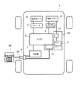
図1に示すように、電動車両の一例である電気自動車1には、高電圧の二次電池であるバッテリ2が搭載されている。バッテリ2はインバータ3を介して走行用モータ4に電気的に接続されている。走行用モータ4は、図示は省略するが駆動輪に連結されている。電気自動車1はこの走行用モータ4の駆動力によって走行する。バッテリ2には、DC/DCコンバータ5を介して補機バッテリ(12Vバッテリ)6が接続されている。DC/DCコンバータ5は、バッテリ2の出力電圧を所定値まで降圧させて補機バッテリ6に供給する。補機バッテリ6は、例えば、空調機器、オーディオ機器等の各種補機(図示なし)が接続されており、この補機バッテリ6から供給される電力によって各種補機が駆動されるようになっている。
As shown in FIG. 1, an electric vehicle 1 that is an example of an electric vehicle includes a
また電気自動車1は、バッテリ2を充電するための充電器7を備えている。充電器7は、給電コネクタ30が接続される電気自動車1の充電口(インレット)8とバッテリ2との間に設けられている。バッテリ2を充電する際には、給電コネクタ30を介して家庭用電源(外部電源)40と充電器7とが接続され、充電器7には家庭用電源40から100V程度の交流電力が入力される。充電器7では、家庭用電源40から入力された入力電力を350V程度の直流電力に変換・昇圧してバッテリ2の充電に適した充電用電力とする。この充電用電力がバッテリ2に入力されることで、バッテリ2が充電される。
In addition, the electric vehicle 1 includes a
また電気自動車1は、制御装置としてのECU(電子コントロールユニット)9を備え、電気自動車1は、ECU9によって総合的に制御される。ECU9は、入出力装置、記憶装置(ROM、RAM等)、中央処理装置(CPU)、タイマカウンタ等で構成されている。
The electric vehicle 1 includes an ECU (electronic control unit) 9 as a control device, and the electric vehicle 1 is comprehensively controlled by the
さらに電気自動車1には、バッテリ2の温度調整を行う温度調整装置10が搭載されている。温度調整装置10は、図2に示すように、バッテリ2を加熱する温調部11と、ECU9の一部として構成され温調部11の動作を制御する温調制御部12と、電動車両1の駐車中に所定のタイミングで温調制御部12を起動させる起動部13と、を備えている。
Furthermore, the electric vehicle 1 is equipped with a
温調部11は、バッテリ2を加熱するためのヒータ14と、バッテリ2の温度を検出する温度センサ15とを備え、ヒータ14によりバッテリ2を加熱してバッテリ2が所定温度となるように調整する。この温調部11は、給電コネクタ30を介して電気自動車1に接続された外部電源である家庭用電源40から供給される電力によって作動する。したがって温調部11は、給電コネクタ30がインレット8に接続されている場合にのみ作動することになる。
The
温調制御部12は、電源としての補機バッテリ6から供給される電力によって起動し、温調部11を構成するヒータ14等の動作を適宜制御する。本実施形態では、温調制御部12は、温度センサ15の検出結果に基づいてヒータ14の作動状態を適宜制御し、バッテリ2が所定の温度範囲となるように調整する。
The
起動部13は、電気自動車1の駐車中に、所定のタイミングで温調制御部12を起動させる。詳しくは、起動部13は、電源としての補機バッテリ6と温調制御部12との間に配置されるリレー部16を備える。このリレー部16は、コイル16aに電流が流れることで、リレー部16の端子間が接続されるように構成されている。リレー部16の端子間が接続されると、すなわち温調制御部12と補機バッテリ6との接続状態がオフ状態からオン状態に切り換わると、補機バッテリ6から温調制御部12に電力が供給されて温調制御部12が起動する。
The
また起動部13は、補機バッテリ6とリレー部16とを含む起動回路内に設けられるトランジスタ17と、電源である補機バッテリ6からトランジスタ18へ流れる電流を可変させるよう起動回路内に設けられるサーミスタ18と、を備えている。サーミスタ18は、ランジスタ17のベース端子17Bへ流れる電流を可変させるように、起動回路の補機バッテリ6からリレー部16に向かう経路とは分岐したトランジスタ17のベース端子17Bに向かう分岐経路に設けられている。本実施形態では、トランジスタ17のベース端子17Bと補機バッテリ6との間に、所定抵抗値の抵抗19が設けられており、サーミスタ18は、トランジスタ17及び抵抗19とは並列となるように配置されている。
The
また補機バッテリ6とサーミスタ18及び抵抗19との間の上記分岐経路には、スイッチ部20が設けられている。このスイッチ部20は、給電コネクタ30がインレット8に接続されると機械的にオンに切り換わるように構成されている。つまり起動部13は、給電コネクタ30がインレット8に接続されていることを条件に作動することになる。
A
そして起動部13は、サーミスタ18の温度が所定閾値を超えた際、本実施形態では、サーミスタ18の温度が所定閾値を超えて当該閾値よりも低くなった際、リレー部16がオフ状態からオン状態に切り換わるように構成されている。
In the present embodiment, when the temperature of the
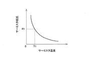
ここで、サーミスタ18は、いわゆるNTCサーミスタであり、図3に示すように、その温度が低いほど抵抗値が高くなる特性を有している。このサーミスタ18の温度が比較的高い状態、つまりバッテリ2の温度が比較的高い状態では、サーミスタ18は、抵抗19の抵抗値R1よりも低くなっている。この状態では、補機バッテリ6からの電力は上記分岐経路のサーミスタ18側に供給され、抵抗19側に供給されることはない。すなわちトランジスタ17のベース端子17Bとエミッタ端子17Eとの間に電流が流れることはない。このため、コレクタ端子17Cとエミッタ端子17E間にも電流は流れない。したがって、リレー部16のコイル16aに電力が供給されることはなく、リレー部16はオフ状態のまま維持されることになる。
Here, the
サーミスタ18の温度が所定温度T1よりも低い温度まで低下し、サーミスタ18の抵抗値が抵抗19の抵抗値R1よりも高くなると、すなわち抵抗19の抵抗値R1がサーミスタ18の抵抗値よりも低くなると、補機バッテリ6の電力は上記分岐経路のサーミスタ18側ではなく抵抗19側に供給される。そしてトランジスタ17のベース端子17Bとエミッタ端子17Eとの間に電流が流れ、コレクタ端子17Cとエミッタ端子17E間にも電流が流れるようになる。つまりリレー部16のコイル16aにも電力が供給されるようになる。これによりリレー部16がオフ状態からオン状態に切り換わり補機バッテリ6から温調制御部12を含むECU9に電力が供給される。
When the temperature of the
そして温調制御部12が起動し、必要に応じてバッテリ2の温調制御を実行する。すなわち、温調制御部12は、外部電源である家庭用電源40から給電コネクタ30を介して供給される電力によってヒータ14を作動させてバッテリ2を加熱する。また温調制御部12は、温度センサ15の検出結果に基づいてヒータ14の動作を適宜制御し、バッテリ2の温度が所定範囲となるように調整する。なおバッテリ2の温度調整の方法自体は、特に限定されるものではなく、公知の技術を採用すればよい。
And the
このような本発明に係る車載バッテリの温度調整装置10によれば、バッテリ2を適宜加熱することで、バッテリ2の温度を所望の温度範囲に維持することができる。また温度調整装置10は、電気自動車1の駐車中、バッテリ2の温度が予め設定された所定閾値よりも低くなった場合にのみ、起動部13によってECU9に電力を供給して温調制御部12を起動させる。したがって、温調制御部12を含むECU9の起動を最小限に抑制することができ、電気自動車1の停車中における電力消費を抑制することができる。またECU9の起動を抑制することで、ECU9の寿命を延ばすこともできる。なお電気自動車1の駐車中は、起動部13でも電力を消費しているが、抵抗値を調整する等によりその電力消費量は、ECU9の起動に必要な電力量より少なくすることもできる。
According to such a
また本実施形態では、起動部13がスイッチ部20を備え、給電コネクタ30がインレット8に接続されていることを条件に作動するため、ECU9の不要な起動を抑制され、電力消費量をより確実に減少させることができる。
Moreover, in this embodiment, since the starting
また本実施形態に係る温度調整装置10では、温調部11がバッテリ2の電力を使用することなく、外部電源である家庭用電源40から供給される電力によって作動するようにしている。これにより、例えば、極低温状態のように出力特性が著しく低下した状態でのバッテリ2の使用を防止することができる。勿論、温調部11は、バッテリ2や補機バッテリ6から供給される電力によって作動するようにしてもよい。
Moreover, in the
ところで、上述の本実施形態では、トランジスタ17とサーミスタ18とを並列に配置した構成を例示したが、図4に示すように、トランジスタ17とサーミスタ18とを直列に配置するようにしてもよい。この場合、サーミスタ18としては、図5に示すように温度が低くなるほど抵抗値が低くなる特性を有する、いわゆるPTCサーミスタを使用する。そして、サーミスタ18の温度が所定閾値T2よりも低くなると、サーミスタ18の抵抗値が所定の抵抗値R2よりも低くなりトランジスタ17のベース端子17Bとエミッタ端子17Eとの間に所定量の電流が流れるようにする。これにより、トランジスタ17とサーミスタ18とを並列に配置した場合と同様に、温調制御部12を含むECU9を適切なタイミングで起動させることができる。
By the way, in the above-described embodiment, the configuration in which the
以上、本発明の一実施形態について説明したが、本発明は上述の実施形態に限定されるものではない。 Although one embodiment of the present invention has been described above, the present invention is not limited to the above-described embodiment.
例えば、上述の実施形態では、温調部がヒータを備え、バッテリの温度が低下した際にバッテリを加熱して所定温度に調整する構成を例示したが、本発明に係る車載バッテリの温度調整装置の構成は、これに限定されるものではない。温調部は、バッテリの温度が所定閾値を超えて上昇した際にバッテリを冷却するように構成されていてもよい。これによりバッテリが極高温状態となるのを抑制でき、バッテリの劣化を抑えることができる。 For example, in the above-described embodiment, the temperature adjustment unit includes a heater, and when the temperature of the battery decreases, the battery is heated and adjusted to a predetermined temperature. However, the configuration is not limited to this. The temperature adjustment unit may be configured to cool the battery when the temperature of the battery rises above a predetermined threshold. Thereby, it can suppress that a battery becomes a very high temperature state, and can suppress deterioration of a battery.
また上述の実施形態では、補機バッテリから起動部及び温調制御部(ECU)に電力が供給されるようにしたが、起動部及び温調制御部に電力を供給する電源の構成は特に限定されない。例えば、外部電源である家庭用電源から起動部及び温調制御部に電力が供給されるようにしてもよい。また起動部と温調制御部には、それぞれ別の電源から電力が供給されるようにしてもよい。 In the above-described embodiment, power is supplied from the auxiliary battery to the starter and the temperature control unit (ECU). However, the configuration of the power source that supplies power to the starter and the temperature control unit is particularly limited. Not. For example, electric power may be supplied from the household power source, which is an external power source, to the activation unit and the temperature control unit. In addition, power may be supplied from separate power sources to the activation unit and the temperature control unit.
また上述の実施形態では、電動車両の一例として、電気自動車(EV)を例示して本発明を説明したが、勿論、本発明は、高電圧の車載バッテリを備える各種の電動車両に適用可能である。本発明は、例えば、走行用モータと共にエンジン(内燃機関)を駆動装置として備えるハイブリッド車両等にも適用することができる。 In the above-described embodiment, the present invention has been described by exemplifying an electric vehicle (EV) as an example of the electric vehicle. However, the present invention can be applied to various electric vehicles including a high-voltage on-vehicle battery. is there. The present invention can also be applied to, for example, a hybrid vehicle including an engine (internal combustion engine) as a drive device together with a traveling motor.
1 電気自動車(電動車両)
2 バッテリ
3 インバータ
4 走行用モータ
5 コンバータ
6 補機バッテリ
7 充電器
8 インレット
9 ECU
10 温度調整装置
11 温調部
12 温調制御部
13 起動部
14 ヒータ
15 温度センサ
16 リレー部
16a コイル
17 トランジスタ
18 サーミスタ
19 抵抗
20 スイッチ部
30 給電コネクタ
40 家庭用電源(外部電源)
1 Electric vehicle (electric vehicle)
2
DESCRIPTION OF
Claims (5)
前記車載バッテリを加熱又は冷却する温調部と、該温調部の動作を制御する温調制御部と、前記電動車両の駐車中に所定のタイミングで前記温調制御部を起動させる起動部と、を備え、
前記起動部は、
前記温調制御部と電源との間に配置されて前記温調制御部と前記電源との接続をオン又はオフに切り換えるリレー部と、
前記電源と前記リレー部とを含む起動回路内に設けられるトランジスタと、
前記電源から前記トランジスタへ流れる電流を可変させるよう前記起動回路内に設けられるサーミスタと、を備え、
前記サーミスタの温度が所定閾値を超えた際に前記リレー部がオンに切り換わるように構成されている
ことを特徴とする車載バッテリの温度調整装置。 A temperature adjustment device for an in-vehicle battery that adjusts the temperature of an in-vehicle battery that supplies electric power to a traveling motor of an electric vehicle,
A temperature control unit for heating or cooling the in-vehicle battery, a temperature control unit for controlling the operation of the temperature control unit, and an activation unit for starting the temperature control unit at a predetermined timing while the electric vehicle is parked. With
The activation unit is
A relay unit that is arranged between the temperature control unit and the power source and switches the connection between the temperature control unit and the power source on or off;
A transistor provided in an activation circuit including the power source and the relay unit;
A thermistor provided in the startup circuit to vary the current flowing from the power source to the transistor,
The vehicle-mounted battery temperature adjustment device, wherein the relay unit is turned on when the temperature of the thermistor exceeds a predetermined threshold.
前記起動部は、前記サーミスタの温度が所定閾値よりも低くなると、前記リレー部がオンに切り換わるように構成されている
ことを特徴とする車載バッテリの温度調整装置。 In the vehicle battery temperature adjustment device according to claim 1,
The in-vehicle battery temperature adjusting device, wherein the activation unit is configured to turn on the relay unit when the temperature of the thermistor becomes lower than a predetermined threshold.
前記サーミスタは、該サーミスタの温度が低いほど抵抗値が高くなる特性を有し、前記トランジスタと並列に配置されている
ことを特徴とする車載バッテリの温度調整装置。 In the vehicle battery temperature adjustment device according to claim 2,
The on-board battery temperature adjusting device, wherein the thermistor has a characteristic that a resistance value increases as the temperature of the thermistor decreases, and is disposed in parallel with the transistor.
前記サーミスタは、該サーミスタの温度が低いほど抵抗値が低くなる特性を有し、前記トランジスタと直列に配置されている
ことを特徴とする車載バッテリの温度調整装置。 In the vehicle battery temperature adjustment device according to claim 2,
The on-board battery temperature adjusting device, wherein the thermistor has a characteristic that a resistance value decreases as the temperature of the thermistor decreases, and is disposed in series with the transistor.
前記起動部は、外部電源が前記電動車両に接続されていることを条件に、前記トランジスタと前記電源との接続をオンとするスイッチ部を有する
ことを特徴とする車載バッテリの温度調整装置。 In the vehicle battery temperature regulating device according to any one of claims 1 to 4,
The in-vehicle battery temperature adjustment device, wherein the starting unit includes a switch unit that turns on the connection between the transistor and the power source on condition that an external power source is connected to the electric vehicle.
Priority Applications (1)
| Application Number | Priority Date | Filing Date | Title |
|---|---|---|---|
| JP2015226042A JP6579320B2 (en) | 2015-11-18 | 2015-11-18 | In-vehicle battery temperature control device |
Applications Claiming Priority (1)
| Application Number | Priority Date | Filing Date | Title |
|---|---|---|---|
| JP2015226042A JP6579320B2 (en) | 2015-11-18 | 2015-11-18 | In-vehicle battery temperature control device |
Publications (2)
| Publication Number | Publication Date |
|---|---|
| JP2017097971A JP2017097971A (en) | 2017-06-01 |
| JP6579320B2 true JP6579320B2 (en) | 2019-09-25 |
Family
ID=58817961
Family Applications (1)
| Application Number | Title | Priority Date | Filing Date |
|---|---|---|---|
| JP2015226042A Active JP6579320B2 (en) | 2015-11-18 | 2015-11-18 | In-vehicle battery temperature control device |
Country Status (1)
| Country | Link |
|---|---|
| JP (1) | JP6579320B2 (en) |
Families Citing this family (4)
| Publication number | Priority date | Publication date | Assignee | Title |
|---|---|---|---|---|
| CN111361457B (en) * | 2018-12-26 | 2021-12-21 | 郑州宇通客车股份有限公司 | Vehicle and heating control method of power battery of vehicle |
| WO2021044479A1 (en) * | 2019-09-02 | 2021-03-11 | 日産自動車株式会社 | Installation arrangement for drive motor and battery in vehicle |
| JP2022011148A (en) | 2020-06-29 | 2022-01-17 | 本田技研工業株式会社 | Battery management support device and battery management support method |
| JP7399992B2 (en) | 2022-01-21 | 2023-12-18 | 本田技研工業株式会社 | Battery temperature control system |
Family Cites Families (3)
| Publication number | Priority date | Publication date | Assignee | Title |
|---|---|---|---|---|
| JP2006262647A (en) * | 2005-03-17 | 2006-09-28 | Hitachi Ltd | Apparatus controller |
| JP2008295291A (en) * | 2007-04-27 | 2008-12-04 | Sanyo Electric Co Ltd | Power supply apparatus and electric vehicle |
| JP6232878B2 (en) * | 2013-09-24 | 2017-11-22 | トヨタ自動車株式会社 | Power storage system |
-
2015
- 2015-11-18 JP JP2015226042A patent/JP6579320B2/en active Active
Also Published As
| Publication number | Publication date |
|---|---|
| JP2017097971A (en) | 2017-06-01 |
Similar Documents
| Publication | Publication Date | Title |
|---|---|---|
| US9919710B2 (en) | Power storage system | |
| JP6229539B2 (en) | Vehicle battery control device | |
| JP6579320B2 (en) | In-vehicle battery temperature control device | |
| CN109263436B (en) | Parking heating system | |
| JP5736860B2 (en) | Battery charge control device | |
| WO2012124487A1 (en) | Battery charging control device | |
| US20130033232A1 (en) | Storage battery device | |
| JP2016152067A (en) | Power storage system | |
| JP2014075297A (en) | Power storage system | |
| US11155221B2 (en) | Power supply device for vehicle | |
| JP2009213223A (en) | Voltage converter | |
| JP5929678B2 (en) | Control device for hybrid vehicle | |
| JP2012188062A (en) | Air conditioning control device of hybrid vehicle | |
| JP2016111721A (en) | Charge control device of vehicle | |
| JP6402687B2 (en) | Vehicle battery system | |
| JP6079725B2 (en) | Vehicle power supply control device | |
| JP6348293B2 (en) | Air conditioner for vehicles | |
| JP6156004B2 (en) | Air conditioning control device for vehicles | |
| JP6358025B2 (en) | Electric water pump device | |
| JP4696933B2 (en) | Defrosting device for vehicles | |
| JP6094753B2 (en) | Charge control device | |
| JP2019088110A (en) | Power supply controller and power supply system | |
| JP6238034B2 (en) | Charge control device | |
| JP2010215177A (en) | Vehicle | |
| JP2018153000A (en) | Battery temperature adjustment device |
Legal Events
| Date | Code | Title | Description |
|---|---|---|---|
| A621 | Written request for application examination |
Free format text: JAPANESE INTERMEDIATE CODE: A621 Effective date: 20181026 |
|
| A977 | Report on retrieval |
Free format text: JAPANESE INTERMEDIATE CODE: A971007 Effective date: 20190708 |
|
| TRDD | Decision of grant or rejection written | ||
| A01 | Written decision to grant a patent or to grant a registration (utility model) |
Free format text: JAPANESE INTERMEDIATE CODE: A01 Effective date: 20190731 |
|
| A61 | First payment of annual fees (during grant procedure) |
Free format text: JAPANESE INTERMEDIATE CODE: A61 Effective date: 20190813 |
|
| R151 | Written notification of patent or utility model registration |
Ref document number: 6579320 Country of ref document: JP Free format text: JAPANESE INTERMEDIATE CODE: R151 |