JP6228552B2 - Battery pack system and storage battery system - Google Patents
Battery pack system and storage battery system Download PDFInfo
- Publication number
- JP6228552B2 JP6228552B2 JP2014553999A JP2014553999A JP6228552B2 JP 6228552 B2 JP6228552 B2 JP 6228552B2 JP 2014553999 A JP2014553999 A JP 2014553999A JP 2014553999 A JP2014553999 A JP 2014553999A JP 6228552 B2 JP6228552 B2 JP 6228552B2
- Authority
- JP
- Japan
- Prior art keywords
- storage battery
- management device
- battery module
- communication
- storage
- Prior art date
- Legal status (The legal status is an assumption and is not a legal conclusion. Google has not performed a legal analysis and makes no representation as to the accuracy of the status listed.)
- Active
Links
Images


Classifications
-
- H—ELECTRICITY
- H01—ELECTRIC ELEMENTS
- H01M—PROCESSES OR MEANS, e.g. BATTERIES, FOR THE DIRECT CONVERSION OF CHEMICAL ENERGY INTO ELECTRICAL ENERGY
- H01M10/00—Secondary cells; Manufacture thereof
- H01M10/42—Methods or arrangements for servicing or maintenance of secondary cells or secondary half-cells
- H01M10/48—Accumulators combined with arrangements for measuring, testing or indicating the condition of cells, e.g. the level or density of the electrolyte
- H01M10/482—Accumulators combined with arrangements for measuring, testing or indicating the condition of cells, e.g. the level or density of the electrolyte for several batteries or cells simultaneously or sequentially
-
- G—PHYSICS
- G01—MEASURING; TESTING
- G01R—MEASURING ELECTRIC VARIABLES; MEASURING MAGNETIC VARIABLES
- G01R31/00—Arrangements for testing electric properties; Arrangements for locating electric faults; Arrangements for electrical testing characterised by what is being tested not provided for elsewhere
- G01R31/36—Arrangements for testing, measuring or monitoring the electrical condition of accumulators or electric batteries, e.g. capacity or state of charge [SoC]
- G01R31/371—Arrangements for testing, measuring or monitoring the electrical condition of accumulators or electric batteries, e.g. capacity or state of charge [SoC] with remote indication, e.g. on external chargers
-
- H—ELECTRICITY
- H01—ELECTRIC ELEMENTS
- H01M—PROCESSES OR MEANS, e.g. BATTERIES, FOR THE DIRECT CONVERSION OF CHEMICAL ENERGY INTO ELECTRICAL ENERGY
- H01M10/00—Secondary cells; Manufacture thereof
- H01M10/42—Methods or arrangements for servicing or maintenance of secondary cells or secondary half-cells
- H01M10/425—Structural combination with electronic components, e.g. electronic circuits integrated to the outside of the casing
-
- H—ELECTRICITY
- H02—GENERATION; CONVERSION OR DISTRIBUTION OF ELECTRIC POWER
- H02J—ELECTRIC POWER NETWORKS; CIRCUIT ARRANGEMENTS OR SYSTEMS FOR SUPPLYING OR DISTRIBUTING ELECTRIC POWER; SYSTEMS FOR STORING ELECTRIC ENERGY
- H02J7/00—Circuit arrangements for charging or discharging batteries or for supplying loads from batteries
- H02J7/50—Circuit arrangements for charging or discharging batteries or for supplying loads from batteries acting upon multiple batteries simultaneously or sequentially
-
- H—ELECTRICITY
- H02—GENERATION; CONVERSION OR DISTRIBUTION OF ELECTRIC POWER
- H02J—ELECTRIC POWER NETWORKS; CIRCUIT ARRANGEMENTS OR SYSTEMS FOR SUPPLYING OR DISTRIBUTING ELECTRIC POWER; SYSTEMS FOR STORING ELECTRIC ENERGY
- H02J7/00—Circuit arrangements for charging or discharging batteries or for supplying loads from batteries
- H02J7/80—Circuit arrangements for charging or discharging batteries or for supplying loads from batteries including monitoring or indicating arrangements
- H02J7/82—Control of state of charge [SOC]
-
- G—PHYSICS
- G01—MEASURING; TESTING
- G01R—MEASURING ELECTRIC VARIABLES; MEASURING MAGNETIC VARIABLES
- G01R31/00—Arrangements for testing electric properties; Arrangements for locating electric faults; Arrangements for electrical testing characterised by what is being tested not provided for elsewhere
- G01R31/36—Arrangements for testing, measuring or monitoring the electrical condition of accumulators or electric batteries, e.g. capacity or state of charge [SoC]
- G01R31/396—Acquisition or processing of data for testing or for monitoring individual cells or groups of cells within a battery
-
- H—ELECTRICITY
- H01—ELECTRIC ELEMENTS
- H01M—PROCESSES OR MEANS, e.g. BATTERIES, FOR THE DIRECT CONVERSION OF CHEMICAL ENERGY INTO ELECTRICAL ENERGY
- H01M10/00—Secondary cells; Manufacture thereof
- H01M10/42—Methods or arrangements for servicing or maintenance of secondary cells or secondary half-cells
- H01M10/425—Structural combination with electronic components, e.g. electronic circuits integrated to the outside of the casing
- H01M2010/4271—Battery management systems including electronic circuits, e.g. control of current or voltage to keep battery in healthy state, cell balancing
-
- H—ELECTRICITY
- H01—ELECTRIC ELEMENTS
- H01M—PROCESSES OR MEANS, e.g. BATTERIES, FOR THE DIRECT CONVERSION OF CHEMICAL ENERGY INTO ELECTRICAL ENERGY
- H01M10/00—Secondary cells; Manufacture thereof
- H01M10/42—Methods or arrangements for servicing or maintenance of secondary cells or secondary half-cells
- H01M10/425—Structural combination with electronic components, e.g. electronic circuits integrated to the outside of the casing
- H01M2010/4278—Systems for data transfer from batteries, e.g. transfer of battery parameters to a controller, data transferred between battery controller and main controller
-
- Y—GENERAL TAGGING OF NEW TECHNOLOGICAL DEVELOPMENTS; GENERAL TAGGING OF CROSS-SECTIONAL TECHNOLOGIES SPANNING OVER SEVERAL SECTIONS OF THE IPC; TECHNICAL SUBJECTS COVERED BY FORMER USPC CROSS-REFERENCE ART COLLECTIONS [XRACs] AND DIGESTS
- Y02—TECHNOLOGIES OR APPLICATIONS FOR MITIGATION OR ADAPTATION AGAINST CLIMATE CHANGE
- Y02E—REDUCTION OF GREENHOUSE GAS [GHG] EMISSIONS, RELATED TO ENERGY GENERATION, TRANSMISSION OR DISTRIBUTION
- Y02E60/00—Enabling technologies; Technologies with a potential or indirect contribution to GHG emissions mitigation
- Y02E60/10—Energy storage using batteries
Landscapes
- Engineering & Computer Science (AREA)
- Power Engineering (AREA)
- Chemical Kinetics & Catalysis (AREA)
- Chemical & Material Sciences (AREA)
- Electrochemistry (AREA)
- General Chemical & Material Sciences (AREA)
- Manufacturing & Machinery (AREA)
- Physics & Mathematics (AREA)
- General Physics & Mathematics (AREA)
- Microelectronics & Electronic Packaging (AREA)
- Charge And Discharge Circuits For Batteries Or The Like (AREA)
- Battery Mounting, Suspending (AREA)
- Secondary Cells (AREA)
Description
本発明は、組電池システム及び蓄電池システムに関する。 The present invention also relates to a battery pack system and the battery system.
陸海空の乗り物(船舶、鉄道、自動車等)における駆動システム、バックアップ用のUPS(Uninterruptible Power Supply:無停電電源装置)、電力系統安定化のための大規模蓄電設備など、様々な分野において鉛電池やリチウムイオン電池などの二次電池が用いられている。これらの蓄電池設備では、システムに要求される出力、容量を得るため、多数の二次電池セル、及び/又は二次電池モジュールを直列、及び並列に接続して蓄電池システムを構成する。二次電池は、その化学的な性質から充放電可能な電流や電力量が決まっており、これを超えて充放電を行うと性能の急激な劣化や故障を引き起こすおそれがある。これらを防ぐために二次電池の状態を監視しながら充放電を行う必要がある。また、蓄電池システムに流れ込む電流は、時々刻々と変化することから、特に短い時間で大きな電流変化が生じると想定される蓄電池システムにおいては、その安全性を確保するため、早い周期で電池情報を収集することが求められる。また、蓄電池システムを構成する各蓄電池モジュールの電圧、電流、温度、電池容量等の状態情報の計測誤差を最小にするため、高い時刻精度で同時に蓄電池モジュールの状態を計測する必要がある。 Lead batteries in various fields such as drive systems for land, sea and air vehicles (ships, railways, automobiles, etc.), backup UPS (Uninterruptible Power Supply), large-scale power storage facilities for power system stabilization, etc. Secondary batteries such as lithium ion batteries are used. In these storage battery facilities, in order to obtain the output and capacity required for the system, a large number of secondary battery cells and / or secondary battery modules are connected in series and in parallel to constitute a storage battery system. The secondary battery has a current and amount of electric power that can be charged / discharged due to its chemical properties, and charging / discharging beyond this level may cause rapid deterioration or failure of performance. In order to prevent these, it is necessary to charge and discharge while monitoring the state of the secondary battery. In addition, since the current flowing into the storage battery system changes from moment to moment, battery information is collected at an early cycle in order to ensure its safety, especially in storage battery systems that are expected to undergo large current changes in a short time. It is required to do. In addition, in order to minimize measurement errors in state information such as voltage, current, temperature, and battery capacity of each storage battery module constituting the storage battery system, it is necessary to simultaneously measure the state of the storage battery module with high time accuracy.
従来の組電池システムは、蓄電池モジュールを不燃性である金属筐体内に設置し、電池コントローラが各蓄電池モジュールの状態を監視する。電池コントローラは、各蓄電池モジュールと有線で接続され、定期的に電圧等の情報を収集する。しかし、配線多数で絶縁やメンテナンス(定期検査)にコストがかかることから通信を無線化することが提案されている。 In a conventional assembled battery system, a storage battery module is installed in a metal casing that is incombustible, and a battery controller monitors the state of each storage battery module. The battery controller is connected to each storage battery module by wire and periodically collects information such as voltage. However, it has been proposed to wirelessly communicate because many wires are expensive to insulate and maintain (periodic inspection).
特許文献1には、複数の電池セルを直列接続して構成した組電池システムにおいて、電池セルの電池情報を無線信号により管理装置に送信する組電池システムが記載されている。
しかしながら、特許文献1のように、金属筐体の内部に無線通信用のアンテナが設置される組電池システムでは、金属製の筐体内部で電波が反射することで多数の反射波が生成され、アンテナ間の伝搬路は複数のパスを持つマルチパス環境となる。このため、アンテナの受信点では、複数の電波が合成され、アンテナの位置や通信周波数に依存して伝搬特性が大きく変化する。例えば、ある通信チャネルでは電波伝搬特性が良好であるのに対し、他の通信チャネルでは電波伝搬特性が大きく落ち込む場合がある。電波伝搬特性は、周波数に依存して大きく変化することから、ある周波数での通信において、管理装置側と蓄電池モジュールとの間で通信ができない可能性がある。この場合、当該周波数において電波伝搬特性が劣化している蓄電池モジュールに計測指示が伝達されないという課題がある。
However, as in
一方、組電池システムの放熱等のために金属筐体による電波の封止が完全でない場合、組電池システムを複数直列、及び/又は並列に接続して用いるような蓄電池システムでは隣接する組電池システム同士の通信が干渉するという課題がある。また、組電池システムから電波の漏洩がある場合、事前に金属筐体内部の伝搬特性の調整を行ったとしても周辺の環境によって筐体内部の伝搬特性が変化することから、金属筐体内の電波伝搬の落込みを回避しつつ隣接システムとの干渉を避けるための方法が求められる。 On the other hand, in the case of a storage battery system in which a plurality of battery pack systems are connected in series and / or in parallel when radio wave sealing by a metal casing is not complete due to heat dissipation of the battery pack system, adjacent battery pack systems are used. There is a problem that communication between each other interferes. Also, if there is radio wave leakage from the battery pack system, the propagation characteristics inside the housing will change depending on the surrounding environment even if the propagation characteristics inside the metal housing are adjusted in advance. There is a need for a method for avoiding interference with adjacent systems while avoiding a drop in propagation.
本発明の目的は、適切に通信することのできる組電池システム及び蓄電池システムを提供することである。
An object of the present invention is to provide an assembled battery system and battery system capable of communicating properly.
前記課題を解決するため、本発明による電池システムは、直列、並列、又は直並列に接続された複数の蓄電池を含んでなる蓄電池モジュールに属する各蓄電池の電池状態を監視して電池情報を取得する電池監視部を有するとともに、前記電池情報を、当該蓄電池モジュールが収容される金属筐体内において無線により伝送する通信部を有する蓄電池モジュール側管理装置と、前記金属筐体内に複数収容される各蓄電池モジュールにそれぞれ備わる前記蓄電池モジュール側管理装置と前記金属筐体内において相互に無線通信して、それぞれの前記蓄電池モジュールを管理する管理装置とを具備し、前記管理装置は、前記各蓄電池モジュール側管理装置に対し、次の計測タイミングを指定する情報を含む計測指示を所定の間隔で送信し、前記電池監視部に対して、前記計測指示に従って、それぞれの前記蓄電池モジュール間において一斉に蓄電池の電池状態を計測させるように制御し、前記管理装置は、前記蓄電池モジュール側管理装置からの応答を受信できなかった場合、当該蓄電池モジュール側管理装置に対し、通信周波数を変えて前記計測指示を再送することを特徴とする。 In order to solve the above problems, a battery system according to the present invention acquires battery information by monitoring a battery state of each storage battery belonging to a storage battery module including a plurality of storage batteries connected in series, parallel, or series-parallel. A storage battery module-side management device having a battery monitoring unit and having a communication unit that wirelessly transmits the battery information in a metal casing in which the storage battery module is stored, and a plurality of storage battery modules stored in the metal casing Each of the storage battery module side management device and a management device that manages each of the storage battery modules by wirelessly communicating with each other in the metal casing, and the management device is connected to each storage battery module side management device. On the other hand, a measurement instruction including information specifying the next measurement timing is transmitted at a predetermined interval, and the battery With respect to the visual portion, according to the measurement instruction, simultaneously controlled so as to measure a battery status of the battery between each of the battery modules, the management device may not receive a response from the storage battery module side management apparatus In this case, the measurement instruction is retransmitted by changing the communication frequency to the storage battery module side management device .
本発明による蓄電池電池システムは、前記組電池システムを複数並べて構成した蓄電池システムにおいて、前記各組電池システムの通信時間、通信周波数、通信空間、又は拡散符号のうちいずれかを前記組電池システムごとに変えることを特徴とする。 The storage battery system according to the present invention is a storage battery system configured by arranging a plurality of the assembled battery systems, wherein any one of the communication time, the communication frequency, the communication space, and the spread code of each of the assembled battery systems is set for each of the assembled battery systems. It is characterized by changing.
本発明によれば、適切に通信することのできる組電池システム及び蓄電池システムを提供することができる。 According to the present invention, it is possible to provide a battery pack system and accumulators systems capable of communicating properly.
以下、本発明の実施形態について図面を参照して詳細に説明する。
(第1の実施形態)
図1は、本発明の第1の実施形態に係る組電池システムを複数並べた蓄電池システムの構成を示す図である。本実施形態の蓄電池システムは、複数の電池セルの監視制御と管理を無線信号により行う組電池システムに適用した例である。Hereinafter, embodiments of the present invention will be described in detail with reference to the drawings.
(First embodiment)
FIG. 1 is a diagram showing a configuration of a storage battery system in which a plurality of assembled battery systems according to the first embodiment of the present invention are arranged. The storage battery system of this embodiment is an example applied to an assembled battery system that performs monitoring control and management of a plurality of battery cells by radio signals.
〔全体構成〕
図1に示すように、蓄電池システム10は、複数配置した組電池システム100−1〜100−nと、組電池システム100−1〜100−n全体を管理する蓄電池システムコントローラ20と、を備えて構成される。組電池システム100−1〜100−nは、同一構成であるため、組電池システム100−3を代表して示す。なお、以下の説明において、組電池システム100−1〜100−nを特に区別しない場合には、組電池システム100と記す。〔overall structure〕
As shown in FIG. 1, the
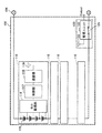
組電池システム100は、複数(ここでは一列4個ずつ4段)整列配置された蓄電池モジュール110と、管理装置120と、を備える。
組電池システム100は、金属筐体101からなる電池ラックに収容される。金属筐体101の前面には、金属製の扉102と、扉102を開閉するための取手103が設けられ、必要に応じて内部の蓄電池モジュール110を点検、交換可能な構造となっている。扉102には、メッシュ状の穴102aが設けられ金属筐体内を冷却するための空気を取り込むことができる。メッシュ状の穴102aの長辺は、金属筐体101内部の無線通信の電波の波長の半分よりも短いものとする。金属筐体101が一つの組電池システム100の筺体を構成する。管理装置120も同様に、金属筐体21に収容され、金属筐体21の前面に金属製の扉22と、扉22を開閉するための取手33が設けられる。扉22には、メッシュ状の穴22aが設けられる。
組電池システム100は、金属筐体101で覆われており、外部に無線通信信号が漏れず、外部の他システムの無線通信信号の干渉を受けないため、良好な通信品質が得られる。なお、金属筐体101を構成する導体は波長よりも十分小さい格子を持つメッシュ状でもよい。The assembled
The assembled
The assembled
図1に示すように、各蓄電池モジュール110を収容した複数の小ケース111と、管理装置120を収容した小ケース121と、を複数段重ねて金属筐体101に固定する。金属筐体101は、電池ラックを構成し、この電池ラック一つが組電池システム100一つに対応する。図1では、組電池システム100−1〜100−nと、蓄電池システムコントローラ20と、が蓄電池システム10を構成している。また、金属筐体101の内部に4個の蓄電池モジュール110を格納し、金属筐体101の内側下部に管理装置120を設置した例である。金属筐体101の下部から外部電極インタフェース104が出力されている。
As shown in FIG. 1, a plurality of
組電池システム100内の管理装置120によって収集された各蓄電池モジュールの情報は、外部電極インタフェース104を介して組電池システム100−1〜100−nごとに管理装置120から上位コントローラである蓄電池システムコントローラ20に伝達され、蓄電池システムコントローラ20が蓄電池システム100全体を管理する。
金属筐体101内部で無線通信を行う組電池システム100を複数並べて蓄電池システム10を構成する場合、組電池システム100同士の無線電波が干渉しないようにする必要がある。The information of each storage battery module collected by the
When the
図2は、上記組電池システム100の構成を示す図であり、(a)は内部を透過して示す斜視図、(b)はその側面図である。
図2に示すように、各蓄電池モジュール110は、ガイド112によって空冷及び絶縁のための間隔を設けた状態で金属製の小ケース111に固定される。小ケース111は、各蓄電池モジュール110を整列配置し、背面に電極端子113と、空冷用のファン114とを備える。蓄電池モジュール110の電極端子110aと小ケース111背面の電極端子113とは、1:1で対応し、電極端子113の接続方法を変えることで各蓄電池モジュール110の直列/並列の構成を変更することができる。なお、放熱のために空冷用のファン114を設けている。因みに、金属ケースは、熱伝導が良く、電池の温度コントロールをし易い一方、電波を反射や遮蔽する特徴を有する。
なお、各蓄電池モジュール110、小ケース111、及び組電池システム100−1〜100−n等の配置・設置数・形状は一例であり、どのような構成でもよい。2A and 2B are diagrams showing the configuration of the assembled
As shown in FIG. 2, each
In addition, arrangement | positioning / installation number / shape of each
〔組電池システムの内部構成〕
図3は、上記蓄電池モジュール110の構成を示す図である。図4は、上記各蓄電池モジュール110を備える組電池システム100の構成を示す図である。[Internal configuration of battery pack system]
FIG. 3 is a diagram showing the configuration of the
[蓄電池モジュール110]
図3及び図4に示すように、蓄電池モジュール110は、直列に接続された二次電池115、セル監視部116、制御部117、通信部118、及びアンテナ119を備える。図3及び図4では、二次電池115にセル監視部116(電池監視部)、制御部117、通信部118及びアンテナ119を接続し、これらを一つの蓄電池モジュール110としている。[Storage battery module 110]
As shown in FIGS. 3 and 4, the
二次電池115は、複数の電池セルを直列、並列、又は直並列に接続したものである。また、最上位電位の電極と最下位電位の電極が外部電極インタフェース104(図4参照)として出力される。このとき、外部電極インタフェース104は高電圧を印加したり大電流を流したりすることができるため、誤って高電圧や大電流を出力しないように、所定の条件においてのみオンとなるスイッチ124(図4参照)を備える。なお、金属筐体101の外部に出力する場合は、金属筐体101と外部電極インタフェース104の間の隙間を無線通信で用いる波長よりも十分に小さくしておくと、外部に無線通信信号が漏れたり、外部の他システムの無線通信信号の干渉を受けたりしない。
The
セル監視部116は、直列、並列、又は直並列に接続された複数の蓄電池を含んでなる蓄電池モジュールに属する各蓄電池の電池状態を監視して電池情報を取得する。セル監視部116は、制御部117からの要求に応じてセル情報の計測値を渡す。セル監視部116は、常時計測するものと、制御部116からの要求があって始めて計測をスタートするものとがある。
The
制御部117は、マイクロコントローラから構成され、電池情報、計測指示(監視制御指示)及び無線通信モードなどを記憶しておく記憶部(図示略)を備える。制御部117は、管理装置120からの計測指示に従って、各蓄電池モジュール110間において一斉に二次電池115の電池状態を計測する蓄電池モジュール側管理装置としての機能を有する。制御部117は、管理装置120から受信した計測指示(監視制御指示)を基にセル監視部116に計測を指示し、セル監視部116から電池情報(電池情報)を取得する。また、制御部117は、通信部118により管理装置120との間で計測指示に関する通信制御を行う。ここで、電池情報の収集周期には、時間的な制約がある。すなわち、組電池システムに流れ込む電流は、時々刻々と変化することから、早い周期で、かつ蓄電池モジュール110間で電池情報取得タイミングを揃えて一斉に電池情報を収集することが求められる。電池情報収集周期については、図5により後記する。
The
無線通信部118は、電池情報を、当該蓄電池モジュールが収容される金属筐体101内において無線により伝送する無線回路等からなる。例えば、無線通信部118は、ZigBee(登録商標)、Bluetooth(登録商標)、UWB(Ultra Wideband)などの小電力近距離双方向無線通信方式を用いる。また、IEEE802.11x規格に基づく無線LAN(WLAN:Wireless Local Area Network)でもよい。また、無線通信の無線多重アクセス方式としてTDMA(Time Division Multiple Access)/FDMA(Frequency Division Multiple Access)/CDMA(Code Division Multiple Access)のうち、のいずれかを用いることができる。本実施形態では、蓄電池モジュール110間が時分割、組電池システム100間が周波数分割、蓄電池システム10と他の蓄電池システム10間が符号分割により無線通信を行う。通信部118は、無線によって電池情報を管理装置120に送信するとともに、管理装置120から計測指示(監視制御指示)を受信する。無線によるデータの送信方法としては、各蓄電池モジュール110が管理装置120からの同期信号を基準として予め決められたタイミングでデータ送信を行う方法と、管理装置120からの指示に対して逐次応答を返す方法がある。
アンテナ119は、棒状、コイル状、板状、又はプリント回路基板の導線パターンで形成したものでもよい。The
The
[管理装置120]
管理装置120(図4参照)は、蓄電池モジュール110側管理装置である制御部117と、金属筐体101内において相互に無線通信して、それぞれの蓄電池モジュールを管理する。管理装置120は、それぞれの制御部117(蓄電池モジュール側管理装置)に対し、次の計測タイミングを指定する情報を含む計測指示を所定の間隔で送信し、セル監視部116に対して、前記計測指示に従って、それぞれの前記蓄電池モジュール110間において一斉に蓄電池の電池状態を計測させるように制御する。
管理装置120は、管理ユニット122、及びアンテナ123を備える。管理ユニット122は、蓄電池モジュール110の制御部117及び通信部118と同様の制御部及び通信部(図示略)を備える。但し、管理ユニット122の制御部の制御プログラムは異なる。各蓄電池モジュール110及び管理装置120は、金属筐体101(図1参照)の内部に納められ、一つの組電池システム100を構成する。
蓄電池モジュール110は、アンテナ119,123を介して管理装置120と通信を行い、電池情報の伝達を行う。管理ユニット122は、異常を検出した場合、スイッチ124により電源線を遮断可能である。[Management device 120]
The management device 120 (see FIG. 4) manages each storage battery module by wirelessly communicating with the
The
The
管理装置120は、各蓄電池モジュール110に対し、次の計測時刻を指定する情報を含む計測指示を定期的に送信する。管理装置120は、二次電池115の電池情報を無線で取得することにより絶縁耐圧を確保し、電池情報を容易に収集することができる。
管理装置120は、各蓄電池モジュール110の電池情報を収集し、組電池システム100として所望の機能を果たすように各蓄電池モジュール110を監視制御する。具体的には、管理装置120は、二次電池115のセル電圧や温度などの情報を収集し、適切な電圧や温度で二次電池115が使用されているかを監視するとともに、二次電池115の残存電荷量(セル電圧)のばらつき小さくなるように制御する。これらの監視制御は周期的に行ったり、特定の条件に合致した場合に、外部システムからの要求や外部システムから提供される情報に基づいて行う。電池情報は、例えば、二次電池115のセル電圧や温度、内部抵抗値、残存電荷量、充放電状況、ID、不具合の有無、劣化度合いなどに関する情報である。
The
[電池情報の収集周期]
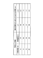
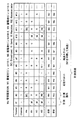
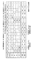
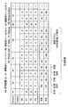
図5は、電池性能と電池情報収集周期の関係を説明する図である。
電池情報の収集周期は、電池セルの定格電流と容量、システムで必要なSOC(State Of Charge:電池充電率)の検出精度によって変わる。
図5に示すように、例えば容量10Ah,出力20Aの二次電池115でSOCを0.1%精度で検出しようとすると、全ての蓄電池モジュール110から1.8秒以内に電池情報を収集する必要がある。
このように、組電池システムは、電池情報収集周期に時間的な制約があることが、一般的な無線通信システムと異なる。[Battery information collection cycle]
FIG. 5 is a diagram for explaining the relationship between the battery performance and the battery information collection period.
The collection period of the battery information varies depending on the rated current and capacity of the battery cell and the detection accuracy of the SOC (State Of Charge) required for the system.
As shown in FIG. 5, for example, if the
As described above, the assembled battery system is different from a general wireless communication system in that the battery information collection cycle has a time restriction.
以下、上述のように構成された電池システム100の動作について説明する。
まず、本発明の基本的な考え方について説明する。
[組電池システム内の電波伝搬特性]
図6は、図2(a)の蓄電池モジュール110が収容された小ケース111内において、無線通信周波数を2.4GHzから2.5GHzまで変化させたときの場所ごとの電波伝搬特性を示す図である。図6は、小ケース111内の各蓄電池モジュール110の間の奥行きx=24cmの位置での電波伝搬特性を抽出したもの示す。なお、2.4GHz帯は、ZigBee(登録商標)、Bluetooth(登録商標)で利用可能な周波数帯である。Hereinafter, the operation of the
First, the basic concept of the present invention will be described.
[Radio wave propagation characteristics in battery pack system]
FIG. 6 is a diagram showing radio wave propagation characteristics for each place when the radio communication frequency is changed from 2.4 GHz to 2.5 GHz in the
図6(a)に示す測定経路1では、電波伝搬特性は良好である。しかし、図6(b)に示すように、金属製の小ケース111又は電池ラック(金属筐体101:組電池システム100)内では、電波が反射してマルチパス受信になることから、位置や周波数によって電波伝搬特性の落込みが生じる。この例では、2.468GHzで−74.2dBと電波伝搬特性が大きく落ち込んでいる。仮にこの周波数帯に割り当てられた通信チャネルがあると、当該通信チャネルを使用する蓄電池モジュールに計測指示が伝達されないという問題がある。このように電波伝搬特性は周波数に依存して大きく変化することから、ある周波数での通信において、管理装置120側と蓄電池モジュール110との間で通信ができない。
In the
[組電池システム外部への電波漏洩]
また、組電池システム内のマルチパスによる電波伝搬特性の劣化に加えて、電池ラック(組電池システム100)を並べたときに互いの干渉が問題となる場合がある。本発明者らの実験等によると、電池ラックを並べたときの電波漏洩を計測した場合、電池ラックによる減衰は、5dB/ラック程度となり、大きな電波漏洩が生じていた。但し、評価に用いた電池ラックは、無線用に最適化されたものではないため、ケーブル用のスリットや通気用の穴が設けられている。
上記組電池システム内の電波伝搬特性の劣化、及び組電池システム間の電波漏洩による干渉についてより詳細に説明する。[Leakage of radio waves outside the battery pack system]
Further, in addition to deterioration of radio wave propagation characteristics due to multipath in the assembled battery system, mutual interference may become a problem when battery racks (assembled battery system 100) are arranged. According to the experiments by the present inventors, when the radio wave leakage was measured when the battery racks were arranged, the attenuation due to the battery rack was about 5 dB / rack, and a large radio wave leakage occurred. However, since the battery rack used for evaluation is not optimized for wireless use, a cable slit and a ventilation hole are provided.
The deterioration of the radio wave propagation characteristics in the assembled battery system and the interference due to radio wave leakage between the assembled battery systems will be described in more detail.
図7は、組電池システム内の電波伝搬特性を説明する図であり、(a)は各蓄電池モジュール110と管理装置120との位置関係を示す組電池システムの構成図、(b)は管理装置120−蓄電池モジュール<1>間の電波伝搬特性、(c)は管理装置120−蓄電池モジュール<16>間の電波伝搬特性をそれぞれ示す。なお、図7及び図8では、組電池システム100は、一列5個ずつ4段の蓄電池モジュール110を備える例を示している。また、管理装置120が蓄電池モジュール110にブロードキャスト可能なチャネル数は、26であるとする。
7A and 7B are diagrams for explaining radio wave propagation characteristics in the assembled battery system. FIG. 7A is a configuration diagram of the assembled battery system showing the positional relationship between each
図7(a)の組電池システムの構成の場合、管理装置120−蓄電池モジュール1間は図7(b)に示す電波伝搬特性、管理装置120−蓄電池モジュール16間は図7(c)に示す電波伝搬特性となっている。管理装置120は、同一周波数で全蓄電池モジュールに送信すると、蓄電池モジュール<1>に対しては問題なく通信できるものの、蓄電池モジュール<16>に対しては電波伝搬特性が劣化しており通信失敗となる。すなわち、蓄電池モジュール110ごとに伝搬特性が異なるため、全蓄電池モジュール110にブロードキャスト可能なチャネルが無い可能性がある。また、伝搬特性の落ち込みにより各蓄電池モジュール110とのユニキャスト通信の信頼性も低下する。このように、組電池システムは、ブロードキャスト/ユニキャストの信頼性が低いことが想定される。
特に、各蓄電池モジュール110の状態を同時計測しようとするとき、管理装置120がある周波数で全ての蓄電池モジュールに一斉に計測指示を出そうとブロードキャストを行った場合、当該周波数において電波伝搬特性が劣化している蓄電池モジュールに計測指示が伝達されないという課題が生じる。In the configuration of the assembled battery system of FIG. 7A, the radio wave propagation characteristics shown in FIG. 7B are shown between the
In particular, when the state of each
図8は、組電池システム間の電波漏洩による干渉を説明する図である。図7(a)の組電池システム100を、電池ラック1(組電池システム100−1),電池ラック2(組電池システム100−2),電池ラック3(組電池システム100−3)…として複数並べてネットワーク1〜3…を構成している。図8破線は、各電池ラックにおける無線電波範囲を模式的に示している。
FIG. 8 is a diagram for explaining interference caused by radio wave leakage between the assembled battery systems. A plurality of the assembled
図8に示すように、電池ラックを複数並べて無線通信させると電池ラック間で干渉が発生する可能性がある。特に、それぞれのネットワークごとに独自に周波数を選択すると、近接するネットワークと干渉が起こる。また、放熱等のために金属筐体101(図1参照)による電波の封止が完全でない場合、隣接する組電池システム100同士の通信が干渉するという課題が生じる。また、組電池システム100から電波の漏洩がある場合、事前に金属筐体内部の伝搬特性の調整を行ったとしても周辺の環境(例えば組電池システム100の傍を人が通過するなど)によって筐体内部の伝搬特性が変化する。
As shown in FIG. 8, when a plurality of battery racks are arranged and wirelessly communicated, interference may occur between the battery racks. In particular, when a frequency is independently selected for each network, interference occurs with adjacent networks. Further, when radio wave sealing by the metal casing 101 (see FIG. 1) is not complete due to heat dissipation or the like, there arises a problem that communication between adjacent assembled
上記ネットワークの干渉を回避するための、無線端末による従来技術(1)−(3)について述べ、かかる従来技術を組電池システムに適用する場合の問題点について考察する。
(1)CSMA/CA(Carrier Sense Multiple Access/Collision Avoidance)
このCSMA/CAは、無線端末が送信前に通信路の状態をセンシングすることで他システムとの干渉を回避する技術である。しかしながら、干渉が多くなると通信できない無線端末が増えるため、遅延が増加するという不具合が考えられる。組電池システムは、電池情報収集周期に時間的な制約があり、遅延が増加するCSMA/CAの採用は困難である。Prior arts (1) to (3) based on wireless terminals for avoiding the above-described network interference will be described, and problems in the case of applying such prior art to an assembled battery system will be considered.
(1) CSMA / CA (Carrier Sense Multiple Access / Collision Avoidance)
This CSMA / CA is a technique for avoiding interference with other systems by sensing the state of a communication path before a wireless terminal transmits. However, since the number of wireless terminals that cannot communicate increases as the interference increases, there may be a problem that the delay increases. The battery pack system has a time restriction on the battery information collection period, and it is difficult to adopt CSMA / CA, which increases the delay.
(2)情報を複数回繰り返し送ることで信頼性を向上させる。
組電池システムは、移動体等と異なり時間が経過しても伝搬特性が変化しないため、落込みが激しいところでは連続して通信失敗する可能性がある。(2) Improve reliability by repeatedly sending information multiple times.
In the battery pack system, unlike a mobile object or the like, the propagation characteristics do not change over time, so there is a possibility that communication will fail continuously where the drop is severe.
(3)周波数ホッピング
組電池システムは、単純にホッピングさせると、図8で述べたように、他の電池システムとの干渉が発生する可能性がある。
そこで、本発明者らは、組電池システムの特徴に鑑み、マルチパス環境及び干渉が避けられず、かつ電池情報取得の同時性が要求される組電池システムにおいて、管理装置が、蓄電池モジュールに次の計測時刻を指定する情報を含む計測指示を定期的に送信し、蓄電池モジュールは、この計測時刻情報に従って前記蓄電池の状態の計測を行う、という着想を得た。具体的には、下記(A)−(C)を本発明の基本的な考え方とする。(3) Frequency hopping When the assembled battery system is simply hopped, interference with other battery systems may occur as described in FIG.
Therefore, in view of the characteristics of the assembled battery system, the present inventors, in an assembled battery system in which multipath environment and interference are unavoidable and battery information acquisition simultaneity is required, the management device follows the storage battery module. The measurement instruction including the information specifying the measurement time is periodically transmitted, and the storage battery module has an idea that the state of the storage battery is measured according to the measurement time information. Specifically, the following (A)-(C) are the basic concepts of the present invention.
(A)組電池システムの階層ごとに違う通信方式を用いる。
本発明の蓄電池システムは、複数の蓄電池モジュールと、複数の蓄電池モジュールをまとめた組電池システムと、この組電池システムをまとめた蓄電池システムとが、この順に階層構造をとり、各階層間の無線通信が、時分割、周波数分割、又は拡散符号の多重アクセス制御方式のいずれかが用いられる。また、組電池システムの通信はTDMA/FDMA/CDMAのうち互いに異なる方式を採用してもよい。例えば、蓄電池モジュール間は時分割、組電池システム間は周波数分割、蓄電池システム間は拡散符号を切り替える。(A) A different communication method is used for each layer of the assembled battery system.
The storage battery system of the present invention includes a plurality of storage battery modules, an assembled battery system in which a plurality of storage battery modules are integrated, and a storage battery system in which the assembled battery system is integrated in this order, and wireless communication between the respective layers. However, any one of time division, frequency division, and spread code multiple access control is used. Further, the communication of the assembled battery system may adopt a different method among TDMA / FDMA / CDMA. For example, time division is performed between storage battery modules, frequency division is performed between assembled battery systems, and spreading codes are switched between storage battery systems.
(B)管理装置は、計測指示をブロードキャストで送信する。
管理装置は、各蓄電池モジュールに対して計測指示をブロードキャストで送信し、再送時はユニキャストで送信する。蓄電池モジュールは、計測した電池情報を個別に前記管理装置に送信する。また、管理装置は、計測指示をブロードキャストで送信し、再送時はマルチホップで送信する。さらに、組電池システム内の通信で電波強度が弱いと判断される場合、予め割り当てられた周波数の中で周波数を変更して通信を行う。(B) The management device transmits a measurement instruction by broadcast.
The management device transmits a measurement instruction to each storage battery module by broadcast, and transmits it by unicast at the time of retransmission. The storage battery module individually transmits the measured battery information to the management device. Further, the management apparatus transmits a measurement instruction by broadcast, and transmits it by multihop at the time of retransmission. Furthermore, when it is determined that the radio field intensity is weak in communication within the assembled battery system, communication is performed by changing the frequency among the frequencies assigned in advance.
(C)再送時に別の蓄電池モジュールを中継して無線通信を行う。
管理装置は、蓄電池モジュールからの応答を受信できなかった場合、応答を受信できた蓄電池モジュールの中から、所定の蓄電池モジュールを中継器として選択し、当該蓄電池モジュールに計測指示及び電池情報の応答を中継させる。ここで、管理装置は、SOCが高い蓄電池を有する蓄電池モジュールを選択して中継させるものでもよい。また、管理装置は、周波数を変更して通信できない場合、又は割り当てられた周波数が1つしかない場合に、応答を受信できた蓄電池モジュールに中継させるものでもよい。(C) At the time of retransmission, another storage battery module is relayed to perform wireless communication.
When the management device fails to receive a response from the storage battery module, the management device selects a predetermined storage battery module as a relay from the storage battery modules that have received the response, and sends a measurement instruction and battery information response to the storage battery module. Relay. Here, the management device may select and relay a storage battery module having a storage battery with a high SOC. Further, the management device may relay the response to the storage battery module that has received the response when communication cannot be performed by changing the frequency, or when there is only one assigned frequency.
以下、上述した本発明の基本的な考え方に基づいて、組電池システムを複数並べた蓄電池システム10の動作について説明する。
本実施形態は、本発明の基本的な考え方で述べた(A)の方法を採る例である。
前記図1に示すように、組電池システム100−1〜100−nを複数並べて蓄電池システム10を構成する場合、組電池システム100−1〜100−n同士の無線電波が金属筐体101内部で干渉しないようにする必要がある。本実施形態は、組電池システム100間の干渉を回避する例である。Hereinafter, based on the basic idea of the present invention described above, the operation of the
The present embodiment is an example in which the method (A) described in the basic concept of the present invention is adopted.
As shown in FIG. 1, when a plurality of assembled battery systems 100-1 to 100-n are arranged to constitute the
図9は、蓄電池システムを複数並べる場合の構成を模式的に示す図である。
本実施形態は、組電池システム100(図1参照)を複数並べて構成した蓄電池システム10において、各組電池システム100−1〜100−nの通信の通信時間、通信周波数、通信空間、又は拡散符号のうちいずれかを組電池システム100−1〜100−nごとに設定する。
例えば、蓄電池モジュール110(図1参照)間が時分割、組電池システム100間が周波数分割、又は蓄電池システム10間が符号分割により無線通信を行う設定とする。
図9では、組電池システム100−1〜100−3を隣接配置した蓄電池システム10−1と、組電池システム100−4〜100−6を隣接配置した蓄電池システム10−2と、が並べて配置されている。すなわち、組電池システム100−1〜100−3によって蓄電池システム10−1が構成され、組電池システム100−4〜100−6によって蓄電池システム10−2が構成される。FIG. 9 is a diagram schematically showing a configuration when a plurality of storage battery systems are arranged.
In this embodiment, in the
For example, the storage battery modules 110 (see FIG. 1) are configured to perform wireless communication by time division, between the assembled
In FIG. 9, the storage battery system 10-1 in which the assembled battery systems 100-1 to 100-3 are arranged adjacent to each other and the storage battery system 10-2 in which the assembled battery systems 100-4 to 100-6 are arranged adjacent to each other are arranged side by side. ing. That is, the storage battery system 10-1 is comprised by the assembled battery systems 100-1 to 100-3, and the storage battery system 10-2 is comprised by the assembled battery systems 100-4 to 100-6.
[蓄電池モジュール間:時分割多重]
図9に示すように、各組電池システム100−1〜100−6内部において、管理装置120(図1参照)が組電池システム100−1〜100−6を構成する各蓄電池モジュール110(図1参照)間で時分割多重通信を行う。[Between storage battery modules: time division multiplexing]
As shown in FIG. 9, in each assembled battery system 100-1 to 100-6, the management device 120 (see FIG. 1) includes each storage battery module 110 (see FIG. 1) constituting the assembled battery system 100-1 to 100-6. Time division multiplex communication.
[組電池システム間:周波数分割]
各組電池システム100−1〜100−6には、予め利用可能な周波数が割り当てられている。例えば、組電池システム100−1は、チャネルch1,4,7が割り当てられ、組電池システム100−2は、チャネルch2,5,6が割り当てられ、組電池システム100−3は、チャネルch3,6,9が割り当てられる。ここで、隣り合う各組電池システム100−1〜100−6の周波数は重ならないように設定される。また、各組電池システム100−1〜100−6に複数のチャネル(ここでは、ch1,4,7など3つのチャネル)がある場合、なるべく離れたチャネルを選択して割り当てることが望ましい。[Between assembled battery systems: frequency division]
Each assembled battery system 100-1 to 100-6 is assigned a frequency that can be used in advance. For example, the assembled battery system 100-1 is assigned channels ch1,4,7, the assembled battery system 100-2 is assigned channels ch2,5,6, and the assembled battery system 100-3 is assigned channels ch3,6. , 9 are assigned. Here, the frequencies of the adjacent assembled battery systems 100-1 to 100-6 are set so as not to overlap. In addition, when each of the assembled battery systems 100-1 to 100-6 includes a plurality of channels (here, three channels such as ch1, 4, and 7), it is desirable to select and assign channels as far as possible.
同様に、組電池システム100−4は、チャネルch1,4,7が割り当てられ、組電池システム100−5は、チャネルch2,5,6が割り当てられ、組電池システム100−6は、チャネルch3,6,9が割り当てられる。なお、後記するように、蓄電池システム10−1の組電池システム100−1〜100−3と、蓄電池システム10−2の組電池システム100−4〜100−6とは、組電池システム100−1〜100−6のチャネルchは同じ組み合わせとなるが、蓄電池システム10−1と蓄電池システム10−2とで異なる拡散符号が割り当てられている。 Similarly, the assembled battery system 100-4 is assigned channels ch1, 4, and 7, the assembled battery system 100-5 is assigned channels ch2, 5, and 6, and the assembled battery system 100-6 is assigned channels ch3 and ch3. 6,9 are assigned. As will be described later, the assembled battery systems 100-1 to 100-3 of the storage battery system 10-1 and the assembled battery systems 100-4 to 100-6 of the storage battery system 10-2 are the assembled battery system 100-1. The channel ch of ˜100-6 are the same combination, but different spreading codes are assigned to the storage battery system 10-1 and the storage battery system 10-2.
上述したように、各組電池システム100−1〜100−6には、予め利用可能な周波数が割り当てられ、近隣の組電池システム100−1〜100−6同士で利用する周波数が重ならないように設定する。各組電池システム100−1〜100−6が利用可能な周波数は、管理装置120(図1参照)の設定で任意に決めることができ、組電池システム100−1〜100−6ごとに1つ以上の周波数を割り当てることができる。各組電池システム100−1〜100−6に2つ以上のチャネルを割り当てる場合、金属筐体101(図1参照)内の電波伝搬特性の落込み(図6(b)参照)を回避するため、該落込みの帯域幅に対して十分大きな周波数変更となるよう、図9に示すように離れたチャネルchを選択して割り当てることが望ましい。本実施形態では、組電池システム100−1はチャネルch1,4,7、組電池システム100−2はチャネルch2,5,6、組電池システム100−3はチャネルch3,6,9と、離れたチャネルchを割り当てている。 As described above, each of the assembled battery systems 100-1 to 100-6 is assigned a frequency that can be used in advance, so that the frequencies used by neighboring assembled battery systems 100-1 to 100-6 do not overlap. Set. The frequency that each assembled battery system 100-1 to 100-6 can use can be arbitrarily determined by the setting of the management device 120 (see FIG. 1), one for each assembled battery system 100-1 to 100-6. The above frequencies can be assigned. When two or more channels are assigned to each of the assembled battery systems 100-1 to 100-6, in order to avoid a drop in radio wave propagation characteristics (see FIG. 6B) in the metal casing 101 (see FIG. 1). As shown in FIG. 9, it is desirable to select and assign a distant channel ch so that the frequency change is sufficiently large with respect to the drop bandwidth. In this embodiment, the assembled battery system 100-1 is separated from the channels ch1, 4 and 7, the assembled battery system 100-2 is separated from the channels ch2, 5, 6, and the assembled battery system 100-3 is separated from the channels ch3, 6, and 9. Channel ch is assigned.
[蓄電池システム間:異なる拡散符号割当]
図9に示すように、蓄電池システム10−1と蓄電池システム10−2が近傍に設置され、それぞれの蓄電池システム10−1と蓄電池システム10−2とが同じ周波数を用いる場合、各組電池システム100−1〜100−6でスペクトラム拡散方式を用いるとともに、蓄電池システム10−1、10−2ごとに異なる拡散符号11−1、11−2をそれぞれ割り当てる。拡散符号11−1と拡散符号11−2は、互いに相関が低い拡散符号である。例えば、拡散符号11−1がシンボル長32bit×16(1〜16)のセットAを用いる場合、拡散符号11−2は、この拡散符号11−1と独立した、シンボル長32bit×16(17〜32)のセットBを用いる。[Between storage battery systems: different spreading code assignments]
As shown in FIG. 9, when the storage battery system 10-1 and the storage battery system 10-2 are installed in the vicinity, and each storage battery system 10-1 and the storage battery system 10-2 use the same frequency, each assembled battery system 100 -1 to 100-6 use the spread spectrum system, and assign different spreading codes 11-1 and 11-2 to the storage battery systems 10-1 and 10-2, respectively. The spreading code 11-1 and the spreading code 11-2 are spreading codes having a low correlation with each other. For example, when the spread code 11-1 uses a set A having a symbol length of 32 bits × 16 (1 to 16), the spread code 11-2 is independent of the spread code 11-1 and has a symbol length of 32 bits × 16 (17 to 16). 32) Set B is used.
ここで、蓄電池システム10−1、10−2ごとに異なる拡散符号11−1、11−2をそれぞれ割り当てるには、下記の実装方法を採る。すなわち、複数の組電池システム100を備える蓄電池システム10を構築する際に、予め組電池システム100の通信方式として拡散符号を組み込んでおく。例えば、各組電池システム100−1〜100−6の管理装置120(図1参照)は、ある帯域の狭いチャネルch(例えばch1)についてまず拡散符号11−1を用いて拡散符号し、拡散符号したチャネルch1を各組電池システム100−1〜100−6ごとに周波数を割り当てる。他のチャネルchについても同様にまず拡散符号し、その上で各組電池システム100−1〜100−6ごとに周波数を割り当てる。蓄電池システム10−1を単独運用する場合など他の蓄電池システム10−2がない、又は他の蓄電池システム10−2との干渉を考慮しなくてもよいときは、各組電池システム100−1〜100−3の管理装置120は、拡散符号の設定あるいは周波数の割り当ては行わない。蓄電池システム10−2を蓄電池システム10−1に隣接して配置し、しかも蓄電池システム10−1と蓄電池システム10−2とが同じ周波数を用いる場合には、互いの干渉を避けるため、各組電池システム100−4〜100−6の管理装置120は、拡散符号11−1とは異なる拡散符号11−2を割り当てる。これにより、蓄電池システム間で異なる拡散符号が割り当てられることになる。
Here, in order to assign different spreading codes 11-1 and 11-2 to the storage battery systems 10-1 and 10-2, the following mounting method is adopted. That is, when a
すなわち、蓄電池システム間で異なる拡散符号を割り当てるためには、組電池システムが、予めチャネルchを拡散符号し、拡散符号したチャネルchを組電池システムごとに周波数分割しておくことを前提とし、その上で、近接配置される蓄電池システムの組電池システムが、既設の蓄電池システムの組電池システムで用いられた拡散符号と異なる拡散符号を割り当てることで、結果的に蓄電池システム間で異なる拡散符号を割り当てられることになる。 That is, in order to assign different spreading codes between the storage battery systems, the assembled battery system presupposes that the channel ch is spread code in advance, and the spread coded channel ch is frequency-divided for each assembled battery system. In the above, the battery pack system of the storage battery systems arranged in the vicinity assigns a spread code different from the spread code used in the battery pack system of the existing battery storage system, and consequently assigns a different spread code between the battery storage systems. Will be.
なお、蓄電池システム10−1と蓄電池システム10−2とで同じ周波数を用いずに各組電池システム100−1〜100−6ごとに周波数割り当てができる場合には、異なる拡散符号を割り当てる方法は採らなくても構わない。また、蓄電池システム10−1と蓄電池システム10−2とが同じ周波数を用いる場合でなくても異なる拡散符号を設定する態様でもよい。 In addition, when the frequency allocation can be performed for each of the assembled battery systems 100-1 to 100-6 without using the same frequency in the storage battery system 10-1 and the storage battery system 10-2, a method of assigning different spreading codes is adopted. It doesn't matter. Moreover, even if the storage battery system 10-1 and the storage battery system 10-2 do not use the same frequency, the aspect which sets a different spreading code may be sufficient.
図10は、図9の組電池システムの多重アクセス制御方式による干渉回避方法を説明する図である。図中、x軸は組電池システムごとに割り当てた周波数、y軸は組電池システム内で割り当てた時間、z軸は複数の組電池システムをまとまりごとに拡散符号を割り当てた電力を示す。
図10に示すように、時間軸でみると、蓄電池モジュール間は組電池システム内で割り当てた時分割多重であり、周波数でみると、組電池システム間は組電池システムごとに割り当てた周波数分割であり、電力でみると、複数の組電池システムをまとまりごとに割り当てた拡散符号である。FIG. 10 is a diagram for explaining an interference avoidance method using the multiple access control method of the battery pack system of FIG. In the figure, the x-axis represents the frequency assigned for each assembled battery system, the y-axis represents the time assigned in the assembled battery system, and the z-axis represents the power assigned to the plurality of assembled battery systems by spreading codes.
As shown in FIG. 10, when viewed on the time axis, the storage battery modules are time-division multiplexed assigned within the assembled battery system, and when viewed from the frequency, the assembled battery systems are divided by the frequency division assigned for each assembled battery system. Yes, in terms of power, it is a spreading code in which a plurality of assembled battery systems are assigned to each group.
以上説明したように、本実施形態に係る組電池システム100は、蓄電池モジュール110に属する各二次電池115の電池状態を監視して電池情報を取得するセル監視部116を有するとともに、前記電池情報を、当該蓄電池モジュール110が収容される金属筐体101内において無線により伝送する無線通信部118を有する制御部(蓄電池モジュール側管理装置)117と金属筐体101内において相互に無線通信して、それぞれの蓄電池モジュール110を管理する管理装置120とを具備する。管理装置120は、それぞれの蓄電池モジュール110に対し、次の計測タイミングを指定する情報を含む計測指示を所定の間隔で送信し、セル監視部116に対して、前記計測指示に従って、それぞれの蓄電池モジュール間において一斉に蓄電池の電池状態を計測させるように制御する。また、蓄電池システム10は、組電池システム110の通信時間、通信周波数、通信空間、又は拡散符号のうちいずれかを設定する。本実施形態では、蓄電池モジュール110(管理装置−蓄電池モジュール間)間は時分割、組電池システム110間は周波数分割、蓄電池システム10間は拡散符号を変える。
As described above, the assembled
これにより、組電池システム110ごとに使用可能な周波数チャネルを割り振り、組電池システム110内部では時分割に通信を行うことで、組電池システム110内及び組電池システム110間の干渉を回避することができる。また、蓄電池システム間では、互いの干渉を回避することができる。その結果、複数の組電池システム/蓄電池システムを並べて配置しても互いに干渉することなく通信することのできる電池システムを実現することができる。
As a result, frequency channels that can be used for each assembled
また、どの階層でどのような情報を分割するかについてはシステム設計の段階で選択することができる。例えば、組電池システム内の管理装置120と各蓄電池モジュール110との間を周波数分割多重で行い、組電池システム間100の通信を符号分割で行い、蓄電池システム間の通信を時分割で行うこともできる。
Further, what information is to be divided at which hierarchy can be selected at the system design stage. For example, the
(第2の実施形態)
第2の実施形態は、本発明の基本的な考え方で述べた(B)の方法を採る例である。
本実施形態のハード的構成は、図1乃至図4と同様であるため、同一部には原則として同一の符号を付し、その繰り返しの説明は省略する。但し、管理装置120及び蓄電池システムコントローラ20の制御部が実行する制御プログラムは、各実施形態において異なっている。(Second Embodiment)
The second embodiment is an example in which the method (B) described in the basic concept of the present invention is employed.
Since the hardware configuration of the present embodiment is the same as that shown in FIGS. 1 to 4, the same parts are denoted by the same reference symbols in principle, and the repeated description thereof is omitted. However, the control program which the control part of the
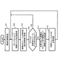
図11は、第2の実施形態に係る組電池システムの管理装置120の通信制御を示すフローチャートである。図中、Sはフローの各ステップを示す。
まず、ステップS1で、管理装置120は、通信周波数を設定する。
ステップS2では、管理装置120は、ブロードキャストで制御コマンドを各蓄電池モジュール100に定期送信する。制御コマンドは、セル電圧や温度、内部抵抗値、残存電荷量、充放電状況、ID、不具合の有無、劣化度合いなどに関する電池情報を計測するための計測指示である。
ステップS3では、管理装置120は、設定周波数で受信するなどの蓄電池モジュール110の応答処理を行う。
ステップS4では、管理装置120は、すべての蓄電池モジュール110から応答があるか否かを判別する。
すべての蓄電池モジュール110から応答がある場合、上記ステップS2に戻ってブロードキャストによる制御コマンドの定期送信を継続する。
すべての蓄電池モジュール110から応答がない場合、ステップS5で管理装置120は、予備周波数があり周波数変更可能か否かを判別する。
予備周波数があり周波数変更が可能な場合、ステップS6で管理装置120は、予備周波数の中から通信周波数を選択し、選択した通信周波数に変更する。通信周波数の変更は、例えば予め決められた周波数を順次使用する。この場合、次に使用する通信周波数は、なるべく離れた周波数帯の通信周波数であることが好ましい。
ステップS7では、管理装置120は、応答がなかった蓄電池モジュール110に対してユニキャストで制御コマンドを再送して上記ステップS2に戻る。FIG. 11 is a flowchart showing communication control of the
First, in step S1, the
In step S <b> 2, the
In step S3, the
In step S <b> 4, the
When there is a response from all the
When there is no response from all the
If there is a spare frequency and the frequency can be changed, in step S6, the
In step S7,
上記ステップS5で周波数変更ができない場合、ステップS8で管理装置120は、エラー処理を行って上記ステップS2に戻る。このエラー処理は、応答がなかった蓄電池モジュール110に対して制御コマンドを送信することができなかったことを出力する。この場合、管理装置120は、後記するように別の蓄電池モジュールを中継して無線通信を行う通信制御に移行するトリガとして用いることができる。また、上位コントローラである蓄電池システムコントローラ20(図1参照)にその旨を通知するようにしてもよい。
このように、本通信制御フローでは、最初の指示はブロードキャストで実施し、届かなかった蓄電池モジュールに対しては周波数を変更してユニキャストで再送する。If the frequency cannot be changed in step S5, the
Thus, in this communication control flow, the first instruction is performed by broadcast, and the storage battery module that has not arrived is retransmitted by unicast with the frequency changed.
図12は、本実施形態に係る組電池システムの管理装置120と各蓄電池モジュール110−1〜110−4間の通信制御を示す制御シーケンス図である。通信周期Tで通信スロット(応答用スロット)#1〜#5、再送スロット#6〜#9、計測スロット#10が繰り返される。
FIG. 12 is a control sequence diagram illustrating communication control between the
組電池システムは、すべての蓄電池モジュール110が同一時間以内に一斉に電池状態を計測し終える必要がある。図12の場合、計測スロット#10の時間内に電池情報を計測しなければならない。計測に同時性が必要な点が一般的な無線通信システムと異なる。
In the assembled battery system, it is necessary for all the
図12に示すように、管理装置120は、通信スロット(応答用スロット)の開始スロット(slot#1)で、すべての蓄電池モジュール110−1〜110−4に対して通信周波数f1で制御コマンドをブロードキャストで送信する。
蓄電池モジュール110−1〜110−4は、通信スロットの開始スロット(slot#1)において、管理装置120からのブロードキャストによる指示を受信する。
蓄電池モジュール110−1〜110−4は、蓄電池モジュールIDの順に管理装置120に通信周波数f1で応答する。As shown in FIG. 12, the
The storage battery modules 110-1 to 110-4 receive the broadcast instruction from the
The storage battery modules 110-1 to 110-4 respond to the
管理装置120は、蓄電池モジュール110−1〜110−4からの応答を受信して、通信成功/通信エラーを判定する。管理装置120は、スロット#2,#3,#5で蓄電池モジュール110−1,100−2,100−4からの応答を受信して通信成功を判断する。しかし、蓄電池モジュール100−3は、通信周波数f1の伝搬特性が劣化しており、ブロードキャストを受信失敗したとする。蓄電池モジュール110−3のみ管理装置120からの指示を受け取っていないため、応答を返さない。
The
管理装置120は、蓄電池モジュール110−3が通信エラーと判断して、応答がなかった蓄電池モジュール110−3に対し再送スロット#6〜#9を用いて制御コマンドを再送する。管理装置120は、通信周波数f1を通信周波数f2に変更し、再送スロット#6で、蓄電池モジュール110−3に対して通信周波数f2で制御コマンドをユニキャストで送信する。
蓄電池モジュール100−3は、f2の伝搬特性についても劣化しており、ユニキャストを受信失敗したとする。蓄電池モジュール110−3は、管理装置120からの指示を受け取っていないため、応答を返さない。The
The storage battery module 100-3 is also deteriorated in the propagation characteristics of f2, and is assumed to have failed to receive unicast. Since the storage battery module 110-3 has not received an instruction from the
管理装置120は、通信周波数f2を通信周波数f3に変更し、再送スロット#8で、蓄電池モジュール110−3に対して通信周波数f3で制御コマンドをユニキャストで送信する。このように、管理装置120は、使用可能な周波数チャネルがある場合、この周波数を用いて、通信失敗した蓄電池モジュールに対して直接再送を行う。
管理装置120は、再送スロット#9で蓄電池モジュール110−3からの応答を受信して、通信周波数f3で通信成功と判定する。管理装置120は、蓄電池モジュール110−3が通信周波数f3で受信可能であることをテーブルデータとして保存し次回の通信制御に使用することができる。なお、管理装置120は、再送スロット#6〜#8をすべてを使っても通信エラーとなった場合、また予備周波数がない場合などは、本通信制御を終了して、後記するように別の蓄電池モジュールを中継して無線通信を行う通信制御に移行するようにしてもよい。The
The
管理装置120は、計測スロット#10で制御コマンドを実行する。計測スロット#10は、制御コマンドの実行用(計測用)のスロットである。組電池システムは、すべての蓄電池モジュール110−1〜110−4が、計測スロット#10の時間内に一斉に電池状態を計測する。制御コマンドで計測されたデータは、次の応答で伝達される。
なお、再送スロットは、複数の蓄電池モジュール分設けてもよい。また、計測スロット#10が先頭にあり、#10,#1,#2,…,#9というフレーム構成でもよい。The
Note that retransmission slots may be provided for a plurality of storage battery modules. Also, the
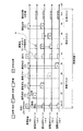
図13は、組電池システム内における管理装置120(Ma)と3台の蓄電池モジュール110−1〜110−3(M1〜M3)の間で時分割多重通信を行う例を示す図である。図中、Mは電池情報の計測、Maは管理装置120、M1は蓄電池モジュール110−1、M2は蓄電池モジュール110−2、M3は蓄電池モジュール110−3である。また、図中のBCはブロードキャスト(Broad cast)、Sは送信(Send)、Rは受信(Receive)、REは受信エラー(Receive error)状態をそれぞれ表している。
FIG. 13 is a diagram illustrating an example in which time division multiplex communication is performed between the management device 120 (Ma) and the three storage battery modules 110-1 to 110-3 (M1 to M3) in the assembled battery system. In the figure, M is measurement of battery information, Ma is a
図13に示すように、管理装置MaとM1〜M3の通信は、時間を一定の間隔で区切ったタイムスロットを元に行われ、1回の収集周期は電池情報の計測、計測指示、応答、及び再送のためのタイムスロットで構成される。 As shown in FIG. 13, the communication between the management devices Ma and M1 to M3 is performed based on a time slot in which time is divided at a constant interval, and one collection cycle includes measurement of battery information, measurement instruction, response, And time slots for retransmission.
図13では、タイムスロット♯1を、計測を実施するための時間として割り当てる。タイムスロット♯2は、計測指示の送信に用いられ、Maから全ての蓄電池モジュールM1〜M3に対して計測指示をブロードキャストで送信する。
計測指示の中には次の収集周期における計測開始タイミング、各タイムスロットに割り当てる通信チャネル、応答用スロットにおける各蓄電池モジュールの応答順序の情報が含まれる。例えば、タイムスロット♯2で送った計測指示により、各蓄電池モジュールM1〜M3は、次の収集周期の計測タイムスロットが♯10であること、及び♯11以降の通信に用いられる通信チャネル、応答順序を認識する。In FIG. 13,
The measurement instruction includes the measurement start timing in the next collection cycle, the communication channel assigned to each time slot, and the response order of each storage battery module in the response slot. For example, according to the measurement instruction sent in the
電池状態の計測は前の計測周期に受け取った計測指示をもとに実施されるため、蓄電池モジュールM1〜M3の最初の応答では最新の計測データがない。このため過去に収集したデータ、予め決められた初期値、又は空のデータのいずれかを応答データとして送るようにする。また、初期のタイムスロットの割り当て、周波数の割り当ては初期値として各蓄電池モジュールM1〜M3に設定されているものとする。 Since the measurement of the battery state is performed based on the measurement instruction received in the previous measurement cycle, there is no latest measurement data in the first response of the storage battery modules M1 to M3. Therefore, data collected in the past, a predetermined initial value, or empty data is sent as response data. In addition, it is assumed that initial time slot allocation and frequency allocation are set to the storage battery modules M1 to M3 as initial values.
ここで、タイムスロット♯2において、蓄電池モジュールM1,M2は、ブロードキャストを正しく受信でき、蓄電池モジュールM3が正しく受信できなかった場合を想定する。計測指示を正しく受信できた蓄電池モジュールM1,M2は、予め定められたそれぞれの応答用スロット♯3,♯4でブロードキャストを受けたときと同じ周波数で最新の計測データを管理装置Maに送信する。しかし、計測指示を正しく受信できなかった蓄電池モジュールM3は、タイムスロット♯5において応答を返さない。管理装置Maは本来♯5で応答が来るはずの蓄電池モジュールM3から応答が返ってこなかったことから、M3との通信に失敗したことを知り、次の再送用スロットにおいて蓄電池モジュールM3への再送を試みる。
Here, it is assumed that in
組電池システム100(図1参照)において、利用可能な周波数チャネルがチャネルch1,ch2,ch3であるとする。ブロードキャストにチャネルch1を使う場合、再送スロットには、チャネルch1以外の周波数が設定される。例えば、図13に示される方式ではブロードキャスト、計測指示、応答にはチャネルch1を用い、再送用のタイムスロット♯6,♯7にはチャネルch2、タイムスロット♯8,♯9にはチャネルch3がそれぞれ割り当てられている。チャネルch1の通信がマルチパスによる電波伝搬環境の劣化によって失敗した場合、再送を行う際に通信チャネルを変えることで電波伝搬の落込みを回避することができる可能性がある。
In the assembled battery system 100 (see FIG. 1), the available frequency channels are assumed to be channels ch1, ch2, and ch3. When channel ch1 is used for broadcasting, a frequency other than channel ch1 is set in the retransmission slot. For example, in the method shown in FIG. 13, channel ch1 is used for broadcast, measurement instruction, and response, channel ch2 is used for retransmission
再送用のタイムスロット♯6において、管理装置Maは、通信できなかった蓄電池モジュールM3宛てに計測指示を再送する。計測指示を正しく受け取った蓄電池モジュールM3は、タイムスロット♯7で応答を返す。全ての蓄電池モジュールM1〜M3から応答が返ってきたことが確認できた場合、余った再送用のスロット♯8,♯9では送受信を行わない。
In the
また、管理装置Maからのブロードキャストが正しく受け取れた場合であって、監視装置Maが各蓄電池モジュールM1〜M3からの応答を正常に受け取れなかった場合にも同様に、監視装置Maは各蓄電池モジュールM1〜M3への再送処理を実施する。再送スロットで管理装置Maが再送処理を実施するかどうかを予め各蓄電池モジュールM1〜M3が知ることはできないため、各蓄電池モジュールM1〜M3は管理装置Maからの計測指示の再送に備えてタイムスロット♯6ではチャネルch2,♯8ではチャネルch3で受信状態になるように、予め設定される。
タイムスロット♯1〜♯9の計測周期を終え、次の計測周期の先頭スロット♯10で各蓄電池モジュールは計測指示に従い同時に計測を行う。以降、この動作を繰り返すことで管理装置Maは、二次電池115(図3及び図4参照)の電池情報を定期的に収集することができる。Similarly, when the broadcast from the management device Ma is correctly received and the monitoring device Ma cannot normally receive the responses from the storage battery modules M1 to M3, the monitoring device Ma is also connected to each storage battery module M1. Perform retransmission processing to M3. Since each storage battery module M1 to M3 cannot know in advance whether or not the management device Ma performs the retransmission processing in the retransmission slot, each storage battery module M1 to M3 is ready to resend the measurement instruction from the management device Ma. In # 6, the channel ch2 and # 8 are set in advance so that the reception state is set in channel ch3.
After the measurement cycle of
なお、計測を実施するための時間、計測指示に割り当てられる時間は複数のタイムスロットにまたがって構成されてもよい。応答用のタイムスロットの数は少なくとも蓄電池モジュールの数以上とし、各蓄電池モジュールの応答順序はブロードキャストで送らずに予め設定することもできる。また再送用のスロットは少なくとも2スロット以上設けられているものとする。 Note that the time for performing the measurement and the time allocated to the measurement instruction may be configured across a plurality of time slots. The number of response time slots is at least equal to or greater than the number of storage battery modules, and the response order of each storage battery module can be set in advance without being sent by broadcast. It is assumed that at least two slots for retransmission are provided.
このように、本実施形態の組電池システム100は、管理装置120が、各蓄電池モジュール110に対して計測指示をブロードキャストで送信するとともに、再送時はユニキャストで送信する。また、蓄電池モジュール110は、計測した電池情報を個別に管理装置に送信する。これにより、組電池システム100は、通信時間を短縮することができ、すべての蓄電池モジュール110−1〜110−4が、計測時間内に一斉に電池状態を計測することができる。
As described above, in the assembled
特に、本実施形態では、管理装置120は、最初の計測指示をブロードキャストで実施し、計測指示が届かなかった蓄電池モジュール110に対してはユニキャストで再送を実施する。このとき、使用可能な別の周波数チャネルがある場合はこの周波数を利用して直接再送を行う。また、管理装置120は、応答受信の期間に蓄電池モジュール110からの応答がない場合、通信に失敗したものと判断し、組電池システム110内で複数の通信周波数を選択できる場合、予め決められた手順に従って通信周波数を変更して該当する蓄電池モジュールに計測指示を再送する。これにより、金属筐体101(組電池システム110)内部にマルチパスが生じて特定の周波数で電波伝搬特性が劣化している場合であっても、計測指示を全体に伝達することができ、通信品質の劣化を回避することができる。その結果、マルチパスが生じる金属筐体101内部でも安定して無線通信を行うことのできる通信方式を実現することができる。
In particular, in the present embodiment, the
(第3の実施形態)
第3の実施形態は、本発明の基本的な考え方で述べた(C)の方法を採る例である。
図14は、第3の実施形態に係る組電池システムの管理装置120の通信制御を示すフローチャートである。図11と同一処理を行うステップには同一ステップ番号を付して説明を省略する。(Third embodiment)
The third embodiment is an example in which the method (C) described in the basic concept of the present invention is employed.
FIG. 14 is a flowchart showing communication control of the
図14において、ステップS4で管理装置120は、すべての蓄電池モジュール110から応答があるか否かを判別する。
すべての蓄電池モジュール110から応答がある場合、ステップS2に戻ってブロードキャストによる制御コマンドの定期送信を継続する。
すべての蓄電池モジュール110から応答がない場合、ステップS11で管理装置120は、応答があった蓄電池モジュール110のうち、適当な一つを中継器として選んで制御コマンドを送信する。管理装置120は、例えばSOCが高い二次電池を有する蓄電池モジュールを中継器として選択することが好ましい。In FIG. 14, the
When there is a response from all of the
When there is no response from all the
図15は、本実施形態に係る組電池システムの管理装置120と各蓄電池モジュール110−1〜110−4間の通信制御を示す制御シーケンス図である。通信周期Tで通信スロット(応答用スロット)#1〜#5、再送スロット#6〜#9、計測スロット#10が繰り返される。図12と同一部分には同一番号を付している。
FIG. 15 is a control sequence diagram illustrating communication control between the
図15に示すように、管理装置120は、通信スロット(応答用スロット)の開始スロット(slot#1)で、すべての蓄電池モジュール110−1〜110−4に対して通信周波数f1で制御コマンドをブロードキャストで送信する。
蓄電池モジュール110−1〜110−4は、通信スロットの開始スロット(slot#1)において、管理装置120からのブロードキャストによる指示を受信する。
蓄電池モジュール110−1〜110−4は、蓄電池モジュールIDの順に管理装置120に通信周波数f1で応答する。As shown in FIG. 15, the
The storage battery modules 110-1 to 110-4 receive the broadcast instruction from the
The storage battery modules 110-1 to 110-4 respond to the
管理装置120は、蓄電池モジュール110−1〜110−4からの応答を受信して、通信成功/通信エラーを判定する。管理装置120は、スロット#2,#3,#5で蓄電池モジュール110−1,100−2,100−4からの応答を受信して通信成功を判断する。しかし、蓄電池モジュール100−3は、管理装置120間の通信周波数f1の伝搬特性が劣化しており、ブロードキャストを受信失敗したとする。蓄電池モジュール110−3のみ管理装置120からの指示を受け取っていないため、応答を返さない。
The
管理装置120は、蓄電池モジュール110−3が通信エラーと判断して、応答があった蓄電池モジュール110−1,110−2,110−4のうち、適当な蓄電池モジュール110−2を中継器として選んで制御コマンドを送信する。管理装置120は、中継器として蓄電池モジュールID順に中継指示してもよいが、例えばSOCが高い二次電池を有する蓄電池モジュール110−2を中継器として選択するとより好ましい。また、蓄電池モジュール110−3との間の位置関係を考慮して決めてもよい。このように管理装置120は、蓄電池モジュール110−3にコマンドを伝達するため、蓄電池モジュール110−2を経由して指示を伝送する。再送時はマルチホップである。
The
中継指示を受けて中継器となった蓄電池モジュール110−2は、応答がなかった蓄電池モジュール110−3に対し再送スロット#7を用いて通信周波数f1で制御コマンドを伝送する。ここで、管理装置120から蓄電池モジュール110−3への通信周波数f1によるブロードキャストは受信失敗しているが、同じ通信周波数f1を用いても蓄電池モジュール110−2と蓄電池モジュール110−3との間では、通信が成功する可能性がある。なお、図15a.に示すように応答があった蓄電池モジュール110−1,110−2,110−4のうち、中継指示がない場合、又は再送スロット#6で再送指示が自分宛でないと判断した蓄電池モジュール110−1,110−4はスリープする。
The storage battery module 110-2 that has become a repeater in response to the relay instruction transmits a control command at the communication frequency f1 using the
蓄電池モジュール110−3は、再送スロット#7において蓄電池モジュール110−2を経由して伝送された制御コマンドを受信し、再送スロット#8において通信周波数f1で蓄電池モジュール110−2に応答を返信する。
蓄電池モジュール110−2は、再送スロット#9において、中継した蓄電池モジュール110−3からの応答を管理装置120に送信する。Storage battery module 110-3 receives the control command transmitted via storage battery module 110-2 in
The storage battery module 110-2 transmits the response from the relayed storage battery module 110-3 to the
管理装置120は、再送スロット#9で蓄電池モジュール110−2を経由して伝送された蓄電池モジュール110−3からの応答を受信して、通信成功と判定する。管理装置120は、蓄電池モジュール110−3が通信周波数f1を用い、かつ蓄電池モジュール110−2を経由して受信可能であることをテーブルデータとして保存し次回の通信制御に使用することができる。なお、管理装置120は、蓄電池モジュール110−2を中継器として用いても通信エラーとなった場合、別の蓄電池モジュールを中継して無線通信を行うようにしてもよい。
The
管理装置120は、計測スロット#10で制御コマンドを実行する。計測スロット#10は、制御コマンドの実行用(計測用)のスロットである。組電池システムは、すべての蓄電池モジュール110−1〜110−4が、計測スロット#10の時間内に一斉に電池状態を計測する。制御コマンドで計測されたデータは、次の応答で伝達される。
The
なお、再送スロットは、複数の蓄電池モジュール分設けてもよい。また、計測スロット#10が先頭にあり、#10,#1,#2,…,#9というフレーム構成でもよい。また、図15に示す指示1,指示2に次のブロードキャストの周波数情報を含ませることで2回目以降、全体の通信周波数が変更可能になる。
Note that retransmission slots may be provided for a plurality of storage battery modules. Also, the
図16は、組電池システム内における管理装置120(Ma)と3台の蓄電池モジュール110−1〜110−3(M1〜M3)の間で時分割多重通信を行う例を示す図である。図13と同一部分には同一番号を付している。 FIG. 16 is a diagram illustrating an example in which time division multiplex communication is performed between the management device 120 (Ma) and the three storage battery modules 110-1 to 110-3 (M1 to M3) in the assembled battery system. The same parts as those in FIG. 13 are denoted by the same reference numerals.
図16に示すように、管理装置Maと蓄電池モジュールM1〜M3の通信は、時間を一定の間隔で区切ったタイムスロットを元に行われ、1回の収集周期は電池情報の計測、計測指示、応答、及び再送のためのタイムスロットで構成される。
図16では、タイムスロット♯1を、計測を実施するための時間として割り当てる。タイムスロット♯2は、計測指示の送信に用いられ、管理装置Maから全ての蓄電池モジュールM1〜M3に対して計測指示をブロードキャストで送信する。As shown in FIG. 16, the communication between the management device Ma and the storage battery modules M1 to M3 is performed based on time slots in which time is divided at regular intervals, and one collection cycle includes measurement of battery information, measurement instructions, It consists of response and retransmission time slots.
In FIG. 16,
タイムスロット♯2において、管理装置Maから送られた計測指示(ブロードキャスト)を蓄電池モジュールM3がマルチパス等によって正しく受信できなかった場合を想定する。蓄電池モジュールM1とM2は、それぞれブロードキャストを受信したときと同じ周波数チャネル1を使ってスロット♯3,♯4で応答を返す。しかし計測指示を正しく受信できなかった蓄電池モジュールM3は、タイムスロット♯5において応答を返さない。管理装置Maは、本来スロット♯5で応答が来るはずの蓄電池モジュールM3から応答が返ってこなかったことから、蓄電池モジュールM3との通信に失敗したと判断し、次に続く再送用スロットで蓄電池モジュールM3への再送を試みる。
Assume that in
ここでシステムの要求等から再送用のスロット♯6〜♯9にも応答用チャネルと同じのチャネル1が割り当てられる場合、再送用のスロットで管理装置Maから蓄電池モジュールM3に対して再送を試みても、マルチパスによる伝搬特性の劣化が同様に生じることから通信が失敗する可能性が大きい。そこで管理装置Maは、直接、蓄電池モジュールM3に対して通信を行わず、応答スロットで応答のあった蓄電池モジュールM1,M2の中から一つを選択(ここでは蓄電池モジュールM1を選択)し、スロット♯6において蓄電池モジュールM1に蓄電池モジュールM3への指示を中継するように要求する。ここで、管理装置Maは、中継を指示する蓄電池モジュールを任意に選択できるものとする。管理装置Maは、SOCが高い二次電池を有する蓄電池モジュールを中継器として選択することが好ましい。
Here, if the
このように、中継することにより伝搬特性の劣化した管理装置Ma−蓄電池モジュールM3の伝搬路を使用することなく、チャネル1を使って蓄電池モジュールM3に計測指示を伝達することができる。ここで、蓄電池モジュールM1のモジュールが中継指示を受けたとすると、蓄電池モジュールM1は、次のタイムスロット♯7において蓄電池モジュールM3に向けて指示を伝送し、指示を受けた蓄電池モジュールM3は、タイムスロット♯8において蓄電池モジュールM1に対して応答を返す。応答を受けたM1がタイムスロット♯9で管理装置Maに蓄電池モジュールM3の応答を伝送することで、全てのモジュールに計測指示を伝達することができる。
Thus, the measurement instruction can be transmitted to the storage battery module M3 using the
このとき、明らかに応答を返さなかった蓄電池モジュールM3以外の蓄電池モジュールは、スロット♯6において管理装置Maから中継を指示される可能性があることから、スロット♯6では受信状態で待機する。応答を返さなかった蓄電池モジュールM3は、自身に対して中継指示が来ることはないと判断し、スロット♯6では受信機を休止させておくことができる。再送用のスロットは、4つのスロットスロット♯6〜♯9を用いて1つの蓄電池モジュールの再送を行うため、4の倍数で複数の再送用スロットを用意しておくことができる。以降、♯10以降は次の計測周期が開始される。
この動作を繰り返すことで周波数チャネルが1つであっても全ての蓄電池モジュールに計測指示を伝達することができる。At this time, the storage battery modules other than the storage battery module M3 that have not clearly returned a response may be instructed to relay from the management device Ma in the
By repeating this operation, a measurement instruction can be transmitted to all the storage battery modules even if there is only one frequency channel.
以上のように、本実施形態の組電池システム100は、管理装置120が、蓄電池モジュールからの応答を受信できなかった場合、応答を受信できた蓄電池モジュールの中から、所定の蓄電池モジュールを中継器として選択し、当該蓄電池モジュールに計測指示及び電池情報の応答を中継させるので、第2の実施形態と同様の効果、すなわち、組電池システム110内部にマルチパスが生じて特定の周波数で電波伝搬特性が劣化している場合であっても、計測指示を全体に伝達することができ、安定して無線通信を行うことができる。この効果に加えて、応答を受信できた別の蓄電池モジュールに計測指示及び電池情報の応答を中継させているので、組電池システム内で通信周波数の変更ができない場合、周波数を変更しても通信できない場合、又は割り当てられた周波数が1つしかない場合であっても、全ての蓄電池モジュールに計測指示を伝達することができるという特有の効果がある。
As described above, when the
(第4の実施形態)
第4の実施形態は、第2及び第3の実施形態の再送方式を組み合わせた例である。本実施形態は、計測指示、応答用スロットの通信チャネルの切り替え機能について説明する。
図17は、第4の実施形態に係る組電池システム内における管理装置120(Ma)と3台の蓄電池モジュール110−1〜110−3(M1〜M3)の間で時分割多重通信を行う例を示す図である。図16と同一部分には同一番号を付している。(Fourth embodiment)
The fourth embodiment is an example in which the retransmission schemes of the second and third embodiments are combined. In this embodiment, the function of switching the communication channel of the measurement instruction and response slot will be described.
FIG. 17 illustrates an example in which time division multiplex communication is performed between the management device 120 (Ma) and the three storage battery modules 110-1 to 110-3 (M1 to M3) in the assembled battery system according to the fourth embodiment. FIG. The same parts as those in FIG. 16 are denoted by the same reference numerals.
図17に示すように、応答スロットで蓄電池モジュールからの応答がないことから、管理装置Maは、当該蓄電池モジュールとの通信が失敗したと判断して再送処理を行うとともに、管理装置Maは、1又は複数回の通信失敗経験から特定のチャネルで当該蓄電池モジュールと安定した通信ができないと判断することができる。このとき、計測指示の中に含まれる次の収集周期の通信チャネルの情報を変更することで、周波数を変更することが可能となる。 As shown in FIG. 17, since there is no response from the storage battery module in the response slot, the management device Ma determines that communication with the storage battery module has failed and performs a retransmission process. Alternatively, it is possible to determine that stable communication with the storage battery module cannot be performed on a specific channel from a plurality of communication failure experiences. At this time, the frequency can be changed by changing the information of the communication channel of the next collection period included in the measurement instruction.
本実施形態は、前記第3の実施形態に示す再送方式を用いる際、通信チャネル変更に特徴がある。
管理装置Maは、タイムスロット♯2においてブロードキャストによる計測指示(ブロードキャスト)を送信する。このブロードキャストを蓄電池モジュールM3のモジュールが受信できなかった場合、蓄電池モジュールM3は、予め割り当てられた応答用タイムスロット♯5で応答を返さない。管理装置Maは、本来タイムスロット♯5で応答が来るはずの蓄電池モジュールM3から応答が返ってこなかったことから、蓄電池モジュールM3との通信に失敗したと判断し、次に続く再送用スロットで、前記第3の実施形態の方法で蓄電池モジュールM3への再送を試みる。また、管理装置Maは、蓄電池モジュールM3との通信が失敗したことから、次の計測周期において通信周波数を変更する指示を出す。これはタイムスロット♯11において、チャネル1を使って計測指示をブロードキャストする際、次のタイムスロット♯20からの計測周期においてチャネル2を用いることを各蓄電池モジュールM1〜M3に伝達することを意味している。通信チャネル2で各蓄電池モジュールとの通信が失敗しなければ、以降はチャネル2を使い続けることができる。The present embodiment is characterized in that the communication channel is changed when the retransmission method shown in the third embodiment is used.
The management device Ma transmits a measurement instruction (broadcast) by broadcast in the
(第5の実施形態)
第5の実施形態は、タイムスロット内で複数の周波数を切り替えて送信、又は受信を行う方式に適用した例である。
図18は、第5の実施形態に係る組電池システム内における管理装置120(Ma)と3台の蓄電池モジュール110−1〜110−3(M1〜M3)の間で時分割多重通信を行う例を示す図である。図18は、タイムスロット内で複数の周波数を切り替えて送信、又は受信を行う方式である。各タイムスロットは複数のサブスロットから構成され、それぞれに周波数チャネルを割り当てて通信することができるものとする。(Fifth embodiment)
The fifth embodiment is an example applied to a method of performing transmission or reception by switching a plurality of frequencies within a time slot.
FIG. 18 is an example in which time division multiplex communication is performed between the management device 120 (Ma) and the three storage battery modules 110-1 to 110-3 (M1 to M3) in the assembled battery system according to the fifth embodiment. FIG. FIG. 18 shows a method of performing transmission or reception by switching a plurality of frequencies within a time slot. Each time slot is composed of a plurality of subslots, each of which can be assigned a frequency channel for communication.
図18に示すように、タイムスロット♯1において、管理装置120(Ma)が周波数を変えながら計測指示をブロードキャストで送信する。つまりタイムスロット♯1のサブスロット1(♯1−1)で管理装置Maはチャネル1で計測指示を送信し、♯1−2ではチャネル2,♯1−3ではチャネル3というように、周波数を切り替えて送信していく。このとき、蓄電池モジュール側でもサブスロットの時間ごとにチャネルを切り替えて受信を行う。但し最初の通信時は、管理装置Maと蓄電池モジュールM1〜M3間の同期がとれていないため、各蓄電池モジュールは予め設定された周波数の中からランダムに周波数を切り替えながら受信することで、ブロードキャストを受けることができる。これにより、いずれかの周波数で電波伝搬特性の劣化が生じて受信できなかったとしても、予め複数の周波数を切り替えて計測指示を伝送することで、いずれかの周波数で計測指示を受信することができる。前記第2乃至第4の実施形態と異なり、計測用のタイムスロットがブロードキャストのすぐ後にあるのは、周波数を変えて計測指示を出すことで、すべての蓄電池モジュールに計測指示を伝えることができるためである。
As shown in FIG. 18, in
計測指示を受け取った各蓄電池モジュールM1〜M3は、タイムスロット♯2で蓄電池情報の計測を行う。タイムスロット♯3は、蓄電池モジュールM1の応答に割り当てられた時間であり、管理装置Maとの間の通信においてサブスロットごとに異なるチャネルが割り当てられている。例えば♯3−1にはチャネル1,♯3−2にはチャネル2,♯3−3にはチャネル3が割り当てられている。蓄電池モジュールM1は、最初にブロードキャストを受信したチャネル1で応答を返し、♯3−1から送信を開始する。一旦チャネル1で通信を開始すると、その通信が終わるか、タイムスロット♯3の時間が終了するまではチャネル1で通信を続けることができる。このため送信データが長い場合など、♯3−2,♯3−3にまたがってチャネル1で通信を行うことが可能となる。
Receiving the measurement instruction, each of the storage battery modules M1 to M3 measures storage battery information at
タイムスロット♯4は、蓄電池モジュールM2の応答に割り当てられた時間である。管理装置Maとの間の通信において、♯4−1はチャネル1,♯4−2はチャネル2,♯4−3がチャネル3というようにそれぞれ別の周波数が割り当てられている。蓄電池モジュールM2はチャネル1で計測指示を受信していることから、♯4−1で応答を返し始める。
タイムスロット♯5は蓄電池モジュールM3の応答に割り当てられた時間であり、♯3,♯4と同様にサブスロットごとに応答用の周波数が割り当てられている。図18では、タイムスロット♯1において、蓄電池モジュールM3がチャネル1、チャネル2での計測指示の受信に失敗し、チャネル3において計測指示を受信している。蓄電池モジュールM3は、管理装置Maとの間の電波伝搬特性がチャネル1、チャネル2で劣化しているものと判断し、チャネル3のサブスロット♯5−3から応答を返し始める。この動作を繰り返すことで、管理装置Maは計測された情報を毎周期ごとに収集することができる。
(第6の実施形態)
第6の実施形態は、ブロードキャストを用いずに各蓄電池モジュールとの通信をポーリングで行う方式に適用した例である。
図19は、第6の実施形態に係る組電池システム内における管理装置120(Ma)と3台の蓄電池モジュール110−1〜110−3(M1〜M3)の間で時分割多重通信を行う例を示す図である。図19は、ブロードキャストを用いずに各蓄電池モジュールとの通信をポーリングで行う方式を示す。(Sixth embodiment)
6th Embodiment is an example applied to the system which performs communication with each storage battery module by polling, without using a broadcast.
FIG. 19 is an example in which time division multiplex communication is performed between the management device 120 (Ma) and the three storage battery modules 110-1 to 110-3 (M1 to M3) in the assembled battery system according to the sixth embodiment. FIG. FIG. 19 shows a method of performing communication with each storage battery module by polling without using broadcast.
図19に示すように、タイムスロット♯1では各蓄電池モジュールM1〜M3の電池情報の計測が行われる。タイムスロット♯2〜♯4では計測指示と応答が各蓄電池モジュールごとに行われる。このとき、通信周波数はチャネル1に固定されている。タイムスロット♯2において、管理装置Maは、蓄電池モジュールM1に対して計測指示を伝達する。計測指示を受け取った蓄電池モジュールM1は、同じタイムスロット♯2の中で計測したデータを返信する。同様に、タイムスロット♯3では管理装置Maと蓄電池モジュールM2が通信を行い、タイムスロット♯4では管理装置Maと蓄電池モジュールM3が通信を行う。タイムスロット♯4において、蓄電池モジュールM3との間の通信が失敗したとき、蓄電池モジュールM3は、管理装置Maに対して応答を返さない。蓄電池モジュールM3からの応答が返ってこなかったことから、管理装置Maは、通信が失敗したものと判断し、タイムスロット♯5,♯6で再送を行う。蓄電池モジュールM3が計測指示を受信し、応答を返した場合であって、管理装置Maが受信失敗した場合も同様に再送処理を行う。
As shown in FIG. 19, in the
タイムスロット♯4において、蓄電池モジュールM3との通信が失敗したとき、管理装置Maは、蓄電池モジュールM3との通信においてチャネル1の電波伝搬特性が劣化しているものと判断し、タイムスロット♯5では通信チャネルを変更して再送を行う。タイムスロット♯5において計測指示を受け取った蓄電池モジュールM3は、同じくタイムスロット♯5の中で応答を返す。タイムスロット♯6では、さらにチャネル3に変更して再送処理を行う。但し、全ての蓄電池モジュールから応答を受け取った場合、残りの再送用スロットでは通信を行わない。
When the communication with the storage battery module M3 fails in the
(第7の実施形態)
第7の実施形態は、ブロードキャストを用いずに各蓄電池モジュールとの通信をポーリングで行う方式に適用した例である。
図20は、第7の実施形態に係る組電池システム内における管理装置120(Ma)と3台の蓄電池モジュール110−1〜110−3(M1〜M3)の間で時分割多重通信を行う例を示す図である。図19と同一部分には同一番号を付している。(Seventh embodiment)
7th Embodiment is an example applied to the system which performs communication with each storage battery module by polling, without using a broadcast.
FIG. 20 illustrates an example in which time division multiplex communication is performed between the management device 120 (Ma) and the three storage battery modules 110-1 to 110-3 (M1 to M3) in the assembled battery system according to the seventh embodiment. FIG. The same parts as those in FIG. 19 are denoted by the same reference numerals.
本実施形態は、前記第6の実施形態と同様に、各蓄電池モジュールとの通信をポーリングで行う方式であって、再送方式が異なるものである。前記第6の実施形態と同様に、タイムスロット♯4において蓄電池モジュールM3との通信に失敗した場合、管理装置Maは、蓄電池モジュールM3との通信においてチャネル1の電波伝搬特性が劣化しているものと判断し、タイムスロット♯5では通信経路を変更して再送を行う。例えばタイムスロット♯5において、管理装置Maは、蓄電池モジュールM2に対して、蓄電池モジュールM3への計測指示を伝送する。
Similar to the sixth embodiment, the present embodiment is a method for performing communication with each storage battery module by polling, and has a different retransmission method. Similar to the sixth embodiment, when communication with the storage battery module M3 fails in the
蓄電池モジュールM3への計測指示を受け取った蓄電池モジュールM2は、管理装置Maと蓄電池モジュールM3との間の中継器の役割を果たし、蓄電池モジュールM3へ計測指示を転送する。蓄電池モジュールM2から計測指示を受け取った蓄電池モジュールM3は、蓄電池モジュールM2に対して応答を返し、蓄電池モジュールM3からの応答を受け取った蓄電池モジュールM2は、管理装置Maに対して蓄電池モジュールM3のデータを転送する。これを繰り返すことで、チャネルの変更を伴わずに全ての蓄電池モジュールに計測指示を伝達し、管理装置Maは定期的に蓄電池情報を収集することが可能となる。なお、再送用のタイムスロットは、他のタイムスロットと同じ時間である必要はなく、再送用の時間を予め任意に設定できる。 Receiving the measurement instruction to the storage battery module M3, the storage battery module M2 plays the role of a relay between the management device Ma and the storage battery module M3, and transfers the measurement instruction to the storage battery module M3. The storage battery module M3 that receives the measurement instruction from the storage battery module M2 returns a response to the storage battery module M2, and the storage battery module M2 that receives the response from the storage battery module M3 sends the data of the storage battery module M3 to the management device Ma. Forward. By repeating this, a measurement instruction is transmitted to all the storage battery modules without changing the channel, and the management device Ma can collect the storage battery information periodically. Note that the time slot for retransmission does not need to be the same time as other time slots, and the time for retransmission can be arbitrarily set in advance.
(第8の実施形態)
第8の実施形態は、ブロードキャスト送信の応用例、及び通信帯域を拡大する例について説明する。
図21は、第8の実施形態に係る組電池システムの管理装置120と各蓄電池モジュール110−1〜110−2間の通信制御を示す制御シーケンス図である。図21は、TDMA制御時の動作例を示す。(Eighth embodiment)
In the eighth embodiment, an application example of broadcast transmission and an example of expanding a communication band will be described.
FIG. 21 is a control sequence diagram illustrating communication control between the
図21に示すように、管理装置120は、ブロードキャスト送信時、単一タイムスロット内で各組電池システムに割り当てられた予備チャネルを使って制御コマンドを送信する。ここで、タイムスロットに余裕があれば複数タイムスロットを使って数回ブロードキャストを送ってもよい。具体的には、図21a.に示すように、複数の周波数f1〜f4で時間T1〜T4を分けて送信する。
ブロードキャスト内部に計測タイミングの情報を入れておくことで、ブロードキャスト後、直ちに同時に計測が可能になる。
計測処理後、蓄電池モジュール110−1は、管理装置120に通信周波数f1で応答送信する。また、蓄電池モジュール110−2は、管理装置120に通信周波数f2で応答送信する。蓄電池モジュール110−2は、予め通信周波数f2で応答する、又は通信周波数f1で受信できなかった場合に通信周波数f2で応答する態様のどちらでもよい。ここで、管理装置120は、受信周波数を一定時間ごとに切り替えことで、通信周波数f1,f2のいずれの通信周波数でも受信可能である。As shown in FIG. 21, at the time of broadcast transmission, the
By including measurement timing information in the broadcast, measurement can be performed immediately after the broadcast.
After the measurement process, the storage battery module 110-1 transmits a response to the
図21b.に示すように、管理装置120は、f1とf2だけで通信できることを学習しているので、次のブロードキャスト送信時には、複数の周波数で時間を分けて送信する場合、周波数f1,f2で時間T1,T2だけで時分割送信する。
FIG. 21b. As shown in FIG. 4, since the
図22は、第8の実施形態に係る組電池システムの管理装置120と各蓄電池モジュール110−1〜110−2間の通信制御を示す制御シーケンス図である。図22は、TDMA制御時の動作例を示す。
図22a.に示すように、蓄電池モジュール110−2が使用する通信チャネルの電波伝搬特性が劣化している場合、管理装置120からのブロードキャストを受信できず、従って計測処理を実施できない。計測指示がないため管理装置120に応答を返さない。FIG. 22 is a control sequence diagram illustrating communication control between the
Figure 22a. As shown in FIG. 2, when the radio wave propagation characteristics of the communication channel used by the storage battery module 110-2 are deteriorated, the broadcast from the
そこで本実施形態では、割り当てられた周波数チャネル内で適応的に帯域を広げて落ち込みを回避する。すなわち、通信できなければ拡散量を増加させる構成を採る。但し、本構成を採るためにはハードウェアの対応が必要となる。
図22b.に示すように、管理装置120は、蓄電池モジュール110−2からの応答がない、又はRSSI(Received Signal Strength Indicator:受信信号強度)値が弱い場合、帯域幅W1では通信不可と判断し、図22c.に示すようにチップレートを変更して拡散量増大する。これにより、帯域を広げて落ち込みを回避することが可能になる。Therefore, in the present embodiment, the bandwidth is adaptively expanded within the allocated frequency channel to avoid a drop. That is, if communication is not possible, a configuration for increasing the diffusion amount is adopted. However, hardware support is required to adopt this configuration.
Figure 22b. As shown in FIG. 22, when there is no response from the storage battery module 110-2 or the RSSI (Received Signal Strength Indicator) value is weak, the
(第9の実施形態)
前記図1に示すように、金属筐体101の内部で無線通信を行う組電池システムであって、金属製の扉102と開閉用の取手103を持つ装置では、扉102の開閉を検出して組電池システム内の通信動作モードを切り替えることができる。例えば、扉102が開いたことを検出して通常の「定期収集モード」から「メンテナンスモード」へと切り替えることができる。「定期収集モード」では通常複数回通信が連続で失敗したことを検出して管理装置120が上位装置、又は金属筐体101に備え付けられたLED等を発光させることで警告を発する。扉102を開けている状態の「メンテナンスモード」ではこの警告を生じないようにする。また、扉102が開いているという情報を警告として伝達することも可能である。さらに管理装置120、前記第4の実施形態に示す周波数変更機能を有している場合、扉102が開いたことを検出したときは、周波数変更を行わないようにすることができる。これにより、扉102が開いても、扉102が閉まっている状態で学習した通信周波数を保持したままにすることができる。(Ninth embodiment)
As shown in FIG. 1, in an assembled battery system that performs wireless communication inside a metal casing 101, an apparatus having a
本実施形態では、電池セルを交換したり保守したりするなどのために組電池システムを覆う金属筐体101を開閉した場合に、無線通信の設定環境が変更されてしまうことを防止することができる。 In the present embodiment, it is possible to prevent the wireless communication setting environment from being changed when the metal casing 101 that covers the assembled battery system is opened and closed in order to replace or maintain the battery cell. it can.
本発明は上記の実施形態例に限定されるものではなく、特許請求の範囲に記載した本発明の要旨を逸脱しない限りにおいて、他の変形例、応用例を含む。
また、上記した実施形態例は本発明をわかりやすく説明するために詳細に説明したものであり、必ずしも説明した全ての構成を備えるものに限定されるものではない。また、ある実施形態例の構成の一部を他の実施形態例の構成に置き換えることが可能であり、また、ある実施形態例の構成に他の実施形態例の構成を加えることも可能である。また、各実施形態例の構成の一部について、他の構成の追加・削除・置換をすることが可能である。The present invention is not limited to the above-described embodiments, and includes other modifications and application examples without departing from the gist of the present invention described in the claims.
Further, the above-described exemplary embodiments have been described in detail for easy understanding of the present invention, and are not necessarily limited to those having all the configurations described. Further, a part of the configuration of an embodiment can be replaced with the configuration of another embodiment, and the configuration of another embodiment can be added to the configuration of an embodiment. . Further, it is possible to add, delete, and replace other configurations for a part of the configuration of each exemplary embodiment.
また、上記の各構成、機能、処理部、処理手段等は、それらの一部又は全部を、例えば集積回路で設計する等によりハードウェアで実現してもよい。また、図1及び図5に示すように、上記の各構成、機能等は、プロセッサがそれぞれの機能を実現するプログラムを解釈し、実行するためのソフトウェアで実現してもよい。各機能を実現するプログラム、テーブル、ファイル等の情報は、メモリや、ハードディスク、SSD(Solid State Drive)等の記録装置、又は、IC(Integrated Circuit)カード、SD(Secure Digital)カード、光ディスク等の記録媒体に保持することができる。また、本明細書において、時系列的な処理を記述する処理ステップは、記載された順序に沿って時系列的に行われる処理はもちろん、必ずしも時系列的に処理されなくとも、並列的あるいは個別に実行される処理(例えば、並列処理あるいはオブジェクトによる処理)をも含むものである。
また、制御線や情報線は説明上必要と考えられるものを示しており、製品上必ずしもすべての制御線や情報線を示しているとは限らない。実際には殆ど全ての構成が相互に接続されていると考えてもよい。Each of the above-described configurations, functions, processing units, processing means, and the like may be realized by hardware by designing a part or all of them with, for example, an integrated circuit. Further, as shown in FIGS. 1 and 5, the above-described configurations, functions, and the like may be realized by software for interpreting and executing a program that realizes each function by the processor. Information such as programs, tables, and files for realizing each function is stored in a memory, a hard disk, a recording device such as an SSD (Solid State Drive), an IC (Integrated Circuit) card, an SD (Secure Digital) card, an optical disk, etc. It can be held on a recording medium. Further, in this specification, the processing steps describing time-series processing are not limited to processing performed in time series according to the described order, but are not necessarily performed in time series, either in parallel or individually. The processing (for example, parallel processing or object processing) is also included.
In addition, the control lines and information lines are those that are considered necessary for the explanation, and not all the control lines and information lines on the product are necessarily shown. Actually, it may be considered that almost all the components are connected to each other.
10,10−1,10−2 蓄電池システム
20 蓄電池システムコントローラ
21,101 金属筐体
22,102 扉
100,100−1〜100−n 組電池システム
110 蓄電池モジュール
111,121 小ケース
115 二次電池
116 セル監視部(電池監視部)
117 制御部(蓄電池モジュール側管理装置)
118 無線通信部
119,123 アンテナ
120 管理装置
122 管理ユニット
10, 10-1, 10-2
117 control unit (storage battery module side management device)
118
Claims (11)
前記金属筐体内に複数収容される各蓄電池モジュールにそれぞれ備わる前記蓄電池モジュール側管理装置と前記金属筐体内において相互に無線通信して、それぞれの前記蓄電池モジュールを管理する管理装置とを具備し、
前記管理装置は、前記各蓄電池モジュール側管理装置に対し、次の計測タイミングを指定する情報を含む計測指示を所定の間隔で送信し、
前記電池監視部に対して、前記計測指示に従って、それぞれの前記蓄電池モジュール間において一斉に蓄電池の電池状態を計測させるように制御し、
前記管理装置は、前記蓄電池モジュール側管理装置からの応答を受信できなかった場合、当該蓄電池モジュール側管理装置に対し、通信周波数を変えて前記計測指示を再送する
ことを特徴とする組電池システム。 A battery monitoring unit that obtains battery information by monitoring the battery state of each storage battery belonging to a storage battery module that includes a plurality of storage batteries connected in series, parallel, or series-parallel. A storage battery module-side management device having a communication unit that wirelessly transmits within a metal housing in which the module is housed,
The storage battery module-side management device provided in each of the storage battery modules housed in the metal casing, and a management device for managing the storage battery modules by wirelessly communicating with each other in the metal casing,
The management device transmits a measurement instruction including information designating the next measurement timing to each storage battery module side management device at a predetermined interval,
For the battery monitoring unit, according to the measurement instruction, control so that the battery state of the storage battery is measured simultaneously between the storage battery modules,
When the management apparatus fails to receive a response from the storage battery module side management apparatus, the management battery retransmits the measurement instruction by changing the communication frequency to the storage battery module side management apparatus.
前記管理装置は、応答を受信できた蓄電池モジュール側管理装置の中から、所定の蓄電池モジュール側管理装置を中継器として選択し、当該蓄電池モジュール側管理装置に前記計測指示及び電池情報の応答を中継させることを特徴とする請求項1記載の組電池システム。 When the management device cannot communicate by changing the communication frequency, or when there is only one allocated frequency,
The management device selects a predetermined storage battery module side management device as a repeater from the storage battery module side management devices that have received the response, and relays the measurement instruction and battery information response to the storage battery module side management device The assembled battery system according to claim 1, wherein:
前記金属筐体内に複数収容される各蓄電池モジュールにそれぞれ備わる前記蓄電池モジュール側管理装置と前記金属筐体内において相互に無線通信して、それぞれの前記蓄電池モジュールを管理する管理装置とを具備し、
前記管理装置は、前記各蓄電池モジュール側管理装置に対し、次の計測タイミングを指定する情報を含む計測指示を所定の間隔で送信し、
前記電池監視部に対して、前記計測指示に従って、それぞれの前記蓄電池モジュール間において一斉に蓄電池の電池状態を計測させるように制御し、
前記管理装置は、前記蓄電池モジュール側管理装置からの応答を受信できなかった場合、応答を受信できた蓄電池モジュール側管理装置の中から、所定の蓄電池モジュール側管理装置を中継器として選択し、当該蓄電池モジュール側管理装置に前記計測指示及び電池情報の応答を中継させることを特徴とする組電池システム。 A battery monitoring unit that obtains battery information by monitoring the battery state of each storage battery belonging to a storage battery module that includes a plurality of storage batteries connected in series, parallel, or series-parallel. A storage battery module-side management device having a communication unit that wirelessly transmits within a metal housing in which the module is housed,
The storage battery module-side management device provided in each of the storage battery modules housed in the metal casing, and a management device for managing the storage battery modules by wirelessly communicating with each other in the metal casing,
The management device transmits a measurement instruction including information designating the next measurement timing to each storage battery module side management device at a predetermined interval,
For the battery monitoring unit, according to the measurement instruction, control so that the battery state of the storage battery is measured simultaneously between the storage battery modules,
When the management device has failed to receive a response from the storage battery module side management device, from among the storage battery module side management device that has received the response, select a predetermined storage battery module side management device as a relay, An assembled battery system, wherein the storage battery module side management device relays a response of the measurement instruction and battery information.
前記金属筐体内に複数収容される各蓄電池モジュールにそれぞれ備わる前記蓄電池モジュール側管理装置と前記金属筐体内において相互に無線通信して、それぞれの前記蓄電池モジュールを管理する管理装置とを具備し、
前記管理装置は、前記各蓄電池モジュール側管理装置に対し、次の計測タイミングを指定する情報を含む計測指示を所定の間隔で送信し、
前記電池監視部に対して、前記計測指示に従って、それぞれの前記蓄電池モジュール間において一斉に蓄電池の電池状態を計測させるように制御し、
前記管理装置は、更に、組電池システム内の電波伝搬状態を取得する取得手段と、
再送時の周波数変更のパターンを記憶する記憶手段と、を備え、
前記管理装置は、前記電波伝搬状態が劣化した前記蓄電池モジュール側管理装置については、予め割り当てられた通信周波数の中で周波数を変更して該当する前記蓄電池モジュールに計測指示を送信することを特徴とする組電池システム。 A battery monitoring unit that obtains battery information by monitoring the battery state of each storage battery belonging to a storage battery module that includes a plurality of storage batteries connected in series, parallel, or series-parallel. A storage battery module-side management device having a communication unit that wirelessly transmits within a metal housing in which the module is housed,
The storage battery module-side management device provided in each of the storage battery modules housed in the metal casing, and a management device for managing the storage battery modules by wirelessly communicating with each other in the metal casing,
The management device transmits a measurement instruction including information designating the next measurement timing to each storage battery module side management device at a predetermined interval,
For the battery monitoring unit, according to the measurement instruction, control so that the battery state of the storage battery is measured simultaneously between the storage battery modules,
The management apparatus further comprises acquisition means for acquiring radio wave propagation status in a battery pack system,
Storage means for storing a frequency change pattern at the time of retransmission,
For the storage battery module side management apparatus in which the radio wave propagation state has deteriorated, the management apparatus changes a frequency in a communication frequency assigned in advance and transmits a measurement instruction to the corresponding storage battery module. Assembled battery system.
前記蓄電池モジュール側管理装置は、計測した前記電池情報を個別に前記管理装置に送信することを特徴とする請求項1乃至請求項5のいずれか一項に記載の組電池システム。 The management device broadcasts the measurement instruction to each storage battery module side management device,
The assembled battery system according to any one of claims 1 to 5, wherein the storage battery module side management device individually transmits the measured battery information to the management device.
計測指示を受け取った前記蓄電池モジュール側管理装置は、一斉に計測した前記電池情報を前記管理装置に送信することを特徴とする請求項1乃至請求項5のいずれか一項に記載の組電池システム。 The management device individually transmits a measurement instruction to each storage battery module side management device,
The assembled battery system according to any one of claims 1 to 5, wherein the storage battery module-side management device that has received the measurement instruction transmits the battery information measured all at once to the management device. .
前記各組電池システムの通信時間、通信周波数、通信空間、又は拡散符号のうちいずれかを前記組電池システムごとに変えることを特徴とする蓄電池システム。 In the storage battery system configured by arranging a plurality of the assembled battery systems according to any one of claims 1 to 8,
Any one of the communication time, the communication frequency, the communication space, and the spreading code of each of the battery pack systems is changed for each battery pack system.
複数の前記蓄電池モジュールと、
複数の前記蓄電池モジュールをまとめた前記組電池システムと、
前記組電池システムをまとめた蓄電池システムとが、この順に階層構造をとり、
前記各階層の無線通信が、時分割、周波数分割、又は拡散符号の多重アクセス制御方式のいずれか一つを組み合わせたことを特徴とする蓄電池システム。 In the storage battery system configured by arranging a plurality of the assembled battery systems according to any one of claims 1 to 8,
A plurality of the storage battery modules;
The assembled battery system in which a plurality of the storage battery modules are combined;
The storage battery system that summarizes the assembled battery system takes a hierarchical structure in this order,
The storage battery system according to claim 1, wherein the wireless communication in each layer is combined with any one of time division, frequency division, and spread code multiple access control.
前記蓄電池モジュール間が時分割、前記組電池システム間が周波数分割、又は前記蓄電池システム間が拡散符号の多重アクセス制御方式により無線通信を行うことを特徴とする蓄電池システム。 In the storage battery system configured by arranging a plurality of the assembled battery systems according to any one of claims 1 to 8,
A storage battery system characterized in that the storage battery modules perform wireless communication by time division, the assembled battery systems by frequency division, or between the storage battery systems by a spread code multiple access control method.
Applications Claiming Priority (1)
| Application Number | Priority Date | Filing Date | Title |
|---|---|---|---|
| PCT/JP2012/084057 WO2014103008A1 (en) | 2012-12-28 | 2012-12-28 | Assembled battery system, storage battery system, and method for monitoring and controlling assembled battery system |
Publications (2)
| Publication Number | Publication Date |
|---|---|
| JPWO2014103008A1 JPWO2014103008A1 (en) | 2017-01-12 |
| JP6228552B2 true JP6228552B2 (en) | 2017-11-08 |
Family
ID=51020159
Family Applications (1)
| Application Number | Title | Priority Date | Filing Date |
|---|---|---|---|
| JP2014553999A Active JP6228552B2 (en) | 2012-12-28 | 2012-12-28 | Battery pack system and storage battery system |
Country Status (4)
| Country | Link |
|---|---|
| US (1) | US20160056510A1 (en) |
| JP (1) | JP6228552B2 (en) |
| CN (1) | CN104885326B (en) |
| WO (1) | WO2014103008A1 (en) |
Cited By (4)
| Publication number | Priority date | Publication date | Assignee | Title |
|---|---|---|---|---|
| DE102021100010A1 (en) | 2020-01-06 | 2021-07-08 | Denso Corporation | Battery pack |
| DE102021100501A1 (en) | 2020-01-15 | 2021-07-15 | Denso Corporation | Battery pack |
| US11955606B2 (en) | 2020-09-21 | 2024-04-09 | Lg Energy Solution, Ltd. | Wireless communication method in battery pack and master BMS providing the method |
| KR102679115B1 (en) * | 2019-07-03 | 2024-06-28 | 주식회사 엘지에너지솔루션 | System and method for managing battery |
Families Citing this family (70)
| Publication number | Priority date | Publication date | Assignee | Title |
|---|---|---|---|---|
| JPH0249513A (en) * | 1988-08-11 | 1990-02-19 | Yanmar Agricult Equip Co Ltd | Combine threshing equipment |
| CN105191051B (en) * | 2013-03-29 | 2018-01-02 | 松下知识产权经营株式会社 | Battery pack |
| US9541432B2 (en) * | 2013-05-17 | 2017-01-10 | The United States Of America As Represented By The Administrator Of The U.S. Environmental Protection Agency | Flow imaging and monitoring for synchronized management of wide area drainage |
| EP3128641B1 (en) * | 2014-04-01 | 2020-01-29 | Kabushiki Kaisha Toshiba | Storage cell system and method for arranging cell module |
| JP6194857B2 (en) * | 2014-06-27 | 2017-09-13 | 日立化成株式会社 | Battery system |
| US10572325B2 (en) * | 2014-11-07 | 2020-02-25 | Hitachi, Ltd. | Power storage management system |
| JP6392088B2 (en) * | 2014-11-13 | 2018-09-19 | 株式会社日立製作所 | Wireless battery system and cell controller and battery controller used therefor |
| JP6421625B2 (en) * | 2015-01-30 | 2018-11-14 | 日立化成株式会社 | Wireless battery system and wireless system |
| JP2016171138A (en) * | 2015-03-11 | 2016-09-23 | 株式会社国際電気通信基礎技術研究所 | Shield structure |
| US9550406B2 (en) | 2015-03-16 | 2017-01-24 | Thunder Power Hong Kong Ltd. | Thermal dissipation system of an electric vehicle |
| US10173687B2 (en) | 2015-03-16 | 2019-01-08 | Wellen Sham | Method for recognizing vehicle driver and determining whether driver can start vehicle |
| US9533551B2 (en) | 2015-03-16 | 2017-01-03 | Thunder Power Hong Kong Ltd. | Electric vehicle thermal management system with series and parallel structure |
| US10703211B2 (en) | 2015-03-16 | 2020-07-07 | Thunder Power New Energy Vehicle Development Company Limited | Battery pack, battery charging station, and charging method |
| US9954260B2 (en) | 2015-03-16 | 2018-04-24 | Thunder Power New Energy Vehicle Development Company Limited | Battery system with heat exchange device |
| US9499067B2 (en) | 2015-03-16 | 2016-11-22 | Thunder Power Hong Kong Ltd. | Power management in electric vehicles |
| EP3840168A1 (en) * | 2015-04-13 | 2021-06-23 | Bedrock Automation Platforms Inc. | Secure power supply for an industrial control system |
| DE102015210038A1 (en) | 2015-06-01 | 2016-12-01 | Robert Bosch Gmbh | Data transmission in a battery system |
| ITUB20156869A1 (en) * | 2015-12-07 | 2017-06-07 | New Cell Top S R L | Battery module |
| CN105429224A (en) * | 2015-12-16 | 2016-03-23 | 常州格力博有限公司 | Electrical system capable of supporting multiple battery packs |
| US9714012B1 (en) | 2016-01-22 | 2017-07-25 | International Business Machines Corporation | Power source element replacement during vehicle operation |
| US9764703B2 (en) | 2016-01-22 | 2017-09-19 | International Business Machines Corporation | Power source element detection and monitoring |
| GB201611532D0 (en) | 2016-07-01 | 2016-08-17 | Dukosi Ltd | Electric batteries |
| US11437840B2 (en) | 2016-08-24 | 2022-09-06 | Hitachi, Ltd. | Battery control system |
| KR20180047511A (en) * | 2016-10-31 | 2018-05-10 | 주식회사 엘지화학 | Energy storage system |
| JP6916983B2 (en) * | 2016-11-01 | 2021-08-11 | 株式会社オートネットワーク技術研究所 | Battery monitoring system for vehicles |
| DE102017204138A1 (en) | 2017-03-13 | 2018-09-13 | Volkswagen Aktiengesellschaft | battery unit |
| JP6591122B2 (en) * | 2017-05-17 | 2019-10-16 | 三菱電機株式会社 | COMMUNICATION DEVICE, COMMUNICATION METHOD, AND COMMUNICATION SYSTEM |
| JP6989221B2 (en) * | 2017-06-23 | 2022-01-05 | ラピスセミコンダクタ株式会社 | Battery monitoring system, signal transmission method and semiconductor device |
| JP6871085B2 (en) * | 2017-06-27 | 2021-05-12 | 積水化学工業株式会社 | Storage battery unit |
| KR102180138B1 (en) | 2017-11-24 | 2020-11-17 | 주식회사 엘지화학 | Wireless battery manamement system and method for protecting a battery back using the same |
| US11536774B2 (en) | 2018-06-14 | 2022-12-27 | Gs Yuasa International Ltd. | Communication device, information processing system, information processing method, and computer program |
| JP6858734B2 (en) * | 2018-08-14 | 2021-04-14 | 矢崎総業株式会社 | Battery monitoring device |
| CN110896157A (en) * | 2018-09-12 | 2020-03-20 | 宁德时代新能源科技股份有限公司 | energy storage system |
| KR102414051B1 (en) | 2018-11-21 | 2022-06-27 | 주식회사 엘지에너지솔루션 | Wireless control system and battery pack including the same |
| KR102414052B1 (en) * | 2018-11-21 | 2022-06-27 | 주식회사 엘지에너지솔루션 | Wireless control system and battery pack including the same |
| KR102520061B1 (en) | 2019-02-01 | 2023-04-07 | 주식회사 엘지에너지솔루션 | Pressing Jig Comprising Magnet And Battery Module Comprising the Same |
| KR102550319B1 (en) * | 2019-02-01 | 2023-07-04 | 주식회사 엘지에너지솔루션 | Battery system and slave battery management system |
| KR102607280B1 (en) * | 2019-02-01 | 2023-11-27 | 주식회사 엘지에너지솔루션 | Battery assembly capable of simultaneous application of mechanical pressing and magnetic pressing to battery cell |
| CN110012534A (en) * | 2019-02-18 | 2019-07-12 | 生迪智慧科技有限公司 | Equipment state synchronous method, device, equipment and computer readable storage medium |
| JP6708318B1 (en) * | 2019-02-27 | 2020-06-10 | 株式会社Gsユアサ | Storage battery monitoring device and storage battery monitoring method |
| WO2020184513A1 (en) * | 2019-03-13 | 2020-09-17 | 株式会社デンソー | Battery monitoring apparatus |
| CN112333844B (en) * | 2019-08-05 | 2025-07-04 | 硅工厂股份有限公司 | Wireless battery management system, node for wireless communication and data transmission method |
| US11265828B2 (en) * | 2019-08-21 | 2022-03-01 | Qualcomm Incorporated | Power allocation for sidelink feedback transmission |
| WO2021053721A1 (en) | 2019-09-17 | 2021-03-25 | 株式会社 東芝 | Storage battery device |
| EP4033637A4 (en) * | 2019-09-17 | 2022-11-09 | Kabushiki Kaisha Toshiba | STORAGE BATTERY DEVICE |
| JP2021086816A (en) * | 2019-11-29 | 2021-06-03 | パナソニックIpマネジメント株式会社 | Battery information management device, battery information management method, and battery information management system |
| KR102785104B1 (en) * | 2019-12-20 | 2025-03-21 | 주식회사 엘지에너지솔루션 | Apparatus and method for diagnosing parallel battery relay |
| JP6977792B2 (en) * | 2020-01-15 | 2021-12-08 | 株式会社デンソー | Battery module |
| JP7375581B2 (en) * | 2020-01-28 | 2023-11-08 | 株式会社デンソー | battery pack |
| DE102020103480B4 (en) | 2020-02-11 | 2025-08-28 | Audi Aktiengesellschaft | Battery system with several self-switching storage units and motor vehicle with this battery system and operating method for the battery system |
| JP7215445B2 (en) * | 2020-02-20 | 2023-01-31 | 株式会社デンソー | battery module |
| CN111405810B (en) * | 2020-03-02 | 2025-01-03 | 浙江杭可科技股份有限公司 | A split independent air duct system for heat dissipation of soft-pack lithium battery capacity division equipment |
| JP7413855B2 (en) * | 2020-03-12 | 2024-01-16 | 株式会社デンソー | In-vehicle equipment |
| CN111370788A (en) * | 2020-04-10 | 2020-07-03 | 天合光能股份有限公司 | Energy storage system BMS wireless networking communication system and method |
| KR102831631B1 (en) * | 2020-06-04 | 2025-07-07 | 주식회사 엘지에너지솔루션 | A battery rack with optimization structure for wireless communication and energy storage device including the same |
| FR3111992B1 (en) | 2020-06-30 | 2022-06-03 | Renault Sas | Method for managing an accumulator battery |
| US11626633B2 (en) * | 2020-08-31 | 2023-04-11 | GM Global Technology Operations LLC | Determination of battery module and sub-pack association in electrical energy storage systems |
| KR102895991B1 (en) * | 2021-02-09 | 2025-12-03 | 주식회사 엘지에너지솔루션 | Apparatus and method for managing battery |
| JP7014320B1 (en) | 2021-03-24 | 2022-02-01 | 株式会社デンソー | Battery management system |
| JP7081710B1 (en) * | 2021-04-21 | 2022-06-07 | 株式会社デンソー | Battery management system |
| JP2023010169A (en) * | 2021-07-09 | 2023-01-20 | 株式会社デンソーテン | Communication apparatus and setting method |
| JP7567722B2 (en) | 2021-08-30 | 2024-10-16 | 株式会社デンソー | Battery Management System |
| JP7711495B2 (en) * | 2021-08-30 | 2025-07-23 | 株式会社デンソー | Battery Management System |
| JP7619211B2 (en) * | 2021-08-30 | 2025-01-22 | 株式会社デンソー | Battery Management System |
| JP7666237B2 (en) * | 2021-08-30 | 2025-04-22 | 株式会社デンソー | Battery management system and battery management method |
| JP7762555B2 (en) | 2021-12-20 | 2025-10-30 | 株式会社Subaru | Battery Pack Monitoring Device |
| CN119968734A (en) * | 2022-09-30 | 2025-05-09 | 株式会社杰士汤浅国际 | Power storage system and protection unit |
| EP4481889A1 (en) * | 2023-06-19 | 2024-12-25 | Dukosi Limited | A communications system for monitoring an electric battery system |
| WO2025033066A1 (en) * | 2023-08-04 | 2025-02-13 | 株式会社ミツトヨ | Measurement information management device, measurement program, measurement method, and measurement system |
| KR20260035658A (en) * | 2024-09-06 | 2026-03-13 | 삼성에스디아이 주식회사 | Communication method for battery management system, and battery management system using the same |
Family Cites Families (17)
| Publication number | Priority date | Publication date | Assignee | Title |
|---|---|---|---|---|
| JP4035913B2 (en) * | 1999-03-18 | 2008-01-23 | 株式会社デンソー | Charged state detection device for assembled battery and vehicle control device using the device |
| US20020028700A1 (en) * | 2000-08-24 | 2002-03-07 | Haruhisa Kato | Power control method in wireless communication device |
| US6424119B1 (en) * | 2001-04-19 | 2002-07-23 | American Power Conversion | Multiple energy storage device controller |
| JP4283833B2 (en) * | 2006-09-06 | 2009-06-24 | 日立ビークルエナジー株式会社 | Secondary battery module |
| JP5088557B2 (en) * | 2008-01-18 | 2012-12-05 | 本田技研工業株式会社 | Capacitor and battery system |
| JP2010142083A (en) * | 2008-12-15 | 2010-06-24 | Toshiba Corp | Battery pack system |
| CA2763425A1 (en) * | 2009-05-25 | 2010-12-02 | Sharp Kabushiki Kaisha | Wireless communication system, wireless communication method, terminal apparatus, and base station apparatus |
| JP5468846B2 (en) * | 2009-08-25 | 2014-04-09 | 矢崎総業株式会社 | Multi-battery battery status monitoring unit |
| JP5331656B2 (en) * | 2009-11-13 | 2013-10-30 | 株式会社日立製作所 | Power supply |
| JP4929389B2 (en) * | 2010-10-14 | 2012-05-09 | 三菱重工業株式会社 | Battery system |
| CN103270666B (en) * | 2010-11-02 | 2018-01-30 | 纳维达斯解决方案有限公司 | Wireless battery Local Area Network for intelligent battery management |
| US8872706B2 (en) * | 2010-11-05 | 2014-10-28 | Apple Inc. | Antenna system with receiver diversity and tunable matching circuit |
| JP5656571B2 (en) * | 2010-11-09 | 2015-01-21 | 株式会社ケーヒン | Communications system |
| JP5673052B2 (en) * | 2010-12-09 | 2015-02-18 | ソニー株式会社 | Power storage device, connection device, power storage system, electronic device, electric vehicle, and power system |
| CN201869368U (en) * | 2010-12-09 | 2011-06-15 | 北京联合大学 | State and energy consumption monitoring system for nodes of sensor network |
| CN102213748B (en) * | 2011-04-11 | 2013-06-19 | 王宜俊 | Battery monitoring device and method |
| CN202121021U (en) * | 2011-04-20 | 2012-01-18 | 上海绿点电子科技有限公司 | Battery monitoring device |
-
2012
- 2012-12-28 CN CN201280078045.XA patent/CN104885326B/en active Active
- 2012-12-28 WO PCT/JP2012/084057 patent/WO2014103008A1/en not_active Ceased
- 2012-12-28 JP JP2014553999A patent/JP6228552B2/en active Active
- 2012-12-28 US US14/655,428 patent/US20160056510A1/en not_active Abandoned
Cited By (8)
| Publication number | Priority date | Publication date | Assignee | Title |
|---|---|---|---|---|
| KR102679115B1 (en) * | 2019-07-03 | 2024-06-28 | 주식회사 엘지에너지솔루션 | System and method for managing battery |
| US12218530B2 (en) | 2019-07-03 | 2025-02-04 | Lg Energy Solution, Ltd. | System and method for managing battery |
| DE102021100010A1 (en) | 2020-01-06 | 2021-07-08 | Denso Corporation | Battery pack |
| DE102021100501A1 (en) | 2020-01-15 | 2021-07-15 | Denso Corporation | Battery pack |
| US11784357B2 (en) | 2020-01-15 | 2023-10-10 | Denso Corporation | Battery pack |
| US12506184B2 (en) | 2020-01-15 | 2025-12-23 | Denso Corporation | Battery pack |
| US11955606B2 (en) | 2020-09-21 | 2024-04-09 | Lg Energy Solution, Ltd. | Wireless communication method in battery pack and master BMS providing the method |
| US12243986B2 (en) | 2020-09-21 | 2025-03-04 | Lg Energy Solution, Ltd. | Wireless communication method in battery pack and master BMS providing the method |
Also Published As
| Publication number | Publication date |
|---|---|
| WO2014103008A1 (en) | 2014-07-03 |
| CN104885326A (en) | 2015-09-02 |
| US20160056510A1 (en) | 2016-02-25 |
| CN104885326B (en) | 2017-06-13 |
| JPWO2014103008A1 (en) | 2017-01-12 |
Similar Documents
| Publication | Publication Date | Title |
|---|---|---|
| JP6228552B2 (en) | Battery pack system and storage battery system | |
| US12342325B2 (en) | Transmission resource configuration method and apparatus | |
| JP4567269B2 (en) | Method and subscriber station for transmission channel assignment in a telecommunications network | |
| JP6514694B2 (en) | Battery system | |
| US10462808B2 (en) | Method for scheduling transmissions in wireless networks | |
| US8315201B2 (en) | Channel synchronization for wireless systems | |
| US9848422B2 (en) | Efficient rendezvous for distributed messages in frequency-hopping communication networks | |
| US8908536B2 (en) | Density-based power outage notification transmission scheduling in frequency-hopping networks | |
| EP2359496B1 (en) | Communication system, communication method, relay station, and computer program | |
| JP2016012954A (en) | Battery system | |
| US5428603A (en) | Synchronous time division multiple access interrogate-respond data communication network | |
| Islam et al. | Performance evaluation of multi-hop LoRaWAN | |
| JP6355040B2 (en) | Communication system and communication apparatus | |
| GB2466550A (en) | Wireless mesh network for inter-component data communications in satellite systems | |
| Ortiz et al. | Multichannel reliability assessment in real world WSNs | |
| US20140078931A1 (en) | Wireless Communication Device, Wireless Communication System, And Wireless Communication Control Method | |
| EP4462805B1 (en) | A battery management system | |
| KR20200047699A (en) | Method and device for determining resource of logical channel, computer storage medium | |
| Deng et al. | A hybrid MAC protocol in data-collection-oriented underwater acoustic sensor networks | |
| KR101136641B1 (en) | Method for allocating a frequency channel to a cluster head | |
| Eraslan | An Overview of Wireless Avionics Intra-Aircraft Communications: Latency and Reliability | |
| KR101575642B1 (en) | Method for Allocating Radio Resource Apparatus System and Cognitive Radio User Terminal Therefor | |
| JP5397434B2 (en) | Wireless access point device and wireless communication system | |
| Delfino et al. | A software radio implementation of centralized MAC protocol for cognitive radio networks | |
| KR101434526B1 (en) | Spatial multiplexing apparatus and method using interference information in a relay repeater of a wireless communication system |
Legal Events
| Date | Code | Title | Description |
|---|---|---|---|
| A521 | Request for written amendment filed |
Free format text: JAPANESE INTERMEDIATE CODE: A523 Effective date: 20161031 |
|
| A131 | Notification of reasons for refusal |
Free format text: JAPANESE INTERMEDIATE CODE: A131 Effective date: 20170307 |
|
| A521 | Request for written amendment filed |
Free format text: JAPANESE INTERMEDIATE CODE: A523 Effective date: 20170425 |
|
| TRDD | Decision of grant or rejection written | ||
| A01 | Written decision to grant a patent or to grant a registration (utility model) |
Free format text: JAPANESE INTERMEDIATE CODE: A01 Effective date: 20170919 |
|
| A61 | First payment of annual fees (during grant procedure) |
Free format text: JAPANESE INTERMEDIATE CODE: A61 Effective date: 20171013 |
|
| R150 | Certificate of patent or registration of utility model |
Ref document number: 6228552 Country of ref document: JP Free format text: JAPANESE INTERMEDIATE CODE: R150 |
|
| R250 | Receipt of annual fees |
Free format text: JAPANESE INTERMEDIATE CODE: R250 |
|
| R250 | Receipt of annual fees |
Free format text: JAPANESE INTERMEDIATE CODE: R250 |
|
| S533 | Written request for registration of change of name |
Free format text: JAPANESE INTERMEDIATE CODE: R313533 |
|
| R350 | Written notification of registration of transfer |
Free format text: JAPANESE INTERMEDIATE CODE: R350 |
|
| R250 | Receipt of annual fees |
Free format text: JAPANESE INTERMEDIATE CODE: R250 |
|
| R250 | Receipt of annual fees |
Free format text: JAPANESE INTERMEDIATE CODE: R250 |
|
| R250 | Receipt of annual fees |
Free format text: JAPANESE INTERMEDIATE CODE: R250 |
|
| R250 | Receipt of annual fees |
Free format text: JAPANESE INTERMEDIATE CODE: R250 |