JP6228524B2 - Continuous casting method - Google Patents
Continuous casting method Download PDFInfo
- Publication number
- JP6228524B2 JP6228524B2 JP2014192187A JP2014192187A JP6228524B2 JP 6228524 B2 JP6228524 B2 JP 6228524B2 JP 2014192187 A JP2014192187 A JP 2014192187A JP 2014192187 A JP2014192187 A JP 2014192187A JP 6228524 B2 JP6228524 B2 JP 6228524B2
- Authority
- JP
- Japan
- Prior art keywords
- tundish
- stainless steel
- molten
- molten metal
- continuous casting
- Prior art date
- Legal status (The legal status is an assumption and is not a legal conclusion. Google has not performed a legal analysis and makes no representation as to the accuracy of the status listed.)
- Active
Links
Images


Classifications
-
- B—PERFORMING OPERATIONS; TRANSPORTING
- B22—CASTING; POWDER METALLURGY
- B22D—CASTING OF METALS; CASTING OF OTHER SUBSTANCES BY THE SAME PROCESSES OR DEVICES
- B22D11/00—Continuous casting of metals, i.e. casting in indefinite lengths
- B22D11/10—Supplying or treating molten metal
- B22D11/106—Shielding the molten jet
-
- B—PERFORMING OPERATIONS; TRANSPORTING
- B22—CASTING; POWDER METALLURGY
- B22D—CASTING OF METALS; CASTING OF OTHER SUBSTANCES BY THE SAME PROCESSES OR DEVICES
- B22D11/00—Continuous casting of metals, i.e. casting in indefinite lengths
- B22D11/001—Continuous casting of metals, i.e. casting in indefinite lengths of specific alloys
- B22D11/002—Stainless steels
-
- B—PERFORMING OPERATIONS; TRANSPORTING
- B22—CASTING; POWDER METALLURGY
- B22D—CASTING OF METALS; CASTING OF OTHER SUBSTANCES BY THE SAME PROCESSES OR DEVICES
- B22D11/00—Continuous casting of metals, i.e. casting in indefinite lengths
-
- B—PERFORMING OPERATIONS; TRANSPORTING
- B22—CASTING; POWDER METALLURGY
- B22D—CASTING OF METALS; CASTING OF OTHER SUBSTANCES BY THE SAME PROCESSES OR DEVICES
- B22D11/00—Continuous casting of metals, i.e. casting in indefinite lengths
- B22D11/04—Continuous casting of metals, i.e. casting in indefinite lengths into open-ended moulds
- B22D11/041—Continuous casting of metals, i.e. casting in indefinite lengths into open-ended moulds for vertical casting
-
- B—PERFORMING OPERATIONS; TRANSPORTING
- B22—CASTING; POWDER METALLURGY
- B22D—CASTING OF METALS; CASTING OF OTHER SUBSTANCES BY THE SAME PROCESSES OR DEVICES
- B22D11/00—Continuous casting of metals, i.e. casting in indefinite lengths
- B22D11/10—Supplying or treating molten metal
-
- B—PERFORMING OPERATIONS; TRANSPORTING
- B22—CASTING; POWDER METALLURGY
- B22D—CASTING OF METALS; CASTING OF OTHER SUBSTANCES BY THE SAME PROCESSES OR DEVICES
- B22D11/00—Continuous casting of metals, i.e. casting in indefinite lengths
- B22D11/10—Supplying or treating molten metal
- B22D11/108—Feeding additives, powders, or the like
-
- B—PERFORMING OPERATIONS; TRANSPORTING
- B22—CASTING; POWDER METALLURGY
- B22D—CASTING OF METALS; CASTING OF OTHER SUBSTANCES BY THE SAME PROCESSES OR DEVICES
- B22D11/00—Continuous casting of metals, i.e. casting in indefinite lengths
- B22D11/10—Supplying or treating molten metal
- B22D11/11—Treating the molten metal
- B22D11/111—Treating the molten metal by using protecting powders
-
- B—PERFORMING OPERATIONS; TRANSPORTING
- B22—CASTING; POWDER METALLURGY
- B22D—CASTING OF METALS; CASTING OF OTHER SUBSTANCES BY THE SAME PROCESSES OR DEVICES
- B22D11/00—Continuous casting of metals, i.e. casting in indefinite lengths
- B22D11/10—Supplying or treating molten metal
- B22D11/11—Treating the molten metal
- B22D11/116—Refining the metal
- B22D11/117—Refining the metal by treating with gases
-
- B—PERFORMING OPERATIONS; TRANSPORTING
- B22—CASTING; POWDER METALLURGY
- B22D—CASTING OF METALS; CASTING OF OTHER SUBSTANCES BY THE SAME PROCESSES OR DEVICES
- B22D11/00—Continuous casting of metals, i.e. casting in indefinite lengths
- B22D11/16—Controlling or regulating processes or operations
Landscapes
- Engineering & Computer Science (AREA)
- Mechanical Engineering (AREA)
- Continuous Casting (AREA)
- Treatment Of Steel In Its Molten State (AREA)
- Casting Support Devices, Ladles, And Melt Control Thereby (AREA)
Description
この発明は、連続鋳造方法に関する。 The present invention relates to a continuous casting method.
金属の一種であるステンレス鋼の製造工程では、電気炉で原料を溶解して溶銑が生成され、生成された溶銑は、転炉、真空脱ガス装置でステンレス鋼の特性を低下させる炭素を除去する脱炭処理等を含む精錬が行われて溶鋼とされ、その後、溶鋼が連続鋳造されることによって凝固して板状のスラブ等を形成する。なお、精錬工程では、溶鋼の最終的な成分の調整が行われる。 In the manufacturing process of stainless steel, which is a kind of metal, molten iron is produced by melting raw materials in an electric furnace, and the produced molten iron removes carbon that deteriorates the properties of stainless steel in a converter and a vacuum degassing device. Refining including decarburization is performed to form molten steel, and then the molten steel is continuously cast to solidify to form a plate-like slab or the like. In the refining process, the final components of the molten steel are adjusted.
連続鋳造工程では、溶鋼は、取鍋からタンディッシュに注がれ、さらに、タンディッシュから連続鋳造用の鋳型の中に注がれて鋳造される。このとき、最終的な成分調整後の溶鋼が、大気中の窒素又は酸素と反応して窒素の含有量を増大させること又は酸化されるのを防ぐために、タンディッシュ内における取鍋から鋳型に至る溶鋼の周囲には、溶鋼表面を大気から遮断するシールガスが供給される。
例えば、特許文献1には、シールガスとしてアルゴンガスを使用する連鋳(連続鋳造)スラブの製造方法が記載されている。
In the continuous casting process, molten steel is poured from a ladle into a tundish, and further poured from a tundish into a casting mold for continuous casting. At this time, in order to prevent the molten steel after final component adjustment from reacting with nitrogen or oxygen in the atmosphere to increase the content of nitrogen or being oxidized, the ladle from the ladle in the tundish reaches the mold. A seal gas that blocks the surface of the molten steel from the atmosphere is supplied around the molten steel.
For example,
特許文献1の製造方法のように、シールガスとしてアルゴンガスを使用すると、溶鋼内に取り込まれたアルゴンガスが気泡として残り、連鋳スラブの表面及びその近傍において、アルゴンガスによる気泡欠陥、つまり表面欠陥が生じやすい。そして、連鋳スラブに表面欠陥が生じると、所要の品質を確保するために表面を削り取る必要があり、コストが増大するという問題がある。このため、本発明者は、不活性ガスとして、溶鋼内で気泡として残存しにくい窒素をシールガスとして使用し、さらに、窒素の溶鋼への溶け込みを防ぐために溶鋼表面にパウダー層を形成して窒素と溶鋼とを遮断する技術を開発した。
When argon gas is used as the sealing gas as in the manufacturing method of
また、ステンレス鋼には、酸化しやすいチタン等を成分として含む鋼種がある。このような鋼種のステンレス鋼の精錬工程では、脱炭素用に吹精される酸素とチタンとの反応を防ぐために、酸素とさらに反応しやすいアルミニウムを添加して溶鋼中の酸素を除去するアルミニウム脱酸が行われる。アルミニウムは、酸素と反応してアルミナとなることによって、溶鋼中の酸素を取り除く。しかしながら、アルミナの融点は2020℃と高いため、溶鋼中のアルミナは、溶鋼の温度が低下する鋳造工程で析出し、例えばタンディッシュから鋳型へのノズルの内壁に付着・堆積して閉塞させることがある。このため、本発明者は、タンディッシュ内の溶鋼にCa含有物を添加して、アルミナをより低融点のアルミン酸カルシウムに変化させてノズルの閉塞を防止する対策をとってきた。 In addition, stainless steel includes a steel type containing titanium, which is easily oxidized, as a component. In the refining process of stainless steel of such steel grade, in order to prevent the reaction between oxygen blown for decarbonization and titanium, aluminum that is more reactive with oxygen is added to remove oxygen in the molten steel. Acid is done. Aluminum reacts with oxygen to become alumina, thereby removing oxygen in the molten steel. However, since the melting point of alumina is as high as 2020 ° C., the alumina in the molten steel is precipitated in the casting process in which the temperature of the molten steel is lowered, and may adhere and deposit on the inner wall of the nozzle from the tundish to the mold, for example. is there. For this reason, the present inventor has taken measures to prevent nozzle clogging by adding a Ca-containing material to molten steel in a tundish to change alumina to a calcium aluminate having a lower melting point.
しかしながら、タンディッシュ内においてCa含有物を添加する際にシールガスである窒素が溶鋼中に混入し、混入した窒素が溶鋼中の成分と接触して反応することで生成される生成物が、スラブの表面近傍に介在物として析出して表面欠陥を生じさせるという問題が生じた。 However, when a Ca-containing material is added in the tundish, nitrogen, which is a sealing gas, is mixed into the molten steel, and the product produced by the mixed nitrogen contacting and reacting with the components in the molten steel is a slab. There arises a problem that surface defects are caused by precipitation as inclusions in the vicinity of the surface of the steel.
この発明はこのような問題点を解決するためになされたものであり、アルミニウム脱酸が行われた溶鋼(溶融金属)の鋳造時におけるタンディッシュから鋳型へのノズルの閉塞を防止しつつ、溶鋼を鋳造したスラブ(金属片)における表面欠陥の低減を図る連続鋳造方法を提供することを目的とする。 The present invention has been made to solve such problems, while preventing the nozzle from clogging from the tundish to the mold during casting of molten steel (molten metal) that has been subjected to aluminum deoxidation. An object of the present invention is to provide a continuous casting method for reducing surface defects in a slab (metal piece) obtained by casting a metal.
上記の課題を解決するために、この発明に係る連続鋳造方法は、取鍋内のアルミニウム脱酸が行われた溶融金属をタンディッシュ内に注入し、タンディッシュ内の溶融金属を鋳型に連続注入して金属片を鋳造する連続鋳造方法において、取鍋内の溶融金属をタンディッシュ内に注入するための注入ノズルとして、タンディッシュ内に延びるロングノズルを取鍋に設けるロングノズル設置ステップと、ロングノズルの注出口をタンディッシュ内に注入された溶融金属に浸漬させつつ、ロングノズルを通じてタンディッシュ内に溶融金属を注入すると共に、タンディッシュ内の溶融金属を鋳型に注入する鋳造ステップと、タンディッシュ内の溶融金属の表面を覆うようにタンディッシュパウダーを散布する散布ステップと、タンディッシュパウダーを散布した溶融金属の周囲にシールガスとして窒素ガスを供給するシールガス供給ステップと、タンディッシュ内に貯留されている状態以外の状態の溶融金属にカルシウム含有物を添加する添加ステップとを含む。 In order to solve the above-mentioned problems, the continuous casting method according to the present invention injects molten metal, which has been deoxidized in a ladle, into a tundish, and continuously injects the molten metal in the tundish into a mold. In the continuous casting method for casting metal pieces, a long nozzle installation step in which a long nozzle extending in the tundish is provided in the pan as an injection nozzle for injecting molten metal in the ladle into the tundish, and a long A casting step in which the molten metal is injected into the tundish through the long nozzle while the nozzle outlet is immersed in the molten metal injected into the tundish, and the molten metal in the tundish is injected into the mold, and the tundish Spraying step for spraying tundish powder to cover the surface of the molten metal inside, and tundish powder The includes a seal gas supply step of supplying a nitrogen gas as a seal gas around the sprayed molten metal, and an additive adding a calcium-containing substance to the molten metal in the state other than the state which is stored in the tundish.
溶融金属はチタンを成分として含有してもよい。
カルシウム含有物を、溶融金属の鋳造前の工程である精錬工程で添加してもよい。
カルシウム含有物は、タンディッシュから鋳型に溶融金属を注入するためのノズルの内壁面に含まれてもよい。
タンディッシュパウダーを散布する前では、シールガスとしてアルゴンガスをタンディッシュ内の溶融金属の周囲に供給してもよい。
The molten metal may contain titanium as a component.
You may add a calcium containing material in the refining process which is a process before casting of molten metal.
The calcium-containing material may be included in the inner wall surface of the nozzle for injecting molten metal from the tundish into the mold.
Before spraying the tundish powder, argon gas may be supplied as a sealing gas around the molten metal in the tundish.
この発明に係る連続鋳造方法によれば、アルミニウム脱酸が行われた溶融金属の鋳造時におけるタンディッシュから鋳型へのノズルの閉塞を防止しつつ、溶融金属を鋳造した金属片のおける表面欠陥を低減することが可能になる。 According to the continuous casting method of the present invention, the surface defect in the metal piece cast from the molten metal is prevented while preventing the nozzle from clogging from the tundish to the mold at the time of casting the molten metal subjected to aluminum deoxidation. It becomes possible to reduce.
実施の形態1.
以下、この発明の実施の形態1に係る連続鋳造方法について添付図面に基づいて説明する。なお、以下の実施の形態では、二次精錬工程でアルミニウム脱酸を必要とするステンレス鋼の1つであるチタン(Ti)を成分として含有するステンレス鋼の連続鋳造方法について説明する。
Hereinafter, a continuous casting method according to
まず、ステンレス鋼の製造は、溶解工程、一次精錬工程、二次精錬工程、及び鋳造工程がこの順で実施されて行われる。
溶解工程では、ステンレス製鋼用の原料となるスクラップ及び合金などが電気炉で溶解されて溶銑が生成され、生成された溶銑は転炉に注銑される。さらに、一次精錬工程では、転炉内の溶銑に酸素を吹精することによって含有されている炭素を除去する粗脱炭処理が行われ、それによりステンレス溶鋼と酸化物及び不純物を含むスラグとが生成する。また、一次精錬工程では、ステンレス溶鋼の成分が分析され、目的とする成分に近づけるために合金を投入する成分の粗調整も実施される。さらに、一次精錬工程で生成したステンレス溶鋼は、取鍋に出鋼されて二次精錬工程に移される。
First, stainless steel is manufactured by performing a melting process, a primary refining process, a secondary refining process, and a casting process in this order.
In the melting step, scraps and alloys as raw materials for stainless steel are melted in an electric furnace to generate hot metal, and the generated hot metal is poured into a converter. Furthermore, in the primary refining process, a rough decarburization process is performed to remove carbon contained by blowing oxygen into the molten iron in the converter, thereby producing a molten stainless steel and slag containing oxides and impurities. Generate. Further, in the primary refining process, the components of the molten stainless steel are analyzed, and the rough adjustment of the components to which the alloy is added is performed in order to approximate the target components. Furthermore, the molten stainless steel produced in the primary refining process is delivered to the ladle and transferred to the secondary refining process.
図1を参照すると、二次精錬工程では、ステンレス溶鋼1は、取鍋2と共に真空酸素脱炭装置(真空脱ガス装置、VODとも呼ばれ、以下、VODと称す)10内に入れられ、仕上げ脱炭処理、最終的な脱硫、酸素・窒素・水素などの脱ガス処理、及び介在物の除去等がなされる。そして、ステンレス溶鋼1が上述の処理を受けることによって、製品としての目的の特性を有するステンレス溶鋼が生成する。なお、二次精錬工程では、ステンレス溶鋼1の成分が分析され、目的とする成分にさらに近づけるために合金を投入する、成分の最終的な調整も実施される。ここで、ステンレス溶鋼1は、溶融金属を構成している。
Referring to FIG. 1, in the secondary refining process, the molten
VOD10は、内部に取鍋2を入れることができる真空槽11を有している。取鍋2には、一次精錬工程において酸化物等の不純物を含むスラグが除去された後のステンレス溶鋼1が入れられている。真空槽11は、内部の空気を外部に排出するための排気管11aを有しており、排気管11aは図示しない真空ポンプ及び蒸気エジェクターに接続されるように構成されている。
また、VOD10は、真空槽11の外部から内部に延び且つ真空槽11内で取鍋2の上部からステンレス溶鋼1に酸素を吹精するように構成された酸素ガスランス12を有している。ステンレス溶鋼1では、含有炭素は、吹精される酸素と反応して一酸化炭素に酸化されることによって除去される。そして、真空槽11内を減圧することによって、含有炭素の上記反応が促進される。
The
The
さらに、VOD10は、取鍋2の底部からステンレス溶鋼1に攪拌用のアルゴン(Ar)ガスを送るためのアルゴンガスランス13と、上方から取鍋2内のステンレス溶鋼1に合金を投入するための合金ホッパ14とを、真空槽11に有している。
真空槽11内のステンレス溶鋼1には、酸素と反応しやすいTiが成分として添加される。このため、Tiを添加する前に、ステンレス溶鋼1に含有される未反応の酸素を除去するために、脱酸剤(脱酸素剤)として、Tiよりも酸素との反応性が高いアルミニウム(Al)含有合金が、合金ホッパ14から添加されるように構成されている。Al含有合金中のAlは、酸素と反応してアルミナ(Al2O3)となり、Al2O3の多くは、Arガスによる攪拌によって凝集してスラグ内に吸収される。なお、ステンレス溶鋼1に含有する窒素及び水素は、真空槽11内を減圧することによってステンレス溶鋼1から除去される。
Furthermore, the
Ti, which easily reacts with oxygen, is added to the molten
鋳造工程では、取鍋2が真空槽11から取り出されて連続鋳造装置(CC)100にセットされる。取鍋2内のステンレス溶鋼1は、連続鋳造装置100に注ぎ込まれ、さらに連続鋳造装置100が備える鋳型105によって、例えば金属片としてスラブ状のステンレス鋼片1cに鋳造される。鋳造されたステンレス鋼片1cは、次の図示しない圧延工程において、熱間圧延又は冷間圧延され熱間圧延鋼帯又は冷間圧延鋼帯とされる。
In the casting process, the
さらに、連続鋳造装置(CC)100の構成の詳細を説明する。
図2を参照すると、連続鋳造装置100は、取鍋2から送られるステンレス溶鋼1を一時的に貯留しつつ鋳型105に送るための容器であるタンディッシュ101を有している。タンディッシュ101は、上部が開放した本体101bと、本体101bの開放した上部を閉鎖し外部と遮断する上蓋101cと、本体101bの底部から延びる浸漬ノズル101dとを有している。そして、タンディッシュ101では、本体101b及び上蓋101cによってこれらの内部に閉鎖された内部空間101aが形成される。浸漬ノズル101dは、入口101eで本体101bの底部から内部空間101a内に開口している。
Furthermore, the detail of a structure of the continuous casting apparatus (CC) 100 is demonstrated.
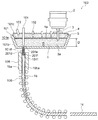
Referring to FIG. 2, the
また、取鍋2は、タンディッシュ101の上方にセットされ、取鍋2の底部には、上蓋101cを貫通して内部空間101a内に延びる注入ノズルとしてのロングノズル3が接続されている。そして、ロングノズル3の下方先端の注出口3aが、内部空間101aで開口している。また、ロングノズル3と上蓋101cとの間は、シールされ気密性が保たれている。
The
上蓋101cには、複数のガス供給ノズル102が設けられている。ガス供給ノズル102は、図示しないガスの供給源に接続されており、内部空間101a内に上方から下方に向かって所定のガスを送出する。また、ロングノズル3は、この所定のガスがその内部に供給されるように構成されている。
A plurality of
さらに、上蓋101cには、内部空間101a内に上方から下方に向かってタンディッシュパウダー(以下、TDパウダーと呼ぶ)5を送出するためのパウダノズル103が設けられている。パウダノズル103は、図示しないTDパウダー供給源に接続されている。なお、TDパウダー5は、合成スラグ剤等からなり、ステンレス溶鋼1の表面を覆うことによって、ステンレス溶鋼1の表面の酸化防止作用、ステンレス溶鋼1の保温作用、ステンレス溶鋼1の介在物を溶解吸収する作用等を、ステンレス溶鋼1に対して奏する。
Further, the
また、浸漬ノズル101dの上方には、上下方向に移動可能な棒状のストッパ104が設けられており、ストッパ104は、上蓋101cを貫通してタンディッシュ101の内部空間101aから外部にわたって延在している。
ストッパ104は、下方に移動することによってその先端で浸漬ノズル101dの入口101eを閉鎖することができる他、入口101eを閉鎖した状態から上方に引き上げられることによって、引き上げ量に応じて入口101eの開口面積を調節し、タンディッシュ101内のステンレス溶鋼1を浸漬ノズル101d内に流入させると共に流入量を制御することができるように構成されている。また、ストッパ104と上蓋101cとの間は、シールされ気密性が保たれている。
Further, a bar-
The
また、タンディッシュ101の底部から外部に突出する浸漬ノズル101dの先端101fは、下方の鋳型105の貫通穴105a内に延在し、その側方で開口している。
貫通穴105aは、矩形断面を有し上下に鋳型105を貫通している。貫通穴105aは、その内壁面が図示しない一次冷却機構によって水冷されるように構成され、内部のステンレス溶鋼1を冷却して凝固させ所定の断面の鋳片1bを形成する。
さらに、鋳型105の貫通穴105aの下方には、鋳型105によって形成された鋳片1bを下方に引き出して移送するためのロール106が間隔をあけて複数設けられている。また、ロール106の間には、鋳片1bに対して散水して冷却するための図示しない二次冷却機構が設けられている。
Further, the
The through
Further, below the through
次に、本実施の形態1に係る連続鋳造方法による連続鋳造装置100及びその周辺の動作を説明する。
図1及び図2をあわせて参照すると、一次精錬後、転炉から取鍋2に移されたステンレス溶鋼1は、取鍋2に入れられた状態でVOD10の真空槽11内に設置される。
Next, the operation of the
Referring to FIGS. 1 and 2 together, the molten
真空槽11内では、取鍋2内のステンレス溶鋼1は、アルゴンガスランス13から供給されるArガスによって攪拌を受けると共に、排気管11aに接続された真空ポンプ及び蒸気エジェクターの作用によって減圧作用を受ける。減圧作用によって、ステンレス溶鋼1は、含有する窒素及び水素を放出してその含有量を低下させる。さらに、ステンレス溶鋼1は、酸素ガスランス12から酸素が吹精されることによって、含有する炭素を酸素と反応させてその含有量を低下させる。また、酸素との反応性が高いTiが成分として添加されるステンレス溶鋼1には、合金ホッパ14から、Tiよりも酸素との反応性が高い脱酸剤としてのAl含有合金が添加され、Al含有合金がステンレス溶鋼1を脱酸した後にTiが添加される。また、ステンレス溶鋼1の成分を構成する成分調整用の合金等も添加される。Al含有合金中のAlは、ステンレス溶鋼1中の酸素と反応してアルミナ(Al2O3)となり、Al2O3の多くはスラグ中に吸収され、一部がステンレス溶鋼1中に残る。このステンレス溶鋼1中のAl2O3は、前述のとおりタンディッシュ101から鋳型105への浸漬ノズル101dの内壁に付着して閉塞させるため、Al2O3をより低融点のアルミン酸カルシウムに変化させて浸漬ノズル101dの閉塞を防止することを目的に、フェロシリコンタイプの合金であるフェロシリカルシウム(FeSiCa)合金及び金属カルシウムの少なくとも1つがステンレス溶鋼1に添加される。また、ステンレス溶鋼1には、硫黄の含有量を低下させるために脱硫も実施される。
ここで、FeSiCa合金及び金属カルシウムは、カルシウム含有物を構成している。
In the
Here, the FeSiCa alloy and metallic calcium constitute a calcium-containing material.
上述のような不純物の除去及び成分調整が完了した(つまり二次精錬が完了した)ステンレス溶鋼1は、取鍋2と共に真空槽11から連続鋳造装置100に移される。
図2及び図3をあわせて参照すると、取鍋2は、タンディッシュ101の上方に設置される。さらに、取鍋2の底部にはロングノズル3が取り付けられ、ロングノズル3における注出口3aを有する先端がタンディッシュ101の内部空間101aに延びている。このとき、ストッパ104は、浸漬ノズル101dの入口101eを閉鎖している。
The molten
Referring to FIGS. 2 and 3 together, the
次に、ガス供給ノズル102からタンディッシュ101の内部空間101a内に、シールガス4として不活性ガスであるArガス4aが噴射されると共に、ロングノズル3の内部にもArガス4aが供給される。これによって、タンディッシュ101の内部空間101a及びロングノズル3内に存在していた不純物を含む空気が、タンディッシュ101の外部に押し出され、内部空間101a及びロングノズル3内はArガス4aで満たされる。つまり、取鍋2からタンディッシュ101の内部空間101aが、Arガス4aで満たされる。
Next, an
その後、取鍋2に設けられた図示しないバルブが開放され、取鍋2内のステンレス溶鋼1が、重力の作用によってロングノズル3内を流下し、タンディッシュ101の内部空間101a内に流入する。つまり、タンディッシュ101内は、図3の工程Aに示す状態となる。
このとき、流入したステンレス溶鋼1は、内部空間101aに充満するArガス4aによって周囲がシールされ空気と接触しないため、空気中に含まれ且つステンレス溶鋼1への溶解性を有する窒素(N2)のステンレス溶鋼1への溶け込みによるN2成分の増加が抑制される。これにより、窒素成分(N)とステンレス溶鋼1に成分として含有されるTiとが接触して反応することによるTiNの生成が抑えられる。なお、TiNは、クラスター化してステンレス溶鋼1中で大型介在物(例えば、230μmの径程度)として存在するようになる。しかしながら、TiNによる大型介在物の発生が抑えられるため、冷却されて固化したステンレス溶鋼1内において、TiNが大型介在物として析出することが抑えられる。
Thereafter, a valve (not shown) provided in the
At this time, the flowing stainless
また、タンディッシュ101内では、ロングノズル3の注出口3aから流下するステンレス溶鋼1が溜まっているステンレス溶鋼1の表面1aをたたき込むことによって、少量であるがArガス4aがステンレス溶鋼1に巻き込まれて混入する。しかしながら、Arガス4aは、ステンレス溶鋼1と反応を起こしたりしない。
Further, in the
そして、タンディッシュ101内では、次々に流入するステンレス溶鋼1によって、その表面1aが上昇する。上昇する表面1aがロングノズル3の注出口3aの近傍となると、注出口3aから流下するステンレス溶鋼1による表面1aのたたき込みが小さくなり周囲の気体の巻き込み量も少なくなるため、パウダノズル103からステンレス溶鋼1の表面1aに向かって、TDパウダー5が散布される。TDパウダー5は、表面1a上の全体を覆うように散布される。
And in the
TDパウダー5の散布後、ガス供給ノズル102からは、Arガス4aに換えて、不活性ガスである窒素(N2)ガス4bが噴射される。これにより、タンディッシュ101の内部空間101a内では、Arガス4aが外部に押し出され、TDパウダー5とタンディッシュ101の上蓋101cとの間の領域が、N2ガス4bで満たされる。
After the
このとき、ステンレス溶鋼1の表面1a上に層状に堆積したTDパウダー5が、ステンレス溶鋼1の表面1aとN2ガス4bとの接触を遮断し、N2ガス4bのステンレス溶鋼1への溶け込みを防ぐ。これにより、ステンレス溶鋼1に成分として含有されるTiと窒素成分(N)との接触が抑制されてTiNの生成が抑制されるため、ステンレス溶鋼1中におけるTiNによる大型介在物の発生が抑えられ、冷却されて固化したステンレス溶鋼1内においてもTiNが大型介在物として析出することが抑えられる。
At this time, the
また、二次精錬工程では、脱酸処理で発生したAl2O3の一部がスラグに吸収されずにステンレス溶鋼1中に残留する。Al2O3は、融点が2020℃と高いため、ステンレス溶鋼1中で析出してクラスター化し、固化後のステンレス溶鋼1中でも大型介在物として存在するようになる。さらに、Al2O3は、ステンレス溶鋼1中で析出することによって、浸漬ノズル101dの内側及びその近傍に付着・堆積し浸漬ノズル101dを閉塞させることもある。
In the secondary refining process, part of Al 2 O 3 generated by the deoxidation treatment remains in the
しかしながら、ステンレス溶鋼1中には、二次精錬工程でFeSiCa合金及び金属カルシウムの少なくとも1つが添加されており、これらFeSiCa合金及び金属カルシウムは、Al2O3に対してアルミン酸カルシウム(12CaO・7Al2O3)に変化させる反応を起こす。12CaO・7Al2O3は、Al2O3の融点よりも大幅に低い1400℃の融点を有しており、ステンレス溶鋼1中で溶解して分散している。よって、12CaO・7Al2O3は、ステンレス溶鋼1において、Al2O3のように大型介在物として析出して存在するようなことがなく、さらに、浸漬ノズル101dの内側及びその近傍に付着・堆積してこれを閉塞させるということもない。
However, at least one of FeSiCa alloy and metallic calcium is added to the molten
従って、FeSiCa合金及び金属カルシウムの少なくとも1つを添加することによって、ステンレス溶鋼1中に残留していたAl2O3が析出した場合においても、12CaO・7Al2O3となり溶解して分散される。さらに、FeSiCa合金及び金属カルシウムの少なくとも1つの添加は、タンディッシュ101内にあるステンレス溶鋼1に対して行われないため、ステンレス溶鋼1を覆っているTDパウダー5の層を乱すことがない。これにより、乱れたTDパウダー5の層からN2ガス4bがステンレス溶鋼1に溶け込んでステンレス溶鋼1中のTiと反応するようなことが防がれる。つまり、TDパウダー5の層が乱れることによるTiNの生成が防がれる。
なお、ステンレス溶鋼1のSi含有量が低く規制されている場合は、カルシウム含有物質としてFeSiCa合金を使用するとSi含有量が規制値を外れる恐れがあるため、金属カルシウム及び後述するドロマイトグラファイト層が設けられたタンディッシュ101の浸漬ノズルの少なくとも一方を使用することが好ましい。
Therefore, even when Al 2 O 3 remaining in the molten
In addition, when the Si content of the molten
また、タンディッシュ101の内部空間101a内では、上昇する表面1aがロングノズル3の注出口3aをステンレス溶鋼1に浸漬させ、さらに内部空間101aにおけるステンレス溶鋼1の深さが所定深さDとなると、ストッパ104が上昇される。それにより、内部空間101a内のステンレス溶鋼1が、浸漬ノズル101d内を通って鋳型105の貫通穴105a内に流入し、鋳造が開始する。また、同時に、取鍋2内のステンレス溶鋼1は、ロングノズル3を通って内部空間101aに継続して注出され、内部空間101aには新たなステンレス溶鋼1が補充される。このとき、タンディッシュ101内は、図3の工程Bに示すような状態となる。
鋳造中、タンディッシュ101では、ロングノズル3の注出口3aをステンレス溶鋼1に浸漬させつつ、ステンレス溶鋼1が所定深さDの近傍の深さを維持し、ステンレス溶鋼1の表面1aがほぼ一定の位置になるように、浸漬ノズル101dからのステンレス溶鋼1の流出量及びロングノズル3を通じたステンレス溶鋼1の流入量が調節される。
Further, in the
During casting, in the
なお、内部空間101aにおけるステンレス溶鋼1の深さが所定深さDのとき、ロングノズル3は、注出口3aがステンレス溶鋼1の表面1aから約100〜150mmの深さとなるように、ステンレス溶鋼1に貫入していることが好ましい。上記の深さよりも深くロングノズル3が貫入すると、内部空間101aに溜まっているステンレス溶鋼1の内圧による抵抗によって、注出口3aからのステンレス溶鋼1の注出が困難になる。一方、上記の深さよりも浅くロングノズル3が貫入すると、鋳造時に所定の位置付近に維持するように制御されるステンレス溶鋼1の表面1aが変動して注出口3aが露出することがあり、この場合、注出されたステンレス溶鋼1が表面1aをたたき込み、N2ガス4bを巻き込み混入させる可能性があるためである。
When the depth of the molten
また、鋳型105の貫通穴105a内に流入したステンレス溶鋼1は、貫通穴105aを流通する過程で図示しない一次冷却機構によって冷却され、貫通穴105aの内壁面側を凝固させて凝固シェル1baを形成する。なお、貫通穴105aの内壁面には、浸漬ノズル101dの先端101f側からモールドパウダーが供給される。モールドパウダーは、ステンレス溶鋼1の表面でスラグ溶融化する、貫通穴105a内でのステンレス溶鋼1の表面の酸化を防止する、鋳型105と凝固シェル1baとの間を潤滑する、貫通穴105a内でのステンレス溶鋼1の表面を保温する等の役割を果たす。
The molten
凝固シェル1baとその内部の未凝固のステンレス溶鋼1とによって鋳片1bが形成され、鋳片1bは、ロール106によって両側から挟まれて下方に向かって引き出される。引き出された鋳片1bは、ロール106の同士の間を通って送られる過程で、図示しない二次冷却機構によって散水冷却され、内部のステンレス溶鋼1を完全に凝固させる。これにより、鋳片1bがロール106によって鋳型105から引き出されつつ、新たな鋳片1bが鋳型105内で形成されることで、鋳型105からロール106の延在方向の全体にわたって連続する鋳片1bが形成される。さらに、ロール106により送り出された鋳片1bが切断されることによって、スラブ状のステンレス鋼片1cが形成される。
A
そして、ストッパ104には、鋳型105の貫通穴105a内でのステンレス溶鋼1の表面が一定高さとなるように、浸漬ノズル101dの入口101eの開放面積を調節する制御がなされる。これによって、ステンレス溶鋼1の流入量が制御される。さらに、入口101eからのステンレス溶鋼1の流出量と同等になるように、取鍋2からのロングノズル3を通じたステンレス溶鋼1の流入量が調節される。これにより、タンディッシュ101の内部空間101a内におけるステンレス溶鋼1の表面1aは、ステンレス溶鋼1の深さが所定深さDの近傍を維持する状態で、鉛直方向にほぼ一定の位置を維持するように制御される。このとき、ロングノズル3は、その先端の注出口3aをステンレス溶鋼1に浸漬させている。そして、上述のように、タンディッシュ101内において、注出口3aをステンレス溶鋼1に浸漬させつつ、ステンレス溶鋼1の表面1aの鉛直方向の位置をほぼ一定に維持した鋳造状態を、定常状態と呼ぶ。
The
よって、定常状態で鋳造が行われている間、ロングノズル3から流入するステンレス溶鋼1による表面1a及びTDパウダー5のたたき込みが生じないため、N2ガス4bは、TDパウダー5によってステンレス溶鋼1から遮断された状態を維持する。これにより、N2ガス4bのステンレス溶鋼1への溶け込みが防がれる。
Therefore, since the
また、取鍋2内のステンレス溶鋼1が無くなると、取鍋2からロングノズル3が取り外され、ロングノズル3をタンディッシュ101に残した状態で、ステンレス溶鋼1を含む別の取鍋2に取り替えられる。取り替えられた取鍋2には、再びロングノズル3が接続される。また、この取鍋2の交換作業中も鋳造作業は継続して実施され、このため、タンディッシュ101の内部空間101aにおけるステンレス溶鋼1の表面1aが下降する。この取鍋2の交換作業中も、N2ガス4bの内部空間101aへの供給は継続される。そして、タンディッシュ101内は、図3の工程Cに示すような状態となる。
Further, when the molten
なお、取鍋2の交換作業中、内部空間101aにおいてステンレス溶鋼1の表面1aがロングノズル3の注出口3aよりも下方とならないように、ストッパ104によって浸漬ノズル101dの入口101eの開口面積を調節し、ステンレス溶鋼1の流出量、つまり鋳造速度が制御される。上述のように複数の取鍋2内のステンレス溶鋼1を連続して鋳造することによって、鋳片1bでは、取鍋2の取り替え時に起因する継ぎ目をなくすことができる。さらに、取鍋2が変わる毎に鋳造の初期等で鋳片1bの品質が変化することも低減される。そして、1つの取鍋2毎に鋳造を終了する場合に必要であった工程であるタンディッシュ101にステンレス溶鋼1を溜めて鋳造を開始するまでの工程の省略が可能となる。
During the replacement operation of the
さらに、鋳造が進行して交換した取鍋2内のステンレス溶鋼1が無くなり鋳造を終了する場合、取鍋2及びロングノズル3が取り除かれ、タンディッシュ101内は、図3の工程Dに示すような状態となる。このとき、ステンレス溶鋼1の新たな流下がなくたたき込み等による表面1a及びTDパウダー5の乱れが生じないため、鋳造終了まで、N2ガス4bのステンレス溶鋼1への溶け込みが防がれる。
Further, when the casting is completed and the molten
また、ロングノズル3の注出口3aが内部空間101a内のステンレス溶鋼1に浸漬する前(図3の工程A参照)においても、注出口3aとタンディッシュ101の本体101bの底部との距離が短いこと、注出口3aとステンレス溶鋼1の表面1aとの距離が短いこと、及び、ステンレス溶鋼1による表面1aのたたき込みが注出口3aの浸漬までの短時間に限られることによって、ステンレス溶鋼1への空気及びArガス4aの巻き込みによる混入が低減している。
Further, even before the
なお、ステンレス溶鋼1による表面1aのたたき込みが発生する状態のときにArガスの代わりにシールガスとしてN2ガス4bを使用する、或いは、表面1aにTDパウダー5を散布してシールガスとしてN2ガス4bを使用すると、N2ガス4bがステンレス溶鋼1に過度に溶解してその成分を製品として不適合なものにすると共にTiNによる多量の介在物を生じさせる可能性がある。このため、ロングノズル3の注出口3aが浸漬するまでの鋳造初期に内部空間101aに溜められたステンレス溶鋼1から鋳造されたステンレス鋼片1cの全てを廃棄する必要が生じる可能性がある。しかしながら、鋳造初期にArガス4aを使用することによって、ステンレス溶鋼1の成分を変化させずに所要の範囲に収めることができると共にTiNの発生を防ぐことができる。また、二次精錬工程で生成したAl2O3は、FeSiCa合金及び金属カルシウムの少なくとも1つによって12CaO・7Al2O3に変えられてステンレス溶鋼1に溶解している。よって、鋳造初期の僅かな空気又はArガス4aが混入したステンレス溶鋼1から鋳造されたステンレス鋼片1cは、大型介在物を含まず且つ所要の成分構成を有しているため、混入したArガス4aにより発生する気泡を除去するための表面切削がなされた後、製品として使用することができる。
In addition, when the
また、鋳造初期の後から鋳造終了までの鋳造時間の大部分を占める、鋳造初期以外の時期に鋳造されたステンレス鋼片1cは、鋳造初期に混入した空気及びArガス4aの影響を受けなくなっており、TDパウダー5によってN2ガス4bの混入が防がれてもいる。このため、鋳造初期以外の時期に鋳造されたステンレス鋼片1cは、二次精錬後の状態から窒素含有量を増加させず、混入する気体の気泡化による表面欠陥の発生も防いでいる。
Further, the
さらに、TDパウダー5によってN2ガス4bからステンレス溶鋼1が遮断されるため、ステンレス溶鋼1ではTiNの生成量が大きく抑えられる。さらに、二次精錬工程で生成したAl2O3は、FeSiCa合金及び金属カルシウムの少なくとも1つによって12CaO・7Al2O3に変えられてステンレス溶鋼1に溶解している。
よって、鋳造初期以外の時期に鋳造されたステンレス鋼片1cは、大型介在物及び気泡による表面欠陥の発生が大きく抑えられ、製品としてそのまま使用することができる。
Further, since the molten
Therefore, the
実施の形態2.
この発明の実施の形態2に係る連続鋳造方法では、実施の形態1に係る連続鋳造方法における二次精錬工程でのステンレス溶鋼1へのFeSiCa合金及び金属カルシウムの添加を行わず、タンディッシュ101の浸漬ノズルの内壁面にこれを覆うドロマイトグラファイト層を形成するようにしたものである。
なお、実施の形態2において、前出した図における参照符号と同一の符号は、同一または同様な構成要素であるので、その詳細な説明は省略する。
In the continuous casting method according to
In the second embodiment, the same reference numerals as those in the previous drawings are the same or similar components, and thus detailed description thereof is omitted.
図4を参照すると、連続鋳造装置100のタンディッシュ101の本体101bの底部からは、実施の形態1と同様にして、浸漬ノズル101dが、鋳型105の貫通穴105a内に延びている。さらに、浸漬ノズル101dの内壁面及び先端101fの内壁面の全体はそれぞれ、ドロマイトグラファイトからなる内側層201d及び201fで覆われている。そして、内側層201dは、ストッパ104が嵌る入口201eを形成している。
Referring to FIG. 4, an
ドロマイトグラファイトは、成分として、MgO(酸化マグネシウム)、CaO(酸化カルシウム)及びC(炭素)を含む。ドロマイトグラファイトの成分構成の一例として、MgO:24.0質量%、CaO:39.0質量%、C:35.0質量%からなるものがある。そして、ドロマイトグラファイトは、下記の式(1)に示すように反応して、Al2O3を低融点の12CaO・7Al2O3に変える。
7Al2O3+12CaO→12CaO・7Al2O3 式(1)
よって、ドロマイトグラファイトは、実施の形態1でステンレス溶鋼1に添加したFeSiCa合金及び金属カルシウムと同様の作用を奏する。
ここで、内側層201d及び201fのドロマイトグラファイトは、Ca含有物を構成している。
Dolomite graphite contains MgO (magnesium oxide), CaO (calcium oxide) and C (carbon) as components. As an example of the component constitution of dolomite graphite, there is one composed of MgO: 24.0% by mass, CaO: 39.0% by mass, and C: 35.0% by mass. And dolomite graphite reacts as shown in the following formula (1) to change Al 2 O 3 to 12CaO · 7Al 2 O 3 having a low melting point.
7Al 2 O 3 + 12CaO → 12CaO · 7Al 2 O 3 formula (1)
Therefore, dolomite graphite has the same effect as the FeSiCa alloy and metallic calcium added to the molten
Here, the dolomite graphite of the
このため、鋳造中、浸漬ノズル101d内に流入するステンレス溶鋼1では、含有されるAl2O3は12CaO・7Al2O3に変化し、ステンレス溶鋼1内に溶解して分散する。よって、浸漬ノズル101d及びその周辺でAl2O3が付着・堆積することが抑制されると共に、鋳造後のステンレス鋼片1cにおいてAl2O3が大型介在物として析出することによる表面欠陥の発生が大きく抑えられる。
さらに、ドロマイトグラファイトは、タンディッシュ101内にあるステンレス溶鋼1に対して添加されるわけではないため、ステンレス溶鋼1を覆っているTDパウダー5の層を乱すことがない。これにより、乱れたTDパウダー5を介してN2ガス4bがステンレス溶鋼1に溶け込むことが防がれ、TiNが大型介在物として析出することによる表面欠陥の発生が大きく抑えられる。
For this reason, in the molten
Further, since dolomite graphite is not added to the molten
また、この発明の実施の形態2に係る連続鋳造方法に関わるその他の構成及び動作は、実施の形態1と同様であるため、説明を省略する。
さらに、実施の形態2における連続鋳造方法によれば、上記実施の形態1の連続鋳造方法と同様な効果が得られる。
また、実施の形態2におけるドロマイトグラファイトからなる内側層201d及び201fを、実施の形態1における浸漬ノズル101dに適用してもよい。これにより、ステンレス溶鋼1中のAl2O3がより確実に12CaO・7Al2O3に変えられる。
In addition, since other configurations and operations related to the continuous casting method according to the second embodiment of the present invention are the same as those in the first embodiment, description thereof will be omitted.
Furthermore, according to the continuous casting method in the second embodiment, the same effect as the continuous casting method in the first embodiment can be obtained.
Further, the
(実施例)
以下、実施の形態1及び2に係る連続鋳造方法を用いてステンレス鋼片を鋳造した実施例を説明する。
Ti添加フェライト系ステンレス鋼について、実施の形態1及び2の連続鋳造方法を用いてステンレス鋼片であるスラブを鋳造した実施例1〜5と、比較例1とを比較した。
(Example)
Hereinafter, examples in which stainless steel pieces are cast using the continuous casting method according to the first and second embodiments will be described.
About Ti addition ferritic stainless steel, Examples 1-5 which cast the slab which is a stainless steel piece using the continuous casting method of
実施例1〜3は、実施の形態1の連続鋳造方法に対応し、二次精錬工程でFeSiCa合金が添加される例である。
実施例4は、実施の形態1の連続鋳造方法に対応し、二次精錬工程で金属カルシウムが添加される例である。
実施例5は、実施の形態2の連続鋳造方法に対応し、タンディッシュの浸漬ノズルの内壁面にドロマイトグラファイトからなる層が設けられる例である。なお、実施例5におけるステンレス鋼の化学成分構成の規格は、実施例4におけるステンレス鋼の化学成分構成の規格と同じである。
Examples 1 to 3 correspond to the continuous casting method of the first embodiment and are examples in which FeSiCa alloys are added in the secondary refining process.
Example 4 corresponds to the continuous casting method of
Example 5 corresponds to the continuous casting method of
比較例1は、実施の形態1の連続鋳造方法において、Ca含有物として、二次精錬工程でFeSiCa合金及び金属カルシウムを添加せず、タンディッシュ内にあるTDパウダーで覆われたステンレス溶鋼に対してCaSiワイヤを投入した例である。 Comparative Example 1 is a continuous casting method according to the first embodiment, in which the Ca-containing material is not added with FeSiCa alloy and metallic calcium in the secondary refining process, and is a stainless steel covered with TD powder in the tundish. In this example, a CaSi wire is introduced.
また、以下の検出結果は、実施例では、鋳造初期を除く定常状態で鋳造されたスラブからサンプリングしたものであり、比較例では、鋳造開始からの実施例のサンプリング時期と同時期に鋳造されたスラブからサンプリングしたものである。
実施例及び比較例のそれぞれについて、ステンレス鋼の化学成分構成の規格を表1に示し、シールガスの種類、注入ノズルの種類、TDパウダーの使用の有無、及びステンレス溶鋼に加えられるCa含有物からなる鋳造条件を表2に示す。
In addition, the following detection results were sampled from a slab cast in a steady state except for the initial casting in the example, and in the comparative example, the casting was performed at the same time as the sampling time of the example from the start of casting. Sampled from slab.
About each of an Example and a comparative example, the specification of the chemical component structure of stainless steel is shown in Table 1, from the kind of seal gas, the kind of injection nozzle, the presence or absence of the use of TD powder, and the Ca-containing material added to the stainless steel molten steel Table 2 shows the casting conditions.

さらに、以下の表3において、製造した多数のスラブから気泡欠陥が検出されたスラブ数の割合と、上記スラブから介在物による欠陥が検出されたスラブ数の割合とについて、実施例1〜5を総合した結果と比較例1の結果との間で比較した。そして、表3では、実施例1〜5については、スラブを表面研削しない場合と表面研削した場合の結果を示し、比較例1については、表面研削しない場合の結果を示している。なお、表面研削した場合については、スラブの表面を片面2mm厚(両面で4mm厚)で研削を行った。 Furthermore, in Table 3 below, Examples 1 to 5 were used for the ratio of the number of slabs in which bubble defects were detected from a number of manufactured slabs and the ratio of the number of slabs in which defects due to inclusions were detected from the slabs. A comparison was made between the combined results and the results of Comparative Example 1. In Table 3, for Examples 1 to 5, the results when the slab is not surface ground and when the surface is ground are shown, and for Comparative Example 1, the results when the surface is not ground are shown. In the case of surface grinding, the surface of the slab was ground with a thickness of 2 mm on one side (4 mm thickness on both sides).
表3の結果から、実施例1〜5は、スラブを表面研削しない場合でも、気泡欠陥の発生率が0であり、介在物による欠陥の発生率も低く抑えられている。さらに、実施例1〜5は、スラブ表面を研削すれば、欠陥の発生率も0となり、非常に優秀な品質を有する。 From the results of Table 3, in Examples 1 to 5, even when the slab is not surface ground, the incidence of bubble defects is 0, and the incidence of defects due to inclusions is also kept low. Further, in Examples 1 to 5, if the surface of the slab is ground, the defect occurrence rate becomes 0, and the quality is extremely excellent.
また、図5は、実施例1〜5で、スラブの鋳造時におけるタンディッシュの浸漬ノズルでの析出物の堆積状況を比較したものである。図5では、横軸は、ステンレス鋼を連続して鋳造した長さを示し、縦軸は、ストッパ(図2のストッパ104参照)の偏差を示す。なお、ストッパ偏差とは、タンディッシュの浸漬ノズルの入口(図1の入口101e及び図4の入口201e参照)を閉鎖したときのストッパの上下方向の位置ずれのことである。つまり、浸漬ノズルの入口に析出物の付着がない場合、ストッパ偏差は0である。一方、浸漬ノズルの入口に析出物が堆積すると、閉鎖時のストッパの位置が上方にずれるが、このずれ量がストッパ偏差となる。そして、ストッパの偏差が5mmに達すると、浸漬ノズルの入口が析出物で閉塞すると想定する。
FIG. 5 is a comparison of the deposition state of precipitates with a tundish immersion nozzle during slab casting in Examples 1-5. In FIG. 5, the horizontal axis indicates the length of continuously cast stainless steel, and the vertical axis indicates the deviation of the stopper (see the
図5において、実施例1〜3では、鋳造長が延びてもストッパ偏差は1mm前後で互いに同様に推移し、浸漬ノズルの入口の閉塞は発生しない。実施例4では、鋳造長が延びてもストッパ偏差は3mm前後で同様に推移し、浸漬ノズルの入口の閉塞は発生しない。実施例5では、鋳造長が延びてもストッパ偏差は2.5mm程度までにしか達さず、浸漬ノズルの入口の閉塞は発生しない。 In FIG. 5, in Examples 1 to 3, even if the casting length is extended, the stopper deviation changes in the same manner at around 1 mm, and the inlet of the immersion nozzle is not blocked. In Example 4, even if the casting length is extended, the stopper deviation similarly changes around 3 mm, and the inlet of the immersion nozzle is not blocked. In Example 5, even if the casting length is extended, the stopper deviation only reaches about 2.5 mm, and the inlet of the immersion nozzle is not blocked.
なお、上記鋼種以外にも18Cr-1Mo-0.5Ti系及び22Cr-1.2Mo-Nb-Ti系のステンレス鋼などのTiを成分として含む鋼種について本発明を適用し、実施例1〜5に示すような表面欠陥抑止効果及び浸漬ノズル閉塞防止が得られることを確認した。
また、実施の形態1及び2に係る連続鋳造方法は、Tiを成分として含むステンレス鋼について説明したが、二次精錬工程でアルミニウム脱酸を必要とし且つNbを成分として含むステンレス鋼にも適用すると効果的である。
また、実施の形態1及び2に係る連続鋳造方法は、ステンレス鋼の製造に適用されていたが、他の金属の製造に適用してもよい。
また、実施の形態1及び2に係る連続鋳造方法におけるタンディッシュ101での制御は、連続鋳造に適用されていたが、他の鋳造方法に適用してもよい。
In addition to the above steel types, the present invention is applied to steel types containing Ti as a component, such as 18Cr-1Mo-0.5Ti and 22Cr-1.2Mo-Nb-Ti stainless steels. It was confirmed that the surface defect inhibiting effect and the immersion nozzle blockage prevention as shown can be obtained.
In addition, the continuous casting method according to
Moreover, although the continuous casting method which concerns on
Further, the control in the
1 ステンレス溶鋼(溶融金属)、1c ステンレス鋼片(金属片)、2 取鍋、3 ロングノズル(注入ノズル)、3a 注出口、4a アルゴン(Ar)ガス(シールガス)、4b 窒素(N2)ガス(シールガス)、5 タンディッシュパウダー、100 連続鋳造装置、101 タンディッシュ、105 鋳型。 1 stainless molten steel (molten metal), 1c stainless steel pieces (metal piece), 2 ladle, 3 long nozzle (injection nozzle), 3a spout, 4a argon (Ar) gas (sealing gas), 4b nitrogen (N 2) Gas (seal gas), 5 tundish powder, 100 continuous casting apparatus, 101 tundish, 105 mold.
Claims (5)
前記取鍋内の前記溶融金属を前記タンディッシュ内に注入するための注入ノズルとして、前記タンディッシュ内に延びるロングノズルを前記取鍋に設けるロングノズル設置ステップと、
前記ロングノズルの注出口を前記タンディッシュ内に注入された前記溶融金属に浸漬させつつ、前記ロングノズルを通じて前記タンディッシュ内に前記溶融金属を注入すると共に、前記タンディッシュ内の前記溶融金属を前記鋳型に注入する鋳造ステップと、
前記タンディッシュ内の前記溶融金属の表面を覆うようにタンディッシュパウダーを散布する散布ステップと、
前記タンディッシュパウダーを散布した前記溶融金属の周囲にシールガスとして窒素ガスを供給するシールガス供給ステップと、
前記タンディッシュ内に貯留されている状態以外の状態の前記溶融金属にカルシウム含有物を添加する添加ステップと
を含む連続鋳造方法。 The molten metal is aluminum deoxidation was performed in the ladle and poured into the tundish in a continuous casting method for casting a metal strip continuous infusion to the the molten metal to cast type in the tundish,
A long nozzle installation step in which a long nozzle extending into the tundish is provided in the ladle as an injection nozzle for injecting the molten metal in the ladle into the tundish;
While immersing the spout of the long nozzle in the molten metal injected into the tundish, the molten metal is injected into the tundish through the long nozzle, and the molten metal in the tundish is injected into the tundish. A casting step for pouring the mold;
A spraying step of spraying tundish powder so as to cover the surface of the molten metal in the tundish;
A sealing gas supply step of supplying nitrogen gas as a sealing gas around the molten metal sprayed with the tundish powder;
And a step of adding a calcium-containing material to the molten metal in a state other than the state stored in the tundish.
Priority Applications (9)
| Application Number | Priority Date | Filing Date | Title |
|---|---|---|---|
| JP2014192187A JP6228524B2 (en) | 2013-09-27 | 2014-09-22 | Continuous casting method |
| US15/025,206 US9713839B2 (en) | 2013-09-27 | 2014-09-24 | Continuous casting method |
| EP14848812.5A EP3050644B1 (en) | 2013-09-27 | 2014-09-24 | Continuous casting method |
| KR1020167009986A KR102220411B1 (en) | 2013-09-27 | 2014-09-24 | Continuous casting method |
| PCT/JP2014/075268 WO2015046238A1 (en) | 2013-09-27 | 2014-09-24 | Continuous casting method |
| MYPI2016701075A MY190292A (en) | 2013-09-27 | 2014-09-24 | Continuous casting method |
| ES14848812T ES2825102T3 (en) | 2013-09-27 | 2014-09-24 | Continuous casting method |
| CN201480053581.3A CN105682828A (en) | 2013-09-27 | 2014-09-24 | Continuous casting method |
| TW103133525A TWI654041B (en) | 2013-09-27 | 2014-09-26 | Continuous casting method |
Applications Claiming Priority (3)
| Application Number | Priority Date | Filing Date | Title |
|---|---|---|---|
| JP2013200834 | 2013-09-27 | ||
| JP2013200834 | 2013-09-27 | ||
| JP2014192187A JP6228524B2 (en) | 2013-09-27 | 2014-09-22 | Continuous casting method |
Publications (3)
| Publication Number | Publication Date |
|---|---|
| JP2015085387A JP2015085387A (en) | 2015-05-07 |
| JP2015085387A5 JP2015085387A5 (en) | 2017-09-28 |
| JP6228524B2 true JP6228524B2 (en) | 2017-11-08 |
Family
ID=52743373
Family Applications (1)
| Application Number | Title | Priority Date | Filing Date |
|---|---|---|---|
| JP2014192187A Active JP6228524B2 (en) | 2013-09-27 | 2014-09-22 | Continuous casting method |
Country Status (9)
| Country | Link |
|---|---|
| US (1) | US9713839B2 (en) |
| EP (1) | EP3050644B1 (en) |
| JP (1) | JP6228524B2 (en) |
| KR (1) | KR102220411B1 (en) |
| CN (1) | CN105682828A (en) |
| ES (1) | ES2825102T3 (en) |
| MY (1) | MY190292A (en) |
| TW (1) | TWI654041B (en) |
| WO (1) | WO2015046238A1 (en) |
Families Citing this family (4)
| Publication number | Priority date | Publication date | Assignee | Title |
|---|---|---|---|---|
| KR101790001B1 (en) * | 2016-03-02 | 2017-11-20 | 주식회사 포스코 | Melt supply equipment, casting apparatus and casting method |
| JP6493635B1 (en) * | 2017-08-30 | 2019-04-03 | Jfeスチール株式会社 | Method of continuous casting of steel and method of manufacturing thin steel sheet |
| CN110153388A (en) * | 2019-06-21 | 2019-08-23 | 苏州大学 | A kind of method of air blister defect in reduction continuous casting billet |
| CN114130977B (en) * | 2021-11-24 | 2023-07-04 | 山东钢铁集团日照有限公司 | Method for reducing size of titanium nitride inclusion in high-titanium alloy steel |
Family Cites Families (30)
| Publication number | Priority date | Publication date | Assignee | Title |
|---|---|---|---|---|
| JPS57184563A (en) * | 1981-05-06 | 1982-11-13 | Kawasaki Steel Corp | Powder for surface coating of molten metal in continuous casting |
| JPH01122644A (en) * | 1987-11-06 | 1989-05-15 | Toshiba Ceramics Co Ltd | Nozzle for casting |
| JPH0645816B2 (en) * | 1989-12-12 | 1994-06-15 | 新日本製鐵株式会社 | Calcium treatment method for molten steel |
| JP2961332B2 (en) * | 1991-03-12 | 1999-10-12 | 日新製鋼株式会社 | Manufacturing method of unmaintained continuous cast slab of Ti-containing steel |
| GB9206946D0 (en) * | 1992-03-31 | 1992-05-13 | Foseco Int | Tundish cover layer |
| JP2613525B2 (en) | 1992-06-22 | 1997-05-28 | 川崎製鉄株式会社 | Continuous casting method of aluminum killed steel for cold rolling |
| JPH0639505A (en) * | 1992-07-28 | 1994-02-15 | Sumitomo Metal Ind Ltd | Method for casting molten titanium-containing stainless steel |
| JPH0857599A (en) | 1994-08-26 | 1996-03-05 | Nisshin Steel Co Ltd | Method and device for removing slag in tundish and continuous casting apparatus |
| NL1001976C2 (en) | 1995-12-22 | 1997-06-24 | Hoogovens Groep Bv | Method and device for continuous casting of steel. |
| US5902511A (en) * | 1997-08-07 | 1999-05-11 | North American Refractories Co. | Refractory composition for the prevention of alumina clogging |
| AUPP406798A0 (en) | 1998-06-12 | 1998-07-02 | Bhp Steel (Jla) Pty Limited | Strip casting apparatus |
| JP3395699B2 (en) * | 1999-03-18 | 2003-04-14 | 住友金属工業株式会社 | Method for producing ferritic stainless steel |
| KR100579396B1 (en) * | 2001-12-11 | 2006-05-12 | 주식회사 포스코 | Tundish flux fof titanium nitride inclusion |
| JP4249940B2 (en) * | 2002-04-30 | 2009-04-08 | 黒崎播磨株式会社 | Aluminum killed steel casting method |
| US7682418B2 (en) * | 2004-02-11 | 2010-03-23 | Tata Steel Limited | Cored wire injection process in steel melts |
| BRPI0508726B1 (en) * | 2004-03-15 | 2013-07-23 | continuous caster nozzle | |
| CN201082464Y (en) * | 2007-05-29 | 2008-07-09 | 江苏沙钢集团有限公司 | Molten metal continuously casting device |
| MX2009012811A (en) * | 2008-11-25 | 2010-05-26 | Maverick Tube Llc | Compact strip or thin slab processing of boron/titanium steels. |
| JP5316327B2 (en) | 2009-02-09 | 2013-10-16 | 新日鐵住金株式会社 | Steel continuous casting method |
| US8042602B2 (en) * | 2009-06-16 | 2011-10-25 | Nucor Corporation | High efficiency plant for making steel |
| CN101618454B (en) | 2009-07-29 | 2011-07-20 | 四川大学 | Refining agent containing vanadium for aluminum and aluminum alloy and preparation methods thereof |
| CN201644737U (en) * | 2010-03-24 | 2010-11-24 | 宝山钢铁股份有限公司 | Argon sealing device for tundish |
| US8828117B2 (en) * | 2010-07-29 | 2014-09-09 | Gregory L. Dressel | Composition and process for improved efficiency in steel making |
| JP5429120B2 (en) * | 2010-09-17 | 2014-02-26 | 新日鐵住金株式会社 | Continuous casting method |
| CN102212748B (en) * | 2011-02-21 | 2012-08-29 | 宁波钢铁有限公司 | Method for producing hot-rolled steel coils |
| CN102212757B (en) * | 2011-06-10 | 2013-01-16 | 江阴市恒润重工股份有限公司 | Alloy steel for large wind-driven power generation device and manufacturing process of workpiece made of same |
| CN102816979B (en) | 2012-08-27 | 2013-12-25 | 武汉钢铁(集团)公司 | Production method of low-carbon sulfur series free-cutting steel continuous casting billet |
| CN103014221B (en) * | 2012-12-17 | 2015-04-08 | 莱芜钢铁集团有限公司 | Method for producing high-aluminum steel plate blanks |
| MY182646A (en) | 2013-08-26 | 2021-01-27 | Nisshin Steel Co Ltd | Continuous casting method |
| US9889499B2 (en) | 2013-08-26 | 2018-02-13 | Nisshin Steel Co., Ltd. | Continuous casting method |
-
2014
- 2014-09-22 JP JP2014192187A patent/JP6228524B2/en active Active
- 2014-09-24 EP EP14848812.5A patent/EP3050644B1/en active Active
- 2014-09-24 KR KR1020167009986A patent/KR102220411B1/en active IP Right Grant
- 2014-09-24 CN CN201480053581.3A patent/CN105682828A/en active Pending
- 2014-09-24 ES ES14848812T patent/ES2825102T3/en active Active
- 2014-09-24 MY MYPI2016701075A patent/MY190292A/en unknown
- 2014-09-24 WO PCT/JP2014/075268 patent/WO2015046238A1/en active Application Filing
- 2014-09-24 US US15/025,206 patent/US9713839B2/en active Active
- 2014-09-26 TW TW103133525A patent/TWI654041B/en active
Also Published As
| Publication number | Publication date |
|---|---|
| EP3050644A1 (en) | 2016-08-03 |
| ES2825102T3 (en) | 2021-05-14 |
| US9713839B2 (en) | 2017-07-25 |
| WO2015046238A1 (en) | 2015-04-02 |
| EP3050644B1 (en) | 2020-08-19 |
| US20160228945A1 (en) | 2016-08-11 |
| MY190292A (en) | 2022-04-12 |
| CN105682828A (en) | 2016-06-15 |
| KR102220411B1 (en) | 2021-02-24 |
| TWI654041B (en) | 2019-03-21 |
| KR20160067864A (en) | 2016-06-14 |
| EP3050644A4 (en) | 2017-04-26 |
| TW201521912A (en) | 2015-06-16 |
| JP2015085387A (en) | 2015-05-07 |
Similar Documents
| Publication | Publication Date | Title |
|---|---|---|
| JP6228524B2 (en) | Continuous casting method | |
| JP6154708B2 (en) | Continuous casting method | |
| TWI617377B (en) | Continuous casting method | |
| JP6323973B2 (en) | Continuous casting method | |
| JP5965186B2 (en) | Continuous casting method | |
| TWI593482B (en) | Continuous casting method |
Legal Events
| Date | Code | Title | Description |
|---|---|---|---|
| A521 | Request for written amendment filed |
Free format text: JAPANESE INTERMEDIATE CODE: A523 Effective date: 20170815 |
|
| A621 | Written request for application examination |
Free format text: JAPANESE INTERMEDIATE CODE: A621 Effective date: 20170815 |
|
| A871 | Explanation of circumstances concerning accelerated examination |
Free format text: JAPANESE INTERMEDIATE CODE: A871 Effective date: 20170815 |
|
| A975 | Report on accelerated examination |
Free format text: JAPANESE INTERMEDIATE CODE: A971005 Effective date: 20170905 |
|
| TRDD | Decision of grant or rejection written | ||
| A01 | Written decision to grant a patent or to grant a registration (utility model) |
Free format text: JAPANESE INTERMEDIATE CODE: A01 Effective date: 20170919 |
|
| A61 | First payment of annual fees (during grant procedure) |
Free format text: JAPANESE INTERMEDIATE CODE: A61 Effective date: 20171013 |
|
| R150 | Certificate of patent or registration of utility model |
Ref document number: 6228524 Country of ref document: JP Free format text: JAPANESE INTERMEDIATE CODE: R150 |
|
| S111 | Request for change of ownership or part of ownership |
Free format text: JAPANESE INTERMEDIATE CODE: R313111 |
|
| S533 | Written request for registration of change of name |
Free format text: JAPANESE INTERMEDIATE CODE: R313533 |
|
| R350 | Written notification of registration of transfer |
Free format text: JAPANESE INTERMEDIATE CODE: R350 |
|
| R360 | Written notification for declining of transfer of rights |
Free format text: JAPANESE INTERMEDIATE CODE: R360 |
|
| R360 | Written notification for declining of transfer of rights |
Free format text: JAPANESE INTERMEDIATE CODE: R360 |
|
| R371 | Transfer withdrawn |
Free format text: JAPANESE INTERMEDIATE CODE: R371 |
|
| S111 | Request for change of ownership or part of ownership |
Free format text: JAPANESE INTERMEDIATE CODE: R313111 |
|
| R350 | Written notification of registration of transfer |
Free format text: JAPANESE INTERMEDIATE CODE: R350 |
|
| R250 | Receipt of annual fees |
Free format text: JAPANESE INTERMEDIATE CODE: R250 |