JP6225652B2 - Glass substrate manufacturing method and glass substrate manufacturing apparatus - Google Patents
Glass substrate manufacturing method and glass substrate manufacturing apparatus Download PDFInfo
- Publication number
- JP6225652B2 JP6225652B2 JP2013234773A JP2013234773A JP6225652B2 JP 6225652 B2 JP6225652 B2 JP 6225652B2 JP 2013234773 A JP2013234773 A JP 2013234773A JP 2013234773 A JP2013234773 A JP 2013234773A JP 6225652 B2 JP6225652 B2 JP 6225652B2
- Authority
- JP
- Japan
- Prior art keywords
- glass ribbon
- glass
- viscosity
- glass substrate
- temperature
- Prior art date
- Legal status (The legal status is an assumption and is not a legal conclusion. Google has not performed a legal analysis and makes no representation as to the accuracy of the status listed.)
- Expired - Fee Related
Links
Images


Description
本発明は、ガラスリボンからガラス基板を製造するガラス基板製造方法、ガラス基板製造装置、及びガラス基板に関する。 The present invention relates to a glass substrate manufacturing method, a glass substrate manufacturing apparatus, and a glass substrate that manufacture a glass substrate from a glass ribbon.
近年、CIGS型薄膜太陽電池が製造販売されている。CIGS型薄膜太陽電池のガラス基板の素材として、一般的にアルカリ金属を含有する高歪点アルミノシリケートガラスが使用される。ガラス基板にアルカリ金属を含有させる理由は、高い変換効率を得るために、CIGS型薄膜太陽電池の光吸収層にアルカリ金属を拡散させるためである。高歪点ガラスを使用する理由は、光吸収層を形成するためのセレン化/硫化工程ではガラス基板を鉛直面に平行に配置して高温の反応性ガスの雰囲気中で熱処理する必要があり、ガラス基板が軟化及び変形し難いことが要求されるからである。 In recent years, CIGS type thin film solar cells have been manufactured and sold. As a material for a glass substrate of a CIGS thin film solar cell, a high strain point aluminosilicate glass generally containing an alkali metal is used. The reason for including an alkali metal in the glass substrate is to diffuse the alkali metal in the light absorption layer of the CIGS thin film solar cell in order to obtain high conversion efficiency. The reason for using high strain point glass is that in the selenization / sulfurization process for forming the light absorption layer, it is necessary to place the glass substrate parallel to the vertical surface and heat-treat in a high-temperature reactive gas atmosphere. This is because the glass substrate is required to be difficult to soften and deform.
CIGS型薄膜太陽電池のガラス基板の製造方法としてフロート法がある。特許文献1が開示するフロート法では、フロートバスの溶融錫上で成形されたガラスリボンは、フロートバスの下流端に隣接するリフトアウト部のリフトアウトローラ(Lift Out Roll)によって溶融錫上から引き上げられ、リフトアウト部の下流端に隣接した徐冷炉に搬送される。
There is a float method as a manufacturing method of a glass substrate of a CIGS type thin film solar cell. In the float method disclosed in
ところで、上記のような太陽電池用途のガラス基板は、熱収縮率が小さいことが好ましい。ガラス基板の熱収縮率が大きいと、太陽電池の品質、具体的には太陽電池の光電変換効率が低下する場合がある。 By the way, it is preferable that the glass substrate for solar cells as described above has a small thermal shrinkage rate. When the thermal contraction rate of the glass substrate is large, the quality of the solar cell, specifically, the photoelectric conversion efficiency of the solar cell may be lowered.
以下、ガラス基板の熱収縮により太陽電池の光電変換効率の向上が妨げられる理由を説明する。始めに、図8を参照して、CIGS型薄膜太陽電池の製造工程の概略を説明する。図8は、一般的なCIGS型薄膜太陽電池50の構造を模式的に示す断面図である。ガラス基板51上に金属(モリブデン)裏面電極層53が形成され、金属裏面電極層53上に、光吸収層55、バッファ層57、及び透明導電膜層59が順に形成される。製造工程には,各層に溝を形成し、各層を切り分ける工程が含まれる。金属裏面電極層53にはレーザ光で溝p1が形成されて、金属裏面電極層53が切り分けられる(レーザスクライビング)。透明導電膜層59と光吸収層55との両層には、それぞれ、刃により機械的に溝p2及び溝p3が形成されて、透明導電膜層59及び光吸収層55が、それぞれ、切り分けられる(メカニカルスクライビング)。一般的には、溝p2は溝p1と溝p3の間に配置される。
Hereinafter, the reason why the photoelectric conversion efficiency of the solar cell is hindered by the thermal contraction of the glass substrate will be described. First, the outline of the manufacturing process of the CIGS thin film solar cell will be described with reference to FIG. FIG. 8 is a cross-sectional view schematically showing the structure of a general CIGS thin film
スクライビングによって形成された溝p1〜溝p3の溝間領域61は、発電に寄与しない領域である。従って、発電効率を高めるためには、溝間領域61が狭いことが望まれる。メカニカルスクライビングにより溝p2及び溝p3を形成した場合、溝p2及び溝p3の縁部に鋸刃状の凹凸が形成されてしまい、局所的な溝幅の変動が著しくなる。このような溝幅の変動に起因して溝同士が接触又は短絡すると所定の発電効果が得られなくなるので、その変動に見合ったマージンを設けて溝同士の離間距離(溝間距離)が設計される。この理由により、メカニカルスクライビングを用いて溝を形成する場合、溝p1と溝p2との溝間距離及び溝p2と溝p3との溝間距離はマージンを大きく取って設計される。その結果、溝間領域61が大きくなってしまい発電効率向上の妨げになっている。将来、更に発電効率を高めるために、溝の縁部を直線的な形状に形成できるレーザスクライビングを用いて全ての溝p1〜溝p3を形成して、溝間距離を狭めて溝間領域61を小さくしようとする試みが検討されている。
The
しかしながら、ガラス基板51の熱収縮率が大きいと、レーザスクライビング時のレーザ光の熱により、ガラス基板51の熱収縮が大きくなる。ガラス基板51と金属裏面電極層53とは強固に密着しているので、ガラス基板51の熱収縮は金属裏面電極層53にも影響を及ぼし、金属裏面電極層53に形成される溝p1の蛇行が大きくなる。蛇行が大きくなると、結果的に溝同士が接触又は短絡する可能性が増し、レーザスクライビング化による溝間領域61を小さく設計できるメリットを享受できなくなる。その結果、変換効率の向上が妨げられるという問題がある。
However, when the thermal contraction rate of the
将来的に、より一層の発電効率の向上のために溝p1から溝p3までの全ての溝がレーザスクライビングにより形成されても、縁部が直線的な形状の溝を形成できるというレーザスクライビングの持ち味を最大限生かして設計できるように、熱収縮による蛇行の小さな、CIGS型薄膜太陽電池用ガラス基板が求められている。 In the future, even if all the grooves from the groove p1 to the groove p3 are formed by laser scribing in order to further improve the power generation efficiency, the characteristics of laser scribing that the edge can be formed in a linear shape Therefore, there is a demand for a glass substrate for CIGS type thin-film solar cells that has a small meandering due to thermal shrinkage.
一方、高歪点ガラスであるアルミノシリケートガラスにおいて上記のような熱収縮を抑制するためには、一般的なソーダライムガラスよりも高温でガラスを溶融および成形し、ガラスリボンを高い温度から徐冷する必要がある。 On the other hand, in order to suppress the above heat shrinkage in the aluminosilicate glass which is a high strain point glass, the glass ribbon is melted and molded at a temperature higher than that of general soda lime glass, and the glass ribbon is gradually cooled from a high temperature. There is a need to.
しかしながら、フロート法によって高温で、アルカリ金属を含有するアルミノシリケートガラスを生産しようとすると、次の理由によりガラス基板に傷がつきやすくなるという問題があった。 However, when an aluminosilicate glass containing an alkali metal is produced at a high temperature by the float process, there is a problem that the glass substrate is easily damaged for the following reason.
フロート法を用いたガラスの製造過程では、リフトアウトローラがフロートバスからガラスリボンを引き上げる際、溶融錫がガラスリボンの下面に付着してフロートバスから持ち出され、リフトアウトローラに付着する場合がある。錫とリフトアウトローラとが反応すると、リフトアウトローラ表面に異物が形成される。その結果、ガラスリボンのボトム面(溶融錫と接触していた面)に傷(以下、本明細書において、「LOR傷」と定義する。)が付くおそれがある。 In the glass manufacturing process using the float method, when the lift-out roller pulls the glass ribbon from the float bath, molten tin may adhere to the lower surface of the glass ribbon and be taken out of the float bath and adhere to the lift-out roller. . When tin reacts with the lift-out roller, foreign matter is formed on the surface of the lift-out roller. As a result, the bottom surface of the glass ribbon (the surface that has been in contact with the molten tin) may be damaged (hereinafter referred to as “LOR scratch” in the present specification).
ここで、高歪点ガラスは、上述の通り高温で成形し、徐冷する必要があるため、溶融錫の温度を高く設定する必要がある。その結果、フロートバスから引き上げられるガラスリボンの温度が高くなり、また、ガラスリボンと接触するリフトアウトローラの温度も高くなる。リフトアウトローラの温度が高くなるほど、フロートバスから持ちだされた錫とリフトアウトローラとが反応し易くなり、リフトアウトローラ表面に異物が形成され易くなる。したがって、LOR傷が付き易くなる。特に、ガラスリボンがアルカリ金属を含有する場合、アルカリ金属を含有しないものに比べて変形し易いため、よりLOR傷が生じ易い。 Here, since the high strain point glass needs to be molded at a high temperature and slowly cooled as described above, the temperature of the molten tin needs to be set high. As a result, the temperature of the glass ribbon pulled up from the float bath increases, and the temperature of the lift-out roller that contacts the glass ribbon also increases. The higher the temperature of the lift-out roller, the more easily the tin brought out of the float bath reacts with the lift-out roller, and foreign matter is easily formed on the lift-out roller surface. Therefore, the LOR scratch is easily attached. In particular, when the glass ribbon contains an alkali metal, LOR damage is more likely to occur because it is more easily deformed than a glass ribbon that does not contain an alkali metal.
以上のように、LOR傷の発生を抑制するためにフロートバスの下流端でガラスリボンの温度を低く設定すると、徐冷炉に入るまでにガラスリボンの温度が徐冷に適した温度以下に下がってしまうため、熱収縮率の大きいガラス基板が製造される。同時に、フロートバスからガラスリボンを引き上げる時の変形が残留してしまうために、ガラスの反り及び/又は変形が発生してしまうこともある。一方、フロートバスの下流端でのガラスリボンの温度を高く設定すると、徐冷炉に入るまでにガラスリボンの温度を徐冷に適した温度以上に維持してガラスの熱収縮率を小さくでき、同時に反り及び変形の発生も抑制できるが、LOR傷の発生を抑制できない。 As described above, if the temperature of the glass ribbon is set low at the downstream end of the float bath in order to suppress the occurrence of LOR scratches, the temperature of the glass ribbon falls below the temperature suitable for slow cooling before entering the slow cooling furnace. Therefore, a glass substrate having a large heat shrinkage rate is manufactured. At the same time, since the deformation when the glass ribbon is pulled up from the float bath remains, warping and / or deformation of the glass may occur. On the other hand, if the temperature of the glass ribbon at the downstream end of the float bath is set high, the glass ribbon temperature can be kept above the temperature suitable for slow cooling before entering the slow cooling furnace, and the thermal contraction rate of the glass can be reduced. And the occurrence of deformation can also be suppressed, but the occurrence of LOR scratches cannot be suppressed.
従って、熱収縮の抑制とLOR傷の発生の抑制との双方を安定して実現できるガラス基板製造方法は存在しない。 Therefore, there is no glass substrate manufacturing method that can stably realize both suppression of heat shrinkage and suppression of occurrence of LOR scratches.
本発明は上記課題に鑑みてなされたものであり、その目的は、ガラスリボンから製造されるガラス基板の熱収縮の抑制と傷の発生の抑制との双方を実現できるガラス基板製造方法、ガラス基板製造装置、及びガラス基板を提供することにある。 The present invention has been made in view of the above problems, and its purpose is to provide a glass substrate manufacturing method and a glass substrate capable of realizing both suppression of thermal shrinkage and generation of scratches of a glass substrate manufactured from a glass ribbon. It is in providing a manufacturing apparatus and a glass substrate.
本発明の第1の観点によるガラス基板製造方法は、ガラスリボンを徐冷炉で徐冷してガラス基板を製造する方法である。ガラス基板製造方法は、フロートバスで溶融ガラスを前記ガラスリボンに成形する工程と、前記徐冷炉内の上流ゾーンにおいて、前記ガラスリボンの粘度が前記フロートバスから引き出された時点より低下するように、前記ガラスリボンを加熱する加熱工程と、前記加熱工程によって前記ガラスリボンを加熱した後、前記徐冷炉において、前記ガラスリボンを徐冷する工程とを含む。 The glass substrate manufacturing method according to the first aspect of the present invention is a method for manufacturing a glass substrate by slowly cooling a glass ribbon in a slow cooling furnace. In the glass substrate manufacturing method, in the step of forming molten glass into the glass ribbon with a float bath, and in the upstream zone in the slow cooling furnace, the viscosity of the glass ribbon is lower than when it is drawn out from the float bath, A heating step of heating the glass ribbon; and a step of gradually cooling the glass ribbon in the slow cooling furnace after the glass ribbon is heated by the heating step.
本発明のガラス基板製造方法は、前記フロートバスと前記徐冷炉との間の前記ガラスリボンの温度を、前記加熱工程における前記ガラスリボンの温度よりも低い温度に保持する工程をさらに含むことが好ましい。 It is preferable that the glass substrate manufacturing method of this invention further includes the process of hold | maintaining the temperature of the said glass ribbon between the said float bath and the said slow cooling furnace to the temperature lower than the temperature of the said glass ribbon in the said heating process.
本発明のガラス基板製造方法において、前記ガラスリボンの歪点は610℃を超えることが好ましい。 In the glass substrate manufacturing method of the present invention, it is preferable that the strain point of the glass ribbon exceeds 610 ° C.
本発明のガラス基板製造方法において、前記加熱工程において、前記ガラスリボンが前記徐冷炉に入ってから第1時間で前記ガラスリボンの粘度(dPa・s)の常用対数が、11.71±0.14になるように、かつ、前記フロートバスを出た時点の前記ガラスリボンの粘度(dPa・s)の常用対数より小さくなるように、前記ガラスリボンを加熱することが好ましい。 In the glass substrate manufacturing method of the present invention, in the heating step, the common logarithm of the viscosity (dPa · s) of the glass ribbon is 11.71 ± 0.14 in the first time after the glass ribbon enters the annealing furnace. It is preferable to heat the glass ribbon so as to be smaller than the common logarithm of the viscosity (dPa · s) of the glass ribbon at the time of leaving the float bath.
本発明のガラス基板製造方法は、前記ガラスリボンが前記フロートバスを出てから前記徐冷炉に入る前までの時間、前記ガラスリボンの粘度(dPa・s)の常用対数が11.77±0.18に保持されるように前記ガラスリボンの温度を制御する工程と、前記加熱工程で前記ガラスリボンの粘度(dPa・s)の常用対数が11.71±0.14になった後、第2時間で粘度(dPa・s)の常用対数が12.70±0.35になるように前記ガラスリボンの粘度を制御する工程と、粘度(dPa・s)の常用対数が12.70±0.35になった後、第3時間で粘度(dPa・s)の常用対数が13.88±0.68になるように前記ガラスリボンの粘度を制御する工程と、粘度(dPa・s)の常用対数が13.88±0.68になった後、第4時間で粘度(dPa・s)の常用対数が14.60±0.65になるように前記ガラスリボンの粘度を制御する工程とをさらに含むことが好ましい。 In the method for producing a glass substrate of the present invention, the common logarithm of the viscosity (dPa · s) of the glass ribbon is 11.77 ± 0.18 from the time when the glass ribbon leaves the float bath to before entering the slow cooling furnace. After the step of controlling the temperature of the glass ribbon so that the glass ribbon is held in the heating step and the common logarithm of the viscosity (dPa · s) of the glass ribbon becomes 11.71 ± 0.14, the second time And the step of controlling the viscosity of the glass ribbon so that the common logarithm of viscosity (dPa · s) is 12.70 ± 0.35, and the common logarithm of viscosity (dPa · s) is 12.70 ± 0.35. And the step of controlling the viscosity of the glass ribbon so that the common logarithm of viscosity (dPa · s) becomes 13.88 ± 0.68 in the third time, and the common logarithm of viscosity (dPa · s) Becomes 13.88 ± 0.68 It is preferable that the common logarithm of the viscosity (dPa · s) further comprises a step of controlling the viscosity of the glass ribbon to be 14.60 ± 0.65 in the fourth hour.
本発明のガラス基板製造方法において、前記溶融ガラスはアルカリ金属を含み、前記溶融ガラスを前記フロートバスに供給する工程をさらに含むことが好ましい。 In the glass substrate manufacturing method of this invention, it is preferable that the said molten glass contains an alkali metal and further includes the process of supplying the said molten glass to the said float bath.
本発明の第2の観点によるガラス基板製造装置は、ガラスリボンからガラス基板を製造する。ガラス基板製造装置は、フロートバスと、徐冷炉とを備える。フロートバスは、溶融ガラスを前記ガラスリボンに成形する。徐冷炉は、前記フロートバスよりも下流側に配置され、前記ガラスリボンを徐冷する。前記徐冷炉は、前記徐冷炉内の上流ゾーンにおいて、前記ガラスリボンの粘度が前記フロートバスから引き出された時点より低下するように、前記ガラスリボンを加熱し、加熱後に前記ガラスリボンを徐冷する。 The glass substrate manufacturing apparatus by the 2nd viewpoint of this invention manufactures a glass substrate from a glass ribbon. The glass substrate manufacturing apparatus includes a float bath and a slow cooling furnace. The float bath forms molten glass into the glass ribbon. A slow cooling furnace is arrange | positioned downstream from the said float bath, and anneals the said glass ribbon. The slow cooling furnace heats the glass ribbon in the upstream zone in the slow cooling furnace so that the viscosity of the glass ribbon is lower than when it is drawn from the float bath, and gradually cools the glass ribbon after heating.
本発明の第3の観点によるガラス基板は、ガラスリボンから切り出される。ガラス基板は、アルカリ金属を含有し、歪点が610℃を超えている。ガラス基板は、室温から加熱して所定温度で60分にわたって熱処理され、室温に戻されたときの熱収縮率が310ppm以下である。前記所定温度は、歪点から35℃を差し引いた温度に対して±15℃の範囲内の温度である。 The glass substrate according to the third aspect of the present invention is cut out from the glass ribbon. The glass substrate contains an alkali metal and has a strain point exceeding 610 ° C. The glass substrate is heated from room temperature, heat-treated at a predetermined temperature for 60 minutes, and has a thermal shrinkage rate of 310 ppm or less when returned to room temperature. The predetermined temperature is a temperature within a range of ± 15 ° C. with respect to a temperature obtained by subtracting 35 ° C. from the strain point.
本発明のガラス基板において、前記ガラスリボンが、フロートバスから引き出され、徐冷炉に搬送される過程において、前記ガラスリボンに生じる傷が1平方メートル当たり4つ以下であることが好ましい。 In the glass substrate of the present invention, it is preferable that the glass ribbon has four or less scratches per square meter in the process of drawing the glass ribbon from the float bath and transporting it to a slow cooling furnace.
本発明のガラス基板において、1辺を1000mmの正方形状に形成し、水平な定盤上に主面が接する状態で載置した場合に、前記定盤と前記主面との隙間が0.4mm以下であることが好ましい。 In the glass substrate of the present invention, when one side is formed in a square shape of 1000 mm and placed on a horizontal surface plate in a state where the main surface is in contact, the gap between the surface plate and the main surface is 0.4 mm. The following is preferable.
本発明によれば、徐冷炉内の上流ゾーンにおいて、ガラスリボンの粘度がフロートバスから引き出された時点より低下するように、ガラスリボンを加熱するので、徐冷炉よりも上流側に配置されるフロートバスと徐冷炉との間においては、徐冷炉による徐冷開始時のガラスリボンの温度よりも、ガラスリボンの温度を低く設定できる。従って、フロートバスから持ち出される溶融金属とガラスリボンを引き上げるローラとの反応を抑制でき、ローラ表面への異物の形成を抑制できる。その結果、フロートバスからガラスリボンを引き上げる際にガラスリボンに生じる傷(LOR傷)の発生を抑制できる。また、徐冷炉内の上流ゾーンにおいてガラスリボンを加熱するので、傷の発生を抑制するためにフロートバスと徐冷炉との間におけるガラスリボンの温度を低く設定した場合でも、熱収縮を抑制可能な十分低い粘度に、ガラスリボンの徐冷開始時の粘度を設定できる。その結果、ガラスリボンから生成されるガラス基板の熱収縮を抑制できる。以上の結果、ガラス基板の熱収縮の抑制と傷の抑制との双方を実現できる。更に附帯的にガラス基板の反り及び変形の発生も抑制できる。 According to the present invention, in the upstream zone in the slow cooling furnace, the glass ribbon is heated so that the viscosity of the glass ribbon is lower than the time when the glass ribbon is drawn from the float bath. Between the slow cooling furnace, the temperature of the glass ribbon can be set lower than the temperature of the glass ribbon at the start of slow cooling in the slow cooling furnace. Accordingly, the reaction between the molten metal taken out from the float bath and the roller that pulls up the glass ribbon can be suppressed, and the formation of foreign matter on the roller surface can be suppressed. As a result, it is possible to suppress the occurrence of scratches (LOR scratches) generated in the glass ribbon when the glass ribbon is pulled up from the float bath. Moreover, since the glass ribbon is heated in the upstream zone in the slow cooling furnace, even when the temperature of the glass ribbon between the float bath and the slow cooling furnace is set low in order to suppress the occurrence of scratches, it is sufficiently low to suppress thermal shrinkage. The viscosity at the start of slow cooling of the glass ribbon can be set as the viscosity. As a result, thermal contraction of the glass substrate generated from the glass ribbon can be suppressed. As a result, both suppression of thermal shrinkage of the glass substrate and suppression of scratches can be realized. In addition, the occurrence of warpage and deformation of the glass substrate can be suppressed.
以下、本発明の実施形態について、図面を参照しながら説明する。なお、図中、同一または相当部分については同一の参照符号を付して説明を繰り返さない。 Hereinafter, embodiments of the present invention will be described with reference to the drawings. In the drawings, the same or corresponding parts are denoted by the same reference numerals and description thereof is not repeated.
(実施形態1)
[基本原理]
図1は、本発明の実施形態1におけるガラス基板製造装置1(以下、「製造装置1」と記載する。)を模式的に示した斜視図である。図1では、理解の便宜のため、製造装置1の上部が省略され、また、一方側壁が二点鎖線で示される。
(Embodiment 1)
[Basic principle]
FIG. 1 is a perspective view schematically showing a glass substrate manufacturing apparatus 1 (hereinafter referred to as “
製造装置1は、フロート法を用いてガラスリボン15(帯状ガラス)からガラス基板17を製造する。製造装置1は、フロートバス3、リフトアウト部5、及び徐冷炉(レア)7を備える。フロートバス3は溶融錫9を貯留する。リフトアウト部5は複数のリフトアウトローラ10(以下、「ローラ10」と記載する。)を含む。徐冷炉7は複数の搬送ローラ11(以下、「ローラ11」と記載する。)を含む。
The
フロートバス3は、溶融ガラス13をガラスリボン15に成形する。徐冷炉7は、フロートバス3よりも下流側に配置され、ガラスリボン15を徐冷する。ただし、徐冷炉7は、徐冷炉7内の上流ゾーンZ12(以下、「ゾーンZ12」と記載する。)において、ガラスリボン15の粘度がフロートバス3から引き出された時点より低下するように、ガラスリボン15を加熱する。そして、徐冷炉7は、ゾーンZ12におけるガラスリボン15の加熱後に、徐冷炉7内のゾーンZ23及びゾーンZ23より下流のゾーンにおいて、ガラスリボン15を徐冷する。すなわち、徐冷炉7は、ゾーンZ12では、ガラスリボン15の粘度がフロートバス3から引き出された時点より低下するように、ガラスリボン15の温度を上昇させる。また、徐冷炉7は、ゾーンZ23及びゾーンZ23より下流のゾーンでは、ガラスリボン15の温度を徐々に下降させて、粘度を徐々に上昇させる。リフトアウト部5はゾーンZ01を有する。リフトアウト部5は、ゾーンZ01では、ガラスリボン15の温度を、ゾーンZ12におけるガラスリボン15の温度よりも低い温度に保持する。
The
本実施形態1によれば、徐冷炉7内のゾーンZ12において、ガラスリボン15の粘度がフロートバス3から引き出された時点より低下するように、ガラスリボン15を加熱するので、徐冷炉7よりも上流側に配置されるフロートバス3と徐冷炉7との間においては、徐冷炉7による徐冷開始時のガラスリボン15の温度よりも、ガラスリボン15の温度を低く設定できる。従って、フロートバス3から持ち出される溶融金属(実施形態1では溶融錫9)とガラスリボン15を引き上げるローラ10との反応を抑制でき、ローラ10表面への異物の形成を抑制できる。その結果、フロートバス3からガラスリボン15を引き上げる際にガラスリボン15に生じる傷(LOR傷)の発生を抑制できる。また、徐冷炉7内のゾーンZ12においてガラスリボン15を加熱するので、LOR傷の発生を抑制するためにフロートバス3と徐冷炉7との間におけるガラスリボン15の温度を低く設定した場合でも、熱収縮(熱によりガラスが収縮する現象)を抑制可能な十分低い粘度に、ガラスリボン15の徐冷開始時の粘度を設定できる。その結果、ガラスリボン15から生成されるガラス基板17の熱収縮を抑制できる。以上の結果、ガラスリボン15から製造されるガラス基板17の熱収縮の抑制とLOR傷の発生の抑制との双方を実現できる。更に、附帯的にガラス基板17の反り及び変形の発生も抑制できる。
According to the first embodiment, in the zone Z12 in the
なお、フロートバス3の下流端、リフトアウト部5の下流端、及び徐冷炉7の下流端は、それぞれ、フロートバス3の出口、リフトアウト部5の出口、及び徐冷炉7の出口に対応する。フロートバス3の上流端、リフトアウト部5の上流端、及び徐冷炉7の上流端は、それぞれ、フロートバス3の入口、リフトアウト部5の入口、及び徐冷炉7の入口に対応する。
The downstream end of the
[製造装置]
図2は、製造装置1の概略構成を示す縦断側面図である。リフトアウト部5は、フロートバス3と徐冷炉7との間に配置される。フロートバス3のガラスリボン15は、リフトアウト部5のローラ10によって溶融錫9上から引き上げられ、リフトアウト部5よりも下流側に配置された徐冷炉7に連続的に搬送される。ガラスリボン15は、ローラ11によって連続的に搬送され、徐冷炉7の下流端から搬出された後、切断装置(図示せず)により所定サイズに切断される。その結果、ガラスリボン15からガラス基板17(図1参照)が得られる。以上のようにして、製造装置1は、フロートバス3で成形されたガラスリボン15を徐冷炉7で徐冷してガラス基板17を製造する。以下、詳細を説明する。
[manufacturing device]
FIG. 2 is a longitudinal side view showing a schematic configuration of the
フロートバス3の溶融錫9の上方には、ヒータ群19が配置される。ヒータ群19は、溶融錫9及びガラスリボン15の温度を制御する。従って、フロートバス3の下流端でのガラスリボン15の温度(粘度)は、ヒータ群19により制御される。
A
ローラ10の下部には、ヒータ群21が配置される。ヒータ群21は、ゾーンZ01において、フロートバス3の下流端(位置P0)でのガラスリボン15の温度(粘度)に、ガラスリボン15の温度(粘度)を保持する。ゾーンZ01は、ガラスリボン15がフロートバス3を出てから徐冷炉7に入る前までのゾーンであり、フロートバス3の下流端(位置P0)を始端とし、徐冷炉7の上流端(位置P1)を終端とし、搬送方向24に沿った第0距離を有する。
A
ローラ11の下部にはヒータ群23が配置される。ヒータ群23のうち、ゾーンZ12に配置されるヒータ群をヒータ群23aと表記し、ゾーンZ23及びゾーンZ23より下流側に配置されるヒータ群をヒータ群23bと表記する。
A
ゾーンZ12は、徐冷炉7の上流端(位置P1)を始端とし、ガラスリボン15の搬送方向24に沿った第1距離を有するゾーンである。ゾーンZ23は、ゾーンZ12の終端(位置P2)を始端とし、搬送方向24に沿った第2距離を有するゾーンである。ゾーンZ34は、ゾーンZ23の終端(位置P3)を始端とし、搬送方向24に沿った第3距離を有するゾーンである。ゾーンZ45は、ゾーンZ34の終端(位置P4)を始端とし、搬送方向24に沿った第4距離を有するゾーンである。ゾーンZ45の終端は位置P5である。
The zone Z12 is a zone having a first distance along the
ヒータ群23aは、ゾーンZ12において、ガラスリボン15を加熱し、ガラスリボン15がフロートバス3から引き出された時点(時刻t0、位置P0)よりも、ガラスリボン15の粘度を低下させる(ガラスリボン15の温度を上昇させる)。ヒータ群23bは、ゾーンZ23から徐冷炉7の下流端までガラスリボン15を徐冷し、ガラスリボン15の粘度を制御する。
The
なお、ヒータ群19、ヒータ群21、ヒータ群23a、及びヒータ群23bの各々は、複数のヒータ(図示せず)を含む。複数のヒータの各々は独立して制御可能である。ヒータ群19、ヒータ群21、ヒータ群23a、及びヒータ群23bは、製造装置1の単数又は複数のコンピュータ(図示せず)により制御される。また、リフトアウト部5の上流端はフロートバス3の下流端に隣接しているため、リフトアウト部5の上流端の位置は、実質的にはフロートバス3の下流端と同一位置P0である。リフトアウト部5の下流端は徐冷炉7の上流端に隣接しているため、リフトアウト部5の下流端の位置は、実質的には徐冷炉7の上流端と同一位置P1である。
Each of the
[温度及び粘度制御の詳細]
本実施形態1では、ヒータ群19、ヒータ群21、及びヒータ群23によって、ガラスリボン15の雰囲気温度を制御することにより、ガラスリボン15の温度及び粘度を制御する。なお、温度と粘度とは一定の関係を有しており、ガラスの組成及び製造条件に応じて、温度から一義的に粘度を決定できる。従って、ガラスリボン15の温度の制御は粘度を制御することを意味し、逆に、ガラスリボン15の粘度を制御することは温度を制御することを意味する。従って、温度と粘度とが別々に制御されるわけではない。
[Details of temperature and viscosity control]
In the first embodiment, the temperature and viscosity of the
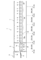
以下、図2及び図3を参照して、ガラスリボン15の温度及び粘度の制御の詳細を説明する。図3(a)は、製造装置1が設定する温度条件を概略的に示す図である。図3(b)は、図3(a)の温度条件に対応する粘度条件を概略的に示す図である。ガラスリボン15の粘度η(dPa・s)の常用対数logηを粘度η#と表記する。ガラスリボン15の雰囲気温度を雰囲気温度Taと表記する。ガラスリボン15がフロートバス3の下流端を出た時点の時刻を時刻t0とする。
Hereinafter, with reference to FIG.2 and FIG.3, the detail of control of the temperature and viscosity of the
図3(a)において縦軸は雰囲気温度Ta(℃)を示し、横軸は位置を示す。図3(b)において縦軸は粘度η#(dPa・s)を示し、横軸は位置を示す。図3(a)及び図3(b)の横軸において、位置に対応する時間をカッコ内に示した。 In FIG. 3A, the vertical axis indicates the ambient temperature Ta (° C.), and the horizontal axis indicates the position. In FIG. 3B, the vertical axis represents the viscosity η # (dPa · s), and the horizontal axis represents the position. On the horizontal axis in FIGS. 3A and 3B, the time corresponding to the position is shown in parentheses.
ヒータ群19は、フロートバス3の下流端(位置P0)でのガラスリボン15の粘度η#が粘度η0になるように、雰囲気温度Taを温度T0に設定する。ヒータ群21は、ゾーンZ01(時刻t0から時刻t1までの第0時間I01)において、粘度η#が粘度η0に保持されるように、雰囲気温度Taを温度T0に設定する。温度T0は粘度η0に対応する温度である。
The
ヒータ群23aは、ゾーンZ12において(時刻t1から時刻t2までの第1時間I12で)、粘度η#が粘度η0から粘度η2まで低下するように、雰囲気温度Taを温度T0から温度T2まで上昇させる。温度T2は粘度η2に対応する温度である。
In the zone Z12 (at the first time I12 from time t1 to time t2), the
ヒータ群23bは、ゾーンZ23において(時刻t2から時刻t3までの第2時間I23で)、粘度η#が粘度η2から粘度η3まで上昇するように、雰囲気温度Taを温度T2から温度T3まで下降させる。温度T3は粘度η3に対応する温度である。ヒータ群23bは、ゾーンZ34において(時刻t3から時刻t4までの第3時間I34で)、粘度η#が粘度η3から粘度η4まで上昇するように、雰囲気温度Taを温度T3から温度T4まで下降させる。温度T4は粘度η4に対応する温度である。ヒータ群23bは、ゾーンZ45において(時刻t4から時刻t5までの第4時間I45で)、粘度η#が粘度η4から粘度η5まで上昇するように、雰囲気温度Taを温度T4から温度T5まで下降させる。温度T5は粘度η5に対応する温度である。ヒータ群23bは、ゾーンZ45の終端から徐冷炉7の下流端において、所定の冷却速度に従って、雰囲気温度Taを温度T5から室温まで下降させ、ガラスリボン15を徐冷する。
In the zone Z23 (at the second time I23 from time t2 to time t3), the
以上、本実施形態1によれば、徐冷炉7の上流端(位置P1)からガラスリボン15を加熱するので(ゾーンZ12)、徐冷炉7による徐冷開始時の粘度η2に対応する温度よりも、リフトアウト部5(ゾーンZ01)におけるガラスリボン15の温度を低く保持できる。その結果、溶融錫9とローラ10との反応が抑制され、LOR傷の発生を抑制できる。また、徐冷炉7の上流端からガラスリボン15を加熱して、ガラスリボン15の粘度を低下させ、その後、ガラスリボン15を徐冷する。従って、LOR傷の発生を抑制するためにリフトアウト部5おけるガラスリボン15の温度を低く設定した場合でも、熱収縮を抑制可能な十分低い粘度η2に、ガラスリボン15の徐冷開始時の粘度を設定できる。その結果、ガラスリボン15から生成されるガラス基板17の熱収縮を抑制できる。以上の結果、ガラス基板17の熱収縮の抑制とLOR傷の発生の抑制との双方を実現できる。更に、附帯的にガラス基板17の反り及び変形の発生も抑制できる。
As mentioned above, according to this
(実施形態2)
[製造方法]
本発明の実施形態2におけるガラス基板製造方法(以下、「製造方法」と記載する。)は、実施形態1における製造装置1が実行するガラス基板製造方法である。以下、図1〜図4を参照して、製造方法を説明する。図4は、製造方法を示すフローチャートである。製造方法は、ガラスリボン15を徐冷炉7で徐冷してガラス基板17を製造する。工程S1にて、製造装置1は、フロートバス3に溶融ガラス13を供給する。工程S3にて、製造装置1は、フロートバス3で溶融ガラス13をガラスリボン15に成形する。
(Embodiment 2)
[Production method]
The glass substrate manufacturing method (hereinafter referred to as “manufacturing method”) in the second embodiment of the present invention is a glass substrate manufacturing method executed by the
工程S5にて、製造装置1は、ヒータ群21を制御して、フロートバス3と徐冷炉7との間のガラスリボン15の温度を、工程S7におけるガラスリボン15の温度よりも低い温度に保持する(ゾーンZ01、第0時間I01)。例えば、工程S5では、製造装置1は、ヒータ群21を制御して、ガラスリボン15の温度を、ガラスリボン15がフロートバス3から引き出された時点(時刻t0、位置P0)の温度に保持する。工程S7(加熱工程)にて、製造装置1は、ヒータ群23aを制御して、徐冷炉7内のゾーンZ12において、ガラスリボン15の粘度がフロートバス3から引き出された時点より低下するように、ガラスリボン15を加熱する(ゾーンZ12、第1時間I12)。
In step S5, the
工程S9にて、製造装置1は、工程S7によってガラスリボン15を加熱した後に、ヒータ群23bを制御して、ガラスリボン15を徐冷する(ゾーンZ23から徐冷炉7の下流端、第2時間I23から徐冷炉7の終端に至るまでの時間)。工程S11にて、製造装置1は、切断装置により、徐冷後のガラスリボン15を切断して、ガラス基板17を得る。つまり、ガラスリボン15からガラス基板17が切り出される。
In step S9, the
ここで、実際には、工程S1、工程S3、工程S5、工程S7、工程S9、及び工程S11は、同時に実行され、各工程の制御は、ガラス基板17の製造が完了するまで継続される。
Here, in practice, Step S1, Step S3, Step S5, Step S7, Step S9, and Step S11 are performed simultaneously, and control of each step is continued until the manufacture of the
以上、本実施形態2による製造方法によれば、徐冷炉7内のゾーンZ12においてガラスリボン15を加熱するので(工程S7)、実施形態1による製造装置1と同様の効果を奏する。
As mentioned above, according to the manufacturing method by this
次に、本発明が実施例に基づき具体的に説明されるが、本発明は以下の実施例によって限定されない。 Next, the present invention will be specifically described based on examples, but the present invention is not limited to the following examples.
図2、図3、及び図5を参照して、本発明の実施例1〜実施例3によるガラスリボン15の成形条件を比較例1〜比較例3と比較しながら説明する。図5は、本発明の実施例1〜3及び比較例1〜3による成形条件を示す図である。
With reference to FIGS. 2, 3, and 5, the molding conditions of the
実施例1〜実施例3の各々では、実施形態1の製造装置1は、実施形態2の製造方法によって、時刻t0〜時刻t5において、次の処理を実行する。ヒータ群21は、ガラスリボン15がフロートバス3を出てから徐冷炉7に入る前までの時刻t0〜時刻t1において(1.0分:第0時間I01)、ガラスリボン15の粘度η#が11.77±0.18(粘度η0)に保持されるように、ガラスリボン15の雰囲気温度Taを温度T0に設定し、ガラスリボン15の温度を制御する。粘度η0は、ガラスリボン15がフロートバスを出た時点のガラスリボン15の粘度η#である。
In each of Examples 1 to 3, the
ヒータ群23aは、ガラスリボン15が徐冷炉7に入ってから時刻t1〜時刻t2で(0.9分:第1時間I12)、ガラスリボン15の粘度η#が、11.71±0.14(粘度η2)になるように、かつ、粘度η0より小さくなるように、雰囲気温度Taを温度T0から温度T2に上昇させて、ガラスリボン15を加熱し、ガラスリボン15の粘度を制御する。その結果、ガラスリボン15から切り出されるガラス基板17の熱収縮を抑制可能な十分低い粘度に、ガラスリボン15の徐冷開始時(時刻t2)の粘度を設定できる。
The
ヒータ群23bは、粘度η#が粘度η2になった後の時刻t2〜時刻t3で(1.0分:第2時間I12)、粘度η#が12.70±0.35(粘度η3)になるように、雰囲気温度Taを温度T2から温度T3に上昇させ、ガラスリボン15の粘度を制御する。
The
ヒータ群23bは、粘度η#が粘度η3になった後の時刻t3〜時刻t4で(0.9分:第3時間I34)、粘度η#が13.88±0.68(粘度η4)になるように、雰囲気温度Taを温度T3から温度T4に上昇させ、ガラスリボン15の粘度を制御する。
The
ヒータ群23bは、粘度η#が粘度η4になった後の時刻t4〜時刻t5で(1.0分:第4時間I45)、粘度η#が14.60±0.65(粘度η5)になるように、雰囲気温度Taを温度T4から温度T5に上昇させ、ガラスリボン15の粘度を制御する。以降、徐冷炉7の終端まで、ガラスリボン15は徐冷され、その後、切断されてガラス基板17が得られる。
The
比較例1〜比較例3の各々では、時刻t0〜時刻t5において、次の処理が実行される。時刻t0〜時刻t1において、ガラスリボンの粘度η#が保持される。その後、時刻t1〜時刻t5において、ガラスリボンは徐冷される。以降、徐冷炉の終端まで、ガラスリボンは徐冷され、その後、切断されてガラス基板(以下、「ガラス基板C」と記載する。)が得られる。このように、比較例1〜比較例3では、実施例1〜実施例3の粘度を低下させる工程(図4の工程S7)を含まない。 In each of Comparative Examples 1 to 3, the following processing is executed at time t0 to time t5. From time t0 to time t1, the viscosity η # of the glass ribbon is maintained. Thereafter, the glass ribbon is gradually cooled from time t1 to time t5. Thereafter, the glass ribbon is gradually cooled to the end of the slow cooling furnace, and then cut to obtain a glass substrate (hereinafter referred to as “glass substrate C”). Thus, Comparative Example 1 to Comparative Example 3 do not include the step of reducing the viscosity of Example 1 to Example 3 (step S7 in FIG. 4).
なお、実施例1〜3及び比較例1〜3において、ガラスリボンの搬送速度Vcは、0.1m/sである。従って、実施例1〜3において、製造装置1のゾーンZ01〜ゾーンZ45(図2参照)の第0距離〜第4距離は、搬送速度Vcと時刻t0〜時刻t5とに基づいて算出される。
In Examples 1 to 3 and Comparative Examples 1 to 3, the conveyance speed Vc of the glass ribbon is 0.1 m / s. Therefore, in Examples 1 to 3, the 0th distance to the 4th distance of the zone Z01 to the zone Z45 (see FIG. 2) of the
次に、図6を参照して、実施例1〜3で得られたガラス基板17と比較例1〜3で得られたガラス基板Cとで、熱収縮率(ppm)、溝の蛇行幅(μm)、LOR傷の数(ガラス基板の1m2当たりの数)、及び反りを比較する。
Next, with reference to FIG. 6, with the
溝の蛇行幅は、化合物薄膜太陽電池の製造工程と同様にして、ガラス基板17及びガラス基板Cに金属(モリブデン)膜を形成し、レーザスクライビングにより1000mmの溝を形成したときの蛇行幅である。
The meandering width of the groove is the meandering width when a metal (molybdenum) film is formed on the
LOR傷とは、蛍光灯透過光で600luxの照度にて正常な視力の検査員が目視平面視検査して、1秒以内に視認できる程度の傷のうちリフトアウトローラ10(LOR)起因の傷を指す。正常な視力とは、裸眼視力又は矯正視力が0.8以上のことを指す。 LOR scratches are scratches caused by the lift-out roller 10 (LOR) among scratches that can be visually recognized within one second by an inspector with normal visual acuity at 600 lux illuminance with fluorescent lamp transmitted light. Point to. Normal visual acuity indicates that the naked eye visual acuity or the corrected visual acuity is 0.8 or more.
ガラス基板の反りは、次のようにして測定される。ガラス基板を1辺が1000mmの正方形状に形成する。つまり、ガラスリボンを切断して、1辺が1000mmの正方形状のガラス基板を製造する。そして、水平な定盤上にガラス基板の主面(以下、「主面P」と記載する。)が接する状態でガラス基板を載置する。さらに、定盤と主面Pとの隙間を測定する。測定された定盤と主面Pとの隙間がガラス基板の反りである。具体的には、主面Pの縁の各点と定盤との隙間を測定し、測定された複数の隙間のうちの最大値がガラス基板の反りである。つまり、ガラス基板の反りは、定盤と主面Pとの隙間の最大値である。 The warpage of the glass substrate is measured as follows. A glass substrate is formed in a square shape with one side of 1000 mm. That is, the glass ribbon is cut to produce a square glass substrate having a side of 1000 mm. And a glass substrate is mounted in the state which the main surface (henceforth "main surface P") of a glass substrate touches on a horizontal surface plate. Further, the gap between the surface plate and the main surface P is measured. The gap between the measured surface plate and the main surface P is the warp of the glass substrate. Specifically, a gap between each point on the edge of the main surface P and the surface plate is measured, and the maximum value among the plurality of measured gaps is the warp of the glass substrate. That is, the warp of the glass substrate is the maximum value of the gap between the surface plate and the main surface P.
図6は、実施例1〜3及び比較例1〜3により製造されたガラス基板17及びガラス基板Cの熱収縮率、溝の蛇行幅、LOR傷の数、並びにガラス基板17及びガラス基板Cの反りを示す図である。
FIG. 6 shows the thermal contraction rate, the meandering width of the groove, the number of LOR scratches of the
実施例1〜3では、ガラス基板17のLOR傷の数が4つ以下となった。なお、ガラス基板17のLOR傷が4つ以下ということは、ガラスリボン15のLOR傷が4つ以下ということと同義である。また、ガラス基板17の熱収縮率が310ppm以下であった。その結果、溝の蛇行幅の上限が4.8μm以下となった。溝の蛇行幅の上限が4.8μm以下の場合、溝の蛇行は化合物薄膜太陽電池の変換効率の向上を目的とした設計の許容範囲内に入る。従って、実施例1〜3によるガラス基板17は、化合物薄膜太陽電池用のガラス基板として好適である。例えば、化合物薄膜太陽電池は、カルコパイライト型薄膜太陽電池である。カルコパイライト型薄膜太陽電池は、例えば、CIS型薄膜太陽電池、又はCIGS型薄膜太陽電池である。CIS型薄膜太陽電池は、銅(Cu)、インジウム(In)、及びセレン(Se)を原料とする。CIGS型薄膜太陽電池は、銅(Cu)、インジウム(In)、ガリウム(Ga)、及びセレン(Se)を原料とする。以上の結果、LOR傷の発生が抑制されるとともに、熱収縮率が抑制されて変換効率の向上を妨げない化合物薄膜太陽電池用のガラス基板17を製造できる。
In Examples 1 to 3, the number of LOR scratches on the
更に附帯的にガラス基板17の反り及び変形の発生も抑制できる。実施例1〜3では、いずれもガラス基板17の反りが0.3mm未満であった。一般に、ガラス基板の反りが0.4mm以下であれば、太陽電池パネルを製造する際に、パネルのフレームとガラス基板との嵌合性において、問題がないとされている。実施例1〜3では、ガラス基板17の反りが0.4mm以下であり、太陽電池パネルの製造に好適である。
Furthermore, the occurrence of warpage and deformation of the
特に、実施例1及び実施例2では、LOR傷の数は3つ以下となった。なお、ガラス基板17のLOR傷が3つ以下ということは、ガラスリボン15のLOR傷が3つ以下ということと同義である。また、熱収縮率が270ppm以下であった。その結果、溝の蛇行幅の上限が4.5μm以下となった。従って、実施例1及び実施例2によるガラス基板17は、実施例3によるガラス基板17と比較して、LOR傷も少なく、また、化合物薄膜太陽電池用のガラス基板としてより一層好適である。
In particular, in Example 1 and Example 2, the number of LOR scratches was 3 or less. Note that three or less LOR scratches on the
一方、比較例1〜3では、LOR傷の数が4つを超えた。また、熱収縮率が310ppmを超えた。その結果、溝の蛇行幅の上限が4.8μmを超えた。溝の蛇行幅の上限が4.8μmを超える場合、溝の蛇行は化合物薄膜太陽電池の変換効率の向上を妨げるおそれがある。従って、比較例1〜3によるガラス基板Cは、化合物薄膜太陽電池用のガラス基板として不適である。 On the other hand, in Comparative Examples 1 to 3, the number of LOR scratches exceeded 4. Moreover, the thermal contraction rate exceeded 310 ppm. As a result, the upper limit of the meandering width of the groove exceeded 4.8 μm. When the upper limit of the meandering width of the groove exceeds 4.8 μm, the meandering of the groove may hinder the improvement of the conversion efficiency of the compound thin film solar cell. Therefore, the glass substrate C by Comparative Examples 1-3 is unsuitable as a glass substrate for compound thin film solar cells.
更に、比較例1〜3ではガラス基板Cの反りが0.5mm以上となった。反りが0.4mmより大きい場合、太陽電池パネルを製造する際に、パネルのフレームとガラス基板との嵌合性において、問題が生じるおそれがある。 Furthermore, in Comparative Examples 1 to 3, the warpage of the glass substrate C was 0.5 mm or more. If the warpage is larger than 0.4 mm, there may be a problem in the fit between the panel frame and the glass substrate when manufacturing the solar cell panel.
次に、熱収縮率を測定するための熱処理条件を説明する。ガラス基板17及びガラス基板Cに対して、室温から所定昇温速度で加熱して所定温度Th(以下、「熱処理温度Th」と記載する。)で所定時間th(以下、「熱処理時間th」と記載する。)にわたって熱処理し、所定降温速度で室温に戻された。所定昇温速度は10℃/分である。熱処理時間thは60分である。所定降温速度は5℃/分である。熱処理温度Thは、ガラス基板の歪点から35℃を差し引いた温度である。実施例1〜3及び比較例1〜3では、ガラス基板17及びガラス基板Cの歪点は615℃である。従って、熱処理温度Thは580℃である。
Next, heat treatment conditions for measuring the heat shrinkage rate will be described. The
次に、図7を参照して、熱収縮率と熱処理時間thとの関係を説明する。図7は、実施例1〜3及び比較例1〜3により製造されたガラス基板17及びガラス基板Cの熱収縮率と熱処理時間thとの関係を示す図である。図7の熱収縮率曲線A1〜A3及び熱収縮率曲線B1〜B3は、図6の熱収縮率(熱処理時間thが60分)に基づいてシミュレーションした結果である。熱収縮率曲線A1〜A3は、それぞれ、実施例1〜3に対応する。熱収縮率曲線B1〜B3は、それぞれ、比較例1〜3に対応する。実施例1〜3によるガラス基板17は、広い熱処理時間thにわたって、比較例1〜3によるガラス基板Cよりも、熱収縮率は小さい。
Next, the relationship between the thermal shrinkage rate and the heat treatment time th will be described with reference to FIG. FIG. 7 is a diagram showing the relationship between the heat shrinkage rate and the heat treatment time th of the
一般的には、レーザスクライビング時のレーザ光の照射によってガラス基板の局所の温度が熱収縮を起こしうる温度以上まで上昇している時間(熱処理時間thに相当)は3分以下である。従って、熱収縮率曲線から予測できるように、熱処理時間thが3分以下の場合であっても、実施例1〜3のガラス基板17の熱収縮率は、比較例1〜3のガラス基板Cの熱収縮率よりも小さい。従って、実施例1〜3によるガラス基板17は、比較例1〜3によるガラス基板Cよりも、変換効率の向上を妨げず、化合物薄膜太陽電池用のガラス基板として好適である。
In general, the time (corresponding to the heat treatment time th) during which the local temperature of the glass substrate is raised to a temperature at which heat shrinkage or more can be caused by laser light irradiation during laser scribing is 3 minutes or less. Therefore, as can be predicted from the heat shrinkage rate curve, even when the heat treatment time th is 3 minutes or less, the heat shrinkage rate of the
次に、実施例1〜3のガラス基板17の組成を説明する。ガラス基板17は、アルカリ金属を含有する高歪点アルミノシリケートガラスである。具体的には、ガラス基板17は、ガラス組成として、質量%で、SiO2を51%、Al2O3を13%、B2O3を0%、MgOを0%、CaOを6%、SrOを12%、BaOを3%、Na2Oを6%、K2Oを4%、ZrO2を5%含有し、かつ歪点が615℃である。なお、比較例1〜3のガラス基板Cの組成及び歪点は、ガラス基板17と同じである。
Next, the composition of the
このように、ガラス基板17には6%のNa2O(アルカリ金属)が含まれている。6%の質量%は、化合物薄膜太陽電池の発電効率を高めるNaの拡散が十分に行える量である。また、歪点が615℃であり、610℃を超えている。歪点が610℃を超えたガラス基板17は、化合物薄膜太陽電池を製造する際のセレン化/硫化工程でも、軟化及び変形し難い。以上の結果、実施例1〜3におけるガラス基板17は、化合物薄膜太陽電池用のガラス基板として好適である。また、アルカリ金属を含有するガラスにはLOR傷が付き易いが、実施例1〜3では、ガラスリボン15がフロートバス3を出てから徐冷炉7に入る前までの時刻t0〜時刻t1において、ガラスリボン15の温度を低く保持して、LOR傷の発生を抑制している。従って、実施形態1の製造装置1及び実施形態2の製造方法は、アルカリ金属を含有するガラス基板17の製造に好適である。
Thus, the
ここで、Na2O等の成分は、図1のフロートバス3に供給される溶融ガラス13に含まれる。即ち、図4の工程S1では、Na2O等の成分を含有する溶融ガラス13がフロートバス3に供給される。その結果、ガラスリボン15、ひいては、ガラス基板17にも、Na2O等の成分が含まれる。
Here, components such as Na 2 O are included in the
なお、本発明は、上記の実施形態に限られるものではなく、その要旨を逸脱しない範囲で種々の態様において実施することが可能であり、例えば、以下のような変形も可能である。 The present invention is not limited to the above-described embodiment, and can be implemented in various modes without departing from the gist thereof. For example, the following modifications are possible.
(1)ガラス基板17の組成及び歪点は、実施例1〜3で製造されたガラス基板17の組成及び歪点に限定されない。例えば、ガラス基板17は、ガラス組成として、質量%で、SiO2を45〜60%、Al2O3を8.0超〜18%、B2O3を0〜15%(但し、15%を含まず)、MgO+CaO+SrO+BaOを1〜40%、Na2O+K2Oを1〜30%含有し、かつ歪点が580℃超であることができる。ZrO2は任意成分であり、質量%で、2〜6%を含むことができる。
(1) The composition and strain point of the
(2)図6に関連して説明した熱処理温度Thは、ガラス基板17の歪点から35℃を差し引いた温度であった。ただし、熱処理温度Thは、ガラス基板17の歪点から35℃を差し引いた温度に対して±15℃の範囲内の温度でもよい。
(2) The heat treatment temperature Th described in relation to FIG. 6 was a temperature obtained by subtracting 35 ° C. from the strain point of the
本発明は、熱収縮、LOR傷、及びガラス基板の反りが最終生産物の品質に影響を及ぼすガラス基板を製造、使用する分野に利用可能である。例えば、化合物薄膜太陽電池用ガラス基板を製造、使用する分野に利用可能である。 The present invention can be used in the field of manufacturing and using glass substrates where heat shrinkage, LOR scratches, and warping of the glass substrate affect the quality of the final product. For example, it can be used in the field of manufacturing and using a glass substrate for a compound thin film solar cell.
1 ガラス基板製造装置
3 フロートバス
5 リフトアウト部
7 徐冷炉(レア)
9 溶融錫
10 リフトアウトローラ
11 搬送ローラ
13 溶融ガラス
15 ガラスリボン
17 ガラス基板
19 ヒータ群
21 ヒータ群
23(23a,23b) ヒータ群
24 搬送方向
50 CIGS型薄膜太陽電池
51 ガラス基板
53 金属裏面電極層
55 光吸収層
57 バッファ層
59 透明導電膜層
61 溝間領域
Z01 ゾーン
Z12 ゾーン
Z23 ゾーン
Z34 ゾーン
Z45 ゾーン
P0 位置
P1 位置
P2 位置
P3 位置
P4 位置
P5 位置
p1 溝
p2 溝
p3 溝
1 Glass
DESCRIPTION OF
Claims (7)
フロートバスで溶融ガラスを前記ガラスリボンに成形する工程と、
前記徐冷炉内の上流ゾーンにおいて、前記ガラスリボンの雰囲気温度を制御することにより、前記ガラスリボンの粘度が前記フロートバスから引き出された時点より低下するように、前記ガラスリボンを加熱する加熱工程と、
前記加熱工程によって前記ガラスリボンを加熱した後、前記徐冷炉において、前記ガラスリボンを徐冷する工程と
を含むことを特徴とする、ガラス基板製造方法。 A method of producing a glass substrate by slowly cooling a glass ribbon in a slow cooling furnace,
Forming molten glass into the glass ribbon with a float bath;
In the upstream zone in the slow cooling furnace, by controlling the atmospheric temperature of the glass ribbon, a heating step of heating the glass ribbon so that the viscosity of the glass ribbon is lower than when it is drawn from the float bath,
And a step of slowly cooling the glass ribbon in the slow cooling furnace after heating the glass ribbon by the heating step.
前記加熱工程で前記ガラスリボンの粘度(dPa・s)の常用対数が11.71±0.14になった後、第2時間で粘度(dPa・s)の常用対数が12.70±0.35になるように前記ガラスリボンの粘度を制御する工程と、
粘度(dPa・s)の常用対数が12.70±0.35になった後、第3時間で粘度(dPa・s)の常用対数が13.88±0.68になるように前記ガラスリボンの粘度を制御する工程と、
粘度(dPa・s)の常用対数が13.88±0.68になった後、第4時間で粘度(dPa・s)の常用対数が14.60±0.65になるように前記ガラスリボンの粘度を制御する工程と
をさらに含むことを特徴とする、請求項4に記載のガラス基板製造方法。 The glass ribbon so that the common logarithm of the viscosity (dPa · s) of the glass ribbon is maintained at 11.77 ± 0.18 for the time from when the glass ribbon leaves the float bath to before entering the slow cooling furnace. Controlling the temperature of
After the heating step, the common logarithm of the viscosity (dPa · s) of the glass ribbon is 11.71 ± 0.14, and the common logarithm of the viscosity (dPa · s) is 12.70 ± 0. A step of controlling the viscosity of the glass ribbon so as to be 35;
The glass ribbon so that the common logarithm of viscosity (dPa · s) becomes 13.88 ± 0.68 in the third time after the common logarithm of viscosity (dPa · s) becomes 12.70 ± 0.35. A step of controlling the viscosity of
The glass ribbon so that the common logarithm of viscosity (dPa · s) becomes 14.60 ± 0.65 in the fourth time after the common logarithm of viscosity (dPa · s) becomes 13.88 ± 0.68. The method for producing a glass substrate according to claim 4, further comprising a step of controlling the viscosity of the glass substrate.
前記溶融ガラスを前記フロートバスに供給する工程をさらに含むことを特徴とする、請求項1から請求項5のいずれかに記載のガラス基板製造方法。 The molten glass contains an alkali metal,
The method for producing a glass substrate according to any one of claims 1 to 5, further comprising a step of supplying the molten glass to the float bath.
溶融ガラスを前記ガラスリボンに成形するフロートバスと、
前記フロートバスよりも下流側に配置され、前記ガラスリボンを徐冷する徐冷炉と
を備え、
前記徐冷炉は、前記徐冷炉内の上流ゾーンにおいて、前記ガラスリボンの雰囲気温度を制御することにより、前記ガラスリボンの粘度が前記フロートバスから引き出された時点より低下するように、前記ガラスリボンを加熱し、加熱後に前記ガラスリボンを徐冷することを特徴とする、ガラス基板製造装置。 An apparatus for producing a glass substrate from a glass ribbon,
A float bath for forming molten glass into the glass ribbon;
A slow cooling furnace that is disposed downstream of the float bath and slowly cools the glass ribbon,
The slow cooling furnace heats the glass ribbon in the upstream zone in the slow cooling furnace by controlling the atmospheric temperature of the glass ribbon so that the viscosity of the glass ribbon is lower than when it is drawn out of the float bath. An apparatus for producing a glass substrate, wherein the glass ribbon is gradually cooled after heating.
Priority Applications (1)
| Application Number | Priority Date | Filing Date | Title |
|---|---|---|---|
| JP2013234773A JP6225652B2 (en) | 2013-03-26 | 2013-11-13 | Glass substrate manufacturing method and glass substrate manufacturing apparatus |
Applications Claiming Priority (3)
| Application Number | Priority Date | Filing Date | Title |
|---|---|---|---|
| JP2013063276 | 2013-03-26 | ||
| JP2013063276 | 2013-03-26 | ||
| JP2013234773A JP6225652B2 (en) | 2013-03-26 | 2013-11-13 | Glass substrate manufacturing method and glass substrate manufacturing apparatus |
Publications (2)
| Publication Number | Publication Date |
|---|---|
| JP2014208565A JP2014208565A (en) | 2014-11-06 |
| JP6225652B2 true JP6225652B2 (en) | 2017-11-08 |
Family
ID=51903106
Family Applications (1)
| Application Number | Title | Priority Date | Filing Date |
|---|---|---|---|
| JP2013234773A Expired - Fee Related JP6225652B2 (en) | 2013-03-26 | 2013-11-13 | Glass substrate manufacturing method and glass substrate manufacturing apparatus |
Country Status (1)
| Country | Link |
|---|---|
| JP (1) | JP6225652B2 (en) |
Families Citing this family (3)
| Publication number | Priority date | Publication date | Assignee | Title |
|---|---|---|---|---|
| JP6041004B2 (en) * | 2015-02-09 | 2016-12-07 | 旭硝子株式会社 | Glass substrate |
| EP3585741B1 (en) * | 2017-03-24 | 2024-02-28 | Corning Incorporated | Systems and methods for measuring the temperature of glass during tube conversion |
| CN111943503A (en) * | 2020-08-24 | 2020-11-17 | 中国洛阳浮法玻璃集团有限责任公司 | Preparation method of high-hardness ultrathin float glass |
Family Cites Families (5)
| Publication number | Priority date | Publication date | Assignee | Title |
|---|---|---|---|---|
| JP2005320180A (en) * | 2004-05-06 | 2005-11-17 | Central Glass Co Ltd | Thermal treatment method for reducing heat-shrink rate of glass plate |
| JP5309858B2 (en) * | 2007-10-12 | 2013-10-09 | セントラル硝子株式会社 | Method for producing thin glass plate by float method |
| FR2934588B1 (en) * | 2008-07-30 | 2011-07-22 | Fives Stein | METHOD AND DEVICE FOR MAKING A STRUCTURE ON ONE OF THE FACES OF A GLASS RIBBON |
| JP5223594B2 (en) * | 2008-10-29 | 2013-06-26 | 旭硝子株式会社 | Manufacturing method of flat display panel |
| JP5896338B2 (en) * | 2011-01-18 | 2016-03-30 | 日本電気硝子株式会社 | Method for producing tempered glass and method for producing tempered glass plate |
-
2013
- 2013-11-13 JP JP2013234773A patent/JP6225652B2/en not_active Expired - Fee Related
Also Published As
| Publication number | Publication date |
|---|---|
| JP2014208565A (en) | 2014-11-06 |
Similar Documents
| Publication | Publication Date | Title |
|---|---|---|
| JP5831212B2 (en) | Manufacturing method of glass strip | |
| US9199874B2 (en) | Method for depositing a thin film, and resulting material | |
| JP6050261B2 (en) | Photocell including semiconductor device and photovoltaic module including the photocell | |
| JP5752787B2 (en) | Glass substrate manufacturing method and molding apparatus | |
| CN106458681B (en) | Method and apparatus for producing thin glass ribbon and thin glass ribbon produced according to such method | |
| JP2013530915A (en) | Glass substrate for high temperature | |
| JP2009173524A (en) | Process and apparatus for producing glass plate | |
| KR20150111863A (en) | Float process for producing a float glass pane and float glass pane | |
| JP6225652B2 (en) | Glass substrate manufacturing method and glass substrate manufacturing apparatus | |
| JP6144740B2 (en) | Manufacturing method of glass substrate for display | |
| US20120144867A1 (en) | System and method for producing patterned heat-strengthened glass | |
| TW201228951A (en) | Method for manufacturing molded glass plate, and device for manufacturing molded glass plate | |
| JP6999899B2 (en) | Method for manufacturing a glass roll with a transparent conductive film and a glass sheet with a transparent conductive film | |
| US20130313671A1 (en) | Substrate for a photovoltaic cell | |
| JPWO2014112415A1 (en) | Manufacturing method of glass substrate with laminated film | |
| JP2013063880A (en) | Glass plate | |
| RU2444478C1 (en) | Method of bending sheet glass | |
| WO2013008895A1 (en) | Method for manufacturing layered-film-bearing glass substrate | |
| JP6379678B2 (en) | Manufacturing method of glass substrate | |
| JP6041004B2 (en) | Glass substrate | |
| JP6082434B2 (en) | Glass substrate manufacturing method and glass substrate | |
| TW201600474A (en) | Glass substrate manufacturing method and glass substrate | |
| JP2016222513A (en) | Glass substrate for solar battery | |
| WO2009081741A1 (en) | Process and apparatus for producing glass plate | |
| JP2016088769A (en) | Method for heat-treating glass substrate and method for manufacturing glass substrate |
Legal Events
| Date | Code | Title | Description |
|---|---|---|---|
| A621 | Written request for application examination |
Free format text: JAPANESE INTERMEDIATE CODE: A621 Effective date: 20160721 |
|
| A977 | Report on retrieval |
Free format text: JAPANESE INTERMEDIATE CODE: A971007 Effective date: 20170224 |
|
| A131 | Notification of reasons for refusal |
Free format text: JAPANESE INTERMEDIATE CODE: A131 Effective date: 20170307 |
|
| A521 | Written amendment |
Free format text: JAPANESE INTERMEDIATE CODE: A523 Effective date: 20170427 |
|
| TRDD | Decision of grant or rejection written | ||
| A01 | Written decision to grant a patent or to grant a registration (utility model) |
Free format text: JAPANESE INTERMEDIATE CODE: A01 Effective date: 20170912 |
|
| A61 | First payment of annual fees (during grant procedure) |
Free format text: JAPANESE INTERMEDIATE CODE: A61 Effective date: 20170925 |
|
| R150 | Certificate of patent or registration of utility model |
Ref document number: 6225652 Country of ref document: JP Free format text: JAPANESE INTERMEDIATE CODE: R150 |
|
| LAPS | Cancellation because of no payment of annual fees |