JP6224252B2 - Target processing unit - Google Patents
Target processing unit Download PDFInfo
- Publication number
- JP6224252B2 JP6224252B2 JP2016539575A JP2016539575A JP6224252B2 JP 6224252 B2 JP6224252 B2 JP 6224252B2 JP 2016539575 A JP2016539575 A JP 2016539575A JP 2016539575 A JP2016539575 A JP 2016539575A JP 6224252 B2 JP6224252 B2 JP 6224252B2
- Authority
- JP
- Japan
- Prior art keywords
- conduit
- processing unit
- projection lens
- lens assembly
- guide
- Prior art date
- Legal status (The legal status is an assumption and is not a legal conclusion. Google has not performed a legal analysis and makes no representation as to the accuracy of the status listed.)
- Active
Links
Images


Classifications
-
- H—ELECTRICITY
- H01—ELECTRIC ELEMENTS
- H01J—ELECTRIC DISCHARGE TUBES OR DISCHARGE LAMPS
- H01J37/00—Discharge tubes with provision for introducing objects or material to be exposed to the discharge, e.g. for the purpose of examination or processing thereof
- H01J37/02—Details
- H01J37/023—Means for mechanically adjusting components not otherwise provided for
-
- G—PHYSICS
- G03—PHOTOGRAPHY; CINEMATOGRAPHY; ANALOGOUS TECHNIQUES USING WAVES OTHER THAN OPTICAL WAVES; ELECTROGRAPHY; HOLOGRAPHY
- G03F—PHOTOMECHANICAL PRODUCTION OF TEXTURED OR PATTERNED SURFACES, e.g. FOR PRINTING, FOR PROCESSING OF SEMICONDUCTOR DEVICES; MATERIALS THEREFOR; ORIGINALS THEREFOR; APPARATUS SPECIALLY ADAPTED THEREFOR
- G03F7/00—Photomechanical, e.g. photolithographic, production of textured or patterned surfaces, e.g. printing surfaces; Materials therefor, e.g. comprising photoresists; Apparatus specially adapted therefor
- G03F7/70—Microphotolithographic exposure; Apparatus therefor
- G03F7/708—Construction of apparatus, e.g. environment aspects, hygiene aspects or materials
-
- B—PERFORMING OPERATIONS; TRANSPORTING
- B01—PHYSICAL OR CHEMICAL PROCESSES OR APPARATUS IN GENERAL
- B01J—CHEMICAL OR PHYSICAL PROCESSES, e.g. CATALYSIS OR COLLOID CHEMISTRY; THEIR RELEVANT APPARATUS
- B01J19/00—Chemical, physical or physico-chemical processes in general; Their relevant apparatus
- B01J19/08—Processes employing the direct application of electric or wave energy, or particle radiation; Apparatus therefor
- B01J19/12—Processes employing the direct application of electric or wave energy, or particle radiation; Apparatus therefor employing electromagnetic waves
-
- G—PHYSICS
- G03—PHOTOGRAPHY; CINEMATOGRAPHY; ANALOGOUS TECHNIQUES USING WAVES OTHER THAN OPTICAL WAVES; ELECTROGRAPHY; HOLOGRAPHY
- G03F—PHOTOMECHANICAL PRODUCTION OF TEXTURED OR PATTERNED SURFACES, e.g. FOR PRINTING, FOR PROCESSING OF SEMICONDUCTOR DEVICES; MATERIALS THEREFOR; ORIGINALS THEREFOR; APPARATUS SPECIALLY ADAPTED THEREFOR
- G03F7/00—Photomechanical, e.g. photolithographic, production of textured or patterned surfaces, e.g. printing surfaces; Materials therefor, e.g. comprising photoresists; Apparatus specially adapted therefor
- G03F7/70—Microphotolithographic exposure; Apparatus therefor
- G03F7/708—Construction of apparatus, e.g. environment aspects, hygiene aspects or materials
- G03F7/70808—Construction details, e.g. housing, load-lock, seals or windows for passing light in or out of apparatus
- G03F7/70825—Mounting of individual elements, e.g. mounts, holders or supports
-
- G—PHYSICS
- G03—PHOTOGRAPHY; CINEMATOGRAPHY; ANALOGOUS TECHNIQUES USING WAVES OTHER THAN OPTICAL WAVES; ELECTROGRAPHY; HOLOGRAPHY
- G03F—PHOTOMECHANICAL PRODUCTION OF TEXTURED OR PATTERNED SURFACES, e.g. FOR PRINTING, FOR PROCESSING OF SEMICONDUCTOR DEVICES; MATERIALS THEREFOR; ORIGINALS THEREFOR; APPARATUS SPECIALLY ADAPTED THEREFOR
- G03F7/00—Photomechanical, e.g. photolithographic, production of textured or patterned surfaces, e.g. printing surfaces; Materials therefor, e.g. comprising photoresists; Apparatus specially adapted therefor
- G03F7/70—Microphotolithographic exposure; Apparatus therefor
- G03F7/708—Construction of apparatus, e.g. environment aspects, hygiene aspects or materials
- G03F7/70808—Construction details, e.g. housing, load-lock, seals or windows for passing light in or out of apparatus
- G03F7/70833—Mounting of optical systems, e.g. mounting of illumination system, projection system or stage systems on base-plate or ground
-
- G—PHYSICS
- G03—PHOTOGRAPHY; CINEMATOGRAPHY; ANALOGOUS TECHNIQUES USING WAVES OTHER THAN OPTICAL WAVES; ELECTROGRAPHY; HOLOGRAPHY
- G03F—PHOTOMECHANICAL PRODUCTION OF TEXTURED OR PATTERNED SURFACES, e.g. FOR PRINTING, FOR PROCESSING OF SEMICONDUCTOR DEVICES; MATERIALS THEREFOR; ORIGINALS THEREFOR; APPARATUS SPECIALLY ADAPTED THEREFOR
- G03F7/00—Photomechanical, e.g. photolithographic, production of textured or patterned surfaces, e.g. printing surfaces; Materials therefor, e.g. comprising photoresists; Apparatus specially adapted therefor
- G03F7/70—Microphotolithographic exposure; Apparatus therefor
- G03F7/708—Construction of apparatus, e.g. environment aspects, hygiene aspects or materials
- G03F7/70858—Environment aspects, e.g. pressure of beam-path gas, temperature
- G03F7/70883—Environment aspects, e.g. pressure of beam-path gas, temperature of optical system
- G03F7/70891—Temperature
-
- G—PHYSICS
- G03—PHOTOGRAPHY; CINEMATOGRAPHY; ANALOGOUS TECHNIQUES USING WAVES OTHER THAN OPTICAL WAVES; ELECTROGRAPHY; HOLOGRAPHY
- G03F—PHOTOMECHANICAL PRODUCTION OF TEXTURED OR PATTERNED SURFACES, e.g. FOR PRINTING, FOR PROCESSING OF SEMICONDUCTOR DEVICES; MATERIALS THEREFOR; ORIGINALS THEREFOR; APPARATUS SPECIALLY ADAPTED THEREFOR
- G03F7/00—Photomechanical, e.g. photolithographic, production of textured or patterned surfaces, e.g. printing surfaces; Materials therefor, e.g. comprising photoresists; Apparatus specially adapted therefor
- G03F7/70—Microphotolithographic exposure; Apparatus therefor
- G03F7/708—Construction of apparatus, e.g. environment aspects, hygiene aspects or materials
- G03F7/70858—Environment aspects, e.g. pressure of beam-path gas, temperature
- G03F7/709—Vibration, e.g. vibration detection, compensation, suppression or isolation
-
- G—PHYSICS
- G03—PHOTOGRAPHY; CINEMATOGRAPHY; ANALOGOUS TECHNIQUES USING WAVES OTHER THAN OPTICAL WAVES; ELECTROGRAPHY; HOLOGRAPHY
- G03F—PHOTOMECHANICAL PRODUCTION OF TEXTURED OR PATTERNED SURFACES, e.g. FOR PRINTING, FOR PROCESSING OF SEMICONDUCTOR DEVICES; MATERIALS THEREFOR; ORIGINALS THEREFOR; APPARATUS SPECIALLY ADAPTED THEREFOR
- G03F7/00—Photomechanical, e.g. photolithographic, production of textured or patterned surfaces, e.g. printing surfaces; Materials therefor, e.g. comprising photoresists; Apparatus specially adapted therefor
- G03F7/70—Microphotolithographic exposure; Apparatus therefor
- G03F7/708—Construction of apparatus, e.g. environment aspects, hygiene aspects or materials
- G03F7/70975—Assembly, maintenance, transport or storage of apparatus
-
- H—ELECTRICITY
- H01—ELECTRIC ELEMENTS
- H01J—ELECTRIC DISCHARGE TUBES OR DISCHARGE LAMPS
- H01J37/00—Discharge tubes with provision for introducing objects or material to be exposed to the discharge, e.g. for the purpose of examination or processing thereof
- H01J37/02—Details
- H01J37/04—Arrangements of electrodes and associated parts for generating or controlling the discharge, e.g. electron-optical arrangement, ion-optical arrangement
- H01J37/10—Lenses
-
- H—ELECTRICITY
- H01—ELECTRIC ELEMENTS
- H01J—ELECTRIC DISCHARGE TUBES OR DISCHARGE LAMPS
- H01J37/00—Discharge tubes with provision for introducing objects or material to be exposed to the discharge, e.g. for the purpose of examination or processing thereof
- H01J37/02—Details
- H01J37/20—Means for supporting or positioning the objects or the material; Means for adjusting diaphragms or lenses associated with the support
-
- H—ELECTRICITY
- H01—ELECTRIC ELEMENTS
- H01J—ELECTRIC DISCHARGE TUBES OR DISCHARGE LAMPS
- H01J37/00—Discharge tubes with provision for introducing objects or material to be exposed to the discharge, e.g. for the purpose of examination or processing thereof
- H01J37/30—Electron-beam or ion-beam tubes for localised treatment of objects
- H01J37/3002—Details
- H01J37/3007—Electron or ion-optical systems
-
- H—ELECTRICITY
- H01—ELECTRIC ELEMENTS
- H01J—ELECTRIC DISCHARGE TUBES OR DISCHARGE LAMPS
- H01J37/00—Discharge tubes with provision for introducing objects or material to be exposed to the discharge, e.g. for the purpose of examination or processing thereof
- H01J37/30—Electron-beam or ion-beam tubes for localised treatment of objects
- H01J37/317—Electron-beam or ion-beam tubes for localised treatment of objects for changing properties of the objects or for applying thin layers thereon, e.g. for ion implantation
- H01J37/3174—Particle-beam lithography, e.g. electron beam lithography
- H01J37/3177—Multi-beam, e.g. fly's eye, comb probe
Description
本発明は、一般的には標的処理ユニットに関する。さらに、本発明は、標的処理ユニットで使用するための投影レンズアセンブリに関する。別の態様は、中間導管アセンブリと、標的処理ユニットの真空チャンバと、中間導管アセンブリを備える標的処理ユニットとに関する。 The present invention relates generally to target processing units. The invention further relates to a projection lens assembly for use in a target processing unit. Another aspect relates to an intermediate conduit assembly, a vacuum chamber of a target processing unit, and a target processing unit that includes the intermediate conduit assembly.
電子機器の分野では、電子デバイス構成要素を機能的に一体化されたモジュールごとにグループ化することが、欠陥を有する構成要素の交換に必要とされる時間を短縮させる助けとなり得ると共に、これがかかるモジュール式デバイスの修理のためのダウンタイムをより短縮させることが知られている。モジュール式構成要素設計は、メンテナンス時間が短縮される結果として生産率の向上が実現され得るため、生産ラインで使用される電子デバイスについては特に望ましい。 In the electronics field, grouping electronic device components into functionally integrated modules can help reduce and reduce the time required to replace defective components. It is known to further reduce downtime for repair of modular devices. Modular component design is particularly desirable for electronic devices used in production lines, as increased production rates can be realized as a result of reduced maintenance time.
荷電粒子ビーム処理デバイス等では、モジュール原理の実装は簡単ではない。この主な理由は、様々な粒子ビーム発生および操作ステージ(例えば、ビーム源、コリメータ、ビームスプリッタ、ビームブランカ、ビームストッパ、ビーム偏向器、およびレンズ素子など)が協働して、これらの各ステージを越えるビームを形成および制御するからである。コンピュータ設計者は、モジュール間のデータ/信号交換と、出力要件と、電磁適合性、および温度管理に関する課題を主に取り扱う。ビーム処理デバイスにモジュール原理を適用することは、上記のことに加えて、ビームアライメントの問題と、場較正と、モジュール間の機械的結合(切離し)とをさらに考慮する必要があるため、大幅により複雑である。さらに、全ての構成要素が、同一の粒子ビームを操作するために共に動作するため、高いビームアライメント精度(モジュールへの分割がより少ない)と高いメンテナンス効率(より多数のモジュール)との間の最適なバランスを実現するように、モジュールを形成すべき好ましい構成要素群を特定することは簡単ではない。 In a charged particle beam processing device or the like, it is not easy to implement the module principle. The main reason for this is that various particle beam generation and manipulation stages (eg, beam source, collimator, beam splitter, beam blanker, beam stopper, beam deflector, lens element, etc.) work together in each of these stages. This is because the beam exceeding 1 is formed and controlled. Computer designers primarily address issues related to data / signal exchange between modules, power requirements, electromagnetic compatibility, and thermal management. Applying the module principle to the beam processing device, in addition to the above, greatly increases the need for further consideration of beam alignment issues, field calibration, and mechanical coupling (disconnection) between modules. It is complicated. In addition, all components work together to operate the same particle beam, so an optimum between high beam alignment accuracy (less division into modules) and high maintenance efficiency (more modules) In order to achieve a good balance, it is not easy to specify a preferred group of components that should form a module.
国際特許出願WO2013/037486は、鉛直方向に積層されたモジュールから熱的に安定化された整列された投影コラムを形成するための、ビーム露光システムのキャリアフレーム内での様々な投影モジュールの位置決めと平面整列とを論じている。 International patent application WO2013 / 037486 describes the positioning of various projection modules within the carrier frame of a beam exposure system to form a thermally stabilized aligned projection column from vertically stacked modules. Discusses planar alignment.
しかし、WO2013/037486は、投影モジュールのための詳細な構成を開示しておらず、かかる投影モジュール(例えば投影レンズ構成体など)に信号と流体とを供給しかかる投影モジュールから信号と流体とを放出する様々な導管の接続についての解決策を示していない。US2011/193573A1は、1本以上の露光ビームをターゲット上に集束させるための投影レンズシステムと、ターゲットを支える可動テーブルと、投影レンズシステムの最後の集束要素とターゲットの表面との間の距離に関連する測定を行なう静電容量感知システムと、静電容量感知システムからの信号に少なくとも部分的に基づいて、ターゲットの位置を調整するために、可動テーブルの動きを制御する制御ユニットと、を具備する、リソグラフィマシンのための統合されたセンサシステムを開示している。静電容量感知システムは、複数の静電容量センサを具備しており、各静電容量センサは、薄膜構造を備えている。静電容量センサと投影レンズシステムの最後の集束要素は、共通のベースに直接にマウントされ、静電容量センサは、投影レンズシステムの最後の集束要素の縁部のすぐ近くに配置される。 However, WO2013 / 037486 does not disclose a detailed configuration for the projection module, and supplies signals and fluids to such projection modules (eg, projection lens arrangements, etc.) and signals and fluids from such projection modules. It does not provide a solution for connecting the various conduits that emit. US 2011/193573 A1 relates to the distance between a projection lens system for focusing one or more exposure beams on a target, a movable table supporting the target, and the last focusing element of the projection lens system and the surface of the target. A capacitive sensing system that performs the measurements to be performed, and a control unit that controls movement of the movable table to adjust the position of the target based at least in part on a signal from the capacitive sensing system. Discloses an integrated sensor system for a lithography machine. The capacitance sensing system includes a plurality of capacitance sensors, and each capacitance sensor has a thin film structure. The capacitive sensor and the last focusing element of the projection lens system are mounted directly on a common base, and the capacitive sensor is located in the immediate vicinity of the edge of the last focusing element of the projection lens system.
投影コラムの効率的なモジュール式構造化とメンテナンスとを可能にすると共に、様々な導管の接続を最適化する、投影レンズ構成と標的を処理するためのリソグラフィユニットまたは検査ユニットとを提供することが望ましい。 Providing a projection lens configuration and a lithographic or inspection unit for processing a target that enables efficient modular structuring and maintenance of the projection column and optimizes the connection of various conduits desirable.
したがって、第1の態様によれば、標的に向かって投影ビームを配向するための投影レンズアセンブリが提供される。この投影レンズアセンブリは、レンズ素子を収容するための平面レンズ支持体と、ここにおいて、レンズ支持体は、面に広がり、接続領域と側方エッジとを備え、レンズ支持体は、標的処理ユニットのキャリアフレーム内へと前述の面に対して平行な挿入方向に沿った挿入用に構成される;接続領域から起始し、前述の面に対して平行に配向された複数の導管と;導管を収容するように構成された導管ガイド体とを備え、導管ガイド体は、側方エッジを越えて側方領域まで、前述の面に対して平行におよび挿入方向に対して垂直な非ゼロの方向成分を有して接続領域から導管を案内するように構成された第1のガイド部分を備え、ガイド体は、導管ガイド体の傾斜エッジに向かって、前述の面に対して垂直な非ゼロの方向成分を有して側方領域から導管を案内するための第2のガイド部分を備える。 Thus, according to a first aspect, a projection lens assembly for directing a projection beam toward a target is provided. The projection lens assembly includes a planar lens support for receiving lens elements, wherein the lens support extends in a plane and includes a connection region and a side edge, the lens support being a target processing unit. Configured for insertion into the carrier frame along an insertion direction parallel to said surface; a plurality of conduits starting from the connecting region and oriented parallel to said surface; A conduit guide body configured to receive, wherein the conduit guide body extends beyond the lateral edge to the lateral region, parallel to said plane and perpendicular to the insertion direction. A first guide portion having a component and configured to guide the conduit from the connection region, the guide body being non-zero perpendicular to said plane towards the inclined edge of the conduit guide body Lateral component with directional component From a second guide portion for guiding the conduit.
本明細書においては、「投影ビーム」または「ビーム」という用語は、荷電粒子(例えば電子もしくはイオン)流によりおよび/または光放射(例えばX線もしくはUV放射)ビームにより形成され得る放射ビームを指す。「ビーム」および「ビームレット」という語は、互換的に使用され得るが、「ビームレット」という用語は、結果的に得られるビームがより大きな主要ビームから抽出されたものを示唆し得る(例えば複数の比較的小さな開口を有するマスクプレートを使用したより大きな電子ビームからの複数ビームレット抽出など)。 As used herein, the term “projection beam” or “beam” refers to a radiation beam that can be formed by a flow of charged particles (eg, electrons or ions) and / or by a light radiation (eg, X-ray or UV radiation) beam. . The terms “beam” and “beamlet” may be used interchangeably, but the term “beamlet” may indicate that the resulting beam is extracted from a larger main beam (eg, Multiple beamlet extraction from a larger electron beam using a mask plate with multiple relatively small apertures).
「導管」という用語は、本明細書においては広範な意味で使用され、それらの長さに対して比較的小さな断面を有するならびにソースデバイスと宛先デバイスとの間で物質および/またはエネルギーを搬送するように構成された、様々な種類の細長チューブ状構造体を範囲に含む。例示の導管は、電力および/または制御信号もしくは測定信号を搬送するための導電材料を備えるワイヤ(例えば単一ストランド)およびケーブル(例えばねじりストランド、同軸)と、光ファイバ(例えば光制御信号および/または測定信号を搬送するための)と、流体搬送チューブ(例えば冷却流体を搬送するための)とによって形成される。 The term “conduit” is used herein in a broad sense and has a relatively small cross-section relative to their length and carries material and / or energy between a source device and a destination device. The range includes various types of elongated tubular structures configured as described above. Exemplary conduits include wires (eg, single strands) and cables (eg, twisted strands, coaxial) with conductive materials for carrying power and / or control or measurement signals, and optical fibers (eg, optical control signals and / or Or for conveying measurement signals) and fluid conveying tubes (for example for conveying cooling fluid).
第1のガイド部分は、レンズ支持体の側方エッジを越えて配置された側方領域に向かってレンズ支持体から離れるように側方におよび前述の面に対して平行に導管を案内する。第1のガイド部分は、レンズ支持体の直上および/または直下の空間が、阻害されず他の投影モジュールにとって利用可能に留まることを確保し、さらにこの他の投影モジュールは、標的処理ユニットのキャリアフレーム内に挿入方向に沿って直線状に挿入され得る。 The first guide portion guides the conduit laterally away from the lens support toward a lateral region disposed beyond the side edges of the lens support and parallel to the aforementioned plane. The first guide part ensures that the space directly above and / or directly below the lens support remains unobstructed and available to other projection modules, and the other projection module is also the carrier of the target processing unit. It can be inserted straight into the frame along the insertion direction.
第2のガイド部分は、結果的に得られる形状が挿入方向に沿って線対称を有する限りは、前述の面から離れるようにおよび前述の面の上方または下方の傾斜エッジに向かって導管の側表経路を配向させ得る様々な形状の中の任意の形状の一つを有し得る点に留意されたい。これは、斜め形状および/または湾曲形状を(挿入方向に対して垂直な面内への投影として描画される)含む。導管ガイド体の傾斜エッジに向かって前述の面に対して垂直な非ゼロの方向成分を有して側方領域から導管を案内することにより、導管の(好ましくは可撓性の)遠位端部は、挿入方向に対して平行な方向へと後に湾曲されて戻され得る。遠位導管端部は、近位導管端部から側方と鉛直方向の両方に変位される(すなわちレンズ支持体に配置される)が、投影レンズアセンブリ全体は、導管を接続するための必要に応じて、挿入方向に沿って同一の直線運動によりキャリアフレーム内に挿入され得る。換言すれば、導管端部は、キャリアフレームから投影レンズアセンブリを挿入/除去するための同一の方向に沿ってキャリアフレーム内で接続領域に接続され得るまたは接続領域から切断され得る。また、第2のガイド部分により、導管は、投影コラムに沿って大体において垂直方向(例えば鉛直方向)に前述の面から離れるように案内される間、最小幅を占め、それにより(投影コラムおよび導管に)必要とされる全幅が縮小される。 The second guide part is located on the side of the conduit away from said surface and towards the upper or lower inclined edge of said surface as long as the resulting shape has line symmetry along the insertion direction. Note that it can have any one of a variety of shapes that can orient the frontal path. This includes oblique and / or curved shapes (drawn as a projection in a plane perpendicular to the insertion direction). (Preferably flexible) distal end of the conduit by guiding the conduit from the lateral region with a non-zero directional component perpendicular to said plane towards the inclined edge of the conduit guide body The part can later be bent back in a direction parallel to the insertion direction. The distal conduit end is displaced both laterally and vertically from the proximal conduit end (ie, located on the lens support), but the entire projection lens assembly is needed to connect the conduit. Accordingly, it can be inserted into the carrier frame by the same linear motion along the insertion direction. In other words, the conduit end can be connected to or disconnected from the connection area within the carrier frame along the same direction for inserting / removing the projection lens assembly from the carrier frame. Also, the second guide portion occupies a minimum width while the conduit is guided away from the aforementioned plane in a generally vertical direction (eg vertical direction) along the projection column, thereby (projection column and The total width required for the conduit is reduced.
上記の結果として、オペレータまたはメンテナンスマシンが、片手を使用してレンズ支持体を容易に位置決め/除去すると共に、遠位導管端部をそれらの接続点に/から装着/除去するために他方の手を使用することができる。特許請求されるガイド構成体は、投影コラムのモジュール式の構造化とメンテナンスとを容易にし(結果として最小限のダウンタイムが得られる)、一方で同時に投影コラムの横方向寸法と投影コラム構成要素間の鉛直方向距離(およびしたがってさらには鉛直方向寸法)とを最小限に留めることを可能にする。 As a result of the above, an operator or maintenance machine can easily position / remove the lens support using one hand and the other hand to attach / remove the distal conduit ends to / from their connection points. Can be used. The claimed guide structure facilitates modular structuring and maintenance of the projection column (resulting in minimal downtime), while at the same time projecting column lateral dimensions and projection column components It is possible to minimize the vertical distance between them (and thus also the vertical dimension).
さらに、投影コラムの寸法を最小限に抑えることは、リソグラフィ、または処理に必要な真空要件が厳格であり処理ユニットにより占められる面積に対応する製造工場空間が非常に高額である他の標的処理用途において特に望ましい点に留意されたい。典型的には、鉛直方向空間は、水平方向空間よりも標的処理ユニットの処理真空チャンバ内でより容易に利用可能である。したがって、様々な導管が投影コラムに沿って鉛直方向に配置されたパネルコネクタへと挿入方向に沿った運動により接続(切断)されるのを可能にするケーブルガイド構成体を有する提案される投影レンズアセンブリは、メンテナンスを容易にし、製造工場空間関連する生産コストを削減する。 In addition, minimizing the dimensions of the projection column can be used for lithography or other target processing applications where the vacuum requirements for processing are strict and the factory space corresponding to the area occupied by the processing unit is very expensive. Note that this is particularly desirable. Typically, the vertical space is more readily available in the processing vacuum chamber of the target processing unit than the horizontal space. Thus, the proposed projection lens having a cable guide arrangement that allows various conduits to be connected (disconnected) by movement along the insertion direction to panel connectors arranged vertically along the projection column. Assembly facilitates maintenance and reduces production costs associated with manufacturing plant space.
一実施形態によれば、導管は、導管ガイド体の内部に収容され、導管ガイド体の外側は、挿入方向に沿って実質的に線対称である。 According to one embodiment, the conduit is housed inside the conduit guide body, and the outside of the conduit guide body is substantially line symmetric along the insertion direction.
ガイド体は、挿入方向に沿って大体において線対称であり、そのためレンズ支持体と導管ガイド体の両方は、キャリアフレームの上/中に設けられた(設けられ得る)相補的線対称切欠部または継手内に直線状に摺動され得る。 The guide body is generally axisymmetric along the insertion direction, so that both the lens support and the conduit guide body are complementary axisymmetric cutouts (which may be provided) on / in the carrier frame or It can be slid linearly into the joint.
この線対称構成に導管同士を共に保持することは、投影レンズアセンブリの挿入および除去の最中に発生される機械摩擦を大幅に低減させる。「線対称」という用語は、本明細書においては広範な意味で使用される。ガイド体の線対称は、挿入方向に対して垂直なガイド部分の断面が、キャリアフレームの線対称切欠部の内部におよび/またはキャリアフレームと投影コラムの他のモジュールとの間に画成される空間内に常に適合する限りにおいては、ガイド部分の斜め形状または不規則形状をも範囲に含むように理解されるべきである。 Holding the conduits together in this line-symmetric configuration greatly reduces the mechanical friction generated during insertion and removal of the projection lens assembly. The term “axisymmetric” is used in a broad sense herein. The line symmetry of the guide body is such that the cross section of the guide part perpendicular to the insertion direction is defined within the line symmetry notch of the carrier frame and / or between the carrier frame and other modules of the projection column. As long as it always fits in the space, it should be understood that it also covers the oblique or irregular shape of the guide portion.
一実施形態によれば、導管は、局所的平行構成でガイド体内に収容される。 According to one embodiment, the conduit is housed within the guide body in a locally parallel configuration.
本明細書においては、「局所的平行構成」という表現は、隣接し合う導管の局所的接線ベクトル(すなわち方向ベクトル)が同一方向を向いていることを示すために使用される。このようにすることで、導管同士は、ガイド体の内部で相互に交差せず、他の投影モジュールを挿入するために利用可能な投影レンズアセンブリの上方および/または下方の空間を最大化する最小高さのガイド体をもたらす。 In this specification, the expression “local parallel configuration” is used to indicate that local tangent vectors (ie, direction vectors) of adjacent conduits are oriented in the same direction. In this way, the conduits do not cross each other within the guide body, and the minimum to maximize the space above and / or below the projection lens assembly available for inserting other projection modules Bring the height guide body.
一実施形態によれば、レンズ支持体、第1のガイド部分、およびレンズ支持体および第1のガイド部分により/内に収容された導管の部分は、前述の面に対して平行な第1の面と第2の面との間で垂直方向に完全に画定される。 According to one embodiment, the lens support, the first guide portion, and the portion of the conduit accommodated by / within the lens support and the first guide portion are a first parallel to the aforementioned plane. Fully defined in the vertical direction between the surface and the second surface.
このようにすることで、レンズ支持体および第1のガイド部分(導管を収容する)の高さは、平坦構成に導管を限定しつつ組み合わされた重量を担持するために必要とされる支持体の厚さに加えた、導管の典型的な直径に対応する必要な厚さのみへと最小限に抑制される。 In this way, the height of the lens support and the first guide part (accommodating the conduit) is the support required to carry the combined weight while limiting the conduit to a flat configuration. To the required thickness corresponding to the typical diameter of the conduit.
好ましくは、接続領域は、レンズ支持体の後方エッジを形成する。 Preferably, the connection area forms the rear edge of the lens support.
一実施形態によれば、レンズ支持体は、挿入方向に対して共に平行である2つの相対側方エッジを備える大体において多角形の剛性支持プレートを備え、後方エッジは、挿入方向に対して少なくとも部分的に逆方向である方向を向く。 According to one embodiment, the lens support comprises a generally polygonal rigid support plate with two relative lateral edges that are both parallel to the insertion direction, and the rear edge is at least with respect to the insertion direction. The direction is partially the opposite direction.
本明細書においては、「大体において多角形の剛性支持プレート」という用語は、レンズキャリアプレートの主要形状が多角形であるが、例えばガイド部材、固定部材、および/または当接部材などに使用される小突出部がレンズキャリアプレートの一部を形成し得ることを示すために使用される。 In the present specification, the term “roughly polygonal rigid support plate” is used for a guide member, a fixing member, and / or a contact member, for example, although the main shape of the lens carrier plate is a polygon. Is used to show that a small protrusion can form part of the lens carrier plate.
さらなる実施形態によれば、多角形剛性支持プレートは、正五角形形状を有し、2つの相対側方エッジおよび後方エッジは、相互連結され、2つの残りのエッジは、中間に位置する角部に当接部材を有する先端部を形成する。好ましくは、2つの相対側方エッジは、相互に平行であり、挿入方向に沿って延在する。 According to a further embodiment, the polygonal rigid support plate has a regular pentagonal shape, the two relative side edges and the rear edge are interconnected and the two remaining edges are in the middle corner A tip having a contact member is formed. Preferably, the two relative lateral edges are parallel to each other and extend along the insertion direction.
キャリアフレーム内におけるモジュールプレートの3点整列方法および対応するシステムが、国際出願WO2013/037486において開示されている。剛性支持プレートの中間に位置する角部に当接部材を有する先端部は、キャリアフレーム内にレンズ支持体を直線状に挿入しつつ、この体の前端部を整列させるために効率的に使用され得る。 A method for three-point alignment of module plates in a carrier frame and a corresponding system are disclosed in international application WO2013 / 037486. The tip with the abutment member at the corner located in the middle of the rigid support plate is used efficiently to align the front end of this body while inserting the lens support straight into the carrier frame. obtain.
一実施形態によれば、導管ガイド体は、レンズ支持体の後方エッジに沿って設けられ、第1のガイド部分は、先述の面内に配置されるおよび挿入方向に対して共に平行である2つのさらなる相対側方エッジを備える大体において四辺形の剛性支持プレートを備える。
According to one embodiment, the conduit guide body is provided along the rear edge of the lens support, and the first guide portion is disposed in the aforementioned plane and is both parallel to the
本明細書においては、「大体において四辺形の剛性支持プレート」という用語は、支持プレートの主要形状が四辺多角形を有する/であるが、例えばガイド部材、固定部材、および/または当接部材などに使用される小突出部が支持プレートの一部を形成し得ることを示すために使用される。多角形剛性支持プレートの後方エッジにおける正四辺形剛性支持プレートのこの提案される構成は、これらの支持プレート間の信頼性の高い同一平面接続を可能にし、相対側方エッジおよびさらなる相対側方エッジは、投影レンズアセンブリの直線状挿入のための低摩擦軸受機構を提供するためにキャリアフレームと効率的に協働し得る。 In the present specification, the term “roughly quadrilateral rigid support plate” means that the main shape of the support plate has a quadrilateral polygon, but for example, a guide member, a fixing member, and / or a contact member, etc. Is used to show that the small protrusions used can form part of the support plate. This proposed configuration of a regular quadrilateral rigid support plate at the rear edge of the polygonal rigid support plate allows for a reliable coplanar connection between these support plates, relative side edges and further relative side edges Can efficiently cooperate with the carrier frame to provide a low friction bearing mechanism for linear insertion of the projection lens assembly.
好ましくは、支持プレートの2つの相対側方エッジおよびさらなる相対側方エッジは、相互に平行であり、挿入方向に沿って延在する。特に、さらなる相対側方エッジは、好ましくは隣接する相対側方エッジの(平行)延長部を形成し得る。これに対応して、標的処理ユニットのキャリアフレーム内に設けられるレンズアセンブリのための収容空間は、隣接するおよびさらなる側方支持プレートエッジが挿入中に摺動され得る挿入方向に沿って直線状側方当接領域を備え得る。直線状プレートエッジ構成は、レンズアセンブリの容易な挿入および整列を補助する。 Preferably, the two relative lateral edges and the further relative lateral edge of the support plate are parallel to each other and extend along the insertion direction. In particular, the further relative lateral edge may preferably form a (parallel) extension of the adjacent relative lateral edge. Correspondingly, the receiving space for the lens assembly provided in the carrier frame of the target processing unit is a straight side along the insertion direction in which adjacent and further lateral support plate edges can be slid during insertion. A tangential contact area may be provided. The straight plate edge configuration assists in easy insertion and alignment of the lens assembly.
さらなる実施形態によれば、多角形剛性支持プレートおよび/または四辺形剛性支持プレートは、磁気遮蔽材料を備える。 According to a further embodiment, the polygonal rigid support plate and / or the quadrilateral rigid support plate comprises a magnetic shielding material.
キャリアフレームは、標的に対面する下方側部が開いていてもよい。投影レンズアセンブリが標的の最も近くに投影要素を構成する投影コラムについては、提案される投影レンズアセンブリは、導管中の電流により発生される任意の漂遊磁場から標的領域を磁気的に遮蔽するまたは外部漂遊磁場から投影レンズ領域を遮蔽する機能に、レンズ素子を担持するおよび/または導管を担持および案内する機能を効率的に組み合わせる。 The carrier frame may be open on the lower side facing the target. For projection columns where the projection lens assembly constitutes the projection element closest to the target, the proposed projection lens assembly magnetically shields the target area from any stray magnetic fields generated by current in the conduit or external The function of shielding the projection lens area from stray magnetic fields is effectively combined with the function of carrying the lens element and / or carrying and guiding the conduit.
さらなる実施形態によれば、投影レンズアセンブリは、挿入方向に沿っておよび前述の面に対して平行にキャリアフレーム内へとレンズフレームを位置決めするために、多角形剛性支持プレートの相対側方エッジに沿ってガイド部材を備える。 According to a further embodiment, the projection lens assembly is arranged at the relative lateral edge of the polygonal rigid support plate for positioning the lens frame into the carrier frame along the insertion direction and parallel to the aforementioned plane. A guide member is provided along.
ガイド部材としては、例えば摺動軸受(レール)、ホイール、またはリニアボールベアリングがあり得る。四辺形剛性支持プレートのさらなる相対側方エッジは、挿入方向に沿ってキャリアフレーム内にレンズフレームを位置決めするためのさらなるガイド部材(上記の例と同様の)を備えてもよい。 The guide member may be, for example, a sliding bearing (rail), a wheel, or a linear ball bearing. Further relative lateral edges of the quadrilateral rigid support plate may comprise further guide members (similar to the above example) for positioning the lens frame within the carrier frame along the insertion direction.
実施形態によれば、各導管は、遠位導管端部に導管コネクタを備え、導管コネクタは、前述の面から垂直に距離を置いて側方領域に設けられたコネクタパネル上の対応するパネルコネクタに接続するように構成される。 According to an embodiment, each conduit comprises a conduit connector at the distal conduit end, the conduit connector being a corresponding panel connector on a connector panel provided in the lateral region at a distance perpendicular to said plane. Configured to connect to.
導管は、フレーム体の後方エッジから近位導管部分により起始し、一方で導管の対向側端部(すなわち「遠位導管端部」)の部分は、コネクタを備える。典型的には、荷電粒子ビーム投影機では、光学コラムおよび投影レンズアセンブリの側部への側方領域内における電気接続部および他の接続部のための余地が存在する。導管コネクタパネルが、かかる側方領域に設けられてもよい。本明細書において上述したように、導管は、垂直方向に(側方領域内で)案内され、したがって好ましくは全横寸法を最小限に抑えるために側方領域内に設けられ投影コラムに沿って鉛直方向に配向されたコネクタパネルに接続される。オペレータおよびメンテナンスマシンが、片手を使用してレンズ支持体を容易に位置決め/除去すると共に、コネクタパネルに/からコネクタを接続/切断するために他方の手を使用することができる。 The conduit begins with the proximal conduit portion from the rear edge of the frame body, while the portion of the opposite end of the conduit (ie, the “distal conduit end”) comprises a connector. Typically, in a charged particle beam projector, there is room for electrical connections and other connections in the lateral region to the sides of the optical column and projection lens assembly. A conduit connector panel may be provided in such a lateral region. As described hereinabove, the conduit is guided vertically (within the lateral region) and thus preferably is provided in the lateral region along the projection column to minimize the overall lateral dimension. Connected to a vertically oriented connector panel. Operators and maintenance machines can easily position / remove the lens support using one hand and use the other hand to connect / disconnect the connector to / from the connector panel.
一実施形態によれば、導管ガイド体は、スレッジを備え、スレッジは、第2のガイド部分と第1のガイド部分の少なくとも一部とを備え、スレッジは、キャリアフレーム内へとスレッジを位置決めするために挿入方向に沿ってスレッジガイド部材を備える。 According to one embodiment, the conduit guide body comprises a sledge, the sledge comprises a second guide part and at least a part of the first guide part, the sledge positioning the sledge into the carrier frame. For this purpose, a sledge guide member is provided along the insertion direction.
好ましくは、スレッジガイド部材は、スレッジの下方側部に設けられる。 Preferably, the sledge guide member is provided on a lower side portion of the sledge.
スレッジ内に側方導管部分および鉛直方向導管部分を収容することは、挿入方向に沿って線対称に形成され得る所定の環境内に導管部分を画定する。 Housing the side conduit portion and the vertical conduit portion within the sledge defines the conduit portion within a predetermined environment that may be axisymmetrically formed along the insertion direction.
したがって、キャリアフレーム内に投影レンズアセンブリを挿入(または除去)する間に導管の運動により引き起こされる摩擦は、著しく低減される。 Thus, the friction caused by the movement of the conduit during insertion (or removal) of the projection lens assembly in the carrier frame is significantly reduced.
様々な実施形態によれば、投影レンズアセンブリは、標的の像平面上に単一の荷電粒子ビームを配向するために、または像平面上に複数の荷電粒子ビーム(例えば「ビームレット」)の空間分布を配向するためのいずれかに構成され得る。 According to various embodiments, the projection lens assembly can be used to direct a single charged particle beam on a target image plane, or a space of multiple charged particle beams (eg, “beamlets”) on the image plane. It can be configured either to orient the distribution.
一実施形態によれば、投影レンズアセンブリは、ビームブランカによるブランキング偏向を有する荷電粒子ビーム(レット)を阻止し、前記ビームブランカによるブランキング偏向を有さない荷電粒子ビーム(レット)を通過させるための開口アレイを備えるビームストップアレイと;荷電粒子ビーム(レット)を通過させるための貫通開口部を備える支持要素と;前記支持要素により支持される複数の電極と、ここにおいて、電極は、投影レンズアセンブリの下流遠位エッジにより画定された面の中または付近に配置され、前記電極のそれぞれが、伝達された荷電粒子ビーム(レット)に通路を与えるための貫通開口部に整列されたレンズ穴アレイを備える;前記電極の上流におよび前記ビームブランカの下流に配置された偏向器ユニットとを備え、前記ビームストップアレイは、前記偏向器ユニットと前記電極との間に配置される。 According to one embodiment, the projection lens assembly blocks charged particle beams (lets) that have blanking deflection by the beam blanker and passes charged particle beams (lets) that do not have blanking deflection by the beam blanker. A beam stop array comprising an aperture array for; a support element comprising a through-opening for passing a charged particle beam (let); a plurality of electrodes supported by said support element, wherein the electrodes are projected A lens hole disposed in or near the plane defined by the downstream distal edge of the lens assembly, each of the electrodes being aligned with a through-opening for providing a passage for the transmitted charged particle beam (let) An array; a deflector unit disposed upstream of the electrode and downstream of the beam blanker Wherein the beam stop array is positioned between the deflector unit and the electrode.
第2の態様によれば、および本明細書において上述された利点および効果によれば、標的に向かうビームを発生させる、成形する、および配向するための投影コラムと、ここにおいて、投影コラムは、第1の態様によれば投影レンズアセンブリを備える;投影レンズアセンブリを収容するためのキャリアフレームとを備える、標的処理ユニットが提供される。 According to a second aspect, and according to the advantages and effects described herein above, a projection column for generating, shaping and directing a beam towards a target, wherein the projection column is According to a first aspect, a target processing unit is provided comprising a projection lens assembly; a carrier frame for housing the projection lens assembly.
標的処理ユニットの大多数のサブシステムは、好ましくは独立型除去可能モジュールで構成され、そのため他のサブシステムに対して可能な限り少ない干渉を伴いつつ標的処理ユニットから除去され得る。 The majority of the subsystems of the target processing unit are preferably composed of stand-alone removable modules so that they can be removed from the target processing unit with as little interference as possible to other subsystems.
一実施形態によれば、キャリアフレームは、投影レンズアセンブリの導管ガイド体と相補的な形状を有する切欠部を側方領域に備える。 According to one embodiment, the carrier frame comprises a cutout in the lateral region having a shape complementary to the conduit guide body of the projection lens assembly.
相補形状切欠部は、導管ガイド体を収容するための空間を形成する。切欠部は、挿入方向に沿って線対称でもある切欠プロファイルを有するキャリアフレーム内に延在する。これは、位置決め安定性および精度を高める。 The complementary notch forms a space for receiving the conduit guide body. The cutout extends into the carrier frame having a cutout profile that is also line symmetric along the insertion direction. This increases positioning stability and accuracy.
代替的な一実施形態では、キャリアフレームは、投影レンズアセンブリの導管ガイド体の当接表面に相補的な形状を有する壁部表面部分を側方領域に備える。導管ガイド体は、キャリアフレームの内部に収容される代わりに、挿入された位置でキャリアフレームに対接して位置決めされ得る。 In an alternative embodiment, the carrier frame comprises a wall surface portion in the lateral region having a shape complementary to the abutment surface of the conduit guide body of the projection lens assembly. Instead of being housed inside the carrier frame, the conduit guide body can be positioned against the carrier frame in the inserted position.
一実施形態によれば、標的処理ユニットは、投影レンズアセンブリと標的処理ユニットに設けられたソースデバイスおよび/または宛先デバイスとの間に電気接続および/または流体連通を確立するために、導管の遠位端部に接続するための相補コネクタを備えるコネクタパネルを備える。 According to one embodiment, the target processing unit may be connected to the distal end of the conduit to establish electrical connection and / or fluid communication between the projection lens assembly and the source device and / or destination device provided in the target processing unit. A connector panel having a complementary connector for connection to the upper end.
さらなる実施形態によれば、コネクタパネルおよび相補コネクタは、前述の面に対して垂直である垂直方向に配置される。 According to a further embodiment, the connector panel and the complementary connector are arranged in a vertical direction that is perpendicular to the aforementioned plane.
以下、対応する参照符号が対応するパーツを示す添付の概略図を参照として、もっぱら例として実施形態が説明される。 Embodiments will now be described by way of example only with reference to the accompanying schematic drawings, in which corresponding reference numerals indicate corresponding parts.
これらの図面は、もっぱら例示を目的とするものであり、特許請求の範囲により規定されるような範囲または保護対象を限定する役割を果たすものではない。 These drawings are for illustrative purposes only and do not serve to limit the scope or scope of protection as defined by the claims.
図面では、様々な方向が、記載される物体の位置と、配向と、動きとを規定するために示される。図面に示され本明細書で説明される例示の実施形態では、Xは、例示の実施形態では投影レンズ構成体の挿入方向に対応する長手方向を示すために使用される。「前」および「後」などの前置語は、この長手方向Xに関するものである。さらに、Yは、長手方向Xに対して垂直である横方向(投影レンズ要素が広がる平面内)を示すために使用される。例示のリソグラフィユニットと、真空チャンバと、キャビネットとの使用中に、長手方向Xおよび横方向Yは、好ましくは水平に対して実質的に平行である面に延びる。「左/右」および「側方」という用語は、横方向Yに対応する。Zは、XおよびYに対して直交である垂直方向(例えば鉛直方向)を示すために使用される。「上/下」および「上方/下方」という用語は、垂直方向Zに関するものである。本明細書で論じられる本発明のコンセプトは、これらの方向定義および好ましい配向に限定されない点を理解されたい。
リソグラフィユニット
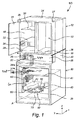
図1は、リソグラフィユニット10(または検査ユニット)などの例示の標的処理マシンの斜視図を概略的に示す。複数のかかるリソグラフィユニット10が、リソグラフィユニットクラスタ(図示せず)を形成するために当接状態で横並びに配置され得る。リソグラフィユニット10は、投影コラム46(図2aおよび図2bを参照)を収容するための真空チャンバ30と(好ましくは下方側部に)、電子機器22を収容するためのキャビネット12と(好ましくは真空チャンバ30の上方に位置決めされる上方側部に)を備える。電子機器22は、真空チャンバ30の内部に収容される投影コラムの部分を含むデバイスを制御するために使用され得る。リニア軸受部材(例えばレール)38が、真空チャンバ30の頂側部32上に設けられて、真空チャンバ30の頂部上へのキャビネット12の位置決めを容易にするための、または真空チャンバ30に対してキャビネット12を前方へと補修位置に移動させるためのガイド機構を形成し得る。この構成では、真空チャンバ30は、その頂部表面上に機器キャビネット12の重量を支持する。
In the drawings, various directions are shown to define the position, orientation and movement of the described object. In the exemplary embodiment shown in the drawings and described herein, X is used in the exemplary embodiment to indicate a longitudinal direction corresponding to the insertion direction of the projection lens arrangement. Prepositions such as “front” and “rear” relate to this longitudinal direction X. Furthermore, Y is used to indicate the transverse direction (in the plane in which the projection lens element extends) that is perpendicular to the longitudinal direction X. During use of the exemplary lithographic unit, vacuum chamber, and cabinet, the longitudinal direction X and the transverse direction Y preferably extend in a plane that is substantially parallel to the horizontal. The terms “left / right” and “lateral” correspond to the lateral direction Y. Z is used to indicate a vertical direction (eg, vertical direction) that is orthogonal to X and Y. The terms “up / down” and “up / down” relate to the vertical direction Z. It should be understood that the inventive concepts discussed herein are not limited to these orientation definitions and preferred orientations.
Lithographic Unit FIG. 1 schematically depicts a perspective view of an exemplary target processing machine, such as lithography unit 10 (or inspection unit). A plurality of such
真空チャンバ30は、真空ケーシング39(外方層)と、支持ケーシング40(中間層)と、キャリアフレーム42を有するキャリアケーシング41(最内領域)とを囲む。投影レンズアセンブリ50が、真空チャンバ30の内側のキャリアフレーム42により収容される。以下、真空チャンバ30および投影レンズアセンブリ50の一実施形態が、図2aおよび図2bを参照としてさらに詳細に説明される。
The
図1は、投影コラム46の投影レンズアセンブリ50部分のみを示す。キャリアケーシング41は、例えば図2aおよび図2bに示されるように投影コラム46全体を収容するように構成される点を理解されたい。投影コラム46のパーツは、電子機器22になど標的処理ユニット10内の他の機器またはデバイスに接続可能である。例えば、図1では、投影レンズアセンブリ50は、導管60、37、37a、37b、および26を介して電子機器22に接続される。導管は、ケーブル、ワイヤ、チューブ、および/またはファイバを含み得る。
FIG. 1 shows only the
投影レンズアセンブリ50は、レンズ素子54を収容するための平面レンズ支持体52と、真空チャンバ30の内部に設けられたコネクタパネル48に向かってレンズ支持体52から離れるように側方におよび上方に導管(60〜64、図3a〜図5aを参照)を案内するための導管ガイド体とを備える。図1および図2aに示されるように、コネクタパネル48は、キャリアケーシング41の内側の側方領域Bに設けられる。好ましくは、コネクタパネル48は、キャリアケーシング41の内方上方部分に機械的に固定される。代替的には、コネクタパネル48は、別の適切な領域においてキャリアケーシング41に装着されてもよい。コネクタパネル48は、投影レンズアセンブリ50と例えばキャビネット12の内部に設けられた電子機器22などの標的処理ユニット10内の他の場所に設けられたソースデバイスおよび/または宛先デバイスとの間に電気接続、光学通信、および/または流体連通を確立するために、導管60〜64の遠位端部に接続するための相補コネクタを備える。この実施形態では、コネクタパネル48およびその相補コネクタは、垂直方向Zに構成される。
The
投影レンズアセンブリ50は、投影レンズアセンブリ50がモジュール式ビーム投影コラム46の一部を形成する位置である動作位置(図2a〜図2bを参照)をとるように、長手方向Xに対して平行である中心軸Aに沿ってキャリアフレーム42内に直線的に挿入可能である。投影コラム46は、真空チャンバ30の内部に収容された標的31を処理(または検査)するために使用される1つまたは複数の処理ビームを発生および操作するように構成される。挿入可能な投影レンズアセンブリ50と、導管60〜64と、コネクタパネル48とを有するこの構成は、投影コラム46のモジュール式の設置とメンテナンスとを一般的に容易にする。
The
図1に示されるように、中間導管37は、コネクタパネル48の後方側から起始し、真空チャンバ30の頂側部32に位置するアクセスポート36へと大体において鉛直方向の軌道を介して真空チャンバ30の内側で案内される。
As shown in FIG. 1, the
中間導管37は、支持ケーシング40とキャリアケーシング41との間に第1の可撓性湾曲中間部分37aを備える。第1の中間導管部分37aは、2つの装着部材またはアンカー34a、34bの間に延在する。第1の中間導管部分37aは、長手方向Xおよび垂直方向Zに少なくとも沿っておよび好ましくは全方向において支持ケーシング40とキャリアケーシング41との間に十分な振動/運動の分断を与える。典型的には、数マイクロメートルの支持ケーシング40とキャリアケーシング41との間の変位が、第1の可撓性部分37aにより容易に減衰され得る。
The
同様に、中間導管部分37は、支持ケーシング40と真空ケーシング39との間に可撓性の湾曲した第2の中間部分37bを備える。第2の中間導管部分37bは、装着部材またはアンカー34aとアクセスポート36との間に延在する。第2の中間導管部分37bは、長手方向Xおよび垂直方向Zに少なくとも沿っておよび好ましくは全方向において支持ケーシング40と真空ケーシング39との間に十分な振動/運動の分断を与える。典型的には、数マイクロメートルの支持ケーシング40と真空ケーシング39との間の変位が、第2の中間導管部分37bにより容易に減衰され得る。
Similarly, the
以降では、コネクタパネル48、中間導管部分37、第1の装着部材34a、第1の中間導管部分37a、第2の装着部材34b、第2の中間導管部分37b、およびアクセスポート36によって形成されるアセンブリは、「中間導管アセンブリ」108と呼ばれる。
Hereinafter, formed by
真空チャンバ30は、標的31に対して実施される処理方法の実行に寄与する様々な機器、デバイス、および/または構成要素を含み得るまたは収容し得る。かかる機器/デバイス/構成要素は、それらの固有の制振および/または動き保証システムを備えてもよく、あるいは外部の機械的振動を被りにくくてもよい。また、かかる機器/デバイス/構成要素は、例えば電力、初期化/制御信号、もしくは冷却流体を受領するために、および/または測定信号もしくは他のフィードバックデータを送出するためになど、1つまたは複数の導管を介してキャビネット12の内部の対応する電子機器22に接続されてもよい。その一例が、投影コラム46の下方に標的31(例えばウェーハ)を位置決めするための標的位置決めシステムである。さらに、電子機器22またはキャビネット12内の他の機器は、標的処理ユニット10の外部の(例えば下方に配置された)機器/デバイス/構成要素に接続されてもよい。
The
以降では、電子機器22にまたはキャビネット12内の他の機器に接続される機器/デバイス/構成要素は、「さらなる機器」と呼ばれる。さらなる機器に電子機器22またはキャビネット12内の他の機器を接続する制御ケーブル、導管、および/または配線は、「さらなる導管」と呼ばれる。
Hereinafter, equipment / devices / components connected to the
頂側部32では、真空チャンバ30が、連結壁部35を備える凹状セクション33を備える。連結壁部35は、好ましくは頂側部32の全幅にわたって延在し、典型的には垂直方向Zに沿って配向され、その一方で長手方向Xに向く(逆方向に)。連結壁部35は、真空チャンバ30から起始する中間導管37を受けるおよび通過させるためのアクセスポート36を備える。中間導管37は、その後キャビネット12の内部に案内され、キャビネット12内に設けられた電子機器22に接続される。代替的にはまたは追加的には、リソグラフィユニット10は、複数のアクセスポートを、および/または真空チャンバ30の頂側部32の付近の後方側部に後方連結壁部を備えてもよい。この後方連結壁部は、中間導管37の一部分を通過させるためのさらなるアクセスポートを、または真空チャンバの内部に収容されたさらなる機器/デバイス/構成要素に帰属する他の導管およびワイヤを有してもよい。
At the
キャビネット12は、壁部により形成された、およびキャビネット12の内部へのアクセスを与える開口部を有する前方側部13を有する、閉鎖可能ケーシングを典型的には備える。前方側部13は、封止的にこの開口部を覆うための2つのドア15を備える。壁部およびキャビネットドア15は、開口のないパネルを備え、これらのパネルは、直方体形状を形成するように気密的に相互連結される。キャビネット12は、内部を密閉し、1つまたは複数のラック18を収容する。プレナム16が、開口部とラック18の前方との間に形成される。各ラック18は、様々な電子構成要素を備える電子機器22を収容するための複数の棚20を担持する。かかる電子構成要素は、任意の個数の電気供給源、集積回路、メモリモジュール、磁気記憶媒体、光学記憶媒体、もしくは固体記憶媒体、オーディオハードウェア、および/またはビデオハードウェアを含み得るが、それらに限定されない。
The
キャビネット12は、典型的には、空気循環器および熱交換器構成体を備える空気−流体間冷却機構などの冷却機構を備える。図1に示される実施形態では、空気循環器および熱交換器は、キャビネット12の後方側部に位置決めされた別個のクーラーフレーム24内に取り付けられる。ケーシングおよびクーラーフレーム24は、レール38の上に別個に取り付け可能であり、レール38に沿って再位置決め可能である。
The
プレナム16は、垂直方向Zに沿って延在するキャビネット導管26(例えば電気ケーブル、冷却流体を有するチューブ、または中間導管37など)を収容するために、ケーシングの側方(左)壁部に鉛直方向壁部部分25を備える。
The
図1に示されるリソグラフィユニット10の実施形態では、ケーシングの対向側の側方(右)壁部に配置された鉛直方向凹部27がさらに提供される。この場合に、鉛直方向凹部27は、右壁部付近にプレナム16の側方部分を形成する矩形直方体空部を画成する。鉛直方向凹部27は、実質的に右壁部全体に沿って鉛直方向に延在する。側方鉛直方向凹部27は、ケーシングの内部を、特にプレナム16を通り循環する冷却空気流を妨げることなく対応する機器22におよび対応する機器22から信号および/または電力導管26を送ることを可能にする。他の実施形態では、凹部27は、代替的にまたは追加的にケーシングの左壁部上に設けられてもよい。
In the embodiment of the
鉛直方向壁部部分25(および/または鉛直方向凹部27)は、鉛直方向壁部部分25の所望の部分に沿ってキャビネット導管26を保持するための固定手段を備える。それぞれの機器位置にて、キャビネット導管26は、対応する電子機器ユニット22の前方側部との接続部を形成するために鉛直方向壁部部分25(および/または鉛直方向凹部27)から分岐する。
The vertical wall portion 25 (and / or the vertical recess 27) includes a securing means for holding the
鉛直方向壁部部分25(および/または凹部27)の底部付近にてならびにプレナム16の側方側部にて、キャビネット12は、キャビネット12の中に/から外にキャビネット導管26を案内するための床部開口28を備える。
真空チャンバ
図2aは、標的処理ユニット10の一実施形態における真空チャンバ30の正面図を示す。真空チャンバ30は、真空環境(典型的には10-3バールまたはそれ未満)内での標的31の処理を可能にするために、封止可能であり内部に真空を印加するように構成された真空ケーシング39を備える。真空チャンバ30は、標的31と、真空チャンバ30の内側で標的31を処理するための投影コラム46とを収容するように構成される。真空チャンバ30は、真空ケーシング39(外方層)と、支持ケーシング40(中間層)と、キャリアフレーム42を有するキャリアケーシング41(最内領域)とを備える。投影レンズアセンブリ50を有する投影コラム46は、真空チャンバ30の内側でキャリアフレーム42により収容および支持され、キャリアケーシング41の内部に画成された空間内に配置される。荷電粒子ビームレットを使用する用途では、キャリアケーシング41は、磁気遮蔽材料から作製されることが好ましい。
Near the bottom of the vertical wall portion 25 (and / or recess 27) and at the lateral sides of the
Vacuum Chamber FIG. 2 a shows a front view of the
キャリアケーシング41およびキャリアフレーム42は、典型的には、例えば懸吊ベース43に連結される懸吊部材44(例えば板ばね)により、支持ケーシング40の内部におよび支持ケーシング40に対して可動的に懸吊される。懸吊ベース43は、複数の剛性のしかし側方にヒンジ動作可能な懸吊ロッド45によりキャリアケーシング41に可動的に相互連結される。コネクタパネル48およびその相補コネクタ49は、キャリアケーシング41の内側に設けられる。コネクタパネル48は、その面法線が、長手方向Xに沿っておよび長手方向Xとは逆方向に配向され、投影コラム46に隣接して配置された状態で、側方領域Bにおいて垂直方向Zに沿って鉛直方向に配置される。中間導管37は、コネクタパネル48の後方側部から起始し、キャリアケーシング41の開口を介して第1の可撓性湾曲中間部分37aに沿って支持ケーシング40まで案内される。支持ケーシング40とキャリアケーシング41との間の第1の可撓性湾曲中間部分37aは、長手方向Xおよび垂直方向Zに少なくとも沿って支持ケーシング40とキャリアケーシング41との間に十分な振動/運動の分断を与える。中間導管37は、支持ケーシング40と連結壁部35上に配置されたアクセスポート36との間に第2の可撓性湾曲中間部分37bをさらに備える。
投影コラム
図2bは、リソグラフィユニット10の一実施形態における投影コラム46の概略図を示す。投影コラム46は、真空チャンバ30の内部に収容された標的31を処理(または検査)するために使用される1つまたは複数の処理ビーム47を発生および操作するように構成される。投影コラム46は、図2bに示されるようにモジュール式に実装され得る。光学素子が、リソグラフィユニット10から個別に除去され得るモジュールへとグループ化される。モジュール式サブシステムは、荷電粒子ビーム源92とビームコリメータアレイ94とを含む照明光学モジュール90、開口アレイとコンデンサレンズアレイ98とを含むコンデンサレンズモジュール96、ビームレットブランカアレイ102を含むビーム切替えモジュール100、およびレンズ素子54を有する投影レンズアセンブリ50を備え得る。投影レンズ素子は、参照数字54で一体的に示されるビームストップアレイ、ビーム偏向器アレイ、および投影レンズアレイを備える。ビームストップアレイは、ビームレットブランカアレイ102によりブランキング偏向を受けているビームレット47を阻止するための、および前記ビームブランカアレイ102によりブランキング偏向を受けていないビームレット47を通過させるための開口アレイを備えてもよい。ビーム偏向器アレイは、好ましくは前記ビームブランカアレイ102の下流に配置される。投影レンズアレイは、投影レンズアセンブリ50の下方エッジの付近に平面レンズ電極を備える。各平面レンズ電極は、ビームレット47を通過させ合焦させるためのレンズ開口アレイを備え、レンズ開口は、鉛直方向に対応するビームレット操作要素の開口と整列される。キャリアフレーム42は、対応するモジュール50、90、96、100のための収容空間をそれぞれが与える複数の高さを有する階段状プロファイルの支持領域を備え得る。
投影レンズアセンブリ
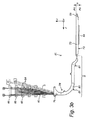
図3aは、キャリアフレーム42内に位置決めするように構成された投影レンズアセンブリ50の上面図を概略的に示す。投影レンズアセンブリ50の構成要素は、リソグラフィユニット10内に設けられたソースデバイスおよび/または宛先デバイスとの間で電力の伝達、制御信号の通信、冷却流体の連通、および/または他の電気接続もしくは流体連通を必要とする場合がある。一方の端部では、導管60は、投影レンズアセンブリ50の構成要素に接続される。導管60の遠位端部65に設けられたコネクタ66は、コネクタパネル48の前方側部に設けられた相補コネクタ49に接続可能である。
The
Projection Column FIG. 2 b shows a schematic diagram of the
Projection Lens Assembly FIG. 3 a schematically shows a top view of a
投影レンズアセンブリ50は、レンズ素子54を収容するための平面レンズ支持体52と、レンズ支持体52の後方エッジ58から起始する複数の導管60〜64と、キャリアケーシング41の内方側部上の側方領域Bに設けられたコネクタパネル48に向かってレンズ支持体52から離れるように側方におよび上方に導管60〜64を案内するための導管ガイド体70とを備える。この実施形態では、レンズ支持体52は、機械的剛性のおよび磁気遮蔽性の材料から作製された正五角形支持プレートにより形成される。多角形支持プレート52は、長手方向Xに対して共に平行である2つの相対側方エッジ56、57を有する。後方プレートエッジ58は、長手方向Xに対して逆方向に向く。2つの残りの前方エッジは、前方突出角部を有する先端部を形成する。
The
多角形支持プレート52は、3つの実質的に球状の当接部材55を備える。代替的には、当接部材55は、任意の適切な形状(例えば裁頭回転楕円体、扁平楕円体など)を有してもよい。レンズ支持体52は、ビーム源92から発せられる(例えば投影コラム46により発生される)ビーム(レット)47を操作するために1つまたは複数のレンズ素子54を収容するためのレンズ切欠部53を備える。投影コラム46の投影レンズアセンブリ50および他のモジュール(例えば照明光学モジュール90、コンデンサレンズモジュール96、および/またはビーム切替えモジュール100など)は、当接部材55が整列表面に対接して位置決めされる場合に、投影コラム46のビーム投影軸がレンズ支持体52内のレンズ素子54の(温度)中心と実質的に一致することになるように、キャリアフレーム42内に挿入されることになる。
導管ガイド体70は、レンズ支持体52の後方エッジ58に沿って設けられ、側方導管ガイド部分72(第1のガイド部分とも呼ばれる)と鉛直方向導管ガイド部分78(第2のガイド部分とも呼ばれる)とを備える。第1のガイド部分72は、機械的剛性のおよび磁気遮蔽性の材料から作製された大体において四辺形の支持プレート73を備える。この実施形態では、四辺形支持プレート73は、面P内に配置された、および長手方向Xに対して共に平行である2つのさらなる相対側方エッジ74、75を備える矩形プレートを形成する。右のさらなる相対側方エッジ75は、相対側方エッジ57の平行延長部を形成する。
A
ガイドホイール59が、長手方向Xに沿ったキャリアフレーム42内へのレンズ支持体52の位置決めを容易にすると共に、面Pと同一高さに支持体52を保持するために、相対側方エッジ56、57に沿って設けられる。
A
図3aの導管ガイド体70は、側方領域Bにスレッジ80をさらに備える。スレッジ80は、第2のガイド部分78と、場合によっては第1のガイド部分72の一部を備える。導管60〜64は、スレッジ80の内部に収容され、横方向Yに沿った平坦な局所的平行構成から垂直方向Zに沿った平坦な局所的平行構成へと湾曲される。スレッジ80の外方輪郭は、長手方向Xに沿って実質的に線対称である。導管60〜64は、長手方向Xに対して平行に延在する傾斜エッジ79にてスレッジ80から起始する。各導管60〜64は、遠位導管端部65に導管コネクタ66を備える。これらの導管コネクタ66は、コネクタパネル48上に設けられた相補コネクタ49に導管60〜64を接続するために構成される。キャリアフレーム42は、スレッジ80などの導管ガイド体70の少なくとも一部に対して相補的な形状を有する切欠部82を側方領域Bに備えてもよい。
The conduit guide
図3bは、正の長手方向に沿って見た、図3aに示される投影レンズアセンブリ50のための実施形態の背面図を示す。ここでは、導管ガイド体の外方外周部が、長手方向Xに沿って実質的に線対称であり得ることが図示される。図3bに示されるように、四辺形支持プレート73は、第1の面P1により(垂直方向Zに沿って)上方から画定され、第2の面P2により(垂直方向Zに沿って)下方から画定される。第1の面P1および第2の面P2は、相互に平行であり、面Pに対してそれぞれ平行である。第1の面P1と第2の面P2との間の典型的な距離、すなわち投影レンズアセンブリ50用の四辺形支持プレート73の典型的な高さhは、3ミリメートル〜10ミリメートルの範囲内であり、好ましくは約5ミリメートルである。横方向における支持プレート52、73の典型的な寸法は、約15〜25cmであり得る。
FIG. 3b shows a rear view of the embodiment for the
図3bは、(この実施形態では四辺形支持プレート73を備える)第1のガイド部分72内に収容された導管60〜64が、導管60〜64が四辺形(矩形)支持プレート73から側方に起始する側方領域Bまでにおいて第1の面P1と第2の面P2との間に限定された状態に留まるのを示す。側方領域Bでは、導管60〜64は、上方に湾曲したスレッジ80を備える第2のガイド部分78に進入し、傾斜エッジ79までスレッジ80を縦走する。
FIG. 3b shows that the conduits 60-64 housed in the first guide portion 72 (comprising a
図3bは、スレッジ80が、キャリアフレーム42内へのスレッジ80の位置決めを容易にするためのスレッジガイド部材81を備え得るのを示す。スレッジガイド部材81は、スレッジ80に沿っておよび長手方向Xに対して平行に直線的に延在する。図示される実施形態では、投影レンズアセンブリ50は、投影コラム46の最下モジュールを形成する。したがって、投影レンズ素子54は、第2の面P2を越えて下方に短距離にわたり突出させられ得る。
FIG. 3 b shows that the
図4は、支持表面の層状スタックを備える、および大体において矩形状U字形状(垂直方向Zに沿って見た場合に)を形成する例示のキャリアフレーム42を示す。キャリアフレーム42は、投影コラム46および投影レンズアセンブリ50のためのインサートを備える。これらのインサートは、それぞれのモジュールのための整列表面および支持表面(例えばさらなるレール83)を備える。キャリアフレーム42は、相互に対して角度方向にオフセットされた3つの平坦整列表面を備える。キャリアフレーム42は、キャリアフレーム42内にレンズ支持体52を挿入する最中にこのレンズ支持体52を支持および案内するために、長手方向Xに沿って配置されたさらなるレール83を備える。レンズ支持体52上のガイド部材59(例えばホイール)が、さらなるレール83と協働するように適合化される。
FIG. 4 shows an
レンズ支持体52は、長手方向Xに対して平行である中心軸Aに沿ってキャリアフレーム42内に挿入可能である。キャリアフレーム42内に配置されると、3つの当接部材55のそれぞれが、3つの整列表面の中の対応する1つに対接して並んで位置する。当接部材55が対応する整列表面と接触状態に留まることを確保するために、力が、整列表面に対して当接部材55を押し当てるように前記モジュールに対して印加されてもよい。
The
導管60〜64の遠位端部65に設けられたコネクタ66は、鉛直方向に配置されたコネクタパネル48の前方側部に設けられた相補コネクタ49に接続可能である。
The
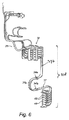
図5aは、一実施形態による投影レンズアセンブリ50の頂部部分の斜視図を示す。五角形支持プレート52および矩形支持プレート73は、導管構成を示すために保護カバープレートが除去された状態で図示される。投影レンズアセンブリ50は、ビーム操作要素の鉛直方向スタックにより形成される投影レンズ素子54を備える。例えば、投影レンズ素子54は、ビームブランカによるブランキング偏向を有する荷電粒子ビームレットを阻止し、前記ビームブランカによるブランキング偏向を有さない荷電粒子ビームレットを通過させるための開口アレイを備えるビームストップアレイと、伝達された荷電粒子ビームレットに通路を与えるための貫通開口部に整列されたレンズ穴アレイをそれぞれが備える複数の電極(好ましくは投影レンズアセンブリの下流遠位エッジにより画定される面の中または付近に配置される)と、偏向器ユニット(好ましくは前記電極の上流におよび前記ビームブランカの下流に配置される)とのいずれかまたは全てを備えてもよい。
FIG. 5a shows a perspective view of the top portion of the
かかるレンズ素子54のそれぞれが、リソグラフィユニット10内に設けられたソースデバイスおよび/または宛先デバイスとの間で電力の伝達、制御信号の通信、冷却流体の連通、および/または他の電気接続もしくは流体連通を必要とし得る。例えば、ビームストップアレイは、冷却導管64を介してビームストップアレイに冷却流体を供給する(およびビームストップアレイから冷却流体を放出する)ために使用される外部冷却構成体による冷却を必要とし得る。レンズ電極は、レンズ電極間に電位差を印加するように構成された電源を有する導電導管60を使用した接続を必要とし得る。ビーム偏光ユニットは同様に、信号導管60を介して、電気接続を必要とする。レンズ素子54の他の構成要素は、例えばレンズ素子54の上または周囲に設けられた送りアライメントセンサ69に電力を伝達する導管62を使用して遠く離れた源からの電力を必要とし得る。かかるセンサ69は、さらなる信号導管(例えば光ファイバ)を介した制御およびフィードバック通信をさらに必要とし得る。
Each
様々な導管60〜64(ケーブル/ワイヤ/チューブ/ファイバ)が、面Pに対して平行である空間構成にしたがって投影レンズ素子54に接続される。投影レンズ素子54は、五角形支持プレート52中に設けられた円形レンズ切欠部53の内部のレンズキャリアリング68によって懸吊される。レンズキャリアリング68は、比較的低い熱膨張率を有する材料を備えてもよく、および/または閉ループ(能動的フィードバック)位置制御(例えば光学および/または容量アライメントセンサ69を使用した)により熱的に安定化されてもよい。導管60〜64は、レンズ支持体52上の様々な位置から様々な方向において、および円形レンズ切欠部53の外周部に沿ってレンズキャリアリング68および/またはレンズ素子54に接続される。五角形支持プレート52の典型的な横方向寸法は、五角形支持プレート52の典型的な高さhよりも実質的に大きい。五角形支持プレート52は、円形レンズ切欠部53の外周部に沿って1つまたは複数の空部を画定する。これらの1つまたは複数の空部は、導管60〜64が後方エッジ58に向かって五角形支持プレート52を通りレンズ切欠部53の周囲の様々な初期位置から湾曲状に案内されるための余地を与える。結果として、導管60〜64は、レンズ切欠部53の外周部に沿って多方向からレンズ素子54に接続可能である一方で、導管60〜64は、後方エッジ58にまでそれらの経路に沿って交差する必要はない。
Various conduits 60-64 (cable / wire / tube / fiber) are connected to the
側方エッジ57に沿って、五角形支持プレート52は、五角形支持プレート52を越え、レンズ素子54の付近の円形レンズ切欠部53の矩形開口から起始する洗浄剤供給チューブ67をさらに備えてもよい。この供給チューブ67は、電子ビーム処理の結果として上述のレンズ素子54上に蓄積した汚染堆積物を除去するために、レンズ素子54への外部洗浄剤源(図示せず)からの反応性薬剤(例えばイオンおよびラジカルを含むプラズマ流など)の供給を可能にする。供給チューブ67は、扁平矩形断面形状を有する。
Along the
図5aに示されるようにおよび図3bを参照として本明細書内で上述した実施形態と同様に、五角形支持プレート52は、第1の面P1および第2の面P2により鉛直方向に画定される。導管60〜64は、後方エッジ58に向かって合流され、好ましくは第1の面P1と第2の面P2との間に限定される平行(すなわち非交差)平面構成で後方エッジ58から起始する。後方エッジ58から、導管60〜64は、四辺形支持プレート73(第1のガイド部分72の一部)に進入する。第1の面P1と第2の面P2との間でやはり鉛直方向に限定される四辺形支持プレート73の内部では、導管60〜64は、側部(ここでは正のY方向に沿って示される)への屈曲部を有する局所的平行構成で、および五角形支持プレート52の第1の側部エッジ56により画定される側方領域Bに向かって湾曲状に案内される。この実施形態では、第1の側方エッジ56は、四辺形支持プレート73の第1のさらなる側方エッジ74の延在部を形成する。
As shown in FIG. 5a and similar to the embodiments described hereinabove with reference to FIG. 3b, the
導管60〜64は、大体において側方方向Yに沿って配向された局所的平行構成で第1のさらなる側方エッジ74から起始する。この場合に、導管60〜64は、本明細書で上述されるように第2のガイド部分78に進入する。
The conduits 60-64 originate from the first further
他の実施形態では、導管60〜64の中の1つまたは複数が、いずれの位置においても局所的平行で構成される代わりに、レンズ支持体52(例えば五角形支持プレート)または第1のガイド部分72(例えば四辺形支持プレート73)の中のいくつかの箇所で交差するように構成されてもよい。これは、導管を収容するために必要とされる高さを増大させ得ることにより、第1の面P1および第2の面P2により画定される領域(高さh)を上回る収容高さを結果的にもたらし得るため望ましくない。 In other embodiments, instead of one or more of the conduits 60-64 being configured to be locally parallel at any location, a lens support 52 (eg, pentagonal support plate) or first guide portion. 72 (for example, the quadrilateral support plate 73) may be configured to intersect at some points. This can result in an accommodation height that exceeds the area defined by the first surface P1 and the second surface P2 (height h) by increasing the height required to accommodate the conduit. Is undesirable because it can result in
図5bは、図5aの投影レンズアセンブリ50の斜視背面図を示す。五角形支持プレート52および矩形支持プレート73の下方側部が、(例えば下方に配置された標的31に対して)電磁遮蔽をもたらす閉鎖表面を形成する。
FIG. 5b shows a perspective rear view of the
上記の説明は、限定ではなく例示として意図される。本発明の代替的なおよび均等な実施形態は、以下に示す特許請求の範囲から逸脱することなく想起され得るおよび実施に移され得る点が、当業者には明らかになろう。 The above description is intended to be illustrative rather than limiting. It will be apparent to those skilled in the art that alternative and equivalent embodiments of the present invention can be devised and put into practice without departing from the scope of the claims set forth below.
例えば、本発明者らは、本明細書で上述されたモジュール式投影アセンブリのための空間構成が、好ましくは投影ビームに短い焦点距離をもたらすために垂直(鉛直)方向において非常に薄い(例えば図3bおよび図5aに示されるような高さhを有する)投影レンズアセンブリで適用される場合に特に有利である点に気付いた。かかる薄い投影モジュールは、所要の厚さの境界内に導管を保持する役割を果たす導管およびガイド手段の平坦構成から利益を被る。しかし、投影レンズの代替としてまたは追加としてのいずれかにおいて他のビーム操作構成要素を有し得る投影アセンブリまたはモジュールでこの提案される構成を適用することが可能である。したがって、本明細書で上述されたが他のビーム操作構成要素を収容するように構成されたモジュール式投影要素アセンブリは、本コンテクスト内でそれ自体において本質的に独創的なものと考えられ、個別の特許出願の対象となり得る。これに対応して、本明細書で説明され特許請求されるような「投影レンズアセンブリ」、「レンズ支持体」、および「レンズ素子」という用語は、それぞれより一般的に「ビーム操作モジュールアセンブリ」、「ビーム操作要素支持体」、および「ビーム操作要素」と言い換えられてもよい。
さらなる態様
半導体産業では、高い精度および信頼性を有するより小さな構造体を製造することへの高まり続ける要望が存在する。リソグラフィシステムでは、この要望は、結果として位置決めおよび配向に対する極めて高い要求をもたらす。製造工場環境および/または電気回路において他のマシンにより引き起こされる外部振動は、リソグラフィ装置内における位置決め精度に対してマイナスの影響を有し得る。同様に、例えばステージ移動などにより引き起こされるリソグラフィ装置内の振動が、かかる精度に対してマイナスの影響を有し得る。
For example, the inventors have found that the spatial configuration for the modular projection assembly described hereinabove is very thin in the vertical (preferably vertical) direction, preferably to provide a short focal length for the projection beam. It has been found that it is particularly advantageous when applied in a projection lens assembly (having a height h as shown in 3b and FIG. 5a). Such a thin projection module benefits from a flat configuration of conduit and guide means that serve to hold the conduit within the required thickness boundary. However, it is possible to apply this proposed configuration in a projection assembly or module that may have other beam manipulation components either as an alternative or in addition to the projection lens. Thus, a modular projection element assembly described above in this specification but configured to accommodate other beam steering components is considered inherently unique in its own right within this context. Patent application. Correspondingly, the terms “projection lens assembly”, “lens support”, and “lens element” as described and claimed herein are each more generally referred to as “beam manipulation module assembly”. , “Beam manipulation element support” and “beam manipulation element”.
Further Aspects In the semiconductor industry, there is an ever increasing desire to produce smaller structures with high accuracy and reliability. In lithographic systems, this desire results in very high demands on positioning and orientation. External vibrations caused by other machines in the factory environment and / or electrical circuits can have a negative impact on positioning accuracy within the lithographic apparatus. Similarly, vibrations in the lithographic apparatus caused, for example, by stage movements can have a negative effect on such accuracy.
真空チャンバの内部のさらなる機器(すなわち標的処理機器)ならびにそれらの対応するケーブルおよび導管のコンパクトな構成と、制御およびモニタリングキャビネットの内部の対応する機器に真空処理チャンバの内部のさらなる機器を接続するために必要とされる中間ケーブルおよび導管の構成とを提供することが、一般的に望ましいものとなり得る。 To connect additional equipment inside the vacuum processing chamber to the compact equipment of the internal equipment of the vacuum chamber (ie the target processing equipment) and their corresponding cables and conduits and corresponding equipment inside the control and monitoring cabinet It may generally be desirable to provide the required intermediate cable and conduit configurations.
ケーブルおよび導管は、好ましくは以下の3つの目的の中の1つまたは複数に寄与するように構成される。 The cables and conduits are preferably configured to contribute to one or more of the following three purposes.
各処理ユニットの内側層が、各ユニットの内部に収容されたモジュールおよび/またはデバイスの大多数に対する前方側アクセス性を高めることによって、最小限のフットプリントを有する個別の処理ユニットの横並び構成を可能にする。 The inner layer of each processing unit allows side-by-side configuration of individual processing units with minimal footprint by increasing forward accessibility to the majority of modules and / or devices contained within each unit To.
各処理ユニットの内部のモジュール/デバイスおよび導管のモジュール式構成が、長手方向に沿った可動性を促進すると共にこの方向に沿った他のモジュール/デバイスの障害を削減するようにモジュール/デバイスと対応するケーブルとを形成および位置決めすることによって、かかるモジュール/デバイスおよび導管の個別の交換を容易にする。 Modular configuration of modules / devices and conduits inside each processing unit accommodates modules / devices to facilitate mobility along the longitudinal direction and reduce the obstacles of other modules / devices along this direction Forming and locating cables to facilitate the individual exchange of such modules / devices and conduits.
処理ユニットの内部の導管のグループ構成が、モジュール/デバイスに対して必要とされる程度までその特定のモジュール/デバイスごとの個別の運動/振動の分断を促進するために十分に機械的に分離される。 The grouping of conduits inside the processing unit is sufficiently mechanically separated to facilitate the division of individual motion / vibration for that particular module / device to the extent required for the module / device. The
処理ユニットの内部の導管のグループ構成が、投影光学コラムに帰属するモジュール/デバイスにおよび帰属しないモジュール/デバイスに個別の導管経路を与え、その結果として削減されたまたはさらには最小限の個数の非コラム関連モジュール/デバイスに帰属する導管により占められる投影光学コラム用の真空空間が得られることによって、モジュールコンセプトを支援する。 The grouping of conduits inside the processing unit provides separate conduit paths for modules / devices belonging to the projection optical column and modules / devices not belonging to the projection optical column, resulting in a reduced or even minimal number of non-channels. Supports the module concept by providing a vacuum space for the projection optical column occupied by the conduits belonging to the column related modules / devices.
上述の目的の中の1つまたは複数を満たすために、標的処理ユニットが、本明細書において以下で説明されるように中間導管アセンブリおよび鉛直方向ケーブルガイドケーシングの少なくとも一方を備えるケーブル分配構成体を備えてもよい。 To meet one or more of the above objectives, the target processing unit comprises a cable distribution arrangement comprising at least one of an intermediate conduit assembly and a vertical cable guide casing as described herein below. You may prepare.
リソグラフィユニット内の振動を可能な限り軽減することが望ましい。 It is desirable to reduce vibrations in the lithography unit as much as possible.
したがって、一態様によれば、電子機器を着脱可能に接続するためのアクセスポートと、投影コラムの1つまたは複数のパーツを着脱可能に接続するためのコネクタパネルとを備える標的処理ユニットが提供される。アクセスポートは、標的処理ユニットの外部に少なくとも部分的に配置され得る。コネクタパネルは、標的処理ユニットの内部に配置され得る。アクセスポートおよびコネクタパネルは、1つまたは複数の中間導管を介することにより振動/運動が分断されるように接続される。 Thus, according to one aspect, a target processing unit is provided comprising an access port for removably connecting an electronic device and a connector panel for removably connecting one or more parts of a projection column. The The access port may be located at least partially outside the target processing unit. The connector panel may be disposed inside the target processing unit. The access port and connector panel are connected such that vibration / motion is decoupled by way of one or more intermediate conduits.
標的処理ユニットは、例えば本明細書で上述された実施形態と同様のリソグラフィユニットにより形成され得る。投影コラムの1つまたは複数のパーツは、荷電粒子ビーム源とビームコリメータアレイとを備える照明光学モジュール、開口アレイとコンデンサレンズアレイとを備えるコンデンサレンズモジュール、ビームレットブランカアレイを備えるビーム切替えモジュール、および/またはレンズ素子を有する投影レンズアセンブリを含み得る。投影レンズアセンブリのレンズ素子は、ビームストップアレイ、ビーム偏向器アレイ、および/または投影レンズアレイを含み得る。 The target processing unit may be formed, for example, by a lithographic unit similar to the embodiments described herein above. The one or more parts of the projection column comprise an illumination optics module comprising a charged particle beam source and a beam collimator array, a condenser lens module comprising an aperture array and a condenser lens array, a beam switching module comprising a beamlet blanker array, and A projection lens assembly having lens elements may be included. The lens elements of the projection lens assembly may include a beam stop array, a beam deflector array, and / or a projection lens array.
アクセスポートは、標的処理ユニットの外部からアクセス可能であり、または投影コラムが位置する標的処理ユニットの部分の外部の雰囲気に投影コラムを露出させることなく少なくともアクセス可能である。これにより、電子機器は、典型的には投影コラムを囲む真空環境を犠牲にすることなくアクセスポートに接続され得る。 The access port is accessible from outside the target processing unit, or at least accessible without exposing the projection column to the atmosphere outside the portion of the target processing unit where the projection column is located. This allows the electronics to be connected to the access port without sacrificing the vacuum environment typically surrounding the projection column.
標的処理マシン内のコネクタパネルは、一方では投影コラムのパーツ間の、および他方では電子機器間の着脱可能な接続(例えばおよび電気信号または光学信号接続)をもたらす。この接続を実現するための物理的部分は、例えばコネクタパネル、アクセスポート、および中間導管を介して経路設定され得る。 Connector panels in the target processing machine provide detachable connections (eg, and electrical or optical signal connections) on the one hand between the parts of the projection column and on the other hand between the electronics. The physical part for realizing this connection can be routed, for example, via connector panels, access ports, and intermediate conduits.
導管は、ケーブル、ワイヤ、チューブ、および/またはファイバを含み得る。導管は、データ通信(電気的および/または光学的)、配電、および/または冷却流体の輸送のために使用され得る。 The conduit may include cables, wires, tubes, and / or fibers. The conduit may be used for data communication (electrical and / or optical), power distribution, and / or transport of cooling fluid.
アクセスポートは、例えばアクセスポートに近い電子機器または他の機器内のファンまたは他の可動要素を起源とする機械振動を被りがちであり得る。機械振動は、アクセスポートに電子機器を接続する導管を介してまたはアクセスポートに(直接的にまたは間接的に)接続された機械構造体を介してアクセスポートに伝達され得る。 An access port may be prone to mechanical vibrations originating from, for example, fans or other movable elements in electronic equipment or other equipment close to the access port. Mechanical vibrations can be transmitted to the access port via a conduit connecting electronics to the access port or via a mechanical structure connected (directly or indirectly) to the access port.
コネクタパネルからアクセスポートを振動/運動上において分断することにより、投影コラムが最も影響を被りやすいリソグラフィ装置内での位置決め精度に対するアクセスポートにおける機械振動のマイナスの影響が、最小限に抑えられるかまたはさらには解消され得る。中間導管を介したコネクタパネルへのアクセスポートの振動/運動が分断された接続は、結果として、投影コラムのパーツ同士が1つまたは複数の導管によりコネクタパネルに接続される場合に、投影コラムの位置決め精度がマイナスの影響を被らないように、振動の十分な減衰をもたらす。 By decoupling the access port from the connector panel in vibration / motion, the negative impact of mechanical vibrations in the access port on the positioning accuracy in the lithographic apparatus where the projection column is most affected is minimized or Furthermore, it can be eliminated. The disconnected connection / vibration of the access port to the connector panel via the intermediate conduit results in the projection column being moved when the parts of the projection column are connected to the connector panel by one or more conduits. Sufficient vibration damping is provided so that the positioning accuracy is not negatively affected.
一実施形態では、中間導管は、アクセスポートとコネクタパネルとの間に振動/運動の分断をもたらすように構成された1つまたは複数の湾曲状可撓性中間導管部分を備え得る。 In one embodiment, the intermediate conduit may comprise one or more curved flexible intermediate conduit portions configured to provide vibration / motion disruption between the access port and the connector panel.
一実施形態では、標的処理ユニットは、電子機器を収容するためのキャビネットを備えることが可能である。標的処理ユニットは、投影コラムを収容するため真空チャンバをさらに備えることが可能である。投影コラムは、標的に向かうビームを発生させる、成形する、および配向するように構成され得る。投影レンズアセンブリなどの投影コラムの1つまたは複数のパーツが、1つまたは複数の導管を介して電子機器に通信接続可能であり得る。真空チャンバは、真空チャンバ内に真空環境を与えるように構成された真空ケーシングを備えることが可能である。真空チャンバは、キャリアケーシングを支持するように構成された真空ケーシング内の支持ケーシングをさらに備えることが可能である。真空チャンバは、投影コラムを支持するように構成された支持ケーシング内のキャリアケーシングをさらに備えることが可能である。標的処理ユニットは、1つまたは複数の導管を少なくとも部分的に備える中間導管アセンブリをさらに備えることが可能である。中間導管アセンブリは、キャリアケーシングの内方側部に装着されたコネクタパネルを備えることが可能である。中間導管アセンブリは、キャリアケーシングの外方側部に連結された第2の装着部材をさらに備えることが可能である。中間導管アセンブリは、コネクタパネルから起始し第2の装着部材に案内される1つまたは複数の中間導管をさらに備えることが可能である。中間導管アセンブリは、支持ケーシングの内方側部に装着された第1の装着部材をさらに備えることが可能である。1つまたは複数の中間導管の第1の可撓性中間導管部分が、第1の装着部材と第2の装着部材との間に延在し得る。中間導管アセンブリは、真空ケーシングの外方側部に装着されたアクセスポートをさらに備えることが可能である。1つまたは複数の中間導管の第2の可撓性中間導管部分は、第1の装着部材とアクセスポートとの間に延在し得る。 In one embodiment, the target processing unit may comprise a cabinet for housing electronic equipment. The target processing unit can further comprise a vacuum chamber to accommodate the projection column. The projection column can be configured to generate, shape, and orient the beam toward the target. One or more parts of the projection column, such as a projection lens assembly, may be communicatively connected to the electronics via one or more conduits. The vacuum chamber can comprise a vacuum casing configured to provide a vacuum environment within the vacuum chamber. The vacuum chamber can further comprise a support casing within the vacuum casing configured to support the carrier casing. The vacuum chamber can further comprise a carrier casing in a support casing configured to support the projection column. The target processing unit may further comprise an intermediate conduit assembly that at least partially comprises one or more conduits. The intermediate conduit assembly can comprise a connector panel mounted on the inner side of the carrier casing. The intermediate conduit assembly can further comprise a second mounting member coupled to the outer side of the carrier casing. The intermediate conduit assembly may further comprise one or more intermediate conduits that originate from the connector panel and are guided to the second mounting member. The intermediate conduit assembly may further comprise a first mounting member mounted on the inner side of the support casing. A first flexible intermediate conduit portion of the one or more intermediate conduits may extend between the first mounting member and the second mounting member. The intermediate conduit assembly may further comprise an access port mounted on the outer side of the vacuum casing. The second flexible intermediate conduit portion of the one or more intermediate conduits may extend between the first mounting member and the access port.
好ましくは、キャビネットは、真空チャンバの頂部に配置されるが、代替的には、キャビネットは、真空チャンバに隣接する(すなわち横並びで)配置されてもよい。 Preferably, the cabinet is placed at the top of the vacuum chamber, but alternatively the cabinet may be placed adjacent to (ie, side by side) the vacuum chamber.
キャビネットは、典型的には、電子機器を取り付けるためのラック(すなわちフレーム、シャシ、または鉛直方向支持体上に取り付けられた棚集合体)を収容する。ラックは、国際19インチラック規格IEC60297−3−100に準拠するように選択され得る。電子機器に加えて、キャビネットは、冷却導管を介して電子機器および/または投影コラムの一部を冷却するための熱交換器または他の冷却構成体などの他の機器を支持し得る。 The cabinet typically houses a rack (i.e., a frame, chassis, or shelf assembly mounted on a vertical support) for mounting electronic equipment. The rack may be selected to comply with the international 19-inch rack standard IEC 60297-3-100. In addition to electronic equipment, the cabinet may support other equipment such as heat exchangers or other cooling arrangements for cooling the electronic equipment and / or portions of the projection column via cooling conduits.
真空チャンバは、真空環境内(典型的には10〜3バールまたはそれ未満)での標的の処理を可能にする真空ケーシングを備える。投影コラムは、典型的には真空チャンバの内側で、すなわちキャリアケーシング内でキャリアフレームによって収容される。 The vacuum chamber comprises a vacuum casing that allows the processing of the target in a vacuum environment (typically 10-3 bar or less). The projection column is typically housed by the carrier frame inside the vacuum chamber, i.e. in the carrier casing.
コネクタパネルおよび第2の装着部材は、キャリアケーシングに共に連結される。第2の装着部材は、キャリアケーシング内から(すなわちコネクタパネルから)キャリアケーシングの外方側部まで中間導管を案内するために使用される。中間導管は、中間導管を定位置に保持するために第2の装着部材によりキャリアケーシングに固定される。第2の装着部材は、導管との接続(すなわち電気的、光学的、または流体的な)を行うようには意図されない。 The connector panel and the second mounting member are coupled together to the carrier casing. The second mounting member is used to guide the intermediate conduit from within the carrier casing (ie, from the connector panel) to the outer side of the carrier casing. The intermediate conduit is secured to the carrier casing by a second mounting member to hold the intermediate conduit in place. The second mounting member is not intended to make a connection (ie, electrical, optical, or fluid) with the conduit.
第1の装着部材は、支持ケーシングに連結され、支持ケーシングに中間導管を固定するために使用される。第2の装着部材と同様に、第1の装着部材は、導管との接続(すなわち電気的、光学的、または流体的な)を行うようには意図されない。 The first mounting member is connected to the support casing and is used to fix the intermediate conduit to the support casing. Like the second mounting member, the first mounting member is not intended to make a connection (ie, electrical, optical, or fluid) with the conduit.
第1の中間導管部分は、第1の装着部材と第2の装着部材との間に延在する中間導管の部分を備える。第1の中間導管部分は、可撓性であり、投影コラムへの機械振動の伝達を最小限に抑えるまたは解消するために支持ケーシングとキャリアケーシングとの間に振動/運動の分断を与える。 The first intermediate conduit portion comprises a portion of the intermediate conduit extending between the first mounting member and the second mounting member. The first intermediate conduit portion is flexible and provides a vibration / motion break between the support casing and the carrier casing to minimize or eliminate transmission of mechanical vibrations to the projection column.
アクセスポートは、アクセスポートの少なくとも一部が真空ケーシングの外部からアクセス可能となるように、真空ケーシングに連結される。第2の中間導管部分は、第2の装着部材とアクセスポートとの間に延在する中間導管の部分を備える。第2の中間導管部分は、可撓性であり、投影コラムへの機械振動の伝達を最小限に抑えるまたは解消するために真空ケーシングと支持ケーシングとの間に振動/運動の分断を与える。 The access port is coupled to the vacuum casing such that at least a portion of the access port is accessible from outside the vacuum casing. The second intermediate conduit portion comprises a portion of the intermediate conduit extending between the second mounting member and the access port. The second intermediate conduit portion is flexible and provides vibration / motion separation between the vacuum casing and the support casing to minimize or eliminate transmission of mechanical vibrations to the projection column.
第1の可撓性中間導管部分、第2の中間導管部分、および中間導管が真空チャンバ内の特定の箇所にて第1の装着部材および第2の装着部材により固定されることにより、結果としてアクセスポートとコネクタパネルとの間に効果的な振動/運動の分断が得られる。 As a result, the first flexible intermediate conduit portion, the second intermediate conduit portion, and the intermediate conduit are secured by the first mounting member and the second mounting member at specific locations within the vacuum chamber. Effective vibration / motion separation is obtained between the access port and the connector panel.
一実施形態では、制御パネルは、投影コラムの一部に接続された導管の遠位端部にてコネクタを受けるための1つまたは複数の相補コネクタを備える。 In one embodiment, the control panel comprises one or more complementary connectors for receiving connectors at the distal end of a conduit connected to a portion of the projection column.
これにより、投影コラムの部分は、振動/運動の分断を実現するために中間導管アセンブリのコネクタパネルを介する場合には、電子機器に着脱可能に装着され得る。 Thereby, the part of the projection column can be detachably attached to the electronic equipment when it is via the connector panel of the intermediate conduit assembly to realize the vibration / motion separation.
一実施形態では、中間導管は、コネクタパネルの後方側部から起始し、真空チャンバの頂側部へと大体において鉛直方向軌道を介して真空チャンバの内側で案内され得る。 In one embodiment, the intermediate conduit originates from the rear side of the connector panel and can be guided inside the vacuum chamber, generally through a vertical track, to the top side of the vacuum chamber.
これにより、中間導管は、キャリアケーシング内で投影コラムを阻害することなくキャリアケーシング内からキャリアケーシングの外部に案内され得る。 Thereby, the intermediate conduit can be guided from inside the carrier casing to the outside of the carrier casing without disturbing the projection column in the carrier casing.
一実施形態では、第1の中間導管部分および第2の中間導管部分の少なくとも一方が、全方向における振動/運動の分断を実現するように湾曲状である。典型的には、数マイクロメートルの変位が減衰され得る。 In one embodiment, at least one of the first intermediate conduit portion and the second intermediate conduit portion is curved so as to provide vibration / motion separation in all directions. Typically, displacements of a few micrometers can be attenuated.
一実施形態では、真空チャンバの頂側部が、連結壁部を備える凹状セクションを備える。連結壁部は、真空チャンバから起始する中間導管を受けるおよび通過させるためのアクセスポートを備えてもよい。 In one embodiment, the top side of the vacuum chamber comprises a concave section with a connecting wall. The connecting wall may comprise an access port for receiving and passing an intermediate conduit originating from the vacuum chamber.
連結壁部は、典型的には真空チャンバの頂側部の前方側部に設けられる。代替的にはまたは追加的には、連結壁部は、真空チャンバの頂側部の後方側部に設けられる。 The connecting wall is typically provided on the front side of the top side of the vacuum chamber. Alternatively or additionally, the connecting wall is provided on the rear side of the top side of the vacuum chamber.
連結壁部は、電子機器の導管を連結または連結解除するためのアクセスポートへの容易なアクセスを可能にする。連結壁部は、好ましくはウェーハ搬送システムなどの外部機器用の連結壁部の正面の空間を与えるように凹状である。 The connecting wall allows easy access to an access port for connecting or disconnecting the conduit of the electronic device. The connecting wall is preferably concave to provide space in front of the connecting wall for external equipment such as a wafer transfer system.
一実施形態では、連結壁部は、頂側部の全幅にわたって延在し、垂直方向(すなわちZ方向)に沿って位置しつつ、長手方向(すなわちX方向)に対面する。 In one embodiment, the connecting wall extends across the full width of the top side and faces the longitudinal direction (ie, the X direction) while being positioned along the vertical direction (ie, the Z direction).
複数の標的処理ユニットが、例えばリソグラフィユニットクラスタなどを形成するように当接状態で横並びに配置され得る。全幅にわたって連結壁部を延在させることにより、連結壁部の正面の空間は、全ての標的処理マシンにわたって連続する。これにより、ウェーハ搬送システムなどの外部機器は、障害を伴わずに凹状エリアを利用することが可能となる。 A plurality of target processing units may be arranged side by side in contact, for example to form a lithography unit cluster. By extending the connecting wall over its entire width, the space in front of the connecting wall is continuous across all target processing machines. As a result, an external device such as a wafer transfer system can use the concave area without any obstacles.
一実施形態では、電子機器は、1つまたは複数の着脱可能キャビネット導管を介してアクセスポートに接続可能である。 In one embodiment, the electronic device can be connected to the access port via one or more removable cabinet conduits.
これにより、電子機器は、アクセスポートに着脱可能に接続され得ることによって、電子機器の容易な交換が可能となる。 Accordingly, the electronic device can be detachably connected to the access port, whereby the electronic device can be easily replaced.
一実施形態では、標的処理ユニットは、キャビネットの外方側方側部に沿った第1のケーブルガイドケーシングと、真空チャンバの外方側方側部に沿った第2のケーブルガイドケーシングとをさらに備える。第1のケーブルガイドケーシングおよび第2のケーブルガイドケーシングは、電子機器からさらなる機器にさらなる導管を案内するためのケーブルケーシングを共に形成し得る。さらなる機器は、真空チャンバの内部に、真空チャンバの下方に、または標的処理ユニットの外部に配置され得る。 In one embodiment, the target processing unit further comprises a first cable guide casing along the outer lateral side of the cabinet and a second cable guide casing along the outer lateral side of the vacuum chamber. Prepare. The first cable guide casing and the second cable guide casing may together form a cable casing for guiding further conduits from the electronic equipment to the further equipment. Additional equipment can be placed inside the vacuum chamber, below the vacuum chamber, or outside the target processing unit.
さらなる機器は、外部機械振動に対してあまり重要ではない、および振動/運動の分断を伴わずにキャビネット内の電子機器もしくは任意の他の機器に接続され得る機器、デバイス、または構成要素であってもよい。結果として、さらなる導管は、振動の分断を伴わずにケーブルガイドケーシングに通して案内され得る。 Additional equipment is equipment, devices, or components that are not critical to external mechanical vibrations and that can be connected to electronics or any other equipment in the cabinet without vibration / motion disruption. Also good. As a result, further conduits can be guided through the cable guide casing without breaking vibrations.
標的処理ユニットの外方側部にケーブルガイドケーシングを実装することにより、さらなる導管は、設置および補修のために容易にアクセス可能となる。さらに、さらなる導管は、空間において効率的に設置され得る。中間導管アセンブリおよびケーブルガイドケーシングは、処理ユニットのモジュール式設計を支援する個別にグループ化された導管経路の構成をもたらす。中間導管アセンブリおよびケーブルガイドケーシングにより形成された個別の導管経路は、投影光学コラムに帰属するモジュールおよびデバイスのための導管と、帰属しないモジュール/デバイスのための導管とを個別に経路設定するために使用され得る。ケーブルガイドケーシングは、投影光学コラムが位置する真空空間の外部の導管の再経路設定を可能にし、それにより非コラム関連導管は、この真空空間の外部に保持され、かかる存在による対応するマイナス効果(例えば障害、振動、ガス抜けなど)が、軽減またはさらには防止され得る。 By mounting a cable guide casing on the outer side of the target processing unit, further conduits are easily accessible for installation and repair. Furthermore, further conduits can be installed efficiently in the space. The intermediate conduit assembly and cable guide casing provide a separately grouped conduit path configuration that supports the modular design of the processing unit. A separate conduit path formed by the intermediate conduit assembly and cable guide casing is used to separately route the conduit for modules and devices belonging to the projection optical column and the conduit for non-attributed modules / devices. Can be used. The cable guide casing allows rerouting of the conduit outside the vacuum space in which the projection optical column is located, so that non-column related conduits are held outside this vacuum space and the corresponding negative effects ( Obstructions, vibrations, outgassing, etc.) can be reduced or even prevented.
一実施形態では、第1のケーブルガイドケーシングおよび第2のケーブルガイドケーシングのそれぞれが、1つまたは複数のケーブル溝を備える。キャビネットのケーブル溝の床部導管開口は、キャビネットが真空チャンバの頂部に位置決めされる場合に、真空チャンバのケーブル溝の頂部導管開口と整列された配向になり得る。 In one embodiment, each of the first cable guide casing and the second cable guide casing comprises one or more cable grooves. The floor conduit opening of the cabinet's cable groove may be oriented in alignment with the top conduit opening of the vacuum chamber's cable groove when the cabinet is positioned at the top of the vacuum chamber.
ケーブル溝に通してさらなる導管を案内することにより、さらなる導管は、空間的に分離された状態に保持され、キャビネットおよび真空チャンバの内容物から電磁的に遮蔽され得る。 By guiding the additional conduit through the cable channel, the additional conduit can be kept spatially separated and electromagnetically shielded from the contents of the cabinet and vacuum chamber.
キャビネットのケーブル溝は、典型的には、キャビネットが真空チャンバの頂部に設置された場合に、ケーブル溝が真空チャンバのケーブル溝と整列されるように位置決めされる。これにより、さらなる導管は、標的処理ユニットのエッジに沿って容易に設置され得ることが確保される。 The cable groove in the cabinet is typically positioned so that the cable groove is aligned with the cable groove in the vacuum chamber when the cabinet is installed at the top of the vacuum chamber. This ensures that additional conduits can be easily installed along the edge of the target processing unit.
一態様によれば、上述された特徴の中の1つまたは複数を有する標的処理ユニットで使用するための真空チャンバが提供される。真空チャンバは、電子機器を着脱可能に接続するためのアクセスポートと、投影コラムの1つまたは複数のパーツを着脱可能に接続するためのコネクタパネルとを備え得る。アクセスポートは、真空チャンバの外部に少なくとも部分的に配置され得る。コネクタパネルは、真空チャンバの内部に配置され得る。アクセスポートおよびコネクタパネルは、1つまたは複数の中間導管を介して振動/運動が分断された状態で連結され得る。 According to one aspect, a vacuum chamber is provided for use with a target processing unit having one or more of the features described above. The vacuum chamber may comprise an access port for removably connecting electronic equipment and a connector panel for removably connecting one or more parts of the projection column. The access port may be at least partially disposed outside the vacuum chamber. The connector panel can be disposed inside the vacuum chamber. The access port and connector panel may be coupled with vibration / motion disconnected via one or more intermediate conduits.
一実施形態では、真空チャンバは、投影コラムを収容するように構成される。投影コラムは、標的に向かうビームを発生させる、成形する、および配向するように構成され得る。投影レンズアセンブリなどの投影コラムの1つまたは複数のパーツが、1つまたは複数の導管を介して外部電子機器に通信接続可能であり得る。真空チャンバは、真空チャンバ内に真空環境を与えるように構成された真空ケーシングを備え得る。真空チャンバは、キャリアケーシングを支持するように構成された真空ケーシング内の支持ケーシングをさらに備え得る。真空チャンバは、投影コラムを支持するように構成された支持ケーシング内のキャリアケーシングをさらに備え得る。真空チャンバは、1つまたは複数の導管を少なくとも部分的に備える中間導管アセンブリをさらに備えることが可能である。中間導管アセンブリは、キャリアケーシングの内方側部に装着されたコネクタパネルを備えることが可能である。中間導管アセンブリは、キャリアケーシングの外方側部に連結された第2の装着部材をさらに備え得る。中間導管アセンブリは、コネクタパネルから起始し第2の装着部材に案内される1つまたは複数の中間導管をさらに備え得る。中間導管アセンブリは、支持ケーシングの内方側部に装着された第1の装着部材をさらに備えることが可能である。1つまたは複数の中間導管の第1の可撓性中間導管部分が、第1の装着部材と第2の装着部材との間に延在し得る。中間導管アセンブリは、真空ケーシングの外方側部に装着されたアクセスポートをさらに備えることが可能である。1つまたは複数の中間導管の第2の可撓性中間導管部分は、第1の装着部材とアクセスポートとの間に延在し得る。 In one embodiment, the vacuum chamber is configured to accommodate a projection column. The projection column can be configured to generate, shape, and orient the beam toward the target. One or more parts of the projection column, such as the projection lens assembly, may be communicatively connected to external electronics via one or more conduits. The vacuum chamber may comprise a vacuum casing configured to provide a vacuum environment within the vacuum chamber. The vacuum chamber may further comprise a support casing within the vacuum casing configured to support the carrier casing. The vacuum chamber may further comprise a carrier casing in a support casing configured to support the projection column. The vacuum chamber can further comprise an intermediate conduit assembly that at least partially comprises one or more conduits. The intermediate conduit assembly can comprise a connector panel mounted on the inner side of the carrier casing. The intermediate conduit assembly may further comprise a second mounting member coupled to the outer side of the carrier casing. The intermediate conduit assembly may further comprise one or more intermediate conduits that originate from the connector panel and are guided to the second mounting member. The intermediate conduit assembly may further comprise a first mounting member mounted on the inner side of the support casing. A first flexible intermediate conduit portion of the one or more intermediate conduits may extend between the first mounting member and the second mounting member. The intermediate conduit assembly may further comprise an access port mounted on the outer side of the vacuum casing. The second flexible intermediate conduit portion of the one or more intermediate conduits may extend between the first mounting member and the access port.
一実施形態では、真空チャンバは、電子機器から、真空チャンバの内部に、真空チャンバの下方に、または標的処理ユニットの外部に配置されたさらなる機器へとさらなる導管を案内するためにキャビネットの外方側方側部に沿って第1のケーブルガイドケーシングを備える。 In one embodiment, the vacuum chamber is external to the cabinet to guide additional conduits from the electronics to the interior of the vacuum chamber, below the vacuum chamber, or to additional equipment disposed outside the target processing unit. A first cable guide casing is provided along the lateral side.
標的処理デバイスに関連して上述された効果および利点は、真空チャンバにも必要に応じて変更を加えつつ当てはまる。 The effects and advantages described above in connection with the target processing device also apply to the vacuum chamber with modifications as needed.
別の態様によれば、上述された特徴の中の1つまたは複数を有する真空チャンバで使用するための中間導管アセンブリが提供される。中間導管アセンブリは、電子機器を着脱可能に接続するためのアクセスポートと、投影コラムの1つまたは複数のパーツを着脱可能に接続するためのコネクタパネルとを備え得る。アクセスポートは、真空チャンバの外部に少なくとも部分的に配置されるように構成され得る。コネクタパネルは、真空チャンバの内部に配置されるように構成され得る。アクセスポートおよびコネクタパネルは、真空チャンバ内に設置された場合に1つまたは複数の中間導管を介して振動/運動が分断された状態で連結されるように構成され得る。 According to another aspect, an intermediate conduit assembly is provided for use in a vacuum chamber having one or more of the features described above. The intermediate conduit assembly may comprise an access port for removably connecting electronic equipment and a connector panel for removably connecting one or more parts of the projection column. The access port may be configured to be at least partially disposed outside the vacuum chamber. The connector panel can be configured to be disposed within the vacuum chamber. The access port and connector panel may be configured to be coupled in a vibration / motion disconnected state through one or more intermediate conduits when installed in a vacuum chamber.
一実施形態では、投影コラムは、標的に向かうビームを発生させる、成形する、および配向するように構成される。投影レンズアセンブリなどの投影コラムの1つまたは複数のパーツが、1つまたは複数の導管を介して外部電子機器に通信接続可能であり得る。真空チャンバは、真空チャンバ内に真空環境を与えるように構成された真空ケーシングを備えることが可能である。真空チャンバは、キャリアケーシングを支持するように構成された真空ケーシング内の支持ケーシングをさらに備えることが可能である。真空チャンバは、投影コラムを支持するように構成された支持ケーシング内のキャリアケーシングをさらに備えることが可能である。中間導管アセンブリは、1つまたは複数の導管を少なくとも部分的に備えることが可能である。中間導管アセンブリは、キャリアケーシングの内方側部に装着されるように構成されたコネクタパネルをさらに備えることが可能である。中間導管アセンブリは、キャリアケーシングの外方側部に連結されるように構成された第2の装着部材をさらに備えることが可能である。中間導管アセンブリは、コネクタパネルから起始し第2の装着部材に案内されるように構成された1つまたは複数の中間導管をさらに備えることが可能である。中間導管アセンブリは、支持ケーシングの内方側部に装着されるように構成された第1の装着部材をさらに備えることが可能である。1つまたは複数の中間導管の第1の可撓性中間導管部分が、第1の装着部材と第2の装着部材との間に延在するように構成され得る。中間導管アセンブリは、真空ケーシングの外方側部に装着されるように構成されたアクセスポートをさらに備え得る。1つまたは複数の中間導管の第2の可撓性中間導管部分は、第1の装着部材とアクセスポートとの間に延在するように構成され得る。 In one embodiment, the projection column is configured to generate, shape and direct a beam toward the target. One or more parts of the projection column, such as the projection lens assembly, may be communicatively connected to external electronics via one or more conduits. The vacuum chamber can comprise a vacuum casing configured to provide a vacuum environment within the vacuum chamber. The vacuum chamber can further comprise a support casing within the vacuum casing configured to support the carrier casing. The vacuum chamber can further comprise a carrier casing in a support casing configured to support the projection column. The intermediate conduit assembly can at least partially comprise one or more conduits. The intermediate conduit assembly may further comprise a connector panel configured to be attached to the inner side of the carrier casing. The intermediate conduit assembly may further comprise a second mounting member configured to be coupled to the outer side of the carrier casing. The intermediate conduit assembly may further comprise one or more intermediate conduits configured to start from the connector panel and be guided to the second mounting member. The intermediate conduit assembly may further comprise a first mounting member configured to be mounted on the inner side of the support casing. The first flexible intermediate conduit portion of the one or more intermediate conduits may be configured to extend between the first mounting member and the second mounting member. The intermediate conduit assembly may further comprise an access port configured to be attached to the outer side of the vacuum casing. The second flexible intermediate conduit portion of the one or more intermediate conduits can be configured to extend between the first mounting member and the access port.
中間導管アセンブリのおよびさらなる導管ガイド構成体の例示の実施形態が、本明細書において以下で説明される。これらの実施形態は、本明細書で上述された標的処理ユニットの実施形態の任意のもの(投影レンズアセンブリの任意の変形例を場合によっては備える)と組み合わされてもまたは組み込まれてもよい。
中間導管アセンブリ
図6は、中間導管37を備える中間導管アセンブリ108の一実施形態の斜視図を示す。中間導管37は、支持ケーシング40とキャリアケーシング41との間に可撓性および湾曲状の第1の中間部分37aを(図1および図2aと同様に)、および支持ケーシング40と真空ケーシング39との間に可撓性および湾曲状の第2の中間部分37bを(図1および図2aと同様に)備える。第1の中間導管部分37aは、2つの装着部材34a、34bの間に延在する。第2の中間導管部分37bは、第1の装着部材34aとアクセスポート36との間に延在する。第1の装着部材34aは、支持ケーシング40に中間導管部分37を固定し、第2の装着部材34bは、キャリアケーシング41に中間導管部分37を固定し、アクセスポート36は、真空ケーシング39に中間導管部分37を固定する。
Exemplary embodiments of the intermediate conduit assembly and further conduit guide structures are described herein below. These embodiments may be combined or incorporated with any of the target processing unit embodiments described herein above (optionally comprising any variation of the projection lens assembly).
Intermediate Conduit Assembly FIG. 6 shows a perspective view of one embodiment of an
中間導管アセンブリ108は、周囲から(例えばキャビネット導管26、真空ケーシング39、または支持ケーシング40を介した)投影コラム46への機械振動の伝達を軽減するまたはさらには最小限に抑えるために、真空ケーシング39と支持ケーシング40とキャリアケーシング41との間に十分な振動/運動の分断を与える。
側方導管アセンブリ
図7〜図9は、標的処理ユニットの側方側部に沿ってケーブル分配構成体を備える標的処理ユニットの一実施形態を示す。先行の図面(ならびに特に図1および図2a)を参照として既に上述された標的処理ユニットの特徴が、図7〜図9に示される標的処理ユニット10’にも存在してもよく、ここでは全てが再び論じられるとは限らない。図7〜図9を参照として論じられる特徴については、同様の参照数字は、同様の特徴について使用されるが、実施形態同士を識別するためにプライム符号を伴って示される。
The
Side Conduit Assembly FIGS. 7-9 illustrate one embodiment of a target processing unit comprising a cable distribution arrangement along a side side of the target processing unit. The features of the target processing unit already described above with reference to the preceding drawings (and in particular FIGS. 1 and 2a) may also be present in the
ケーブル分配構成体は、キャビネット12’内に配置された電子機器22’からケーブルダクト(例えば溝)122、142を備えるケーブルガイドケーシング120、140を通してさらなる機器までさらなる導管110を案内する役割を果たす。代替的にはまたは追加的には、ケーブル分配構成体は、真空チャンバ30’の下方もしくはキャビネット12’の上方の機器まで、または標的処理マシン10’の外部の他の機器まで標的処理ユニット10’の側方側部に沿ってさらなるダクト110を案内するために使用され得る。
The cable distribution structure serves to guide
真空チャンバ30’は、真空チャンバ30’の内部のリソグラフィプロセスの実行、モニタリング、および最適化に対して様々な方法で寄与する様々なデバイスおよびシステムを備え得る。かかるデバイスは、キャビネット12’の内部の対応する機器22’に各さらなる導管110を介して電気的に結合され得る。真空チャンバ30’の内部に設けられ得る一例のシステムは、投影コラム46’の下方におよびそれに対して標的31’を位置決めするための標的位置決めシステム114である。別の例示のシステムは、支持ケーシング40’の床部に取り付けられ得る、および光学コラム46’により発生され投影されるビームレットの位置および/または他の特性を決定するように構成された光ビームセンサ116によって形成される。
The vacuum chamber 30 'may comprise various devices and systems that contribute in various ways to the execution, monitoring, and optimization of the lithographic process within the vacuum chamber 30'. Such a device may be electrically coupled to corresponding equipment 22 'within the cabinet 12' via each
図7に示されるように、標的処理ユニット10’は、ベースプレート172の上に位置決めされ得る。このベースプレート172は、標的処理ユニット10’を支持するためにおよび周囲の構造体に対して固定の所定配向にユニットを保持するために十分な機械強度を有する材料から作製される。さらなる導管110は、真空チャンバ30’の第2の側壁部144上に設けられた第2のケーブルダクト142を介しておよびベースプレート172を介して、真空チャンバ30’の下方側部に沿って真空チャンバ30’内に案内され得る。真空チャンバ30’の内部で、さらなる導管110は、例えば標的位置決めシステム114および光ビームセンサ116などの対応するさらなる機器に結合される。
As shown in FIG. 7, the
図8は、キャビネット12’の例示の実施形態の斜視図を示す。キャビネット12’のケーシングは、電子機器22’に接続されたさらなる導管110の部分を収容するように構成された、キャビネット12’の側壁部124に対して垂直な鉛直方向凹部27’を備え得る。図8では、鉛直方向凹部27’は、キャビネット12’の第1の側壁部124全体に実質的に沿って鉛直方向に延在する細長矩形直方体空部を画成する。鉛直方向凹部27’は、真空チャンバ30’の内部に配置されたさらなる機器へと続くケーブルガイドケーシング120、140に向かってさらなる導管110(部分的にのみ図示される)を送る。
FIG. 8 shows a perspective view of an exemplary embodiment of cabinet 12 '. The casing of the cabinet 12 'may comprise a vertical recess 27' perpendicular to the
第1の側壁部124全体および鉛直方向凹部27’は、ケーブルガイドケーシング120を形成するように側部プレート(図8には図示せず)によって覆われ得る。代替的には、第1のケーブルダクト122のみが、覆われ、それによってより小さな表面積を有するケーブルガイドケーシングを形成してもよい。さらなる別の実施形態では、さらなる導管110は、例えば第1の側壁部124にさらなる導管を結束するまたは他の方法で連結することなどにより第1の側壁部124に沿って見える状態で案内される。後者の代替形態は、想定され得る外部損傷に導管を晒した状態にするため、最も好ましくない。
The entire
1つまたは複数の第1のケーブルダクト122は、様々な高さにて鉛直方向凹部27’から分岐し得る。図8では、鉛直方向凹部27’が、鉛直方向Zに沿って設けられた複数の第1の上方ダクト開口126を備える鉛直方向凹状壁部134によって(部分的に)画成されるのを示す。第1のケーブルダクト122は、キャビネット12’のフロア130の長手方向エッジに沿って様々な位置に配置された第1の下方ダクト開口128に向かって湾曲状に延在する。この構成により、さらなる導管110の所望の機能群または機能部分が、真空チャンバ30’の第2のケーブルガイドケーシング140内へなど、キャビネット12’の外部の所定の下方位置に向かって案内され得る。
The one or more
各第1のケーブルダクト122は、典型的には、例えばキャビネット12’の第1の側壁部124に固定された屈曲金属ストリップ132などの2つの細長い第1の壁部部材によって画定される。第1の側壁部124の外側に取り付けられた湾曲ダクト122は、さらなる導管110を、キャビネット12’の内容物から空間的に分離されたおよび電磁的に遮蔽された状態にする。金属ストリップ132は、例えば実質的に垂直な配向で、および第1の側壁部124の外方表面上に湾曲軌道に沿って溶接され得る。各屈曲金属ストリップ132は、第1の下方ダクト開口128へと第1の上方ダクト開口126から各湾曲軌道に沿って延在する。2つの隣接し合う金属ストリップ132、第1の側壁部124、および側部プレート(図示せず)は、1つまたは複数のさらなる導管110が収容され得るこの例では矩形断面を有する下方湾曲チャネルを形成する1つの第1のケーブルダクト122を一体的に画定する。
Each
一般的に、第1の壁部部材132が、少なくとも1つの第1のケーブルダクト122を画定し得る。いくつかの場合では、単一の壁部部材132が、その各側に2つの隣接する第1のケーブルダクト122を同時に画定し得る。これは、隣接し合う第1のケーブルダクト122を形成するために必要とされる壁部材料の量を削減する。例えば、図8に示される3つの上方ケーブルダクト122は、4つの金属ストリップ132(すなわち2つの外方金属ストリップおよび2つの中間金属ストリップ)のみによって画定される。
In general, the
好ましくは、図8に示されるように、各第1のケーブルダクト122の金属プレート軌道の曲線は、平滑である(すなわち折曲を伴わずに湾曲状に屈曲する)。平滑軌道により、いずれのさらなる導管110もが、障害を伴わずに一方のダクト端部(すなわち第1の開口126、128の一方)にて手動により挿入され、ケーブルダクト122を通して優しく搬送され、他方のダクト端部(すなわち対応する第1の開口128、126)にて出ることが可能となる。
Preferably, as shown in FIG. 8, the curve of the metal plate track of each
他の実施形態では、他のケーブルダクトが、代替的にまたは追加的に、キャビネットの対向側の第1の側壁部に設けられ得る。かかる他のケーブルダクトは、この他の鉛直方向凹部から同様に分岐し得る。さらに、キャビネット実施形態のいずれにおいても、ケーブルダクトの中の少なくとも1つが、ケーシングの頂壁部の長手方向エッジに沿って設けられた頂部導管開口に向かって上方向へと湾曲するために、任意の鉛直方向凹部の導管開口を通り分岐し得る。これに対応して、細長壁部部材または金属ストリップが、各側壁部上へと上方湾曲軌道に沿って実質的に垂直配向に溶接され得る。 In other embodiments, other cable ducts may alternatively or additionally be provided on the first side wall on the opposite side of the cabinet. Such other cable ducts can likewise diverge from this other vertical recess. Further, in any of the cabinet embodiments, at least one of the cable ducts is optional for bending upwardly toward a top conduit opening provided along the longitudinal edge of the top wall of the casing. Can be branched through the conduit opening of the vertical recess. Correspondingly, an elongated wall member or metal strip can be welded in a substantially vertical orientation along the upwardly curved track onto each side wall.
図7および図9は、真空チャンバ30’の例示の実施形態を示す。真空チャンバ30’は、例えば、標的処理ユニット10’を形成するために図8に示されるキャビネット実施形態12’と組み合わされ得る。図7および図9の実施形態では、真空チャンバ30’の第2の側壁部144全体が、同一平面内に位置し、第2のケーブルダクト142は、側方に外方に突出するように第2の側壁部144上に取り付けられる。第2のケーブルダクト142は、第2のケーブルガイドケーシング140を完成させるためにカバー(図示せず)を備えてもよい。
7 and 9 show an exemplary embodiment of a vacuum chamber 30 '. The vacuum chamber 30 'can be combined with the cabinet embodiment 12' shown in FIG. 8, for example, to form a target processing unit 10 '. In the embodiment of FIGS. 7 and 9, the entire
図7および図9の実施形態では、各第2のケーブルダクト142が、真空チャンバ30’の側壁部に固定された2つの細長い第2の壁部部材(例えば金属ストリップ)152によって画定される。第2のケーブルダクト142は、さらなる導管110を真空チャンバ30’の内容物から空間的に分離されたおよび電磁的に遮蔽された状態にする。金属ストリップ152は、例えば実質的に垂直な配向で、および第2の側壁部144の外方表面上に軌道に沿って溶接され得る。各屈曲金属ストリップ152は、場合によっては第2の下方ダクト開口148へと第2の上方ダクト開口146から各軌道に沿って延在する。2つの隣接し合う金属ストリップ152、第2の側壁部144、および側部プレート(図示せず)は、1つまたは複数のさらなる導管110が収容され得る1つの第2のケーブルダクト142を一体的に画定する。
In the embodiment of FIGS. 7 and 9, each
1つの第2の側部部材144が、少なくとも1つの第2のケーブルダクト142を画定し得る。いくつかの場合では、単一の第2の壁部部材152が、その各側に2つの隣接する第2のケーブルダクト142を同時に画定し得る。これは、隣接し合う第2のケーブルダクト142を形成するために必要とされる壁部材料の量を削減する。
One
機器キャビネット12’が、動作位置にある場合には、次いで第1のケーブルガイドケーシング120および第2のケーブルガイドケーシングは、鉛直方向に配向されたケーブルガイドケーシングを形成するように整列された状態になる。図7におけるケーブルダクトおよび開口の結果的に得られる構成により、所望の機能群のさらなる導管110が、機器キャビネット12’から、第1のケーブルダクト122および第2のケーブルダクト142を通り、次いでベースプレート172および封止されたベースプレートポートを通り、真空チャンバ30’の内部に向かって案内され得る。ケーブルダクト122、142と組み合わされた側方ケーブルガイドケーシング120、140は、さらなる導管110のためのコンパクトに構成され、区画され、機能的に分離された経路の集合体を形成する。
When the equipment cabinet 12 'is in the operating position, then the first
一連の項が直下に提示されるが、これらの項は、導管および/またはダクトの構成の態様および実施形態を定義し、1つまたは複数の分割出願の対象となり得る。また、これらの項は、参照数字がプライム符号を伴って示された要素を含む代替的な実施形態にも関する。簡略化および明瞭化のみを目的として、プライム符号を付けられた要素は、以下の項に示される(非限定的な)参照番号から省かれているが、適用可能な全てのものに挿入されると見なされるべきである。
また、以下に、出願当初の特許請求の範囲に記載の事項を、そのまま、付記しておく。
[1] 標的処理ユニット(10)であって、
標的(31)に向かうビームを発生させ、成形し、および配向する投影コラム(46)であって、前記標的に前記ビームを配向するための投影レンズアセンブリ(50)を備えた投影コラム(46)と、
前記投影レンズアセンブリを収容するためのキャリアフレーム(42)と、
ここで、前記投影レンズアセンブリ(50)は、レンズ素子(54)を収容するための平面レンズ支持体(52)を備え、ここにおいて、前記平面レンズ支持体は、面(P)に広がり、接続領域(58)と側方エッジ(56)とを備え、前記平面レンズ支持体は、前記キャリアフレーム(42)内へと前記面(P)に対して平行な挿入方向(X)に沿った挿入用に構成されるものであり、
前記接続領域から起始し、前記面に対して平行に配向された複数の導管(60〜64)と、
前記導管を収容するように構成された導管ガイド体(70)と、を備え、
前記導管ガイド体は、前記側方エッジを越えて側方領域(B)まで、前記面に対して平行におよび前記挿入方向(X)に対して垂直な非ゼロの方向成分を有して前記接続領域から前記導管を案内するように構成された第1のガイド部分(72)と、
前記導管ガイド体の傾斜エッジ(79)に向かって、前記面(P)に対して垂直な非ゼロの方向成分を有して前記側方領域(B)から前記導管を案内するための第2のガイド部分(78)と、を備える、標的処理ユニット(10)。
[2] 前記キャリアフレーム(42)は、前記投影レンズアセンブリの前記導管ガイド体(70)の少なくとも一部に対して相補的な形状を有する切欠部(82)を前記側方領域(B)に備える、[1]に記載の標的処理ユニット(10)。
[3] 前記投影レンズアセンブリ(50)と前記標的処理ユニットに設けられたソースデバイスおよび/または宛先デバイスとの間に電気接続および/または流体連通を確立するために、前記導管(60〜64)の遠位端部(65)に接続するための相補コネクタ(49)を備えるコネクタパネル(48)を備える、[1]または[2]に記載の標的処理ユニット(10)。
[4] 前記導管は、前記導管ガイド体(70〜81)の内部に収容され、前記導管ガイド体の外側は、前記挿入方向に沿って実質的に線対称である、[1]から[3]のいずれか一項に記載の標的処理ユニット(10)。
[5] 前記導管は、局所的に平行な構成で前記導管ガイド体(70〜81)内に収容される、[1]から[4]のいずれか一項に記載の標的処理ユニット(10)。
[6] 前記平面レンズ支持体(52)、前記第1のガイド部分(72)、ならびに前記平面レンズ支持体(52)および前記第1のガイド部分(72)により収容される前記導管(60〜64)の部分は、前記面(P)に対して平行な第1の面(P1)と前記面(P)に対して平行な第2の面(P2)との間に垂直方向(Z)に完全に画定される、[1]から[5]のいずれか一項に記載の標的処理ユニット(10)。
[7] 前記接続領域(58)は、前記平面レンズ支持体の後方エッジ(58)を形成する、前記請求項のいずれか一項に記載の標的処理ユニット(10)。
[8] 前記平面レンズ支持体(52)は、前記挿入方向(X)に対して共に平行である2つの相対側方エッジ(56、57)を備える大体において多角形の剛性支持プレートを備え、前記後方エッジ(58)は、前記挿入方向に対して少なくとも部分的に逆方向である方向を向く、[7]に記載の標的処理ユニット(10)。
[9] 前記多角形の剛性支持プレート(52)は、正五角形を有し、前記2つの相対側方エッジ(56、57)および前記後方エッジは、相互連結され、2つの残りのエッジは、中間に位置する角部に当接部材(55)を有する先端部を形成する、[8]に記載の標的処理ユニット(10)。
[10] 前記導管ガイド体(70〜81)は、前記平面レンズ支持体(52)の前記後方エッジ(58)に沿って設けられ、前記第1のガイド部分(72)は、前記面(P)内に配置されたおよび前記挿入方向(X)に対して共に平行である2つのさらなる相対側方エッジ(74、75)を備える大体において四辺形の剛性支持プレート(73)を備える、[7]から[9]のいずれか一項に記載の標的処理ユニット(10)。
[11] 前記多角形の剛性支持プレート(52)および/または四辺形の剛性支持プレート(73)は、磁気遮蔽材料を備える、[8]から[10]のいずれか一項に記載の標的処理ユニット(10)。
[12] 前記挿入方向(X)に沿っておよび前記面(P)に対して平行に前記キャリアフレーム(42)内へと前記平面レンズ支持体(52)を位置決めするために、前記多角形の剛性支持プレート(52)の前記相対側方エッジ(56、57)に沿ってガイド部材(59)を備える、[8]または[9]に記載の標的処理ユニット(10)。
[13] 各導管(60〜64)は、遠位導管端部(65)に導管コネクタ(66)を備え、前記導管コネクタは、前記面(P)から垂直に距離を置いて前記側方領域(B)に設けられたコネクタパネル(48)上の相補コネクタ(49)に接続するように構成される、前記請求項のいずれか一項に記載の標的処理ユニット(10)。
[14] コネクタパネル(48)および相補コネクタ(49)は、前記面(P)に対して垂直である垂直方向(Z)に配置される、[2]から[13]のいずれか一項に記載の標的処理ユニット(10)。
[15] 前記導管ガイド体は、スレッジ(80)を備え、前記スレッジは、前記第2のガイド部分(78)と前記第1のガイド部分(72)の少なくとも一部とを備え、前記スレッジは、前記キャリアフレーム(42)内へと前記スレッジを位置決めするために前記挿入方向(X)に沿ってスレッジガイド部材(81)を備える、前記請求項のいずれか一項に記載の標的処理ユニット(10)。
[16] ビームブランカによるブランキング偏向を有する荷電粒子ビームレットを阻止し、前記ビームブランカによるブランキング偏向を有さない荷電粒子ビームレットを通過させるための開口アレイを備えるビームストップアレイと、
複数の荷電粒子ビームレットを通過させるための貫通開口部を備える支持要素と、
前記支持要素により支持される複数の電極と、
前記電極の上流におよび前記ビームブランカの下流に配置された偏向器ユニットと
を備え、
前記ビームストップアレイは、前記偏向器ユニットと前記電極との間に配置され、
前記電極は、前記投影レンズアセンブリの下流遠位エッジにより画定された面の中または付近に配置され、前記電極のそれぞれが、伝達された荷電粒子ビームレットに通路を与えるための前記貫通開口部に整列されたレンズ穴アレイを備える、前記請求項のいずれか一項に記載の標的処理ユニット(10)。
[17] 標的(31)に向かってビームを配向するための投影レンズアセンブリ(50)であって、
レンズ素子(54)を収容するための平面レンズ支持体(52)と、ここで、前記平面レンズ支持体は、面(P)に広がり、接続領域(58)と側方エッジ(56)とを備え、前記平面レンズ支持体は、標的処理ユニット(10)のキャリアフレーム(42)内へと前記面(P)に対して平行な挿入方向(X)に沿った挿入用に構成されるものであり、
前記接続領域から起始し、前記面に対して平行に配向された複数の導管(60〜64)と、
前記導管を収容するように構成された導管ガイド体(70〜81)と、を備え、
前記導管ガイド体は、前記側方エッジを越えて側方領域(B)まで、前記面に対して平行におよび前記挿入方向(X)に対して垂直な非ゼロの方向成分を有して前記接続領域から前記導管を案内するように構成された第1のガイド部分(72)と、
前記導管ガイド体の傾斜エッジ(79)に向かって、前記面(P)に対して垂直な非ゼロの方向成分を有して前記側方領域(B)から前記導管を案内するための第2のガイド部分(78)と、を備える、投影レンズアセンブリ(50)。
[18] 前記導管は、前記導管ガイド体(70〜81)の内部に収容され、前記導管ガイド体の外側は、前記挿入方向に沿って実質的に線対称である、[17]に記載の投影レンズアセンブリ。
[19] 前記導管(60〜64)は、局所的に平行な構成で前記ガイド体(70〜81)内に収容される、[17]または[18]に記載の投影レンズアセンブリ。
[20] 前記平面レンズ支持体(52)、前記第1のガイド部分(72)、ならびに前記平面レンズ支持体(52)により収容される前記導管(60〜64)の部分は、前記面(P)に対して平行な第1の面(P1)と第2の面(P2)との間に垂直方向(Z)に完全に画定される、[17]から[19]のいずれか一項に記載の投影レンズアセンブリ。
[21] 前記接続領域(58)は、前記平面レンズ支持体の後方エッジ(58)を形成する、[17]から[20]のいずれか一項に記載の投影レンズアセンブリ。
[22] 前記平面レンズ支持体(52)は、前記挿入方向(X)に対して共に平行である2つの相対側方エッジ(56、57)を備える大体において多角形の剛性支持プレートを備え、前記後方エッジ(58)は、前記挿入方向に対して少なくとも部分的に逆方向である方向を向く、[21]に記載の投影レンズアセンブリ。
[23] 前記多角形の剛性支持プレート(52)は、正五角形を有し、前記2つの相対側方エッジ(56、57)および前記後方エッジは、相互連結され、2つの残りのエッジは、中間に位置する角部に当接部材(55)を有する先端部を形成する、[22]に記載の投影レンズアセンブリ。
[24] 前記導管ガイド体(70〜81)は、前記平面レンズ支持体(52)の前記後方エッジ(58)に沿って設けられ、前記第1のガイド部分(72)は、前記面(P)内に配置されたおよび前記挿入方向(X)に対して共に平行である2つのさらなる相対側方エッジ(74、75)を備える大体において四辺形の剛性支持プレート(73)を備える、[21]から[23]のいずれか一項に記載の投影レンズアセンブリ。
[25] 前記多角形の剛性支持プレート(52)および/または四辺形の剛性支持プレート(73)は、磁気遮蔽材料を備える、[22]から[24]のいずれか一項に記載の投影レンズアセンブリ。
[26] 前記挿入方向(X)に沿っておよび前記面(P)に対して平行に前記キャリアフレーム(42)内へと前記レンズ支持体(52)を位置決めするために、前記多角形の剛性支持プレート(52)の前記相対側方エッジ(56、57)に沿ってガイド部材(59)を備える、[22]または[23]に記載の投影レンズアセンブリ。
[27] 各導管(60〜64)は、遠位導管端部(65)に導管コネクタ(66)を備え、前記導管コネクタは、前記面(P)から垂直に距離を置いて前記側方領域(B)に設けられたコネクタパネル(48)上の相補コネクタ(49)に接続するように構成される、[17]から[26]のいずれか一項に記載の投影レンズアセンブリ。
[28] 前記導管ガイド体(70〜81)は、スレッジ(80)を備え、前記スレッジは、前記第2のガイド部分(78)と前記第1のガイド部分(72)の少なくとも一部とを備え、前記スレッジは、前記キャリアフレーム(42)内へと前記スレッジを位置決めするために前記挿入方向(X)に沿ってスレッジガイド部材(81)を備える、[17]から[27]のいずれか一項に記載の投影レンズアセンブリ。
[29] ビームブランカ(102)によるブランキング偏向を有する荷電粒子ビームレット(47)を阻止し、前記ビームブランカによるブランキング偏向を有さない荷電粒子ビームレットを通過させるための開口アレイを備えるビームストップアレイと、
複数の荷電粒子ビームレットを通過させるための貫通開口部を備える支持要素と、
前記支持要素により支持される複数の電極と、
前記電極の上流におよび前記ビームブランカの下流に配置された偏向器ユニットと
を備え、
前記ビームストップアレイは、前記偏向器ユニットと前記電極との間に配置され、
前記電極は、前記投影レンズアセンブリの下流遠位エッジにより画定された面の中または付近に配置され、前記電極のそれぞれが、伝達された荷電粒子ビームレットに通路を与えるための前記貫通開口部に整列されたレンズ穴アレイを備える、[17]から[28]のいずれか一項に記載の投影レンズアセンブリ。
A series of terms are presented immediately below, but these terms define aspects and embodiments of the construction of conduits and / or ducts and may be the subject of one or more divisional applications. These terms also relate to alternative embodiments in which the reference numerals include elements indicated with a prime sign. For simplicity and clarity only, primed elements have been omitted from the (non-limiting) reference numbers shown in the following sections, but are inserted into all applicable ones Should be considered.
In addition, the matters described in the claims at the beginning of the application are appended as they are.
[1] A target processing unit (10),
Projection column (46) for generating, shaping and directing a beam towards a target (31), comprising a projection lens assembly (50) for directing said beam at said target When,
A carrier frame (42) for housing the projection lens assembly;
Here, the projection lens assembly (50) comprises a planar lens support (52) for accommodating a lens element (54), wherein the planar lens support extends over the plane (P) and is connected An area (58) and a side edge (56), the planar lens support being inserted into the carrier frame (42) along an insertion direction (X) parallel to the plane (P) Configured for
A plurality of conduits (60-64) starting from the connection region and oriented parallel to the plane;
A conduit guide body (70) configured to receive the conduit;
The conduit guide body has a non-zero directional component that is parallel to the plane and perpendicular to the insertion direction (X), beyond the lateral edge to a lateral region (B). A first guide portion (72) configured to guide the conduit from a connection region;
A second for guiding the conduit from the lateral region (B) with a non-zero directional component perpendicular to the plane (P) towards the inclined edge (79) of the conduit guide body. A target processing unit (10).
[2] The carrier frame (42) has a cutout (82) having a shape complementary to at least a part of the conduit guide body (70) of the projection lens assembly in the side region (B). The target processing unit (10) according to [1], comprising:
[3] The conduits (60-64) for establishing electrical connection and / or fluid communication between the projection lens assembly (50) and a source device and / or a destination device provided in the target processing unit. Target processing unit (10) according to [1] or [2], comprising a connector panel (48) comprising a complementary connector (49) for connection to the distal end (65) of the device.
[4] The conduit is housed inside the conduit guide body (70 to 81), and the outside of the conduit guide body is substantially line symmetric along the insertion direction. ] The target processing unit (10) according to any one of the above.
[5] The target processing unit (10) according to any one of [1] to [4], wherein the conduit is housed in the conduit guide body (70-81) in a locally parallel configuration. .
[6] The planar lens support (52), the first guide portion (72), and the conduits (60 to 60) received by the planar lens support (52) and the first guide portion (72). 64) is a vertical direction (Z) between a first surface (P1) parallel to the surface (P) and a second surface (P2) parallel to the surface (P). The target processing unit (10) according to any one of [1] to [5], fully defined in
[7] The target processing unit (10) according to any one of the preceding claims, wherein the connection region (58) forms a rear edge (58) of the planar lens support.
[8] The planar lens support (52) comprises a generally polygonal rigid support plate comprising two relative lateral edges (56, 57) that are both parallel to the insertion direction (X), The target processing unit (10) according to [7], wherein the rear edge (58) faces in a direction that is at least partially opposite to the insertion direction.
[9] The polygonal rigid support plate (52) has a regular pentagon, the two relative lateral edges (56, 57) and the rear edge are interconnected, and the two remaining edges are: The target processing unit (10) according to [8], wherein a tip portion having a contact member (55) is formed at a corner portion located in the middle.
[10] The conduit guide bodies (70 to 81) are provided along the rear edge (58) of the planar lens support (52), and the first guide portion (72) is formed on the surface (P). ) And a generally quadrilateral rigid support plate (73) with two further relative lateral edges (74, 75) arranged in the and parallel to said insertion direction (X) [7 ] To the target processing unit (10) according to any one of [9].
[11] The target processing according to any one of [8] to [10], wherein the polygonal rigid support plate (52) and / or the quadrilateral rigid support plate (73) includes a magnetic shielding material. Unit (10).
[12] To position the planar lens support (52) into the carrier frame (42) along the insertion direction (X) and parallel to the plane (P), the polygonal Target processing unit (10) according to [8] or [9], comprising a guide member (59) along said relative lateral edges (56, 57) of a rigid support plate (52).
[13] Each conduit (60-64) comprises a conduit connector (66) at a distal conduit end (65), said conduit connector being perpendicularly spaced from said face (P) and said lateral region. A target processing unit (10) according to any of the preceding claims, configured to connect to a complementary connector (49) on a connector panel (48) provided in (B).
[14] The connector panel (48) and the complementary connector (49) are arranged in a vertical direction (Z) perpendicular to the plane (P), according to any one of [2] to [13] The target processing unit (10) as described.
[15] The conduit guide body includes a sledge (80), the sledge includes the second guide portion (78) and at least a part of the first guide portion (72), the sledge being Target processing unit (1) according to any one of the preceding claims, comprising a sledge guide member (81) along the insertion direction (X) for positioning the sledge into the carrier frame (42). 10).
[16] a beam stop array comprising an aperture array for blocking charged particle beamlets having blanking deflection by a beam blanker and passing charged particle beamlets having no blanking deflection by the beam blanker;
A support element comprising a through opening for passing a plurality of charged particle beamlets;
A plurality of electrodes supported by the support element;
A deflector unit disposed upstream of the electrode and downstream of the beam blanker;
With
The beam stop array is disposed between the deflector unit and the electrode;
The electrodes are disposed in or near a plane defined by the downstream distal edge of the projection lens assembly, each of the electrodes being in the through-opening for providing a passage for a transmitted charged particle beamlet. A target processing unit (10) according to any of the preceding claims, comprising an array of aligned lens holes.
[17] A projection lens assembly (50) for directing a beam toward a target (31) comprising:
A planar lens support (52) for accommodating the lens element (54), wherein the planar lens support extends in the plane (P) and comprises a connection region (58) and a side edge (56); The planar lens support is configured for insertion along the insertion direction (X) parallel to the surface (P) into the carrier frame (42) of the target processing unit (10). Yes,
A plurality of conduits (60-64) starting from the connection region and oriented parallel to the plane;
A conduit guide body (70-81) configured to receive the conduit;
The conduit guide body has a non-zero directional component that is parallel to the plane and perpendicular to the insertion direction (X), beyond the lateral edge to a lateral region (B). A first guide portion (72) configured to guide the conduit from a connection region;
A second for guiding the conduit from the lateral region (B) with a non-zero directional component perpendicular to the plane (P) towards the inclined edge (79) of the conduit guide body. A projection lens assembly (50).
[18] The conduit according to [17], wherein the conduit is accommodated inside the conduit guide body (70 to 81), and the outside of the conduit guide body is substantially line symmetric along the insertion direction. Projection lens assembly.
[19] The projection lens assembly according to [17] or [18], wherein the conduits (60 to 64) are housed in the guide bodies (70 to 81) in a locally parallel configuration.
[20] The planar lens support (52), the first guide portion (72), and the portion of the conduit (60-64) accommodated by the planar lens support (52) are arranged on the surface (P ) Completely defined in the vertical direction (Z) between the first surface (P1) and the second surface (P2) parallel to), according to any one of [17] to [19] A projection lens assembly as described.
[21] Projection lens assembly according to any one of [17] to [20], wherein the connection region (58) forms a rear edge (58) of the planar lens support.
[22] The planar lens support (52) comprises a generally polygonal rigid support plate comprising two relative lateral edges (56, 57) that are both parallel to the insertion direction (X), Projection lens assembly according to [21], wherein the rear edge (58) faces in a direction that is at least partially opposite to the insertion direction.
[23] The polygonal rigid support plate (52) has a regular pentagon, the two relative side edges (56, 57) and the rear edge are interconnected, and the two remaining edges are The projection lens assembly according to [22], wherein a tip portion having a contact member (55) is formed at a corner portion located in the middle.
[24] The conduit guide bodies (70 to 81) are provided along the rear edge (58) of the planar lens support body (52), and the first guide portion (72) is formed on the surface (P ) And a generally quadrilateral rigid support plate (73) with two further relative lateral edges (74, 75) arranged within and parallel to said insertion direction (X) [21 ] To [23]. The projection lens assembly according to any one of [23].
[25] The projection lens according to any one of [22] to [24], wherein the polygonal rigid support plate (52) and / or the quadrilateral rigid support plate (73) includes a magnetic shielding material. assembly.
[26] The polygonal rigidity for positioning the lens support (52) into the carrier frame (42) along the insertion direction (X) and parallel to the plane (P). Projection lens assembly according to [22] or [23], comprising a guide member (59) along said relative lateral edges (56, 57) of a support plate (52).
[27] Each conduit (60-64) comprises a conduit connector (66) at a distal conduit end (65), said conduit connector being spaced vertically from said face (P) and said lateral region. Projection lens assembly according to any one of [17] to [26], configured to connect to a complementary connector (49) on a connector panel (48) provided in (B).
[28] The conduit guide body (70 to 81) includes a sledge (80), and the sledge includes the second guide part (78) and at least a part of the first guide part (72). Any of [17] to [27], wherein the sledge includes a sledge guide member (81) along the insertion direction (X) for positioning the sledge into the carrier frame (42). A projection lens assembly according to claim 1.
[29] A beam comprising an array of apertures for blocking charged particle beamlets (47) having blanking deflection by the beam blanker (102) and passing charged particle beamlets having no blanking deflection by the beam blanker. A top array,
A support element comprising a through opening for passing a plurality of charged particle beamlets;
A plurality of electrodes supported by the support element;
A deflector unit disposed upstream of the electrode and downstream of the beam blanker;
With
The beam stop array is disposed between the deflector unit and the electrode;
The electrodes are disposed in or near a plane defined by the downstream distal edge of the projection lens assembly, each of the electrodes being in the through-opening for providing a passage for a transmitted charged particle beamlet. The projection lens assembly according to any one of [17] to [28], comprising an array of aligned lens holes.
[付記項]
c1.標的処理ユニット(10)であって、
電子機器(22)を着脱可能に接続するためのアクセスポート(36)と、
投影コラム(46)の1つまたは複数のパーツ(50、90、96、100)を着脱可能に接続するためのコネクタパネル(48)と
を備え、
アクセスポート(36)は、標的処理ユニット(10)の外部に少なくとも部分的に配置され、コネクタパネル(48)は、標的処理ユニット(10)の内部に配置され、アクセスポート(36)およびコネクタパネル(48)は、1つまたは複数の中間導管(37)を介して振動/運動が分断されるように接続される、標的処理ユニット(10)。
[Additional notes]
c1. A target processing unit (10),
An access port (36) for detachably connecting the electronic device (22);
A connector panel (48) for removably connecting one or more parts (50, 90, 96, 100) of the projection column (46);
The access port (36) is at least partially disposed outside the target processing unit (10), and the connector panel (48) is disposed within the target processing unit (10), and the access port (36) and the connector panel (48) is a target processing unit (10) connected such that vibration / motion is disrupted via one or more intermediate conduits (37).
c2.中間導管(37)は、動作中にアクセスポート(36)とコネクタパネル(48)との間に電気信号結合および/または光信号結合を供給するように構成され、中間導管は、アクセスポート(36)とコネクタパネル(48)との間に振動/運動の分断を与えるように構成された湾曲状の可撓性中間導管部分(37a、37b)を備える、項c1に記載の標的処理ユニット(10)。 c2. The intermediate conduit (37) is configured to provide electrical and / or optical signal coupling between the access port (36) and the connector panel (48) during operation, and the intermediate conduit is connected to the access port (36). ) And the connector panel (48), the target processing unit (10) according to paragraph c1 comprising a curved flexible intermediate conduit portion (37a, 37b) configured to provide vibration / motion separation. ).
c3.電子機器(22)を収容するためのキャビネット(12)と、
投影コラム(46)を収容するための真空チャンバ(30)と
を備え、
投影コラム(46)は、標的(31)に向かうビームを発生させる、成形する、および配向するように構成され、
投影レンズアセンブリ(50)などの投影コラム(46)の1つまたは複数のパーツ(50、90、96、100)は、1つまたは複数の導管(26、37、60)を介して電子機器(22)に通信接続可能であり、
真空チャンバ(30)は、
真空チャンバ(30)内に真空環境を与えるように構成された真空ケーシング(39)と、
キャリアケーシングを支持するように構成された真空ケーシング(39)内の支持ケーシング(40)と、
投影コラム(46)を支持するように構成された支持ケーシング(40)内のキャリアケーシング(41)と
を備え、
標的処理ユニット(10)は、1つまたは複数の導管(26、37、60)を少なくとも部分的に備える中間導管アセンブリ(108)をさらに備え、ここにおいて、中間導管アセンブリ(108)は、
キャリアケーシング(41)の内方側部に装着されたコネクタパネル(48)と、
キャリアケーシング(41)の外方側部に連結された第2の装着部材(34b)と、1つまたは複数の中間導管(37)が、コネクタパネル(48)から起始し、第2の装着部材(34b)に案内される、
支持ケーシング(40)の内方側部に装着された第1の装着部材(34a)と、ここにおいて、1つまたは複数の中間導管(37)の第1の可撓性中間導管部分(37a)が、第1の装着部材(34a)と第2の装着部材(34b)との間に延在する、
真空ケーシング(39)の外方側に設けられたアクセスポート(36)と、ここにおいて、1つまたは複数の中間導管(37)の第2の可撓性中間導管部分(37b)が、第1の装着部材(34a)とアクセスポート(36)との間に延在する、
を備える、項c1または項c2のいずれかに記載の標的処理ユニット(10)。
c3. A cabinet (12) for housing an electronic device (22);
A vacuum chamber (30) for accommodating the projection column (46),
The projection column (46) is configured to generate, shape, and direct a beam toward the target (31);
One or more parts (50, 90, 96, 100) of the projection column (46), such as the projection lens assembly (50), are connected to electronic equipment (1) via one or more conduits (26, 37, 60). 22) communication connection is possible,
The vacuum chamber (30)
A vacuum casing (39) configured to provide a vacuum environment within the vacuum chamber (30);
A support casing (40) in a vacuum casing (39) configured to support the carrier casing;
A carrier casing (41) in a support casing (40) configured to support the projection column (46);
The target processing unit (10) further comprises an intermediate conduit assembly (108) comprising at least part of one or more conduits (26, 37, 60), wherein the intermediate conduit assembly (108) comprises:
A connector panel (48) mounted on the inner side of the carrier casing (41);
A second mounting member (34b) coupled to the outer side of the carrier casing (41) and one or more intermediate conduits (37) originate from the connector panel (48) and are second mounted. Guided by member (34b),
A first mounting member (34a) mounted on the inner side of the support casing (40), and here a first flexible intermediate conduit portion (37a) of one or more intermediate conduits (37) Extends between the first mounting member (34a) and the second mounting member (34b),
An access port (36) provided on the outer side of the vacuum casing (39) and wherein the second flexible intermediate conduit portion (37b) of the one or more intermediate conduits (37) is a first Extending between the mounting member (34a) and the access port (36),
A target processing unit (10) according to any of clause c1 or clause c2, comprising:
c4.制御パネル(48)は、投影コラム(46)のパーツ(50、90、96、100)に接続された導管(60)の遠位端部(65)にコネクタ(66)を受けるための1つまたは複数の相補コネクタ(49)を備える、項c3に記載の標的処理ユニット(10)。 c4. The control panel (48) is one for receiving the connector (66) at the distal end (65) of the conduit (60) connected to the parts (50, 90, 96, 100) of the projection column (46). Or the target processing unit (10) of paragraph c3, comprising a plurality of complementary connectors (49).
c5.中間導管(37)は、コネクタパネル(48)の後方側部から起始し、真空チャンバ(30)の頂側部(32)まで大体において鉛直方向の軌道を介して真空チャンバ(30)の内側に案内される、項c3またはc4に記載の標的処理ユニット(10)。 c5. The intermediate conduit (37) originates from the rear side of the connector panel (48) and is generally inside the vacuum chamber (30) via a vertical trajectory to the top side (32) of the vacuum chamber (30). Target processing unit (10) according to paragraph c3 or c4, guided by
c6.第1の中間導管部分(37a)および第2の中間導管部分(37b)の少なくとも一方が、湾曲状である、項c3〜c5のいずれか一項に記載の標的処理ユニット(10)。 c6. The target processing unit (10) according to any one of paragraphs c3-c5, wherein at least one of the first intermediate conduit portion (37a) and the second intermediate conduit portion (37b) is curved.
c7.真空チャンバ(30)の頂側部(32)が、連結壁部(35)を備える凹状セクション(33)を備え、連結壁部(35)は、真空チャンバ(30)から起始する中間導管(37)を受けるおよび通過させるためのアクセスポート(36)を備える、項c3〜c6のいずれか一項に記載の標的処理ユニット(10)。 c7. The top side (32) of the vacuum chamber (30) comprises a concave section (33) with a connecting wall (35), the connecting wall (35) being an intermediate conduit starting from the vacuum chamber (30) ( 37) The target processing unit (10) of any one of clauses c3-c6, comprising an access port (36) for receiving and passing through.
c8.連結壁部(35)は、頂側部(32)の全幅にわたって延在し、所定の方向(Z)に沿って位置しつつ、長手方向(X)に向く、項c7に記載の標的処理ユニット(10)。 c8. The target processing unit according to Item c7, wherein the connecting wall portion (35) extends over the entire width of the top side portion (32), and is positioned along the predetermined direction (Z) and faces the longitudinal direction (X). (10).
c9.電子機器(22)は、1つまたは複数の着脱可能キャビネット導管(26)を介してアクセスポート(36)に接続可能である、項のいずれか一項に記載の標的処理ユニット(10)。 c9. The target processing unit (10) of any one of the preceding clauses, wherein the electronics (22) is connectable to the access port (36) via one or more removable cabinet conduits (26).
c10.キャビネット(12)の外方側方側部(124)に沿った第1のケーブルガイドケーシング(120)と、真空チャンバ(30)の外方側方側部(144)に沿った第2のケーブルガイドケーシング(140)とをさらに備え、第1のケーブルガイドケーシング(120)および第2のケーブルガイドケーシング(140)は、真空チャンバ(30)の下方の真空チャンバ(30)の内部に配置されたさらなる機器(114、116)まで電子機器(22)からさらなる導管(110)を案内するためのケーブルケーシングを共に形成する、項のいずれか一項に記載の標的処理ユニット(10)。 c10. A first cable guide casing (120) along the outer lateral side (124) of the cabinet (12) and a second cable along the outer lateral side (144) of the vacuum chamber (30) A guide casing (140), wherein the first cable guide casing (120) and the second cable guide casing (140) are disposed inside the vacuum chamber (30) below the vacuum chamber (30). A target processing unit (10) according to any one of the preceding clauses, which together form a cable casing for guiding the further conduit (110) from the electronic device (22) to the further device (114, 116).
c11.第1のケーブルガイドケーシング(120)および第2のケーブルガイドケーシング(140)のそれぞれが、1つまたは複数のケーブルダクト(122、142)を備え、第1のケーブルダクト(122)の第1の下方ダクト開口(128)が、キャビネット(12)が真空チャンバ(30)の頂部に位置決めされる場合に、真空チャンバ(30)の第2のケーブルダクト(142)の第2の上方ダクト開口(146)と整列された配向にある、項c10に記載の標的処理ユニット(10)。 c11. Each of the first cable guide casing (120) and the second cable guide casing (140) comprises one or more cable ducts (122, 142), the first of the first cable duct (122). When the lower duct opening (128) is positioned on top of the vacuum chamber (30), the second upper duct opening (146) of the second cable duct (142) of the vacuum chamber (30). ) Target processing unit (10) according to paragraph c10 in an aligned orientation.
c12.電子機器(22)を着脱可能に接続するためのアクセスポート(36)と、投影コラム(46)の1つまたは複数のパーツ(50、90、96、100)を着脱可能に接続するためのコネクタパネル(48)とを備え、アクセスポート(36)は、真空チャンバ(30)の外部に少なくとも部分的に配置され、コネクタパネル(48)は、真空チャンバ(30)の内部に配置され、アクセスポート(36)およびコネクタパネル(48)は、1つまたは複数の中間導管(37)を介して振動/運動が分断されるように接続される、項c1〜c11のいずれか一項に記載の標的処理ユニット(10)で使用するための真空チャンバ(30)。 c12. An access port (36) for removably connecting the electronic device (22) and a connector for removably connecting one or more parts (50, 90, 96, 100) of the projection column (46) The access port (36) is at least partially disposed outside the vacuum chamber (30), and the connector panel (48) is disposed within the vacuum chamber (30). The target according to any one of clauses c1-c11, wherein (36) and the connector panel (48) are connected in such a way that vibration / motion is decoupled via one or more intermediate conduits (37). A vacuum chamber (30) for use in the processing unit (10).
c13.中間導管(37)は、動作中にアクセスポート(36)とコネクタパネル(48)との間に電気信号結合および/または光信号結合を供給するように構成され、中間導管は、アクセスポート(36)とコネクタパネル(48)との間に振動/運動の分断を与えるように構成された湾曲状の可撓性中間導管部分(37a、37b)を備える、項c12に記載の真空チャンバ(30)。 c13. The intermediate conduit (37) is configured to provide electrical and / or optical signal coupling between the access port (36) and the connector panel (48) during operation, and the intermediate conduit is connected to the access port (36). ) And the connector panel (48), the vacuum chamber (30) according to paragraph c12, comprising a curved flexible intermediate conduit portion (37a, 37b) configured to provide vibration / motion separation. .
c14.投影コラム(46)は、標的(31)に向かうビームを発生させる、成形する、および配向するように構成され、投影レンズアセンブリ(50)などの投影コラム(46)の1つまたは複数のパーツ(50、90、96、100)は、1つまたは複数の導管(26、37、60)を介して外部電子機器(22)に通信接続可能であり、
真空チャンバ(30)は、
真空チャンバ(30)内に真空環境を与えるように構成された真空ケーシング(39)と、キャリアケーシングを支持するように構成された真空ケーシング(39)内の支持ケーシング(40)と、投影コラム(46)を支持するように構成された支持ケーシング(40)内のキャリアケーシング(41)とを備え、
真空チャンバ(10)は、1つまたは複数の導管(26、37、60)を少なくとも部分的に備える中間導管アセンブリ(108)をさらに備え、ここにおいて、中間導管アセンブリ(108)は、
キャリアケーシング(41)の内方側部に装着されたコネクタパネル(48)と、第2の装着部材(34b)が、キャリアケーシング(41)の外方側部に連結され、1つまたは複数の中間導管(37)は、コネクタパネル(48)から起始し、第2の装着部材(34b)に案内される、
支持ケーシング(40)の内方側部に装着された第1の装着部材(34a)と、ここにおいて、1つまたは複数の中間導管(37)の第1の可撓性中間導管部分(37a)が、第1の装着部材(34a)と第2の装着部材(34b)との間に延在する、
真空ケーシング(39)の外方側部に設けられたアクセスポート(36)と、ここにおいて、1つまたは複数の中間導管(37)の第2の可撓性中間導管部分(37b)が、第1の装着部材(34a)とアクセスポート(36)との間に延在する
を備える、投影コラム(46)を収容するように構成された項c12またはc13に記載の真空チャンバ(30)。
c14. The projection column (46) is configured to generate, shape, and orient the beam toward the target (31) and includes one or more parts of the projection column (46), such as the projection lens assembly (50) ( 50, 90, 96, 100) can be communicatively connected to external electronics (22) via one or more conduits (26, 37, 60);
The vacuum chamber (30)
A vacuum casing (39) configured to provide a vacuum environment in the vacuum chamber (30); a support casing (40) in the vacuum casing (39) configured to support the carrier casing; and a projection column ( 46) and a carrier casing (41) in a support casing (40) configured to support
The vacuum chamber (10) further comprises an intermediate conduit assembly (108) comprising at least part of one or more conduits (26, 37, 60), wherein the intermediate conduit assembly (108) comprises:
A connector panel (48) mounted on the inner side portion of the carrier casing (41) and a second mounting member (34b) are coupled to the outer side portion of the carrier casing (41), and one or more The intermediate conduit (37) starts from the connector panel (48) and is guided to the second mounting member (34b).
A first mounting member (34a) mounted on the inner side of the support casing (40), and here a first flexible intermediate conduit portion (37a) of one or more intermediate conduits (37) Extends between the first mounting member (34a) and the second mounting member (34b),
An access port (36) provided on the outer side of the vacuum casing (39), wherein a second flexible intermediate conduit portion (37b) of the one or more intermediate conduits (37) A vacuum chamber (30) according to paragraph c12 or c13, configured to accommodate a projection column (46) comprising an extension member between one mounting member (34a) and an access port (36).
c15.真空チャンバ(30)の下方の真空チャンバ(30)の内部に配置されたさらなる機器(114、116)まで電子機器(22)からさらなる導管(110)を案内するために、キャビネット(12)の外方側方側部(124)に沿って第1のケーブルガイドケーシング(120)をさらに備える、項c12〜c14のいずれか一項に記載の真空チャンバ(30)。 c15. Outside the cabinet (12) to guide the further conduit (110) from the electronics (22) to the further equipment (114, 116) located inside the vacuum chamber (30) below the vacuum chamber (30). The vacuum chamber (30) according to any one of clauses c12-c14, further comprising a first cable guide casing (120) along the lateral side portion (124).
c16.電子機器(22)を着脱可能に接続するためのアクセスポート(36)と、投影コラム(46)の1つまたは複数のパーツ(50、90、96、100)を着脱可能に接続するためのコネクタパネル(48)とを備え、アクセスポート(36)は、真空チャンバ(30)の外部に少なくとも部分的に配置されるように構成され、コネクタパネル(48)は、真空チャンバ(30)の内部に配置されるように構成され、アクセスポート(36)およびコネクタパネル(48)は、真空チャンバ(30)内に設置される場合に、1つまたは複数の中間導管(37)を介して振動/運動が分断されるように接続される、項c12〜c15のいずれか一項に記載の真空チャンバ(30)で使用するための中間導管アセンブリ(108)。 c16. An access port (36) for removably connecting the electronic device (22) and a connector for removably connecting one or more parts (50, 90, 96, 100) of the projection column (46) And the access port (36) is configured to be at least partially disposed outside the vacuum chamber (30), and the connector panel (48) is disposed within the vacuum chamber (30). The access port (36) and connector panel (48) are configured to be disposed and oscillate / move via one or more intermediate conduits (37) when installed in the vacuum chamber (30). The intermediate conduit assembly (108) for use in the vacuum chamber (30) of any one of paragraphs c12-c15, wherein the intermediate conduit assembly (108) is connected to be disconnected.
c17.投影コラム(46)は、標的(31)に向かうビームを発生させる、成形する、および配向するように構成され、投影レンズアセンブリ(50)などの投影コラム(46)の1つまたは複数のパーツ(50、90、96、100)は、1つまたは複数の導管(26、37、60)を介して外部電子機器(22)に通信接続可能であり、
真空チャンバ(30)は、真空チャンバ(30)内に真空環境を与えるように構成された真空ケーシング(39)と、キャリアケーシングを支持するように構成された真空ケーシング(39)内の支持ケーシング(40)と、投影コラム(46)を支持するように構成された支持ケーシング(40)内のキャリアケーシング(41)とを備え、
中間導管アセンブリ(108)は、1つまたは複数の導管(26、37、60)を少なくとも部分的に備え、中間導管アセンブリ(108)は、
キャリアケーシング(41)の内方側部に装着されたコネクタパネル(48)と、第2の装着部材(34b)が、キャリアケーシング(41)の外方側部に連結されるように構成され、1つまたは複数の中間導管(37)は、コネクタパネル(48)から起始し、第2の装着部材(34b)に案内されるように構成される、
支持ケーシング(40)の内方側部に装着された第1の装着部材(34a)と、ここにおいて、1つまたは複数の中間導管(37)の第1の可撓性中間導管部分(37a)が、第1の装着部材(34a)と第2の装着部材(34b)との間に延在するように構成される、
真空ケーシング(39)の外方側部に装着されるように構成されたアクセスポート(36)と、ここにおいて、1つまたは複数の中間導管(37)の第2の可撓性中間導管部分(37b)が、第1の装着部材(34a)とアクセスポート(36)との間に延在するように構成される、
をさらに備える、項c16に記載の中間導管アセンブリ(108)。
c17. The projection column (46) is configured to generate, shape, and orient the beam toward the target (31) and includes one or more parts of the projection column (46), such as the projection lens assembly (50) ( 50, 90, 96, 100) can be communicatively connected to external electronics (22) via one or more conduits (26, 37, 60);
The vacuum chamber (30) includes a vacuum casing (39) configured to provide a vacuum environment within the vacuum chamber (30), and a support casing within the vacuum casing (39) configured to support the carrier casing ( 40) and a carrier casing (41) in a support casing (40) configured to support the projection column (46),
The intermediate conduit assembly (108) at least partially comprises one or more conduits (26, 37, 60), the intermediate conduit assembly (108) comprising:
The connector panel (48) mounted on the inner side portion of the carrier casing (41) and the second mounting member (34b) are configured to be connected to the outer side portion of the carrier casing (41), One or more intermediate conduits (37) start from the connector panel (48) and are configured to be guided to the second mounting member (34b),
A first mounting member (34a) mounted on the inner side of the support casing (40), and here a first flexible intermediate conduit portion (37a) of one or more intermediate conduits (37) Is configured to extend between the first mounting member (34a) and the second mounting member (34b),
An access port (36) configured to be mounted on an outer side of the vacuum casing (39), wherein a second flexible intermediate conduit portion (one or more intermediate conduits (37)) 37b) is configured to extend between the first mounting member (34a) and the access port (36),
The intermediate conduit assembly (108) of clause c16, further comprising:
c18.真空環境内でビームに標的(31)を露光させるための標的処理ユニット(10)であって、
標的と標的を操作するための複数のデバイス(46、114)とを収容するための内方空間を画成する真空チャンバ(30)と、ここにおいて、真空チャンバは、内方空間内で真空を維持するように構成される、
複数のデバイスを制御する、給電する、および冷却する中の少なくとも1つを行うための機器(22)を収容するためのキャビネット(12)と、
ここにおいて、デバイスは、
ビームを発生させるおよび露光中に標的(31)に向かってビームを投影するための投影コラム(46)と、
標的(31)を支持するための位置決めシステム(114)と
を備え、
位置決めシステムは、投影コラムに対して可動的に構成され、位置決めシステムおよび投影コラムは、真空チャンバの空間的に別個の部分を占め、
標的処理ユニットは、
キャビネットの内部の対応する機器(22)に投影コラムと位置決めシステムとを接続するための複数の導管(26、37、60、110)と、
各導管が相互的な阻害を伴わずに投影コラムにおよび位置決めシステムに個別に接続するのを可能にする個別の導管経路を形成するために、真空チャンバの空間的に別個の部分に向かっておよびその中に対応する導管を送るための第1の導管ガイド構成体および第2の導管ガイド構成体(108、120、140)と
をさらに備える、標的処理ユニット(10)。
c18. A target processing unit (10) for exposing a target (31) to a beam in a vacuum environment,
A vacuum chamber (30) defining an interior space for accommodating a target and a plurality of devices (46, 114) for manipulating the target, wherein the vacuum chamber is adapted to evacuate a vacuum within the interior space. Configured to maintain,
A cabinet (12) for housing equipment (22) for performing at least one of controlling, powering and cooling a plurality of devices;
Here, the device is
A projection column (46) for generating the beam and projecting the beam towards the target (31) during exposure;
A positioning system (114) for supporting the target (31),
The positioning system is configured to be movable relative to the projection column, the positioning system and the projection column occupy a spatially separate part of the vacuum chamber,
The target processing unit is
A plurality of conduits (26, 37, 60, 110) for connecting the projection column and positioning system to corresponding equipment (22) inside the cabinet;
To form a separate conduit path that allows each conduit to be individually connected to the projection column and to the positioning system without mutual obstruction and toward a spatially separate portion of the vacuum chamber and A target processing unit (10) further comprising a first conduit guide structure and a second conduit guide structure (108, 120, 140) for delivering a corresponding conduit therein.
c19.真空チャンバ(30)は、第1の壁部と第1の壁部の対向側の第2の壁部とを画定する真空ケーシング(39)を備え、第1の壁部および第2の壁部は、真空チャンバ内におよび真空チャンバから投影コラム(46)を挿入および除去するための開口を有する前方チャンバ側部を共に画定し、
第1の導管ガイドアセンブリ(108)が、第1の壁部から投影コラム(46)に対応する導管(26、37、60)をアプローチおよび接続させるように構成され、
第2の導管ガイドアセンブリ(120、140)が、第2の壁部から位置決めシステム(114)に対応する導管(110)をアプローチおよび接続させるように構成される、項c18に記載の標的処理ユニット(10)。
c19. The vacuum chamber (30) includes a vacuum casing (39) that defines a first wall and a second wall opposite the first wall, the first wall and the second wall. Both define a front chamber side having openings for insertion and removal of the projection column (46) into and out of the vacuum chamber;
A first conduit guide assembly (108) is configured to approach and connect the conduits (26, 37, 60) corresponding to the projection column (46) from the first wall;
The target processing unit of paragraph c18, wherein the second conduit guide assembly (120, 140) is configured to approach and connect the conduit (110) corresponding to the positioning system (114) from the second wall. (10).
c20.第1の壁部は、真空チャンバの上方側部を形成し、第2の壁部は、真空チャンバの下方側部を形成し、第2の導管ガイドアセンブリ(120、140)は、真空チャンバの側方壁部(144)に沿って設けられ、真空チャンバの上方側部から下方側部に延在する、項c19に記載の標的処理ユニット(10)。 c20. The first wall forms the upper side of the vacuum chamber, the second wall forms the lower side of the vacuum chamber, and the second conduit guide assembly (120, 140) is connected to the vacuum chamber. The target processing unit (10) of paragraph c19, provided along the side wall (144) and extending from an upper side of the vacuum chamber to a lower side.
c21.キャビネット(12)は、真空チャンバ(30)の上方側部上に配置され、第1の壁部(32)により支持される、項c20に記載の標的処理ユニット(10)。 c21. The target processing unit (10) of paragraph c20, wherein the cabinet (12) is disposed on the upper side of the vacuum chamber (30) and is supported by the first wall (32).
c22.真空チャンバ(30)の内方空間内に設けられ、投影コラム(46)を収容するおよび支持するように構成されたキャリアフレーム(42)と、
真空チャンバの内方空間内に設けられ、第1の導管ガイドアセンブリ(108)の導管(37、26)に投影コラムから導管(60)を着脱可能におよび選択的に接続するように構成されたコネクタパネル(48)と
を備える、項c19〜c21のいずれか一項に記載の標的処理ユニット(10)。
c22. A carrier frame (42) provided in the interior space of the vacuum chamber (30) and configured to receive and support the projection column (46);
Provided in the interior space of the vacuum chamber and configured to detachably and selectively connect the conduit (60) from the projection column to the conduit (37, 26) of the first conduit guide assembly (108). The target processing unit (10) according to any one of paragraphs c19-c21, comprising a connector panel (48).
10 標的処理ユニット(例えば荷電粒子リソグラフィユニット、検査ユニット)
12 キャビネット
13 前方側部
15 キャビネットドア
16 (前方)プレナム
18 ラック
20 棚
22 電子機器
24 冷却フレーム
25 鉛直方向壁部部分
26 キャビネット導管(ケーブル)
27 鉛直方向凹部
28 床部開口
30 真空チャンバ
31 標的
32 頂側部
33 凹状セクション
34a 第1の導管装着部材/アンカー
34b 第2の導管装着部材/アンカー
35 連結壁部
36 アクセスポート
37 中間導管
37a 第1の可撓性中間導管部分
37b 第2の可撓性中間導管部分
38 軸受部材(レール)
39 真空ケーシング
40 支持ケーシング
41 キャリアケーシング
42 キャリアフレーム
43 懸吊ベース
44 懸吊部材
45 懸吊ロッド
46 投影コラム
47 ビームレット
48 コネクタパネル
49 相補コネクタ
50 投影レンズアセンブリ
52 レンズ支持体(五角形支持プレート)
53 レンズ切欠部
54 レンズ素子
55 当接部材
56 第1の側方エッジ
57 第2の側方エッジ
58 接続領域(後方エッジ)
59 ガイド部材(ホイール)
60 信号導管
62 電力導管
64 流体導管
65 遠位端部
66 導管コネクタ
67 洗浄剤供給チューブ
68 レンズキャリアリング(温度安定性)
69 アライメントセンサ
70 導管ガイド体
72 第1のガイド部分(側方ガイド部分)
73 四辺形支持プレート
74 第1のさらなる側方エッジ
75 第2のさらなる側方エッジ
76 さらなるガイド部材(ホイール)
78 第2のガイド部分(鉛直方向ガイド部分)
79 傾斜エッジ
80 (湾曲状)スレッジ
81 スレッジガイド部材
82 スレッジ切欠部
83 さらなるレール
90 照明光学モジュール
92 荷電粒子ビーム源
94 ビームコリメータアレイ
96 コンデンサレンズモジュール
98 開口アレイおよびコンデンサレンズアレイ
100 ビーム切替えモジュール
102 ビームレットブランカアレイ
108 中間導管アセンブリ
110 さらなる導管
112 さらなる機器
114 標的位置決めシステム
114a チャック
114c 短ストロークステージ
116 光ビームセンサ
120 第1のケーブルガイドケーシング
122 第1のケーブルダクト(例えば溝)
124 第1の側壁部
126 第1の上方ダクト開口
128 第1の下方ダクト開口
130 キャビネットフロア
132 第1のダクト壁部部材
134 鉛直方向凹状壁部
140 第2のケーブルガイドケーシング
142 第2のケーブルダクト(例えば溝)
144 第2の側壁部
146 第2の上方ダクト開口
148 第2の下方ダクト開口
150 真空チャンバ頂部
152 第2のダクト壁部部材
166 上方チャンバ領域
168 下方チャンバ領域
170 ベースプレート領域
172 ベースプレート
X 縦方向
Y 横方向
Z 垂直方向(鉛直方向)
P 面
P1 上方面
P2 下方面
B 側方領域
h 支持プレート高さ
上記のリストは、本明細書に上述の通り説明され、添付の図を伴って示された代替実施形態の関連する様をも含むものである。簡潔化および明瞭化のみを目的として、プライム符号を付けられたかかる実施形態の要素は、上記から省いた。
10 Target processing unit (eg charged particle lithography unit, inspection unit)
12
27
39
53
59 Guide member (wheel)
60
69
73
78 Second guide portion (vertical guide portion)
79 inclined edge 80 (curved)
124 First
144
P surface P1 upper surface P2 lower surface B lateral region h support plate height The above list is also relevant to the alternative embodiments described hereinabove and shown with the accompanying figures. Is included. Elements of such embodiments that are primed for the sake of brevity and clarity only have been omitted from the above.
Claims (21)
標的に向かうビームを発生させ、成形し、および配向する投影コラムであって、前記標的に前記ビームを配向するための投影レンズアセンブリを備えた投影コラムと、
前記投影レンズアセンブリを収容するためのキャリアフレームと、ここで、前記投影レンズアセンブリは、レンズ素子を収容するための平面レンズ支持体を備え、ここにおいて、前記平面レンズ支持体は、面に広がり、接続領域と側方エッジとを備え、前記平面レンズ支持体は、前記キャリアフレーム内へと前記面に対して平行な挿入方向に沿った挿入用に構成されるものであり、
前記接続領域から起始し、前記面に対して平行に配向された複数の導管と、
前記複数の導管を収容するように構成された導管ガイド体と、を備え、
前記導管ガイド体は、前記側方エッジを越えて側方領域まで、前記面に対して平行におよび前記挿入方向に対して垂直な非ゼロの方向成分を有して前記接続領域から前記複数の導管を案内するように構成された第1のガイド部分と、
前記導管ガイド体の傾斜エッジに向かって、前記面に対して垂直な非ゼロの方向成分を有して前記側方領域から前記複数の導管を案内するための第2のガイド部分とを備える、標的処理ユニット。 A target processing unit,
A projection column for generating, shaping and directing a beam towards a target, comprising a projection lens assembly for directing said beam at said target;
A carrier frame for accommodating the projection lens assembly, wherein the projection lens assembly comprises a planar lens support for accommodating a lens element, wherein the planar lens support extends in a plane; Comprising a connection region and side edges, the planar lens support is configured for insertion into the carrier frame along an insertion direction parallel to the surface;
A plurality of conduits starting from the connection region and oriented parallel to the plane;
A conduit guide body configured to receive the plurality of conduits;
The conduit guide body has a non-zero directional component parallel to the surface and perpendicular to the insertion direction, beyond the lateral edge to the lateral region, from the connection region to the plurality of the plurality of conduit guide bodies . A first guide portion configured to guide the conduit;
A second guide portion for guiding the plurality of conduits from the lateral region with a non-zero directional component perpendicular to the plane toward the inclined edge of the conduit guide body; Target processing unit.
レンズ素子を収容するための平面レンズ支持体と、ここで、前記平面レンズ支持体は、面に広がり、接続領域と側方エッジとを備え、前記平面レンズ支持体は、標的処理ユニットのキャリアフレーム内へと前記面に対して平行な挿入方向に沿った挿入用に構成されるものであり、
前記接続領域から起始し、前記面に対して平行に配向された複数の導管と、
前記複数の導管を収容するように構成された導管ガイド体と、を備え、
前記導管ガイド体は、前記側方エッジを越えて側方領域まで、前記面に対して平行におよび前記挿入方向に対して垂直な非ゼロの方向成分を有して前記接続領域から前記複数の導管を案内するように構成された第1のガイド部分と、
前記導管ガイド体の傾斜エッジに向かって、前記面に対して垂直な非ゼロの方向成分を有して前記側方領域から前記複数の導管を案内するための第2のガイド部分とを備える、投影レンズアセンブリ。 A projection lens assembly for directing a beam toward a target, comprising:
A planar lens support for accommodating a lens element, wherein the planar lens support extends in a plane and comprises a connection region and a side edge, the planar lens support being a carrier frame of a target processing unit Is configured for insertion along an insertion direction parallel to the surface inwardly,
A plurality of conduits starting from the connection region and oriented parallel to the plane;
A conduit guide body configured to receive the plurality of conduits;
The conduit guide body has a non-zero directional component parallel to the surface and perpendicular to the insertion direction, beyond the lateral edge to the lateral region, from the connection region to the plurality of the plurality of conduit guide bodies . A first guide portion configured to guide the conduit;
A second guide portion for guiding the plurality of conduits from the lateral region with a non-zero directional component perpendicular to the plane toward the inclined edge of the conduit guide body; Projection lens assembly.
The polygonal rigid support plate has five rectangular, the two relative lateral edge and the rear edge is interconnected, the two remaining edges, a contact member at the corner portion located in the middle The projection lens assembly of claim 15, wherein the projection lens assembly forms a tip having a tip.
Applications Claiming Priority (3)
| Application Number | Priority Date | Filing Date | Title |
|---|---|---|---|
| US201361875016P | 2013-09-07 | 2013-09-07 | |
| US61/875,016 | 2013-09-07 | ||
| PCT/EP2014/069116 WO2015032955A1 (en) | 2013-09-07 | 2014-09-08 | Target processing unit |
Related Child Applications (1)
| Application Number | Title | Priority Date | Filing Date |
|---|---|---|---|
| JP2017129332A Division JP6580634B2 (en) | 2013-09-07 | 2017-06-30 | Target processing unit |
Publications (3)
| Publication Number | Publication Date |
|---|---|
| JP2016530728A JP2016530728A (en) | 2016-09-29 |
| JP2016530728A5 JP2016530728A5 (en) | 2017-02-09 |
| JP6224252B2 true JP6224252B2 (en) | 2017-11-01 |
Family
ID=51492355
Family Applications (2)
| Application Number | Title | Priority Date | Filing Date |
|---|---|---|---|
| JP2016539575A Active JP6224252B2 (en) | 2013-09-07 | 2014-09-08 | Target processing unit |
| JP2017129332A Active JP6580634B2 (en) | 2013-09-07 | 2017-06-30 | Target processing unit |
Family Applications After (1)
| Application Number | Title | Priority Date | Filing Date |
|---|---|---|---|
| JP2017129332A Active JP6580634B2 (en) | 2013-09-07 | 2017-06-30 | Target processing unit |
Country Status (6)
| Country | Link |
|---|---|
| US (2) | US9263234B2 (en) |
| JP (2) | JP6224252B2 (en) |
| KR (2) | KR101784752B1 (en) |
| CN (2) | CN107272352B (en) |
| NL (2) | NL2013437B1 (en) |
| WO (1) | WO2015032955A1 (en) |
Families Citing this family (9)
| Publication number | Priority date | Publication date | Assignee | Title |
|---|---|---|---|---|
| CN103930829A (en) * | 2011-09-12 | 2014-07-16 | 迈普尔平版印刷Ip有限公司 | Substrate processing apparatus |
| CN105190824B (en) * | 2013-05-10 | 2016-11-23 | 株式会社日立高新技术 | Charged particle line apparatus |
| DE102016217285A1 (en) * | 2016-09-12 | 2018-03-15 | Carl Zeiss Smt Gmbh | DEVICE FOR TRANSMITTING ELECTRICAL SIGNALS AND LITHOGRAPHIC SYSTEM |
| WO2018074306A1 (en) * | 2016-10-17 | 2018-04-26 | 株式会社ニコン | Exposure system and lithography system |
| US10905025B1 (en) * | 2019-06-12 | 2021-01-26 | Facebook, Inc. | Interconnection module and server rack |
| CN111239916B (en) * | 2020-02-12 | 2021-05-18 | 烽火通信科技股份有限公司 | Cleaning tool and cleaning method for optical fiber connector on optical fiber backboard |
| KR102467191B1 (en) * | 2020-03-11 | 2022-11-16 | 주식회사 포스코 | Optical jumper cord safe apparatus and electric power system using the same |
| CN113495436B (en) * | 2021-07-13 | 2023-12-29 | 江门市和盈新材料科技有限公司 | Photoetching machine for intelligent manufacture of optoelectronic element |
| EP4290550A1 (en) * | 2022-06-10 | 2023-12-13 | ASML Netherlands B.V. | Electron-optical device |
Family Cites Families (26)
| Publication number | Priority date | Publication date | Assignee | Title |
|---|---|---|---|---|
| US5250808A (en) * | 1987-05-21 | 1993-10-05 | Electroscan Corporation | Integrated electron optical/differential pumping/imaging signal system for an environmental scanning electron microscope |
| US4831270A (en) * | 1987-05-21 | 1989-05-16 | Ion Implant Services | Ion implantation apparatus |
| EP0979426A4 (en) | 1996-06-10 | 2000-02-16 | Holographic Lithography System | Holographic patterning method and tool for production environments |
| US6714278B2 (en) * | 1996-11-25 | 2004-03-30 | Nikon Corporation | Exposure apparatus |
| TWI220999B (en) * | 2001-02-13 | 2004-09-11 | Nikon Corp | Measuring method of image formation characteristic, exposure method, exposure apparatus and its adjustment method, manufacture method of device, and recording medium |
| US6756706B2 (en) * | 2002-01-18 | 2004-06-29 | Nikon Corporation | Method and apparatus for cooling power supply wires used to drive stages in electron beam lithography machines |
| JP2004055933A (en) | 2002-07-22 | 2004-02-19 | Advantest Corp | Electron beam exposure device and electron beam instrument module |
| JP2005106166A (en) * | 2003-09-30 | 2005-04-21 | Nikon Corp | Active vibration cancellation device and exposing device |
| JP2005209702A (en) | 2004-01-20 | 2005-08-04 | Fujitsu Access Ltd | Cabinet for electronic equipment |
| JP4405867B2 (en) | 2004-06-29 | 2010-01-27 | キヤノン株式会社 | Electron beam exposure apparatus and device manufacturing method |
| JP2006079911A (en) * | 2004-09-09 | 2006-03-23 | Hitachi High-Technologies Corp | Electron beam current measuring method, electron beam drawing apparatus, and electron beam detector |
| WO2009106397A1 (en) | 2008-02-26 | 2009-09-03 | Mapper Lithography Ip B.V. | Projection lens arrangement |
| US8226795B2 (en) * | 2009-02-03 | 2012-07-24 | Nordson Corporation | Magnetic clips and substrate holders for use in a plasma processing system |
| NL1036912C2 (en) * | 2009-04-29 | 2010-11-01 | Mapper Lithography Ip Bv | Charged particle optical system comprising an electrostatic deflector. |
| NL2003619C2 (en) | 2009-10-09 | 2011-04-12 | Mapper Lithography Ip Bv | Projection lens assembly. |
| US8362441B2 (en) * | 2009-10-09 | 2013-01-29 | Mapper Lithography Ip B.V. | Enhanced integrity projection lens assembly |
| US20110261344A1 (en) * | 2009-12-31 | 2011-10-27 | Mapper Lithography Ip B.V. | Exposure method |
| KR101496878B1 (en) | 2010-02-23 | 2015-03-02 | 에이에스엠엘 네델란즈 비.브이. | Lithographic apparatus and device manufacturing method |
| US20120069317A1 (en) * | 2010-09-20 | 2012-03-22 | Jerry Peijster | Lithography system arranged on a foundation, and method for arranging a lithography system on said foundation |
| WO2012080278A1 (en) * | 2010-12-14 | 2012-06-21 | Mapper Lithography Ip B.V. | Lithography system and method of processing substrates in such a lithography system |
| US9036962B2 (en) * | 2011-04-20 | 2015-05-19 | Mapper Lithography Ip B.V. | Arrangement of optical fibers, and a method of forming such arrangement |
| NL2007392C2 (en) | 2011-09-12 | 2013-03-13 | Mapper Lithography Ip Bv | Assembly for providing an aligned stack of two or more modules and a lithography system or a microscopy system comprising such an assembly. |
| CN103930829A (en) * | 2011-09-12 | 2014-07-16 | 迈普尔平版印刷Ip有限公司 | Substrate processing apparatus |
| WO2013037802A1 (en) | 2011-09-12 | 2013-03-21 | Mapper Lithography Ip B.V. | Vacuum chamber with base plate |
| EP2850635B1 (en) * | 2012-05-14 | 2016-04-27 | Mapper Lithography IP B.V. | Charged particle multi-beamlet lithography system and cooling arrangement manufacturing method |
| JP5936484B2 (en) * | 2012-08-20 | 2016-06-22 | 株式会社日立ハイテクノロジーズ | Charged particle beam apparatus and sample observation method |
-
2014
- 2014-09-08 WO PCT/EP2014/069116 patent/WO2015032955A1/en active Application Filing
- 2014-09-08 CN CN201710637657.2A patent/CN107272352B/en active Active
- 2014-09-08 CN CN201480061165.8A patent/CN105745577B/en active Active
- 2014-09-08 KR KR1020167009273A patent/KR101784752B1/en active IP Right Grant
- 2014-09-08 US US14/479,648 patent/US9263234B2/en active Active
- 2014-09-08 KR KR1020177020391A patent/KR102124913B1/en active IP Right Grant
- 2014-09-08 JP JP2016539575A patent/JP6224252B2/en active Active
- 2014-09-08 NL NL2013437A patent/NL2013437B1/en active
- 2014-09-08 NL NL2013438A patent/NL2013438B1/en active
-
2016
- 2016-01-11 US US14/992,049 patent/US9941093B2/en active Active
-
2017
- 2017-06-30 JP JP2017129332A patent/JP6580634B2/en active Active
Also Published As
| Publication number | Publication date |
|---|---|
| US20150090895A1 (en) | 2015-04-02 |
| NL2013438A (en) | 2015-03-10 |
| KR102124913B1 (en) | 2020-06-22 |
| KR20160055852A (en) | 2016-05-18 |
| NL2013437B1 (en) | 2016-05-18 |
| CN105745577B (en) | 2018-01-23 |
| KR20170087970A (en) | 2017-07-31 |
| US20160126055A1 (en) | 2016-05-05 |
| JP2016530728A (en) | 2016-09-29 |
| US9263234B2 (en) | 2016-02-16 |
| NL2013438B1 (en) | 2016-05-18 |
| JP6580634B2 (en) | 2019-09-25 |
| US9941093B2 (en) | 2018-04-10 |
| CN107272352A (en) | 2017-10-20 |
| JP2017224828A (en) | 2017-12-21 |
| CN105745577A (en) | 2016-07-06 |
| NL2013437A (en) | 2015-03-10 |
| WO2015032955A1 (en) | 2015-03-12 |
| KR101784752B1 (en) | 2017-11-06 |
| CN107272352B (en) | 2021-02-02 |
Similar Documents
| Publication | Publication Date | Title |
|---|---|---|
| JP6580634B2 (en) | Target processing unit | |
| US10037864B2 (en) | High voltage shielding and cooling in a charged particle beam generator | |
| CN103370655B (en) | Etching system and in this etching system the method for the treatment of substrate | |
| US11705252B2 (en) | Vacuum chamber arrangement for charged particle beam generator | |
| US11181833B2 (en) | Substrate processing apparatus | |
| NL2010502C2 (en) | Fluid transfer system and substrate processing apparatus comprising the same. |
Legal Events
| Date | Code | Title | Description |
|---|---|---|---|
| A521 | Request for written amendment filed |
Free format text: JAPANESE INTERMEDIATE CODE: A523 Effective date: 20161219 |
|
| A621 | Written request for application examination |
Free format text: JAPANESE INTERMEDIATE CODE: A621 Effective date: 20161219 |
|
| A871 | Explanation of circumstances concerning accelerated examination |
Free format text: JAPANESE INTERMEDIATE CODE: A871 Effective date: 20161219 |
|
| A975 | Report on accelerated examination |
Free format text: JAPANESE INTERMEDIATE CODE: A971005 Effective date: 20170329 |
|
| A131 | Notification of reasons for refusal |
Free format text: JAPANESE INTERMEDIATE CODE: A131 Effective date: 20170404 |
|
| A521 | Request for written amendment filed |
Free format text: JAPANESE INTERMEDIATE CODE: A523 Effective date: 20170630 |
|
| TRDD | Decision of grant or rejection written | ||
| A01 | Written decision to grant a patent or to grant a registration (utility model) |
Free format text: JAPANESE INTERMEDIATE CODE: A01 Effective date: 20170905 |
|
| A61 | First payment of annual fees (during grant procedure) |
Free format text: JAPANESE INTERMEDIATE CODE: A61 Effective date: 20171004 |
|
| R150 | Certificate of patent or registration of utility model |
Ref document number: 6224252 Country of ref document: JP Free format text: JAPANESE INTERMEDIATE CODE: R150 |
|
| S111 | Request for change of ownership or part of ownership |
Free format text: JAPANESE INTERMEDIATE CODE: R313113 |
|
| R350 | Written notification of registration of transfer |
Free format text: JAPANESE INTERMEDIATE CODE: R350 |
|
| RD02 | Notification of acceptance of power of attorney |
Free format text: JAPANESE INTERMEDIATE CODE: R3D02 |
|
| R250 | Receipt of annual fees |
Free format text: JAPANESE INTERMEDIATE CODE: R250 |
|
| R250 | Receipt of annual fees |
Free format text: JAPANESE INTERMEDIATE CODE: R250 |
|
| R250 | Receipt of annual fees |
Free format text: JAPANESE INTERMEDIATE CODE: R250 |
|
| R250 | Receipt of annual fees |
Free format text: JAPANESE INTERMEDIATE CODE: R250 |