JP6215768B2 - Paper damper, assembly tool, and assembly method of paper damper - Google Patents
Paper damper, assembly tool, and assembly method of paper damper Download PDFInfo
- Publication number
- JP6215768B2 JP6215768B2 JP2014097434A JP2014097434A JP6215768B2 JP 6215768 B2 JP6215768 B2 JP 6215768B2 JP 2014097434 A JP2014097434 A JP 2014097434A JP 2014097434 A JP2014097434 A JP 2014097434A JP 6215768 B2 JP6215768 B2 JP 6215768B2
- Authority
- JP
- Japan
- Prior art keywords
- wall portion
- paper damper
- propulsion shaft
- hollow tube
- slit
- Prior art date
- Legal status (The legal status is an assumption and is not a legal conclusion. Google has not performed a legal analysis and makes no representation as to the accuracy of the status listed.)
- Active
Links
Images


Landscapes
- Motor Power Transmission Devices (AREA)
- Shafts, Cranks, Connecting Bars, And Related Bearings (AREA)
Description
本発明は、ペーパーダンパ、組付工具およびペーパーダンパの組付方法に関する。 The present invention relates to a paper damper, an assembling tool, and an assembling method of a paper damper.
一般的に、後輪駆動または四輪駆動の自動車では、車体前部に搭載された変速装置からの動力を、車体下部に配置された推進軸(プロペラシャフト)を介して、左右の後輪の間に設けられた終減速装置に伝達している。 In general, in a rear-wheel drive or four-wheel drive vehicle, power from a transmission mounted on the front of the vehicle is transmitted to the left and right rear wheels via a propeller shaft disposed at the lower part of the vehicle. It is transmitted to a final reduction gear provided between them.
前記した推進軸は中空管によって構成されている。このような推進軸では、変速装置や終減速装置で発生したギヤの噛み合い音による高周波の音に推進軸が共鳴するのを防止するため、厚紙を巻いたペーパーダンパを推進軸内に挿入している。 The propulsion shaft described above is constituted by a hollow tube. In such a propulsion shaft, in order to prevent the propulsion shaft from resonating with the high-frequency sound generated by the gear meshing sound generated by the transmission or the final reduction gear, a paper damper wound with cardboard is inserted into the propulsion shaft. Yes.
前記したペーパーダンパを推進軸内に固定する方法としては、ペーパーダンパの両端部に挿入した保持部材を推進軸内で拡径させることで、ペーパーダンパの両端部を推進軸の内周面に押し付けているものがある(例えば、特許文献1参照)。
また、ペーパーダンパを推進軸内に固定する他の方法としては、ペーパーダンパの外周面を接着剤によって推進軸の内周面に接着しているものがある(例えば、特許文献2参照)。
As a method for fixing the paper damper in the propulsion shaft, the holding members inserted at both ends of the paper damper are expanded in the propulsion shaft, thereby pressing the both ends of the paper damper against the inner peripheral surface of the propulsion shaft. (For example, refer to Patent Document 1).
In addition, as another method of fixing the paper damper in the propulsion shaft, there is a method in which the outer peripheral surface of the paper damper is bonded to the inner peripheral surface of the propulsion shaft with an adhesive (for example, see Patent Document 2).
前記したように、保持部材を用いてペーパーダンパを推進軸内に固定する方法では、部品点数が増加するとともに、組付工数が増加するという問題がある。
また、接着剤を用いてペーパーダンパを推進軸内に固定する方法では、接着剤が他の部品に付着しないように作業する必要があり、組付作業が煩雑になるという問題がある。
As described above, the method of fixing the paper damper in the propulsion shaft using the holding member has a problem that the number of parts increases and the number of assembling steps increases.
Further, in the method of fixing the paper damper in the propulsion shaft using the adhesive, it is necessary to work so that the adhesive does not adhere to other parts, and there is a problem that the assembling work becomes complicated.
本発明は、前記した問題を解決し、中空管内に簡単かつ確実に固定することができるペーパーダンパ、そのペーパーダンパ用の組付工具およびペーパーダンパの組付方法を提供することを課題とする。 An object of the present invention is to solve the above-described problems and provide a paper damper, an assembly tool for the paper damper, and an assembly method for the paper damper that can be easily and reliably fixed in a hollow tube.
前記課題を解決するため、本発明は、中空管内に挿入されるペーパーダンパであって、厚紙を筒状に巻いた筒状体からなる。前記筒状体は、渦巻き状の周壁部と、前記周壁部の内周側の縁部から前記周壁部の径方向に延びた径方向壁部と、を備えている。そして、前記径方向壁部の先端部から基端部までの長さは、前記中空管内に挿入した状態の前記周壁部の内径よりも大きく形成されている。 In order to solve the above problems, the present invention is a paper damper that is inserted into a hollow tube, and is composed of a tubular body in which cardboard is wound into a tubular shape. The cylindrical body includes a spiral peripheral wall portion and a radial wall portion extending in a radial direction of the peripheral wall portion from an inner peripheral edge of the peripheral wall portion. And the length from the front-end | tip part of the said radial direction wall part to a base end part is formed larger than the internal diameter of the said surrounding wall part in the state inserted in the said hollow tube.
この構成では、ペーパーダンパを中空管内に挿入すると、径方向壁部は中空管の略中心位置を通過するように配置される。そして、径方向壁部は中空管内に挿入した状態の周壁部の内径よりも大きいため、径方向壁部の両端部が周壁部の内周面に押し付けられ、径方向壁部は周壁部内で撓んだ状態や圧縮された状態となる。そして、径方向壁部から周壁部の内周面に付勢力が作用することで、周壁部の外周面が中空管の内周面に押し付けられる。このように、ペーパーダンパを中空管内に挿入する作業のみによって、ペーパーダンパを中空管内に簡単かつ確実に固定することができる。 In this configuration, when the paper damper is inserted into the hollow tube, the radial wall portion is disposed so as to pass through the substantially central position of the hollow tube. Since the radial wall portion is larger than the inner diameter of the peripheral wall portion inserted in the hollow tube, both end portions of the radial wall portion are pressed against the inner peripheral surface of the peripheral wall portion, and the radial wall portion is bent in the peripheral wall portion. It becomes a state of being stuck or compressed. And when the urging | biasing force acts on the internal peripheral surface of a peripheral wall part from a radial direction wall part, the outer peripheral surface of a peripheral wall part is pressed on the internal peripheral surface of a hollow tube. In this way, the paper damper can be easily and reliably fixed in the hollow tube only by inserting the paper damper into the hollow tube.
また、径方向壁部が周壁部の内周面に押し付けられることで、周壁部の外周面が中空管の内周面に密着した状態を保つことができる。したがって、周壁部が経年変化によって縮径して、周壁部の外周面が中空管の内周面から離れるのを防ぐことができ、防振性能の低下を防ぐことができる。また、ペーパーダンパが中空管内で軸方向に移動するのを防ぐことができ、中空管の重量バランスを保つことができる。 Moreover, the radial direction wall part is pressed against the inner peripheral surface of the peripheral wall part, so that the outer peripheral surface of the peripheral wall part can be kept in close contact with the inner peripheral surface of the hollow tube. Therefore, it is possible to prevent the peripheral wall portion from being reduced in diameter due to secular change, and to prevent the outer peripheral surface of the peripheral wall portion from being separated from the inner peripheral surface of the hollow tube, and it is possible to prevent a reduction in vibration isolation performance. In addition, the paper damper can be prevented from moving in the axial direction in the hollow tube, and the weight balance of the hollow tube can be maintained.
前記したペーパーダンパにおいて、前記筒状体には、前記径方向壁部の一部を折り曲げた折り曲げ部を形成し、前記折り曲げ部の先端部から基端部までの長さを、前記中空管内に挿入した状態の前記周壁部の内周の半径よりも大きく形成してもよい。 In the paper damper, the tubular body is formed with a bent portion obtained by bending a part of the radial wall portion, and the length from the distal end portion to the proximal end portion of the bent portion is set in the hollow tube. You may form larger than the radius of the inner periphery of the said surrounding wall part of the inserted state.
この構成では、周壁部の外周面は三方向から中空管の内周面に押し付けられるため、ペーパーダンパを中空管内により確実に固定することができる。 In this configuration, since the outer peripheral surface of the peripheral wall portion is pressed against the inner peripheral surface of the hollow tube from three directions, the paper damper can be more reliably fixed in the hollow tube.
本発明は、前記したペーパーダンパを前記中空管内に組み付けるための組付工具であって、円柱状の本体部を有している。前記本体部の外周面には、軸方向に延びたスリットが開口するとともに、前記スリットは、前記本体部の先端面に開口している。そして、前記スリットには、前記厚紙の縁部が挿入され、前記本体部の外周面には、前記厚紙が巻き付けられる。 The present invention is an assembling tool for assembling the paper damper described above into the hollow tube, and has a cylindrical main body. A slit extending in the axial direction is opened on the outer peripheral surface of the main body portion, and the slit is opened on a front end surface of the main body portion. The edge of the cardboard is inserted into the slit, and the cardboard is wound around the outer peripheral surface of the main body.
この構成では、組付工具を用いてペーパーダンパを簡単に形成することができる。さらに、組付工具とともにペーパーダンパを中空管内に挿入し、組付工具のみを中空管から引き抜くことで、ペーパーダンパを中空管内に簡単かつ確実に固定することができる。 In this configuration, the paper damper can be easily formed using the assembly tool. Further, by inserting the paper damper together with the assembly tool into the hollow tube and pulling out only the assembly tool from the hollow tube, the paper damper can be easily and reliably fixed in the hollow tube.
なお、前記スリットを湾曲させ、前記スリットの底面から開口部までの長さを、前記中空管内に挿入した状態の前記周壁部の内径よりも大きく形成することが望ましい。
この構成では、厚紙の一方の縁部をスリットに挿入し、一方の縁部をスリットの底面に当接させた状態で、スリットの開口縁部において、厚紙を折り曲げると、径方向壁部の先端部から基端部までの長さが中空管内に挿入した状態の周壁部の内径よりも大きくなる。このように、径方向壁部を簡単に形成することができる。
It is preferable that the slit is curved and the length from the bottom surface of the slit to the opening is formed larger than the inner diameter of the peripheral wall portion inserted into the hollow tube.
In this configuration, when one edge of the cardboard is inserted into the slit and the one edge is in contact with the bottom surface of the slit and the cardboard is bent at the opening edge of the slit, the tip of the radial wall The length from the base portion to the base end portion is larger than the inner diameter of the peripheral wall portion inserted in the hollow tube. Thus, the radial direction wall part can be formed easily.
本発明は、前記した組付工具を用いたペーパーダンパの組付方法である。そして、前記スリットに前記厚紙の縁部を挿入し、前記スリットの開口部において、前記厚紙を前記本体部の外周面に沿って折り曲げることで、前記径方向壁部を形成する段階と、前記厚紙を前記本体部の外周面に巻き付けて前記周壁部を形成する段階とを備えている。また、前記本体部に前記ペーパーダンパを巻き付けた状態で、前記組付工具を先端面側から前記中空管内に挿入する段階と、前記中空管内の前記組付工具を基端面側から引き抜く段階と、を備えている。 The present invention is an assembling method of a paper damper using the above assembling tool. And inserting the edge of the cardboard into the slit, and bending the cardboard along the outer peripheral surface of the main body at the opening of the slit to form the radial wall, and the cardboard Is wound around the outer peripheral surface of the main body portion to form the peripheral wall portion. Further, in a state where the paper damper is wound around the main body, the step of inserting the assembly tool into the hollow tube from the front end surface side, and the step of extracting the assembly tool in the hollow tube from the base end surface side; It has.
この構成では、組付工具を用いてペーパーダンパを簡単に形成するとともに、組付工具を用いてペーパーダンパを中空管内に簡単かつ確実に固定することができる。 In this configuration, the paper damper can be easily formed using the assembly tool, and the paper damper can be easily and reliably fixed in the hollow tube using the assembly tool.
本発明のペーパーダンパでは、ペーパーダンパを中空管内に挿入する作業のみによって、ペーパーダンパを中空管内に簡単かつ確実に固定することができるため、作業効率を高めることができる。また、ペーパーダンパの経年変化による防振性能の低下を防ぐことができるとともに、中空管の重量バランスを保つことができる。
本発明の組付工具およびペーパーダンパの組付方法では、組付工具を用いてペーパーダンパを簡単に形成するとともに、組付工具を用いてペーパーダンパを中空管内に簡単かつ確実に固定することができる。
In the paper damper of the present invention, the paper damper can be easily and reliably fixed in the hollow tube only by inserting the paper damper into the hollow tube, so that the working efficiency can be improved. In addition, it is possible to prevent the vibration-proof performance from deteriorating due to aging of the paper damper, and to maintain the weight balance of the hollow tube.
In the assembling tool and the method of assembling the paper damper according to the present invention, the paper damper can be easily formed using the assembling tool, and the paper damper can be easily and reliably fixed in the hollow tube using the assembling tool. it can.
(第一実施形態)
本発明の第一実施形態について、適宜図面を参照しながら詳細に説明する。
第一実施形態では、本発明のペーパーダンパを自動車の推進軸(プロペラシャフト)に用いた場合を例として説明する。
以下の説明では、最初に推進軸の全体構成を説明した後に、ペーパーダンパについて詳細に説明する。
(First embodiment)
A first embodiment of the present invention will be described in detail with reference to the drawings as appropriate.
In the first embodiment, a case where the paper damper of the present invention is used for a propulsion shaft (propeller shaft) of an automobile will be described as an example.
In the following description, the overall configuration of the propulsion shaft will be described first, and then the paper damper will be described in detail.
推進軸1は、図1に示すように、車両の前後方向に延びている。推進軸1は、車体前部に搭載された変速装置(図示せず)からの動力を、左右の後輪の間に設けられた終減速装置(図示せず)に伝達させるものである。 As shown in FIG. 1, the propulsion shaft 1 extends in the front-rear direction of the vehicle. The propulsion shaft 1 transmits power from a transmission (not shown) mounted at the front of the vehicle body to a final reduction gear (not shown) provided between the left and right rear wheels.
推進軸1は、車両前方寄りの第一推進軸3と、車両後方寄りの第二推進軸4と、第一推進軸3と第二推進軸4とを連結する等速ジョイント6と、を備えている。推進軸1は、二つの推進軸3,4からなる2ピース構造(二分割構造)である。
また、推進軸1の軸方向の略中間部は、軸受構造体8によって車体下部に軸回りに回転自在に支持される。
The propulsion shaft 1 includes a
Further, a substantially intermediate portion of the propulsion shaft 1 in the axial direction is supported by the bearing structure 8 so as to be rotatable around the axis at the lower portion of the vehicle body.
第一推進軸3は、金属製の中空管である。第一推進軸3の前端部は、第一ジョイント5を介して変速装置(図示せず)に連結される。第一推進軸3の後端部は、等速ジョイント6に連結される。第一ジョイント5は十字軸ジョイントであり、変速装置と第一推進軸3とにそれぞれ連結されている。
The
第二推進軸4は、金属製の中空管である。第二推進軸4の前端面には、等速ジョイント6に連結される連結軸部4aが突設されている。第二推進軸4の後端部は、第二ジョイント7を介して終減速装置(図示せず)に連結される。第二ジョイント7は十字軸ジョイントであり、終減速装置と第二推進軸4とにそれぞれ連結されている。
The second propulsion shaft 4 is a metal hollow tube. A connecting
等速ジョイント6は、第一推進軸3と第二推進軸4とを連結する摺動式のジョイントである。等速ジョイント6は、第一推進軸3に連結される外輪部材6aと、第二推進軸4の連結軸部4aに設けられた動力伝達部材6b(内輪部材)と、を備えている。このように、第一実施形態の等速ジョイント6はトリポート型である。なお、等速ジョイントとしては、ダブルオフセット型やレブロ型等を用いることもできる。
さらに、第一推進軸3と第二推進軸4とを等速ジョイントによって連結することなく、第一ジョイント5および第二ジョイント7と同様な十字軸ジョイントを用いて、第一推進軸3と第二推進軸4とを連結してもよい。
The constant velocity joint 6 is a sliding joint that connects the
Further, the
外輪部材6aは、前側が閉じた有底円筒状の金属製の部品である。外輪部材6aの底部には、第一推進軸3の後端部が接合されている。
外輪部材6aの後端開口部には、連結軸部4aが挿入されており、外輪部材6aと動力伝達部材6bとが相対移動する。
The
The connecting
軸受構造体8は、第二推進軸4の連結軸部4aに外嵌される軸受8aと、軸受8aに外嵌されるゴム製の防振部材8bと、防振部材8bに外嵌されるとともに、車体下部に取り付けられるブラケット8cと、を備えている。
The bearing structure 8 is externally fitted to the
第一推進軸3および第二推進軸4には、円筒状のペーパーダンパ10A,10Aがそれぞれ挿入されている。ペーパーダンパ10Aは、変速装置や終減速装置で発生したギヤの噛み合い音による高周波の音に、第一推進軸3および第二推進軸4が共鳴するのを防ぐものである。
推進軸1に挿入される二つのペーパーダンパ10A,10Aは、軸方向の長さが異なる以外は同じ構成である。そのため、以下の説明では、第一推進軸3に挿入されるペーパーダンパ10Aについて説明し、第二推進軸4に挿入されるペーパーダンパ10Aについては説明を省略する。
The two
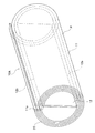
ペーパーダンパ10Aは、図2に示すように、厚紙P(板紙)を円筒状に巻いた筒状体20であり、渦巻き状の周壁部11と、周壁部11の内周側の縁部11aから周壁部11の径方向に延びた径方向壁部12と、を備えている。
ペーパーダンパ10Aの軸方向の長さは、図1に示すように、第一推進軸3の中空部の軸方向の長さよりも小さく形成されている。
As shown in FIG. 2, the paper damper 10 </ b> A is a
The axial length of the
なお、ペーパーダンパ10Aに用いられる厚紙Pの厚さは、第一推進軸3の鋼管部の厚さよりも薄いものである。本実施形態の各図では、ペーパーダンパ10Aの構成を分かり易く説明するために、厚紙Pの厚さを適宜に誇張して図示している。
Note that the thickness of the cardboard P used for the
周壁部11は、図2に示すように、厚紙Pをペーパーダンパ10Aの軸回りに三回に亘って厚紙Pを渦巻き状に巻いた部位である。
周壁部11の外径は、図3(b)に示すように、ペーパーダンパ10Aを第一推進軸3内に挿入した状態において、周壁部11の外周面が第一推進軸3の内周面に密着するように設定されている。
As shown in FIG. 2, the
The outer diameter of the
径方向壁部12は、図3(a)に示すように、周壁部11の内周側の縁部11aにおいて、厚紙Pを周壁部11の径方向に折り曲げた部位である。径方向壁部12は、図2に示すように、周壁部11の中心位置を通過して、周壁部11の径方向に配置されている。また、径方向壁部12は、周壁部11の軸方向の両端部に亘って形成されている。このように、径方向壁部12に周壁部11を巻いた状態となっている。
As shown in FIG. 3A, the
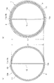
図3(a)に示すように、径方向壁部12の先端部12aから基端部12bまでの長さL2(周壁部11の径方向の長さ)は、第一推進軸3の内径L1(図3(b)参照)よりも僅かに大きく形成されている。
したがって、図3(b)に示すように、ペーパーダンパ10Aを第一推進軸3内に挿入した状態では、径方向壁部12の両端部12a,12bが周壁部11の内周面に押し付けられ、径方向壁部12は周壁部11内で撓んだ状態または圧縮された状態となる。これにより、径方向壁部12から周壁部11の内周面に付勢力が作用する。
As shown in FIG. 3A, the length L2 from the
Therefore, as shown in FIG. 3B, in a state where the paper damper 10 </ b> A is inserted into the
次に、前記したペーパーダンパ10Aを形成するとともに、ペーパーダンパ10Aを第一推進軸3内に挿入するための組付工具30について説明する。
Next, the
組付工具30は、図4(a)に示すように、円柱状の本体部31を有している。
本体部31の外周面は、周壁部11が巻き付けられる部位である。本体部31の外径は、第一推進軸3の内径よりも小さく形成されており、本体部31の外周面に周壁部11を巻き付けた状態で、組付工具30を第一推進軸3内に挿入することができるように設定されている(図5(b)参照)。
また、本体部31の基端面31bには、作業者が把持するための把持部31cが設けられている。
As shown in FIG. 4A, the
The outer peripheral surface of the
The
本体部31の外周面には、軸方向に延びたスリット32が開口している。スリット32は、径方向壁部12(図4(b)参照)が挿入される部位である。
スリット32の軸方向の両端部は、本体部31の先端面31aおよび基端面31bに開口している。また、スリット32の開口幅(本体部31の周方向の幅)は、図4(b)に示すように、厚紙Pを挿入可能な大きさに形成されている。
A slit 32 extending in the axial direction is opened on the outer peripheral surface of the
Both end portions of the
また、スリット32は、深さ方向に直交する方向に湾曲している。そして、スリット32の底面32aから開口部32bまでの長さL5は、第一推進軸3(図3(b)参照)の内径L1よりも大きく形成されている。
The
次に、前記した組付工具30を用いてペーパーダンパ10Aを第一推進軸3内に固定するための組付方法について説明する。
Next, an assembly method for fixing the paper damper 10 </ b> A in the
まず、図4(b)に示すように、組付工具30のスリット32に厚紙Pの一方の縁部を挿入し、厚紙Pの一方の縁部をスリット32の底面32aに当接させる。この状態で、スリット32の開口部32bにおいて、厚紙Pの他方の縁部側の部位を本体部31の外周面に沿って折り曲げる。これにより、スリット32内に挿入された厚紙Pによって径方向壁部12が形成される。
First, as shown in FIG. 4B, one edge of the thick paper P is inserted into the
スリット32の底面32aから開口部32bまでの長さL5は、第一推進軸3(図3(b)参照)の内径L1よりも大きく形成されている。したがって、スリット32内に形成された径方向壁部12は、先端部12aから基端部12bまでの長さL2(3(a)参照)が第一推進軸3の内径L1よりも大きくなる。
A length L5 from the
続いて、厚紙Pを本体部31の外周面に巻き付けて、渦巻き状の周壁部11(図3(a)参照)を形成する。これにより、図5(a)に示すように、組付工具30の本体部31にペーパーダンパ10Aが巻き付けられた状態となる。
Subsequently, the cardboard P is wound around the outer peripheral surface of the
そして、本体部31にペーパーダンパ10Aを巻き付けた状態で、図5(b)に示すように、本体部31の先端面31a側から、組付工具30を第一推進軸3内に挿入し、組付工具30およびペーパーダンパ10Aを第一推進軸3内に配置する。これにより、周壁部11の外周面が第一推進軸3の内周面に接した状態となる。
Then, with the
続いて、図5(c)に示すように、第一推進軸3内の組付工具30を本体部31の基端面31b側から引き抜く。このとき、ペーパーダンパ10Aは、周壁部11の外周面と第一推進軸3の内周面との摩擦抵抗によって、第一推進軸3内に保持され、組付工具30のみが第一推進軸3から引き抜かれる。
Subsequently, as shown in FIG. 5C, the
第一推進軸3内に取り残されたペーパーダンパ10Aは、図3(b)に示すように、径方向壁部12の両端部12a,12bが周壁部11の内周面に押し付けられる。これにより、周壁部11の外周面が第一推進軸3の内周面に押し付けられ、第一推進軸3内にペーパーダンパ10Aが固定される。
In the paper damper 10 </ b> A left in the
以上のようなペーパーダンパ10Aでは、図3(b)に示すように、ペーパーダンパ10Aを第一推進軸3内に挿入すると、径方向壁部12は第一推進管3の略中心位置を通過するように配置される。そして、径方向壁部12は第一推進管3の内径よりも大きいため、径方向壁部12の両端部12a,12bが周壁部11の内周面に押し付けられる。そして、径方向壁部12から周壁部11の内周面に付勢力が作用し、周壁部11の外周面が第一推進軸3の内周面に押し付けられる。
このように、ペーパーダンパ10Aを第一推進軸3内に挿入する作業のみによって、ペーパーダンパ10Aを第一推進軸3内に簡単かつ確実に固定することができるため、作業効率を高めることができる。
In the
As described above, the
また、径方向壁部12が周壁部11の内周面に押し付けられることで、周壁部11の外周面が第一推進軸3の内周面に密着した状態を保つことができる。したがって、周壁部11が経年変化によって縮径して、周壁部11の外周面が第一推進軸3の内周面から離れるのを防ぐことができ、防振性能の低下を防ぐことができる。また、ペーパーダンパ10Aが第一推進軸3内で軸方向に移動するのを防ぐことができ、第一推進軸3の重量バランスを保つことができる。
Further, the
また、図4(a)に示す組付工具30を用いたペーパーダンパ10Aの組付方法では、組付工具30を用いてペーパーダンパ10Aを簡単に形成することができる(図3(b)参照)。さらに、図5(b)に示すように、組付工具30とともにペーパーダンパ10Aを第一推進軸3内に挿入し、図5(c)に示すように、組付工具30のみを第一推進軸3から引き抜くことで、ペーパーダンパ10Aを第一推進軸3内に簡単かつ確実に固定することができる。
Further, in the method of assembling the
また、組付工具30では、図4(b)に示すように、厚紙Pの一方の縁部をスリット32に挿入し、厚紙Pを折り曲げると、径方向壁部12の先端部12aから基端部12bまでの長さL2(図3(a)参照)が第一推進軸3の内径L1よりも大きくなる。このように、径方向壁部12を簡単に形成することができる。
Further, in the assembling
以上、本発明の第一実施形態について説明したが、本発明は前記第一実施形態に限定されることなく、その趣旨を逸脱しない範囲で適宜に変更が可能である。
第一実施形態のペーパーダンパ10Aの周壁部11は、図3(a)に示すように、軸周りに三回に亘って厚紙Pを巻回させているが、厚紙Pを巻き付ける回数は限定されるものではない。
As mentioned above, although 1st embodiment of this invention was described, this invention is not limited to said 1st embodiment, In the range which does not deviate from the meaning, it can change suitably.
As shown in FIG. 3A, the
第一実施形態では、図1に示すように、径方向壁部12が推進軸1の軸方向に連続して形成されているが、複数の径方向壁部12を推進軸1の軸方向に間隔を空けて形成してもよい。
In the first embodiment, as shown in FIG. 1, the
第一実施形態では、図1に示すように、自動車の推進軸1に用いられるペーパーダンパ10Aを例として説明しているが、本発明のペーパーダンパは、各種の中空管に適用可能である。
In the first embodiment, as illustrated in FIG. 1, the
(第二実施形態)
次に、本発明の第二実施形態のペーパーダンパ10Bについて説明する。
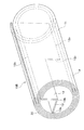
第二実施形態のペーパーダンパ10Bは、図6に示すように、第一実施形態のペーパーダンパ10A(図2参照)と略同様な構成であり、径方向壁部12に折り曲げ部13が形成されている点が異なっている。
(Second embodiment)
Next, the
As shown in FIG. 6, the paper damper 10 </ b> B of the second embodiment has substantially the same configuration as the paper damper 10 </ b> A (see FIG. 2) of the first embodiment, and a
第二実施形態のペーパーダンパ10Bの筒状体20では、図6に示すように、径方向壁部12の軸方向の中間部において、先端部から高さ方向の半分に亘ってスリット12cが形成されている。そして、スリット12cを境界にして、径方向壁部12の軸方向の一方側(図6の手前側)を直角に折り曲げることで、折り曲げ部13が形成されている。
In the
図7(a)に示すように、折り曲げ部13の先端部13aから基端部13bまでの長さL4は、第一推進軸3(図7(b)参照)の内周の半径L3よりも大きく形成されている。
したがって、図7(b)に示すように、ペーパーダンパ10Bを第一推進軸3内に挿入すると、折り曲げ部13の先端部13aが周壁部11の内周面に押し付けられ、折り曲げ部13は周壁部11内で撓んだ状態または圧縮された状態となる。そして、折り曲げ部13から周壁部11の内周面に付勢力が作用する。
As shown in FIG. 7A, the length L4 from the
Therefore, as shown in FIG. 7B, when the
この構成では、径方向壁部12の両端部12a,12bおよび折り曲げ部13の先端部13aによって、周壁部11は三方向から第一推進軸3の内周面に押し付けられるため、ペーパーダンパ10Bを第一推進軸3内により確実に固定することができる。
In this configuration, the
以上、本発明の第二実施形態について説明したが、第二実施形態も前記第一実施形態と同様に、その趣旨を逸脱しない範囲で適宜に変更が可能である。
第二実施形態では、図7(b)に示すように、径方向壁部12に対して折り曲げ部13が直交しているが、径方向壁部12に対する折り曲げ部13の角度は限定されるものではない。また、複数の折り曲げ部を形成してもよい。
As mentioned above, although 2nd embodiment of this invention was described, 2nd embodiment can be suitably changed in the range which does not deviate from the meaning similarly to said 1st embodiment.
In the second embodiment, as shown in FIG. 7B, the
1 推進軸
3 第一推進軸
4 第二推進軸
4a 連結軸部
5 第一ジョイント
6 等速ジョイント
6a 外輪部材
6b 動力伝達部材
7 第二ジョイント
8 軸受構造体
8a 軸受
8b 防振部材
10A ペーパーダンパ(第一実施形態)
10B ペーパーダンパ(第二実施形態)
11 周壁部
12 径方向壁部
12c スリット
13 折り曲げ部
20 筒状体
30 組付工具
31 本体部
32 スリット
P 厚紙
1
10B Paper damper (second embodiment)
DESCRIPTION OF
Claims (5)
厚紙を筒状に巻いた筒状体からなり、
前記筒状体は、
渦巻き状の周壁部と、
前記周壁部の内周側の縁部から前記周壁部の径方向に延びた径方向壁部と、を備え、
前記径方向壁部の先端部から基端部までの長さは、前記中空管内に挿入した状態の前記周壁部の内径よりも大きいことを特徴とするペーパーダンパ。 A paper damper inserted into the hollow tube,
It consists of a cylindrical body with cardboard rolled into a cylindrical shape,
The cylindrical body is
A spiral peripheral wall,
A radial wall portion extending in a radial direction of the peripheral wall portion from an inner peripheral edge of the peripheral wall portion, and
The paper damper according to claim 1, wherein a length from a distal end portion to a proximal end portion of the radial wall portion is larger than an inner diameter of the peripheral wall portion inserted in the hollow tube.
前記径方向壁部の一部を折り曲げた折り曲げ部が形成されており、
前記折り曲げ部の先端部から基端部までの長さは、前記中空管内に挿入した状態の前記周壁部の内周の半径よりも大きいことを特徴とする請求項1に記載のペーパーダンパ。 In the cylindrical body,
A bent portion is formed by bending a part of the radial wall portion,
The paper damper according to claim 1, wherein a length from a distal end portion to a proximal end portion of the bent portion is larger than a radius of an inner periphery of the peripheral wall portion in a state of being inserted into the hollow tube.
円柱状の本体部を有し、
前記本体部の外周面には、軸方向に延びたスリットが開口するとともに、
前記スリットは、前記本体部の先端面に開口しており、
前記スリットには、前記厚紙の縁部が挿入され、
前記本体部の外周面には、前記厚紙が巻き付けられることを特徴とする組付工具。 An assembly tool for assembling the paper damper according to claim 1 or 2 into the hollow tube,
Having a cylindrical body part,
A slit extending in the axial direction opens on the outer peripheral surface of the main body,
The slit is open to the front end surface of the main body,
In the slit, an edge of the cardboard is inserted,
The assembling tool, wherein the cardboard is wound around an outer peripheral surface of the main body.
前記スリットの底面から開口部までの長さは、前記中空管内に挿入した状態の前記周壁部の内径よりも大きいことを特徴とする請求項3に記載の組付工具。 The slit is curved;
The assembly tool according to claim 3, wherein a length from the bottom surface of the slit to the opening is larger than an inner diameter of the peripheral wall portion in a state of being inserted into the hollow tube.
前記スリットに前記厚紙の縁部を挿入し、前記スリットの開口部において、前記厚紙を前記本体部の外周面に沿って折り曲げることで、前記径方向壁部を形成する段階と、
前記厚紙を前記本体部の外周面に巻き付けて前記周壁部を形成する段階と、
前記本体部に前記ペーパーダンパを巻き付けた状態で、前記組付工具を先端面側から前記中空管内に挿入する段階と、
前記中空管内の前記組付工具を基端面側から引き抜く段階と、を備えていることを特徴とするペーパーダンパの組付方法。 A method for assembling a paper damper using the assembling tool according to claim 3 or 4,
Inserting the edge of the cardboard into the slit, and bending the cardboard along the outer peripheral surface of the main body at the opening of the slit to form the radial wall portion; and
Winding the cardboard around the outer peripheral surface of the main body to form the peripheral wall;
In the state where the paper damper is wound around the main body portion, the step of inserting the assembly tool into the hollow tube from the front end surface side;
A step of pulling out the assembly tool in the hollow tube from the base end surface side, and a method for assembling the paper damper.
Priority Applications (1)
| Application Number | Priority Date | Filing Date | Title |
|---|---|---|---|
| JP2014097434A JP6215768B2 (en) | 2014-05-09 | 2014-05-09 | Paper damper, assembly tool, and assembly method of paper damper |
Applications Claiming Priority (1)
| Application Number | Priority Date | Filing Date | Title |
|---|---|---|---|
| JP2014097434A JP6215768B2 (en) | 2014-05-09 | 2014-05-09 | Paper damper, assembly tool, and assembly method of paper damper |
Publications (2)
| Publication Number | Publication Date |
|---|---|
| JP2015215016A JP2015215016A (en) | 2015-12-03 |
| JP6215768B2 true JP6215768B2 (en) | 2017-10-18 |
Family
ID=54752087
Family Applications (1)
| Application Number | Title | Priority Date | Filing Date |
|---|---|---|---|
| JP2014097434A Active JP6215768B2 (en) | 2014-05-09 | 2014-05-09 | Paper damper, assembly tool, and assembly method of paper damper |
Country Status (1)
| Country | Link |
|---|---|
| JP (1) | JP6215768B2 (en) |
Families Citing this family (1)
| Publication number | Priority date | Publication date | Assignee | Title |
|---|---|---|---|---|
| JP2022049824A (en) * | 2020-09-17 | 2022-03-30 | 日立Astemo株式会社 | Constant velocity joints and propeller shafts |
Family Cites Families (4)
| Publication number | Priority date | Publication date | Assignee | Title |
|---|---|---|---|---|
| US4909361A (en) * | 1988-10-13 | 1990-03-20 | Arrow Paper Products Company | Drive shaft damper |
| JP2004195893A (en) * | 2002-12-20 | 2004-07-15 | Toyota Industries Corp | Cylindrical member and its manufacturing method |
| US6966839B2 (en) * | 2003-07-31 | 2005-11-22 | American Axle & Manufacturing, Inc. | Propshaft assembly with damper |
| JP4898599B2 (en) * | 2007-08-29 | 2012-03-14 | 株式会社ショーワ | Propeller shaft |
-
2014
- 2014-05-09 JP JP2014097434A patent/JP6215768B2/en active Active
Also Published As
| Publication number | Publication date |
|---|---|
| JP2015215016A (en) | 2015-12-03 |
Similar Documents
| Publication | Publication Date | Title |
|---|---|---|
| JP6137512B2 (en) | Method for forming a drive shaft tube | |
| JP6711066B2 (en) | Robot, gear device, and method for manufacturing flexible gear | |
| JPWO2014136626A1 (en) | Propeller shaft and propeller shaft adapter member | |
| JP6237883B2 (en) | Power transmission device and manufacturing method thereof | |
| JP6215768B2 (en) | Paper damper, assembly tool, and assembly method of paper damper | |
| JP2018128041A (en) | Assembly of shaft and yoke | |
| JPWO2018021443A1 (en) | Telescopic shaft | |
| JP4981554B2 (en) | Balloon mounting jig and balloon mounting method | |
| JP2014231848A (en) | Dynamic damper | |
| JP4925959B2 (en) | Balloon mounting jig manufacturing method | |
| BR102014023604B1 (en) | shaft shank, shaft shank assembly, method of forming a shaft shank | |
| JP2011501067A (en) | boots | |
| JP6195469B2 (en) | Sheet winding device and method for assembling sheet winding unit | |
| JP6217209B2 (en) | Universal joint yoke | |
| JP2009030679A (en) | Propeller shaft | |
| JP2005053472A (en) | Propeller shaft assembly with vibration damping device | |
| JP2017145945A (en) | Telescopic shaft | |
| JP6591103B1 (en) | Manufacturing method of power transmission shaft | |
| JP5742982B2 (en) | Joint part between shaft and universal joint yoke and method for manufacturing the same | |
| JP6746988B2 (en) | Manufacturing method of telescopic shaft | |
| JP6521065B2 (en) | Universal Joint Yoke | |
| JP6690289B2 (en) | Telescopic shaft | |
| JP6354351B2 (en) | Bearing cup for cross shaft universal joint, manufacturing method thereof, and cross shaft universal joint | |
| JP6398444B2 (en) | Cross shaft type universal joint yoke | |
| JP5488546B2 (en) | Joint part between shaft and universal joint yoke and method for manufacturing the same |
Legal Events
| Date | Code | Title | Description |
|---|---|---|---|
| A621 | Written request for application examination |
Free format text: JAPANESE INTERMEDIATE CODE: A621 Effective date: 20161128 |
|
| TRDD | Decision of grant or rejection written | ||
| A977 | Report on retrieval |
Free format text: JAPANESE INTERMEDIATE CODE: A971007 Effective date: 20170824 |
|
| A01 | Written decision to grant a patent or to grant a registration (utility model) |
Free format text: JAPANESE INTERMEDIATE CODE: A01 Effective date: 20170829 |
|
| A61 | First payment of annual fees (during grant procedure) |
Free format text: JAPANESE INTERMEDIATE CODE: A61 Effective date: 20170921 |
|
| R150 | Certificate of patent or registration of utility model |
Ref document number: 6215768 Country of ref document: JP Free format text: JAPANESE INTERMEDIATE CODE: R150 |
|
| R250 | Receipt of annual fees |
Free format text: JAPANESE INTERMEDIATE CODE: R250 |
|
| S111 | Request for change of ownership or part of ownership |
Free format text: JAPANESE INTERMEDIATE CODE: R313111 |
|
| R350 | Written notification of registration of transfer |
Free format text: JAPANESE INTERMEDIATE CODE: R350 |
|
| R250 | Receipt of annual fees |
Free format text: JAPANESE INTERMEDIATE CODE: R250 |
|
| R250 | Receipt of annual fees |
Free format text: JAPANESE INTERMEDIATE CODE: R250 |
|
| R250 | Receipt of annual fees |
Free format text: JAPANESE INTERMEDIATE CODE: R250 |
|
| R250 | Receipt of annual fees |
Free format text: JAPANESE INTERMEDIATE CODE: R250 |
|
| R250 | Receipt of annual fees |
Free format text: JAPANESE INTERMEDIATE CODE: R250 |